6. Gear Measurement And Testing
|
|
|
- Meryl Amelia Freeman
- 5 years ago
- Views:
Transcription
1 6. Gear Measurement And Testing
2 Introduction Gears are mainly used for transmission of power and motion. They are used in various automobiles, machines, equipments, electronic systems, etc. We already know that gears are used for decreasing or increasing speed. They are also used for changing direction of motion.
3 Types of Gears Spur Gear : It is a cylindrical gear whose tooth traces are straight lines. Helical Gear : It is a cylindrical gear whose tooth traces are straight helices. Spiral Gear : A gear whose tooth traces are curved lines. Straight Bevel : A gear whose tooth traces are straight line generators of a cone. It is Gear conical in form operating on intersecting axes usually at angles. Worm Gear Pair: The worm and mating worm wheel have their axes non-parallel and nonintersecting.

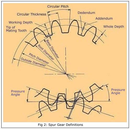
4 Terminology of Spur Gear
5 Base Circle - It is the circle from which involute form is generated. Only the base circle on a gear is fixed and unalterable. Pitch Circle - It is an imaginary circle most useful in calculations. It may be noted that an infinite number of pitch circles can be chosen, each associated with its own pressure angle. Pitch Circle Diameter (P.C.D.) - It is the diameter of a circle which by pure rolling action would produce the same motion as the toothed gear wheel. This is the most important diameter in gears.
6 Module - It is defined as the length of the pitch circle diameter per tooth. Thus if P.C.D. of gear be D and number of teeth N, then module (m) = D/N. It is generally expressed in mm. Diametral Pitch - It is expressed as the number of teeth per inch of the P.C.D. Diametral Pitch = 1/m = N/D pitch Circular Pitch (CP.) - It is the arc distance measured around the pitch circle from the flank of one tooth to a similar flank in the next tooth..-. CP. = πd/n = πm Addendum - This is the radial distance from the pitch circle to the tip of the tooth. Its value is equal to one module. Clearance - This is the radial distance from the tip of a tooth to the bottom of a mating tooth space when the teeth are symmetrically engaged. Its standard value is m.
7 Dedendum - This is the radial distance from the pitch circle to the bottom of the tooth space. Dedendum = Addendum + Clearance = m m = 1.157m. Tooth Thickness - This is the arc distance measured along the pitch circle from its intercept with one flank to its intercept with the other flank of the same tooth. Normally tooth thickness = C.P./2 = πm/2 But thickness is usually reduced by certain amount to allow for some amount of backlash and also owing to addendum correction.
8 Face of Tooth. It is that part of the tooth surface which is above the pitch surface. Flank of Tooth. It is that part of the tooth surface which is lying below the pitch surface. Pressure Angle It is the angle between path of contact and normal drawn to the line joining centers of base circle. Helix Angle : It is the acute angle between the tangent to the helix and axis of the cylinder on which teeth are cut. Lead Angle : It is the acute angle between the tangent to the helix and plane perpendicular to the axis of cylinder Back Lash : The distance through which a gear can be rotated to bring its non-working flank in contact with the teeth of mating gear.
9
10 Analytical Inspection of Gears Gear manufacturing process involves various steps which may need in process inspection. A gear blank, at starting of an operation should be checked for dimensional accuracy of face width, bore, length, diameter, etc. The analytical method of gear involves checking of various parameters of an individual gear. It involves checking concentricity of gear teeth, alignment of each tooth, hardness of gear blank, etc.
11 It also involves the factor that involves accuracy of measurement of these parameter. Analytical method is tedious and it is not preferred by industries because the values of errors in pitch, profile cannot give the error of overall operation of the gear. The analytical method is of useful for students for study and to understand the concept. It will be useful for research and development work in industries and laboratories.
12 Functional Method It involves, mainly checking of gear running with another gear during operation or at actual work. For testing function of gear, master gear is used in combination of manufactured gear. Functional method is used for determining composite errors in vibration, noise during working of gear. If the gear does not satisfy the rolling test, individual or analytical test is carried out. To carry out functional test of the gear, Parkinson gear tester or automating gear rolling machines are used.
13 Rolling Test Rolling test of gears give the composite error analysis of gears. In rolling test, gear to be tested is rolled with the master gear. This test reveals any errors in tooth form, pitch and concentricity of the pitch line. This is the fact, economical and accurate method of gear testing. Results of rolling test of gears are carefully observed and conclusions are drawn regarding the angular rotation per teeth, eccentricity as the error, individual tooth error, etc.
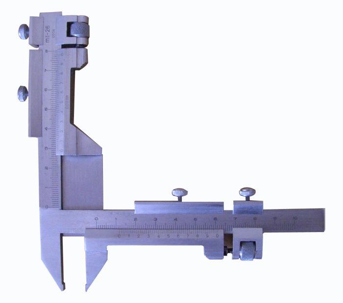
14 Measurement of tooth thickness by gear tooth vernier calliper
15
16 It is used to measure the thickness of gear teeth at the pitch line or chordal thickness of teeth and the distance from the top of a tooth to the chord. The thickness of a tooth at pitch line and the addendum is measured by an adjustable tongue, each of which is adjusted independently by adjusting screw on graduated bars. The effect of zero errors should be taken into consideration. This method is simple and inexpensive.
17 However it needs different setting for a variation in number of teeth for a given pitch and accuracy is limited by the least count of instrument. Since the wear during use is concentrated on the two jaws, the calliper has to be calibrated at regular intervals to maintain the accuracy of measurement.
18
19 The tooth thickness is generally measured at pitch circle and is, therefore, referred to as pitch-line thickness of tooth. The gear tooth vernier has two vernier scales and they are set for the width (w) of the tooth and the depth (d) from the top, at which w occurs. Considering one gear tooth, the theoretical values of w and d can be found out which may be verified by the instrument.
20 In Fig , it may be noted that w is a chord ADB, but tooth thickness is specified as an arc distance AEB. Also the distance d adjusted on instrument is slightly greater than the addendum CE, w is therefore called chordal thickness and d is called the chordal addendum.
21 In the above sketch d is chordal addendum which can be calculated as d = [(N m)/2] [1+(2/N)-cos(90/N)] N Number of teeth M module Tooth thickness can be calculated using gear tooth vernier. By setting d in vertical vernier, horizontal vernier gives w and can be verified by w = N m sin(90/n)
22 Measurement of tooth thickness by Constant Chord Method. In the above method, it is seen that both the chordal thickness and chordal addendum are dependent upon the number of teeth. Hence for measuring a large number of gears for set, each having different number of teeth would involve separate calculations, thus the procedure becomes tedious and timeconsuming one.
23 The constant chord method does away with these difficulties. Constant chord of a gear is measured where the tooth flanks touch the flanks of the basic rack. The teeth of the rack are straight and inclined to their centre lines at the pressure angle as shown in Fig
24
25 Also the pitch line of the rack is tangential to the pitch circle of the gear and,- by definition, the tooth thickness of the rack along this line is equal to the arc tooth thickness of the gear round its pitch circle. Now, since the gear tooth and rack space are in contact in the symmetrical position at the points of contact of the flanks, the chord is constant at this position irrespective of the gear of the system in mesh with the rack.
26 The measurement of tooth thickness at constant chord simplified the problem for all number of teeth. If an involutes tooth is considered symmetrically in close mesh with a basic rack form, then it will be observed that regardless of the number of teeth for a given size of tooth (same module), the contact always occurs at two fixed point A and B. AB is known as constant chord.
27 The constant chord is defined as the chord joining those points, on opposite faces of the tooth, which make contact with the mating teeth when the centre line of the tooth lies on the line of the gear centers. The value of AB and its depth from the tip, where it occurs can be calculated mathematically and then verified by an instrument. The advantage of the constant chord method is that for all number of teeth (of same module) value of constant chord is same. In other words, the value of constant chord is constant for all gears of a meshing system.

28 The Base Tangent Method Or David Brown tangent comparator Or Flange Micrometer
29 The purpose of tangent tester is to determine the mean value and variation in base tangent length. It is measured between two parallel measuring surfaces tangential to unlike gear teeth falnk. In this method, the span of a convenient number of teeth is measured with the help of the tangent comparator. This uses a single vernier caliper and has, therefore, the following advantages over gear tooth vernier which used two vernier scales : (i) the measurements do not depend on two vernier readings, each being function of the other.
30 (ii) the measurement is not made with an edge of the measuring jaw with the face. Consider a straight generator (edge) ABC being rolled back and forth along a base circle. The tangent length can be calculated as d = N m cos ø [tan ø ø (pia/2n) + (pia S/N) Where, N Number of teeth M module Ø Pressure angle S No. of teeth between two anvils.
31 Direct values of d are available for different S, N and m. N (Teeth on Gear) S (Teeth to be spanned) 10 to to to to to to The instrument essentially consists of a fixed anvil and a movable anvil. There is a micrometer on the moving anvil side and this has a very limited movement on either side of the setting.
32 The distance is adjusted by setting the fixed anvil at desired place with the help of looking ring and setting tubes. The movable anvil can be also locked by using slip gauges for setting proper calculate distance. Difference of reading which is set and measured can be calculated using micrometer.
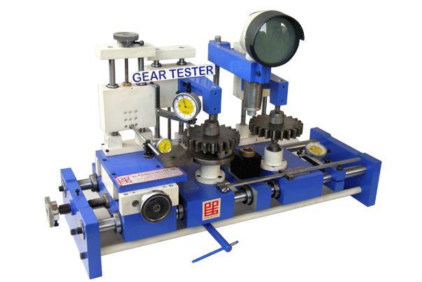
33 Parkinson s Gear Tester
34
35 The principle of this device is to mount a standard gear on a fixed vertical spindle and the gear to be tested on another similar spindle mounted on a sliding carriage, maintaining the gears in mesh by spring pressure. Movements of the sliding carriage as the gears are rotated are indicated by a dial indicator, and these variations are a measure of any irregularities in the gear under test; alternatively a recorder can be fitted, in the form of a waxed circular chart and records made of the gear variation in accuracy of mesh.
36 Construction One fixed spindle and other movable spindle is mounted on flat base. The movable spindle moves along with base by rolling action on the main base plate as shown in figure. A master gear is mounted on the fixed spindle whereas a gear to be tested is mounted on a movable spindle. The dial gauge is set to note the errors whose pointer touches the floating body.
37 Working When master gear is rotated slowly, a gear to be tested will also get rotation movement because of their meshing. Errors in the manufactured gear cause the gear to move away from the centerline of spindle. When the on test moves, the floating body also moves by the same distance. Because of displacement of floating body, dial gauge gives displacement. The variations in the readings can be observed and platted in the graphical format.
38 Limitations Maximum 300 mm diameter gears can be tested. The floating body is very sensitive and hence readings are to be taken very carefully. Accuracy up to 1µm can be possible while measurement. Only composite errors in the gears can be checked not individual one. Measurement depends upon the master gear.
39 Involute Measurement Involute is a curve plotted by a point on a straight line which rolls around a circle without slipping. Involute measurement is done by 1) By profile projector 2) By Involute measuring machine

40 Involute Measuring Machine
41 The basic principle of working is that if a straight edge is rolled around a base circle without slipping, the stylus of the dial gauge attached as above, gives a involute. The gear to be tested is mounted on a mandrill. The circular disc of the same size as that of PCD is also to be mounted on the same mandrill. The straight edge on the disc, which is tangent rolls around the disc, generates a involute and the variation is recorded by dial gauge. A electronics plotter can be used instead of dial gauge for recording purpose.

42 Pitch Measuring Machine
43
44 This instrument has three tips. One is the fixed measuring tip, other one is the sensitive tip whose position can be adjusted by a screw and the further movement of it is transmitted through a leverage system to the dial indicator and the third tip is the supplementary adjustable stop which is meant for the stability of the instrument and its position can also be adjusted by a screw. The distance between the fixed and sensitive tip is set to be equivalent to the base pitch of the gear with the help of slip gauges.
45 The properly set-up instrument is applied to the gear so that all the three tips contact the tooth profile. The reading on dial indicator is the error in the base pitch.
46 Procedure of Measurement The distance between tip (1) and (2) is set to a standard using slip gauges when dial gauge is showing a readings considered as zero. The machine is then applied to the gear under test. All three tips are made contact to gear under test. Reading of dial indicator shows the variation in pitch. Repeat the procedure for next pair of gear tooth.
47 Errors in Gear Following are various gear errors that can be checked while analytical inspection is carried out. 1) Profile 2) Spacing 3) Pitch 4) Run out 5) Gear Tooth Thickness 6) Lead 7) Backlash. The Errors are 1) Cumulative pitch error 2) The tooth thickness error 3) Cyclic error 4) Run out 5) Radial Run out 6) Backlash
48 Cumulative pitch error - It is defined as the actual length between corresponding flanks of teeth not adjacent to each other. The tooth thickness error It is the difference in actual tooth thickness and required tooth thickness. Cyclic error - An error occurring during each revolution of the element under consideration. Run out - It is the total range of reading of a fixed indicator with the contact point applied to a surface rotated, without axial movement about a fixed axis.
49 Radial Run out - It is the run-out measured along a perpendicular to the axis of rotation. Backlash It is the play between the matting tooth surfaces i.e. the distance through which a gear can be rotated to bring its nonworking flank in contact to teeth of mating gear. Axial run-out (wobble) - It is the run-out measured parallel to the axis of rotation, at a specified distance from the axis.
50 ? MSBTE QUESTIONS Describe with a neat sketch the use of Vernier gear tooth caliper to measure the chordal thickness of gear tooth on the pitch circle. Describe with neat sketch Parkinson gear tester. Explain principle of measurement of gear tooth thickness using a gear tooth vernier. State and explain any four types of errors in gear. Explain how will you check the involute profile of a spur gear using involute measuring machine.
51 Explain following errors in gears i) Backlash ii) Run out Explain constant chord method for measuring tooth thickness of gear.

52
Parallel-Axis Gear Terminology
 Parallel-Axis Gear Terminology For more detailed coverage of this subject, consult ANSI/AGMA Standard 1012-F90; Gear Nomenclature, Definitions with Terms and Symbols Active Profile- that part of the gear
Improved Processing Research on Arc Tooth Cylindrical Gear
 International Journal of Environmental Monitoring and Analysis 2017; 5(3): 91-95 http://www.sciencepublishinggroup.com/j/ijema doi: 10.11648/j.ijema.20170503.14 ISSN: 2328-7659 (Print); ISSN: 2328-7667
Development of Tooth Contact Pattern on Spiral Bevel Pinion
 Development of Tooth Contact Pattern on Spiral Bevel Pinion Shamanth C 1*, Dr. G Balakumar 2 Assistant Professor, Department of Mechanical Engineering, Global Academy of Technology, Bangalore, Karnataka,
Disclosure to Promote the Right To Information
 इ टरन ट म नक Disclosure to Promote the Right To Information Whereas the Parliament of India has set out to provide a practical regime of right to information for citizens to secure access to information
Program Crowned and Straight External Involute Gear Compressive Stress Introduction
 Program 60-5406 Crowned and Straight External Involute Gear Compressive Stress Introduction The ideal uniform load distribution along gear teeth is seldom obtained, because of many factors that include
A Study on Reducing Gear Tooth Profile Error by Finish Roll Forming
 A Study on Reducing Gear Tooth Profile Error by Finish Roll Forming Seizo Uematsu, Donald R. Houser, Sung-Ki Lyu, Long Lu, Ju-Suck Lim Measuring position on line of action (mm) Before rolling After rolling
Program Chordal Height and Tooth Thickness
 Program 60-136--Chordal Height and Tooth Thickness Introduction The purpose of this model is to enable you to calculate the tooth thickness at the reference pitch diameter from the chordal caliper dimensions
Towards an Improved AGMA Accuracy Classification System on Double-Flank Composite Measurements
 Towards an Improved AGMA Accuracy Classification System on Double-Flank Composite Measurements E. Reiter Management Summary AGMA introduced ANSI/AGMA 2015 2 A06 Accuracy Classification System: Radial System
Gear Optimizing with Advanced Calculation Method
 Gear Optimizing with Advanced Calculation Method Gear Optimizing with Advanced Calculation Method Development of the Gear Technology All over the world, more and more gears are manufactured by injection
[3] involuteσⅲ(worm gear design system) English version
![[3] involuteσⅲ(worm gear design system) English version](/thumbs/86/93331284.jpg "[3] involuteσⅲ(worm gear design system) English version") [3] involuteσⅲ(worm gear design system) English version Fig.3.2 Basic rack(worm gear) Fig.3.1 involuteσⅲ(worm gear) 3.1 Abstract This software is a newly developed software that combined both involuteσ
[3] involuteσⅲ(worm gear design system) English version Fig.3.2 Basic rack(worm gear) Fig.3.1 involuteσⅲ(worm gear) 3.1 Abstract This software is a newly developed software that combined both involuteσ
Finite Element Analysis of High Contact Ratio Gear
 10FTM06 AGMA Technical Paper Finite Element Analysis of High Contact Ratio Gear By M. Rameshkumar, G. Venkatesan and P. Sivakumar, DRDO, Ministry of Defence Finite Element Analysis of High Contact Ratio
LION. Application Note PRECISION. Linear Position Measurement with Eddy-Current Sensors. LA March, Applicable Equipment: Applications:
 LION PRECISION Application Note LA02-0061 March, 2013 Linear Position Measurement with Eddy-Current Sensors Position, Displacement Applicable Equipment: Eddy-Current position measurement systems. Applications:
LECTURE 13. Dr. Teresa D. Golden University of North Texas Department of Chemistry
 LECTURE 13 Dr. Teresa D. Golden University of North Texas Department of Chemistry Goniometer circle - centered at the sample, with the x-ray source and detector on the circumference of the circle. Focusing
Program Tooth Thickness/Space Width & Pressure Angle at Shifted Diameter
 Program 60-132 Tooth Thickness/Space Width & Pressure Angle at Shifted Diameter Introduction The purpose of this model is to enable you to find the tooth thickness (or space width for internal gears),
KISSsoft instructions: Crossed helical gear pair, combination of a steel worm with a plastic gear and deep tooth form
 KISSsoft instructions: Crossed helical gear pair, combination of a steel worm with a plastic gear and deep tooth form Release 10/2008 Last correction 22.01.2009 08:49:00 Calculation example Project No
Standard Practice for Verification of Testing Frame and Specimen Alignment Under Tensile and Compressive Axial Force Application 1
 Designation: E1012 14 Standard Practice for Verification of Testing Frame and Specimen Alignment Under Tensile and Compressive Axial Force Application 1 This standard is issued under the fixed designation
Producing Large-Sized, Skew Bevel Gear Pinion Using Multi-Axis Control and Multi-Tasking Machine Tool I. Tsuji, K. Kawasaki and H.
 technical Producing Large-Sized, Skew Bevel Gear Pinion Using Multi-Axis Control and Multi-Tasking Machine Tool I. Tsuji, K. Kawasaki and H. Gunbara This paper proposes a method for the manufacture of
Nuclear Associates
 Nuclear Associates 37-013 GARD Users Manual March 2005 Manual No. 37-013-1 Rev. 2 2004, 2005 Fluke Corporation, All rights reserved. Printed in U.S.A. All product names are trademarks of their respective
Description The 4000 Series offers up to 8600 in-lb of torque and 25 gpm (continuous ratings). This is the corner stone of the Char-Lynn line.
. This is the corner stone of the Char-Lynn line.") Highlights Features ety of mounting flanges and output shafts options Benefits motor into a system tough applications Applications Description The 0 Series offers up to 0 in-lb of torque and gpm (continuous
Highlights Features ety of mounting flanges and output shafts options Benefits motor into a system tough applications Applications Description The 0 Series offers up to 0 in-lb of torque and gpm (continuous
Experimental Study on Gear Extrusion Machining Process of Gearbox Synchronizer Gear Hub
 Experimental Study on Gear Extrusion Machining Process of Gearbox Synchronizer Gear Hub SHI Yaochen 1, a,li Zhanguo 2, b,lin Dan 3, c,li Qinghua 1, d 1 Changchun University, Changchun, 130022, China 2
GEAR TOOTH MODIFICATION FOR NOISE REDUCTION IN AUTOMOTIVE TRANSMISSIONS
 International Journal of Mechanical Engineering and Technology (IJMET) Volume 9, Issue 5, May 2018, pp. 64 74, Article ID: IJMET_09_05_009 Available online at http://www.iaeme.com/ijmet/issues.asp?jtype=ijmet&vtype=9&itype=5
SCOPE OF ACCREDITATION TO ISO/IEC 17025:2005 & ANSI/NCSL Z
 SCOPE OF ACCREDITATION TO ISO/IEC 17025:2005 & ANSI/NCSL Z540-1-1994 MASTER GAGE & TOOL CO. 112 Maplewood Street Danville, VA 24540 Sean Cobb Phone: 434 836 4243 CALIBRATION Valid To: June 30, 2018 Certificate
Symposium on Occlusal Articulation. Mandibular Movement Recordings and Articulator Adjustments Simplified. Harry C. Lundeen, D.D.S.
 Symposium on Occlusal Articulation Mandibular Movement Recordings and Articulator Adjustments Simplified Harry C. Lundeen, D.D.S. Judging from the volume of writing that has appeared in the dental literature
Challenges of High Speed Splicing
 Challenges of High Speed Splicing Richard S. Tetro V.P. Technical Director Black Clawson Converting Machinery Inc. Fulton NY http://bcconverting.com ABSTRACT: Reliability is a key objective of any continuous
Figure 2. Pinion with original cutting tool marks. Polishing on right side is caused by misalignment. Figure 3. Severe gear profile wear.
 Bill Hankes, A-C Equipment Services, USA, explains why it is essential to minimise wear to girth gearing in order to achieve proper operation and maximise service life, and discusses the importance of
ISSUES ON CYLINDRICAL GEARINGS WITH ASYMMETRIC TEETH
 ISSUES ON CYLINDRICAL GEARINGS WITH ASYMMETRIC TEETH Asistent Eng. Sándor RAVAI NAGY, Prof. Eng. Mircea LOBONTIU, Ph.D. North University of Baia Mare, ROMANIA Abstract: This scientific paper approaches
KISSsoft 03/2013 Tutorial 11
 KISSsoft 03/2013 Tutorial 11 Tooth Form Optimizations, Tooth Form Modifications specifically for Plastic, Sintered, Wire-eroded and Form-forged Gears KISSsoft AG Rosengartenstrasse 4 8608 Bubikon Switzerland
Program AGMA Gear Classification and Inspection Handbook Model
 Program 60-100 AGMA Gear Classification and Inspection Handbook Model Introduction This model calculates the dimensional tolerances for unassembled spur, helical, double helical, and herringbone gears
Technique Guide. SureLock Distal Targeting Device. C-arm guided targeting for trochanteric fixation nail.
 Technique Guide SureLock Distal Targeting Device. C-arm guided targeting for trochanteric fixation nail. Table of Contents Introduction SureLock Distal Targeting Device 2 Surgical Technique Preoperative
A novel cementless option. Zimmer NexGen Trabecular Metal Primary Patella Surgical Technique
 A novel cementless option Zimmer NexGen Trabecular Metal Primary Patella Surgical Technique Zimmer Trabecular Metal Primary Patella 1 Zimmer NexGen Trabecular Metal Primary Patella Surgical Technique
Surveying. 3rd year / College of Dentistry/University of Baghdad ( ) Page 1
 Page 1") د. فائزة Lec.3 Prosthodontics Surveying The ideal requirements for successful removable partial denture are: 1. Be easily inserted and removed by the patient. 2. Resist dislodging forces. 3. It should
د. فائزة Lec.3 Prosthodontics Surveying The ideal requirements for successful removable partial denture are: 1. Be easily inserted and removed by the patient. 2. Resist dislodging forces. 3. It should
Description The 4000 Series offers up to 8600 in-lb of torque and 25 gpm (continuous ratings). This is the corner stone of the Char-Lynn line.
. This is the corner stone of the Char-Lynn line.") Highlights Features displacements, a variety of mounting flanges and output shafts Reliable, proven design High efficiency Environmental protection options Benefits Flexiblilty in designing this motor
Highlights Features displacements, a variety of mounting flanges and output shafts Reliable, proven design High efficiency Environmental protection options Benefits Flexiblilty in designing this motor
DEFORMATION TRANSDUCER CALIBRATOR OPERATION
 The Calibration Company DEFORMATION TRANSDUCER CALIBRATOR OPERATION December 2011 doc#: EMS10 rev: 2 1 DEFORMATION TRANSDUCER CALIBRATOR OPERATION 1.1 Introduction The deformation transducer calibrator
90 VIBROENGINEERING. JOURNAL OF VIBROENGINEERING. MARCH VOLUME 15, ISSUE 1. ISSN
 924. An investigation on helical gear pair stresses incorporating misalignment and detail modification Kuo Jao Huang, Ching Ya Su 924. AN INVESTIGATION ON HELICAL GEAR PAIR STRESSES INCORPORATING MISALIGNMENT
ACCURATE NUMERICAL ANALYSIS OF GEAR STRENGTH BASED ON FINITE ELEMENT METHOD
 31 st December 212. Vol. 46 No.2 25-212 JATIT & LLS. All rights reserved. ACCURATE NUMERICAL ANALYSIS OF GEAR STRENGTH BASED ON FINITE ELEMENT METHOD XUEYI LI, CHAOCHAO LI, DAQIAN GENG, SHOUBO JIANG, BINBING
4766 Research Dr. San Antonio, TX insightdentalsystems.com
 OVERVIEW OF THE INSIGHT DENTAL IMPLANT DELIVERY SYSTEM The IDS system comes in a unit dose implant system where its advantage provides sterile instrumentation in one single-use kit. It is organized to
Fatigue Life Analysis of Spur Gears with Precise Tooth Profile Surfaces
 MATHEMATICAL MODELLING OF ENGINEERING PROBLEMS ISSN: 369-0739 (Print), 369-0747 (Online) Vol. 3, No., June 016, pp. 81-86 DOI: 10.1880/mmep.03007 Licensed under CC BY-NC 4.0 A publication of IIETA http://www.iieta.org/journals/mmep
LOAD SHARING ANALYSIS OF BENDING STRENGTH IN ALTERED TOOTH-SUM GEARS OPERATING BETWEEN A STANDARD CENTER DISTANCE AND MODULE ABSTRACT
 LOAD SHARING ANALYSIS OF BENDING STRENGTH IN ALTERED TOOTH-SUM GEARS OPERATING BETWEEN A STANDARD CENTER DISTANCE AND MODULE A.R.Rajesh Research scholar and Sel.Gr. Lecturer in Mechanical engg., Govt.
Goniometer series 400
 User s Manual Huber Diffraktionstechnik GmbH & Co. KG Sommerstrasse 4 D - 83253 Rimsting Phone +49 (0) 8501 6878-0 Fax +49 (0) 8051 6878-10 info@xhuber.com www.xhuber.com series 400 Manual 400_en-A05 2005
Kois Dento-Facial Analyzer System Instructions
 These instructions apply to the following items: M Panadent Corporation 580 S. Rancho Avenue Colton, California 92324, USA Tel: (909) 783-1841 USA & Canada (800) 368-9777 Kois Dento-Facial Analyzer System
Trabecular Metal Primary Patella
 Trabecular Metal Primary Patella NexGen Complete Knee Solution Surgical Technique Table of Contents Introduction... 2 Prepare the Patella... 2 Patella Reamer Technique... 3 Insetting Technique... 5 Universal
CORESTA RECOMMENDED METHOD N 22
 CORESTA RECOMMENDED METHOD N 22 ROUTINE ANALYTICAL CIGARETTE-SMOKING MACHINE SPECIFICATIONS, DEFINITIONS AND STANDARD CONDITIONS (August 1991) 0. INTRODUCTION This CORESTA Recommended Method includes the
ilearnalignment Training topics covered in the introduction and master versions
 ilearnalignment Training topics covered in the introduction and master versions ilearnalignment [Introduction] If you need an introduction to shaft alignment in order to understand the benefits and the
Orthotics Measurement Board for Tibial Torsion and Toe-Out
 Orthotics Measurement Board for Tibial Torsion and Toe-Out HANS R. LEHNEIS, C.P.O. 2 COORDINATED function of the brace-anatomical complex is dependent upon the configuration and fit of the brace with the
An experimental method to measure gear tooth stivness throughout and beyond the path of contact
 793 An experimental method to measure gear tooth stivness throughout and beyond the path of contact R G Munro 1, D Palmer 2 and L Morrish 1 * 1 School of Engineering, University of Hudders eld, West Yorkshire,
Program Crowned and Straight External Involute Gear EHL Film Thickness
 Program 60-5408 Crowned and Straight External Involute Gear EHL Film Thickness Introduction Lubrication film thickness is obviously an important factor in the lubrication of gears, because it determines
Set for tunneling technique, consisting of 1/3 washtray, tunneling instruments # 1 upper jaw, # 2 lower jaw, # 3 upper / lower jaw combination
 All CE marked products according to the Medical Device Directive 93/42/EEC Microsurgery zepf-dental.com 08-01 08 Instruments for the modified Tunneling Technique 46.040.00 Tunneling Instrument, # 1, for
(12) Patent Application Publication (10) Pub. No.: US 2005/ A1
 Patent Application Publication (10) Pub. No.: US 2005/ A1") (19) United States US 2005O130094A1 (12) Patent Application Publication (10) Pub. No.: US 2005/0130094A1 Graham (43) Pub. Date: Jun. 16, 2005 (54) ORTHODONTIC ACCESSORY ARCH BAR (52) U.S. Cl.... 433/20
(19) United States US 2005O130094A1 (12) Patent Application Publication (10) Pub. No.: US 2005/0130094A1 Graham (43) Pub. Date: Jun. 16, 2005 (54) ORTHODONTIC ACCESSORY ARCH BAR (52) U.S. Cl.... 433/20
TOTAL KNEE ARTHROPLASTY SYSTEM
 SURGICAL TECHNIQUE TOTAL KNEE ARTHROPLASTY SYSTEM 90-SRK-700000 B.0 0 Contents 1. Implant Sizing 2. Surgical Technique a. Incision and Exposure b. Distal Femoral Resection c. Tibial Resection d. Femoral
10 Years Experience in Industrial Phased Array Testing of Rolled Bars
 18th World Conference on Nondestructive Testing, 16-20 April 2012, Durban, South Africa 10 Years Experience in Industrial Phased Array Testing of Rolled Bars Josef MAIER 1 and Gerhard Ferstl 1, 1 Böhler
MM01-Facebow And Bite Registration Procedure Checklist
 MM01-Facebow And Bite Registration Procedure Checklist Bite fork Registration OK Redo 1. Estimate the shape of the patient s arch 2. Place the bite tabs on the bite fork 3. Warm the compound in hot water
PRIMARY POROUS PATELLA WITH TRABECULAR METAL. Surgical Technique
 PRIMARY POROUS PATELLA WITH TRABECULAR METAL Surgical Technique 1 SURGICAL TECHNIQUE FOR NEXGEN PRIMARY POROUS PATELLA * WITH TRABECULAR METAL CONTENTS PREPARE THE PATELLA............... 2 Patella Reamer
Lab Procedure Prior to Try-in
 Lab Procedure Prior to Try-in It is the procedure of attaching the maxillary and mandibular casts to the articulator in their recorded jaw relation. It is also called articulation. The maxillary cast is
Outline. Chapter 12 Treatment Planning Combination of Beams. Opposing pairs of beams. Combination of beams. Opposing pairs of beams
 Chapter 12 Treatment Planning Combination of Beams Radiation Dosimetry I Text: H.E Johns and J.R. Cunningham, The physics of radiology, 4 th ed. http://www.utoledo.edu/med/depts/radther Outline Combination
CETR Adhesion Testing on Glass/Al Surface for Corning Inc.
 CETR Adhesion Testing on Glass/Al Surface for Corning Inc. I. Introduction 1.1 Objective The goal of the study was to differentiate stiction from various glass composites and surface treatments using the
SURGICAL TECHNIQUE GUIDE
 DANGER indicates an imminently hazardous situation which, if not avoided, will result in death or serious injury. WARNING indicates a potentially hazardous situation which, if not avoided, could result
Illustrative exercises for the lectures
 Biomechanics Illustrative exercises for the lectures Ingrid Svensson 2015 1 1. To practise the use of free-body diagram, consider the problem of analyzing the stress in man s back muscles when performing
Horizontal jaw relations: The relationship of mandible to maxilla in a
 Horizontal relations Horizontal jaw relations: The relationship of mandible to maxilla in a horizontal plane (in anteroposterior and side to side direction). a- Protruded or forward relation. b-lateral
Development of a Wear Testing Machine for Dental Crown Application
 Kasetsart J. (Nat. Sci.) 47 : 790-801 (2013) Development of a Wear Testing Machine for Dental Application Panya Aroonjarattham*, Chakrit Suvanjumrat and Ekachai Chaichanasiri ABSTRACT A three axes wear
Gear Tooth Root Fillet Optimization Program User manual
 Gear Tooth Root Fillet Optimization Program User manual AKGears gear tooth root fillet optimization program optimizes the gear tooth root fillet to minimize bending stress concentration. This program is
High Grade Universal Testing Machines
 ALTENMARKT 180, 8280 FÜRSTENFELD TEL.: +43 3382-54060-0 FAX: -27 AUSTRIA, EUROPE WWW.MESSPHYSIK.COM BETA Series High Grade Universal Testing Machines FIELD PROVEN SOLUTIONS - Application examples BETA
Face-Bow Instructions
 M Panadent Corporation 580 S. Rancho Avenue Colton, California 92324, USA Tel: (909) 783-1841 USA & Canada (800) 368-9777 The following procedure is followed when Panadent Bite-Tab compound discs are used
Custom-Made Products / Scientific Research Instruments
 / Scientific Research Instruments Multipurpose X-Ray Diffractometer System For Laboratory Use Multipurpose X-ray diffractometer The instrument shown on the left is a multipurpose 4-axis X-ray diffractometer
A new geometric and mechanical verification device for medical LINACs
 JOURNAL OF APPLIED CLINICAL MEDICAL PHYSICS, VOLUME 3, NUMBER 2, SPRING 2002 A new geometric and mechanical verification device for medical LINACs Keith T. Welsh,* Robert A. Wlodarczyk, and L. E. Reinstein
IS INTERNATIONAL STANDARD. Calculation of load capacity of spur and helical gears - Part 3: Calculation of tooth bending strength
 INTERNATIONAL STANDARD IS0 6336-3 First edition 1996-06-15 Calculation of load capacity of spur and helical gears - Part 3: Calculation of tooth bending strength Calcul de la capacitk de charge des engrenages
KISSsoft Tutorial: Tooth Form Optimizations, Tooth Form Modifications specifically for Plastic, Sintered, Wireeroded and Form-forged Gears
 KISSsoft Tutorial 011: Tooth Form Optimizations, Tooth Form Modifications KISSsoft AG - +41 55 254 20 50 Uetzikon 4 - +41 55 254 20 51 8634 Hombrechtikon - info@kisssoft. AG Switzerland - www. KISSsoft.
This document is a preview generated by EVS
 INTERNATIONAL STANDARD ISO 10300-3 Second edition 2014-04-01 Calculation of load capacity of bevel gears Part 3: Calculation of tooth root strength Calcul de la capacité de charge des engrenages coniques
Instruction Manual No A. Goniometer PS-2138, PS-2137
 Instruction Manual No. 012-08904A Goniometer PS-2138, PS-2137 Goniometer Model No. PS-2138 Contents Introduction......................................................... 3 Probe Mounting......................................................
European Veterinary Dental College
 European Veterinary Dental College EVDC Training Support Document Preparation of Radiograph Sets (Cat and Dog) Document version : evdc-tsd-radiograph_positioning_(dog_and_cat)-20120121.docx page 1 of 13
Setting up Your Home Office
 Setting up Your Home Office The home office is becoming more and more prevalent. Even those who do not work from home on a regular basis have computer workstations set up in the home for personal activities.
KINEMATICS OF PROSTHESIS SHOULDER JOINTS
 KINEMATICS OF PROSTHESIS SHOULDER JOINTS By GERALD GWYNNE Associate Engineer in Research, UCLA UPON REVIEWING MR. KARG'S ARTICLE I WAS IMPRESSED BY THE CLARITY OF HIS DESCRIPTION OF THE RING SHOULDER JOINTS.
Unique Dental Supply. Catalog We Bring World Quality Products to Enhance your Business QUALITY PRODUCTS SINCE 1974
 Panadent Articulating System FINAL:UDS-NL-2013 14-09-22 2:04 PM Page 3 UDS Unique Dental Supply We Bring World Quality Products to Enhance your Business R QUALITY PRODUCTS SINCE 1974 Catalog 2014 Panadent
Principles of. By: Dr. Ahmad Rabah
 Principles of By: Dr. Ahmad Rabah 1. Utilize what's present: Whenever possible, select a design that fits the teeth and soft tissues, rather than choosing one that requires tissue alteration. When minimal
KISSsoft Tutorial: Tooth form optimizations, tooth form. modifications specifically for plastic, sintered, wireeroded and form-forged gears
 KISSsoft AG - +41 55 254 20 50 Uetzikon 4 - +41 55 254 20 51 8634 Hombrechtikon - info@kisssoft.ag Switzerland - www.kisssoft.ag KISSsoft Tutorial: Tooth form optimizations, tooth form KISSsoft Tutorial
PENNDOT e-notification
 PENNDOT e-notification Bureau of Design Engineering Computing Management Division BRADD No. 027 August 30, 2010 Release of Version 3.1.5.0 PennDOT's Bridge Automated Design and Drafting Software (BRADD)
Horizontal Jaw Relation
 Horizontal Jaw Relation Horizontal Jaw Relation It is the relationship of the mandible to the maxilla in a horizontal plane. It can also be described as the relationship of the mandible to the maxilla
of Gear Teeth Sheffield, England. W. A. TUPLIN
 Journal of the National Science Council of Svi Lanka, 1 (1972). 49-54 of Gear Teeth W. A. TUPLIN Sheffield, England. Gears are a very widely-used element of machinery and many millions of them continue
CLASS II AMALGAM RESTORATIONS. Amalgam restorations that restore one or both of the proximal surfaces of the tooth
 CLASS II AMALGAM RESTORATIONS Amalgam restorations that restore one or both of the proximal surfaces of the tooth Initial Tooth Preparation Occlusal outline form (occlusal step).the occlusal outline form
OPERATIVE TECHNIQUE SKS Total Knee Replacement
 OPERATIVE TECHNIQUE SKS Total Knee Replacement Femoral preparation A40577 1 2 5 1: Alignment rod A30049 + A30124 2: Centromedullary rod A40224 4: T-handle A40232 6: Femoral measuring device A40411 + A40414
Hao Ding JUNE Signature of Author: -- ~ ~~a~bepartment of Mechanical Engineering May 18, 2010
 Characterization of a Pre-curved Stylet Distal Tip Manipulation Mechanism for use in Volume Targeting by Hao Ding SUBMITTED TO THE DEPARTMENT OF MECHANICAL ENGINEERING IN PARTIAL FULFILLMENT OF THE REQUIREMENTS
KneeAlign System Surgical Technique Guide
 KneeAlign System Surgical Technique Guide Table of Contents Step 1 System Assembly... 1 Step 2 System Assembly... 2 Step 3 System Assembly... 2 Step 4 System Assembly... 2 Step 5 Sensor Pairing... 2 Step
Calculation of load capacity of bevel gears. Part 3: Calculation of tooth root strength
 Provläsningsexemplar / Preview INTERNATIONAL STANDARD ISO 10300-3 Second edition 2014-04-01 Calculation of load capacity of bevel gears Part 3: Calculation of tooth root strength Calcul de la capacité
A Further Study on High-Contact-Ratio Spur Gears in Mesh with Double-Scope Tooth Profile Modification
 A Further Study on High-Contact-Ratio Spur Gears in Mesh with Double-Scope Tooth Profile Modification Jiande Wang and Ian Howard (Proceedings of th ASME International Power Transmission and Gearing Conference
1 Service factor Determine the required service factor from tables 9 and 10 on pages 87 and 88.
 SKF Couplings SKF Flex Couplings SKF Flex Couplings are designed to accommodate misalignment and shock loads and dampen vibration levels. These easy to install, maintenance-free couplings are available
Microtubule Teardrop Patterns
 Supporting Information Microtubule Teardrop Patterns Kosuke Okeyoshi 1, Ryuzo Kawamura 1, Ryo Yoshida 2, and Yoshihito Osada 1 * 1 RIKEN Advanced Science Institute, 2-1 Hirosawa, Wako-shi, Saitama 351-0198,
Prof. Trimurni Abidin, drg.,m.kes.,sp.kg(k) Department of Conservative Dentistry Faculty of Dentistry University of Sumatera Utara 2013
 Department of Conservative Dentistry Faculty of Dentistry University of Sumatera Utara 2013") Biomechanics in Restorative Dentistry Prof. Trimurni Abidin, drg.,m.kes.,sp.kg(k) Department of Conservative Dentistry Faculty of Dentistry University of Sumatera Utara 2013 FORCES EXERTED DURING OCCLUSION
Biomechanics in Restorative Dentistry Prof. Trimurni Abidin, drg.,m.kes.,sp.kg(k) Department of Conservative Dentistry Faculty of Dentistry University of Sumatera Utara 2013 FORCES EXERTED DURING OCCLUSION
What is Kinesiology? Basic Biomechanics. Mechanics
 What is Kinesiology? The study of movement, but this definition is too broad Brings together anatomy, physiology, physics, geometry and relates them to human movement Lippert pg 3 Basic Biomechanics the
INNOVATIVE EXERCISES FINALLY REVEALED!!! The weightroom secrets no professional strength coach EVER wanted revealed CAUTION!
 Now Just $19.9 Now Just $19.9 131 INNOVATIVE EXERCISES FINALLY REVEALED!!! The weightroom secrets no professional strength coach EVER wanted revealed CAUTION! You may get unstoppably strong and completely
Imola Lateral IBF System Surgical Technique
 Imola Lateral IBF System Surgical Technique IMOLA CIRCUIT TABLE OF CONTENTS Design Rationale Instructions for Use Surgical Technique 1. Table Mounting 2. Surgical Planning & Targeting 3. Access and Preparation
AN EVALUATION OF MANDIBULAR BORDER MOVEMENTS THEIR CHARACTER AND SIGNIFICANCE
 AN EVALUATION OF MANDIBULAR BORDER MOVEMENTS THEIR CHARACTER AND SIGNIFICANCE HARRY C. LUNDEEN, D.D.S. EDWIN F. SHRYOCK, D.D.S.,M.S. and CHARLES H. GIBBS, PhD. The University of Florida, College of Dentistry,
Cutting instruments. Instruments
 Instruments أﻧﺲ اﻟﻌﺒﯿﺪي. د The removal and shaping of tooth structure are essential aspects of restorative dentistry. Initially this was a difficult process accomplished entirely by the use of - Hand instruments.
GSG YOUR SOURCE FOR SPECIAL GAGES MORE TECHNICAL INFORMATION AVAILABLE AT GSG WEB SITE
 GASTONBURY ggg NEED IT FAST REDINE SERVICE AVAIABE OVER 4,000 THREAD ITEMS IN STOCK WWW.AGE.COM YOUR SOURCE FOR SPECIA GAGES MORE TECHNICA INFORMATION AVAIABE AT WEB SITE Table of Contents Index Products
Articulator Instructions
 M Panadent Corporation 580 S. Rancho Avenue Colton, California 92324, USA Tel: (909) 783-1841 USA & Canada (800) 368-9777 Raise and lock incisal pin and support pin (arrow) at least 5mm above incisal table.
Resurfacing Patellar Preparation
 Surgical Technique Resurfacing Patellar Preparation Primary Total Knee Arthroplasty LEGION Total Knee System Resurfacing Patellar preparation Contents Introduction...2 Instrument assembly...3 Resurfacing
US Patent No. 6,309,396B1. G. David Ritland, M.D.
 US Patent No. 6,309,396B1 G. David Ritland, M.D. The Femur Finder is designed to direct the guide wire into the medullary canal. Do not use it to manipulate the fracture fragments, reduce the fracture,
Distal Cut First Femoral Preparation
 Surgical Technique Distal Cut First Femoral Preparation Primary Total Knee Arthroplasty LEGION Total Knee System Femoral preparation Contents Introduction...3 DCF femoral highlights...4 Preoperative planning...6
Installation of force transducers
 Installation of force transducers Force transducers have reached a high technical standard in recent years. Transducers achieve part of their high accuracy due to improved possibilities for calibration.
SIMULATOR FOR TESTING THE FRICTION TORQUE OF THE FEMORAL HEAD OF A HIP PROSTHESIS
 Bulletin of the Transilvania University of Braşov Vol. 8 (57) No. 2-2015 Series I: Engineering Sciences SIMULATOR FOR TESTING THE FRICTION TORQUE OF THE FEMORAL HEAD OF A HIP PROSTHESIS S. MIHAI 1 V. FILIP
Scientific Inquiry Review
 Scientific Inquiry Review Adapted from Regentsprep.org Be able to USE AND APPLY the steps of the scientific method to solve a problem and design an experiment: Scientific Method: 1. Make observations about