Surgical Technique 1
|
|
|
- Hilda Hoover
- 6 years ago
- Views:
Transcription

1 1 Surgical Technique

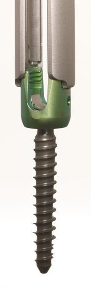
2 TELLURIDE 2 MIS SPINAL FIXATION SYSTEM The Telluride 2 MIS Spinal Fixation System is a simple, robust and versatile minimally invasive pedicle screw system consisting of implants and instruments to provide vertebral stabilization of spinal segments in the thoracic, lumbar and sacral regions. The system features: Cannulated polyaxial pedicle screws Titanium rods Surgeon designed instrumentation Uses either a Percutaneous or Miniopen approach with a series of small, posterior incisions The system provides: Reduced muscle trauma & pain Shorter hospital stays Faster return to normal activities 2

3 TELLURIDE 2 MIS SPINAL FIXATION SYSTEM 3
4 PREOPERATIVE PREPARATION Review and inspect all instrumentation and implants prior to sterilization. Replace or add any needed components for the planned surgery. Surgeon must be fully experienced with the required posterior, non-cervical (T1-S2/Ilium) instrumentation techniques. Read the Telluride 2 Instructions for Use (IFU) for a complete list of prescribing information. SURGICAL EXPOSURE AND SITE PREPARATION Patient is positioned prone on a radiolucent table and draped in the usual manner. With fluoroscopy and preoperative imaging, determine the location of the incision, typically cm from the midline. The Telluride 2 system is designed for minimally invasive techniques where small incisions are utilized. This system may be used to perform MIS Percutaneous or standard mini-open techniques. For Percutaneous Techniques: Utilizing a percutaneous approach, make an appropriate skin incision. Finger dissect between the multifidus and longissimus. Palpate to the facet joint, lamina and base of the spinous process to identify the pedicle. Repeat steps for each pedicle where a screw is to be placed. For Mini-open Techniques: Using a paramedian approach ( Wiltse -like approach), make an appropriate skin and fascia incision to establish a muscle plane path to locate the pedicles perform blunt dissection of the muscle planes down to the facet joints. 4


.")
5 TARGETING NEEDLE AND GUIDE WIRE PLACEMENT Using fluoroscopy, insert the targeting needle to the level of the pedicle through the dissected muscle plane. Confirm the targeting needle is safely placed and has the correct trajectory using a combination of AP and Lateral fluoroscopy, or by orienting fluoroscopy in the plane of the pedicle. Note: This must be done with great care to assure that the needle does not violate the canal or neural foramen. Tap the targeting needle into the vertebral body until depth is satisfactory, typically 1cm past the posterior margin of the vertebral body. As targeting needle is being inserted, verify trajectory and depth using fluoroscopy. Remove the inner stylus and insert the K-wire to the appropriate depth typically (50% of the vertebral body). Note: There are several different techniques /methods for inserting the guide wire. Carefully remove the targeting needle while maintaining control of the depth of the guide wire. Repeat this procedure for the remaining pedicles. 5


6 SOFT TISSUE DILATION Keeping the guide K-wire steady, insert the concentric sized dilators (starter, second and final) over the guide wire. Once the final dilator has been placed, remove the starter dilator tube, leaving the second and final dilator in place. Note: It is critical to maintain control of the guide wire while placing and removing the dilators. PEDICLE PREPARATION Insert the correctly sized cannulated tap over the guide wire, through the second dilator. Note: For hard cortical bone, the cannulated awl can be used over the guide wire to penetrate the pedicle prior to tapping. Tap to the desired length while maintaining position and depth of the guide wire. Note: The tap is threaded to 30mm which can aid in fluoroscopic determination of pedicle screw length. Also, it is important to not tap to the tip of the guide wire to prevent the guide wire from becoming inadvertently disengaged from the bone. Tip: Periodically use fluoroscopy to verify the tap is following the trajectory of the guide wire during insertion. Also, when advancing or removing the tap, pay careful attention to maintaining the guide wire depth with a needle driver and periodic fluoroscopic images. 6


7 CONNECTING OUTER/INNER TUBES TO THE PEDICLE SCREW Holding the screw at the base of the head, connect the outer middle tube tabs by rotating 90 degrees into the slots of the screw head. Insert the inner locking middle tube into the outer tube such that slots of the inner and outer tube are aligned. While paying close attention to the alignment and seating of the four tabs on the inner tube with their matching indentations on the screw head, turn the threaded end clockwise until it is tightly threaded into the outer tube. Use the interlocking tube tightener to firmly secure the tubes together to prevent unthreading intraoperatively. Repeat this for all the necessary screws. 7


8 PEDICLE SCREW ASSEMBLY Insert the cannulated bone screw driver assembly into the center of the assembled tubes, assuring the forks of the driver are properly aligned in the slots of the screw head. Tip: If the screw driver does not fully seat, rotate the screw shank until the driver drops into place. Rotate the outer sleeve of the driver clockwise to tighten the screw/tube assembly. Attach the two piece cannulated bone screw driver to either the ratcheting straight handle or T-handle. 8


9 PEDICLE SCREW INSERTION Position the cannulated screw over the guide K-wire and slide through the final dilator to the pedicle. Note: Use fluoroscopy to assure that the guide wire does not advance during screw insertion. Tip: Periodically use fluoroscopy to verify the screw is following the trajectory of the guide wire during insertion. Once the pedicle screw reaches the vertebral body, carefully remove the guide wire. Advance the pedicle screw to the desired depth using fluoroscopy. In order for the screw head to remain polyaxial, the head of the screw should not be advanced all the way to the bone surface. Remove the cannulated bone screw driver by turning the knob at the top of the outer sleeve counter-clockwise. This will disengage the driver from the pedicle screw and tube assembly. Note: Final dilator can be removed at this point. 9


10 ROD MEASUREMENT Insert the rod measurement calipers into the tops of the tube assemblies at each end of the construct, so that the calipers span the length of the intended levels. Verify that each arm of the calipers is seated far enough that the black band around each arm is flush with the top of the tubes. Lock the caliper arms by tightening the nut at the top of the calipers. Remove the calipers by pulling up on the caliper arm that can slide up and down. Note: Pay careful attention to maintain the caliper arm distance and not disrupt the measurement. Take the locked calipers to the rod caddy of choice (either straight or curved) and place the end of one caliper arm into the dimple labeled zero. Allow the other arm to fall into whichever corresponding length dimple it aligns with. Note: Measurements account for the necessary overhang of the rod, ensuring that both the bullet nose and notched end of the rod extend outside the screw profile. 10
.")
11 FOR LONG CONSTRUCTS In the event that the rod measurement calipers do not reach from end to end, depth sticks may be used to determine the length of the rod. Insert depth sticks through each tube tower for placement into each of the screw tulips. Note: The depth sticks may also be used to verify the rod position (see page 14). The malleable rod template can be laid across the tops of each stick, in the u-shaped channels to determine proper length. For this method to be successful, each of the screw/tube assemblies must be held parallel to one another; perpendicular to the patient. For longer constructs, the malleable rod template can also be used to assist with capturing the appropriate contour needed for bending a straight rod. Note: The template does not account for either the bullet or notched end of the rod; 15 mm must be added to the length shown by the rod template. 11


 inserters are recommended for shorter constructs.")

12 ROD PLACEMENT Prior to placement of the rod, the muscle splitter may be used to create a pathway between the tube assemblies to facilitate rod insertion. Align the adjacent assembled tubes such that the full open slots are facing each other and the closed portions are facing outward. This position will allow for the rod to be inserted and guided into place. The appropriate rod is selected and grasped. Choose from either the offset left, offset right or in-line rod inserters. Each inserter is designed to facilitate a different rod insertion approach, as needed by technique or anatomy. OFFSET ROD INSERTERS The offset (Left and Right) inserters are recommended for shorter constructs. To load the rod, depress the button on the top of the device and slide the hex shaped end of the rod into the matching recess of the inserter. Note: Pay careful attention to the notch in the end of the rod, making sure that it points directly up along the axis of the instrument shaft. Once the rod is in place, depress the button that is on the front of the inserter handle. This will activate the locking arm of the inserter and secure the rod. Verify that the rod can wiggle, but that it cannot come out. 12


13 The initial insertion of the rod should be as vertical as possible to have the most vertical rod approach angle into the screw tulip. The handle should be as parallel to the patient s torso as possible, with the tip of the inserter held closely to the tube. Each inserter is curved at the end, so that the inserter can wrap around the diameter of the tube assembly during insertion. Once the rod is in the starting position, the handle should be rotated up, vertically. While moving into this position, a downward force should be applied, while also maintaining the inserter tip position relative to the tubes. Once the handle is vertical, the rod should be seated within the screw heads. To release the inserter from the rod, depress the top button, and gently walk the inserter tip straight back, off the end of the rod. Note: During release, pay careful attention not to rock the inserter in the caudal-cranial or mediallateral planes, as this may result in damage to the rod or inserter. 13


14 IN-LINE ROD INSERTER When using the in-line rod inserter, prior to depressing the top button, the front trigger must first be held down. Once the top button is down, hold it there, while letting go of the front trigger. The top button will remain down and the rod can now be loaded. Match the hex of the rod with that of the instrument, and make sure the notch in the rod faces up, towards the handle. With the rod held in place, depress the front button of the inserter, which will cause the device to pull the rod into the shaft of the instrument, securing it. Once in place, wiggle the rod to make sure it is secure. With the bullet nose of the rod pointing straight down at the first screw, through the same incision, drive the rod down to the screw tulip. Carefully manipulate the inserter to bring it in line with the screw tulips. 14

15 Once the rod is in place, hold the front button on the inserter, while the top button is depressed to disengage the inserter from the rod. Gently roll the handle of the inserter forward, while the top button is depressed aiding in the smooth release of the rod. TIP: Rod Not Fully Seated While using either inserter type, depth sticks are available to assist in verifying the position of the rod within each screw tulip. Place a depth stick into any screw/tube assembly where the rod position is uncertain. If the white band around the top of the depth stick is flush with the top of the screw/tube assembly, then the rod is within the screw tulip and is at the correct depth. If the depth stick band sits well above the screw/tube assembly, then the rod is within the screw/tube assembly, but is not fully seated. If the depth stick band sits below the top of the screw/tube assembly, then the rod is not within the screw/tube assembly and rod must be reinserted Note: Though the depth sticks have been designed to assist with rod placement verification, rod placement should primarily be confirmed and adjusted accordingly using fluoroscopy. Rod Seated 15


16 ROD REDUCTION If the rod does not fully seat into the screw head, one of three different reduction instruments may be used. Standard Reduction When the needed reduction is 10mm or less, the standard rod pushers, threaded or non-threaded, may be used to gently push down on the rod through the tube assembly. Supplemental Reduction If 10mm-25mm of reduction is needed, the parallel reducers may be used. Each parallel reducer is a two-piece assembly that slides over the tube assembly and locks into place simply by pressing it on. The parallel distracter handle can then be pressed onto the pegged ends of the reducer assembly, and the handles squeezed manually or by translation of the threaded nut. Repeat the reduction method at each screw, until the set screws are at least provisionally tight at each level. Confirm rod placement with fluoroscopy and adjust accordingly. 16


17 If more than 25mm of reduction is required, the threaded reduction caps may be used. Each cap can be placed onto a tube assembly by pulling up on the outer collar of the cap and then pushing the cap down onto the top of the tube assembly. Each cap has three prongs that are designed to seat into one of the six oval windows at the top of the tube assembly. Align these prongs and then push the collar of the reduction cap down, thereby locking the cap to the top of the tower. Each reduction cap has a mating driver and tightener. Slide one tightener down through the top of a driver such that the hexed end of the tightener protrudes out of the end of the driver. Place a set screw on the end of the tightener, making sure the gold side of the set screw is facing up along the shaft of the tightener. 17


18 Take this new subassembly and slide it down through the reduction cap until the external threads of the driver meet the internal threads of the reduction cap. Thread the driver down until it can no longer be moved by hand. Utilize the reduction cap handle to continue advancing the driver. The handle slides directly over the driver and tightener. The handle is not fully down until the bullet shaped head of the driver disappears into the handle. 18


19 Note: It may be necessary to rotate the top portion of the handle to align the internal components before the driver will fully seat. Once the handle is in place, rotate the lower portion of the handle to advance the driver. Once the black band around the top of the driver has reached the top aspect of the reduction cap (shown left), begin to rotate the top portion of the handle. This action will rotate the set screw. Note: For proper reduction of the rod to be achieved the upper portion of the handle should be turned 1 full turn for every ¼ turn of the lower portion of the handle. Note: 1 full turn of the upper portion of the handle for every ¼ of the lower portion of the handle The upper portion of the handle engages and turns the set screw. The lower portion of the handle advances the rod. By advancing the lower portion of the handle relative to the upper portion at a ratio of 1:4, the set screw will engage the screw tulip and trap the rod. Repeat the reduction method at each screw, until the set screws are at least provisionally tight at each level. Confirm rod placement with fluoroscopy and adjust accordingly. 19


], if no compression or distraction is required.")
20 SET SCREW INSERTION Place a set screw on each end of the set screw starter, making sure the gold anodized (gold) side is facing up. Insert the set screw starter down the center of the assembled tubes until it reaches the threads of the screw head. With a clock-wise rotation start the set screw into the threads. Note: Do not tighten all the way down, allowing for compression/distraction or rod adjustment. After verifying rod position using fluoroscopy, set screws can be final tightened to [9.0Nm (80in-lb)], if no compression or distraction is required. Final tighten each of the set screws by utilizing the counter torque tube holder attached to the top of the tube assembly. Secure the set screw with the set screw tightener attached to the [9.0Nm (80in-lb)] torque limiting T-handle. 20


21 COMPRESSION / DISTRACTION Compression or distraction is accomplished utilizing a single instrument, the compressor /distracter. Insert the solid, long shaft of the compressor/distracter into the tube assembly that has been fully tightened. Place the set screw tightener down the middle shaft of the compressor/distracter and fully seat it into the set screw. Once in position, tighten the knob on either side of the compressor/distracter as indicated by the markings. Tip: Leave at least 5mm, or a finger s thickness, space between the tops of the tubes to allow for compression.. 21


22 Compression or distraction is achieved by grasping and squeezing either the compression handle and the middle shaft, or the distraction handle and the middle shaft. Note: Verify using fluoroscopy that the rod remains contained within the screw head. Holding the compressor/distracter firmly, final tightening of the second set screw can be completed. Remove the set screw tightener, and then lift off the compressor/distracter instrument. 22


23 INNER/OUTER TUBE REMOVAL Confirm construct assembly and pedicle screw placement with fluoroscopy prior to removing the tube assemblies. Place the tube tightener into the inner tube and rotate counterclockwise to loosen and remove the inner tube. Lightly grasp the outer tube and rotate 90 degrees to detach from the screw head. CLOSE Close each fascia and skin incision in the usual manner. 23
24 IMPLANT REMOVAL Deterioration of the device after bone consolidation cannot be considered to constitute a dysfunction or deterioration in the characteristics of the implant. The implant can be removed after the consolidation of the bone graft. If a nonunion develops or if the components loosen, bend, and/or break, revise and/or remove the device(s) immediately before serious injury occurs. Failure to immobilize a delayed nonunion of bone will result in excessive and repeated stresses on the implant. By the mechanism of fatigue these stresses can cause eventual bending, loosening, or breakage of the device(s). The implant may be removed after healing. Particularly in young active patients, implants may loosen, fracture, corrode, migrate, and increase the risk of infection, cause pain, or stress shield bone even after normal healing. The surgeon must consider the risks and benefits when deciding whether or not to remove an implant. Implant removal must be followed by careful postoperative management to avoid refracture. If the patient is older and has a low activity level, the surgeon may elect not to remove the implant in order to eliminate the risks of another surgery. If the screws/construct must be removed, begin by placing the set screw tightener in any of the available set screws. This tightener will act as a guide for the reinstallation of the outer middle tube. Slide the outer middle tube over and down along the tightener, until it comes to rest on the top of the screw. Orient the slot of the outer tube so that it is perpendicular to the run of the rod. Rotate the outer middle tube slowly and with a small amount of downward force ninety degrees, or until you can feel it to be seated down about 3-4mm. Rotate the outer middle tube back to its original starting position. Repeat this process until the outer middle tube feels securely joined to the screw head. With the outer middle tube and set screw tightener still in place, slide the inner middle tube down along the tightener. Thread the top portion of the inner middle tube into the outer middle tube until no space can be seen between the top of the outer middle tube and the bottom of the head of the spinning aspect of the inner middle tube. It may be necessary to carefully rock the tubes and tightener, in order for the inner middle tube to fully seat. Repeat this process for each screw to be removed. With the tubes reattached, use the counter torque handle and the set screw tightener to unthread each of the set screws. Use any of the standard handles counter clockwise in this process, except for the torque limiting handle. Using the torque handle in this application will damage the torque limiting feature of the instrument and void its calibration cycle. With the set screws removed, use the rod forceps to pull the rod from the construct. Do not attempt to reattach the offset or in-line rod inserters. With the rod removed, place the bone screw driver and bone screw driver sleeve down into the tube. Thread the sleeve down until it is flush with the top of the tube assembly. If the sleeve will not seat flush, rotate the entire tube assembly about the screw axis until the driver drops into the pockets that are present on the top of the screw shank. With the sleeve fully seated and the bone screw driver engaged, back the screw out of the bone. Repeat this process until all desired screws have been removed. 24


25 TELLURIDE IMPLANTS Screw Diameter Screw Length Rod Rod Length 5.5mm 30, 35, 40, 45 & 50mm Pre-Bent 35, 40, 45, 50, 55, 60, 65, 70, 75, 80, 90, 100, 110 & 120mm 6.5mm 30, 35, 40, 45, 50 & 55mm Straight 35, 40, 45, 50, 55, 60, 65, 70, 75, 80, 90, 100, 110, 120, 7.5mm 30, 35, 40, 45, 50 & 55mm 130, 140, 150, 160, 170, 180, 190, 200, 300 & 400mm 8.5mm 30, 35, 40, 45, 50 & 55mm Case 1: Screws and Pedicle Prep Instruments 25


26 Case 2: Screw Towers and Rod Reduction Instruments 26


27 Case 3: Rods and Rod Insertion Instruments 27


28 Case 4: Ancillary Screw Towers and Rod Reduction Instruments 28
29 IMPORTANT INFORMATION ON THE TELLURIDE 2 MIS SPINAL FIXATION SYSTEM Device Description The Telluride 2 device is a posterior attachment spinal fixation system composed of screws, rods, set screws, dedicated surgical instruments, and sterilization cases. The components are used to build a construct to provide stabilization of spinal segments in the thoracic, lumbar, and sacral spine to support fusion. The Telluride 2 device is part of the Biomet Spinal Fixation System, which offers the surgeon a variety of implant components from which to assemble a suitable construct according to each individual patient s needs and requirements. After a solid fusion occurs, the system serves no functional purpose and should be removed. Removal is indicated because the implants are not intended to transfer or support forces developed during normal activities. However, any decision to remove the device must be made by the physician and the patient, taking into consideration the patient s general medical condition and the potential risk to the patient of a second surgical procedure. Indications for Use The Telluride 2 system is intended to be used to help provide immobilization and stabilization of spinal segments in skeletally mature patients as an adjunct to fusion of the thoracic, lumbar, and/or sacral spine. The system is intended for use with autograft or allograft. The Telluride 2 device is intended for posterior, noncervical (T1-S2/Ilium) pedicle and non-pedicle spinal fixation, to provide immobilization and stabilization of spinal segments in skeletally mature patients as an adjunct to fusion in the treatment of the following instabilities or deformities: degenerative disc disease (DDD, defined as back pain of discogenic origin with degeneration of the disc confirmed by history and radiographic studies); spondylolisthesis; trauma (i.e. fracture or dislocation); spinal stenosis; deformities or curvatures (i.e. scoliosis, kyphosis and/or lordosis); tumor; pseudarthrosis; and failed previous fusion. Contraindications Contraindications may be relative or absolute. The choice of a particular device must be carefully weighed against the patient s overall evaluation. Circumstances listed below may reduce the chance of a successful outcome. Contraindications include, but are not limited to: Allergy to titanium or cobalt chrome alloys, or foreign body sensitivity. Where material sensitivity is suspected, appropriate tests should be made prior to implantation. Known or suspected infection/immune system incompetence. Acute or chronic infectious diseases of any etiology or localization. Any abnormality present which affects the normal process of bone remodeling including, but not limited to, severe osteoporosis involving the spine, bone absorption, osteopenia, active infection at the site or certain metabolic disorders affecting osteogenesis. Morbid Obesity. An overweight or obese patient can produce loads on the spinal system, which can lead to failure of the fixation of the device or failure of the device itself. Any neuromuscular deficit which places an unusually heavy load on the device during the healing period. Open Wounds. Pregnancy. Any other medical or surgical condition which would preclude the potential benefit of spinal surgery, such as the presence of congenital abnormalities, elevation of sedimentation rate unexplained by other diseases, elevation of the white blood count (WBC), or a marked left shift in the WBC differential count. Any case requiring the mixing of components from other manufactures systems. Any case requiring the mixture of stainless steel with titanium, or stainless steel with cobalt chrome implant components. Fever or leukocytosis. Signs of local infection or inflammation. Previous history of infection. Alcoholism or heavy smoking. Senility, mental illness or substance abuse, of a severity that the patient may ignore certain necessary limitations and precautions in the use of the implant, leading to failure or other complications. Any patient unwilling to follow post-operative instructions. Inadequate tissue coverage over the operative site. 29
30 Possible Complications Possible complications specific to the device may include: Early or late implant bending, breakage, failure, loosening or movement/migration Bone fracture Allergic reaction to implant material Other general complications associated with any spinal surgical procedure may include: non-union or delayed union; pseudarthrosis; pain; second surgery; bleeding; infection, early and late; tissue or nerve damage, including dural tears or other neurological problems; incisional complications; scar formation; damage to blood vessels and cardiovascular system compromise; changes in mental status; damage to internal organs and connective tissue; complications due to the use of bone grafting, including graft donor site complications; respiratory problems; reactions to anesthesia and/or death. Warnings The safety and effectiveness of pedicle screw spinal systems have been established only for spinal conditions with significant mechanical instability or deformity requiring fusion with instrumentation. These conditions are significant mechanical instability or deformity of the thoracic, lumbar and sacral spine secondary to severe spondylolisthesis (grades 3 and 4) of the L5-S1 vertebra, degenerative spondylolisthesis with objective evidence of neurological impairment, fracture, dislocation, scoliosis, kyphosis, spinal tumor, and failed previous fusion (pseudarthrosis). The safety and effectiveness of these devices for any other conditions are unknown. Patients with previous spinal surgery at the levels to be treated may have different clinical outcomes than previous surgical outcomes. Precautions The Telluride 2 implants are for single use only. Never reuse any implant even if it appears unmarked or undamaged. Reuse of the implant components may result in reduced mechanical performance, malfunction, or failure of the device. Any implant implanted and then removed must be discarded. Use only new implants for each case. The implantation of pedicle screw spinal systems must only be performed by experienced spinal surgeons with specific training in the use of this pedicle screw spinal system due to the technically demanding procedure presenting a risk of serious injury to the patient. Preoperatively: The surgeon must be fully conversant with all aspects of the surgical technique and know the indications and contra-indications of this type of implant. The surgeon must have acquainted himself before the operation with the specific technique for insertion of the product, which is available from the manufacturer. As part of the preoperative examination, the surgeon must check that no biological, biomechanical or other factors will affect the correct conduct of the operation and the post-operative period. An appropriate range of implant sizes must be available at the time of the operation. Intraoperatively: The correct selection of the type and size of implant appropriate to the patient and the positioning of the implant are extremely important. Failure to place the set screw as instructed (gold top surface is visible prior to insertion) could result in a failure of the instrumentation to properly lock in place as intended. This may result in patient injury. Postoperatively: Patients must be informed of the precautions to be taken in their everyday life to guarantee a maximum implant service life. It is recommended that regular postoperative follow-up is undertaken to detect early signs of failure of the implants and to consider the action to be taken. Deterioration of the device after bone consolidation cannot be considered to constitute a dysfunction or deterioration in the characteristics of the implants. The implant can be removed after bony healing. The Telluride 2 device has not been evaluated for safety and compatibility in the magnetic resonance (MR) environment. The Telluride 2 device has not been tested for heating or migration in the MR environment. Mixing of dissimilar metals can accelerate or initiate the corrosion process. Titanium components must NOT be used together in building a construct that involves other implant materials. Titanium and cobalt chrome may be used together within the same construct. The implant and instrument components of the Telluride 2 system should NOT be used with the implant or instrument components from any other system or manufacturer. Federal law (USA) restricts this device to sale by or on the order of a physician. Based on the fatigue testing results, the physician/surgeon must consider the levels of implantation, patient weight, patient activity level, other patient conditions, etc. which may impact on the performance of the system. 30
31 All content herein is protected by copyright, trademarks and other intellectual property rights owned by or licensed to BIOMET, Inc. or its affiliates unless otherwise indicated, and must not be redistributed, duplicated or disclosed, in whole or in part, without the express written consent of BIOMET. This material is intended for health care professionals and the BIOMET sales force. Distribution to any other recipient is prohibited. For complete product information, including indications, contraindications, warnings, precautions, and potential adverse effects, see the package insert. This technique was prepared in conjunction with a licensed health care professional. The treating surgeon is responsible for determining the appropriate treatment, technique(s), and product(s) for each individual patient. PRODUCT COMPLAINTS Communicate suspected deficiencies in product quality, identity, durability, reliability, safety, effectiveness and/or performance directly to BIOMET SPINE by spinecomplaints@biomet.com or phone: When fi ling a complaint, please provide the component name(s), part number(s), lot number(s), your name and address, the nature of the complaint, surgeon name and the date you became aware of the complaint. Sterilize and return all component(s) to your local BIOMET SPINE representative. Notify BIOMET SPINE immediately of an incident resulting in patient death or serious injury. If further directions for use of this system are needed, contact BIOMET SPINE Customer Service by spinecustomerservice@biomet.com, phone: or fax:
32 At Biomet, engineering excellence is our heritage and our passion. For over 25 years, through various divisions worldwide, we have applied the most advanced engineering and manufacturing technology to the development of highly durable systems for a wide variety of surgical applications. To learn more about this product, contact your local Biomet Sales Representative today. Broomfield, CO LIT BIOMET SPINE, LLC. All rights reserved. All trademarks are the property of BIOMET, Inc. or one of its subsidiaries, unless otherwise indicated. Rx Only. 32
A U X I L I A R Y C O N N E C T O R S Surgical Technique
 A U X I L I A R Y C O N N E C T O R S Surgical Technique AUXILIARY CONNECTORS ISSYS LP Auxiliary Connectors The ISSYS LP auxiliary connectors were designed to provide medial-lateral variability for the
Thunderbolt. surgical technique. MIS Pedicle Screw System. Where Nimble and Secure Intersect
 Thunderbolt TM MIS Pedicle Screw System Where Nimble and Secure Intersect surgical technique i www.choicespine.com System Features Dovetail set screw: Minimizes head splay and cross-threading Secure connection
Threshold Pedicular Fixation System Surgical Technique
 Threshold Pedicular Fixation System Surgical Technique Table of Contents Patient Preparation and Positioning... 2 Determining Incision Location... 3 Assembling the Cannulated Awl... 4 Guide Wire Placement...
TiLock XT Minimally Invasive Surgery (MIS) Pedicle Screw System
 Pedicle Screw System") TiLock XT Minimally Invasive Surgery (MIS) Pedicle Screw System The Genesys Spine TiLock XT Minimally Invasive Surgery (MIS) Pedicle Screw System consists of rods (straight and curved), lock screws, and
TiLock XT Minimally Invasive Surgery (MIS) Pedicle Screw System The Genesys Spine TiLock XT Minimally Invasive Surgery (MIS) Pedicle Screw System consists of rods (straight and curved), lock screws, and
TiLock XT Minimally Invasive Surgery (MIS) Pedicle Screw System
 Pedicle Screw System") Minimally Invasive Surgery (MIS) Pedicle Screw System Surgical Technique Guide 2 Minimally Invasive Surgery (MIS) Pedicle Screw System The Genesys Spine Minimally Invasive Surgery (MIS) Pedicle Screw System
Minimally Invasive Surgery (MIS) Pedicle Screw System Surgical Technique Guide 2 Minimally Invasive Surgery (MIS) Pedicle Screw System The Genesys Spine Minimally Invasive Surgery (MIS) Pedicle Screw System
Y o u r Id e a s En g i n e e r e d t o Li f e
 ISSYS LP Spinal Fixation System Surgical Guide Y o u r Id e a s En g i n e e r e d t o Li f e In t r o d u c t i o n ISSYS LP Sp i n a l Fixation System The foundation of the ISSYS LP Spinal Fixation System
VTI INTERLINK PEDICLE SCREW SYSTEM
 VTI INTERLINK PEDICLE SCREW SYSTEM SURGICAL TECHNIQUE FORWARD THINKING FOR THE BACK. DEVICE DESCRIPTION The VTI InterLink Pedicle Screw System is comprised of polyaxial pedicle screws in various diameters
nvt Transforaminal Lumbar Interbody Fusion System
 nvt Transforaminal Lumbar Interbody Fusion System 1 IMPORTANT INFORMATION FOR PHYSICIANS, SURGEONS, AND/OR STAFF The nv a, nv p, and nv t are an intervertebral body fusion device used in the lumbar spine
nva Anterior Lumbar Interbody Fusion System
 nva Anterior Lumbar Interbody Fusion System 1 IMPORTANT INFORMATION FOR PHYSICIANS, SURGEONS, AND/OR STAFF The nv a, nv p, and nv t are an intervertebral body fusion device used in the lumbar spine following
TiLock 2 Spinal System. Surgical Technique
 TiLock 2 Spinal System Surgical Technique Table of Contents Page Preoperative Planning 4 Pedicle Preparation 5 Probe 5 Tap Pedicle 6 Screw Options 7 Screw Insertion 8 Aligning the Windows 9 Rod Insertion
nvp Posterior Lumbar Interbody Fusion System
 nvp Posterior Lumbar Interbody Fusion System 1 IMPORTANT INFORMATION FOR PHYSICIANS, SURGEONS, AND/OR STAFF The nv a, nv p, and nv t are an intervertebral body fusion device used in the lumbar spine following
TM TM Surgical Technique
 TM TM Surgical Technique TABLE OF CONTENTS Reli SP Spinous Plating System Overview Device Description Implant Features Indications Instruments Access Instruments Preparation Instruments Insertion Instruments
Table of Contents.
 surgical technique The Ambassador TM Anterior Cervical Plate System is a versatile system of implants and instruments with a variety of sizes to provide optimal anatomic compatibility. The integrated cam
Royal Oak Cervical Plate System
 Royal Oak Cervical Plate System Manufactured by Nexxt Spine, Inc. Royal Oak Cervical Plate System INTRODUCTION FEATURES AND BENEFITS Table of Contents SURGICAL TECHNIQUE Step 1. Patient Positioning Step
ACP1 CERVICAL PLATE SPINAL SYSTEM SURGICAL TECHNIQUE GUIDE II.
 I. ACP1 CERVICAL PLATE II. SPINAL SYSTEM SURGICAL TECHNIQUE GUIDE I. Introduction The Gold Standard Orthopaedics, LLC ACP1 Spinal System was designed with surgeons to incorporate strength, functionality,
Valencia Pedicle Screw Surgical Technique
 Valencia Pedicle Screw Surgical Technique VALENCIA CIRCUIT TABLE OF CONTENTS Design Rationale Indications for Use Surgical Technique 1. Pedicle Preparation 2. Screw Insertion 3. Rod Placement 4. Locking
SURGICAL TECHNIQUE GUIDE TRESTLE. Anterior Cervical Plating System
 SURGICAL TECHNIQUE GUIDE TRESTLE Anterior Cervical Plating System 2 SURGICAL TECHNIQUE GUIDE SURGICAL TECHNIQUE GUIDE System Features Large window enables visualization of graft site and end plates Screw
EXCELLA ll. Spinal System
 EXCELLA ll Spinal System Excella II Spinal System INDICATIONS FOR USE The Innovasis Excella II Spinal System is intended for use in the non-cervical area of the spine. WARNING: The safety and effectiveness
SURGICAL TECHNIQUE. SECURIS Pedicle Screw System for Minimally Invasive Surgery. 2 I SECURIS Pedicle Screw System
 Surgical Technique e Guide SECURIS Pedicle Screw System for Minimally Invasive Surgery Securis Pedicle Screw System has been engineered to provide temporary posterior stabilization of the thoracolumbar
ACP. Anterior Cervical Plate System SURGICAL TECHNIQUE
 ACP Anterior Cervical Plate System SURGICAL TECHNIQUE ACP TABLE OF CONTENTS INTRODUCTION 4 INDICATIONS AND CONTRAINDICATIONS 5 WARNINGS AND PRECAUTIONS 6 IMPLANT DESCRIPTION 7 INSTRUMENTS 10 SURGICAL
Ballista Percutaneous Screw Placement System
 Surgical Technique Ballista Percutaneous Screw Placement System A Minimally Invasive Approach for Posterior Spinal Surgery True percutaneous system Helical Flange locking mechanism Contents Introduction...
HydraLok. Operative Technique. Polyaxial Pedicle Screw System
 HydraLok Operative Technique Polyaxial Pedicle Screw System Table of Contents Introduction...1 OPERATIVE TECHNIQUE OVERVIEW...2 DETAILED OPERATIVE TECHNIQUE...4 LOCATE AND PREPARE THE PEDICLE...4 PROBE
INTELLIGENT SPINAL SYSTEM
 INTELLIGENT SPINAL SYSTEM I. Introduction II. Product Specification III. Surgical Technique IV. Ordering Information V. IFU for Lospa IS SPINAL SYSTEM The LOSPA IS spinal system consists of
 Visit our website on www.biotech-medical.com The DLP - Dorso-Lumbar Polyaxial Screw System has been designed to address the pathologies of the thoracolumbar spine. The DLP System contains a wide range
I. II. SPINAL SYSTEM SURGICAL TECHNIQUE GUIDE
 I. GS1 II. SPINAL SYSTEM SURGICAL TECHNIQUE GUIDE Introduction The Gold Standard Orthopaedics, LLC GS1 Spinal System designed in conjunction with Richard Holt, M.D. incorporates both strength and function
Thoracolumbar Solutions. Aspen. MIS Fusion System. Surgical Technique Guide
 Thoracolumbar Solutions Aspen MIS Fusion System Surgical Technique Guide 2 Aspen MIS Fusion System Surgical Technique Guide Designed to help optimize surgical results when implanting the Aspen MIS Fusion
X-spine Surgical Technique
 X-spine Surgical Technique The X90 Pedicle Screw System Revolutionary Design and Function This document is intended exclusively for experts in the field, particularly physicians, and is not intended for
OPERATIVE TECHNIQUE. anterior cervical plating system
 OPERATIVE TECHNIQUE 3º anterior cervical plating system Introduction 1 Pre-Operative Technique 2 Oerative Technique 3 Instructions for Use 12 Part Numbers 16 The surgical technique shown is for illustrative
USS Variable Axis Screw (VAS) System. For posterior fixation of the lumbar spine.
 System. For posterior fixation of the lumbar spine.") USS Variable Axis Screw (VAS) System. For posterior fixation of the lumbar spine. Technique Guide Instruments and implants approved by the AO Foundation Table of Contents Introduction USS Variable Axis
USS Variable Axis Screw (VAS) System. For posterior fixation of the lumbar spine. Technique Guide Instruments and implants approved by the AO Foundation Table of Contents Introduction USS Variable Axis
Ballista Percutaneous Screw Placement System. Surgical Technique
 Ballista Percutaneous Screw Placement System Surgical Technique Contents Introduction... Page 1 Features And Benefits... Page 2 Implants... Page 3 Instruments... Page 4 Surgical Technique... Page 8 Indications
Cervical Solutions. Alta. ACDF System. Surgical Technique Guide
 Cervical Solutions Alta ACDF System Surgical Technique Guide 2 Alta ACDF System Surgical Technique Guide A comprehensive system to address a continuum of fixation requirements and anatomic demands. Alta
Zimmer Anterior Buttress Plate System. Surgical Technique
 Zimmer Anterior Buttress Plate System Surgical Technique 2 Zimmer Anterior Buttress Plate System Surgical Technique Zimmer Anterior Buttress Plate System Surgical Technique Description, Indications & Contraindications...
O PE RATIV E TE C HN IQ U E. Minimally Invasive Posterior Fixation
 O PE RATIV E TE C HN IQ U E TM Minimally Invasive Posterior Fixation Table of Contents 1 PRE-OPERATIVE PLANNING Patient Positioning Pedicle Identification and Incision Planning 4 OPERATIVE TECHNIQUE Incision
Alamo T Transforaminal Lumbar Interbody System Surgical Technique
 Transforaminal Lumbar Interbody System Surgical Technique Table of Contents Indications and Device Description.............. 1 Alamo T Implant Features and Instruments...........2 Surgical Technique......................
EXACTECH SPINE. Operative Technique. Cervical Spacer System. Surgeon focused. Patient driven. TM
 EXACTECH SPINE Operative Technique Cervical Spacer System Surgeon focused. Patient driven. TM ACAPELLA ONE Acapella One Cervical Spacer System is an anterior cervical discectomy and fusion device with
ONE SYSTEM, MULTIPLE OPTIONS. Surgical Technique. Hip Knee Spine Navigation
 ONE SYSTEM, MULTIPLE OPTIONS Surgical Technique Hip Knee Spine Navigation MUST MINI Surgical Technique Hip Knee Spine Navigation INTRODUCTION The M.U.S.T. Mini posterior cervical screw system is a modular
Apache Cervical Interbody Fusion Device. Surgical Technique. Page of 13. LC-005 Rev F
 LC-005 Rev F Apache Cervical Interbody Fusion Device Page of 13 Surgical Technique INDICATIONS: When used as an intervertebral body fusion device, the Genesys Spine Interbody Fusion System is indicated
EXCELLA MIS. Spinal System
 EXCELLA MIS Spinal System Excella MIS Spinal System INDICATIONS FOR USE The Innovasis Excella MIS Spinal System is intended for use in the non-cervical area of the spine. WARNING: The safety and effectiveness
A Fusion of Versatility, Performance and Ease.
 MATRIX Spine System. Degenerative and Deformity. System Guide A Fusion of Versatility, Performance and Ease. Instruments and implants approved by the AO Foundation The MATRIX Spine System is a universal
Zimmer Facet Screw System Surgical Technique
 Zimmer Facet Screw System Surgical Technique 2 Zimmer Facet Screw System Surgical Technique Zimmer Facet Screw System Surgical Technique Description, Indications & Contraindications...3 Surgical Technique...4
Alamo C. Cervical Interbody System Surgical Technique. An Alliance Partners Company
 Cervical Interbody System Surgical Technique Table of Contents Indications for Use................................1 Device Description............................... 1 Alamo C Instruments..............................
Surgical Technique. Apache Anterior Lumbar Interbody Fusion
 Surgical Technique Apache Anterior Lumbar Interbody Fusion 2 Table of Contents Page Preoperative Planning 4 Patient Positioning 4 Disc and Endplate Preparation 4 Distraction/Size Selection 5 Implantation
Thoracolumbar Spine Locking Plate (TSLP) System. A low-profile plating system for anterior stabilization of the thoracic and lumbar spine.
 System. A low-profile plating system for anterior stabilization of the thoracic and lumbar spine.") Thoracolumbar Spine Locking Plate (TSLP) System. A low-profile plating system for anterior stabilization of the thoracic and lumbar spine. Technique Guide Instruments and implants approved by the AO Foundation
Thoracolumbar Spine Locking Plate (TSLP) System. A low-profile plating system for anterior stabilization of the thoracic and lumbar spine. Technique Guide Instruments and implants approved by the AO Foundation
L8 Spine System SURGICAL TECHNIQUE. Add: No.1-8, Tianshan Road, Xinbei District, Changzhou, Jiangsu, China
 Add: No.-8, Tianshan Road, Xinbei District, Changzhou, Jiangsu, China 23022 Tel: 0086 59 8595556 Fax: 0086 59 859555 Http://www.kanghui.com Add: F25, Shanghai International Pharmaceutical Trad & Exhibition
100 Interpace Parkway Parsippany, NJ
 100 Interpace Parkway Parsippany, NJ 07054 www.biometspine.com 800-526-2579 All trademarks are the property of Biomet, Inc. or one of its subsidiaries, unless otherwise indicated. Rx Only. 2009 EBI, LLC.
Technique Guide. MATRIX Spine System MIS Instrumentation. The total solution for simple and complex spine pathology.
 Technique Guide MATRIX Spine System MIS Instrumentation. The total solution for simple and complex spine pathology. Table of Contents Introduction MATRIX Spine System MIS Instrumentation 2 AO Principles
LBL-014. Rev
 Package Insert Z- CLAMP ISP System Device Description: The Z-CLAMP ISP System is supplemental fixation device consisting of a variety of shapes and sizes of one-level lumbar and sacral plates and screws.
Gallery Laminoplasty Spine System
 Surgical Technique Gallery Laminoplasty Spine System A smart, simple to use system with intuitive design features. Smart Plate Design Three hole, cobra head design Plates with hook or standard plates available
SURGICAL TECHNIQUE GUIDE SOLANAS. Posterior Cervico-Thoracic Fixation System Adjustable Bridge System
 SURGICAL TECHNIQUE GUIDE SOLANAS Posterior Cervico-Thoracic Fixation System Adjustable Bridge System 2 SURGICAL TECHNIQUE GUIDE Preface SOLANAS Posterior Cervico-Thoracic Fixation System is designed to
Royal Oak IBFD System Surgical Technique Posterior Lumbar Interbody Fusion (PLIF)
") Royal Oak IBFD System Surgical Technique Posterior Lumbar Interbody Fusion (PLIF) Preoperative Planning Preoperative planning is necessary for the correct selection of lumbar interbody fusion devices.
Royal Oak IBFD System Surgical Technique Posterior Lumbar Interbody Fusion (PLIF) Preoperative Planning Preoperative planning is necessary for the correct selection of lumbar interbody fusion devices.
Surgical Technique & Product Catalogue. Guide for Open & MIS Procedures
 Surgical Technique & Product Catalogue Guide for Open & MIS Procedures INTRODUCTION The VIPER Cortical Fix Fenestrated Screw System is the first pedicle screw implant to offer enhanced fixation in both
OPERATIVE TECHNIQUE. CONSTRUX Mini PTC. Mini PTC Spacer System
 OPERATIVE TECHNIQUE CONSTRUX Mini PTC Mini PTC Spacer System TABLE OF CONTENTS Introduction 1 Operative Technique 2 Part Numbers 6 Indications For Use 7 INTRODUCTION 1 INTRODUCTION The CONSTRUX Mini PTC
VECTRA-T SURGICAL TECHNIQUE. The Translational Anterior Cervical Palate System. This publication is not intended for distribution in the USA.
 VECTRA-T The Translational Anterior Cervical Palate System This publication is not intended for distribution in the USA. SURGICAL TECHNIQUE Image intensifier control This description alone does not provide
Thoracolumbar Solutions. Cypher. MIS Screw System. Surgical Technique Guide
 Thoracolumbar Solutions Cypher MIS Screw System Surgical Technique Guide 2 Cypher MIS Screw System Surgical Technique Guide Game Changing Technology 3 mm of medial-lateral translation encourages optimal
Dymaxeon Spine System. Simple, Streamlined, Smart. Surgical Procedure
 Simple, Streamlined, Smart Surgical Procedure Introduction The Dymaxeon pedicle screw system offers the spinal surgeon an outstanding system for stabilization of spinal deformity, reduction of spondylolisthesis,
HawkeyeTM Peek. surgical technique
 HawkeyeTM Peek surgical technique Introduction The ChoiceSpine HAWKEYE Vertebral Body Replacement (VBR) System is intended for use in the thoracolumbar spine (T1 - L5) to replace a collapsed, damaged,
Veyron -C Anterior Cervical System Surgical Technique
 Veyron -C Anterior Cervical System Surgical Technique 2 Veyron-C Anterior Cervical System Surgical Technique Veyron-C Anterior Cervical System Surgical Technique Description, Indications & Contraindications...3
operative technique Universal Application
 operative technique Universal Application Introduction Introduction Building upon the design rationale of the Xia Spinal System, the new Xia Spinal System represents the latest advancement in spinal implant
Surgical Technique Manual
 Surgical Technique Manual Surgeon Designers Richard G. Fessler, MD, PhD Northwestern University, Chicago, IL Robert A. Hart, MD Oregon Health and Science University, Portland, OR Robert Labrom, MD Queensland
Surgical Technique. Apache Posterior Lumbar Interbody Fusion Apache Transforaminal Lumbar Interbody Fusion
 Surgical Technique Apache Posterior Lumbar Interbody Fusion Apache Transforaminal Lumbar Interbody Fusion 2 Table of Contents Page Preoperative Planning 4 Patient Positioning 5 Disc Exposure 5 Disc and
M.I.S. MAKE IT SMART IN ONE SYSTEM. Surgical Technique. Hip Knee Spine Navigation
 M.I.S. MAKE IT SMART IN ONE SYSTEM Surgical Technique Hip Knee Spine Navigation M.U.S.T. Mini Open Surgical Technique Hip Knee Spine Navigation 2 C O N T E N T S 1 INTRODUCTION 4 2 SURGICAL TECHNIQUE 5
Cervical Screw System
 Cervical Screw System LnK Posterior Cervical Screw The LnK Cervical Fixation System provides a top-loading, simple and secure system for rigid fixation. The LnK Cervical Fixation system includes instrumentation
MEDACTA UNCONSTRAINED SCREW TECHNOLOGY - REDUCTION SCREWS. Surgical Technique. Hip Knee Spine Navigation
 .U.S.T. MEDACTA UNCONSTRAINED SCREW TECHNOLOGY - REDUCTION SCREWS Hip Knee Spine Navigation M.U.S.T. Hip Knee Spine Navigation INTRODUCTION The Medacta Unconstrained Screw Technology [M.U.S.T.] Pedicle
Surgical Technique Guide
 Sacroiliac Joint Fusion System Surgical Technique Guide Moving Life Forward Table of Contents SiCure Implant Overview...2 SiCure System Information...3 X-ray Basics...4 Patient Positioning....5 Surgical
Cervical Solutions. Optio-C Anterior Cervical PEEK. Interbody System. Surgical Technique Guide
 Cervical Solutions Optio-C Anterior Cervical PEEK Interbody System Surgical Technique Guide 2 Optio-C Anterior Cervical PEEK Interbody System Surgical Technique Guide The Optio-C System provides a zero-profile
TABLE OF CONTENTS. ShurFit Anterior Cervical Interbody Fusion (ACIF) System Overview 2. Implant Specifications 3. Instrument Features 4
 System Overview 2. Implant Specifications 3. Instrument Features 4") Surgical Technique TABLE OF CONTENTS ShurFit Anterior Cervical Interbody Fusion (ACIF) System Overview 2 Product Highlights 2 Indications 2 Implant Specifications 3 Instrument Features 4 Surgical Technique
Surgical Technique TABLE OF CONTENTS ShurFit Anterior Cervical Interbody Fusion (ACIF) System Overview 2 Product Highlights 2 Indications 2 Implant Specifications 3 Instrument Features 4 Surgical Technique
3 Operative Technique U.S. EDITION
 3 A N T E R I O R C E R V I C A L P L AT E S Y S T E M 3 Operative Technique U.S. EDITION Table of Contents 1 INTRODUCTION 2 PRE-OPERATIVE 3 OPERATIVE 12 INSTRUCTIONS FOR USE 16 PART NUMBERS Orthofix Spinal
ONE SYSTEM, MULTIPLE OPTIONS. Surgical Technique
 ONE SYSTEM, MULTIPLE OPTIONS Surgical Technique Joint Spine Sports Med M.U.S.T. Mini Surgical Technique 2 INDEX 1. INTRODUCTION 4 1.1 Indications 4 1.2 Contraindications 4 1.3 Pre-Operative Planning 5
Cervical Solutions. Optio-C Anterior Cervical Plate. with Allograft/Autograft. Surgical Technique Guide
 Cervical Solutions Optio-C Anterior Cervical Plate with Allograft/Autograft Surgical Technique Guide 2 Optio-C Anterior Cervical Plate with Allograft/Autograft Surgical Technique Guide The Optio-C System
Cervical Spacer System surgical technique
 Blackhawk TM Cervical Spacer System surgical technique Blackhawk TM The BLACKHAWK Cervical Spacer System is designed to provide biomechanical stabilization as an adjunct to fusion. Spinal fixation should
Imola Lateral IBF System Surgical Technique
 Imola Lateral IBF System Surgical Technique IMOLA CIRCUIT TABLE OF CONTENTS Design Rationale Instructions for Use Surgical Technique 1. Table Mounting 2. Surgical Planning & Targeting 3. Access and Preparation
BAK/C Cervical Anterior Interbody Fusion System
 Surgical Technique BAK/C Cervical Anterior Interbody Fusion System The Comfortable Choice for Cervical Fusion BAK/C Cervical Surgical Technique 1 The BAK/C Cervical Fusion System is an alternative to conventional
Thoracolumbar Solutions. Vital Spinal Fixation System. Degenerative. Surgical Technique Guide
 Thoracolumbar Solutions Vital Spinal Fixation System Degenerative Surgical Technique Guide 2 Vital Spinal Fixation System Surgical Technique Guide Vital Spinal Fixation System is an optimized instrument
AccuVision Minimally Invasive Spinal Exposure System
 Surgical Technique AccuVision Minimally Invasive Spinal Exposure System Working Beyond the Tube Lighted blades for superior viewing Maximum stabilization Contents Introduction... Page 1 Features and Benefits...
LUMBAR POSTERIOR MINIMALLY INVASIVE SYSTEM. Surgical Technique
 LUMBAR POSTERIOR MINIMALLY INVASIVE SYSTEM Surgical Technique Joint Spine Sports Med M.U.S.T. Mini Open Surgical Technique Joint Spine Sports Med CAUTION Federal law (USA) restricts this device to sale
TECHNICAL BROCHURE. Capture Facet Fixation System
 TECHNICAL BROCHURE Capture Facet Fixation System Table of Contents Product Overview...2 Instruments...4 Capture Facet Screw Surgical Technique Patient Preparation and Positioning...6 Guide Pin Placement...7
Biomechanics of Interspinous Process Fixation and Lateral Modular Plate Fixation to Support Lateral Lumbar Interbody Fusion (LLIF)
") Biomechanics of Interspinous Process Fixation and Lateral Modular Plate Fixation to Support Lateral Lumbar Interbody Fusion (LLIF) Calusa Ambulatory Spine Conference 2016 Jason Inzana, PhD 1 ; Anup Gandhi,
Biomechanics of Interspinous Process Fixation and Lateral Modular Plate Fixation to Support Lateral Lumbar Interbody Fusion (LLIF) Calusa Ambulatory Spine Conference 2016 Jason Inzana, PhD 1 ; Anup Gandhi,
Hinged Laminoplasty System surgical technique
 BlackbirdTM Hls Hinged Laminoplasty System surgical technique Blackbird TM Hls The ChoiceSpine Blackbird Hinged Laminoplasty System (HLS) design eliminates fitting plates through trial and error bending.
Patient Information MIS LLIF. Lateral Lumbar Interbody Fusion Using Minimally Invasive Surgical Techniques
 Patient Information MIS LLIF Lateral Lumbar Interbody Fusion Using Minimally Invasive Surgical Techniques Table of Contents Anatomy of Spine...2 General Conditions of the Spine....4 What is Spondylolisthesis....5
Trinica and Trinica Select Anterior Cervical Plate System
 Surgical Technique Trinica and Trinica Select Anterior Cervical Plate System A New Twist to Anterior Cervical Plates Trinica and Trinica Select Surgical Technique 1 Trinica and Trinica Select Anterior
Surgical Technique. Guide
 Surgical Technique Guide DESIGNING SURGEONS Darrel Brodke, M.D. University of Utah Medical Center Dept. of Orthopedic Surgery Salt Lake City, Utah Iain Kalfas, M.D., F.A.C.S The Cleveland Clinic Foundation
2. Active systemic infection or infection localized to the site of the proposed implantation is contraindications to implantation.
 OIC Pedicle Screw System! The Orthopaedic Implant Company 316 California Ave #701 Reno, NV 89509 USA System Contents: Non-Sterile Implants Single Use Only Non-Sterile Instruments - Reusable 2 Caution:
Ref: Q400-09T1 EBI Spine. September 05/VS02. c/o BIOMET Spain Orthopaedics, S.L.
 Ref: Q400-09T1 EBI Spine. September 05/VS02 c/o BIOMET Spain Orthopaedics, S.L. www.ebimedical.com EBI Omega 21 TM LP Since its introduction in 1996, and with thousands of patients treated so far, the
Occipital Cervical Fusion System. Implants and instruments designed to optimize fixation to the occiput.
 Occipital Cervical Fusion System. Implants and instruments designed to optimize fixation to the occiput. Technique Guide and implants approved by the AO Foundation Table of Contents Introduction Occipital
Solitaire Anterior Spinal System
 Surgical Technique Solitaire Anterior Spinal System Independent Stabilization for the Anterior Column Available in Titanium and Contents Introduction... Page 1 Design Features... Page 2 Instruments...
VERTEX SELECT. surgical technique. adjustability. Flexibility. adaptability. Reconstruction System
 VERTEX SELECT Reconstruction System surgical technique adjustability. Flexibility. adaptability. adjustability. Flexibility. adaptability. The VERTEX SELECT Reconstruction System is a comprehensive set
4.5 System. Surgical Technique. This publication is not intended for distribution in the USA.
 4.5 System Surgical Technique This publication is not intended for distribution in the USA. Contents EXPEDIUM 4.5 Spine System 2 Features and Benefits 3 Surgical Technique Extended Tandem Connector 4 Placement
USS Variable Axis Screw
 USS Variable Axis Screw Polyaxial side-opening pedicle screw Surgical technique Original Instruments and Implants of the Association for the Study of Internal Fixation AO/ASIF USS Variable Axis Screw
ASFORA ANTERIOR CERVICAL PLATE SYSTEM (AACP) SURGICAL PROCEDURE MANUAL
 SURGICAL PROCEDURE MANUAL") ASFORA ANTERIOR CERVICAL PLATE SYSTEM (AACP) SURGICAL PROCEDURE MANUAL Contents: Introduction Indications Contraindications Warnings Precautions Implant Overview Instruments Overview Surgical Technique
ASFORA ANTERIOR CERVICAL PLATE SYSTEM (AACP) SURGICAL PROCEDURE MANUAL Contents: Introduction Indications Contraindications Warnings Precautions Implant Overview Instruments Overview Surgical Technique
Zimmer Small Fragment Universal Locking System. Surgical Technique
 Zimmer Small Fragment Universal Locking System Surgical Technique Zimmer Small Fragment Universal Locking System 1 Zimmer Small Fragment Universal Locking System Surgical Technique Table of Contents Introduction
VIPER Cortical Fix Fenestrated Screw System. Surgical Technique for OPEN & MIS Procedures
 VIPER Cortical Fix Fenestrated Screw System Surgical Technique for OPEN & MIS Procedures Image intensifier control This description alone does not provide sufficient background for direct use of DePuy
Pinit Plate Small Bone Fusion System Bone Plate & Screw System
 Pinit Plate Small Bone Fusion System Bone Plate & Screw System Description The Pinit Plate Small Bone Fusion System consists of 2-hole bone plates made available in three length options and two thickness
Asnis. Micro Cannulated screw system. Xpress operative technique
 Asnis Micro Cannulated screw system Xpress operative technique Asnis Micro Cannulated screw system Table of contents Indications, precautions & contraindications 3 Operative technique 4 This publication
MATRIX Spine System Deformity
 A Solution for Simple and Complex Spine Pathology MATRIX Spine System Deformity Surgical Technique Image intensifier control This description alone does not provide sufficient background for direct use
Handling instructions. USS Low Profile. Thoracolumbar posterior fixation system.
 Handling instructions USS Low Profile. Thoracolumbar posterior fixation system. U Table of contents Introduction Indications and contraindications 3 USS Low Profile implants 4 Handling implants with stick
TABLE OF CONTENTS. Vault C Anterior Cervical Discectomy 2 and Fusion (ACDF) System Overview. Implants 3. Instruments 5. Surgical Technique 10
 System Overview. Implants 3. Instruments 5. Surgical Technique 10") Surgical Technique TABLE OF CONTENTS Vault C Anterior Cervical Discectomy 2 and Fusion (ACDF) System Overview Indications 2 Implants 3 Instruments 5 Surgical Technique 10 1. Preoperative planning 10 2.
Surgical Technique TABLE OF CONTENTS Vault C Anterior Cervical Discectomy 2 and Fusion (ACDF) System Overview Indications 2 Implants 3 Instruments 5 Surgical Technique 10 1. Preoperative planning 10 2.
The Most Reliable Spinal Solution
 MFG : 09.02.20 REV : 1 4CIS VANE introduces you the reliable pedicle screw The Most Reliable Spinal Solution Non-slip threaded joint Ergonomic design Wedged trapezoid thread Superior locking mechanism
Technique Guide. Insight Retractor. Minimal invasive access system to the posterior thoracolumbar spine.
 Technique Guide Insight Retractor. Minimal invasive access system to the posterior thoracolumbar spine. Table of Contents Introduction Insight Retractor 2 AO Principles 4 Indications and Contraindications