HydraLok. Operative Technique. Polyaxial Pedicle Screw System
|
|
|
- Erik Pearson
- 6 years ago
- Views:
Transcription


1 HydraLok Operative Technique Polyaxial Pedicle Screw System

...4 TAPPING (OPTIONAL).")


2 Table of Contents Introduction...1 OPERATIVE TECHNIQUE OVERVIEW...2 DETAILED OPERATIVE TECHNIQUE...4 LOCATE AND PREPARE THE PEDICLE...4 PROBE THE PEDICLE...4 ENSURE THE INTEGRITY OF THE PEDICLE WALL...4 GUIDE PIN INSERTION (OPTIONAL)...4 TAPPING (OPTIONAL)...5 LOAD POLYAXIAL SCREW...5 REDUCTION SCREWS...6 ROD SELECTION...6 ROD BENDER...6 ROD PLACEMENT AND TIGHTENING...6 ROD REDUCTION...6 DEROTATION, COMPRESSION AND DISTRACTION (OPTIONAL)...7 Counter TORQUE AND FINAL TIGHTENING...7 CROSS CONNECTOR PLACEMENT...7 implant Listing...8 instrument listing...9 Indications for Use...13
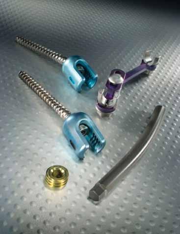
3 Introduction HydraLok Polyaxial Pedicle Screw System is a 6.0mm top-loading system that includes screws, rods and connectors that may be used in the thoracic, lumbar and sacral spine. HydraLok offers a complete range of titanium color-coded pedicle screws from 5.0mm to 8.0mm and 35mm to 55mm lengths. The 360-degree head rotation and 45-degree screw angulation allow for easy rod placement with minimal contouring. The system also features self-tapping screws that are designed to save valuable time in the operating room. 1


4 OPERATIVE TECHNIQUE OVERVIEW 1 Establish Pedicle Entry Point 2 Probe the Pedicle Ensure Integrity of Pedicle Wall 3 4 4a Mark the Pedicle 5 Tap the Pedicle 6 Load Pedicle Screw 2


5 7 Insert Polyaxial Screw 8 Place Rod and Tighten 9 Derotate Rod 10 Compression/Distraction and Final Tightening 11 Apply Cross Connectors 12 Final Tightening of Cross Connectors 3

6 DETAILED OPERATIVE TECHNIQUE LOCATE AND PREPARE THE PEDICLE Identify the pedicle and the entry hole location. The pedicle is typically located at the intersection of the superior articulate facet and the midline of the transverse process. Create an entry hole for the pedicle screw by using the Bone Awl to puncture the cortex. With the Bone Awl, penetrate the cortex by using a downward twisting force (Figure 1). Figure 1 Establish Pedicle Entry Point PROBE THE PEDICLE The Straight or Curved Pedicle Probe is used to create the screw path through the pedicle and into the vertebral body. Both of these instruments include depth markings at the tip of the instrument (Figure 2). ENSURE THE INTEGRITY OF THE PEDICLE WALL After the pedicle has been cannulated, the pedicle may now be sounded. Using the Straight Tester, verify the integrity of the interior pedicle walls by palpating the cephalad edge, the medial wall and the inferior edge as well as the deepest portion of the opening (Figure 3). GUIDE PIN INSERTION (OPTIONAL) Guide Pins are available and may be inserted to confirm the pedicle location under visualization if desired (Figure 4, 4a). Figure 2 Probe the Pedicle Figure 3 Ensure Integrity of Pedicle Wall Figure 4 Mark the Pedicle Figure 4a Mark the Pedicle 4


7 Figure 5 Tap the Pedicle Figure 6 Load Pedicle Screw TAPPING (OPTIONAL) All Polyaxial Screws are self-tapping. If pretapping is desired, Taps are available in various sizes that correspond to the diameters of the Polyaxial Screws. The Tap that is used must match the size of the Polyaxial Screw that is desired. The Taps are downsized approximately.5mm to provide an interface for the Screw. Attach the appropriately sized Tap to the Straight or Ratcheting T-Handle and proceed to tap the Screw entry hole by rotating the handle clockwise. The Depth Gauge may be used to determine Screw length (Figure 5). LOAD POLYAXIAL SCREW After determining the appropriate Screw length, attach the Reversible Polyaxial Screwdriver into the inner hexalobe of the Screw and lock it by rotating the central locking wheel clockwise. Note: It is important to note that there are two configurations for the Reversible Polyaxial Screwdriver. Use the small Reversible Drive Shaft for 5, 6 and 7mm screws and the Large Reversible Drive Shaft for the 7.5 and 8.0 Screws (Figure 6). INSERT POLYAXIAL SCREW Figure 7 Insert Polyaxial Screw into Vertebral Body The Polyaxial Screws may now be inserted into pedicle to the pre-determined depth. Turn the Reversible Polyaxial Screwdriver clockwise to insert the Screw (Figure 7). Once the Screw is fully inserted, disengage the Screw from the Reversible Polyaxial Screwdriver by turning the central locking wheel counterclockwise. Repeat the steps for all remaining Pedicle Screws. 5

8 REDUCTION SCREWS If necessary, Reduction Polyaxial Screws are also available and can be inserted using the Reversible Reduction Polyaxial Screwdriver corresponding to the desired screw size. The small Reversible Polyaxial Screwdriver is inserted into the Screw tulip and tightened by rotating the central locking wheel clockwise. ROD SELECTION After the Polyaxial Screws have been placed, the desired length of the rod should be selected. The Curved Rods are in pre-cut lengths ranging from 40mm to 110mm. The Straight Rods are available in pre-cut lengths ranging from 120mm to 480mm. ROD BENDER The French Rod Bender is primarily used for curving or bending Straight Rods. If needed, it can also be used to increase or decrease the lordosis in the Curved Rod. Figure 8 Place Rod and Tighten The degree of lordosis can be varied by adjusting the center button. A small, medium or large radius may be selected by pulling out the large center knob while rotating the knob as desired. The Rod should seat fully into the tulip of the Pedicle Screw. Note: In Situ Benders may also be used to bend the Rod once it is placed within the construct. ROD PLACEMENT AND TIGHTENING After the Rod has been contoured as desired, it is then placed into the Polyaxial Screw housing with the Curved or Straight Rod Holder (Figure 8). The Polyaxial Screw allows up to 45 degrees of angulation. Once the Rod has been placed, load a set screw onto the Twist Tip Set Screwdriver and provisionally tighten each screw. Figure 9 Derotate Rod ROD REDUCTION To assist with the reduction of the Rod into the Screw, several instruments are available. 1. The Rod Pusher helps to persuade the Rod into the Screw head, without capturing the Screw head. 2. The Pistol Grip Rod Persuader is inserted over the Rod and Screw, and the Ratcheting Handle allows the Rod to be slowly reduced. 3. The Cylinder Style Rod Persuader is used to fully capture the Polyaxial Screw head in place, while the Ratcheting Handles reduce the Rod. After the Rod is fully reduced into the Screw head, it can be provisionally tightened using the Set Screw Starter as described above. 6
.")

9 Figure 10 Compression/Distraction and Final Tightening DEROTATION, COMPRESSION AND DISTRACTION (OPTIONAL) After all of the Set Screws have been provisionally inserted into the Screw housing, the De-rotator may be used to rotate the contoured Rod into the desired position (Figure 9). While the Rod is held in place with the De-rotator, the Set Screws are tightened using the Set Screwdriver attached to the T-Handle Torque Limiting Driver. The Compressor or Distractor can also be used to apply final compression or distraction to the construct. Once the desired compression or distraction is accomplished, the Set Screws can be tightened using the Set Screwdriver attached to the T-Handle Torque Limiting Driver (Figure 10). Figure 11 Apply Cross Connector Counter TORQUE AND FINAL TIGHTENING After any desired derotation, compression and distraction have been performed; the Set Screwdriver should be attached to the T-Handle Torque Limiting Driver and inserted through the Counter Torque for final tightening of the Set Screws (Figure 10). The Set Screw should be rotated clockwise until the arrows on the torque indicator are aligned with one another, indicating the necessary torque has been applied. CROSS CONNECTOR PLACEMENT A Cross Connector may now be used if desired. Cross Connectors are available in sizes ranging from 30 to 40mm in 5mm increments and in 40 to 70mm in 10mm increments. The Cross Connector is attached to the longitudinal rods either by hand or by using the Cross Connector Nut Starter. The Crosslink Nut Starter snaps around the arm of the Cross Connector underneath the connector nut (Figure 11). This leaves the nut and rod clamp portion of the Connector free to rotate for proper positioning over the construct. Figure 12 Final Tightening of Cross Connector The Connector is pushed down until the rod clamp mechanism clicks onto the rod. Once positioned onto both rods, the Cross Connector Torque Limiting Wrench is connected to the Nut Driver and inserted through the Cross Connector Counter Torque to tighten all the nuts. The Torque Limiting Wrench should be rotated clockwise until the Handle clicks indicating that the necessary torque has been applied (Figure 12). 7


10 implant Listing Catalog Number Part Description Cross Connectors Cross Connector, 30mm-35mm Cross Connector, 35mm-40mm Cross Connector, 40mm-50mm Cross Connector, 50mm-60mm Cross Connector, 60mm-70mm Curved Rods Curved Rod, 6.0mm x 40mm Curved Rod, 6.0mm x 50mm Curved Rod, 6.0mm x 60mm Curved Rod, 6.0mm x 70mm Curved Rod, 6.0mm x 80mm Curved Rod, 6.0mm x 90mm Curved Rod, 6.0mm x 100mm Curved Rod, 6.0mm x 110mm Straight Rods Straight Rod, 6.0mm x 120mm Straight Rod, 6.0mm x 200mm Straight Rod, 6.0mm x 480mm Set Screws Set Screws, 5.0mm, 6.0mm and 7.0mm Set Screws, 7.5mm and 8.0mm Reduction Screws PS60040R PS60045R PS60050R PS70040R PS70045R PS70050R Reduction Polyaxial Screw, 6.0mm x 40mm Reduction Polyaxial Screw, 6.0mm x 45mm Reduction Polyaxial Screw, 6.0mm x 50mm Reduction Polyaxial Screw, 7.0mm x 30mm Reduction Polyaxial Screw, 7.0mm x 45mm Reduction Polyaxial Screw, 7.0mm x 50mm 8

11 Catalog Number Part Description Polyaxial Screws PS50035 PS50040 PS50045 PS50050 PS60035 PS60040 PS60045 PS60050 PS60055 PS70035 PS70040 PS70045 PS70050 PS70055 PS75035 PS75040 PS75045 PS75050 PS75055 PS80035 PS80040 PS80045 PS80050 PS80055 Polyaxial Screw, 5.0mm x 35mm Polyaxial Screw, 5.0mm x 40mm Polyaxial Screw, 5.0mm x 45mm Polyaxial Screw, 5.0mm x 50mm Polyaxial Screw, 6.0mm x 35mm Polyaxial Screw, 6.0mm x 40mm Polyaxial Screw, 6.0mm x 45mm Polyaxial Screw, 6.0mm x 50mm Polyaxial Screw, 6.0mm x 55mm Polyaxial Screw, 7.0mm x 35mm Polyaxial Screw, 7.0mm x 40mm Polyaxial Screw, 7.0mm x 45mm Polyaxial Screw, 7.0mm x 50mm Polyaxial Screw, 7.0mm x 55mm Polyaxial Screw, 7.5mm x 35mm Polyaxial Screw, 7.5mm x 40mm Polyaxial Screw, 7.5mm x 45mm Polyaxial Screw, 7.5mm x 50mm Polyaxial Screw, 7.5mm x 55mm Polyaxial Screw, 8.0mm x 35mm Polyaxial Screw, 8.0mm x 40mm Polyaxial Screw, 8.0mm x 45mm Polyaxial Screw, 8.0mm x 50mm Polyaxial Screw, 8.0mm x 55mm instrument listing Straight Probe Curved Probe Straight Tester Guide Pin Driver Guide Pin Guide Pin, Grooved Depth Gauge 9


12 HYDRALOK instrument Listing Catalog Number Part Description Hydralok 5.0mm Tap HydraLok 6.0mm Tap HydraLok 7.0mm Tap HydraLok 7.5mm Tap HydraLok 8.0mm Tap mm Hex Driver mm Hex Driver Straight Rod Holder Rod Pusher Curved Rod Holder De-rotator French Rod Bender Distractor Compressor 10


13 Catalog Number Part Description Modular Straight Handle Modular T-Handle Ratchet T-Handle Polyaxial Driver Assay Small Driver, mm screws Large Driver, 7.5mm and 8.0mm screws T-Handle and Torque Limiting Driver Counter Torque Head Positioner In Situ Bender, Left In Situ Bender, Right Counter Torque, Cross Connector Cross Connector Nut Driver Cross Connector Torque Limiting Driver Handle Curved Probe Small Polyaxial Driver Assembly 11


14 Catalog Number Part Description Bone Awl Large Polyaxial Pedicle Screw Driver Cross connector Nut Starter Crosslink Nut Driver Persuader, Pistol Grip Persuader, Cylinder Style Yoke Manipulator Tap Breaker, Reduction Screw HydraLok Implant Tray # HydraLok 5.0mm Pedicle Screw Caddy HydraLok 6.0mm Pedicle Screw Caddy HydraLok 7.0mm Pedicle Screw Caddy HydraLok 7.5mm Pedicle Screw Caddy 12


 of the L5-S1 vertebra,")
15 HydraLok 8.0mm Pedicle Screw Caddy HydraLok Implant Tray # HydraLok Reduction Pedicle Screw Caddy HydraLok Set Screw Caddy HydraLok 6.0mm Cross Connector Caddy Double Height Outer Cast Outer Case Lid Indications for Use GENERAL DESCRIPTION The HydraLok System is a top-loading spinal fixation system including screws, rods, and connectors for fixation to the thoracic, lumbar and sacral spine. Various sizes of the implants are provided. The components are manufactured from titanium alloy (Ti-6AI-4V ELI as described by ASTM F136). The HydraLok System components are provided clean and non-sterile. The products must be steam sterilized by the hospital prior to use. INDICATIONS FOR USE The HydraLok System is intended to provide immobilization and stabilization of spinal segments as an adjunct to fusion in the treatment of the following acute and chronic instabilities or deformities of the thoracic, lumbar and sacral spine including degenerative spondylolisthesis with objective evidence of neurological impairment, fracture, dislocation, scoliosis, kypohsis, spinal tumor and failed previous fusion (pseudoarthrosis). In addition, when used as a pedicle screw fixation system, the HydraLok System is intended for skeletally mature patients with severe spondylolisthesis (Grades 3 and 4) of the L5-S1 vertebra, who are receiving fusion by autogenous bone graft only having the device attached to the lumbar and sacral spine (L3 and below), who are having the device removed after the development of a solid fusion. CONTRAINDICATIONS Contraindications for the HydraLok System are similar to those of other systems of similar design, and include, but are not limited to: Active infectious process in the patient, particularly in or adjacent to the spine or spinal structures Morbid obesity 13 (continued on back)
16 Indications for Use (cont.) Pregnancy Grossly distorted anatomy (e.g., congenital abnormalities) and bone abnormalities (e.g., bone absorption, osteopenia, or osteoporosis) preventing safe screw fixation Any medical or surgical condition which would preclude the potential benefit of spinal implant surgery Suspected or documented metal allergy or intolerance WARNINGS AND PRECAUTIONS The HydraLok System should only be implanted by experienced spinal surgeons with specific training in the use of this pedicle screw spinal system because this is a technically demanding procedure presenting a risk of serious injury to the patient. In addition, based on the fatigue test results, the surgeon should consider the levels of implantation, patient weight, patient activity level, and other patient conditions (e.g., smoking, occupation), which may impact on the performance of the system. Due to the presence of implants, interference with roentgenographic, CT, and/or MR imaging will result. The HydraLok System has not been evaluated for safety and compatibility in the MR environment. The HydraLok System has not been tested for heating or migration in the MR environment. Preoperative A successful result is not achieved in every surgical case, especially in spinal surgery where many extenuating circumstances may compromise results. Preoperative planning and operating procedures, including knowledge of surgical techniques, proper reduction, and proper selection and placement of the implant are critical considerations in achieving a successful result. Only patients that meet the criteria described in the indications should be selected. Patient conditions and/or predispositions such as those mentioned in the contraindications should be avoided. The safety and effectiveness of pedicle screw spinal systems have been established only for spinal conditions with significant mechanical instability or deformity requiring fusion with instrumentation. These conditions are significant mechanical instability or deformity of the thoracic, lumbar, and sacral spine secondary to severe spondylolisthesis (grades 3 and 4) of the L5-S1 vertebra, degenerative spondylolisthesis with objective evidence of neurological impairment, fracture, dislocation, scoliosis, kyphosis, spinal tumor, and failed previous fusion (pseudoarthrosis). The safety and effectiveness of these devices for any other conditions are unknown. Care should be used in the handling and storage of the implant components. The implants should not be scratched or otherwise damaged. Implants and instruments should be protected during storage, especially from corrosive environments. The type of construct to be assembled for the case should be determined prior to beginning the surgery. An adequate inventory of sizes should be available at the time of surgery, including sizes larger and smaller than those expected to be used. Since mechanical parts are involved, the surgeon should be familiar with the various components before using the equipment and should personally assemble the devices to verify that all parts and necessary instruments are present before the surgery begins. All components and instruments must be cleaned and sterilized prior to use. Additional sterile components should be available in case of unexpected need. Intraoperative The surgeon should follow established practices and specific instructions for implant of the system. Contouring or bending of a screw may reduce its fatigue strength and cause failure under load. If screws are bent or damaged during insertion or adjustment, they may not be implanted and must be replaced. Rods should only be contoured with the proper contouring instruments. Incorrectly contoured rods or rods which have been repeatedly or excessively contoured should not be implanted. Bone grafts must be placed in the area to be fused. Some degree of corrosion occurs on all implanted metal and alloys. Mixing of dissimilar metals can accelerate the corrosion process. Stainless steel and titanium implants must NOT be used together in building a construct. Different manufacturers use different materials, varying tolerances and design configurations. Components of the HydraLok System must not be used with components from any other system or manufacturer. Postoperative The physician's post-operative directions and warnings to the patient and the corresponding patient compliance are extremely important. Detailed instructions on the use and limitations of the device should be given to the patient. The patient should be instructed to limit and restrict physical activities, especially lifting and twisting motions and any type of sport participation. Patients should be advised of their inability to bend at the point of spinal fusion and taught to compensate for this permanent restriction in body motion. The patient should be advised not to smoke or consume alcohol during the bone graft healing process. If a non-union develops or the components loosen, bend, and/or break, the device(s) should be revised and/or removed immediately before serious injury occurs. Failure to immobilize a delayed or nonunion of bone will result in excessive and repeated stresses on the implant. By the mechanism of fatigue these stresses can cause eventual bending, loosening or breakage of the device(s). Any decision to remove the implants should take into consideration the risk to the patient of additional surgeries, as well as the difficulty of removal. Any retrieved devices should be treated in such a manner that reuse in another surgical procedure is not possible. As with all orthopedic implants, none of the HydraLok System components should be reused under any circumstances. Exactech is proud to have offices and distributors around the globe. For more information about Exactech products available in your country, please visit For additional device information, refer to the Exactech Spine Instructions for Use for a device description, indications, contraindications, precautions and warnings. For further product information, please contact Customer Service, Exactech, Inc., 2320 NW 66th Court, Gainesville, Florida , USA. (352) , (800) or FAX (352) The products discussed herein may be available under different trademarks in different countries. All copyrights, and pending and registered trademarks, are property of Exactech, Inc. This material is intended for the sole use and benefit of the Exactech sales force and physicians. It should not be redistributed, duplicated or disclosed without the express written consent of Exactech, Inc Exactech, Inc EXACTECH Rev. A HyrdraLok Op. Tech *+$ *
Table of Contents.
 surgical technique The Ambassador TM Anterior Cervical Plate System is a versatile system of implants and instruments with a variety of sizes to provide optimal anatomic compatibility. The integrated cam
Y o u r Id e a s En g i n e e r e d t o Li f e
 ISSYS LP Spinal Fixation System Surgical Guide Y o u r Id e a s En g i n e e r e d t o Li f e In t r o d u c t i o n ISSYS LP Sp i n a l Fixation System The foundation of the ISSYS LP Spinal Fixation System
Valencia Pedicle Screw Surgical Technique
 Valencia Pedicle Screw Surgical Technique VALENCIA CIRCUIT TABLE OF CONTENTS Design Rationale Indications for Use Surgical Technique 1. Pedicle Preparation 2. Screw Insertion 3. Rod Placement 4. Locking
VTI INTERLINK PEDICLE SCREW SYSTEM
 VTI INTERLINK PEDICLE SCREW SYSTEM SURGICAL TECHNIQUE FORWARD THINKING FOR THE BACK. DEVICE DESCRIPTION The VTI InterLink Pedicle Screw System is comprised of polyaxial pedicle screws in various diameters
Threshold Pedicular Fixation System Surgical Technique
 Threshold Pedicular Fixation System Surgical Technique Table of Contents Patient Preparation and Positioning... 2 Determining Incision Location... 3 Assembling the Cannulated Awl... 4 Guide Wire Placement...
EXCELLA ll. Spinal System
 EXCELLA ll Spinal System Excella II Spinal System INDICATIONS FOR USE The Innovasis Excella II Spinal System is intended for use in the non-cervical area of the spine. WARNING: The safety and effectiveness
EXACTECH SPINE. Operative Technique. Cervical Spacer System. Surgeon focused. Patient driven. TM
 EXACTECH SPINE Operative Technique Cervical Spacer System Surgeon focused. Patient driven. TM ACAPELLA ONE Acapella One Cervical Spacer System is an anterior cervical discectomy and fusion device with
X-spine Surgical Technique
 X-spine Surgical Technique The X90 Pedicle Screw System Revolutionary Design and Function This document is intended exclusively for experts in the field, particularly physicians, and is not intended for
 Visit our website on www.biotech-medical.com The DLP - Dorso-Lumbar Polyaxial Screw System has been designed to address the pathologies of the thoracolumbar spine. The DLP System contains a wide range
TiLock 2 Spinal System. Surgical Technique
 TiLock 2 Spinal System Surgical Technique Table of Contents Page Preoperative Planning 4 Pedicle Preparation 5 Probe 5 Tap Pedicle 6 Screw Options 7 Screw Insertion 8 Aligning the Windows 9 Rod Insertion
A U X I L I A R Y C O N N E C T O R S Surgical Technique
 A U X I L I A R Y C O N N E C T O R S Surgical Technique AUXILIARY CONNECTORS ISSYS LP Auxiliary Connectors The ISSYS LP auxiliary connectors were designed to provide medial-lateral variability for the
Zimmer Anterior Buttress Plate System. Surgical Technique
 Zimmer Anterior Buttress Plate System Surgical Technique 2 Zimmer Anterior Buttress Plate System Surgical Technique Zimmer Anterior Buttress Plate System Surgical Technique Description, Indications & Contraindications...
Royal Oak Cervical Plate System
 Royal Oak Cervical Plate System Manufactured by Nexxt Spine, Inc. Royal Oak Cervical Plate System INTRODUCTION FEATURES AND BENEFITS Table of Contents SURGICAL TECHNIQUE Step 1. Patient Positioning Step
Dymaxeon Spine System. Simple, Streamlined, Smart. Surgical Procedure
 Simple, Streamlined, Smart Surgical Procedure Introduction The Dymaxeon pedicle screw system offers the spinal surgeon an outstanding system for stabilization of spinal deformity, reduction of spondylolisthesis,
SURGICAL TECHNIQUE GUIDE TRESTLE. Anterior Cervical Plating System
 SURGICAL TECHNIQUE GUIDE TRESTLE Anterior Cervical Plating System 2 SURGICAL TECHNIQUE GUIDE SURGICAL TECHNIQUE GUIDE System Features Large window enables visualization of graft site and end plates Screw
Ref: Q400-09T1 EBI Spine. September 05/VS02. c/o BIOMET Spain Orthopaedics, S.L.
 Ref: Q400-09T1 EBI Spine. September 05/VS02 c/o BIOMET Spain Orthopaedics, S.L. www.ebimedical.com EBI Omega 21 TM LP Since its introduction in 1996, and with thousands of patients treated so far, the
Thunderbolt. surgical technique. MIS Pedicle Screw System. Where Nimble and Secure Intersect
 Thunderbolt TM MIS Pedicle Screw System Where Nimble and Secure Intersect surgical technique i www.choicespine.com System Features Dovetail set screw: Minimizes head splay and cross-threading Secure connection
The Most Reliable Spinal Solution
 MFG : 09.02.20 REV : 1 4CIS VANE introduces you the reliable pedicle screw The Most Reliable Spinal Solution Non-slip threaded joint Ergonomic design Wedged trapezoid thread Superior locking mechanism
TM TM Surgical Technique
 TM TM Surgical Technique TABLE OF CONTENTS Reli SP Spinous Plating System Overview Device Description Implant Features Indications Instruments Access Instruments Preparation Instruments Insertion Instruments
ACP. Anterior Cervical Plate System SURGICAL TECHNIQUE
 ACP Anterior Cervical Plate System SURGICAL TECHNIQUE ACP TABLE OF CONTENTS INTRODUCTION 4 INDICATIONS AND CONTRAINDICATIONS 5 WARNINGS AND PRECAUTIONS 6 IMPLANT DESCRIPTION 7 INSTRUMENTS 10 SURGICAL
SURGICAL TECHNIQUE GUIDE SOLANAS. Posterior Cervico-Thoracic Fixation System Adjustable Bridge System
 SURGICAL TECHNIQUE GUIDE SOLANAS Posterior Cervico-Thoracic Fixation System Adjustable Bridge System 2 SURGICAL TECHNIQUE GUIDE Preface SOLANAS Posterior Cervico-Thoracic Fixation System is designed to
nva Anterior Lumbar Interbody Fusion System
 nva Anterior Lumbar Interbody Fusion System 1 IMPORTANT INFORMATION FOR PHYSICIANS, SURGEONS, AND/OR STAFF The nv a, nv p, and nv t are an intervertebral body fusion device used in the lumbar spine following
nvt Transforaminal Lumbar Interbody Fusion System
 nvt Transforaminal Lumbar Interbody Fusion System 1 IMPORTANT INFORMATION FOR PHYSICIANS, SURGEONS, AND/OR STAFF The nv a, nv p, and nv t are an intervertebral body fusion device used in the lumbar spine
SURGICAL TECHNIQUE. SECURIS Pedicle Screw System for Minimally Invasive Surgery. 2 I SECURIS Pedicle Screw System
 Surgical Technique e Guide SECURIS Pedicle Screw System for Minimally Invasive Surgery Securis Pedicle Screw System has been engineered to provide temporary posterior stabilization of the thoracolumbar
Cervical Spacer System surgical technique
 Blackhawk TM Cervical Spacer System surgical technique Blackhawk TM The BLACKHAWK Cervical Spacer System is designed to provide biomechanical stabilization as an adjunct to fusion. Spinal fixation should
nvp Posterior Lumbar Interbody Fusion System
 nvp Posterior Lumbar Interbody Fusion System 1 IMPORTANT INFORMATION FOR PHYSICIANS, SURGEONS, AND/OR STAFF The nv a, nv p, and nv t are an intervertebral body fusion device used in the lumbar spine following
TiLock XT Minimally Invasive Surgery (MIS) Pedicle Screw System
 Pedicle Screw System") TiLock XT Minimally Invasive Surgery (MIS) Pedicle Screw System The Genesys Spine TiLock XT Minimally Invasive Surgery (MIS) Pedicle Screw System consists of rods (straight and curved), lock screws, and
TiLock XT Minimally Invasive Surgery (MIS) Pedicle Screw System The Genesys Spine TiLock XT Minimally Invasive Surgery (MIS) Pedicle Screw System consists of rods (straight and curved), lock screws, and
USS Variable Axis Screw (VAS) System. For posterior fixation of the lumbar spine.
 System. For posterior fixation of the lumbar spine.") USS Variable Axis Screw (VAS) System. For posterior fixation of the lumbar spine. Technique Guide Instruments and implants approved by the AO Foundation Table of Contents Introduction USS Variable Axis
USS Variable Axis Screw (VAS) System. For posterior fixation of the lumbar spine. Technique Guide Instruments and implants approved by the AO Foundation Table of Contents Introduction USS Variable Axis
HawkeyeTM Peek. surgical technique
 HawkeyeTM Peek surgical technique Introduction The ChoiceSpine HAWKEYE Vertebral Body Replacement (VBR) System is intended for use in the thoracolumbar spine (T1 - L5) to replace a collapsed, damaged,
O PE RATIV E TE C HN IQ U E. Minimally Invasive Posterior Fixation
 O PE RATIV E TE C HN IQ U E TM Minimally Invasive Posterior Fixation Table of Contents 1 PRE-OPERATIVE PLANNING Patient Positioning Pedicle Identification and Incision Planning 4 OPERATIVE TECHNIQUE Incision
Zimmer Facet Screw System Surgical Technique
 Zimmer Facet Screw System Surgical Technique 2 Zimmer Facet Screw System Surgical Technique Zimmer Facet Screw System Surgical Technique Description, Indications & Contraindications...3 Surgical Technique...4
Veyron -C Anterior Cervical System Surgical Technique
 Veyron -C Anterior Cervical System Surgical Technique 2 Veyron-C Anterior Cervical System Surgical Technique Veyron-C Anterior Cervical System Surgical Technique Description, Indications & Contraindications...3
TiLock XT Minimally Invasive Surgery (MIS) Pedicle Screw System
 Pedicle Screw System") Minimally Invasive Surgery (MIS) Pedicle Screw System Surgical Technique Guide 2 Minimally Invasive Surgery (MIS) Pedicle Screw System The Genesys Spine Minimally Invasive Surgery (MIS) Pedicle Screw System
Minimally Invasive Surgery (MIS) Pedicle Screw System Surgical Technique Guide 2 Minimally Invasive Surgery (MIS) Pedicle Screw System The Genesys Spine Minimally Invasive Surgery (MIS) Pedicle Screw System
ACP1 CERVICAL PLATE SPINAL SYSTEM SURGICAL TECHNIQUE GUIDE II.
 I. ACP1 CERVICAL PLATE II. SPINAL SYSTEM SURGICAL TECHNIQUE GUIDE I. Introduction The Gold Standard Orthopaedics, LLC ACP1 Spinal System was designed with surgeons to incorporate strength, functionality,
100 Interpace Parkway Parsippany, NJ
 100 Interpace Parkway Parsippany, NJ 07054 www.biometspine.com 800-526-2579 All trademarks are the property of Biomet, Inc. or one of its subsidiaries, unless otherwise indicated. Rx Only. 2009 EBI, LLC.
Technique Guide. Universal Spinal System (USS). Designed to achieve the goals of scoliosis surgery.
. Designed to achieve the goals of scoliosis surgery.") Technique Guide Universal Spinal System (USS). Designed to achieve the goals of scoliosis surgery. Table of Contents Introduction Universal Spinal System 2 AO ASIF Principles of Internal Fixation 3 Indications
Technique Guide Universal Spinal System (USS). Designed to achieve the goals of scoliosis surgery. Table of Contents Introduction Universal Spinal System 2 AO ASIF Principles of Internal Fixation 3 Indications
Surgical Technique. Available In Titanium And Stainless Steel
 Surgical Technique Available In Titanium And Stainless Steel Contents Introduction... Page 1 System Design Features... Page 2 Implants... Page 3 Standard Instruments... Page 7 Degenerative Surgical Technique...
Surgical Technique FOR U.S. DOMESTIC USE ONLY
 Surgical Technique FOR U.S. DOMESTIC USE ONLY Polyaxial Screws HA Coated Polyaxial Screws Uniplanar Screws Reduction Screws Reduction Uniplanar Screws Modular Screws TABLE OF CONTENTS Reform Pedicle Screw
L8 Spine System SURGICAL TECHNIQUE. Add: No.1-8, Tianshan Road, Xinbei District, Changzhou, Jiangsu, China
 Add: No.-8, Tianshan Road, Xinbei District, Changzhou, Jiangsu, China 23022 Tel: 0086 59 8595556 Fax: 0086 59 859555 Http://www.kanghui.com Add: F25, Shanghai International Pharmaceutical Trad & Exhibition
OPERATIVE TECHNIQUE. anterior cervical plating system
 OPERATIVE TECHNIQUE 3º anterior cervical plating system Introduction 1 Pre-Operative Technique 2 Oerative Technique 3 Instructions for Use 12 Part Numbers 16 The surgical technique shown is for illustrative
EXPEDIUM 5.5 Spine System Family Product Catalogue
 EXPEDIUM 5.5 Spine System Family Product Catalogue Including: EXPEDIUM EXPEDIUM Vertebral Body Derotation Universal Connector Set Cobalt Chromium Rods INTRODUCTION Contents EXPEDIUM Spine System is a comprehensive
LBL-014. Rev
 Package Insert Z- CLAMP ISP System Device Description: The Z-CLAMP ISP System is supplemental fixation device consisting of a variety of shapes and sizes of one-level lumbar and sacral plates and screws.
ONE SYSTEM, MULTIPLE OPTIONS. Surgical Technique. Hip Knee Spine Navigation
 ONE SYSTEM, MULTIPLE OPTIONS Surgical Technique Hip Knee Spine Navigation MUST MINI Surgical Technique Hip Knee Spine Navigation INTRODUCTION The M.U.S.T. Mini posterior cervical screw system is a modular
SerratoTM. Surgical technique
 TM Surgical technique Table of contents Key design features.... 3 System overview.... 4 Surgical technique Patient positioning... 7 Preparing the pedicle.... 8 Screw insertion... 11 Rod contouring... 12
INTELLIGENT SPINAL SYSTEM
 INTELLIGENT SPINAL SYSTEM I. Introduction II. Product Specification III. Surgical Technique IV. Ordering Information V. IFU for Lospa IS SPINAL SYSTEM The LOSPA IS spinal system consists of
ASFORA ANTERIOR CERVICAL PLATE SYSTEM (AACP) SURGICAL PROCEDURE MANUAL
 SURGICAL PROCEDURE MANUAL") ASFORA ANTERIOR CERVICAL PLATE SYSTEM (AACP) SURGICAL PROCEDURE MANUAL Contents: Introduction Indications Contraindications Warnings Precautions Implant Overview Instruments Overview Surgical Technique
ASFORA ANTERIOR CERVICAL PLATE SYSTEM (AACP) SURGICAL PROCEDURE MANUAL Contents: Introduction Indications Contraindications Warnings Precautions Implant Overview Instruments Overview Surgical Technique
Lapidus Arthrodesis System Instructions for Use
 Lapidus Arthrodesis System Instructions for Use Description The AlignMATE Lapidus Arthrodesis System consists of bone plates and bone screws (locking, non-locking and interfragmentary), which are intended
Handling instructions. USS Low Profile. Thoracolumbar posterior fixation system.
 Handling instructions USS Low Profile. Thoracolumbar posterior fixation system. U Table of contents Introduction Indications and contraindications 3 USS Low Profile implants 4 Handling implants with stick
TABLE OF CONTENTS. Vault C Anterior Cervical Discectomy 2 and Fusion (ACDF) System Overview. Implants 3. Instruments 5. Surgical Technique 10
 System Overview. Implants 3. Instruments 5. Surgical Technique 10") Surgical Technique TABLE OF CONTENTS Vault C Anterior Cervical Discectomy 2 and Fusion (ACDF) System Overview Indications 2 Implants 3 Instruments 5 Surgical Technique 10 1. Preoperative planning 10 2.
Surgical Technique TABLE OF CONTENTS Vault C Anterior Cervical Discectomy 2 and Fusion (ACDF) System Overview Indications 2 Implants 3 Instruments 5 Surgical Technique 10 1. Preoperative planning 10 2.
operative technique Universal Application
 operative technique Universal Application Introduction Introduction Building upon the design rationale of the Xia Spinal System, the new Xia Spinal System represents the latest advancement in spinal implant
Biomet Omega21 TM Spinal Fixation System
 Biomet Omega21 TM Spinal Fixation System Surgical Technique Coronal Angulation 50% Axial Angulation Infinite Sagittal Angulation Contents Introduction... Page 1 System Design Features And Benefits... Page
AccuVision Minimally Invasive Spinal Exposure System
 Surgical Technique AccuVision Minimally Invasive Spinal Exposure System Working Beyond the Tube Lighted blades for superior viewing Maximum stabilization Contents Introduction... Page 1 Features and Benefits...
Thoracolumbar Solutions. Vital Spinal Fixation System. Degenerative. Surgical Technique Guide
 Thoracolumbar Solutions Vital Spinal Fixation System Degenerative Surgical Technique Guide 2 Vital Spinal Fixation System Surgical Technique Guide Vital Spinal Fixation System is an optimized instrument
Surgical Technique. Occipito-Cervico-Thoracic System
 OASYS Surgical Technique Occipito-Cervico-Thoracic System System Overview The OASYS Occipito-Cervico-Thoracic System was developed to provide the surgeon with versatility for the treatment of pathologies
A Fusion of Versatility, Performance and Ease.
 MATRIX Spine System. Degenerative and Deformity. System Guide A Fusion of Versatility, Performance and Ease. Instruments and implants approved by the AO Foundation The MATRIX Spine System is a universal
EXCELLA MIS. Spinal System
 EXCELLA MIS Spinal System Excella MIS Spinal System INDICATIONS FOR USE The Innovasis Excella MIS Spinal System is intended for use in the non-cervical area of the spine. WARNING: The safety and effectiveness
Ballista Percutaneous Screw Placement System
 Surgical Technique Ballista Percutaneous Screw Placement System A Minimally Invasive Approach for Posterior Spinal Surgery True percutaneous system Helical Flange locking mechanism Contents Introduction...
SURGICAL TECHNIQUE. Standard Reduction HA Coated Modular. Discover the Difference
 SURGICAL TECHNIQUE Standard Reduction HA Coated Modular Discover the Difference TABLE OF CONTENTS REFORM PEDICLE SCREW SYSTEM OVERVIEW 3 TRAY IMAGES & CONTENT 14 SURGICAL TECHNIQUE 34 1. Preoperative Planning
Ballista Percutaneous Screw Placement System. Surgical Technique
 Ballista Percutaneous Screw Placement System Surgical Technique Contents Introduction... Page 1 Features And Benefits... Page 2 Implants... Page 3 Instruments... Page 4 Surgical Technique... Page 8 Indications
Gallery Laminoplasty Spine System
 Surgical Technique Gallery Laminoplasty Spine System A smart, simple to use system with intuitive design features. Smart Plate Design Three hole, cobra head design Plates with hook or standard plates available
Cervical Screw System
 Cervical Screw System LnK Posterior Cervical Screw The LnK Cervical Fixation System provides a top-loading, simple and secure system for rigid fixation. The LnK Cervical Fixation system includes instrumentation
Technique Guide MAXIMUM ACCESS SURGICAL PLATFORM
 Technique Guide MAXIMUM ACCESS SURGICAL PLATFORM MAXIMUM ACCESS SURGICAL PLATFORM CONTENTS Preface 1 SpheRx II Anterior Technique Guide 2 Equipment Requirements 2 Patient Positioning and O.R. Setup 2 Staple
Thoracolumbar Spine Locking Plate (TSLP) System. A low-profile plating system for anterior stabilization of the thoracic and lumbar spine.
 System. A low-profile plating system for anterior stabilization of the thoracic and lumbar spine.") Thoracolumbar Spine Locking Plate (TSLP) System. A low-profile plating system for anterior stabilization of the thoracic and lumbar spine. Technique Guide Instruments and implants approved by the AO Foundation
Thoracolumbar Spine Locking Plate (TSLP) System. A low-profile plating system for anterior stabilization of the thoracic and lumbar spine. Technique Guide Instruments and implants approved by the AO Foundation
GIZA Surgical Technique
 GIZA Surgical Technique Vertebral Body Replacement System Manufactured by Titanium alloy material provides mechanical integrity during insertion and distraction, x-ray visibility, and biocompatibility*
Ascent. Surgical Technique. Breakthrough Thinking. Posterior Occipital Cervico-Thoracic (POCT) System. Germany U.S.A.
 System. Germany U.S.A.") Fusion Motion Preservation Biologics Surgical Technique Breakthrough Thinking Fusion I Motion Preservation I Biologics Posterior Occipital Cervico-Thoracic (POCT) System U.S.A. Corporate Headquarters Blackstone
Fusion Motion Preservation Biologics Surgical Technique Breakthrough Thinking Fusion I Motion Preservation I Biologics Posterior Occipital Cervico-Thoracic (POCT) System U.S.A. Corporate Headquarters Blackstone
PRODUCT SUMMARY Cobalt Chrome Tulip Multiple Options Triple Lead Thread
 PRODUCT SUMMARY Cobalt Chrome Tulip Multiple Options Triple Lead Thread Screws Low Profile 2.72 Footprint x 2.5 Height Square Threaded Locking Cap Geometry reduces risk of cross threading Hexalobular Drive
MATRIX Spine System Deformity
 A Solution for Simple and Complex Spine Pathology MATRIX Spine System Deformity Surgical Technique Image intensifier control This description alone does not provide sufficient background for direct use
2. Active systemic infection or infection localized to the site of the proposed implantation is contraindications to implantation.
 OIC Pedicle Screw System! The Orthopaedic Implant Company 316 California Ave #701 Reno, NV 89509 USA System Contents: Non-Sterile Implants Single Use Only Non-Sterile Instruments - Reusable 2 Caution:
I. II. SPINAL SYSTEM SURGICAL TECHNIQUE GUIDE
 I. GS1 II. SPINAL SYSTEM SURGICAL TECHNIQUE GUIDE Introduction The Gold Standard Orthopaedics, LLC GS1 Spinal System designed in conjunction with Richard Holt, M.D. incorporates both strength and function
POLYAXIAL SPINE SYSTEM D E G E N E R A T I V E
 S U R G I C A L T E C H N I Q U E En POLYAXIAL SPINE SYSTEM D E G E N E R A T I V E LOW PROFILE POLYAXIAL SPINE SYSTEM A01110050 Straight spatula A01110060 Curved spatula A01110070 Bone probe A01114500
Technique Guide Small Bone Fusion System
 Technique Guide Small Bone Fusion System The Pinit Plate Small Bone Fusion System is a super low profile, modular bone plate and screw system designed to stabilize a bunionectomy with a medial to lateral
Alamo T Transforaminal Lumbar Interbody System Surgical Technique
 Transforaminal Lumbar Interbody System Surgical Technique Table of Contents Indications and Device Description.............. 1 Alamo T Implant Features and Instruments...........2 Surgical Technique......................
Surgical Technique. Guide and Ordering Information. Favored Angle Screw
 Surgical Technique Guide and Ordering Information Favored Angle Screw C O N T E N T S SURGICAL TECHNIQUE Introduction 1 Screwdriver Application and Screw Placement 2 Segmental Translation 3-7 Segmental
MEDACTA UNCONSTRAINED SCREW TECHNOLOGY - REDUCTION SCREWS. Surgical Technique. Hip Knee Spine Navigation
 .U.S.T. MEDACTA UNCONSTRAINED SCREW TECHNOLOGY - REDUCTION SCREWS Hip Knee Spine Navigation M.U.S.T. Hip Knee Spine Navigation INTRODUCTION The Medacta Unconstrained Screw Technology [M.U.S.T.] Pedicle
Surgical Technique. Guide
 Surgical Technique Guide DESIGNING SURGEONS Darrel Brodke, M.D. University of Utah Medical Center Dept. of Orthopedic Surgery Salt Lake City, Utah Iain Kalfas, M.D., F.A.C.S The Cleveland Clinic Foundation
Dual-Opening USS. For deformity correction.
 Dual-Opening USS. For deformity correction. Technique Guide Instruments and implants approved by the AO Foundation Table of Contents Introduction Dual-Opening USS 2 AO Principles 4 Indications 5 Preoperative
ONE SYSTEM, MULTIPLE OPTIONS. Surgical Technique
 ONE SYSTEM, MULTIPLE OPTIONS Surgical Technique Joint Spine Sports Med M.U.S.T. Mini Surgical Technique 2 INDEX 1. INTRODUCTION 4 1.1 Indications 4 1.2 Contraindications 4 1.3 Pre-Operative Planning 5
Hinged Laminoplasty System surgical technique
 BlackbirdTM Hls Hinged Laminoplasty System surgical technique Blackbird TM Hls The ChoiceSpine Blackbird Hinged Laminoplasty System (HLS) design eliminates fitting plates through trial and error bending.
3 Operative Technique U.S. EDITION
 3 A N T E R I O R C E R V I C A L P L AT E S Y S T E M 3 Operative Technique U.S. EDITION Table of Contents 1 INTRODUCTION 2 PRE-OPERATIVE 3 OPERATIVE 12 INSTRUCTIONS FOR USE 16 PART NUMBERS Orthofix Spinal
Surgical Technique & Product Catalogue. Guide for Open & MIS Procedures
 Surgical Technique & Product Catalogue Guide for Open & MIS Procedures INTRODUCTION The VIPER Cortical Fix Fenestrated Screw System is the first pedicle screw implant to offer enhanced fixation in both
X-spine Systems, Inc. Spider Cervical Plating System
 X-spine Systems, Inc. Spider Cervical Plating System GENERAL DESCRIPTION The Spider Cervical Plating System consists of screws and plates offered in various sizes so that adaptations can be made to take
UniLink Interspinous Fusion System UniLink 5/1 Interspinous Fusion System UniLink Graft. Surgical Technique
 UniLink Interspinous Fusion System UniLink 5/1 Interspinous Fusion System UniLink Graft Surgical Technique 2 UniLink and UniLink 5/1 Interspinous Fusion System Surgical Technique UniLink and Unlink 5/1
Alamo C. Cervical Interbody System Surgical Technique. An Alliance Partners Company
 Cervical Interbody System Surgical Technique Table of Contents Indications for Use................................1 Device Description............................... 1 Alamo C Instruments..............................
Pinit Plate Small Bone Fusion System Bone Plate & Screw System
 Pinit Plate Small Bone Fusion System Bone Plate & Screw System Description The Pinit Plate Small Bone Fusion System consists of 2-hole bone plates made available in three length options and two thickness
VECTRA-T SURGICAL TECHNIQUE. The Translational Anterior Cervical Palate System. This publication is not intended for distribution in the USA.
 VECTRA-T The Translational Anterior Cervical Palate System This publication is not intended for distribution in the USA. SURGICAL TECHNIQUE Image intensifier control This description alone does not provide
USS Variable Axis Screw
 USS Variable Axis Screw Polyaxial side-opening pedicle screw Surgical technique Original Instruments and Implants of the Association for the Study of Internal Fixation AO/ASIF USS Variable Axis Screw
X-spine Systems, Inc. X90 Pedicle Screw System
 X-spine Systems, Inc. X90 Pedicle Screw System GENERAL INFORMATION The X90 Pedicle Screw System consists of rods, pedicle screws, cross bar connectors and hand instruments. Various forms and sizes of these
Surgical Technique 1
 1 Surgical Technique TELLURIDE 2 MIS SPINAL FIXATION SYSTEM The Telluride 2 MIS Spinal Fixation System is a simple, robust and versatile minimally invasive pedicle screw system consisting of implants and
Technique Guide. Pangea Spine System. Top loading pedicle screw and hook system for posterior stabilization and correction of spinal deformities.
 Technique Guide Pangea Spine System. Top loading pedicle screw and hook system for posterior stabilization and correction of spinal deformities. Table of Contents Introduction Pangea Spine System 4 Dual
Surgical Technique Guide
 Sacroiliac Joint Fusion System Surgical Technique Guide Moving Life Forward Table of Contents SiCure Implant Overview...2 SiCure System Information...3 X-ray Basics...4 Patient Positioning....5 Surgical
Cyprus Anterior Cervical Plate System. Surgical Technique
 Cyprus Anterior Cervical Plate System Surgical Technique Contents Introduction... Page 1 Design Features... Page 2 System Components... Page 3 Surgical Technique... Page 6 Additional Surgical Options...
Trinica and Trinica Select Anterior Cervical Plate System
 Surgical Technique Trinica and Trinica Select Anterior Cervical Plate System A New Twist to Anterior Cervical Plates Trinica and Trinica Select Surgical Technique 1 Trinica and Trinica Select Anterior
VERTEX SELECT. surgical technique. adjustability. Flexibility. adaptability. Reconstruction System
 VERTEX SELECT Reconstruction System surgical technique adjustability. Flexibility. adaptability. adjustability. Flexibility. adaptability. The VERTEX SELECT Reconstruction System is a comprehensive set
Spine. THOR Anterior Lumbar Plate Operative Technique
 Spine THOR Anterior Lumbar Plate Operative Technique Table of Contents THOR Anterior Lumbar Plate Surgical Technique Introduction 3 Implants 4 Instruments 5-6 Procedure 7-12 Removal of Implants 13 Indications
EXACTECH KNEE. Operative Technique ADDENDUM. Metaphyseal Cones. Surgeon focused. Patient driven. TM
 EXACTECH KNEE Operative Technique ADDENDUM Metaphyseal Cones Surgeon focused. Patient driven. TM TABLE OF CONTENTS INTRODUCTION...1 DESCRIPTION...1 DETAILED OPERATIVE TECHNIQUE Initial Preparation and
product overview Implant heights range from 8mm-20mm in 2mm increments, with two lordocic angle options of 6 and 12.
 ETHOS A-Spacer PEEK System Surgical Technique Guide Synchronizing Medical Innovation with Global Markets product overview The SyncMedical Ethos PEEK IBF System is an intervertebral body fusion device for
SMV Scientific Bone Plate and Screw System Surgical Technique
 SMV Scientific Bone Plate and Screw System Surgical Technique Description: The SMV Scientific Bone Plate and Screw System consists of non-locking plates and bone screw fasteners in a variety of lengths,
MATRIX Spine System Deformity. A posterior pedicle screw, hook, and rod fixation system.
 MATRIX Spine System Deformity. A posterior pedicle screw, hook, and rod fixation system. Technique Guide Instruments and implants approved by the AO Foundation Table of Contents Introduction MATRIX Spine
Thoracolumbar Solutions. Polaris TM Deformity System. Surgical Technique Guide
 Thoracolumbar Solutions Polaris TM 4.75 Deformity System Surgical Technique Guide 2 Polaris TM 4.75 Deformity System Surgical Technique Guide Comprehensive System Accommodates 4.5mm and 4.75mm Rods Axial
Technique Guide. USS Small Stature/Pediatric. A multifaceted deformity system for use in patients of small stature.
 Technique Guide USS Small Stature/Pediatric. A multifaceted deformity system for use in patients of small stature. Image intensifier control Warning This description alone does not provide sufficient background