System. Guide. Adaptable MIS solutions for an evolving practice
|
|
|
- Jennifer Johnson
- 6 years ago
- Views:
Transcription

1 System Guide Adaptable MIS solutions for an evolving practice
2 SURGEON DESIGNERS D. Greg Anderson, MD Thomas Jefferson University Hospital Rothman Orthopaedics Philadelphia, PA Robert Heary, MD University of Medicine & Dentistry New Jersey Newark, New Jersey Carl Lauryssen, MD Tower Orthopedic & Neurosurgical Spine Institute Beverly Hills, CA Tony Tannoury, MD Boston University Medical Center Boston, MA Professor Cornelius Wimmer, MD Behandlungszentrum Vogtareuth (Vogtareuth Treatment Center) Vogtareuth, Germany CONTRibuting SurgeonS Dirk Alander, MD John Asghar, MD Eric Belanger, MD Randal Betz, MD Ashok Biyani, MD Andrew Cannestra, MD Mitch Hardenbrook, MD Bradley Heiges, MD Marty Herman, MD Doug Linville, MD Steve Ludwig, MD Paul Park, MD Kees Poelstra, MD Khalid Sethi, MD John Shiau, MD Harry Shufflebarger, MD Jonathan Song, MD Mike Wang, MD Faissal Zahrawi, MD
3 Contents System Overview 2 Lumbar Degenerative 5 Deformity 9 Trauma 13 Tumor 17 Surgical Technique Guide 21 Product Catalog 47


4 System Overview VIPER 2, the evolution of minimally invasive spine surgery. Building upon the groundbreaking design and intuitive techniques established by the original VIPER System, VIPER 2 empowers Spine Surgeons to treat an unparalleled range of pathologies with a single platform solution. By delivering a comprehensive range of instrumentation and implant options, VIPER 2 provides surgeons with the confidence and control required to address more advanced indications with a less invasive approach. Born from EXPEDIUM, evolved from VIPER, VIPER 2 takes percutaneous fixation to the next level. DEGENERATIVE DEFORMITY

5 TUMOR TRAUMA
6 Degenerative

")


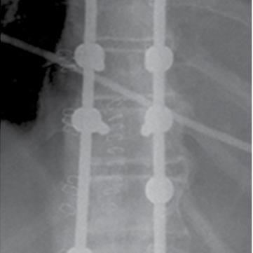
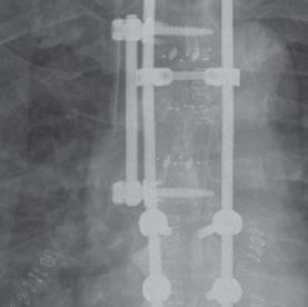
7 Percutaneous Treatment of A Degenerative Spondylolisthesis Using the VIPER 2 System DEGENERATIVE Carl Lauryssen, MD and Pablo Pazmino, MD Olympia Medical Center, Los Angeles, CA Figure 1: Flexion Figure 2: Neutral Figure 3: Extension Figure 4: Lateral Post-op X-Ray Figure 5: A-P Post-op X-Ray History of Present Illness and Imaging: 45 year old female with intense lower back and leg pain who previously underwent, L4 - S1 laminectomy and discectomy five years ago Her symptoms gradually worsened over the past 5 years and currently reports a VAS of 10 Imaging revealed a grade 1 spondylolisthesis at L5 - S1, and pars fracture at L4 - L5 with evidence of instability on flexion extension films (Figures 1, 2 & 3) Treatment Method and Materials: Two level interbody fusions were performed from an anterior approach at L4/L5 and L5/S1 The graft was secured using an AEGIS lumbar plate at L5/S1 and a buttress screw at L4/L5 The patient was flipped and posterior MIS decompression was performed using the SPOTLIGHT tubular retractor system Six VIPER pedicle screws were placed percutaneously at the L4, L5 and S1 levels Two 70mm pre-lordosed rods were placed percutaneously and once in place, the VIPER 2 reduction instrument was used to reduce the spondylolisthesis at L5 Total anesthesia time was 4 hrs and the blood loss was 100cc s Follow-up Results: Patient was discharged on post-op day three and at one week reported relief of pre-operative symptoms At three months follow up, radiographs demonstrated evidence of fusion and good alignment at operative levels (Figures 4 and 5) Presently, she reports good pain relief and has resumed nearly full job functions The VIPER 2 System provided a quick and easy-to-use option for reducing this patient s degenerative spondylolisthesis with minimal muscle trauma.


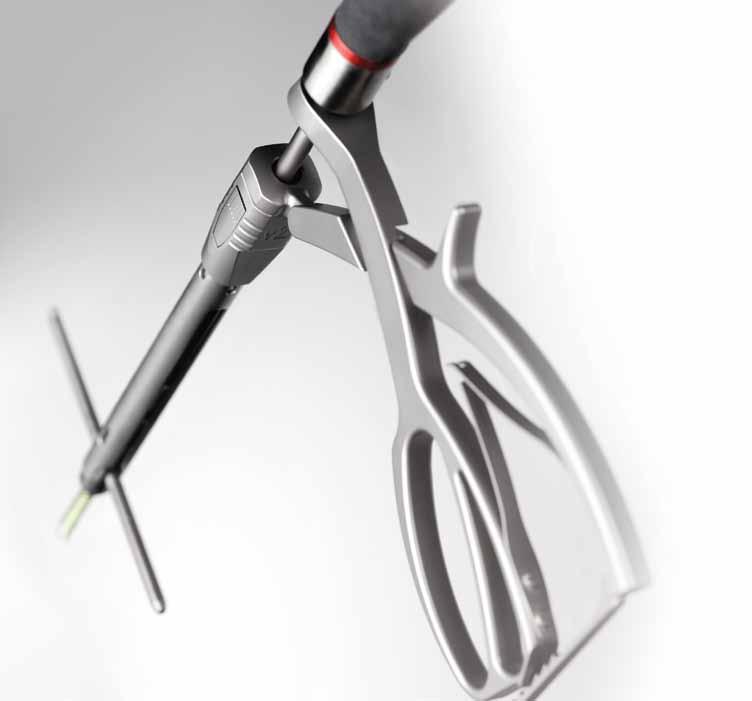
8 A Faster, Simpler Approach to Percutaneous Degenerative Fixation Streamlined Rod Placement Simple and repeatable rod placement through 2 stab incisions insert & rotate Minimal Muscle Trauma A truly percutaneous technique eliminates any unnecessary incisions and tissue trauma VIPER 2 Competitor 1 Competitor 2 6
: V2 X-Tab Implants bring integrated reduction tab")

9 system guide Simple PERCUTANEOUS Reduction Options Comprehensive internal rod reduction options to simplify even the most difficult cases without compromising incision size X-Tab Screw (Extended Tab Reduction Screw): V2 X-Tab Implants bring integrated reduction tab technology to MIS surgery 12mm outer diameter minimizes incision size Pistol-Grip Reducer: Quickly connect to any V2 Extension for easy one-step internal reduction Integrated break-off reduction tabs eliminate the need for extension assembly Simple threaded reduction 7
10 Deformity


, L4 and L5 levels Two 200mm straight VIPER 2 rods were cut and contoured using the tops of the screw extensions as a guide The rods were placed percutaneously and")
11 Percutaneous Short Segment Adult Deformity Treatment Using the VIPER 2 System D. Greg Anderson, MD Thomas Jefferson University, Department of Orthopaedics DEFORMITY Figures 1 and 2: AP and Lateral Views Figures 3 and 4: AP and Lateral Views of the Spine at the 1-year Postoperative Visit History of Present Illness and Radiographs: 57 year old male presented with a bilateral back, buttock and thigh pain and reports symptoms had progressively worsened for the last 5 years The patient had been treated with physical therapy, NSAIDS and epidural injections, but these treatments had become ineffective over last year Imaging revealed the presence of a 30º degenerative scoliotic curve in the lumbar spine (Figures 1 and 2) Treatment Method and Materials: Interbody fusions and releases of the deformity were performed at the L2 - L5 disc spaces using a lateral approach The patient was then flipped and the SPOTLIGHT tubular retractor system was used to posteriorly decompress areas of lateral recess stenosis at the L2 - L5 levels. Bilateral decortication of the facet joints for fusion was also performed at L2 - L5 at this time Using the same skin incisions, seven percutaneous VIPER pedicle screws were placed under fluoroscopic guidance at the L2, L3 (unilateral), L4 and L5 levels Two 200mm straight VIPER 2 rods were cut and contoured using the tops of the screw extensions as a guide The rods were placed percutaneously and once in place, VIPER 2 reduction and compression instruments were used to help correct the sagittal and coronal alignment The total anesthesia time for both stages of the surgery was 4.5 hrs and the blood loss was 150cc s Follow-up Results: Patient was mobilized to a chair the evening of surgery and discharged on postoperative day two By post-op week two, he reported good relief of his pre-operative symptoms and was able to resume normal work functions, including attending a conference in another state by week three At one year, radiographs demonstrated a solid fusion at all operative levels (Figures 3 and 4) Presently, he reports excellent pain relief and has resumed an active lifestyle The VIPER 2 System allows for minimally invasive treatment of adult degenerative scoliosis, while still achieving satisfactory reconstruction and alignment. The decreased muscle trauma afforded by the system allowed this patient to quickly return to normal activities without compromising long term results.


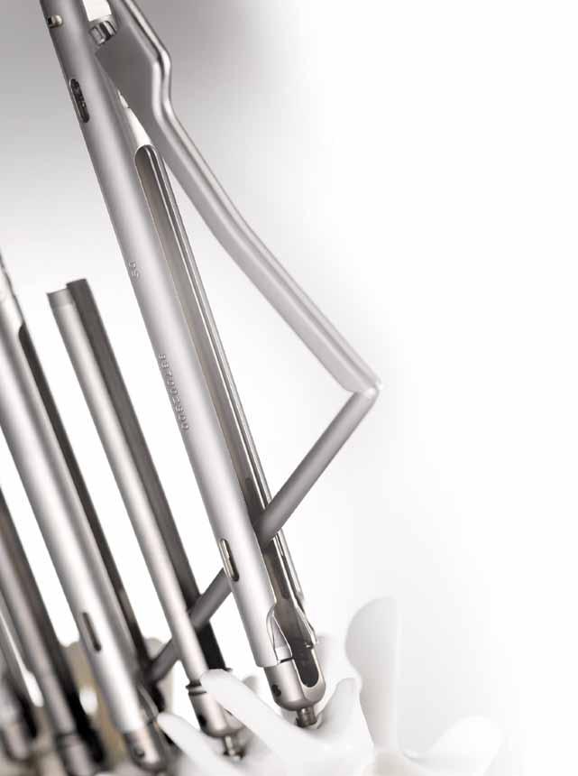
12 The Confidence to Treat Deformity with an MIS Approach Versatile & Secure Correction Solutions Connection Strength: V2 Extension & Rod Holder technology are designed to withstand the demands of deformity correction V2 extension connection strength allows for vertebral body manipulation before or after rod insertion Hex-End Rod Design: Bulleted V2 Hex-End Rod and novel connection feature provide 360º of percutaneous rod rotation control during and after rod placement 10


13 system guide Powerful Internal Approximation Options Pistol Grip Approximation provides quick, intuitive rod reduction without bulky external sleeves V2 X-Tab Screws offer the simplicity & control of integrated threaded reduction in an ultra-low profile design 12mm 15mm 22mm V2 X-Tab Screw V2 Extension Low-Profile Instrument Design V2 Extensions & X-Tab Screws designs are optimized to reduce instrument crowding and incision size for complex surgery Competitor S Extension 11
14 Trauma

 Treatment Method and Materials: An anterior corpectomy was performed at L1/ L2 and an 80mm mesh cage was inserted into the space left from")
 to L4 OR time for the posterior portion of")


15 Percutaneous Spinal Trauma Treatment Using the VIPER 2 System Tony Tannoury, MD Boston University, Department of Orthopaedics TRAUMA Figure 1: Lateral CT Scan Figure 2: Axial CT of L1 Figure 3: Axial CT of L2 Figure 4: Post-op Lateral Radiograph Figure 5: Post-op A-P Radiograph History of Present Illness and Imaging: A 48 year old male construction worker arrived at the ER after falling from a three story building The patient was neurologically intact but demonstrated signs of bilateral leg weakness Imaging revealed L1 and L2 burst fractures with a severely compromised canal at both levels (Figures 1, 2, & 3) Treatment Method and Materials: An anterior corpectomy was performed at L1/ L2 and an 80mm mesh cage was inserted into the space left from T12 to L3 A unilateral anterior EXPEDIUM rod and screw construct was inserted laterally from T12 to L3 to support the anterior column Nine percutaneous VIPER screws were placed bi-laterally at every level from T12 to L4 except in the left pedicle on L1 Bilateral 120mm VIPER 2 rods were placed percutaneously starting from T12 (Figures 4 & 5) to L4 OR time for the posterior portion of the case was approximately 75 minutes with 75cc of blood loss and no complications Follow-up Results The patient was ambulating on post-operative day three and was discharged on day four At the time of discharge, the patient reported almost no posterior muscle pain despite the 5-level instrumentation At six months post-op, the patient was back to normal function and had no signs of adjacent level degeneration or post-traumatic alignment issues The patient has no complaints of incisional or muscle pain and the skin incisions were observed to have healed completely at six months The VIPER 2 System s percutaneous posterior fixation allowed us to fully stabilize this patient s spine while contributing to little blood loss, minimal posterior muscle damage and a fast recovery.
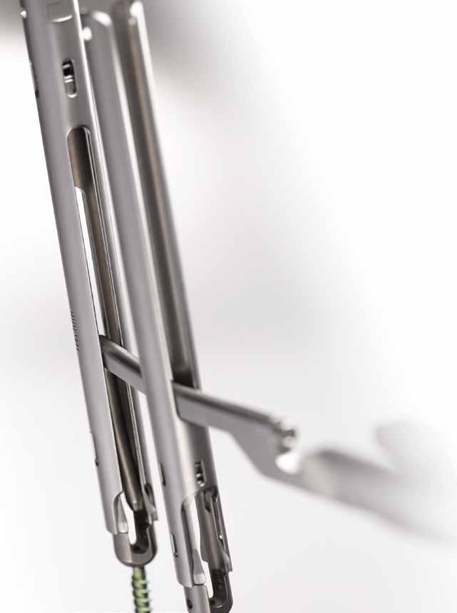
16 Versatility for the Demands of MIS Trauma Stabilization The importance of slot height for spinal trauma Speed & Security of Rod Delivery Through Proximal Extension: V2 Extension Slots allow controlled rod passage through the proximal extension, eliminating the uncertainty of rod insertion through a remote incision Immediate rod capture confirmation provides the surgeon the confidence to quickly advance the V2 Rod through multiple extensions 100mm 20mm V2 Screw Extension Competitor S Screw Extension 14

17 system guide Flexibility to Deliver Any Curvature Rod Optimized Slot Height allows simple passage of kyphotic, lordotic, or dual curve rods Rod Options: V2 Rods come in straight, lordosed and kyphosed configurations from 30mm 600mm 15
18 Tumor

 Treatment Method and Materials: Bilateral transpedicular tumor resection and decompression was performed at L2 through the PIPELINE Expandable")

 and good sagittal and coronal alignment (Figure 4) At three months, patient reports back pain is resolved and has resumed many normal activities For this unfortunate tumor")
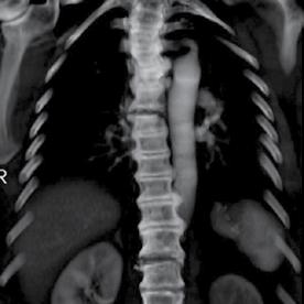
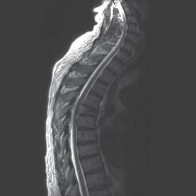
19 Minimally invasive treatment of Spinal Tumors Using the Viper 2 System Ira Goldstein, MD & Robert F. Heary, MD University of Dentistry and Medicine, New Jersey, Department of Neurosurgery Figure 1: CT Scan Figure 2: MRI Scan Figure 3: Lateral CT Scan Figure 4: A-P Radiograph History of Present Illness and Imaging: A 56 year old male with a squamous cell tumor in L2, collapse of the L2 vertebral body and accompanying severe stenosis at the spinal canal (Figure 1) Imaging revealed lesions at the L1, L2, L3, L4 and L5 vertebral bodies (Figure 2) Treatment Method and Materials: Bilateral transpedicular tumor resection and decompression was performed at L2 through the PIPELINE Expandable retractor placed through a 30mm mid-line incision Vertebroplasties were performed at L1, L3, L4 and L5 to support the weaken bone Ten Percutaneous VIPER Screws were placed bi-laterally at T11 - L3 and L4 Two 200mm VIPER 2 rods were percutaneously inserted starting from T11 OR time was approximately 3.5 hours with 200cc of blood loss and no complications Follow-up Results: Patient was ambulating on postoperative day one and was discharged on day three Post-op imaging showed full height restoration at the L2 level (Figure 3) and good sagittal and coronal alignment (Figure 4) At three months, patient reports back pain is resolved and has resumed many normal activities For this unfortunate tumor case, the VIPER 2 System allowed us to fully treat this weakened patient with minimal blood loss. These minimally invasive stabilization techniques are extremely beneficial for ailing patients who may not be able to tolerate a traditional open procedure. TUMOR


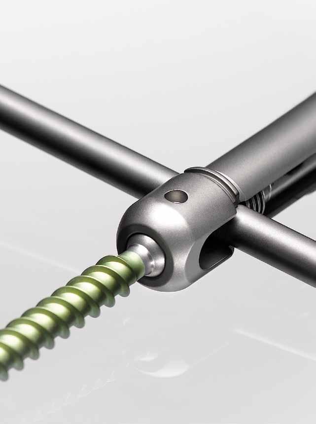
20 Streamlined MIS Posterior Fixation for Tumor Surgery Versatility to Instrument the Entire Thoracolumbar Spine A wide range of rod options for kyphotic & lordotic curves Truly percutaneous rod introduction options optimized for short & long segments Full compatibility with DePuy Spine s EXPEDIUM 5.5 System for hybrid construct options 18


21 system guide Percutaneous Revision Options V2 screw extensions can be quickly re-attached in-situ to revise & extend constructs Elegance of the X-Tab Screw Design 12mm outer diameter minimizes skin incision & muscle trauma Built-in threaded reduction for easy rod approximation Integrated break-off reduction tabs eliminate the need for extension assembly 19
22 Surgical Technique

 Ensure that the C-Arm is positioned correctly for each targeted level by adjusting the")
23 system guide Pedicle Targeting OR Set-Up The patient should be positioned prone lying face down on a radiolucent table It is recommended to use a Jackson Table, to assist in achieving the proper patient positioning and an unrestricted fluoroscopic view. Confirm the C-Arm will allow for easy rotation in the lateral, oblique, and A/P positions around the table Tables that prohibit unobstructed A/P and lateral images should be not be used for this procedure Fluoroscopic Planning Use A/P and lateral fluoroscopy to identify and target the appropriate level(s) Ensure that the C-Arm is positioned correctly for each targeted level by adjusting the position of the C-Arm until both endplates are parallel and the spinous process is equidistant from the center of each pedicle when viewed on A-P fluoroscopy The C-Arm may need to be repositioned for each appropriate level Determine the Skin Incision Location Place a guidewire on the patient perpendicular to the axis of the spine at the targeted level. Using A-P fluoroscopy, position the guidewire such that its projection transects the center of both pedicles in the cephalad-caudal direction. Use a surgical marker to transfer that plane to the patient Place guidewires on the patient parallel to the axis of the spine. Using A-P fluoroscopy, position the guidewire such that its projection aligns to the lateral pedicle wall of the targeted level and the adjacent levels. The lateral pedicle wall of adjacent levels may also be estimated at this time. Use a surgical marker to transfer this plane onto the patient SURGICAL TECHNIQUE The skin incision for each level should be at least 1cm lateral to the intersection of the two lines. This distance may vary depending on size of the patient
. Insert the Jam Shidi Needle through incision and dock the tip on the bony anatomy of the desired level.")
24 Pedicle Targeting Jam Shidi needle placement A longitudinal incision about 1.5cm is made through the skin and fascia. (An incision of 1.5cm will match the diameter of the Screw Extensions used later in the procedure). Insert the Jam Shidi Needle through incision and dock the tip on the bony anatomy of the desired level. Confirm position by using lateral fluoroscopy Using A-P fluoroscopy, advance the Jam Shidi Needle to the pedicle entry point at the intersection of the facet and transverse process. Confirm that the tip of the Jam Shidi Needle is at the center of the lateral border of the pedicle on an A-P image. Gently tap the Jam Shidi Needle to engage the trocar tip into the pedicle Tip: using a surgical marker, draw a line on the Jam Shidi Needle approximately 20mm proximal to the patient s skin. When this mark is flush with the patient s skin, the distal end of the needle should be through the typical pedicle and into the vertebral body Advance the Jam Shidi needle through pedicle using A-P fluoroscopy to direct the tip towards the center of the pedicle. The needle should not advance more than three quarters of the way across pedicle, starting from the lateral edge of the pedicle. Continue advancement until the needle enters the vertebral body. Confirm placement with A/P and lateral fluoroscopy to ensure that the Jam Shidi Needle does not breach the wall of the pedicle Remove the inner stylet of the Jam Shidi Needle 22
 to ensure adequate fixation into the cancellous bone.")
 onto the guidewire 20mm proximal to the Jam Shidi handle and impacting the forceps until the needle driver contacts the Jam Shidi Use caution when placing the")
25 system guide Guidewire Placement Select a guidewire with either a sharp or blunt tip, based on surgeon preference. Insert the guidewire into the Jam Shidi Needle. Advance the guidewire beyond the tip of the Jam Shidi Needle (approximately 20mm) to ensure adequate fixation into the cancellous bone. Confirm placement with A/P and lateral fluoroscopy to ensure that the guidewire does not breech the wall of the pedicle or the vertebral body Tip: To ensure proper depth, drive the guidewire by clamping a needle driver (forceps) onto the guidewire 20mm proximal to the Jam Shidi handle and impacting the forceps until the needle driver contacts the Jam Shidi Use caution when placing the guidewire. Markings on the wire designate 5mm increments and can be used to determine penetration depth. Additionally, the depth markers can be used to monitor unintentional guidewire advancement or rotation Once the guidewire is placed to desired depth, carefully remove the Jam Shidi Needle while holding the guidewire Note: For multi-level constructs it is recommended to place ALL guidewires prior to inserting Pedicle Screws 23


26 Pedicle Preparation Two options are provided for dilating soft tissue in preparation for tapping Option 1: A Combined Dilator/Cannula Insert the 7mm dilator with handle into the Pedicle Preparation Cannula and rotate with downward pressure until the two pieces snap and lock together Advance the combined instrument over the guidewire until the distal tip of the instrument contacts the pedicle. Confirm placement with fluoroscopy. Push down on the outer cannula until it separates from the 7mm dilator and contacts the bone. Remove the dilator while holding the guidewire and the cannula in place Advance the appropriate sized Cannulated Self-Drilling Tap over the guidewire and into the outer cannula. Proceed to the Pedicle Tapping section of this surgical technique NOTE: VIPER 2 taps are undersized to the corresponding screw size by 0.5mm to ensure optimal screw purchase. Hence, a 6mm tap is actually 5.5mm in diameter. Undersizing the tap may result in difficulty starting the screw. The corresponding tap size should be used for the chosen screw diameter. option 2: Tap Sheath Depress the Unlock button on the side of the Tap Sheath and insert the Cannulated Self-Drilling Tap into the top of the sheath. Advance the tap until the horizontal marking on the tap shaft aligns with the top of the sheath then rotate until the vertical markings align with those on the sheath. Depress the lock button to secure the assembly together. The Cannulated Self-Drilling Tap and the Tap Sheath should now be coupled Verify that the tap does not move relative to the sheath while the lock button is engaged Advance Tap Sheath assembly over the guidewire until the distal end of the tap contacts the pedicle. Confirm position with fluoroscopy. Depress the unlock button and proceed to the Pedicle Tapping section of this surgical technique 24

27 system guide Tap Pedicle While controlling the tap sheath or the tap cannula, advance the appropriate size Cannulated Self-Drilling Tap over the guidewire into the pedicle by turning the tap in a clockwise manner. Depth markings on the proximal half of the tap can be used to determine the tap depth and appropriate screw length While tapping, care should be taken to avoid unintentional guidewire advancement or rotation. Do not advance the tap beyond the tip of the guidewire as doing so may result in unintentional wire removal. Use caution not to bend or kink the guidewire while advancing the tap It is recommended that fluoroscopy be used while tapping to monitor the depth of the tap and ensure the guidewire is not unintentionally advanced NOTE: VIPER 2 taps are undersized to the corresponding screw size by 0.5mm to ensure optimal screw purchase. Hence, a 6mm tap is actually 5.5mm in diameter. Undersizing the tap may result in difficulty starting the screw. The corresponding tap size should be used for the chosen screw diameter. 25


28 Screw Loading Choose the appropriate length, diameter, and type of screw. There are two screw types: Cannulated X-tab Screws V2 Closed Extension Cannulated VIPER Screws V2 Open Extension Use the appropriate loading procedure described below for each type of screw CANNULATED POLYAXIAL VIPER SCREWs with extensions Prior to attempting to attach a Screw Extension to a screw, ensure the Castle Nut is fully loosened by turning it counterclockwise with the Castle Nut Tightener Open both hinged doors on the appropriate screw caddy exposing the top of the screw Heads. Ensure that all of the Screws are fully seated in the caddy. Guide the Alignment Block into the grooves located in the top of the caddy until it is fully seated NOTE: The loading block MUST be fully seated in order to function properly 26

29 system guide Insert the Screw Extension into through the Alignment Block Assembly. Press down firmly to engage the Extension with the Screw Head. An audible pop will signal that the Extension is provisionally attached to the TOP NOTCH feature on the Screw Head NOTE: If excessive resistance is encountered, double check the fit of the Alignment Block, ensure that the Castle Nut is fully loosened and verify that the force applied is vertical Alternatively, a small plastic mallet may be used to deliver a quick strike to the top of the extension for loading Remove the Screw Extension and check the provisional attachment by lightly tugging on the screw while holding the Extension and verifying that the screw is aligned with the Extension. Once this has been verified, use the Castle Nut Tightener to fully secure the screw to the Screw Extension. Use caution to avoid over tightening CANNULATED POLYAXIAL EXTENDED TAB (X-Tab) REDUCTION VIPER SCREW LOADING Guide an X-Tab Sleeve over the tabs of the screw until it is fully seated against the Screw Head. This sleeve will help prevent unintentional separation of the tabs from Screw Heads. If resistance is encountered, ensure that the sleeve is properly aligned with the tabs 27

30 Screw Insertion Insert the appropriate Polyaxial Driver into the assembly and thread the instrument into the Screw Head rotating clockwise until it stops. This step should align the Screw Shank with the extended tabs and lock the polyaxial motion of the screw NOTE: An insertion sleeve MUST be placed over the tabs of the screw prior to insertion. This will allow for greater manipulation of the screw and prevent premature detachment of the tabs NOTE: If using an Open Screw Extension, the reinforcement post should be inserted to provide increased stability and to reduce tissue hang-ups Guide the first Screw Extension assembly over a guidewire down to the pedicle and thread the polyaxial screw into the pedicle. The guidewire should be removed as soon as the screw is through the pedicle and enters the vertebral body. While inserting the screw into the pedicle, monitor the markers on the guidewire to avoid unintentional advancement and rotation 28

31 system guide To maintain full polyaxial capability, the Screw Head should not be fully seated against the bone Once the screw is inserted to the desired depth, remove the Polyaxial Driver or X-Tab Polyaxial Driver by turning the handle counterclockwise while firmly holding the Screw Extension or Extended Tab assembly. Verify polyaxial capability by manipulating the Screw Extension The height of each screw must be set appropriately to accommodate the curvature of the rod. Screw height can be verified with lateral fluoro or by checking the alignment of the top of the extensions. For single level constructs, confirm that the Screw Heads are at equal heights. For multi-level constructs, verify that the Screw Heads replicate the curvature of the rod Remove the Reinforcement Posts for the Open Extensions. Repeat Screw placement procedures at each surgical level 29

32 Rod Measuring Insert one arm of the Rod Measuring Caliper into each of the outermost extensions until each leg is fully seated in the Screw Head. Check placement via fluoroscopy. Additionally, placement can be verified by ensuring that the circumferential lines on the shafts of the Rod Measuring Caliper align with the top of each extension Once correctly positioned, read the rod length measurement indicated at the top of the caliper NOTE: The Rod Measuring Caliper can be used to measure segments greater than 140mm by adding two or more measurements together Attach Rod to Appropriate Rod Holder Select the appropriate Rod Holder based on the length of rod that will be inserted - Conventional Rod Holder for rod lengths of 100mm or less - Advanced Rod Holder for rod lengths greater than 100mm Depending on the curvature of the spine at the operated levels, select the pre-lordosed or pre-kyphosed rod that best fits the measured rod length. Alternatively, straight rods can be contoured to the patient s anatomy. Angled and Advanced Rod Holders Rod placement into Rod Holder Notch oriented up towards Rod Holder 30

33 system guide NOTE: The appropriate sagittal plane contour can estimated by placing the rod atop the Screw Extensions or directly on the patient s skin adjacent to the Screw Extensions After choosing the appropriate length rod, contour and corresponding Rod Holder, insert the connection end of the rod into the pocket of the Rod Holder ensuring that the notch on the connection end of the rod is facing up towards the handle of the Rod Holder Connect the Torque Limiting Handle to the X-15 Rod Tightening shaft. Use this instrument to tighten the Rod Locking Bolt of the Rod Holder until the Torque Limiting handle clicks. Verify that the rod is securely attached to the Rod Holder 31
34 Conventional Rod Insertion Use both Closed and Open Extensions in conjunction with the Conventional Rod Holder Align the slots of the Screw Extensions and rotate the Closed Screw Extension so that the arrow points towards the Open Screw Extension. Position the Conventional Rod Holder handle to be parallel to the skin surface with the lead tip of the rod facing downward. Insert the Rod Holder Assembly through the Open Screw Extension(s), and advance the Rod Holder into the slot of the Closed Screw Extension. The entire rod should be contained within the Closed Screw Extension Use the Rod Holder to align the Screw Extensions until they are parallel with one another If the Screw Extensions are crossed, the surgeon should attempt to uncross them. If it is not possible, use the Rod Holder to bypass the Open Screw Extension and guide the rod into the slot of the Closed Screw Extension Advance the distal end of the rod towards the screw, down the Closed Screw Extension until it touches the top of the Screw Head or it is as deep as the tissue will allow. It is necessary for the distal end of the rod to be below the fascia before proceeding 32
.")
, twist the Open Extension about its axis. If the Extension does not rotate, then the rod has been properly passed.")
35 system guide Rotate the Rod Holder Handle Upwards 90º until it nests with the proximal end of the Closed Extension. This action will guide the rod into the distal slot of the Open Screw Extension(s). To confirm the rod is seated inside the Closed Screw Extension, align the vertical and horizontal markers on the Rod Holder with the arrow and vertical line on the Closed Screw Extension NOTE: To verify the rod has passed through the Open Screw Extension(s), twist the Open Extension about its axis. If the Extension does not rotate, then the rod has been properly passed. If the Extension is able to rotate, the rod is not contained within the Extension and rod placement should be re-attempted. FLUOROSCOPY SHOULD BE USED TO VERIFY ADEQUATE ROD OVERHANG AT EACH END OF THE CONSTRUCT 33

. Insert the rod into the cephalad slot of the Extension. The tip of the rod should be contained within the Closed Screw Extension.")
36 Advanced Rod Insertion Use Closed Extensions and/or X-Tab Screws with the Advanced Rod Holder Assemble and insert Closed Extensions or screws over guidewires. Align the openings of the Screw Extensions as much as possible. Rotate the cephalad-most Screw Extensions so the arrow points in the cephalad direction Position the Rod Holder Handle to be as parallel as possible to the skin surface, with the rod parallel to the axis of the slots of the Extension (perpendicular to the skin). Insert the rod into the cephalad slot of the Extension. The tip of the rod should be contained within the Closed Screw Extension. Advance the distal end of the rod straight down towards the screw until it touches the top of the Screw Head or it is as deep as the tissue will allow. It is necessary for the distal end of the Rod to be below the fascia before proceeding Rotate the handle of the Rod Holder toward the cephalad direction approximately 45º. This action will guide the tip of the rod towards each successive Extension NOTE: Depending on the curvature of the spine, the Rod Holder may need to be rotated along an arc that parallels that curvature of the spine 34

37 system guide Continue to advance the rod subfascially into the adjacent Extensions by moving the Rod Holder towards each subsequent Extension in a linear fashion. Verify that the rod has passed through an Extension by attempting to rotate the Extension about its axis. If you are unable to rotate the Extension, the rod has properly passed within the Extension. This process should be conducted as the rod is passed at each level. The rod passage should end inside the most caudal Extension NOTE: To help align multiple Extensions, guide the Screw Extension Alignment guide on the outside of all Extensions by introducing from the caudal direction When necessary, the rod can be directed by manipulating the Extensions while adjusting the rod position and orientation with the Rod Holder. Fluoroscopy can provide additional guidance during rod insertion Engage the distal half of the Advanced Rod Holder into outer slot of the cephalad-most Closed Screw Extension. Fluoroscopy can be used to confirm rod placement and appropriate overhang at the outermost Extensions. Once in final position, the rod should be locked down with Set Screws. The Rod Holder will need to be removed prior to placing a Set Screw at that location 35

38 Set Screw Insertion Load a Set Screw from the caddy onto the X25 Inserter. Twist the proximal knob on the handle until the Set Screw is secured. Do not over tighten the locking feature. Doing so may damage the instrument. Guide the X25 Inserter into any Screw Extension not occupied by the Rod Holder and loosely tighten the Set Screw to capture the rod. The Screw Head should remain mobile to enable repositioning of the Screw Extension, which may assist during subsequent steps If the proximal depth marker on the shaft of the X25 Inserter is the top of the Screw Extension, then the Set Screw is seated within the Screw Head. To verify proper engagement, pull-up slightly on the X25 Inserter to ensure the Set Screw is captured in the Screw Head before disengaging. Remove the X25 Inserter by turning the proximal knob counter-clockwise and withdrawing the instrument NOTE: If difficulty is encountered introducing the Set Screw into the Screw Head, the rod may lie above the Screw Head. Use Fluoroscopy to verify rod placement. If rod approximation is required, utilize the Rod Approximator to deliver the Set Screw using the procedure described in the Rod Approximator section 36


39 system guide Rod Approximation using the VIPER 2 Rod Approximator Attach the cap of the Rod Approximator to the Screw Extension. Align the vertical lines on the cap with the corresponding lines on the proximal end of the Extension. Push the cap of the Rod Approximator onto the Screw Extension until the Approximator snaps into place and the buttons engage the slots. To verify secure attachment, lightly pull on the cap to check attachment to Extension. NOTE: When using the Rod Approximator with the Open Extension, insert the Open Screw Reinforcement Post before use Load a Set Screw on the Self-Retaining Approximating Set Screw Driver by pushing down on a Set Screw until it is fully seated on the flange of the Self-Retaining Set Screw Driver NOTE: Ensure that the tip of the driver is protruding past the Set Screw by approximately 1mm 37


40 Rod approximation using the VIPER 2 Rod Approximator Insert the loaded Self-Retaining Set Screw Driver through the Rod Approximator cap and into the Extension. The Driver tip will contact the Rod Rotate the Rod Approximator handle up to engage flange on the Self-Retaining Approximating Set Screw Driver. Squeeze the Approximator handle to introduce the rod into the Screw Head. Continue to squeeze the handle until the rod is driven into the Screw Head and the instrument reaches the final locked position NOTE: Incremental reduction can be accomplished by utilizing any one of the multiple teeth on the locking rack The amount of approximation can be measured by using the marker bands on the proximal end of the Self-Retaining Set Screw Driver. The distance between each band is 5mm. Proper Rod placement can be verified by ensuring the final marker band is aligned with the top of the Cap of the Pistol Grip. Only after reaching the final locked position should the Set Screw Driver handle be rotated to engage the Set Screw threads To remove the Rod Approximator, depress both buttons on the cap simultaneously and pull-up 38

41 system guide Rod Approximation with the X-Tab Reduction Screws Load a Set Screw from the caddy onto the X25 Inserter. Twist the proximal knob on the handle until the Set Screw is secured. Guide the first Set Screw into the center of the Extended Reduction tab. The Set Screw should engage the reduction thread approximately 7mm above the top of the Screw Head. Rotate the handle of the driver clockwise to engage the reduction threads and drive the rod into the Screw Head NOTE: The X-Tab Screws will provide approximately 7mm of rod reduction. If greater correction is needed, Standard VIPER Screws connected to VIPER 2 Screw Extensions should be used and rod approximation should be accomplished with the Rod Approximator instrument Continue to rotate the Set Screw Driver until the rod is fully seated in the Screw Head. The proximal depth marker on the X25 Inserter should be aligned with the top of the Reduction Tabs when the Set Screw is seated within the Screw Head. Remove the X25 Inserter by rotating the proximal knob counter-clockwise to loosen from the Set Screw 39
42 Compression/Distraction Assemble the Compression/Distraction Adjustable Fulcrum to the sleeve by aligning the slots on the Adjustable Fulcrum with the opposite geometry on the track of the sleeve. Simultaneously depress both buttons on the Adjustable Fulcrum and slide it into the track of the Compression/Distraction Sleeve Final tighten the Set Screw at the end of the construct. It is imperative that the connection features on the ends of the rod are located outside of the Screw Head to ensure that the appropriate screw/rod interface is established. Next, ensure that the Set Screw at the adjacent location is loosely affixed (not tightened) Slide the Compression/Distraction Sleeve over the Extension that has not yet been final tightened. The top of the sleeve will interface with the flats on the Screw Extension or Reinforcement Post. Adjust the Fulcrum so that it is positioned at the top of the Compression/ Distraction Sleeve. Advance the X25 Final Tightener down the Screw Extension that has not been final tightened to engage the Set Screw NOTE: If compressing or distracting with an Open Extension, insert the Open Screw Extension Reinforcement Post. If compressing or distracting with a X-Tab Reduction Screw, insert the X-Tab Sleeve over the tabs to provide an appropriate fit with the Compression/Distraction Sleeve and to prevent premature tab detachment Introduce the Compression Forceps as low as possible below the Fulcrum and compress. Once in the desired position, tighten the Set Screw Distraction may also be applied by moving the Adjustable Fulcrum as low as possible (close as possible to the skin) and advancing the X25 Final Tightener down the Screw Extension to engage the Set Screw. Introduce the Compression Forceps as high as possible above the Fulcrum and compress. Once in the desired position, tighten the Set Screw 40

43 system guide Rod Holder Removal Before removal of the Rod Holder, it should be confirmed fluoroscopically that the proximal end of the rod is fully seated inside the Screw Head with approximately 5mm overhang from each of the Screw Head Insert the X15 Rod Tightener shaft inside the Rod Holder to engage the Rod Holder bolt Turn the X15 Rod Tightener counter-clockwise to disengage the rod from the Rod Holder Remove the X15 Rod Tightener. Rotate the Rod Holder forward slightly while pulling the holder away from the patient to remove 41
 To perform final tightening, place the Counter-Torque/Rod Stabilizer around one of the Extensions.")


44 Final Tightening/Counter-Torque Using fluoroscopy, verify that the rod overhangs the outermost Screws by approximately 5mm. (The rod connection features should be fully outside the Screw head) To perform final tightening, place the Counter-Torque/Rod Stabilizer around one of the Extensions. Ensure that the notches of the stabilizer straddle the Rod. Assemble the X25 Final Tightener to the Final Tightening Torque Handle, pass through the Screw Extension, and engage the Set Screw NOTE: If Final tightening on a X-Tab Screw, ensure that the smaller X-Tab Counter-Torque stabilizer is used Rotate the Torque Wrench Handle clockwise, while applying Counter-Torque via the Counter-Torque/Rod Stabilizer, until the torque handle clicks. Repeat for additional Set Screws For patients with good bone quality, the Counter-Torque wrench can alternatively be used to provide Counter-Torque Slide the Counter-Torque Wrench over the Extension and engage the flats. When used on an Open Extension, the Open Screw Extension reinforcement post should also be used. Follow the final tightening procedure described above 42


45 system guide Screw Extension Removal Assemble the Castle Nut Driver for removal by inserting the Inner Removal Sleeve into the top of the Castle Nut Driver until snaps and locks into place. Insert the Inner Removal Shaft into the Inner Removal Sleeve until the proximal head of the shaft snaps into the first groove of the Inner Removal Sleeve. This is the unlocked position and there should be a gap between the plastic handle and the metal proximal cap Insert the Castle Nut Driver into the Screw Extension until the Driver engages the Castle Nut of the Extension. To verify engagement, the top of the Extension should be aligned with the circumferential marker band on the Castle Nut Driver Assembly Once the Castle Nut is engaged, push down on the head of the Inner Removal Shaft, until it engages the second groove on the Inner Removal Sleeve, this is the Locked position. The Castle Nut Driver and Screw Extension are now linked together NOTE: The marker band is located on the distal end of the Castle Nut Driver when being used to remove a Closed Screw Extension. The marker band is located on the proximal end of the Castle Nut Driver, just distal to the handle, when being used to remove an Open Screw Extension 43

46 Screw Extension Removal Rotate the Castle Nut Driver four (4) full turns. This action will loosen the Extension from the Screw Head. If the Screw Extension does not automatically disconnect from the screw, rotate the Screw Extension 90º and apply slight upward pressure NOTE: The Extension will not require significant force to be removed. If there is difficulty removing the Extension, verify that the Castle Nut Driver is coupled to the Extension then continue to rotate the driver while applying gentle upward force To remove the Extension from the Castle Nut Driver push the lock/unlock button and separate the Extension from the Castle Nut Driver. The Castle Nut Driver should now be in the unlocked position 44

47 system guide X-Tab Removal Insert the Tab Removal tool into the center of the two tabs ensuring that the large cylinder portion is inside the screw tabs (centered over the Screw Head) while the thin tang portion is fully capturing the outside of the tab. Advance the Tab Remover until it reaches the Screw Head and can no longer be advanced Rock the Tab Remover outward (away from the center of the screw) approximately 15º until the tab breaks away from the Screw Head NOTE: This motion may need to be repeated a few times to ensure proper breakage The tab should be retained inside the Tab Remover. Remove the tab by depressing the button at the top of the Tab Remover handle. Ensure that the tab is removed prior to repeating this technique on the next tab 45

48 Product Catalog


49 system guide Instruments ITEM # DESCRIPTION VIPER 2 Pedicle Prep Cannula VIPER 2 Tap Sheath VIPER 2 Awl, Cannulated VIPER 2 Ratcheting Modular Straight Handle, Cannulated VIPER 2 Ratcheting Modular T-Handle, Cannulated Cannulated Tap Dual Lead, 4.35mm Cannulated Tap Single Lead, 4.35mm VIPER 2 5mm Self Drilling Tap, Cannulated and Dual Lead VIPER 2 6mm Self Drilling Tap, Cannulated and Dual Lead VIPER 2 7mm Self Drilling Tap, Cannulated and Dual Lead VIPER 2 8mm Self Drilling Tap, Cannulated and Dual Lead VIPER 2 9mm Self Drilling Tap, Cannulated and Dual Lead Pedicle Prep Cannula, Large Diameter VIPER Ball Tip Feeler Polyaxial Screw Driver Shaft, Cannulated Rod Pusher Guide VIPER 2 X15 Hexlobe Rod Tightener VIPER 2 T20 Hexlobe Driver Shaft VIPER 2 Rod Tightener Handle, Torque Limiting VIPER Screw Extension, Closed VIPER 2 Neuro Stimulation Sleeve VIPER 2 Screw Extension, Open VIPER 2 Open Screw Extension Reinforcement Post VIPER 2 Castle Nut Tightener, Torque Limiting VIPER 2 Castle Nut Tightener, Removal Shaft VIPER 2 Castle Nut Tightener, Removal Sleeve NOTE: VIPER 2 taps are undersized to the corresponding screw size by 0.5mm to ensure optimal screw purchase. Hence, a 6mm tap is actually 5.5mm in diameter. Undersizing the tap may result in difficulty starting the screw. The corresponding tap size should be used for the chosen screw diameter VIPER 2 Rod Gauge VIPER 2 Rod Holder, Angled VIPER 2 Rod Holder, Bolt VIPER 2 Extension Alignment Guide, Open VIPER 2 Rod Holder, Advanced PRODUCT Catalog 47

50 ITEM # DESCRIPTION Rod Holder, Kerrison French Rod Bender VIPER 2 Rod Approximator, Pistol Grip VIPER 2 X25 Approximating Set Screw Inserter, Pistol Grip VIPER 2 X25 Set Screw Inserter, Self-Retaining VIPER 2 Compression Assembly PLIF SG TBar Compressor Intermediate Tightener X VIPER 2 Rod Stabilizer/Anti-Torque Sleeve VIPER 2 Anti-Torque Wrench VIPER 2 Final Tightener Handle, Torque Limiting VIPER 2 Final Tightener Shaft Cases and Trays ITEM # DESCRIPTION VIPER 2 Instrument Case VIPER 2 Instrument Case 1, Tray VIPER 2 Instrument Case 1, Tray VIPER 2 Instrument Case 2, Tray VIPER 2 Instrument Case Lid VIPER 2 Instrument Case 2, Tray VIPER 2 Instrument Case 3, Tray VIPER 2 Instrument Case 3, Tray VIPER 2 Implant Tray VIPER 2 Implant Tray Lid VIPER 2 Rod Caddy VIPER 2 Loading Block VIPER 2 5 /7mm Screw Caddy VIPER 2 6mm Screw Caddy 48
51 system guide Rods VIPER 2 KYPHOSED ROD ITEM # DESCRIPTION VIPER 2 Kyphosed Rod, Ti VIPER 2 Kyphosed Rod, Ti VIPER 2 Kyphosed Rod, Ti VIPER 2 Kyphosed Rod, Ti VIPER 2 Kyphosed Rod, Ti VIPER 2 Kyphosed Rod, Ti VIPER 2 Kyphosed Rod, Ti VIPER 2 Kyphosed Rod, Ti VIPER 2 Kyphosed Rod, Ti VIPER 2 Kyphosed Rod, Ti VIPER 2 Kyphosed Rod, Ti VIPER 2 Kyphosed Rod, Ti VIPER 2 Kyphosed Rod, Ti VIPER 2 LORDOSED ROD ITEM # DESCRIPTION VIPER 2 Lordosed Rod, Ti VIPER 2 Lordosed Rod, Ti VIPER 2 Lordosed Rod, Ti VIPER 2 Lordosed Rod, Ti VIPER 2 Lordosed Rod, Ti VIPER 2 Lordosed Rod, Ti VIPER 2 Lordosed Rod, Ti VIPER 2 Lordosed Rod, Ti VIPER 2 Lordosed Rod, Ti VIPER 2 Lordosed Rod, Ti VIPER 2 Lordosed Rod, Ti VIPER 2 Lordosed Rod, Ti VIPER 2 Lordosed Rod, Ti VIPER 2 Lordosed Rod, Ti VIPER 2 Lordosed Rod, Ti VIPER 2 Lordosed Rod, Ti VIPER 2 Lordosed Rod, Ti VIPER 2 Lordosed Rod, Ti 49
52 VIPER 2 STRAIGHT ROD ITEM # DESCRIPTION VIPER 2 Straight Rod, Ti VIPER 2 Straight Rod, Ti VIPER 2 Straight Rod, Ti VIPER 2 Straight Rod, Ti VIPER 2 Straight Rod, Ti VIPER 2 Straight Rod, Ti VIPER 2 Straight Rod, Ti VIPER 2 Straight Rod, Ti VIPER 2 Straight Rod, Ti VIPER 2 Straight Rod, Ti VIPER 2 Straight Rod, Ti VIPER 2 Straight Rod, Ti VIPER 2 Straight Rod, Ti VIPER 2 Straight Rod, Ti VIPER 2 Straight Rod, Ti Cobalt Chromium Alloy Rods ITEM # DESCRIPTION VIPER 2 Lordosed Rod-120mm, CoCr VIPER 2 Straight Rod-120mm, CoCr VIPER 2 Straight Rod-200mm, CoCr VIPER 2 Straight Rod-300mm, CoCr VIPER 2 Straight Rod-400mm, CoCr VIPER 2 Straight Rod-480mm, CoCr VIPER 2 Straight Rod-600mm, CoCr Screws SINGLE-INNER SET SCREW ITEM # DESCRIPTION Single-Inner Set screw, Ti 50
53 system guide MIS CANNULATED POLYAXIAL ITEM # DESCRIPTION MIS Cannulated Polyaxial Screw, 4.35 X MIS Cannulated Polyaxial Screw, 4.35 X MIS Cannulated Polyaxial Screw, 4.35 X MIS Cannulated Polyaxial Screw, 4.35 X MIS Cannulated Polyaxial Screw, 4.35 X MIS Cannulated Polyaxial Screw, 4.35 X MIS Cannulated Polyaxial Screw 5 X 30mm, Ti MIS Cannulated Polyaxial Screw 5 X 35mm, Ti MIS Cannulated Polyaxial Screw 5 X 40mm, Ti MIS Cannulated Polyaxial Screw 5 X 45mm, Ti MIS Cannulated Polyaxial Screw 5 X 50mm, Ti MIS Cannulated Polyaxial Screw 6 X 30mm, Ti MIS Cannulated Polyaxial Screw 6 X 35mm, Ti MIS Cannulated Polyaxial Screw 6 X 40mm, Ti MIS Cannulated Polyaxial Screw 6 X 45mm, Ti MIS Cannulated Polyaxial Screw 6 X 50mm, Ti MIS Cannulated Polyaxial Screw 6 X 55mm, Ti MIS Cannulated Polyaxial Screw 7 X 30mm, Ti MIS Cannulated Polyaxial Screw 7 X 35mm, Ti MIS Cannulated Polyaxial Screw 7 X 40mm, Ti MIS Cannulated Polyaxial Screw 7 X 45mm, Ti MIS Cannulated Polyaxial Screw 7 X 50mm, Ti MIS Cannulated Polyaxial Screw 7 X 55mm, Ti MIS Cannulated Polyaxial Screw 7.5 X 30mm, Ti MIS Cannulated Polyaxial Screw 7.5 X 35mm, Ti MIS Cannulated Polyaxial Screw 7.5 X 40mm, Ti MIS Cannulated Polyaxial Screw 7.5 X 45mm, Ti MIS Cannulated Polyaxial Screw 7.5 X 50mm, Ti MIS Cannulated Polyaxial Screw 7.5 X 55mm, Ti MIS Cannulated Polyaxial Screw, 8 X MIS Cannulated Polyaxial Screw, 8 X MIS Cannulated Polyaxial Screw, 8 X MIS Cannulated Polyaxial Screw, 8 X MIS Cannulated Polyaxial Screw, 8 X MIS Cannulated Polyaxial Screw, 8 X MIS Cannulated Polyaxial Screw, 9 X MIS Cannulated Polyaxial Screw, 9 X 35 51
54 ITEM # DESCRIPTION MIS Cannulated Polyaxial Screw, 9 X MIS Cannulated Polyaxial Screw, 9 X MIS Cannulated Polyaxial Screw, 9 X MIS Cannulated Polyaxial Screw, 9 X 55 Instruments, Cases and Trays X-Tab ITEM # DESCRIPTION X-Tab Insertion Sleeve X-Tab Anti-torque Polyaxial Driver, 10mm X-Tab Tab Key X-Tab Tab Stabilizer X-Tab Derotation Sleeve X-Tab Tab Breaker X-Tab Neuromonitoring Sleeve X-Tab Implant Tray X-Tab Instrument Tray X-Tab Stabilizer Storage X-Tab Screw Measurement Gauge MIS 2-Level Case VIPER 2 Implant Tray Lid Screws MIS Cannulated X-Tab ITEM # DESCRIPTION MIS Cannulated X-Tab 5 X 30mm, Ti MIS Cannulated X-Tab 5 X 35mm, Ti MIS Cannulated X-Tab 5 X 40mm, Ti MIS Cannulated X-Tab 5 X 45mm, Ti MIS Cannulated X-Tab 5 X 50mm, Ti MIS Cannulated X-Tab 5 X 55mm, Ti MIS Cannulated X-Tab 6 X 30mm, Ti MIS Cannulated X-Tab 6 X 35mm, Ti MIS Cannulated X-Tab 6 X 40mm, Ti 52
55 system guide ITEM # DESCRIPTION MIS Cannulated X-Tab 6 X 45mm, Ti MIS Cannulated X-Tab 6 X 50mm, Ti MIS Cannulated X-Tab 6 X 55mm, Ti MIS Cannulated X-Tab 7 X 30mm, Ti MIS Cannulated X-Tab 7 X 35mm, Ti MIS Cannulated X-Tab 7 X 40mm, Ti MIS Cannulated X-Tab 7 X 45mm, Ti MIS Cannulated X-Tab 7 X 50mm, Ti MIS Cannulated X-Tab 7 X 55mm, Ti MIS Cannulated X-Tab 7.5 X 30mm, Ti MIS Cannulated X-Tab 7.5 X 35mm, Ti MIS Cannulated X-Tab 7.5 X 40mm, Ti MIS Cannulated X-Tab 7.5 X 45mm, Ti MIS Cannulated X-Tab 7.5 X 50mm, Ti MIS Cannulated X-Tab 7.5 X 55mm, Ti 25mm REDUCTION X-TAB Polyaxial SCREWS ITEM # DESCRIPTION X-Tab Derotation Sleeve Modular X-25 Drivers Polyaxial Driver, 25mm Tab Breaker, 25mm RATIO DRIVER MIS 25mm X-Tab Polyaxial, 5mm X 30mm, Ti MIS 25mm X-Tab Polyaxial, 5mm X 35mm, Ti MIS 25mm X-Tab Polyaxial, 5mm X 40mm, Ti MIS 25mm X-Tab Polyaxial, 5mm X 45mm, Ti MIS 25mm X-Tab Polyaxial, 5mm X 50mm, Ti MIS 25mm X-Tab Polyaxial, 5mm X 55mm, Ti MIS 25mm X-Tab Polyaxial, 6mm X 30mm, Ti MIS 25mm X-Tab Polyaxial, 6mm X 35mm, Ti MIS 25mm X-Tab Polyaxial, 6mm X 40mm, Ti MIS 25mm X-Tab Polyaxial, 6mm X 45mm, Ti MIS 25mm X-Tab Polyaxial, 6mm X 50mm, Ti MIS 25mm X-Tab Polyaxial, 6mm X 55mm, Ti MIS 25mm X-Tab Polyaxial, 7mm X 30mm, Ti MIS 25mm X-Tab Polyaxial, 7mm X 35mm, Ti 53
Valencia Pedicle Screw Surgical Technique
 Valencia Pedicle Screw Surgical Technique VALENCIA CIRCUIT TABLE OF CONTENTS Design Rationale Indications for Use Surgical Technique 1. Pedicle Preparation 2. Screw Insertion 3. Rod Placement 4. Locking
Threshold Pedicular Fixation System Surgical Technique
 Threshold Pedicular Fixation System Surgical Technique Table of Contents Patient Preparation and Positioning... 2 Determining Incision Location... 3 Assembling the Cannulated Awl... 4 Guide Wire Placement...
EXCELLA MIS. Spinal System
 EXCELLA MIS Spinal System Excella MIS Spinal System INDICATIONS FOR USE The Innovasis Excella MIS Spinal System is intended for use in the non-cervical area of the spine. WARNING: The safety and effectiveness
EXCELLA ll. Spinal System
 EXCELLA ll Spinal System Excella II Spinal System INDICATIONS FOR USE The Innovasis Excella II Spinal System is intended for use in the non-cervical area of the spine. WARNING: The safety and effectiveness
X-spine Surgical Technique
 X-spine Surgical Technique The X90 Pedicle Screw System Revolutionary Design and Function This document is intended exclusively for experts in the field, particularly physicians, and is not intended for
Surgical Technique Manual
 Surgical Technique Manual Surgeon Designers Richard G. Fessler, MD, PhD Northwestern University, Chicago, IL Robert A. Hart, MD Oregon Health and Science University, Portland, OR Robert Labrom, MD Queensland
TECHNICAL BROCHURE. Capture Facet Fixation System
 TECHNICAL BROCHURE Capture Facet Fixation System Table of Contents Product Overview...2 Instruments...4 Capture Facet Screw Surgical Technique Patient Preparation and Positioning...6 Guide Pin Placement...7
SURGICAL TECHNIQUE. SECURIS Pedicle Screw System for Minimally Invasive Surgery. 2 I SECURIS Pedicle Screw System
 Surgical Technique e Guide SECURIS Pedicle Screw System for Minimally Invasive Surgery Securis Pedicle Screw System has been engineered to provide temporary posterior stabilization of the thoracolumbar
M.I.S. MAKE IT SMART IN ONE SYSTEM. Surgical Technique. Hip Knee Spine Navigation
 M.I.S. MAKE IT SMART IN ONE SYSTEM Surgical Technique Hip Knee Spine Navigation M.U.S.T. Mini Open Surgical Technique Hip Knee Spine Navigation 2 C O N T E N T S 1 INTRODUCTION 4 2 SURGICAL TECHNIQUE 5
Thunderbolt. surgical technique. MIS Pedicle Screw System. Where Nimble and Secure Intersect
 Thunderbolt TM MIS Pedicle Screw System Where Nimble and Secure Intersect surgical technique i www.choicespine.com System Features Dovetail set screw: Minimizes head splay and cross-threading Secure connection
Surgical Technique & Product Catalogue. Guide for Open & MIS Procedures
 Surgical Technique & Product Catalogue Guide for Open & MIS Procedures INTRODUCTION The VIPER Cortical Fix Fenestrated Screw System is the first pedicle screw implant to offer enhanced fixation in both
LUMBAR POSTERIOR MINIMALLY INVASIVE SYSTEM. Surgical Technique
 LUMBAR POSTERIOR MINIMALLY INVASIVE SYSTEM Surgical Technique Joint Spine Sports Med M.U.S.T. Mini Open Surgical Technique Joint Spine Sports Med CAUTION Federal law (USA) restricts this device to sale
Cervical Solutions. Optio-C Anterior Cervical Plate. with Allograft/Autograft. Surgical Technique Guide
 Cervical Solutions Optio-C Anterior Cervical Plate with Allograft/Autograft Surgical Technique Guide 2 Optio-C Anterior Cervical Plate with Allograft/Autograft Surgical Technique Guide The Optio-C System
HydraLok. Operative Technique. Polyaxial Pedicle Screw System
 HydraLok Operative Technique Polyaxial Pedicle Screw System Table of Contents Introduction...1 OPERATIVE TECHNIQUE OVERVIEW...2 DETAILED OPERATIVE TECHNIQUE...4 LOCATE AND PREPARE THE PEDICLE...4 PROBE
EXPEDIUM 5.5 Spine System Family Product Catalogue
 EXPEDIUM 5.5 Spine System Family Product Catalogue Including: EXPEDIUM EXPEDIUM Vertebral Body Derotation Universal Connector Set Cobalt Chromium Rods INTRODUCTION Contents EXPEDIUM Spine System is a comprehensive
Zimmer Small Fragment Universal Locking System. Surgical Technique
 Zimmer Small Fragment Universal Locking System Surgical Technique Zimmer Small Fragment Universal Locking System 1 Zimmer Small Fragment Universal Locking System Surgical Technique Table of Contents Introduction
XRL A modular expandable radiolucent vertebral body replacement system
 XRL A modular expandable radiolucent vertebral body replacement system This publication is not intended for distribution in the USA. SURGICAL TECHNIQUE Table of Contents Introduction XRL 2 AO Spine Principles
L8 Spine System SURGICAL TECHNIQUE. Add: No.1-8, Tianshan Road, Xinbei District, Changzhou, Jiangsu, China
 Add: No.-8, Tianshan Road, Xinbei District, Changzhou, Jiangsu, China 23022 Tel: 0086 59 8595556 Fax: 0086 59 859555 Http://www.kanghui.com Add: F25, Shanghai International Pharmaceutical Trad & Exhibition
Handling instructions. USS Low Profile. Thoracolumbar posterior fixation system.
 Handling instructions USS Low Profile. Thoracolumbar posterior fixation system. U Table of contents Introduction Indications and contraindications 3 USS Low Profile implants 4 Handling implants with stick
EXPEDIUM VERSE Spinal System
 EXPEDIUM VERSE Spinal System SYSTEM GUIDE CONTENTS 1. PRODUCT OVERVIEW 1 FEATURES AND BENEFITS 1 IMPLANT DESIGN 5 INSTRUMENT DESIGN AND SET CONFIGURATION 6 SET CONTENTS 7 2. SURGICAL TECHNIQUE 9 SCREW
operative technique Universal Application
 operative technique Universal Application Introduction Introduction Building upon the design rationale of the Xia Spinal System, the new Xia Spinal System represents the latest advancement in spinal implant
100 Interpace Parkway Parsippany, NJ
 100 Interpace Parkway Parsippany, NJ 07054 www.biometspine.com 800-526-2579 All trademarks are the property of Biomet, Inc. or one of its subsidiaries, unless otherwise indicated. Rx Only. 2009 EBI, LLC.
 Visit our website on www.biotech-medical.com The DLP - Dorso-Lumbar Polyaxial Screw System has been designed to address the pathologies of the thoracolumbar spine. The DLP System contains a wide range
O PE RATIV E TE C HN IQ U E. Minimally Invasive Posterior Fixation
 O PE RATIV E TE C HN IQ U E TM Minimally Invasive Posterior Fixation Table of Contents 1 PRE-OPERATIVE PLANNING Patient Positioning Pedicle Identification and Incision Planning 4 OPERATIVE TECHNIQUE Incision
Ballista Percutaneous Screw Placement System. Surgical Technique
 Ballista Percutaneous Screw Placement System Surgical Technique Contents Introduction... Page 1 Features And Benefits... Page 2 Implants... Page 3 Instruments... Page 4 Surgical Technique... Page 8 Indications
Y o u r Id e a s En g i n e e r e d t o Li f e
 ISSYS LP Spinal Fixation System Surgical Guide Y o u r Id e a s En g i n e e r e d t o Li f e In t r o d u c t i o n ISSYS LP Sp i n a l Fixation System The foundation of the ISSYS LP Spinal Fixation System
USS Variable Axis Screw (VAS) System. For posterior fixation of the lumbar spine.
 System. For posterior fixation of the lumbar spine.") USS Variable Axis Screw (VAS) System. For posterior fixation of the lumbar spine. Technique Guide Instruments and implants approved by the AO Foundation Table of Contents Introduction USS Variable Axis
USS Variable Axis Screw (VAS) System. For posterior fixation of the lumbar spine. Technique Guide Instruments and implants approved by the AO Foundation Table of Contents Introduction USS Variable Axis
Surgical Technique FOR U.S. DOMESTIC USE ONLY
 Surgical Technique FOR U.S. DOMESTIC USE ONLY Polyaxial Screws HA Coated Polyaxial Screws Uniplanar Screws Reduction Screws Reduction Uniplanar Screws Modular Screws TABLE OF CONTENTS Reform Pedicle Screw
BAK/C Cervical Anterior Interbody Fusion System
 Surgical Technique BAK/C Cervical Anterior Interbody Fusion System The Comfortable Choice for Cervical Fusion BAK/C Cervical Surgical Technique 1 The BAK/C Cervical Fusion System is an alternative to conventional
TiLock XT Minimally Invasive Surgery (MIS) Pedicle Screw System
 Pedicle Screw System") Minimally Invasive Surgery (MIS) Pedicle Screw System Surgical Technique Guide 2 Minimally Invasive Surgery (MIS) Pedicle Screw System The Genesys Spine Minimally Invasive Surgery (MIS) Pedicle Screw System
Minimally Invasive Surgery (MIS) Pedicle Screw System Surgical Technique Guide 2 Minimally Invasive Surgery (MIS) Pedicle Screw System The Genesys Spine Minimally Invasive Surgery (MIS) Pedicle Screw System
TiLock XT Minimally Invasive Surgery (MIS) Pedicle Screw System
 Pedicle Screw System") TiLock XT Minimally Invasive Surgery (MIS) Pedicle Screw System The Genesys Spine TiLock XT Minimally Invasive Surgery (MIS) Pedicle Screw System consists of rods (straight and curved), lock screws, and
TiLock XT Minimally Invasive Surgery (MIS) Pedicle Screw System The Genesys Spine TiLock XT Minimally Invasive Surgery (MIS) Pedicle Screw System consists of rods (straight and curved), lock screws, and
Ballista Percutaneous Screw Placement System
 Surgical Technique Ballista Percutaneous Screw Placement System A Minimally Invasive Approach for Posterior Spinal Surgery True percutaneous system Helical Flange locking mechanism Contents Introduction...
Imola Lateral IBF System Surgical Technique
 Imola Lateral IBF System Surgical Technique IMOLA CIRCUIT TABLE OF CONTENTS Design Rationale Instructions for Use Surgical Technique 1. Table Mounting 2. Surgical Planning & Targeting 3. Access and Preparation
TSLP Thoracolumbar Spine Locking Plate
 Anterior thoracolumbar spine locking plate TSLP Thoracolumbar Spine Locking Plate Surgical Technique Image intensifier control This description alone does not provide sufficient background for direct use
VECTRA-T SURGICAL TECHNIQUE. The Translational Anterior Cervical Palate System. This publication is not intended for distribution in the USA.
 VECTRA-T The Translational Anterior Cervical Palate System This publication is not intended for distribution in the USA. SURGICAL TECHNIQUE Image intensifier control This description alone does not provide
VERTEX SELECT. surgical technique. adjustability. Flexibility. adaptability. Reconstruction System
 VERTEX SELECT Reconstruction System surgical technique adjustability. Flexibility. adaptability. adjustability. Flexibility. adaptability. The VERTEX SELECT Reconstruction System is a comprehensive set
Ref: Q400-09T1 EBI Spine. September 05/VS02. c/o BIOMET Spain Orthopaedics, S.L.
 Ref: Q400-09T1 EBI Spine. September 05/VS02 c/o BIOMET Spain Orthopaedics, S.L. www.ebimedical.com EBI Omega 21 TM LP Since its introduction in 1996, and with thousands of patients treated so far, the
Technique Guide. 3.5 mm LCP Low Bend Medial Distal Tibia Plate Aiming Instruments. Part of the 3.5 mm LCP Percutaneous Instrument System.
 Technique Guide 3.5 mm LCP Low Bend Medial Distal Tibia Plate Aiming Instruments. Part of the 3.5 mm LCP Percutaneous Instrument System. Table of Contents Introduction 3.5 mm LCP Low Bend Medial Distal
VIPER PRIME TM System. Surgical Technique
 VIPER PRIME TM System Surgical Technique Contents Product Overview Introduction 2 Features and Benefits 3 One Tool Screw Insertion 5 Surgical Technique OR Set Up 6 Assembly of the VIPER PRIME TM Inserter
Conventus CAGE PH Surgical Techniques
 Conventus CAGE PH Surgical Techniques Conventus Orthopaedics The Conventus CAGE PH (PH Cage) is a permanent implant comprised of an expandable scaffold, made from nitinol and titanium, which is deployed
MATRIX Spine System Deformity
 A Solution for Simple and Complex Spine Pathology MATRIX Spine System Deformity Surgical Technique Image intensifier control This description alone does not provide sufficient background for direct use
Dymaxeon Spine System. Simple, Streamlined, Smart. Surgical Procedure
 Simple, Streamlined, Smart Surgical Procedure Introduction The Dymaxeon pedicle screw system offers the spinal surgeon an outstanding system for stabilization of spinal deformity, reduction of spondylolisthesis,
Thoracolumbar Spine Locking Plate (TSLP) System. A low-profile plating system for anterior stabilization of the thoracic and lumbar spine.
 System. A low-profile plating system for anterior stabilization of the thoracic and lumbar spine.") Thoracolumbar Spine Locking Plate (TSLP) System. A low-profile plating system for anterior stabilization of the thoracic and lumbar spine. Technique Guide Instruments and implants approved by the AO Foundation
Thoracolumbar Spine Locking Plate (TSLP) System. A low-profile plating system for anterior stabilization of the thoracic and lumbar spine. Technique Guide Instruments and implants approved by the AO Foundation
Surgical Technique. CONQUEST FN Femoral Neck Fracture System
 Surgical Technique CONQUEST FN Femoral Neck Fracture System Table of Contents Introduction... 3 Indications... 3 Product Overview... 4 Surgical Technique... 5 Patient Positioning... 5 Reduce the Fracture...
Technique Guide. MATRIX Spine System MIS Instrumentation. The total solution for simple and complex spine pathology.
 Technique Guide MATRIX Spine System MIS Instrumentation. The total solution for simple and complex spine pathology. Table of Contents Introduction MATRIX Spine System MIS Instrumentation 2 AO Principles
TOTAL KNEE ARTHROPLASTY SYSTEM
 SURGICAL TECHNIQUE TOTAL KNEE ARTHROPLASTY SYSTEM 90-SRK-700000 B.0 0 Contents 1. Implant Sizing 2. Surgical Technique a. Incision and Exposure b. Distal Femoral Resection c. Tibial Resection d. Femoral
Replacement Device A modular expandable radiolucent vertebral body replacement system
 XRL Vertebral Body Replacement Device A modular expandable radiolucent vertebral body replacement system SURGICAL TECHNIQUE TABLE OF CONTENTS Introduction XRL System 2 AO Principles 5 Indications and Contraindications
Surgical Technique Guide
 Sacroiliac Joint Fusion System Surgical Technique Guide Moving Life Forward Table of Contents SiCure Implant Overview...2 SiCure System Information...3 X-ray Basics...4 Patient Positioning....5 Surgical
USS Variable Axis Screw
 USS Variable Axis Screw Polyaxial side-opening pedicle screw Surgical technique Original Instruments and Implants of the Association for the Study of Internal Fixation AO/ASIF USS Variable Axis Screw
Royal Oak Cervical Plate System
 Royal Oak Cervical Plate System Manufactured by Nexxt Spine, Inc. Royal Oak Cervical Plate System INTRODUCTION FEATURES AND BENEFITS Table of Contents SURGICAL TECHNIQUE Step 1. Patient Positioning Step
Surgical Technique. Targeter Systems Overview
 Surgical Technique Targeter Systems Overview PERI-LOC Locked Plating System Targeter Systems Overview Table of contents Product overview... 2 Introduction... 2 Indications... 2 Design features and benefits...
PRODUCT SUMMARY Cobalt Chrome Tulip Multiple Options Triple Lead Thread
 PRODUCT SUMMARY Cobalt Chrome Tulip Multiple Options Triple Lead Thread Screws Low Profile 2.72 Footprint x 2.5 Height Square Threaded Locking Cap Geometry reduces risk of cross threading Hexalobular Drive
ONE SYSTEM, MULTIPLE OPTIONS. Surgical Technique. Hip Knee Spine Navigation
 ONE SYSTEM, MULTIPLE OPTIONS Surgical Technique Hip Knee Spine Navigation MUST MINI Surgical Technique Hip Knee Spine Navigation INTRODUCTION The M.U.S.T. Mini posterior cervical screw system is a modular
4.5 System. Surgical Technique. This publication is not intended for distribution in the USA.
 4.5 System Surgical Technique This publication is not intended for distribution in the USA. Contents EXPEDIUM 4.5 Spine System 2 Features and Benefits 3 Surgical Technique Extended Tandem Connector 4 Placement
SURGICAL TECHNIQUE. Standard Reduction HA Coated Modular. Discover the Difference
 SURGICAL TECHNIQUE Standard Reduction HA Coated Modular Discover the Difference TABLE OF CONTENTS REFORM PEDICLE SCREW SYSTEM OVERVIEW 3 TRAY IMAGES & CONTENT 14 SURGICAL TECHNIQUE 34 1. Preoperative Planning
Surgical Technique. Occipito-Cervico-Thoracic System
 OASYS Surgical Technique Occipito-Cervico-Thoracic System System Overview The OASYS Occipito-Cervico-Thoracic System was developed to provide the surgeon with versatility for the treatment of pathologies
Technique Guide. T-PAL. Transforaminal posterior atraumatic lumbar spacer system.
 Technique Guide T-PAL. Transforaminal posterior atraumatic lumbar spacer system. Table of Contents Introduction T-PAL 2 AO Principles 4 Indications and Contraindications 5 Surgical Technique Preparation
Table of Contents.
 surgical technique The Ambassador TM Anterior Cervical Plate System is a versatile system of implants and instruments with a variety of sizes to provide optimal anatomic compatibility. The integrated cam
VIPER PRIME TM System. Surgical Technique
 VIPER PRIME TM System Surgical Technique Contents Product Overview Introduction 2 Features and Benefits 3 One Tool Screw Insertion 5 Surgical Technique OR Set Up 6 Assembly of the VIPER PRIME TM Inserter
L-VARLOCK. Posterior Lumbar Cage with adjustable lordosis. S urgical T echnique
 L-VARLOCK Posterior Lumbar Cage with adjustable lordosis S urgical T echnique Introduction Designed and manufactured by KISCO International, L-VARLOCK cages are made of titanium alloy Ti 6AI 4V (standards
CSS Combined Spine System
 CSS Combined Spine System H- CSS Combined Spine System H- CSS Combined Spinal System : 800000 H-3 CSS Combined Spinal System : 800000 Ref.Number Description Pieces Ref.Number Description Pieces 00000 Open
nvt Transforaminal Lumbar Interbody Fusion System
 nvt Transforaminal Lumbar Interbody Fusion System 1 IMPORTANT INFORMATION FOR PHYSICIANS, SURGEONS, AND/OR STAFF The nv a, nv p, and nv t are an intervertebral body fusion device used in the lumbar spine
mild Devices Kit - Instructions for Use
 INDICATION FOR USE The Vertos mild Devices are specialized surgical instruments intended to be used to perform lumbar decompressive procedures for the treatment of various spinal conditions. CONTENTS AND
Surgical technique. synex. The vertebral body replacement with ratchet mechanism.
 Surgical technique synex. The vertebral body replacement with ratchet mechanism. Table of contents Indications and contraindications 2 Implants 3 Surgical technique 4 Cleaning of instruments 10 Optional
SURGICAL TECHNIQUE GUIDE TRESTLE. Anterior Cervical Plating System
 SURGICAL TECHNIQUE GUIDE TRESTLE Anterior Cervical Plating System 2 SURGICAL TECHNIQUE GUIDE SURGICAL TECHNIQUE GUIDE System Features Large window enables visualization of graft site and end plates Screw
LCP Medial Distal Tibia Plate, without Tab. The Low Profile Anatomic Fixation System with Angular Stability and Optimal Screw Orientation.
 LCP Medial Distal Tibia Plate, without Tab. The Low Profile Anatomic Fixation System with Angular Stability and Optimal Screw Orientation. Technique Guide LCP Small Fragment System Table of Contents Introduction
Biomet Large Cannulated Screw System
 Biomet Large Cannulated Screw System s u r g i c a l t e c h n i q u e A Complete System for Simplified Fracture Fixation 6.5mm & 7.3mm The Titanium, Self-drilling, Self-tapping Large Cannulated Screw
A Fusion of Versatility, Performance and Ease.
 MATRIX Spine System. Degenerative and Deformity. System Guide A Fusion of Versatility, Performance and Ease. Instruments and implants approved by the AO Foundation The MATRIX Spine System is a universal
Surgical Technique 1
 1 Surgical Technique TELLURIDE 2 MIS SPINAL FIXATION SYSTEM The Telluride 2 MIS Spinal Fixation System is a simple, robust and versatile minimally invasive pedicle screw system consisting of implants and
Surgical Technique. DePuy International Ltd St Anthony s Road Leeds LS11 8DT England Tel: +44 (113) Fax: +44 (113)
 Fax: +44 (113)") Surgical Technique DePuy Spine is a joint venture with Biedermann Motech GmbH. This publication is not intended for distribution in the USA. DePuy Spine, Slim-loc and Cam-loc are all trademarks of DePuy
Surgical Technique DePuy Spine is a joint venture with Biedermann Motech GmbH. This publication is not intended for distribution in the USA. DePuy Spine, Slim-loc and Cam-loc are all trademarks of DePuy
Veyron -C Anterior Cervical System Surgical Technique
 Veyron -C Anterior Cervical System Surgical Technique 2 Veyron-C Anterior Cervical System Surgical Technique Veyron-C Anterior Cervical System Surgical Technique Description, Indications & Contraindications...3
nvp Posterior Lumbar Interbody Fusion System
 nvp Posterior Lumbar Interbody Fusion System 1 IMPORTANT INFORMATION FOR PHYSICIANS, SURGEONS, AND/OR STAFF The nv a, nv p, and nv t are an intervertebral body fusion device used in the lumbar spine following
Technique Guide. Universal Spinal System (USS). Designed to achieve the goals of scoliosis surgery.
. Designed to achieve the goals of scoliosis surgery.") Technique Guide Universal Spinal System (USS). Designed to achieve the goals of scoliosis surgery. Table of Contents Introduction Universal Spinal System 2 AO ASIF Principles of Internal Fixation 3 Indications
Technique Guide Universal Spinal System (USS). Designed to achieve the goals of scoliosis surgery. Table of Contents Introduction Universal Spinal System 2 AO ASIF Principles of Internal Fixation 3 Indications
TiLock 2 Spinal System. Surgical Technique
 TiLock 2 Spinal System Surgical Technique Table of Contents Page Preoperative Planning 4 Pedicle Preparation 5 Probe 5 Tap Pedicle 6 Screw Options 7 Screw Insertion 8 Aligning the Windows 9 Rod Insertion
VIPER Cortical Fix Fenestrated Screw System. Surgical Technique for OPEN & MIS Procedures
 VIPER Cortical Fix Fenestrated Screw System Surgical Technique for OPEN & MIS Procedures Image intensifier control This description alone does not provide sufficient background for direct use of DePuy
USS II ILIO-SACRAL Modular System for Stable Fixation in the Sacrum and Illium
 USS II ILIO-SACRAL Modular System for Stable Fixation in the Sacrum and Illium Instruments and implants approved by the AO Foundation. This publication is not intended for distribution in the USA. TECHNIQUE
VLIFT System Overview. Vertebral Body Replacement System
 VLIFT System Overview Vertebral Body Replacement System VLIFT System System Description The VLIFT Vertebral Body Replacement System consists of a Distractible In Situ (DIS) implant, which enables the surgeon
AccuVision Minimally Invasive Spinal Exposure System
 Surgical Technique AccuVision Minimally Invasive Spinal Exposure System Working Beyond the Tube Lighted blades for superior viewing Maximum stabilization Contents Introduction... Page 1 Features and Benefits...
Solitaire Anterior Spinal System
 Surgical Technique Solitaire Anterior Spinal System Independent Stabilization for the Anterior Column Available in Titanium and Contents Introduction... Page 1 Design Features... Page 2 Instruments...
Surgical Technique. Forearm Fracture Solutions
 Surgical Technique Forearm Fracture Solutions Acumed is a global leader of innovative orthopaedic and medical solutions. We are dedicated to developing products, service methods, and approaches that improve
Technique Guide. NFlex. Semi-rigid rods for posterior lumbar stabilization.
 Technique Guide NFlex. Semi-rigid rods for posterior lumbar stabilization. Table of Contents Introduction NFlex 2 Indications and Contraindications 4 NFlex Principles 6 Surgical Technique Preoperative
Introduction. Our hope is that this Surgical Technique Guide enhances your knowledge and contributes to clinical success for your patients.
 Surgical Technique Introduction DePuy Spine continues to support the goal of expanding the spine surgeon s options for the treatment of spinal disorders. Collaborating with renowned spine specialists,
In-Space. Interspinous distraction through a mini-open, posterior, unilateral approach.
 In-Space. Interspinous distraction through a mini-open, posterior, unilateral approach. Surgical Technique Posterior Approach PRODUCT OBSOLETED 30th September 2017 DSEM/SPN/0915/0348(1) This publication
POLYAXIAL SPINE SYSTEM D E G E N E R A T I V E
 S U R G I C A L T E C H N I Q U E En POLYAXIAL SPINE SYSTEM D E G E N E R A T I V E LOW PROFILE POLYAXIAL SPINE SYSTEM A01110050 Straight spatula A01110060 Curved spatula A01110070 Bone probe A01114500
SYNEX The vertebral body replacement with ratchet mechanism
 SYNEX The vertebral body replacement with ratchet mechanism Instruments and implants approved by the AO Foundation. This publication is not intended for distribution in the USA. SURGICAL TECHNIQUE Image
3. PATIENT POSITIONING & FRACTURE REDUCTION 3 8. DISTAL GUIDED LOCKING FOR PROXIMAL NAIL PROXIMAL LOCKING FOR LONG NAIL 13
 Contents IMPLANT FEATURES 2 1. INDICATIONS 3 2. PRE-OPERATIVE PLANNING 3 3. PATIENT POSITIONING & FRACTURE REDUCTION 3 4. INCISION 4 5. ENTRY POINT 4-6 6. PROXIMAL NAIL INSERTION 6-7 7. PROXIMAL LOCKING
Surgical Technique International Version
 Surgical Technique International Version PERI-LOC PFP 4.5mm Proximal Femur Locking Plate Surgical Technique Table of contents Product overview...2 Introduction...2 Indications...3 Case examples...4 Design
Module: #15 Lumbar Spine Fusion. Author(s): Jenni Buckley, PhD. Date Created: March 27 th, Last Updated:
: Jenni Buckley, PhD. Date Created: March 27 th, Last Updated:") Module: #15 Lumbar Spine Fusion Author(s): Jenni Buckley, PhD Date Created: March 27 th, 2011 Last Updated: Summary: Students will perform a single level lumbar spine fusion to treat lumbar spinal stenosis.
Module: #15 Lumbar Spine Fusion Author(s): Jenni Buckley, PhD Date Created: March 27 th, 2011 Last Updated: Summary: Students will perform a single level lumbar spine fusion to treat lumbar spinal stenosis.
SFX Cross Connector System. Surgical Technique Guide
 SFX Cross Connector System Surgical Technique Guide Introduction The EXPEDIUM SFX Cross Connector System redefines ease-of-use, implant versatility, and construct security with an advanced top-loading
3.5 MM VA-LCP PROXIMAL TIBIA PLATE SYSTEM
 3.5 MM VA-LCP PROXIMAL TIBIA PLATE SYSTEM Part of the DePuy Synthes Variable Angle Periarticular Plating System SURGICAL TECHNIQUE TABLE OF CONTENTS INTRODUCTION 3.5 mm VA-LCP Proximal Tibial Plate 2 AO
Mandible External Fixator II. Provides treatment for fractures of the maxillofacial area.
 Mandible External Fixator II. Provides treatment for fractures of the maxillofacial area. Technique Guide This publication is not intended for distribution in the USA. Instruments and implants approved
NewBridge. Laminoplasty Fixation INTERNATIONAL EDITION
 NewBridge L A M I N O P L A S T Y F I X A T I O N S Y S T E M Laminoplasty Fixation INTERNATIONAL EDITION Table of Contents 1 INTRODUCTION 2 PRE-OPERATIVE 3 OPERATIVE 10 INSTRUCTIONS FOR USE 12 PART NUMBERS
VTI INTERLINK PEDICLE SCREW SYSTEM
 VTI INTERLINK PEDICLE SCREW SYSTEM SURGICAL TECHNIQUE FORWARD THINKING FOR THE BACK. DEVICE DESCRIPTION The VTI InterLink Pedicle Screw System is comprised of polyaxial pedicle screws in various diameters
O PE RATIV E TE C HN IQ U E. ProView. Expandable Retractor System U.S. EDITION
 O PE RATIV E TE C HN IQ U E ProView M I N I M A L A C C E S S P O R TA L ( M A P ) S Y S T E M Expandable Retractor System U.S. EDITION Table of Contents 1 INTRODUCTION 2 OPERATIVE TECHNIQUE 9 PART NUMBERS
FACET WEDGE. Facet joint fixation device.
 FACET WEDGE. Facet joint fixation device. Technique Guide Synthes FACET WEDGE Technique Guide /44 Synthes FACET WEDGE Technique Guide /44 Table of Contents Introduction FACET WEDGE 3 AO Principles 4 Indications
Patella Planing System
 REFERENCE GUIDE AND SURGICAL TECHNIQUE Patella Planing System SPECIALIST INSTRUMENTS AN ONLAY PATELLA PREPARATION SYSTEM TECHNIQUE FOR PRIMARY PATELLAR RESURFACING The Specialist 2 Patellar Planer System
The Most Reliable Spinal Solution
 MFG : 09.02.20 REV : 1 4CIS VANE introduces you the reliable pedicle screw The Most Reliable Spinal Solution Non-slip threaded joint Ergonomic design Wedged trapezoid thread Superior locking mechanism
Zimmer Natural Nail System
 Zimmer Natural Nail System Antegrade Femoral Nail Surgical Technique (Piriformis Fossa & Greater Trochanteric Approaches) Zimmer Natural Nail System Antegrade Femoral Surgical Technique 1 Zimmer Natural
Knee Surgical Technique
 Knee Surgical Technique COMPASS Universal Hinge by Jimmy Tucker, M.D. Orthopaedic Surgeon Director, Arkansas Sports Medicine, P.A. Little Rock, Arkansas Table of contents Design features 3 Indications
Surgical Technique. Anterolateral and Medial Distal Tibia Locking Plates
 Surgical Technique Anterolateral and Medial Distal Tibia Locking Plates PERI-LOC Periarticular Locked Plating System Anterolateral and Medial Distal Tibia Locking Plates Surgical Technique Contents Product