Thoracolumbar Solutions. Aspen. MIS Fusion System. Surgical Technique Guide
|
|
|
- Kory Short
- 6 years ago
- Views:
Transcription


1 Thoracolumbar Solutions Aspen MIS Fusion System Surgical Technique Guide


2 2 Aspen MIS Fusion System Surgical Technique Guide Designed to help optimize surgical results when implanting the Aspen MIS Fusion System
3 Aspen MIS Fusion System Surgical Technique Guide 3 TABLE OF CONTENTS System Overview 4 Surgical Exposure 5 Site Preparation 6 Inserting the Aspen Implant 11 Bone Grafting and Closure 17 Removing the Aspen Implant 18 Instruments 19 Implants 20 Important Information on the Aspen MIS Fusion System 21 The following general Surgical Technique Guide is for illustrative purposes only. As with all surgical procedures, the technique used in each case will depend on the surgeon s medical judgment as to the best treatment for each patient. Only those individuals with specialized training and experience in spine surgery should attempt to use the Aspen MIS Fusion System. Detailed preoperative clinical and diagnostic evaluation followed by carefully executed surgical technique is essential. Zimmer Biomet Spine does not practice medicine. Each physician should exercise his or her own independent judgment in the diagnosis and treatment of an individual patient, and this information does not purport to replace the comprehensive training physicians have received. Refer to the package insert for a complete list of prescribing information, including indications, contraindications, warnings, precautions, potential adverse effects, and patient counseling information. This technique guide was developed in conjunction with health care professionals.


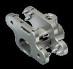
4 4 Aspen MIS Fusion System Surgical Technique Guide SYSTEM OVERVIEW The Aspen MIS Fusion System provides robust posterior fixation in the non-cervical spine. It is a less invasive fixation solution to facilitate interbody and posterior fusions. Standard Medium Flared 5-1 Post Plate Assembled Plates Set Screw Lock Plate

5 Aspen MIS Fusion System Surgical Technique Guide 5 SURGICAL EXPOSURE Note: Interbody fusion technique is not covered in this technique guide. If performing an interbody fusion, disc preparation and interbody spacer placement are typically performed prior to placement of the Aspen device. Figure 1 STEP 1 Position the patient in the prone position on the operating table (Figure 1). Note: The type of frame used depends on the intended procedure, but as a rule of thumb, select the same type of patient positioning that would be chosen if pedicle screws were to be used instead. Avoid hyperlordosing the operative segment. STEP 3 Make a midline incision about 3cm 5cm in length to expose the spinous processes at the operative level. STEP 4 Elevate the paraspinal musculature and other soft tissue to expose the spinous processes and lamina to the medial border of the facet joints. STEP 2 Identify the spinous processes at the level to be instrumented using manual palpation and intraoperative imaging.
6 6 Aspen MIS Fusion System Surgical Technique Guide SITE PREPARATION STEP 5 Clear the fusion site of connective and soft tissues, lightly decorticating the bone surfaces. A burr, rongeur or rasp may be used to remove the interspinous ligament. The interspinous ligament and supraspinous ligament may optionally be incised or dilated without complete removal. Depending on the surgeon s preferred technique, the supraspinous ligament (SSL) may be left intact, reflected or removed entirely. Possible reasons for leaving the SSL intact include: a. Using the intact SSL as a natural inhibitor to prevent over-distraction and guide proper implant sizing. b. Desire to preserve as much of the natural anatomy as possible. Possible reasons for removing the SSL include: a. Increased visualization to facilitate a decompression. b. Simplified device implantation. c. Ability to pack bone graft material posterior to the device for a supplemental fusion mass.
. Caution: Do not remove excessive amounts of bone, particularly from the base of the spinous processes and midline lamina.")
7 Aspen MIS Fusion System Surgical Technique Guide 7 Figure 2 STEP 6 If a direct decompression is desired, perform a conservative laminotomy, partial facetectomy, foraminotomy or other decompression procedure as needed (Figure 2). Caution: Do not remove excessive amounts of bone, particularly from the base of the spinous processes and midline lamina. Weakening the posterior arch by aggressive bone removal may increase the risk of intraoperative or postoperative fracture of the adjoining spinous processes or posterior arch. Decorticate the desired bone surfaces, preparing the fusion sites for bone graft. STEP 7 If the facets are hypertrophied and do not allow for proper anterior placement of the implant, the facets may be trimmed. Choosing the Aspen Medium implant, which features a 3mm shorter barrel than the standard Aspen implant, may help avoid the facets. Caution: Do not perform a complete facetectomy. Preserving a sufficient portion of the facets is required to provide biomechanical stability for axial rotation and transverse shear loads.
 and puncture the interspinous ligament, placing it as far anterior as possible (Figure 3).")

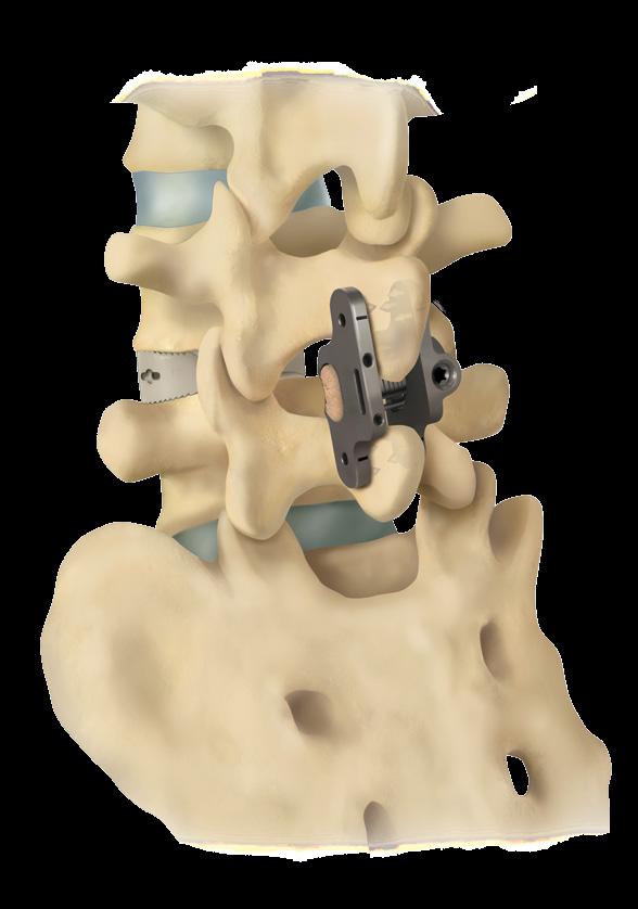
8 8 Aspen MIS Fusion System Surgical Technique Guide SITE PREPARATION (continued) Figure 3 Figure 4 STEP 8 If the interspinous ligament has been left intact, insert the initial dilator (attaches to the quick connect handle [gray]) and puncture the interspinous ligament, placing it as far anterior as possible (Figure 3). Note: Anterior placement reduces stress on the spinous processes and allows fixation to the thicker, stronger bone at the spinous process/lamina junction. Posterior placement may increase the risk of spinous process fracture. STEP 9 With the initial dilator in place, confirm that the operative level is correct and placement is appropriate (e.g., anterior placement). Note: In the lumbar spine, the barrel of the Aspen device should be roughly in line with the pedicle of the inferior level. For example, for an L4 L5 fusion, the barrel of the Aspen device should be roughly in line with the pedicle of L5 (Figure 4).


 while dilating the space (Figure 6a).")
9 Aspen MIS Fusion System Surgical Technique Guide 9 Figure 6a Figure 5 Figure 6b STEP 10 Using the spreader, measure the interspinous separation distance. This measurement will be used to select the appropriate rasp and implant size (Figure 5). Caution: Do not over-dilate the implant space. Excessive force may fracture the spinous processes. To ensure optimal tactile feedback during distraction, keep the spreader s ratchet up (disengaged) while dilating the space (Figure 6a). Once the desired tension is achieved, drop the ratchet down to determine the corresponding rasp and implant size (Figure 6b).

: Attach the gray handle to the desired rasp size.")

.")


10 10 Aspen MIS Fusion System Surgical Technique Guide SITE PREPARATION (continued) Figure 8 Figure 7 Figure 9 Figure 10 STEP 11 If using the rasps and insertion guide sleeves to facilitate post plate insertion (e.g., if the SSL is left intact): Attach the gray handle to the desired rasp size. For initial rasping, it is recommended to use a rasp one size smaller than measured with the spreader. After inserting the rasp into the interspinous space, rotate the instrument cephalad and caudad to decorticate the spinous processes and prepare the fusion site (Figure 7). If necessary, repeat the decortication process with a larger size rasp. Remove the rasp from the interspinous space and slide the corresponding sleeve over the rasp (Figure 8). Insert the rasp/sleeve assembly into the interspinous space (Figure 9). Note: Use caution when inserting both the rasp and sleeve at this stage to ensure that lateral forces being applied to the spinous processes do not cause a fracture. Keeping the sleeve in the interspinous space, remove the rasp to create a cannula for the post plate side of the implant (Figure 10).


. Plate flare: The Aspen Flared 5-1* implants feature a 45 flare on one end of the implant assembly.")
11 Aspen MIS Fusion System Surgical Technique Guide 11 INSERTING THE ASPEN IMPLANT Figure 11 Figure 12 STEP 12 Choose the appropriate size and shape of Aspen implant to best fit the anatomy. Barrel diameter: The appropriate barrel diameter should be based on the fit of the previously used rasps and/or spreader. Note: Over-sizing the barrel may cause excessive stress on the spinous processes. Barrel length: A standard Aspen barrel (21mm long) or Aspen Medium* barrel (18mm long) may be chosen. Anatomical factors such as spinous process width and size/location of the facet may influence selection. For example, a standard Aspen barrel may be best suited for a thick spinous process while an Aspen Medium may be preferred for a hypertrophic facet (Figure 11). Plate flare: The Aspen Flared 5-1* implants feature a 45 flare on one end of the implant assembly. This flare may provide an enhanced fit at L5 S1 (where the S1 spinous process is often smaller and more angled than others) or for any level where a more anterior placement is desired (e.g., at the base of the spinous processes, closer to the lamina junction) (Figure 12). * Special Order
.")
.")
12 12 Aspen MIS Fusion System Surgical Technique Guide INSERTING THE ASPEN IMPLANT (continued) Figure 13 Figure 14 STEP 13 Attach the post plate implant to the post plate inserter. The small pins on the inserter tip engage the holes in the top aspect of the post plate (Figure 13). Once the tips are positioned, the adjuster knob must be fully tightened to secure the implant to the inserter. When the adjuster knob is fully tightened, no threads should be visible between the handles (Figure 14). STEP 14 If desired, pack bone graft material inside the barrel prior to or after post plate implantation.
.")


13 Aspen MIS Fusion System Surgical Technique Guide 13 Figure 15 Figure 16 STEP 15 Three techniques are available for placement of the barrel of the post plate into the interspinous space. Preferred Technique 1 From the opposite side of the sleeve s handle, introduce the implant barrel into the sleeve s cannula (Figure 15). Rotate the implant into its final position while simultaneously removing the sleeve from the interspinous space (Figure 16). Optional Technique 2 If the sleeve is not being used, begin inserting the post plate of the implant rotated approximately 45 to 90 in the sagittal plane. In this orientation, the open edge of the barrel can be guided into the space. Rotate the implant back into final position while simultaneously pushing the barrel into the interspinous space. Optional Technique 3 If the supraspinous ligament has been reflected or removed and the interspinous ligament excised, the implant may be inserted from the direct-midline approach, rather than from a paramedian approach. Note: The more dorsally positioned end of the plate may be oriented either cephalad or caudad (corresponding to the post plate situated on the patient s left or right, respectively). Cephalad orientation often allows the Z-shape of the plates to better contour to the slant of the laminae.

.")
14 14 Aspen MIS Fusion System Surgical Technique Guide INSERTING THE ASPEN IMPLANT (continued) Figure 17 Figure 18 STEP 16 Choose the lock plate that corresponds to the post plate size. Prior to attaching the inserter, ensure that the set screw has been backed up, flush with the top of the lock plate, to allow the plate to slide unobstructed onto the barrel. Note: To expedite the surgery, back up the set screw in each of the set s lock plates at the start of the procedure. Attach the lock plate to the lock plate inserter. The peg side of the inserter fits inside the set screw while the curved portion surrounds the set screw housing (Figure 17). STEP 17 Slide the lock plate over the barrel until it comes in contact with the spinous processes (Figure 18).


15 Aspen MIS Fusion System Surgical Technique Guide Good anterior placement Poor anterior placement Figure 19 Figure 20 STEP 18 Before compressing the plates and tightening the set screw, ensure that the device is placed as far anteriorly as possible, and that the plate does not protrude above the lumbodorsal fascia. Confirm correct placement with radiograph (Figure 19). Note: Avoid implant placement too far posterior, as this may increase the risk of spinous process fracture. The lock plate will angulate up to ±10 in the coronal plane to accommodate different spinous process widths (Figure 20). STEP 19 Using the laser-marked lines just above the implant s divots for reference, insert the conical tips of the compressors into the lateral divots in each plate. Once the compressors are engaged with the plates, the lock plate inserter and post plate inserter may be removed.
. Squeeze both compressors simultaneously or alternate back and forth. Compress until the spikes are fully seated into the bone.")
16 16 Aspen MIS Fusion System Surgical Technique Guide INSERTING THE ASPEN IMPLANT (continued) 2 1 Figure 21 Figure 22 STEP 20 Using the compressors, clamp the plates against the spinous processes, driving the spikes into the bone (Figure 21). Squeeze both compressors simultaneously or alternate back and forth. Compress until the spikes are fully seated into the bone. Note: Take care not to over-compress and risk crushing or weakening the cortex, thereby increasing the risk of spinous process fracture (i.e., maximum compression force does not necessarily equate to better fixation). Visually confirm that the spikes are fully seated into the bone, with good apposition of the plates against the sides of the spinous processes. STEP 21 Attach the set screw driver shaft to the 30in-lb (3.4Nm) torque limiting handle (black) (Figure 22). Place the set screw driver into the set screw. Ensure that the driver tip is fully seated into the set screw to prevent rounding of the set screw s hexalobe drive features. While keeping the compressors engaged with the plates to serve as a counter-torque, tighten the set screw until the torque handle clicks twice (Figure 23). Note: To ensure that the set screw fully engages the post plate, visually confirm that the barrel protrudes beyond the lateral edge of the lock plate s set screw housing.

17 Aspen MIS Fusion System Surgical Technique Guide 17 BONE GRAFTING AND CLOSURE Figure 23 Figure 24 STEP 22 Remove the compressors. Manually and visually inspect the implant assembly to confirm secure fixation. Confirm proper placement of the implant using fluoroscopy. STEP 23 If fusing through the facets, decorticate articular surfaces and place bone graft in the usual manner. If desired, additional posterior bone grafting material may be placed across the lamina, around the implant and/or in the posterolateral gutter. If not already done, bone graft material may be packed inside the barrel prior to placement of the implant (Figure 24). If the supraspinous ligament was resected, bone graft material may be packed posterior to the device between the tips of the spinous processes. If the supraspinous ligament was reflected, it may be sutured back to the tips of the spinous process. The fascia may be closed back to the supraspinous ligament. After the construct is implanted and bone graft completed, close the surgical site using standard techniques.
18 18 Aspen MIS Fusion System Surgical Technique Guide REMOVING THE ASPEN IMPLANT 1. If a nonunion develops, or if the components loosen or break, the device should be revised and/or removed immediately before serious injury occurs. Failure to immobilize a delayed nonunion of bone will result in excessive and repeated stresses on the implant and anatomy. By the mechanism of fatigue, these stresses can cause eventual loosening or breakage of the device or fracture of the underlying bone. 2. Use the set screw driver (provided in the standard Aspen surgical instrument set) to loosen the locking set screw. Although the Aspen-specific set screw driver is recommended, a T10 Torx driver may be used as a substitute. 3. The plates can then be separated with a Cobb elevator or similar instrument and removed from the spinous processes. Explanted surgical implants must never be reused.
 PART NUMBER Post Plate Inserter PART NUMBER 6200-1108 6200-2005 Initial Dilator")
 PART NUMBER 620 0-1115 Rasp SIZE PART NUMBER SIZE PART NUMBER 8")
 PART NUMBER 620 0-110 4 Insertion Guide Sleeve SIZE PART")

19 Aspen MIS Fusion System Surgical Technique Guide 19 INSTRUMENTS Quick Connect Handle, Gray (2) PART NUMBER Post Plate Inserter PART NUMBER Initial Dilator PART NUMBER Lock Plate Inserter PART NUMBER Spreader PART NUMBER Compressor (2) PART NUMBER Rasp SIZE PART NUMBER SIZE PART NUMBER 8 mm mm mm mm mm mm Set Screw Driver Shaft (2) PART NUMBER Insertion Guide Sleeve SIZE PART NUMBER SIZE PART NUMBER 8 mm mm mm mm mm mm Torque Limiting Handle 30in-lb, 3.4Nm, Black (2) PART NUMBER


20 20 Aspen MIS Fusion System Surgical Technique Guide IMPLANTS Aspen Standard SIZE LOCK PLATE POST PLATE SET SCREW 8mm mm mm mm mm mm Aspen Medium SIZE LOCK PLATE POST PLATE SET SCREW 6mm mm mm mm mm Aspen Flared 5-1 SIZE LOCK PLATE POST PLATE SET SCREW 8mm mm mm mm mm mm
21 Aspen MIS Fusion System Surgical Technique Guide 21 IMPORTANT INFORMATION ON THE ASPEN MIS FUSION SYSTEM Device Description The Aspen MIS Fusion System is a posterior attachment spinal fixation system composed of spinous process plates, dedicated surgical instruments and sterilization cases. The components are used to build a construct to provide stabilization of spinal segments in the thoracic, lumbar and sacral spine to support fusion. The Aspen device is part of the Zimmer Biomet Spinal Fixation System, which offers the surgeon a variety of implant components from which to assemble a suitable construct according to each individual patient s needs and requirements. It is essential to use Zimmer Biomet implants with their specifically designed instruments. After a solid fusion occurs, the system serves no functional purpose and should be removed. Removal is indicated because the implants are not intended to transfer or support forces developed during normal activities. However, any decision to remove the device must be made by the physician and the patient, taking into consideration the patient s general medical condition and the potential risk to the patient of a second surgical procedure. Indications for Use The Aspen MIS Fusion System is intended to be used to help provide immobilization and stabilization of spinal segments as an adjunct to fusion of the thoracic, lumbar and/or sacral spine. The system is intended for use with autograft or allograft. The Zimmer Biomet Spinal Fixation System is intended for posterior, non-cervical (T1 S2/ilium) pedicle and non-pedicle spinal fixation, to provide immobilization and stabilization of spinal segments in skeletally mature patients as an adjunct to fusion in the treatment of the following instabilities or deformities: degenerative disc disease (DDD, defined as back pain of discogenic origin with degeneration of the disc confirmed by history and radiographic studies), spondylolisthesis, trauma (i.e., fracture or dislocation); spinal stenosis, deformities or curvatures (i.e., scoliosis, kyphosis and/or lordosis), tumor, pseudarthrosis and failed previous fusion. The Aspen device is a posterior, non-pedicle supplemental fixation device, intended for use at a single level in the non-cervical spine (T1 S1). It is intended for plate fixation/ attachment to spinous processes for the purpose of achieving supplemental fusion in the following conditions: DDD, spondylolisthesis, trauma (i.e., fracture or dislocation) and/or tumor. The Aspen device is intended for use with bone graft material and not intended for stand-alone use. Contraindications Contraindications may be relative or absolute. The choice of a particular device must be carefully weighed against the patient s overall evaluation. Circumstances listed below may reduce the chance of a successful outcome. Contraindications include, but are not limited to: An allergy to titanium or cobalt chrome alloys, or foreign body sensitivity. Where material sensitivity is suspected, appropriate tests must be performed prior to implantation. Known or suspected infection/immune system incompetence, including acute or chronic infectious diseases of any etiology or localization. Any abnormality present which affects the normal process of bone remodeling including, but not limited to, severe osteoporosis involving the spine, bone absorption, osteopenia, active infection at the site or certain metabolic disorders affecting osteogenesis. Morbid obesity. An overweight or obese patient can produce loads on the spinal system, capable of leading to failure of the fixation of the device or failure of the device itself. Any neuromuscular deficit which places an unusually heavy load on the device during the healing period. Open wounds. Pregnancy. Any other medical or surgical condition which would preclude the potential benefit of spinal surgery, such as the presence of congenital abnormalities, elevation of sedimentation rate unexplained by other diseases, elevation of the white blood cell (WBC) count or a marked left shift in the WBC differential count. Any case requiring the mixing of components from other manufacturers systems. Any case requiring the mixture of stainless steel with titanium, or stainless steel with cobalt chrome implant components. Fever or leukocytosis. Signs of local infection or inflammation. Previous history of infection. Alcoholism or heavy smoking. Senility, mental illness or substance abuse, of a severity that the patient may ignore certain necessary limitations and precautions in the use of the implant, leading to failure or other complications.
22 22 Aspen MIS Fusion System Surgical Technique Guide IMPORTANT INFORMATION ON THE ASPEN MIS FUSION SYSTEM (continued) Any patient unwilling to follow postoperative instructions. Inadequate tissue coverage over the operative site. The Aspen device is also contraindicated for incompetent or missing posterior arch (e.g., laminectomy, pars defect, severe osteoporosis). Warnings The safety and effectiveness of pedicle screw spinal systems have been established only for spinal conditions with significant mechanical instability or deformity requiring fusion with instrumentation. These conditions are significant mechanical instability or deformity of the thoracic, lumbar and sacral spine secondary to severe spondylolisthesis (grades 3 and 4) of the L5 S1 vertebra, degenerative spondylolisthesis with objective evidence of neurological impairment, fracture, dislocation, scoliosis, kyphosis, spinal tumor and failed previous fusion (pseudarthrosis). The safety and effectiveness of these devices for any other conditions are unknown. A successful result is not always achieved in every surgical case. This fact is especially true in spinal surgery, where many extenuating circumstances may compromise the results. Precautions The Aspen implants are for single use only. Never reuse any implant, even if it appears unmarked or undamaged. Reuse of the implant components may result in reduced mechanical performance, malfunction or failure of the device. Any implant implanted and then removed must be discarded. Use only new implants for each case. The implantation of spinal fixation systems must only be performed by experienced spinal surgeons with specific training in the use of this system due to the technically demanding procedure presenting a risk of serious injury to the patient. Based on the fatigue testing results, the physician/ surgeon must consider the levels of implantation, patient weight, patient activity level, other patient conditions, etc., which may impact the performance of the system. Preoperatively: The surgeon must be fully conversant with all aspects of the surgical technique and know the indications and contraindications of this type of implant. The surgeon must have acquainted himself before the operation with the specific technique for insertion of the product, which is available from the manufacturer. As part of the preoperative examination, the surgeon must check that no biological, biomechanical or other factors will affect the correct conduct of the operation and the postoperative period. An appropriate range of implant sizes must be available at the time of the operation. Intraoperatively: The correct selection of the type and size of implant appropriate to the patient and the positioning of the implant are extremely important. Postoperatively: Patients must be informed of the precautions to be taken in their everyday life to guarantee a maximum implant service life. It is recommended that regular postoperative follow-up is undertaken to detect early signs of failure of the implants and to consider the action to be taken. Deterioration of the device after bone consolidation cannot be considered to constitute a dysfunction or deterioration in the characteristics of the implants. The implant can be removed after bony healing. The Aspen device has not been evaluated for safety and compatibility in the magnetic resonance (MR) environment. The Aspen device has not been tested for heating or migration in the MR environment.
23
24 Disclaimer: This document is intended exclusively for physicians and is not intended for laypersons. Information on the products and procedures contained in this document is of a general nature and does not represent and does not constitute medical advice or recommendations. Because this information does not purport to constitute any diagnostic or therapeutic statement with regard to any individual medical case, each patient must be examined and advised individually, and this document does not replace the need for such examination and/or advice in whole or in part. Caution: Federal (USA) law restricts this device to sale by or on the order of a physician. Rx Only. Please refer to the package inserts for important product information, including, but not limited to, indications, contraindications, warnings, precautions, adverse effects, and patient counseling information. Manufactured by: Zimmer Biomet Spine, Inc Westmoor Dr. Westminster, CO USA Zimmer GmbH Sulzerallee 8 CH-8404 Winterthur Switzerland zimmerbiomet.com 2016 Zimmer Biomet Spine, Inc. All rights reserved. All content herein is protected by copyright, trademarks and other intellectual property rights, as applicable, owned by or licensed to Zimmer Biomet Spine, Inc. or its affiliates unless otherwise indicated, and must not be redistributed, duplicated or disclosed, in whole or in part, without the express written consent of Zimmer Biomet Spine. This material is intended for health care professionals, the Zimmer Biomet Spine sales force and authorized representatives. Distribution to any other recipient is prohibited US-en-REV1116
A U X I L I A R Y C O N N E C T O R S Surgical Technique
 A U X I L I A R Y C O N N E C T O R S Surgical Technique AUXILIARY CONNECTORS ISSYS LP Auxiliary Connectors The ISSYS LP auxiliary connectors were designed to provide medial-lateral variability for the
Thoracolumbar Solutions. Alpine XC. Adjustable Fusion System. Surgical Technique Guide
 Thoracolumbar Solutions Alpine XC Adjustable Fusion System Surgical Technique Guide 2 Alpine XC Adjustable Fusion System Surgical Technique Guide Designed to help optimize surgical results when using spinous
Y o u r Id e a s En g i n e e r e d t o Li f e
 ISSYS LP Spinal Fixation System Surgical Guide Y o u r Id e a s En g i n e e r e d t o Li f e In t r o d u c t i o n ISSYS LP Sp i n a l Fixation System The foundation of the ISSYS LP Spinal Fixation System
TM TM Surgical Technique
 TM TM Surgical Technique TABLE OF CONTENTS Reli SP Spinous Plating System Overview Device Description Implant Features Indications Instruments Access Instruments Preparation Instruments Insertion Instruments
EXACTECH SPINE. Operative Technique. Cervical Spacer System. Surgeon focused. Patient driven. TM
 EXACTECH SPINE Operative Technique Cervical Spacer System Surgeon focused. Patient driven. TM ACAPELLA ONE Acapella One Cervical Spacer System is an anterior cervical discectomy and fusion device with
UniLink Interspinous Fusion System UniLink 5/1 Interspinous Fusion System UniLink Graft. Surgical Technique
 UniLink Interspinous Fusion System UniLink 5/1 Interspinous Fusion System UniLink Graft Surgical Technique 2 UniLink and UniLink 5/1 Interspinous Fusion System Surgical Technique UniLink and Unlink 5/1
nva Anterior Lumbar Interbody Fusion System
 nva Anterior Lumbar Interbody Fusion System 1 IMPORTANT INFORMATION FOR PHYSICIANS, SURGEONS, AND/OR STAFF The nv a, nv p, and nv t are an intervertebral body fusion device used in the lumbar spine following
Cervical Solutions. Alta. ACDF System. Surgical Technique Guide
 Cervical Solutions Alta ACDF System Surgical Technique Guide 2 Alta ACDF System Surgical Technique Guide A comprehensive system to address a continuum of fixation requirements and anatomic demands. Alta
nvt Transforaminal Lumbar Interbody Fusion System
 nvt Transforaminal Lumbar Interbody Fusion System 1 IMPORTANT INFORMATION FOR PHYSICIANS, SURGEONS, AND/OR STAFF The nv a, nv p, and nv t are an intervertebral body fusion device used in the lumbar spine
ACP. Anterior Cervical Plate System SURGICAL TECHNIQUE
 ACP Anterior Cervical Plate System SURGICAL TECHNIQUE ACP TABLE OF CONTENTS INTRODUCTION 4 INDICATIONS AND CONTRAINDICATIONS 5 WARNINGS AND PRECAUTIONS 6 IMPLANT DESCRIPTION 7 INSTRUMENTS 10 SURGICAL
ACP1 CERVICAL PLATE SPINAL SYSTEM SURGICAL TECHNIQUE GUIDE II.
 I. ACP1 CERVICAL PLATE II. SPINAL SYSTEM SURGICAL TECHNIQUE GUIDE I. Introduction The Gold Standard Orthopaedics, LLC ACP1 Spinal System was designed with surgeons to incorporate strength, functionality,
nvp Posterior Lumbar Interbody Fusion System
 nvp Posterior Lumbar Interbody Fusion System 1 IMPORTANT INFORMATION FOR PHYSICIANS, SURGEONS, AND/OR STAFF The nv a, nv p, and nv t are an intervertebral body fusion device used in the lumbar spine following
Biomechanics of Interspinous Process Fixation and Lateral Modular Plate Fixation to Support Lateral Lumbar Interbody Fusion (LLIF)
") Biomechanics of Interspinous Process Fixation and Lateral Modular Plate Fixation to Support Lateral Lumbar Interbody Fusion (LLIF) Calusa Ambulatory Spine Conference 2016 Jason Inzana, PhD 1 ; Anup Gandhi,
Biomechanics of Interspinous Process Fixation and Lateral Modular Plate Fixation to Support Lateral Lumbar Interbody Fusion (LLIF) Calusa Ambulatory Spine Conference 2016 Jason Inzana, PhD 1 ; Anup Gandhi,
Table of Contents.
 surgical technique The Ambassador TM Anterior Cervical Plate System is a versatile system of implants and instruments with a variety of sizes to provide optimal anatomic compatibility. The integrated cam
Royal Oak Cervical Plate System
 Royal Oak Cervical Plate System Manufactured by Nexxt Spine, Inc. Royal Oak Cervical Plate System INTRODUCTION FEATURES AND BENEFITS Table of Contents SURGICAL TECHNIQUE Step 1. Patient Positioning Step
VTI INTERLINK PEDICLE SCREW SYSTEM
 VTI INTERLINK PEDICLE SCREW SYSTEM SURGICAL TECHNIQUE FORWARD THINKING FOR THE BACK. DEVICE DESCRIPTION The VTI InterLink Pedicle Screw System is comprised of polyaxial pedicle screws in various diameters
Hinged Laminoplasty System surgical technique
 BlackbirdTM Hls Hinged Laminoplasty System surgical technique Blackbird TM Hls The ChoiceSpine Blackbird Hinged Laminoplasty System (HLS) design eliminates fitting plates through trial and error bending.
 Visit our website on www.biotech-medical.com The DLP - Dorso-Lumbar Polyaxial Screw System has been designed to address the pathologies of the thoracolumbar spine. The DLP System contains a wide range
Zimmer Anterior Buttress Plate System. Surgical Technique
 Zimmer Anterior Buttress Plate System Surgical Technique 2 Zimmer Anterior Buttress Plate System Surgical Technique Zimmer Anterior Buttress Plate System Surgical Technique Description, Indications & Contraindications...
Royal Oak IBFD System Surgical Technique Posterior Lumbar Interbody Fusion (PLIF)
") Royal Oak IBFD System Surgical Technique Posterior Lumbar Interbody Fusion (PLIF) Preoperative Planning Preoperative planning is necessary for the correct selection of lumbar interbody fusion devices.
Royal Oak IBFD System Surgical Technique Posterior Lumbar Interbody Fusion (PLIF) Preoperative Planning Preoperative planning is necessary for the correct selection of lumbar interbody fusion devices.
SURGICAL TECHNIQUE GUIDE TRESTLE. Anterior Cervical Plating System
 SURGICAL TECHNIQUE GUIDE TRESTLE Anterior Cervical Plating System 2 SURGICAL TECHNIQUE GUIDE SURGICAL TECHNIQUE GUIDE System Features Large window enables visualization of graft site and end plates Screw
Thoracolumbar Spine Locking Plate (TSLP) System. A low-profile plating system for anterior stabilization of the thoracic and lumbar spine.
 System. A low-profile plating system for anterior stabilization of the thoracic and lumbar spine.") Thoracolumbar Spine Locking Plate (TSLP) System. A low-profile plating system for anterior stabilization of the thoracic and lumbar spine. Technique Guide Instruments and implants approved by the AO Foundation
Thoracolumbar Spine Locking Plate (TSLP) System. A low-profile plating system for anterior stabilization of the thoracic and lumbar spine. Technique Guide Instruments and implants approved by the AO Foundation
Thunderbolt. surgical technique. MIS Pedicle Screw System. Where Nimble and Secure Intersect
 Thunderbolt TM MIS Pedicle Screw System Where Nimble and Secure Intersect surgical technique i www.choicespine.com System Features Dovetail set screw: Minimizes head splay and cross-threading Secure connection
Alamo T Transforaminal Lumbar Interbody System Surgical Technique
 Transforaminal Lumbar Interbody System Surgical Technique Table of Contents Indications and Device Description.............. 1 Alamo T Implant Features and Instruments...........2 Surgical Technique......................
OPERATIVE TECHNIQUE. anterior cervical plating system
 OPERATIVE TECHNIQUE 3º anterior cervical plating system Introduction 1 Pre-Operative Technique 2 Oerative Technique 3 Instructions for Use 12 Part Numbers 16 The surgical technique shown is for illustrative
C-THRU Anterior Spinal System
 C-THRU Anterior Spinal System Surgical Technique Manufactured From Contents Introduction... Page 1 Design Features... Page 2 Instruments... Page 3 Surgical Technique... Page 4 Product Information... Page
Apache Cervical Interbody Fusion Device. Surgical Technique. Page of 13. LC-005 Rev F
 LC-005 Rev F Apache Cervical Interbody Fusion Device Page of 13 Surgical Technique INDICATIONS: When used as an intervertebral body fusion device, the Genesys Spine Interbody Fusion System is indicated
UniWallis TM Posterior Dynamic Stabilization System
 UniWallis TM Posterior Dynamic Stabilization System Surgical Technique Solutions by the people of Zimmer Spine. zimmerspine.eu Table of Contents Indications/Contraindications 2 UniWallis Instruments 3
I. II. SPINAL SYSTEM SURGICAL TECHNIQUE GUIDE
 I. GS1 II. SPINAL SYSTEM SURGICAL TECHNIQUE GUIDE Introduction The Gold Standard Orthopaedics, LLC GS1 Spinal System designed in conjunction with Richard Holt, M.D. incorporates both strength and function
Cervical Spacer System surgical technique
 Blackhawk TM Cervical Spacer System surgical technique Blackhawk TM The BLACKHAWK Cervical Spacer System is designed to provide biomechanical stabilization as an adjunct to fusion. Spinal fixation should
Alamo C. Cervical Interbody System Surgical Technique. An Alliance Partners Company
 Cervical Interbody System Surgical Technique Table of Contents Indications for Use................................1 Device Description............................... 1 Alamo C Instruments..............................
INTELLIGENT SPINAL SYSTEM
 INTELLIGENT SPINAL SYSTEM I. Introduction II. Product Specification III. Surgical Technique IV. Ordering Information V. IFU for Lospa IS SPINAL SYSTEM The LOSPA IS spinal system consists of
OPERATIVE TECHNIQUE. CONSTRUX Mini PTC. Mini PTC Spacer System
 OPERATIVE TECHNIQUE CONSTRUX Mini PTC Mini PTC Spacer System TABLE OF CONTENTS Introduction 1 Operative Technique 2 Part Numbers 6 Indications For Use 7 INTRODUCTION 1 INTRODUCTION The CONSTRUX Mini PTC
HydraLok. Operative Technique. Polyaxial Pedicle Screw System
 HydraLok Operative Technique Polyaxial Pedicle Screw System Table of Contents Introduction...1 OPERATIVE TECHNIQUE OVERVIEW...2 DETAILED OPERATIVE TECHNIQUE...4 LOCATE AND PREPARE THE PEDICLE...4 PROBE
Thoracolumbar Solutions. Zyston Curve. Interbody Spacer System. Surgical Technique Guide
 Thoracolumbar Solutions Zyston Curve Interbody Spacer System Surgical Technique Guide 2 Zyston Curve Interbody Spacer System Surgical Technique Guide The Zyston Curve Interbody System is designed to optimize
TABLE OF CONTENTS. ShurFit Anterior Cervical Interbody Fusion (ACIF) System Overview 2. Implant Specifications 3. Instrument Features 4
 System Overview 2. Implant Specifications 3. Instrument Features 4") Surgical Technique TABLE OF CONTENTS ShurFit Anterior Cervical Interbody Fusion (ACIF) System Overview 2 Product Highlights 2 Indications 2 Implant Specifications 3 Instrument Features 4 Surgical Technique
Surgical Technique TABLE OF CONTENTS ShurFit Anterior Cervical Interbody Fusion (ACIF) System Overview 2 Product Highlights 2 Indications 2 Implant Specifications 3 Instrument Features 4 Surgical Technique
X-spine Surgical Technique
 X-spine Surgical Technique The X90 Pedicle Screw System Revolutionary Design and Function This document is intended exclusively for experts in the field, particularly physicians, and is not intended for
HawkeyeTM Peek. surgical technique
 HawkeyeTM Peek surgical technique Introduction The ChoiceSpine HAWKEYE Vertebral Body Replacement (VBR) System is intended for use in the thoracolumbar spine (T1 - L5) to replace a collapsed, damaged,
Surgical Technique. Apache Anterior Lumbar Interbody Fusion
 Surgical Technique Apache Anterior Lumbar Interbody Fusion 2 Table of Contents Page Preoperative Planning 4 Patient Positioning 4 Disc and Endplate Preparation 4 Distraction/Size Selection 5 Implantation
Ref: Q400-09T1 EBI Spine. September 05/VS02. c/o BIOMET Spain Orthopaedics, S.L.
 Ref: Q400-09T1 EBI Spine. September 05/VS02 c/o BIOMET Spain Orthopaedics, S.L. www.ebimedical.com EBI Omega 21 TM LP Since its introduction in 1996, and with thousands of patients treated so far, the
JuggerLoc Bone-to-Bone System for Ankle Syndesmosis Fixation. Surgical Technique
 JuggerLoc Bone-to-Bone System for Ankle Syndesmosis Fixation Surgical Technique Table of Contents Position and Preparation... 2 Incision... 2 Fracture Reduction... 2 Drill Fibula and Tibia... 3 JuggerLoc
The AperFix II System
 The AperFix II System A Complete Anatomic Solution Transtibial Surgical Technique 2 AperFix II System Transtibial Surgical Technique Figure 1 A Complete Anatomic Solution The Cayenne Medical AperFix and
4.5 System. Surgical Technique. This publication is not intended for distribution in the USA.
 4.5 System Surgical Technique This publication is not intended for distribution in the USA. Contents EXPEDIUM 4.5 Spine System 2 Features and Benefits 3 Surgical Technique Extended Tandem Connector 4 Placement
EXCELLA ll. Spinal System
 EXCELLA ll Spinal System Excella II Spinal System INDICATIONS FOR USE The Innovasis Excella II Spinal System is intended for use in the non-cervical area of the spine. WARNING: The safety and effectiveness
Cervical Solutions. Trinnect. Hydrated Anterior Cervical Spacer System. Surgical Technique Guide
 Cervical Solutions Trinnect Hydrated Anterior Cervical Spacer System Surgical Technique Guide 2 Trinnect Hydrated Anterior Cervical Spacer System Surgical Technique Guide Trinnect Cervical Allograft Spacers
InFix. Anterior Lumbar Device. Surgical Technique Guide
 InFix Anterior Lumbar Device Surgical Technique Guide 2 InFix Anterior Lumbar Device Surgical Technique Guide InFix Anterior Lumbar System s modular design is intended to restore lordosis, disc height
Solitaire Anterior Spinal System
 Surgical Technique Solitaire Anterior Spinal System Independent Stabilization for the Anterior Column Available in Titanium and Contents Introduction... Page 1 Design Features... Page 2 Instruments...
CROSS -FUSE P E E K V B R / I B F SYST E M
 S U R G I C A L T E C H N I Q U E CROSS -FUSE P E E K V B R / I B F SYST E M S U R G I C A L S Y S T E M O V E R V I E W 2 CROSS-FUSE P E E K V B R / I B F S Y S T E M S U R G I C A L T E C H N I Q U E
Technique Guide. ARCH Laminoplasty System. Dedicated System for Open-door Laminoplasty.
 Technique Guide ARCH Laminoplasty System. Dedicated System for Open-door Laminoplasty. Table of Contents Introduction Overview 2 AO ASIF Principles 4 Indications and Contraindications 5 Product Information
Gallery Laminoplasty Spine System
 Surgical Technique Gallery Laminoplasty Spine System A smart, simple to use system with intuitive design features. Smart Plate Design Three hole, cobra head design Plates with hook or standard plates available
L8 Spine System SURGICAL TECHNIQUE. Add: No.1-8, Tianshan Road, Xinbei District, Changzhou, Jiangsu, China
 Add: No.-8, Tianshan Road, Xinbei District, Changzhou, Jiangsu, China 23022 Tel: 0086 59 8595556 Fax: 0086 59 859555 Http://www.kanghui.com Add: F25, Shanghai International Pharmaceutical Trad & Exhibition
Correction System. Surgical Technique
 Nextra Hammertoe Correction System Surgical Technique Maximized Bone Purchase* Stable and Secure Phalanx Optimized Screw Design Adjustable Bone-to-Bone Apposition Progressive Ratchet Tightening Mechanism
Threshold Pedicular Fixation System Surgical Technique
 Threshold Pedicular Fixation System Surgical Technique Table of Contents Patient Preparation and Positioning... 2 Determining Incision Location... 3 Assembling the Cannulated Awl... 4 Guide Wire Placement...
TABLE OF CONTENTS. Vault C Anterior Cervical Discectomy 2 and Fusion (ACDF) System Overview. Implants 3. Instruments 5. Surgical Technique 10
 System Overview. Implants 3. Instruments 5. Surgical Technique 10") Surgical Technique TABLE OF CONTENTS Vault C Anterior Cervical Discectomy 2 and Fusion (ACDF) System Overview Indications 2 Implants 3 Instruments 5 Surgical Technique 10 1. Preoperative planning 10 2.
Surgical Technique TABLE OF CONTENTS Vault C Anterior Cervical Discectomy 2 and Fusion (ACDF) System Overview Indications 2 Implants 3 Instruments 5 Surgical Technique 10 1. Preoperative planning 10 2.
Pinit Plate Small Bone Fusion System Bone Plate & Screw System
 Pinit Plate Small Bone Fusion System Bone Plate & Screw System Description The Pinit Plate Small Bone Fusion System consists of 2-hole bone plates made available in three length options and two thickness
SURGICAL TECHNIQUE. SECURIS Pedicle Screw System for Minimally Invasive Surgery. 2 I SECURIS Pedicle Screw System
 Surgical Technique e Guide SECURIS Pedicle Screw System for Minimally Invasive Surgery Securis Pedicle Screw System has been engineered to provide temporary posterior stabilization of the thoracolumbar
PARADIGM SPINE. Minimally Invasive Lumbar Fusion. Interlaminar Stabilization
 PARADIGM SPINE Minimally Invasive Lumbar Fusion Interlaminar Stabilization 2 A UNIQUE MIS ALTERNATIVE TO PEDICLE SCREW FIXATION The Gold Standard The combined use of surgical decompression and different
Valencia Pedicle Screw Surgical Technique
 Valencia Pedicle Screw Surgical Technique VALENCIA CIRCUIT TABLE OF CONTENTS Design Rationale Indications for Use Surgical Technique 1. Pedicle Preparation 2. Screw Insertion 3. Rod Placement 4. Locking
ARCH Laminoplasty System. Dedicated System for Open-door Laminoplasty.
 ARCH Laminoplasty System. Dedicated System for Open-door Laminoplasty. Surgical Technique This publication is not intended for distribution in the USA. Instruments and implants approved by the AO Foundation.
LCP Medial Distal Tibia Plate, without Tab. The Low Profile Anatomic Fixation System with Angular Stability and Optimal Screw Orientation.
 LCP Medial Distal Tibia Plate, without Tab. The Low Profile Anatomic Fixation System with Angular Stability and Optimal Screw Orientation. Technique Guide LCP Small Fragment System Table of Contents Introduction
ONE SYSTEM, MULTIPLE OPTIONS. Surgical Technique. Hip Knee Spine Navigation
 ONE SYSTEM, MULTIPLE OPTIONS Surgical Technique Hip Knee Spine Navigation MUST MINI Surgical Technique Hip Knee Spine Navigation INTRODUCTION The M.U.S.T. Mini posterior cervical screw system is a modular
100 Interpace Parkway Parsippany, NJ
 100 Interpace Parkway Parsippany, NJ 07054 www.biometspine.com 800-526-2579 All trademarks are the property of Biomet, Inc. or one of its subsidiaries, unless otherwise indicated. Rx Only. 2009 EBI, LLC.
Surgical Technique. Apache Posterior Lumbar Interbody Fusion Apache Transforaminal Lumbar Interbody Fusion
 Surgical Technique Apache Posterior Lumbar Interbody Fusion Apache Transforaminal Lumbar Interbody Fusion 2 Table of Contents Page Preoperative Planning 4 Patient Positioning 5 Disc Exposure 5 Disc and
ASFORA ANTERIOR CERVICAL PLATE SYSTEM (AACP) SURGICAL PROCEDURE MANUAL
 SURGICAL PROCEDURE MANUAL") ASFORA ANTERIOR CERVICAL PLATE SYSTEM (AACP) SURGICAL PROCEDURE MANUAL Contents: Introduction Indications Contraindications Warnings Precautions Implant Overview Instruments Overview Surgical Technique
ASFORA ANTERIOR CERVICAL PLATE SYSTEM (AACP) SURGICAL PROCEDURE MANUAL Contents: Introduction Indications Contraindications Warnings Precautions Implant Overview Instruments Overview Surgical Technique
TiLock 2 Spinal System. Surgical Technique
 TiLock 2 Spinal System Surgical Technique Table of Contents Page Preoperative Planning 4 Pedicle Preparation 5 Probe 5 Tap Pedicle 6 Screw Options 7 Screw Insertion 8 Aligning the Windows 9 Rod Insertion
CrossFix II. All-Suture, All-Inside Meniscal Repair System. Surgical Technique
 CrossFix II All-Suture, All-Inside Meniscal Repair System Surgical Technique 3 CrossFix II All- Suture Repair System Surgical Technique All-Inside Repair with Inside-Out Results The CrossFix II Meniscal
TiLock XT Minimally Invasive Surgery (MIS) Pedicle Screw System
 Pedicle Screw System") TiLock XT Minimally Invasive Surgery (MIS) Pedicle Screw System The Genesys Spine TiLock XT Minimally Invasive Surgery (MIS) Pedicle Screw System consists of rods (straight and curved), lock screws, and
TiLock XT Minimally Invasive Surgery (MIS) Pedicle Screw System The Genesys Spine TiLock XT Minimally Invasive Surgery (MIS) Pedicle Screw System consists of rods (straight and curved), lock screws, and
Dymaxeon Spine System. Simple, Streamlined, Smart. Surgical Procedure
 Simple, Streamlined, Smart Surgical Procedure Introduction The Dymaxeon pedicle screw system offers the spinal surgeon an outstanding system for stabilization of spinal deformity, reduction of spondylolisthesis,
Surgical Technique 1
 1 Surgical Technique TELLURIDE 2 MIS SPINAL FIXATION SYSTEM The Telluride 2 MIS Spinal Fixation System is a simple, robust and versatile minimally invasive pedicle screw system consisting of implants and
product overview Implant heights range from 8mm-20mm in 2mm increments, with two lordocic angle options of 6 and 12.
 ETHOS A-Spacer PEEK System Surgical Technique Guide Synchronizing Medical Innovation with Global Markets product overview The SyncMedical Ethos PEEK IBF System is an intervertebral body fusion device for
Zimmer Facet Screw System Surgical Technique
 Zimmer Facet Screw System Surgical Technique 2 Zimmer Facet Screw System Surgical Technique Zimmer Facet Screw System Surgical Technique Description, Indications & Contraindications...3 Surgical Technique...4
TiLock XT Minimally Invasive Surgery (MIS) Pedicle Screw System
 Pedicle Screw System") Minimally Invasive Surgery (MIS) Pedicle Screw System Surgical Technique Guide 2 Minimally Invasive Surgery (MIS) Pedicle Screw System The Genesys Spine Minimally Invasive Surgery (MIS) Pedicle Screw System
Minimally Invasive Surgery (MIS) Pedicle Screw System Surgical Technique Guide 2 Minimally Invasive Surgery (MIS) Pedicle Screw System The Genesys Spine Minimally Invasive Surgery (MIS) Pedicle Screw System
Lapidus Arthrodesis System Instructions for Use
 Lapidus Arthrodesis System Instructions for Use Description The AlignMATE Lapidus Arthrodesis System consists of bone plates and bone screws (locking, non-locking and interfragmentary), which are intended
PILLAR AL. Anterior Lumbar Interbody Fusion (ALIF) and Partial Vertebral Body Replacement (pvbr) PEEK Spacer System OPERATIVE TECHNIQUE
 and Partial Vertebral Body Replacement (pvbr) PEEK Spacer System OPERATIVE TECHNIQUE") PILLAR AL PEEK Spacer System Anterior Lumbar Interbody Fusion (ALIF) and Partial Vertebral Body Replacement (pvbr) OPERATIVE TECHNIQUE Table of Contents 1 INTRODUCTION 2 PRE-OPERATIVE TECHNIQUE 3 OPERATIVE
PILLAR AL PEEK Spacer System Anterior Lumbar Interbody Fusion (ALIF) and Partial Vertebral Body Replacement (pvbr) OPERATIVE TECHNIQUE Table of Contents 1 INTRODUCTION 2 PRE-OPERATIVE TECHNIQUE 3 OPERATIVE
Technique Guide Small Bone Fusion System
 Technique Guide Small Bone Fusion System The Pinit Plate Small Bone Fusion System is a super low profile, modular bone plate and screw system designed to stabilize a bunionectomy with a medial to lateral
ARCH Laminoplasty System
 Dedicated System for Open-door Laminoplasty ARCH Laminoplasty System Surgical Technique Image intensifier control This description alone does not provide sufficient background for direct use of DePuy Synthes
Flexible Fragment Fixation. Surgical Technique
 Flexible Fragment Fixation Surgical Technique 2 F 3 Flexible Fragment Fixation The F 3 Fragment Plating System offers low profile, yet strong fixation in a locked plating construct that can be contoured
LBL-014. Rev
 Package Insert Z- CLAMP ISP System Device Description: The Z-CLAMP ISP System is supplemental fixation device consisting of a variety of shapes and sizes of one-level lumbar and sacral plates and screws.
3 Operative Technique U.S. EDITION
 3 A N T E R I O R C E R V I C A L P L AT E S Y S T E M 3 Operative Technique U.S. EDITION Table of Contents 1 INTRODUCTION 2 PRE-OPERATIVE 3 OPERATIVE 12 INSTRUCTIONS FOR USE 16 PART NUMBERS Orthofix Spinal
VECTRA-T SURGICAL TECHNIQUE. The Translational Anterior Cervical Palate System. This publication is not intended for distribution in the USA.
 VECTRA-T The Translational Anterior Cervical Palate System This publication is not intended for distribution in the USA. SURGICAL TECHNIQUE Image intensifier control This description alone does not provide
USS Variable Axis Screw (VAS) System. For posterior fixation of the lumbar spine.
 System. For posterior fixation of the lumbar spine.") USS Variable Axis Screw (VAS) System. For posterior fixation of the lumbar spine. Technique Guide Instruments and implants approved by the AO Foundation Table of Contents Introduction USS Variable Axis
USS Variable Axis Screw (VAS) System. For posterior fixation of the lumbar spine. Technique Guide Instruments and implants approved by the AO Foundation Table of Contents Introduction USS Variable Axis
N-Force Fixation System. Surgical Technique
 N-Force Fixation System Surgical Technique Table of Contents Features... 2 Indications/Contraindications... 3 Surgical Technique 4.0 mm...6 11 Step 1: Preoperative Radiographic Fracture Assessment and
SURGICAL TECHNIQUE MANUAL. InterFuse T
 1 CONTENTS InterFuse T Product Description 3 Indications for Use 3 X-Ray Marker Locations 4 Product Specifications 4 Instrument Set 5 Step 1 Preoperative Planning 8 Patient Positioning 8 Step 2 Disc Removal
Interbody fusion cage for the transforaminal approach. Travios. Surgical Technique
 Interbody fusion cage for the transforaminal approach Travios Surgical Technique Image intensifier control This description alone does not provide sufficient background for direct use of DePuy Synthes
Veyron -C Anterior Cervical System Surgical Technique
 Veyron -C Anterior Cervical System Surgical Technique 2 Veyron-C Anterior Cervical System Surgical Technique Veyron-C Anterior Cervical System Surgical Technique Description, Indications & Contraindications...3
T.L.I.F. Surgical Technique. Featuring the T.L.I.F. SG Instruments, VG2 PLIF Allograft, and the MONARCH Spine System.
 Surgical Technique T.L.I.F. Transforaminal Lumbar Interbody Fusion Featuring the T.L.I.F. SG Instruments, VG2 PLIF Allograft, and the MONARCH Spine System. CONSULTING SURGEON Todd Albert, M.D. Rothman
XRL A modular expandable radiolucent vertebral body replacement system
 XRL A modular expandable radiolucent vertebral body replacement system This publication is not intended for distribution in the USA. SURGICAL TECHNIQUE Table of Contents Introduction XRL 2 AO Spine Principles
Cervical Screw System
 Cervical Screw System LnK Posterior Cervical Screw The LnK Cervical Fixation System provides a top-loading, simple and secure system for rigid fixation. The LnK Cervical Fixation system includes instrumentation
SureLock All-Suture Anchor System
 SureLock All-Suture Anchor System Guide for Bankart Repair Surgical Technique 2 SureLock All-Suture System Bankart Repair Surgical Technique Figure 1 *Curved and straight drill guides are available for
BAK/C Cervical Anterior Interbody Fusion System
 Surgical Technique BAK/C Cervical Anterior Interbody Fusion System The Comfortable Choice for Cervical Fusion BAK/C Cervical Surgical Technique 1 The BAK/C Cervical Fusion System is an alternative to conventional
Biomet Omega21 TM Spinal Fixation System
 Biomet Omega21 TM Spinal Fixation System Surgical Technique Coronal Angulation 50% Axial Angulation Infinite Sagittal Angulation Contents Introduction... Page 1 System Design Features And Benefits... Page
Transforaminal Lumbar Interbody Fusion Cage (TLIF)
") Transforaminal Lumbar Interbody Fusion age (TLIF) 990100010 DOULE ENGINE MEDIL MTERIL O., LTD. No. 218 Houxiang Road, Haicang District, Xiamen 361022, P.R.hina Tel: +86 592 6087101 Fax: +86 592 6587078
Transforaminal Lumbar Interbody Fusion age (TLIF) 990100010 DOULE ENGINE MEDIL MTERIL O., LTD. No. 218 Houxiang Road, Haicang District, Xiamen 361022, P.R.hina Tel: +86 592 6087101 Fax: +86 592 6587078
5/19/2017. Interspinous Process Fixation with the Minuteman G3. What is the Minuteman G3. How Does it Work?
 Interspinous Process Fixation with the Minuteman G3 LLOYDINE J. JACOBS, MD CASTELLVI SPINE MEETING MAY 13, 2017 What is the Minuteman G3 The world s first spinous process plating system that is: Minimally
Thoracolumbar Solutions. Cypher. MIS Screw System. Surgical Technique Guide
 Thoracolumbar Solutions Cypher MIS Screw System Surgical Technique Guide 2 Cypher MIS Screw System Surgical Technique Guide Game Changing Technology 3 mm of medial-lateral translation encourages optimal
Surgical Technique Manual
 InterFuse S Interbody Fusion System Surgical Technique Manual VERTEBRAL TECHNOLOGIES MS 4043-02 Rev. O Product Overview Introduction The VTI InterFuse S implant is an interbody fusion device that combines
Aesculap CeSpace TM PEEK and CeSpace TM XP Spinal Implant System Instructions for Use
 Aesculap CeSpace TM PEEK and CeSpace TM XP Spinal Implant System Instructions for Use Page 1 of 5 Indications for use: When used as a Vertebral Body Replacement Device: The CeSpace PEEK and CeSpace XP
EFSPINE CERVICAL COMBINED SET DISC PROTHESIS ORGANIZER BOX
 EFSPINE CERVICAL COMBINED SET INSTRUMENTS CERVICAL CAGE & DISC PROTHESIS ORGANIZER BOX Cervical Thoracic Thoraco - Lumbar Sacral EFSPINE CERVICAL COMBINED SET CERVICAL IMPLANTS INTRODUCTION Cervical Disc
AccuVision Minimally Invasive Spinal Exposure System
 Surgical Technique AccuVision Minimally Invasive Spinal Exposure System Working Beyond the Tube Lighted blades for superior viewing Maximum stabilization Contents Introduction... Page 1 Features and Benefits...