SYNFIX. LR Stand Alone Spacer. Instruments and implants for stand alone anterior lumbar interbody fusion (ALIF). Technique Guide
|
|
|
- Anne Evans
- 6 years ago
- Views:
Transcription


1 SYNFIX LR Stand Alone Spacer. Instruments and implants for stand alone anterior lumbar interbody fusion (ALIF). Technique Guide
2 Table of Contents Introduction SYNFIX LR Stand Alone Spacer 2 AO Principles 4 Indications and Contraindications 5 Surgical Technique Preoperative Planning 6 Preparation 7 Discectomy and Endplate Preparation 8 Trial for Implant Size 9 Insert Implant Option A: Using SQUID Inserter/Distractor 12 Option B: Using Implant Holder 14 Insert Screws Using Mini Open Instruments 17 Mount Aiming Device 17 Open Cortex 18 Insert Screws 19 Remove Instruments 22 Verify Placement 23 Insert Screws Using Standard Instruments 24 Mount Aiming Device 24 Open Cortex 25 Insert Screws 26 Remove Instruments 29 Verify Placement 30 Implant Removal Procedure 31 Product Information Implants 32 Instruments 35 Set Lists 40 Disassembly Instruction 45 Assembly Instruction 46 Image intensifier control Technique Guide SYNFIX LR Stand Alone Spacer DePuy Synthes Spine


 Titanium screw Material: Titanium alloy (Ti-6Al-7Nb) Double-lead locking threads mate with threaded portion of plate")


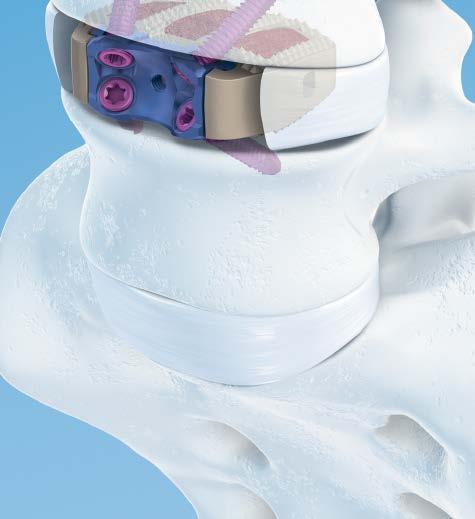
3 SYNFIX LR Spacer Implants The SYNFIX LR Implant is a stand-alone ALIF device that incorporates the benefits of an anterior plate and a radiolucent interbody spacer. The design creates a zero-profile construct and includes four locking screws that provide anterior fixation and stability. Stand-alone ALIF Biomechanically equivalent to a spacer with pedicle screws 1 PEEK spacer provides modulus of elasticity similar to cortical bone Titanium plate with locking screws provides stable fixation Zero-profile construct Spacer and plate fit completely within the disc space Anatomic shape The SYNFIX LR Implant is convex to match the anatomy of the disc space Two footprints and two lordotic angles are offered to accommodate individual patients PEEK spacer Material: PEEK (polyetheretherketone) Titanium plate Material: Titanium alloy (Ti-6Al-7Nb) Titanium screw Material: Titanium alloy (Ti-6Al-7Nb) Double-lead locking threads mate with threaded portion of plate Screw and plate fixation One-step conical locking mechanism eliminates need for blocking plate Locking screws provide stability and load transfer near the cortex of the vertebral body Four locking screws diverge to form a fixed-angle construct that creates a wedge of bone (highlighted in yellow) for fixation Self-tapping cortical threads allow largest possible core diameter for maximum fixation 1. C.M. Cain, P. Schleicher, R. Gerlach, R. Pflugmacher, F. Scholz M, F. Kandziora A New Stand-Alone Anterior Lumbar Interbody Fusion Device: Biomechanical Comparison with Established Fixation Techniques. Spine Dec 1; 30 (23): DePuy Synthes Spine SYNFIX LR Stand Alone Spacer Technique Guide


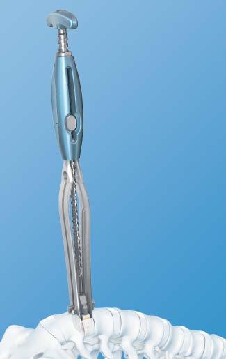
4 SYNFIX LR Spacer Simple instrumentation Once disc preparation and implant trialing are complete, only four simple instruments are needed to insert the SYNFIX LR Spacer. SYNFIX Quick Inserter/Distractor (SQUID) Inserts and distracts in one simple step, without impaction. Fixed-handle aiming device For precise positioning of the locking screws. Low-profile awl Penetrates the cortical bone for screw insertion. Low-profile driver Provides precise insertion of locking screws. Technique Guide SYNFIX LR Stand Alone Spacer DePuy Synthes Spine 3
5 AO Principles In 1958, the AO formulated four basic principles, which have become the guidelines for internal fixation. 1 They are: Anatomic reduction Stable internal fixation Preservation of blood supply Early, active mobilization The fundamental aims of fracture treatment in the limbs and fusion of the spine are the same. A specific goal in the spine is returning as much function as possible to the injured neural elements. 2,3 1. Müller ME, Allgöwer M, Schneider R, Willenegger H. Manual of Internal Fixation: Techniques Recommended by the AO-ASIF Group. 3rd ed. Berlin: Springer-Verlag; Ibid. 3. Aebi M, Thalgott JS, Webb JK. AO ASIF Principles in Spine Surgery. Berlin: Springer-Verlag; DePuy Synthes Spine SYNFIX LR Stand Alone Spacer Technique Guide
6 Indications and Contraindications Indications The DePuy Synthes Spine SYNFIX LR Spacer is a stand-alone anterior interbody fusion device indicated for use in patients with degenerative disc disease (DDD) at one or two contiguous levels from L2 to S1. These DDD patients may also have up to Grade I spondylolisthesis at the involved level(s). The interior of the spacer component of the SYNFIX LR Spacer can be packed with autograft. DDD is defined as back pain of discogenic origin with degeneration of the disc confirmed by history and radiographic studies. These patients should be skeletally mature and have had six months of nonoperative treatment. Contraindications Use of the DePuy Synthes Spine SYNFIX LR Spacer is contraindicated when: There is active systemic infection, infection localized to the site of the proposed implantation, or when the patient has demonstrated allergy or foreign body sensitivity to any of the implant materials (PEEK, titanium, aluminum and/or niobium). Severe osteoporosis may prevent adequate fixation and thus preclude the use of this or any other orthopaedic implant. Where patient anatomy or pathology prevents insertion of all four locking head screws. Please see package insert for full list of indications, contradictions, precautions and warnings. Technique Guide SYNFIX LR Stand Alone Spacer DePuy Synthes Spine 5
7 Preoperative Planning Optional technique Instruments X000045* SYNFIX LR Preoperative Planner, 26 x 32 mm, 8 X000046* SYNFIX LR Preoperative Planner, 26 x 32 mm, 12 X000047* SYNFIX LR Preoperative Planner, 30 x 38 mm, 8 X000048* SYNFIX LR Preoperative Planner, 30 x 38 mm, 12 Determine the approximate implant size by comparing the SYNFIX LR Spacer preoperative planner with a lateral radiograph of the patient s adjacent intervertebral discs. Notes: The height indicated on the template is approximately 1 mm lower than that of the actual spacer to account for penetration of the teeth into the vertebral endplate. It is recommended to select the maximum implant size, to optimize the stability of the segment through tension in the longitudinal ligaments. *Also available 6 DePuy Synthes Spine SYNFIX LR Stand Alone Spacer Technique Guide

8 Preparation The surgical approach depends on the level to be treated; however, direct anterior access is required for the insertion of the locking screws. Anterior access and approach Locate the correct operative disc level and incision location by taking a lateral flouroscopic view while holding a straight metal instrument at the side of the patient. This ensures that the incision and exposure will allow direct visualization into the disc space. Expose the operative disc level through a standard retroperitoneal approach. A mini open retroperitoneal approach can be used with the SYNFIX Mini open Instruments. Exposure The locking screws of the SYNFIX LR Spacer must be inserted from a direct anterior approach. Expose the segment to produce sufficient space on either side of the vertebral midline, equal to half the width of the implant. This allows insertion of the implant, without interference from adjacent soft tissue structures. (Two implant widths are available, 32 mm and 38 mm.) Note: When the spacer has been inserted, visualization of the entire anterior plate is necessary for insertion of the locking screws. Give proper consideration to the exposure so instrumentation can be used as depicted on the following pages. Technique Guide SYNFIX LR Stand Alone Spacer DePuy Synthes Spine 7

9 Discectomy and Endplate Preparation 1 Discectomy and endplate preparation Optional instrument PDL114* Vertebral Body Spreader, angled Create an annulotomy centered on the midline and wide enough to accommodate the SYNFIX LR Implant. A trial spacer may be used as a template to indicate the width of the annular window required. Perform a thorough discectomy, ensuring the posterolateral corners are freed of disc material. Remove the cartilaginous endplates to bleeding bone, taking care to not compromise the integrity of the bony endplates. If additional disc space distraction or remobilization is necessary, the spreader is available in the PRODISC L Total Disc Replacement instrument set. Note: Excessive removal of subchondral bone may weaken the vertebral endplate. If the entire endplate is removed, subsidence and a loss of segmental stability may result. For a safe placement, verify spreader position with the help of an intraoperative lateral x-ray. *Also available 8 DePuy Synthes Spine SYNFIX LR Stand Alone Spacer Technique Guide
. Firmly attach it to the trial spacer handle.")
10 Trial for Implant Size 2 Trial for implant size Instruments SYNFIX LR Trial Implants Handle, for Trial Spacers Optional instrument Distractor, for SYNFIX LR Spacer PDL102 Slotted Mallet Select the trial implant with the appropriate footprint and lordotic angle (see page 34). Firmly attach it to the trial spacer handle. A distractor may be used to assist with guiding the trial spacer into the disc space. To ensure that the implant is inserted symmetrically into the disc space, the central line on the distractor blades should be aligned with the anterior midline of the vertebral bodies. Controlled, light hammering on the trial spacer handle may be required to advance the trial spacer into the disc space. Important: After impacting the trial spacer handle, it may be necessary to retighten the handle. Technique Guide SYNFIX LR Stand Alone Spacer DePuy Synthes Spine 9
11 Trial for Implant Size If a tight fit is not achieved, repeat the process using incrementally larger trial spacers. Conversely, if the trial spacer cannot be inserted, repeat using incrementally smaller trial spacers. With the segment fully distracted, the trial spacer must fit firmly in the disc space. When rocking the trial spacer handle in a cranial to caudal direction, no toggling of the trial spacer should be evident. Note: Do not move the trial spacer handle laterally during removal. It is recommended that the slotted mallet be used to remove the handle if necessary. X-ray may be used to check the position of the trial implant, restoration of disc and foraminal height, and overall alignment before selecting the final SYNFIX LR Implant size. 10 DePuy Synthes Spine SYNFIX LR Stand Alone Spacer Technique Guide


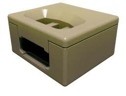
12 Trial for Implant Size Notes: Markings on the trial spacer indicate the entry points of the locking screws in the anterior aspect of the adjacent vertebrae. The distractor must be firmly held in place to prevent its ejection from the disc space and possible injury to adjacent structures. Select the maximum size, to optimize the stability of the segment. 3 Select implant size Select the SYNFIX LR Implant corresponding to the final trial spacer size and attach it to the implant holder. To facilitate selection of the implant, trial spacers are laser etched with the height, lordotic angle and footprint of the implant. Trial spacers, aiming guides and plates are color-coded by height. 4 Pack implant with autograft Instruments Packing Block, for 26 mm depth x 32 mm width SYNFIX LR Implant Packing Block, for 30 mm depth x 38 mm width SYNFIX LR Implant Cancellous Bone Impactor, 8 mm x 2.5 mm Cancellous Bone Impactor, 5.5 mm x 8.5 mm Insert the SYNFIX LR Implant into the appropriate packing block. Use a cancellous bone impactor to firmly pack the autograft material into the implant cavities. Technique Guide SYNFIX LR Stand Alone Spacer DePuy Synthes Spine 11
 Release the main thread by pushing the RELEASE button on the grip and slide the pusher fully back.")


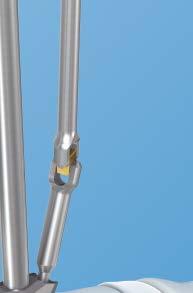
13 Insert Implant Option A: Using SQUID 5a Insert implant Instrument Main thread SYNFIX LR Quick Inserter/Distractor (SQUID) Release the main thread by pushing the RELEASE button on the grip and slide the pusher fully back. Engage/release button Place the instrument flat on the table to load the implant. Place the implant onto the bottom spring ramp. Holding both sides of the implant, engage the grooves with the spring ramp guides and gently slide the implant forward until the implant is held without sliding back. Slide the pusher up to the implant and engage the main thread by pressing the ENGAGE button. The implant is now held securely and is ready for insertion. Note: The tips of the inserter will be inserted into the disc space up to the depth stops on the spring ramps; to allow full insertion, the tips must not be spread apart. Depth stops Bottom spring ramp Ejector Pusher 12 DePuy Synthes Spine SYNFIX LR Stand Alone Spacer Technique Guide


14 Insert Implant Option A: Using SQUID Place the tips of the instrument into the disc space so the depth stops on the spring ramps touch the anterior rim of the vertebral body. The tips of the instrument are 26 mm deep and 30 mm wide. Important: The pusher will be moving toward the vertebral body and the ejector is proud above the spring ramps and stops. Be aware of soft tissue and blood vessels that may be in the path of the pusher and ejector as they move toward and push against the vertebral bodies. With the main thread engaged, turn the T-handle on the SQUID to advance the implant down the spring ramps and into the disc space. The force required to turn the T-handle will increase as the implant advances down the spring ramps and the instrument distracts the disc space. Continue turning the T-handle until the instrument is fully ejected and released. An audible click as the ramps spring back to meet each other confirms that the implant is seated and the instrument is fully ejected and released. Verify final implant position with the help of an intraoperative lateral x-ray. Note: The titanium plate and single posterior x-ray marker incorporated into the implant allow accurate intraoperative radiographic assessment of the position of the implant. The posterior x-ray marker is located approximately 2 mm from the posterior wall of the spacer. Technique Guide SYNFIX LR Stand Alone Spacer DePuy Synthes Spine 13


 all the way down on the threaded")
 all the way down (3).")
, turn the bolt until this gap disappears (5).")
.")
15 Insert Implant OPTION B: Using Implant Holder 5b Implant Holder Assembly Instruments 1 2 A Implant Holder for SYNFIX LR Implant E Wrench, 10mm Before loading the SynFix LR Implant ensure the implant holder is correctly assembled. Screw the bolt (A) all the way down on the threaded portion of the holder (1, 2). Then screw the superior cap (B) all the way down (3). A gap will be apparent between the bolt and the cap (4), turn the bolt until this gap disappears (5). Use the two wrenches to simultaneously hold the cap and counter-torque the bolt (6). 3 B DePuy Synthes Spine SYNFIX LR Stand Alone Spacer Technique Guide


16 Insert Implant OPTION B: Using Implant Holder Instruments Implant Holder, for SYNFIX LR Implant E Wrench, 10mm Optional instrument Distractor, for SYNFIX LR Implant Attach the implant holder to the SYNFIX LR Implant. The implant holder must be attached firmly to the implant during the entire implant insertion procedure to avoid damage to the implant holder or the plate. Important: Do not cross thread the implant holder into the implant. To prevent cross threading, ensure that the implant holder is perpendicular to the implant during engagement. Caution: Ensure the implant holder is assembled correctly and the cap and the bolt are counter-torqued using the two wrenches (see Implant Holder assembly on page 14 or Dissassembly and Assembly Instructions on P.45 46). Attach the selected implant two-finger tight to the implant holder. Caution: Do not over-tighten the implant holder to the implant. Make sure the implant holder and the implant are aligned to each other and that no cross-threading occurs. A distractor can be used to assist with guiding the implant into the disc space. To ensure that the implant is inserted symmetrically into the disc space, the central line on the distractor blades should be aligned with the anterior midline of the vertebral bodies. Slide the implant between the distractor blades and into the disc space. Hold the distractor firmly in place during implant insertion. Verify final implant position with the help of an intraoperative lateral x-ray. Caution: Ensure the implant holder remains tightened to the implant during the entire implant insertion procedure. Notes: The titanium plate and single posterior x-ray marker incorporated into the implant allow accurate intraoperative radiographic assessment of the position of the implant. The posterior x-ray marker is located approximately 2 mm from the posterior wall of the spacer. If it is necessary to remove the implant once it is positioned, see page 31 for implant removal procedure. Technique Guide SYNFIX LR Stand Alone Spacer DePuy Synthes Spine 15

17 Insert Implant OPTION B: Using Implant Holder Remove instruments When the implant is correctly positioned, if an optional distractor was used, loosen the locking nut on the distractor handle and release the distraction. Gently remove the distractor while the implant holder maintains the implant position. After the distractor is removed, ensure a secure fit by lightly hammering on the implant holder. Remove the implant holder by rotating the handle counterclockwise. Caution: If increased resistance is encountered during detachment, remove the implant holder with the implant attached. In case of a jammed connection between implant and implant holder, detach the implant holder from the implant using one wrench to hold the cap while detaching the implant. Restart the implant insertion procedure with Step 1 implant holder assembly on page 14. The implant should now be in its optimal position. Depending on the size of the vertebrae, the anterior edge of the implant will usually be flush to 3 mm recessed relative to the anterior aspect of the adjacent vertebrae. Note: All instruments must be removed carefully to avoid possible injury to adjacent structures. Optional instrument Handheld Retractor, curved, for SYNFIX LR Spacer The curved retractor can be used for additional tissue protection with both the mini-open and standard instrument sets. Anchor the retractor under the selected aiming device for optimal tissue retraction. For additional information about the aiming device, see pages 17 and 24. Notes: Before using the retractor, it is recommended to insert one screw to prevent implant migration. The retractor is not designed to withstand excessive forces. 16 DePuy Synthes Spine SYNFIX LR Stand Alone Spacer Technique Guide
 03.802.203 For 13.5 mm SYNFIX Spacer (gold) 03.802.205 For 15 mm SYNFIX Spacer (blue) 03.")


18 Insert Screws Using Mini-Open Instruments Screws can be inserted using either mini-open instruments or standard instruments (see pages for Steps 7b 14b). 6a Mount aiming device Instruments SYNFIX Mini-Open Implant Coupling Mini-Open Fixed-Handle Aiming Devices For 12 mm SYNFIX Spacer (light blue) For 13.5 mm SYNFIX Spacer (gold) For 15 mm SYNFIX Spacer (blue) For 17 mm SYNFIX Spacer (purple) For 19 mm SYNFIX Spacer (green) Implant coupling Fixed-handle aiming device The aiming devices are color-coded to correspond with the implant height. The aiming device ensures appropriate alignment of the screws and engagement of the locking heads into the plate. Warning: Do not use the awl or screwdriver without the appropriate aiming device. Choose the appropriate aiming device and insert the implant coupling. Insert the aiming device into exposure. The arrows located just below the handle indicate caudal and cranial orientation of the aiming device. Position the aiming device so the threaded pin (a) fits into the central hole of the plate and the lateral positioning pin (b) aligns with the plate hole for the locking screw. When the aiming device has been positioned, secure it by tightening the implant coupling knob on the top of the fixed-handle aiming device. b a Caution: If the aiming device cannot be secured to the implant, remove the implant and replace it with a new implant. See section implant removal on page 31. Note: The aiming device should fit snugly against the plate. Do not overtighten. Technique Guide SYNFIX LR Stand Alone Spacer DePuy Synthes Spine 17
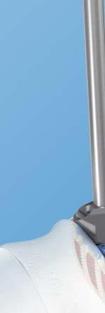
19 Insert Screws Using Mini Open Instruments 7a Open cortex Instrument Low Profile U joint Awl, for SYNFIX Mini Open Optional instrument Screw Holding Instrument, for SYNFIX LR Spacer (guiding forceps) Insert the awl into the aiming device. Prepare the vertebral body for screw insertion by applying pressure on the handle of the awl with rotational motions. Notes: Use the guiding forceps to control the tip of the awl and to avoid injury to the surrounding soft tissues or vessels. The guiding forceps can also be used for removal of the awl, to avoid damaging adjacent structures. It is not necessary to impact or completely rotate the awl to break the cortex. Rotational motions clockwise and counterclockwise are sufficient. The awl penetration is approximately 10 mm, equivalent to the purchase length of a 15 mm screw. Insert the first screw before preparing any other holes. 18 DePuy Synthes Spine SYNFIX LR Stand Alone Spacer Technique Guide

20 Insert Screws Using Mini Open Instruments 8a Insert first screw Instruments Tapered U Joint Driver for SYNFIX Mini Open Screw Holding Instrument, for SYNFIX LR Spacer (guiding forceps) Handle, with quick coupling, small Optional Instrument Screwdriver Shaft, T15 Select the appropriate screw length. Screw length should be selected to penetrate completely through the cortical bone. For a two level procedure, proper consideration should be given to the length of screw in the common vertebral body to prevent screw interference. Use the guiding forceps to control the screw while inserting into or removing from the aiming device. Important: The small handle with quick coupling is required when using the SYNFIX Mini Open Driver or the T15 screwdriver shaft. You must not use any other handle with either of these shafts. The mini open instruments can accommodate up to a 25 mm length screw. For a 30 mm screw, use the standard instruments (see pages for Steps 7b 14b). Insert the self tapping screw through the aiming device and into the pilot hole created by the awl. Important: Four (4) screws should always be used for every SYNFIX LR Spacer construct. The four locking screws should be inserted sequentially. Awl and screw insertion should be done through a SYNFIX LR Spacer aiming device, to ensure the proper locking of the screw to the plate. Technique Guide SYNFIX LR Stand Alone Spacer DePuy Synthes Spine 19


21 Insert Screws Using Mini Open Instruments 9a Tighten first screw Instruments Tapered U Joint Driver for SYNFIX Mini open Screw Holding Instrument, for SYNFIX LR Spacer (guiding forceps) Handle, with quick coupling, small Tighten the screw firmly. As soon as the ring marked on the screwdriver meets the entry point of the aiming device, the screw is locked to the plate and should not be advanced further. Warning: Excessive torque can damage or break the instruments or implant. Use four fingers for final tightening. Notes: It is difficult to remove the aiming device unless the locking head of the screw is properly seated in the plate. The guiding forceps can also be used for removal of the screwdriver to avoid damaging adjacent structures. Ring marked on screwdriver 20 DePuy Synthes Spine SYNFIX LR Stand Alone Spacer Technique Guide

22 Insert Screws Using Mini Open Instruments 10a Insert second screw Instruments Screw Holding Instrument, for SYNFIX LR Spacer (guiding forceps) Low Profile U Joint Awl, for SYNFIX Mini Open Tapered U Joint Driver for SYNFIX Mini open Handle, with quick coupling, small Insert the second screw through the second opening in the aiming device, following Steps 7a through 9a. Notes: It is difficult to remove the aiming device unless the locking head of the screw is properly seated in the plate. The guiding forceps can also be used for removal of the screwdriver to avoid damaging adjacent structures. 11a Rotate aiming device Loosen the aiming device by turning the implant coupling (1) counterclockwise four to five turns. The aiming device can be rotated 180 without disengaging completely from the plate. 1 Arrows located just below the handle indicate caudal and cranial orientation of the aiming device. Relock the aiming device by turning the implant coupling (1) clockwise. Notes: The fixed handle aiming device can be rotated in either direction. The aiming device should fit snugly against the plate, do not overtighten. Technique Guide SYNFIX LR Stand Alone Spacer DePuy Synthes Spine 21
 screws should always be used for every SYNFIX LR Spacer construct.")
23 Insert Screws Using Mini Open Instruments 12a Insert third and fourth screws For insertion of the third and fourth screws, repeat Steps 7a through 9a. Note: Four (4) screws should always be used for every SYNFIX LR Spacer construct. 13a Remove instruments When the plate is secured, remove the aiming device by turning the implant coupling on top of the handle. 22 DePuy Synthes Spine SYNFIX LR Stand Alone Spacer Technique Guide
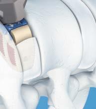
24 Insert Screws Using Mini Open Instruments 14a Verify placement The SYNFIX LR Implant is positioned optimally when the implant is completely within the confines of the vertebral bodies. Depending on the size of the vertebrae, the anterior edge of the implant will usually be flush to 3 mm recessed, relative to the anterior aspect of the adjacent vertebrae. The location of the implant relative to the vertebral bodies in the AP and lateral direction can be verified using an image intensifier. The titanium plate and single posterior x ray marker incorporated into the implant allow accurate intraoperative radiographic assessment of the position of the implant. The posterior x ray marker is approximately 2 mm from the posterior edge of the implant. X ray marker Technique Guide SYNFIX LR Stand Alone Spacer DePuy Synthes Spine 23


 fits into the central hole of the plate and the lateral positioning pin (b) aligns with the plate hole for the locking screw.")
25 Insert Screws Using Standard Instruments For inserting screws using mini-open instruments (Steps 7a 14a), see pages b Mount aiming device Instruments Aiming Device Holder, for SYNFIX LR Spacer Aiming Devices, for SYNFIX LR Spacer mm (light blue) mm (gold) mm (blue) mm (purple) mm (green) Aiming device holder Aiming device b a The aiming devices are color-coded to correspond with the implant height. The aiming device ensures appropriate alignment of the screws and engagement of the locking heads into the plate. Warning: Do not use awl or screwdriver without appropriate aiming device. Choose the appropriate aiming device and insert the implant coupling. c Insert the aiming device into exposure. Position the aiming device so the threaded pin (a) fits into the central hole of the plate and the lateral positioning pin (b) aligns with the plate hole for the locking screw. When the aiming device has been positioned, secure it by tightening the nut (c) on top of the aiming device holder. Caution: If the aiming device cannot be secured to the implant, remove the implant and replace it with a new implant. See section Implant Removal on page 31. Note: The aiming device should fit snugly against the plate, do not overtighten. 24 DePuy Synthes Spine SYNFIX LR Stand Alone Spacer Technique Guide
 03.802.")
26 Insert Screws Using Standard Instruments 7b Open cortex Instruments Cortex Opener, for SYNFIX LR Spacer (awl) Screw Holding Instrument, for SYNFIX LR Spacer (guiding forceps) For better visualization of the operative site, the aiming device holder can be removed, leaving the aiming device attached to the plate. Insert the awl into the aiming device. Prepare the vertebral body for screw insertion by applying pressure on the handle of the awl with rotational motions. Guiding forceps should be used to ensure directional control of the awl tip. Notes: Use the guiding forceps to control the tip of the awl and to avoid injury to the surrounding soft tissues or vessels. The guiding forceps can also be used for removal of the awl, to avoid damaging adjacent structures. It is not necessary to impact or completely rotate the awl to break the cortex. Rotational motions clockwise and counterclockwise are sufficient. The awl penetration is approximately 10 mm, equivalent to the purchase length of a 15 mm screw. Insert the first screw before preparing any other holes. Technique Guide SYNFIX LR Stand Alone Spacer DePuy Synthes Spine 25
27 Insert Screws Using Standard Instruments 8b Insert first screw Instruments Screwdriver, for SYNFIX LR Spacer Screw Holding Instrument, for SYNFIX LR Spacer (guiding forceps) Optional Instruments Screwdriver Shaft, T Handle, with quick coupling, small Select the appropriate screw length. Screw length should be selected to penetrate completely through the cortical bone. For a two-level procedure, proper consideration should be given to the length of screw in the common vertebral body to prevent screw interference. Insert the self-tapping screws with the screwdriver and the guiding forceps, through the aiming device and into the pilot hole created by the awl. Important: The small handle with quick coupling is required when using the T15 screwdriver shaft. You must not use any other handle with this shaft. Four (4) screws should always be used for every SYNFIX LR Spacer construct. The four locking screws should be inserted sequentially. Awl and screw insertion should be done through a SYNFIX LR Spacer aiming device to ensure the proper locking of the screw to the plate. Notes: The guiding forceps allow control of the screw during insertion, to avoid damage to the surrounding soft tissue or vessels. The guiding forceps can also be used for removal of the screwdriver to avoid damaging adjacent structures. 26 DePuy Synthes Spine SYNFIX LR Stand Alone Spacer Technique Guide

28 Insert Screws Using Standard Instruments 9b Tighten the first screw Instruments Screwdriver, for SYNFIX LR Spacer Screw Holding Instrument, for SYNFIX LR Spacer (guiding forceps) Tighten the screw firmly. As soon as the ring marked on the screwdriver meets the entry point of the aiming device, the screw is locked to the plate and should not be advanced further. Warning: Excessive torque can damage or break the instruments or implant. Use four fingers for final tightening. Notes: It is difficult to remove the aiming device unless the locking head of the screw is properly seated in the plate. The guiding forceps can also be used for removal of the screwdriver to avoid damaging adjacent structures. Ring marked on screwdriver Technique Guide SYNFIX LR Stand Alone Spacer DePuy Synthes Spine 27
 03.802.")
29 Insert Screws Using Standard Instruments 10b Insert second screw Instruments Cortex Opener, for SYNFIX LR Spacer (awl) Screwdriver, for SYNFIX LR Spacer Screw Holding Instrument, for SYNFIX LR Spacer (guiding forceps) Insert the second screw following Steps 7b through 9b through the second opening in the aiming device. Use the guiding forceps, to ensure directional control. Notes: It is difficult to remove the aiming device unless the locking head of the screw is properly seated in the plate. The guiding forceps can also be used for removal of the screwdriver to avoid damaging adjacent structures. 11b Rotate aiming device Instrument Aiming Device Holder, for SYNFIX LR Spacer If the aiming device handle was removed, reattach it to the aiming device before rotation. Loosen the aiming device by turning the nut (1) counterclockwise four to five turns. The aiming device can be rotated 180, without disengaging it completely from the plate. Relock the aiming device by turning the nut (1) clockwise. Notes: Rotating the aiming device clockwise will ensure that the aiming device handle does not loosen unintentionally. The aiming device should fit snugly against the plate, do not overtighten. 28 DePuy Synthes Spine SYNFIX LR Stand Alone Spacer Technique Guide
 screws should always be used for every SYNFIX LR Spacer construct.")
30 Insert Screws Using Standard Instruments 12b Insert third and fourth screws For insertion of the third and fourth screws, repeat Steps 7b through 9b. Note: Four (4) screws should always be used for every SYNFIX LR Spacer construct. 13b Remove instruments When the plate is secured, remove the aiming device by turning the nut on top of the aiming device holder. Technique Guide SYNFIX LR Stand Alone Spacer DePuy Synthes Spine 29

31 Insert Screws Using Standard Instruments 14b Verify placement The SYNFIX LR Implant is positioned optimally when the implant is completely within the confines of the vertebral bodies. Depending on the size of the vertebrae, the anterior edge of the implant will usually be flush to 3 mm recessed, relative to the anterior aspect of the adjacent vertebrae. The location of the implant relative to the vertebral bodies in the AP and lateral direction can be verified using an image intensifier. The titanium plate and single posterior x-ray marker incorporated into the implant allow accurate intraoperative radiographic assessment of the position of the implant. The posterior x-ray marker is approximately 2 mm from the posterior edge of the implant. X-ray marker 30 DePuy Synthes Spine SYNFIX LR Stand Alone Spacer Technique Guide

32 Implant Removal Procedure Instrument Holding Forceps The holding forceps can be used to retrieve the SYNFIX LR Implant. Once the implant is removed, it may not be reused. If cross threading occurs while engaging the implant holder with the SYNFIX LR Implant, the threaded end of the implant holder may fragment in the central hole of the plate. If this occurs, the threaded fragment must be removed. Connect forceps to implant Engage the SYNFIX LR Implant with the forceps at one of the four screw holes. Remove implant Apply a gentle extraction force to the forceps to remove the implant. After removal of the implant, ensure that all components are removed from the intervertebral disc space. Technique Guide SYNFIX LR Stand Alone Spacer DePuy Synthes Spine 31
 angle 26 mm depth 32 mm width 30 mm depth 38 mm width height posterior height* Implants shown actual size 26 mm x 32 mm Lordotic angle Height (mm) Posterior Height (mm)")
 Posterior Height (mm) Color 08.802.018S 8º 12 8.")

33 Implants SYNFIX LR Implants Supplied sterile and preassembled (spacer with anterior plate) Plate components are color coded by height Cage component: PEEK (polyetheretherketone) Plate component: Titanium alloy (Ti 6Al 7Nb) angle 26 mm depth 32 mm width 30 mm depth 38 mm width height posterior height* Implants shown actual size 26 mm x 32 mm Lordotic angle Height (mm) Posterior Height (mm) Color S 8º 12 9 Light Blue S 8º Gold S 8º Blue S 8º Purple S 8º Green S 12º Light Blue S 12º Gold S 12º Blue S 12º Purple S 12º Green 30 mm x 38 mm Lordotic angle Height (mm) Posterior Height (mm) Color S 8º Light Blue S 8º Gold S 8º Blue S 8º Purple S 8º Green S 12º 12 7 Light Blue S 12º Gold S 12º Blue S 12º Purple S 12º Green *Posterior height is measured from the top of the most posterior teeth. Total combined height of teeth is 1.8 mm. 32 DePuy Synthes Spine SYNFIX LR Stand Alone Spacer Technique Guide
 Designed to more easily penetrate dense sclerotic bone Length (mm) Bone Purchase (mm) 04.802.210 15 10 04.802.211 20 15 04.")
34 Implants 4.0 mm Titanium Locking Screws Self-tapping Titanium alloy (Ti-6Al-7Nb) Length (mm) Bone Purchase (mm) purchase** length 42º 30º 4.0 mm Titanium Locking Screws, fine tip Self-tapping Titanium alloy (Ti-6Al-7Nb) Designed to more easily penetrate dense sclerotic bone Length (mm) Bone Purchase (mm) purchase** length **Bone purchase is approximately 5 mm less than length. Technique Guide SYNFIX LR Stand Alone Spacer DePuy Synthes Spine 33
 Color 03.802.016 03.802.018 8º 12 Light Blue 03.802.000 03.802.008 8º 13.5 Gold 03.802.001 03.")

35 Implants SYNFIX LR Trial Implants Color-coded by height Color corresponds to the SYNFIX LR Implant plate component 26 mm depth 30 mm depth 32 mm width 38 mm width Trial Implants shown actual size 26 mm x 32 mm 30 mm x 38 mm Lordotic angle Height (mm) Color º 12 Light Blue º 13.5 Gold º 15 Blue º 17 Purple º 19 Green º 12 Light Blue º 13.5 Gold º 15 Blue º 17 Purple º 19 Green 34 DePuy Synthes Spine SYNFIX LR Stand Alone Spacer Technique Guide
 03.802.036 Aiming Device, 15 mm, for SYNFIX LR Spacer (blue) 03.802.033 Aiming Device, 17 mm, for SYNFIX LR Spacer (purple) 03.802.034 Aiming Device, 19 mm, for SYNFIX LR Spacer (green) If a standard aiming device is used, a radius of approximately 4.")
 03.802.243 13.5 mm Aiming Device Modified Guide Opening, for SYNFIX LR Spacer (gold) 03.802.245 15 mm Aiming Device Modified Guide Opening, for SYNFIX LR Spacer ( blue) 03.")
36 Instruments SYNFIX LR Aiming Devices Standard Aiming Device (required exposure 8 10 cm) ~4.3 cm Aiming Device, 12 mm, for SYNFIX LR Spacer (light blue) Aiming Device, 13.5 mm, for SYNFIX LR Spacer (gold) Aiming Device, 15 mm, for SYNFIX LR Spacer (blue) Aiming Device, 17 mm, for SYNFIX LR Spacer (purple) Aiming Device, 19 mm, for SYNFIX LR Spacer (green) If a standard aiming device is used, a radius of approximately 4.3 cm is required. It enables guidance of the awl and the screwdriver while ensuring the secure insertion of all screws. Modified Aiming Device (required exposure 7 9 cm) Also Available: mm Aiming Device Modified Guide Opening, for SYNFIX LR Spacer (light blue) mm Aiming Device Modified Guide Opening, for SYNFIX LR Spacer (gold) mm Aiming Device Modified Guide Opening, for SYNFIX LR Spacer ( blue) mm Aiming Device Modified Guide Opening, for SYNFIX LR Spacer (purple) mm Aiming Device Modified Guide Opening, for SYNFIX LR Spacer (green) The modified aiming device has a relief that allows the awl to be inserted more medially, similar to the mini open instruments. The area shaded red indicates the change made to the standard aiming device. Guidance is established just before the awl penetrates the cortex. Technique Guide SYNFIX LR Stand Alone Spacer DePuy Synthes Spine 35


37 Instruments Aiming Device Mini-Open with Fixed Handle (required exposure 5 7 cm) ~2.7 cm Mini Open Fixed Handle Aiming Device, for 12 mm SYNFIX Spacer Mini Open Fixed Handle Aiming Device, for 13.5 mm SYNFIX Spacer Mini Open Fixed Handle Aiming Device, for 15 mm SYNFIX Spacer Mini Open Fixed Handle Aiming Device, for 17 mm SYNFIX Spacer Mini Open Fixed Handle Aiming Device, for 19 mm SYNFIX Spacer When using the mini open aiming devices, a radius of approximately 2.7 cm is required. It enables guidance of the awl and the screwdriver while ensuring the secure insertion of all screws. Trade-off between guidance and exposure There is a trade off between guidance and exposure. The standard aiming device offers the best guidance but also requires a larger exposure. The mini open device requires a smaller exposure, but offers minimal guidance. The modified aiming device offers slightly less guidance than the standard aiming device, but allows for a smaller incision. Standard aiming device Mini open aiming device Modified aiming device 36 DePuy Synthes Spine SYNFIX LR Stand Alone Spacer Technique Guide
38 Instruments Screwdriver Shaft, T Aiming Device Holder, for SYNFIX LR Spacer Cortex Opener, for SYNFIX LR Spacer Screwdriver, for SYNFIX LR Spacer Screw Holding Instrument, for SYNFIX LR Spacer Implant Holder, for SYNFIX LR Spacer For use with Distractor ( ) Technique Guide SYNFIX LR Stand Alone Spacer DePuy Synthes Spine 37
 03.802.200 SYNFIX Mini Open Implant Coupling 03.802.230 Low Profile U Joint Awl, for SYNFIX Mini Open 03.")
39 Instruments Packing Block, for 26 mm depth x 32 mm width SYNFIX LR Spacer Packing Block, for 30 mm depth x 38 mm width SYNFIX LR Spacer SYNFIX LR Quick Inserter/Distractor (SQUID) SYNFIX Mini Open Implant Coupling Low Profile U Joint Awl, for SYNFIX Mini Open Handheld Retractor, curved, for SYNFIX LR Spacer Tapered U Joint Driver, for SYNFIX Mini Open 38 DePuy Synthes Spine SYNFIX LR Stand Alone Spacer Technique Guide


40 Instruments Handle, with quick coupling, small Holding Forceps Handle, for Trial Spacers Cancellous Bone Impactor, 8 mm x 2.5 mm Cancellous Bone Impactor, 5.5 mm x 8.5 mm Distractor, for SYNFIX LR Spacer E Wrench, 10 mm Technique Guide SYNFIX LR Stand Alone Spacer DePuy Synthes Spine 39


41 SYNFIX LR Standard Instrument Set ( ) Graphic Case Graphic Case, for SYNFIX LR Standard Instruments Instruments Screwdriver Shaft, T Aiming Device Holder, for SYNFIX LR Spacer Aiming Devices, for SYNFIX LR Spacer mm mm mm mm mm Cortex Opener, for SYNFIX LR Spacer Screwdriver, for SYNFIX LR Spacer Screw Holding Instrument, for SYNFIX LR Spacer Implant Holder, for SYNFIX LR Spacer Packing Block, for 26 mm depth x 32 mm width SYNFIX LR Spacer Packing Block, for 30 mm depth x 38 mm width SYNFIX LR Spacer Handle, with quick coupling, small Cancellous Bone Impactor, 8 mm x 2.5 mm Cancellous Bone Impactor, 5.5 mm x 8.5 mm Distractor, for SYNFIX LR Spacer Also Available Module for SYNFIX LR Aiming Devices Aiming Devices, Modified Guide Opening, for SYNFIX LR Spacer mm mm mm mm mm E Wrench, 10 mm For detailed cleaning and sterilization instructions, please refer to: In Canada, the cleaning and sterilization instructions will be provided with the Loaner shipments. 40 DePuy Synthes Spine SYNFIX LR Stand Alone Spacer Technique Guide
 03.802.200 SynFix Mini-Open Implant Coupling, 2 ea. Mini-Open Fixed Handle Aiming Devices, for SYNFIX LR Spacer 03.802.202 12 mm 03.802.203 13.")

42 SYNFIX LR Mini-Open Instrument Set ( ) Graphic Case Graphic Case, for SynFix Mini-Open Instruments Instruments Screw Holding Instrument, for SYNFIX LR Spacer Implant Holder, for SYNFIX LR Spacer SynFix LR Synthes Quick Inserter/Distractor (SQUID) SynFix Mini-Open Implant Coupling, 2 ea. Mini-Open Fixed Handle Aiming Devices, for SYNFIX LR Spacer mm mm mm mm mm Low Profile U-Joint Awl, for SynFix Mini-Open, 2 ea Handheld Retractor, curved, for SYNFIX LR Spacer Tapered U-Joint Driver for SynFix Mini-Open, 2 ea Handle, with quick coupling, small Holding Forceps Distractor, for SYNFIX LR Spacer Also Available PDL114 Vertebral Body Spreader, angled E Wrench, 10 mm Technique Guide SYNFIX LR Stand Alone Spacer DePuy Synthes Spine 41

43 SYNFIX LR Trial Spacer and Screw Set ( ) Graphic Case Graphic Case, for SYNFIX LR Trial Spacers and Screws Instruments SYNFIX LR Trial Implants * Screwdriver Shaft, T Handle, for Trial Spacers, 2 ea. Implants 4.0 mm Titanium Locking Screws, for SYNFIX LR Spacer mm, 5 ea mm, 10 ea mm, 10 ea mm, 5 ea. 4.0 mm Titanium Locking Screws, Fine Tip for SYNFIX LR Spacer mm, 5 ea mm, 8 ea mm, 8 ea mm, 5 ea. *For full listing, see page DePuy Synthes Spine SYNFIX LR Stand Alone Spacer Technique Guide

44 SYNFIX LR Implant Set ( ) Carry Case Carry Case, for SYNFIX LR Implants Implants S S S S S S S S S S S S S S S S S S S S SYNFIX LR Spacer, 8, 26 mm depth x 32 mm width, sterile 12 mm height, 2 ea mm height, 2 ea. 15 mm height, 2 ea. 17 mm height 19 mm height SYNFIX LR Spacer, 12, 26 mm depth x 32 mm width, sterile 12 mm height, 2 ea mm height, 2 ea. 15 mm height, 2 ea. 17 mm height 19 mm height SYNFIX LR Spacer, 8, 30 mm depth x 38 mm width, sterile 12 mm height 13.5 mm height, 2 ea. 15 mm height, 2 ea. 17 mm height 19 mm height SYNFIX LR Spacer, 12, 30 mm depth x 38 mm width, sterile 12 mm height 13.5 mm height, 2 ea. 15 mm height, 2 ea. 17 mm height 19 mm height Technique Guide SYNFIX LR Stand Alone Spacer DePuy Synthes Spine 43
45 SYNFIX LR System ( ) Consists of Sets: SYNFIX LR Standard Instrument Set SYNFIX LR Mini-Open Instrument Set SYNFIX LR Trial Spacer and Screw Set SYNFIX LR Implant Set 44 DePuy Synthes Spine SYNFIX LR Stand Alone Spacer Technique Guide

46 Disassembly Instruction 1 10 mm E Technique Guide SYNFIX LR Stand Alone Spacer DePuy Synthes Spine 45

47 Assembly Instruction mm E DePuy Synthes Spine SYNFIX LR Stand Alone Spacer Technique Guide
48 Limited Warranty and Disclaimer: DePuy Spine, Inc. products are sold with a limited warranty to the original purchaser against defects in workmanship and materials. Any other express or implied warranties, including warranties of merchantability or fitness, are hereby disclaimed. WARNING: In the USA, this product has labeling limitations. See package insert for complete information. CAUTION: USA Law restricts these devices to sale by or on the order of a physician. To order in the U.S. call, Johnson & Johnson Health Care Systems Inc. Customer Support Services at Not all products are currently available in all markets. Manufactured or distributed in the United States by: Synthes USA, LLC 1101 Synthes Avenue Monument, CO DePuy Synthes Spine, a division of DOI All rights reserved. DSUS/SPN/0414/0124
Luminary ALIF. Disc preparation and implant insertion instruments.
 Luminary ALIF. Disc preparation and implant insertion instruments. Technique Guide Instruments and implants approved by the AO Foundation Table of Contents Introduction Luminary ALIF 2 AO Principles 4
Thoracolumbar Spine Locking Plate (TSLP) System. A low-profile plating system for anterior stabilization of the thoracic and lumbar spine.
 System. A low-profile plating system for anterior stabilization of the thoracic and lumbar spine.") Thoracolumbar Spine Locking Plate (TSLP) System. A low-profile plating system for anterior stabilization of the thoracic and lumbar spine. Technique Guide Instruments and implants approved by the AO Foundation
Thoracolumbar Spine Locking Plate (TSLP) System. A low-profile plating system for anterior stabilization of the thoracic and lumbar spine. Technique Guide Instruments and implants approved by the AO Foundation
SYNFIX EVOLUTION SECURED SPACER SYSTEM
 SYNFIX EVOLUTION SECURED SPACER SYSTEM Instruments and implants for stand-alone anterior lumbar interbody fusion Instruments and implants approved by the AO Foundation. This publication is not intended
Technique Guide. T-PAL. Transforaminal posterior atraumatic lumbar spacer system.
 Technique Guide T-PAL. Transforaminal posterior atraumatic lumbar spacer system. Table of Contents Introduction T-PAL 2 AO Principles 4 Indications and Contraindications 5 Surgical Technique Preparation
SYNCAGE EVOLUTION. This publication is not intended for distribution in the USA. SURGICAL TECHNIQUE
 SYNCAGE EVOLUTION This publication is not intended for distribution in the USA. SURGICAL TECHNIQUE Image intensifier control Warning This description alone does not provide sufficient background for direct
Replacement Device A modular expandable radiolucent vertebral body replacement system
 XRL Vertebral Body Replacement Device A modular expandable radiolucent vertebral body replacement system SURGICAL TECHNIQUE TABLE OF CONTENTS Introduction XRL System 2 AO Principles 5 Indications and Contraindications
Low Bend Distal Tibia Plates
 Part of the DePuy Synthes Locking Compression Plate (LCP ) System 3.5 mm LCP Low Bend Medial Distal Tibia Plates Surgical Technique Table of Contents Introduction 3.5 mm LCP Low Bend Medial Distal Tibia
Zero-P Instruments and Implants. Zero-profile anterior cervical interbody fusion (ACIF) device.
 device.") Zero-P Instruments and Implants. Zero-profile anterior cervical interbody fusion (ACIF) device. Technique Guide Instruments and implants approved by the AO Foundation Table of Contents Introduction Zero-P
Zero-P Instruments and Implants. Zero-profile anterior cervical interbody fusion (ACIF) device. Technique Guide Instruments and implants approved by the AO Foundation Table of Contents Introduction Zero-P
Advantage ALIF. Keith Shevlin Managing Director
 Advantage ALIF Unit 10, 9-11 Myrtle Street, Crows Nest NSW 2065 Keith Shevlin Managing Director keithshevlin@precisionsurgical.com.au Advantage ALIF Introduction & Indications for Use 1 Surgical Technique
Technique Guide. Zero-P VA. Variable angle zero-profile anterior cervical interbody fusion (ACIF) device.
 device.") Technique Guide Zero-P VA. Variable angle zero-profile anterior cervical interbody fusion (ACIF) device. Image intensifier control Warning This description alone does not provide sufficient background
Technique Guide Zero-P VA. Variable angle zero-profile anterior cervical interbody fusion (ACIF) device. Image intensifier control Warning This description alone does not provide sufficient background
VECTRA-T SURGICAL TECHNIQUE. The Translational Anterior Cervical Palate System. This publication is not intended for distribution in the USA.
 VECTRA-T The Translational Anterior Cervical Palate System This publication is not intended for distribution in the USA. SURGICAL TECHNIQUE Image intensifier control This description alone does not provide
Synex System TECHNIQUE GUIDE. An expandable vertebral body replacement device
 Synex System TECHNIQUE GUIDE An expandable vertebral body replacement device Original Instruments and Implants of the Association for the Study of Internal Fixation AO ASIF Synex System Overview The Synex
USS Variable Axis Screw (VAS) System. For posterior fixation of the lumbar spine.
 System. For posterior fixation of the lumbar spine.") USS Variable Axis Screw (VAS) System. For posterior fixation of the lumbar spine. Technique Guide Instruments and implants approved by the AO Foundation Table of Contents Introduction USS Variable Axis
USS Variable Axis Screw (VAS) System. For posterior fixation of the lumbar spine. Technique Guide Instruments and implants approved by the AO Foundation Table of Contents Introduction USS Variable Axis
Thoracolumbar Anterior Compression (TAC) System. Allows distraction, compression, and lateral fixation of the lower thoracic and lumbar spine.
 System. Allows distraction, compression, and lateral fixation of the lower thoracic and lumbar spine.") Thoracolumbar Anterior Compression (TAC) System. Allows distraction, compression, and lateral fixation of the lower thoracic and lumbar spine. Technique Guide Instruments and implants approved by the AO
Thoracolumbar Anterior Compression (TAC) System. Allows distraction, compression, and lateral fixation of the lower thoracic and lumbar spine. Technique Guide Instruments and implants approved by the AO
MODULAR DESIGN OFFERS FREEDOM OF CHOICE. Surgical Technique
 MODULAR DESIGN OFFERS FREEDOM OF CHOICE Surgical Technique Joint Spine Sports Med MectaLIF Anterior Surgical Technique 2 INDEX 1. INTRODUCTION 4 1.1 Material & Marker 5 2. INDICATIONS 5 3. CONTRAINDICATIONS
Interbody fusion cage for the transforaminal approach. Travios. Surgical Technique
 Interbody fusion cage for the transforaminal approach Travios Surgical Technique Image intensifier control This description alone does not provide sufficient background for direct use of DePuy Synthes
XRL A modular expandable radiolucent vertebral body replacement system
 XRL A modular expandable radiolucent vertebral body replacement system This publication is not intended for distribution in the USA. SURGICAL TECHNIQUE Table of Contents Introduction XRL 2 AO Spine Principles
Instruments and implants for stand-alone anterior lumbar interbody fusion (ALIF) SynFix-LR System. Surgical Technique
 SynFix-LR System. Surgical Technique") Instruments and implants for stand-alone anterior lumbar interbody fusion (ALIF) SynFix-LR System Surgical Technique Image intensifier control This description alone does not provide sufficient background
Instruments and implants for stand-alone anterior lumbar interbody fusion (ALIF) SynFix-LR System Surgical Technique Image intensifier control This description alone does not provide sufficient background
SynFix-LR System. Instruments and implants for stand-alone anterior lumbar interbody fusion (ALIF).
.") SynFix-LR System. Instruments and implants for stand-alone anterior lumbar interbody fusion (ALIF). Technique Guide This publication is not intended for distribution in the USA. Instruments and implants
SynFix-LR System. Instruments and implants for stand-alone anterior lumbar interbody fusion (ALIF). Technique Guide This publication is not intended for distribution in the USA. Instruments and implants
3.5 mm LCP Low Bend Medial Distal Tibia Plate Aiming Instruments
 Part of the 3.5 mm LCP 3.5 mm LCP Low Bend Medial Distal Tibia Plate Aiming Instruments Surgical Technique TABLE OF CONTENTS INTRODUCTION 3.5 mm LCP Low Bend Medial Distal Tibia Plate 2 Aiming Instruments
EXACTECH SPINE. Operative Technique. Cervical Spacer System. Surgeon focused. Patient driven. TM
 EXACTECH SPINE Operative Technique Cervical Spacer System Surgeon focused. Patient driven. TM ACAPELLA ONE Acapella One Cervical Spacer System is an anterior cervical discectomy and fusion device with
SynCage. Surgical Technique. This publication is not intended for distribution in the USA. Instruments and implants approved by the AO Foundation.
 SynCage Surgical Technique This publication is not intended for distribution in the USA. Instruments and implants approved by the AO Foundation. Image intensifier control Warning This description alone
Trephine System. Principle-based anterior lumbar interbody fusion.
 Trephine System. Principle-based anterior lumbar interbody fusion. Technique Guide Instruments and implants approved by the AO Foundation Table of Contents Introduction Trephine System 2 AO Principles
Solitaire Anterior Spinal System
 Surgical Technique Solitaire Anterior Spinal System Independent Stabilization for the Anterior Column Available in Titanium and Contents Introduction... Page 1 Design Features... Page 2 Instruments...
ECD EXPANDABLE CORPECTOMY DEVICE Continuously Expandable Vertebral Body Replacement for Tumour Cases
 ECD EXPANDABLE CORPECTOMY DEVICE Continuously Expandable Vertebral Body Replacement for Tumour Cases Instruments and implants approved by the AO Foundation. This publication is not intended for distribution
3.5 mm LCP Extra-articular Distal Humerus Plate
 Part of the DePuy Synthes Locking Compression Plate (LCP ) System 3.5 mm LCP Extra-articular Distal Humerus Plate Surgical Technique Table of Contents Introduction 3.5 mm LCP Extra-articular Distal Humerus
Technique Guide. 3.5 mm LCP Low Bend Medial Distal Tibia Plates. Part of the Synthes locking compression plate (LCP) system.
 system.") Technique Guide 3.5 mm LCP Low Bend Medial Distal Tibia Plates. Part of the Synthes locking compression plate (LCP) system. Table of Contents Introduction 3.5 mm LCP Low Bend Medial Distal Tibia Plates
Technique Guide 3.5 mm LCP Low Bend Medial Distal Tibia Plates. Part of the Synthes locking compression plate (LCP) system. Table of Contents Introduction 3.5 mm LCP Low Bend Medial Distal Tibia Plates
nva Anterior Lumbar Interbody Fusion System
 nva Anterior Lumbar Interbody Fusion System 1 IMPORTANT INFORMATION FOR PHYSICIANS, SURGEONS, AND/OR STAFF The nv a, nv p, and nv t are an intervertebral body fusion device used in the lumbar spine following
Technique Guide. ECD Expandable Corpectomy Device. Continuously Expandable Vertebral Body Replacement for Tumour Cases.
 Technique Guide ECD Expandable Corpectomy Device. Continuously Expandable Vertebral Body Replacement for Tumour Cases. Table of Contents Introduction Overview 2 AO ASIF Principles 4 Indications and Contraindications
3.5 mm LCP Olecranon Plates
 Part of the DePuy Synthes Locking Compression Plate (LCP ) System 3.5 mm LCP Olecranon Plates Surgical Technique Table of Contents Introduction 3.5 mm LCP Olecranon Plates 2 AO Principles 3 Indications
Occipital Cervical Fusion System. Implants and instruments designed to optimize fixation to the occiput.
 Occipital Cervical Fusion System. Implants and instruments designed to optimize fixation to the occiput. Technique Guide and implants approved by the AO Foundation Table of Contents Introduction Occipital
BAK/C Cervical Anterior Interbody Fusion System
 Surgical Technique BAK/C Cervical Anterior Interbody Fusion System The Comfortable Choice for Cervical Fusion BAK/C Cervical Surgical Technique 1 The BAK/C Cervical Fusion System is an alternative to conventional
3.5 mm Clavicle Hook Plates
 A Single Solution for Lateral Clavicle Fractures and Acromioclavicular Joint Dislocations 3.5 mm Clavicle Hook Plates Surgical Technique Discontinued December 2017 DSUS/TRM/1016/1126(1) Table of Contents
TSLP Thoracolumbar Spine Locking Plate
 Anterior thoracolumbar spine locking plate TSLP Thoracolumbar Spine Locking Plate Surgical Technique Image intensifier control This description alone does not provide sufficient background for direct use
product overview Implant heights range from 8mm-20mm in 2mm increments, with two lordocic angle options of 6 and 12.
 ETHOS A-Spacer PEEK System Surgical Technique Guide Synchronizing Medical Innovation with Global Markets product overview The SyncMedical Ethos PEEK IBF System is an intervertebral body fusion device for
Part of the DePuy Synthes Locking Compression Plate (LCP ) System. 3.5 mm LCP Medial Proximal Tibia Plates
 System. 3.5 mm LCP Medial Proximal Tibia Plates") Part of the DePuy Synthes Locking Compression Plate (LCP ) System 3.5 mm LCP Medial Proximal Tibia Plates Surgical Technique Table of Contents Introduction 3.5 mm LCP Medial Proximal Tibia Plates 2 AO
Part of the DePuy Synthes Locking Compression Plate (LCP ) System 3.5 mm LCP Medial Proximal Tibia Plates Surgical Technique Table of Contents Introduction 3.5 mm LCP Medial Proximal Tibia Plates 2 AO
SynCage-C short. Surgical Technique. This publication is not intended for distribution in the USA.
 SynCage-C short Surgical Technique This publication is not intended for distribution in the USA. Instruments and implants approved by the AO Foundation. Table of contents Implants 2 Indications/contra-indications
Cannulated Pediatric Osteotomy System (CAPOS)
") A Single System of Osteotomy Blade Plates and Cannulated Instrumentation Cannulated Pediatric Osteotomy System (CAPOS) Surgical Technique Table of Contents Introduction Cannulated Pediatric Osteotomy System
A Single System of Osteotomy Blade Plates and Cannulated Instrumentation Cannulated Pediatric Osteotomy System (CAPOS) Surgical Technique Table of Contents Introduction Cannulated Pediatric Osteotomy System
The Versatile Polyaxial Solution for the Universal Spine Systems. USS II Polyaxial. Surgical Technique
 The Versatile Polyaxial Solution for the Universal Spine Systems USS II Polyaxial Surgical Technique Image intensifier control This description alone does not provide sufficient background for direct use
Imola Lateral IBF System Surgical Technique
 Imola Lateral IBF System Surgical Technique IMOLA CIRCUIT TABLE OF CONTENTS Design Rationale Instructions for Use Surgical Technique 1. Table Mounting 2. Surgical Planning & Targeting 3. Access and Preparation
CSLP Quick Lock Screws. Preassembled expansionhead screw and locking screw for use with Cervical Spine Locking Plates (CSLP).
.") CSLP Quick Lock Screws. Preassembled expansionhead screw and locking screw for use with Cervical Spine Locking Plates (CSLP). Technique Guide Instruments and implants approved by the AO Foundation Table
CSLP Quick Lock Screws. Preassembled expansionhead screw and locking screw for use with Cervical Spine Locking Plates (CSLP). Technique Guide Instruments and implants approved by the AO Foundation Table
3.5 mm LCP Clavicle Hook Plates
 Part of the Synthes Locking Compression Plate (LCP ) System 3.5 mm LCP Clavicle Hook Plates Surgical Technique Table of Contents Introduction 3.5 mm LCP Clavicle Hook Plates 2 AO Principles 4 Indications
Distal Radius Plate Instrument and Implant Set. Discontinued December 2017 DSUS/TRM/0916/1063(1)
") Distal Radius Plate Instrument and Implant Set Surgical Technique Discontinued December 2017 DSUS/TRM/0916/1063(1) The Distal Radius Plates Indications For fixation of fractures and osteotomies, including
Distal Radius Plate Instrument and Implant Set Surgical Technique Discontinued December 2017 DSUS/TRM/0916/1063(1) The Distal Radius Plates Indications For fixation of fractures and osteotomies, including
Low Profile Neuro Plating System. Surgical Technique
 Low Profile Neuro Plating System Surgical Technique TABLE OF CONTENTS INTRODUCTION Low Profile Neuro Plating System 2 SURGICAL TECHNIQUE Technique 5 PRODUCT INFORMATION Low Profile Neuro Plates 10 Low
nvt Transforaminal Lumbar Interbody Fusion System
 nvt Transforaminal Lumbar Interbody Fusion System 1 IMPORTANT INFORMATION FOR PHYSICIANS, SURGEONS, AND/OR STAFF The nv a, nv p, and nv t are an intervertebral body fusion device used in the lumbar spine
Posterior Lumbar Interbody Fusion System
 Px Posterior Lumbar Interbody Fusion System Px PEEK INTERBODY FUSION SYSTEM INDICATIONS FOR USE The Innovasis Px PEEK IBF System is an intervertebral body fusion device for use in patients with degenerative
C-THRU Anterior Spinal System
 C-THRU Anterior Spinal System Surgical Technique Manufactured From Contents Introduction... Page 1 Design Features... Page 2 Instruments... Page 3 Surgical Technique... Page 4 Product Information... Page
Surgical technique. SynCage-C short
 Surgical technique SynCage-C short Table of contents Implants 2 Indications/contra-indications 3 Surgical technique 4 Image intensifier control Warning This description is not sufficient for immediate
The Locking Calcaneal Plate Instrument and Implant Sets
 Part of the DePuy Synthes Locking Compression Plate (LCP ) System The Locking Calcaneal Plate Instrument and Implant Sets Surgical Technique Table of Contents Introduction Locking Calcaneal Plate 2 AO
Alamo C. Cervical Interbody System Surgical Technique. An Alliance Partners Company
 Cervical Interbody System Surgical Technique Table of Contents Indications for Use................................1 Device Description............................... 1 Alamo C Instruments..............................
nvp Posterior Lumbar Interbody Fusion System
 nvp Posterior Lumbar Interbody Fusion System 1 IMPORTANT INFORMATION FOR PHYSICIANS, SURGEONS, AND/OR STAFF The nv a, nv p, and nv t are an intervertebral body fusion device used in the lumbar spine following
Cervical Spacer System surgical technique
 Blackhawk TM Cervical Spacer System surgical technique Blackhawk TM The BLACKHAWK Cervical Spacer System is designed to provide biomechanical stabilization as an adjunct to fusion. Spinal fixation should
Spinal Correction FRA Spacer System. For use with the Small Stature FRA Spacer and the FRA Spacer.
 Spinal Correction FRA Spacer System. For use with the Small Stature FRA Spacer and the FRA Spacer. Technique Guide Instruments and implants approved by the AO Foundation Table of Contents Introduction
Cervical Solutions. Optio-C Anterior Cervical Plate. with Allograft/Autograft. Surgical Technique Guide
 Cervical Solutions Optio-C Anterior Cervical Plate with Allograft/Autograft Surgical Technique Guide 2 Optio-C Anterior Cervical Plate with Allograft/Autograft Surgical Technique Guide The Optio-C System
Long Volar Plates for Diaphyseal-Metaphyseal Radius Fractures LCP. Dia-Meta Volar Distal Radius Plates. Surgical Technique
 Long Volar Plates for Diaphyseal-Metaphyseal Radius Fractures LCP Dia-Meta Volar Distal Radius Plates Surgical Technique Table of Contents Introduction LCP Dia-Meta Volar Distal Radius Plates 2 AO Principles
Royal Oak IBFD System Surgical Technique Posterior Lumbar Interbody Fusion (PLIF)
") Royal Oak IBFD System Surgical Technique Posterior Lumbar Interbody Fusion (PLIF) Preoperative Planning Preoperative planning is necessary for the correct selection of lumbar interbody fusion devices.
Royal Oak IBFD System Surgical Technique Posterior Lumbar Interbody Fusion (PLIF) Preoperative Planning Preoperative planning is necessary for the correct selection of lumbar interbody fusion devices.
FACET WEDGE. Facet joint fixation device.
 FACET WEDGE. Facet joint fixation device. Technique Guide Synthes FACET WEDGE Technique Guide /44 Synthes FACET WEDGE Technique Guide /44 Table of Contents Introduction FACET WEDGE 3 AO Principles 4 Indications
low ProfIle neuro PlaTIng system
 low ProfIle neuro PlaTIng system surgical TeChnIque Table of Contents Introduction Low Profile Neuro Cranial Plating System 2 Surgical Technique Technique 5 Product Information Low Profile Neuro Plates
3.5 mm Locking Attachment Plate
 For Treatment of Periprosthetic Fractures 3.5 mm Locking Attachment Plate Surgical Technique Table of Contents Introduction 3.5 mm Locking Attachment Plate 2 Indications 4 Surgical Technique Preparation
TELEFIX SURGICAL TECHNIQUE. Implant system for the anterior stabilization of the thoracolumbar spine
 TELEFIX Implant system for the anterior stabilization of the thoracolumbar spine Instruments and implants approved by the AO Foundation. This publication is not intended for distribution in the USA. SURGICAL
LCP Medial Distal Tibia Plate, without Tab. The Low Profile Anatomic Fixation System with Angular Stability and Optimal Screw Orientation.
 LCP Medial Distal Tibia Plate, without Tab. The Low Profile Anatomic Fixation System with Angular Stability and Optimal Screw Orientation. Technique Guide LCP Small Fragment System Table of Contents Introduction
Technique Guide. 3.5 mm LCP Low Bend Medial Distal Tibia Plate Aiming Instruments. Part of the 3.5 mm LCP Percutaneous Instrument System.
 Technique Guide 3.5 mm LCP Low Bend Medial Distal Tibia Plate Aiming Instruments. Part of the 3.5 mm LCP Percutaneous Instrument System. Table of Contents Introduction 3.5 mm LCP Low Bend Medial Distal
LCP Low Bend Medial Distal Tibia Plates 3.5 mm. Anatomic plates with low profile head for intra- and extraarticular fractures.
 LCP Low Bend Medial Distal Tibia Plates 3.5 mm. Anatomic plates with low profile head for intra- and extraarticular fractures. Surgical Technique This publication is not intended for distribution in the
SURGICAL TECHNIQUE MANUAL. InterFuse T
 1 CONTENTS InterFuse T Product Description 3 Indications for Use 3 X-Ray Marker Locations 4 Product Specifications 4 Instrument Set 5 Step 1 Preoperative Planning 8 Patient Positioning 8 Step 2 Disc Removal
Alamo T Transforaminal Lumbar Interbody System Surgical Technique
 Transforaminal Lumbar Interbody System Surgical Technique Table of Contents Indications and Device Description.............. 1 Alamo T Implant Features and Instruments...........2 Surgical Technique......................
2.7 mm/3.5 mm LCP Distal Fibula Plate
 Part of the DePuy Synthes Locking Compression Plate (LCP ) System 2.7 mm/3.5 mm LCP Distal Fibula Plate Surgical Technique Table of Contents Introduction 2.7 mm/3.5 mm LCP Distal Fibula Plates 2 AO Principles
Titanium Distal Femoral Nail System
 For Retrograde Insertion Titanium Distal Femoral Nail System Surgical Technique Table of Contents Introduction Titanium Distal Femoral Nail System 2 AO Principles 4 Indications 5 Clinical Cases 6 Surgical
ACIS Anterior Cervical Interbody Spacer
 An enhanced system of implants and instruments for interbody fusion ACIS Anterior Cervical Interbody Spacer Surgical Technique Image intensifier control This description alone does not provide sufficient
USS Variable Axis Screw
 USS Variable Axis Screw Polyaxial side-opening pedicle screw Surgical technique Original Instruments and Implants of the Association for the Study of Internal Fixation AO/ASIF USS Variable Axis Screw
OPERATIVE TECHNIQUE. CONSTRUX Mini PTC. Mini PTC Spacer System
 OPERATIVE TECHNIQUE CONSTRUX Mini PTC Mini PTC Spacer System TABLE OF CONTENTS Introduction 1 Operative Technique 2 Part Numbers 6 Indications For Use 7 INTRODUCTION 1 INTRODUCTION The CONSTRUX Mini PTC
ACIS Anterior Cervical Interbody Spacer
 Implants and Instruments for Interbody Fusion Available in both PEEK and ProTi 360º Titanium Integrated Technology ACIS Anterior Cervical Interbody Spacer Surgical Technique Image intensifier control This
CSLP-Cervical Spine Locking Plate
 For anterior, cervical fixation CSLP-Cervical Spine Locking Plate Surgical Technique Image intensifier control This description alone does not provide sufficient background for direct use of DePuy Synthes
SynCage Surgical Technique
 SynCage Surgical Technique This publication is not intended for distribution in the USA. Instruments and implants approved by the AO Foundation. Contents Product Overview.........................................
Mini External Fixator
 Stabilize the Phalanges and Metacarpals Mini External Fixator Surgical Technique Table of Contents Introduction Mini External Fixator 2 Indications 4 Surgical Technique Technique Overview 5 Product Information
3.5 mm LCP Distal Humerus Plates
 Part of the DePuy Synthes Locking Compression Plate (LCP ) System 3.5 mm LCP Distal Humerus Plates Surgical Technique Table of Contents Introduction 3.5 mm LCP Distal Humerus Plates 2 AO Principles 4 Indications
TABLE OF CONTENTS. Vault C Anterior Cervical Discectomy 2 and Fusion (ACDF) System Overview. Implants 3. Instruments 5. Surgical Technique 10
 System Overview. Implants 3. Instruments 5. Surgical Technique 10") Surgical Technique TABLE OF CONTENTS Vault C Anterior Cervical Discectomy 2 and Fusion (ACDF) System Overview Indications 2 Implants 3 Instruments 5 Surgical Technique 10 1. Preoperative planning 10 2.
Surgical Technique TABLE OF CONTENTS Vault C Anterior Cervical Discectomy 2 and Fusion (ACDF) System Overview Indications 2 Implants 3 Instruments 5 Surgical Technique 10 1. Preoperative planning 10 2.
Technique Guide. Oracle Spacer System. Instruments and implants for a direct lateral approach to the lumbar spine.
 Technique Guide Oracle Spacer System. Instruments and implants for a direct lateral approach to the lumbar spine. Table of Contents Introduction Oracle Spacer System 2 AO Principles 4 Indications 5 Surgical
Contact Fusion Cage. Surgical Technique
 Contact Fusion Cage Surgical Technique Image intensifier control This description alone does not provide sufficient background for direct use of DePuy Synthes products. Instruction by a surgeon experienced
EFSPINE CERVICAL COMBINED SET DISC PROTHESIS ORGANIZER BOX
 EFSPINE CERVICAL COMBINED SET INSTRUMENTS CERVICAL CAGE & DISC PROTHESIS ORGANIZER BOX Cervical Thoracic Thoraco - Lumbar Sacral EFSPINE CERVICAL COMBINED SET CERVICAL IMPLANTS INTRODUCTION Cervical Disc
TABLE OF CONTENTS. ShurFit Anterior Cervical Interbody Fusion (ACIF) System Overview 2. Implant Specifications 3. Instrument Features 4
 System Overview 2. Implant Specifications 3. Instrument Features 4") Surgical Technique TABLE OF CONTENTS ShurFit Anterior Cervical Interbody Fusion (ACIF) System Overview 2 Product Highlights 2 Indications 2 Implant Specifications 3 Instrument Features 4 Surgical Technique
Surgical Technique TABLE OF CONTENTS ShurFit Anterior Cervical Interbody Fusion (ACIF) System Overview 2 Product Highlights 2 Indications 2 Implant Specifications 3 Instrument Features 4 Surgical Technique
PILLAR AL. Anterior Lumbar Interbody Fusion (ALIF) and Partial Vertebral Body Replacement (pvbr) PEEK Spacer System OPERATIVE TECHNIQUE
 and Partial Vertebral Body Replacement (pvbr) PEEK Spacer System OPERATIVE TECHNIQUE") PILLAR AL PEEK Spacer System Anterior Lumbar Interbody Fusion (ALIF) and Partial Vertebral Body Replacement (pvbr) OPERATIVE TECHNIQUE Table of Contents 1 INTRODUCTION 2 PRE-OPERATIVE TECHNIQUE 3 OPERATIVE
PILLAR AL PEEK Spacer System Anterior Lumbar Interbody Fusion (ALIF) and Partial Vertebral Body Replacement (pvbr) OPERATIVE TECHNIQUE Table of Contents 1 INTRODUCTION 2 PRE-OPERATIVE TECHNIQUE 3 OPERATIVE
Surgical Technique. Apache Anterior Lumbar Interbody Fusion
 Surgical Technique Apache Anterior Lumbar Interbody Fusion 2 Table of Contents Page Preoperative Planning 4 Patient Positioning 4 Disc and Endplate Preparation 4 Distraction/Size Selection 5 Implantation
PEEK Cage for Posterior Lumbar Interbody Fusion (PLIF) Plivios Revolution. Surgical Technique
 Plivios Revolution. Surgical Technique") PEEK Cage for Posterior Lumbar Interbody Fusion (PLIF) Plivios Revolution Surgical Technique Image intensifier control This description alone does not provide sufficient background for direct use of DePuy
PEEK Cage for Posterior Lumbar Interbody Fusion (PLIF) Plivios Revolution Surgical Technique Image intensifier control This description alone does not provide sufficient background for direct use of DePuy
VTI INTERFUSE T SURGICAL TECHNIQUE FORWARD THINKING FOR THE BACK. 1/20
 VTI INTERFUSE T SURGICAL TECHNIQUE FORWARD THINKING FOR THE BACK. 1/20 CONTENTS InterFuse T Product Description Indications for Use X-Ray Marker Locations Product Specifications Instrument Set 3 4 5 STEP
M.I.S. MAKE IT SMART IN ONE SYSTEM. Surgical Technique. Hip Knee Spine Navigation
 M.I.S. MAKE IT SMART IN ONE SYSTEM Surgical Technique Hip Knee Spine Navigation M.U.S.T. Mini Open Surgical Technique Hip Knee Spine Navigation 2 C O N T E N T S 1 INTRODUCTION 4 2 SURGICAL TECHNIQUE 5
Threshold Pedicular Fixation System Surgical Technique
 Threshold Pedicular Fixation System Surgical Technique Table of Contents Patient Preparation and Positioning... 2 Determining Incision Location... 3 Assembling the Cannulated Awl... 4 Guide Wire Placement...
Large Distractor Femur
 Fracture Reduction and Provisional Stabilization Large Distractor Femur Surgical Technique Table of Contents Introduction Standard Femoral Distraction 2 Large Distractor System 4 Surgical Technique Prepare
Y o u r Id e a s En g i n e e r e d t o Li f e
 ISSYS LP Spinal Fixation System Surgical Guide Y o u r Id e a s En g i n e e r e d t o Li f e In t r o d u c t i o n ISSYS LP Sp i n a l Fixation System The foundation of the ISSYS LP Spinal Fixation System
T-PAL. Transforaminal Posterior Atraumatic Lumbar Cage System.
 T-PAL. Transforaminal Posterior Atraumatic Lumbar Cage System. Technique Guide This publication is not intended for distribution in the USA. Instruments and implants approved by the AO Foundation. Image
For Distal Femur Fractures. 95º Condylar Plate. Quick Reference Chart
 For Distal Femur Fractures 95º Condylar Plate Quick Reference Chart 95 Condylar Plate. Quick reference chart for distal femur fractures. Insert guide wires Fix condylar fragments with 6.5 mm cancellous
4.5 mm LCP Medial Proximal Tibia Plates
 Part of the DePuy Synthes LCP Periarticular Plating System 4.5 mm LCP Medial Proximal Tibia Plates Surgical Technique Table of Contents Introduction 4.5 mm LCP Medial Proximal Tibia Plates 2 AO Principles
Apache Cervical Interbody Fusion Device. Surgical Technique. Page of 13. LC-005 Rev F
 LC-005 Rev F Apache Cervical Interbody Fusion Device Page of 13 Surgical Technique INDICATIONS: When used as an intervertebral body fusion device, the Genesys Spine Interbody Fusion System is indicated
Valencia Pedicle Screw Surgical Technique
 Valencia Pedicle Screw Surgical Technique VALENCIA CIRCUIT TABLE OF CONTENTS Design Rationale Indications for Use Surgical Technique 1. Pedicle Preparation 2. Screw Insertion 3. Rod Placement 4. Locking
L-VARLOCK. Posterior Lumbar Cage with adjustable lordosis. S urgical T echnique
 L-VARLOCK Posterior Lumbar Cage with adjustable lordosis S urgical T echnique Introduction Designed and manufactured by KISCO International, L-VARLOCK cages are made of titanium alloy Ti 6AI 4V (standards
LUMBAR POSTERIOR MINIMALLY INVASIVE SYSTEM. Surgical Technique
 LUMBAR POSTERIOR MINIMALLY INVASIVE SYSTEM Surgical Technique Joint Spine Sports Med M.U.S.T. Mini Open Surgical Technique Joint Spine Sports Med CAUTION Federal law (USA) restricts this device to sale
CROSS -FUSE P E E K V B R / I B F SYST E M
 S U R G I C A L T E C H N I Q U E CROSS -FUSE P E E K V B R / I B F SYST E M S U R G I C A L S Y S T E M O V E R V I E W 2 CROSS-FUSE P E E K V B R / I B F S Y S T E M S U R G I C A L T E C H N I Q U E
Cervical Solutions. Optio-C Anterior Cervical PEEK. Interbody System. Surgical Technique Guide
 Cervical Solutions Optio-C Anterior Cervical PEEK Interbody System Surgical Technique Guide 2 Optio-C Anterior Cervical PEEK Interbody System Surgical Technique Guide The Optio-C System provides a zero-profile
The vertebral body replacement with ratchet mechanism. Synex. Surgical Technique
 The vertebral body replacement with ratchet mechanism Synex Surgical Technique Image intensifier control This description alone does not provide sufficient background for direct use of DePuy Synthes products.