Replacement Device A modular expandable radiolucent vertebral body replacement system
|
|
|
- Magdalene Miles
- 6 years ago
- Views:
Transcription


1 XRL Vertebral Body Replacement Device A modular expandable radiolucent vertebral body replacement system SURGICAL TECHNIQUE
2 TABLE OF CONTENTS Introduction XRL System 2 AO Principles 5 Indications and Contraindications 6 Surgical Technique Preparation 7 Insert Trial 8 Insert Implant 12 Distract 20 Reposition (Optional) 22 Apply Supplemental Fixation 24 Product Information Implants 26 Instruments 27 Set Lists 34 Image intensifier control DePuy Synthes Spine XRL System Surgical Technique


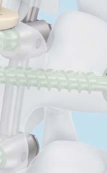
3 XRL SyStem a modular expandable radiolucent vertebral body replacement system. the XRL System provides surgeons the ability to expand the device in situ to reconstruct the anterior column, restore height, and correct the sagittal curvature of the thoraco lumbar spine. x modular construction x 360 implantation x tactile feedback during expansion x most implant options to accommodate a wide range of anatomies Material x peek material offers the benefit of radiolucent imaging, so surgeons can better assess fusion progress and/or tumor recurrence. x modulus of elasticity of peek is approximately between cancellous and cortical bone to aid in stress distribution and load sharing. 2 DePuy Synthes Spine XRL System Surgical Technique


4 implant options Modular Flexible use the modular implant consists of a central body on which two endplates are attached. x central body the octagonal shape permits various approach options x endplates numerous footprints and angles allow the implant to conform to a wide range of patient anatomies x endplate screws Rigidly secures the endplate to the central body Integrated (no assembly required) optimal for procedures where low profile constructs are needed. Self-locking expansion mechanism distracts and locks at 1 mm increments. Open architecture the open central body and endplate design allow generous placement of bone graft. x medium implant cannulation 8.4 mm diameter x Large implant cannulation 13.5 mm diameter DePuy Synthes Spine XRL System Surgical Technique 3


 x anterolateral (Figure 2) x")
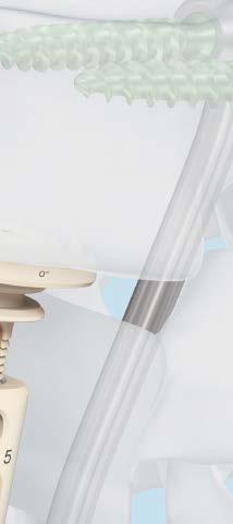
5 XRL SyStem. a modular expandable radiolucent vertebral body replacement system. one instrument provides: x Holding and insertion x distraction/locking x Repositioning of implant, if needed Ratchet and continuous expansion options for tactile feedback x precision control during implant insertion x Scale indicates the amount of distraction achieved Handle repositioning prior to insertion for intraoperative visualization Approach Options x anterior (Figure 1) x anterolateral (Figure 2) x Lateral (Figure 3) x posterolateral (Figure 4) DePuy Synthes Spine XRL System Surgical Technique
6 ao principles in 1958, the ao formulated four basic principles, which have become the guidelines for internal fixation. 1 they are: x anatomic reduction x Stable fixation x preservation of blood supply x early, active mobilization the fundamental aims of fracture treatment in the limbs and fusion of the spine are the same. a specific goal in the spine is returning as much function as possible to the injured neural elements. 2,3 1 müller me, m allgöwer, R Schneider, H Willenegger. manual of internal Fixation. 3rd ed. berlin Heidelberg new york: Springer ibid. 3 m aebi, JS thalgott, and JK Webb. ao asif principles in Spine Surgery. berlin; Springer-Verlag, DePuy Synthes Spine XRL System Surgical Technique 5
7 Indications and Contraindications Indications The DePuy Synthes Spine XRL Device is a vertebral body replacement device intended for use in the thoracolumbar spine (T1 L5) to replace a collapsed, damaged or unstable vertebral body due to tumor or trauma (i.e., fracture). The DePuy Synthes Spine XRL Device is intended to be used with DePuy Synthes supplemental internal fixation systems (USS System including MATRIX TM Pedicle Screw System, PANGEA Pedicle Screw System, and TSLP TM Locking Plate System). The interior of DePuy Synthes Spine XRL Device can be packed with bone (i.e., autograft or allograft). The DePuy Synthes Spine XRL Device is designed to provide anterior spinal column support even in the absence of fusion for a prolonged period. Contraindications 1. Use of the DePuy Synthes Spine XRL Device is contraindicated when there is active systemic infection, infection localized to the site of the proposed implantation, or when the patient has demonstrated allergy or foreign body sensitivity to any of the implant materials. 2. Severe osteoporosis may prevent adequate fixation and thus preclude the use of this or any other orthopaedic implant. 3. Conditions that may place excessive stresses on bone and implants, such as severe obesity or degenerative diseases, are relative contraindications. The decision whether to use these devices in patients with such conditions must be made by the physician, taking into account the risks versus the benefits to the patient. 4. Use of these implants is relatively contraindicated in patients whose activity, mental capacity, mental illness, alcoholism, drug abuse, occupation or lifestyle may interfere with their ability to follow postoperative restrictions, thereby placing undue stresses on the implant during bony healing. This could result in a higher risk of implant failure. Please refer to package insert for the full list of indications, contraindications, warnings and/or precautions. 6 DePuy Synthes Spine XRL System Surgical Technique
8 Preparation 1 Access Various approaches are suitable depending on the affected spinal level involved. The following surgical technique is described using a lateral approach from the left at L1. 2 Perform corpectomy Perform a partial or complete corpectomy as required. Note: Remove the superficial layers of the entire cartilaginous endplates and expose bleeding bone. Excessive removal of subchondral bone may weaken the vertebral endplate. If the entire endplate is removed, subsidence and a loss of segmental stability may occur. DePuy Synthes Spine XRL System Surgical Technique 7


9 insert trial implant the XRL Vertebral body Replacement contains a complete line of central body and endplate trial implants that correspond to each central body and endplate implant. trials are placed into the corpectomy site intraoperatively to determine the appropriate endplate footprint, angle, and central body height. 1 Determine defect Instruments metal tape Gauge * measuring Forceps the metal tape gauge or measuring forceps can be used to measure overall defect. Note: If the corpectomy height is less than 34 mm, then skip to Step 4 and use the integrated trials. *also available 8 DePuy Synthes Spine XRL System Surgical Technique


10 2 Select endplate footprint size and angle 2 1 Instruments XRL medium endplate Footprint trials mm round mm x 24 mm mm x 30 mm XRL Large endplate Footprint trials mm round mm x 33 mm mm x 40 mm the endplate footprint trial can be adjusted to accommodate the desired approach. pull the sleeve (1) and turn the endplate trial to the desired position (2). Release the sleeve to lock the position of the trial. determine the footprint using the endplate footprint trial. the handles of the endplate footprint trials are colorcoded green and blue to match the medium and large sets, respectively. determine the angle using lateral x-ray imaging. DePuy Synthes Spine XRL System Surgical Technique 9
. The trials do not account for the implant spikes (Figure 1); therefore, 1 mm clearance on each end of the trial is required.")


11 Insert Trial Implant 3 Determine central body size The optimal central body height is calculated using endplate trial height which is found on the back of the module lid for reference (See page 29 for cross reference list). The trials do not account for the implant spikes (Figure 1); therefore, 1 mm clearance on each end of the trial is required. 1 Optimal Central Body Height (CBH) = Overall defect Cranial trial endplate height Caudal trial endplate height Clearance for spikes 1mm Example for 46 mm defect with a 5 cranial endplate and 10 caudal endplate: CBH = 46 mm 6.5 mm 8.5 mm 2 mm CBH = 29 mm Insert the selected trial endplates onto the trial central body. Align the etch lines before pressing the components together. Ensure there is no gap between the endplate and central body trial. Note: The endplate height is independent of the footprint. Warning: The trials are not for implantation and must be removed before insertion of the XRL implant. Total construct angle must not exceed 30 lordosis/ kyphosis. 1mm 6.5 mm XRL WAM The XRL WAM (Wherever Addition Modifier) Mobile Application can be used with the Surgical Technique Guide by the DePuy Synthes Sales Consultant to calculate modular trial construct height, corresponding implant distraction range, and appropriate spreader top. 8.5 mm 1 mm 29 mm 10 DePuy Synthes Spine XRL System Surgical Technique


12 4 Insert trial Instruments XRL Medium Implant Holder XRL Large Implant Holder Using the implant holder, insert the trial into the corpectomy site. Be sure the appropriate endplate is oriented in the cranial/caudal position and the etch lines on the trial are facing anterior. The optimal position for the trial is centered on the vertebral bodies with 1 mm clearance to account for the implant spikes (modular constructs only). Trials must always be securely held while in the wound. Note: Integrated implants do not have tall spikes and therefore the integrated trials are the same height as the corresponding collapsed implant. Change trial central body and endplates as necessary to achieve the optimal height, angle, and footprint. Warning: Do not excessively impact on trial implants and or implant holder. Use light impaction only. DePuy Synthes Spine XRL System Surgical Technique 11

 on the endplate with the a on the endplate assembly fixture (Figure 1).")


13 implant insertion 1 Assemble implant 1 Select implant based on corresponding trial (see pages for trial/ implant list). if an integrated assembly is selected, skip to Step 4. the endplate assembly Fixture is found in the trial endplate module. When assembling the implant, orient the caudal endplate into the endplate assembly fixture spike side down, aligning the a (anterior) on the endplate with the a on the endplate assembly fixture (Figure 1). position the central body with the locking ring facing the direction of the desired approach (Figure 2). attach the caudal endplate first by pressing the endplate onto the octagon until fully seated. Repeat with the cranial endplate. 2 Note: The etch line on the ends of the central body, the graft window, and the locking ring may all be used to indicate the direction of approach. Figure 3 shows the orientation of the etch line with respect to the caudal endplate for each approach option. Shown: Lateral left approach 3 posterior Lateral left anterior 12 DePuy Synthes Spine XRL System Surgical Technique
.")


14 the etch line on the anterior aspect of the endplate ensures that both endplates are in the same direction (lateral left shown in Figure 4). 4 Warning: When pressing on the endplates, ensure the endplate properly seats on the central body. This can be checked visually (Figure 5). If the endplate is not properly seated, there is a risk that it could detach from the central body. Warning: The XRL Device central body should never be implanted without cranial and caudal endplates properly secured with endplate screws. 5 2 Reposition endplates (optional) Instrument XRL endplate Removal tool if necessary, the endplates can be repositioned by manually removing them from the central body, except for the round endplates which are removed using the XRL endplate Removal tool. be sure to perform endplate removal over a sterile table. Warning: Endplates release from central body abruptly. Make sure to have a firm grip on both the central body and the endplate during removal. to remove round endplates, align the tip of the XRL endplate Removal tool with the slot in the endplate. apply a slight, constant pressure and rotate the tool to release the endplate. DePuy Synthes Spine XRL System Surgical Technique 13


15 implant insertion 3 Attach endplate screws Instruments XRL medium endplate Screwdriver tip XRL Large endplate Screwdriver tip XRL medium torque Limiting Handle XRL Large torque Limiting Handle align the endplate screwdriver tip into the open end of the torque limiting handle. torque limiting handle press until an audible click is heard. align the tri-lobal feature of the tip and the etchings on the endplate screw. Lightly press the screw onto the screwdriver tip. the screwdriver tip will retain the screw. align the torque limiting handle with the central body to prevent cross threading. While gripping the large end of the torque limiting handle, rotate the torque limiting handle clockwise to advance the screw through the caudal endplate and into the central body. tighten until an audible click in the torque handle is heard. Repeat this step to fixate the cranial endplate. Warning: The torque limiting handles are colorcoded green and blue to match the medium and large sets, respectively and may only be used with its corresponding set. Note: Please follow torque limiting handle calibration instructions to ensure proper functionality. 14 DePuy Synthes Spine XRL System Surgical Technique


16 4 Prepare implant Instruments XRL medium Graft packing preparation tamp XRL Large Graft packing preparation tamp prior to implanting, use graft packing tamps to facilitate packing of bone graft into the XRL implant. Graft can be packed through the cannulation in the endplate and graft windows. Warning: Do NOT pack graft into the locking ring. DO NOT use excessive force while packing graft. DO NOT pack graft while implant is loaded onto the spreader. DePuy Synthes Spine XRL System Surgical Technique 15
.")
. Press T-driver release button and pull back on the T-driver (Figure 2).")
 and insert the T-driver (5) by gently pushing and turning the T-driver into the spreader assembly.")
17 Implant Insertion 5 Assemble spreader instrument 1 2 Instruments XRL Spreader XRL Medium Shaft XRL Medium Spreader Tops, with 3, 5, 8, 10, or 15 mm distraction XRL Large Shaft XRL Large Spreader Tops, with 3, 5, 8, 10, or 15 mm distraction XRL Release Tool XRL WAM Assemble the appropriate size spreader top to the XRL Spreader according to the implant central body size selected (See page 29 cross reference list). The spreader tops are designed to prevent over-distracting the implant. Note: The underside of the built-in lid of the graphic case shows Spreader Top and its corresponding implant selection. While holding the spreader with the shaft in the horizontal position, set ratchet lever to the OFF position (Figure 1). Press T-driver release button and pull back on the T-driver (Figure 2). Release the button to set T-driver in the open position (Figure 3). T-driver should not be fully removed during this operation. Insert the selected spreader top into the spreader shaft (4) and insert the T-driver (5) by gently pushing and turning the T-driver into the spreader assembly. 16 DePuy Synthes Spine XRL System Surgical Technique


.")
. do not force spreader top onto implant.")
.")
18 check functionality of spreader top by rotating t-driver. if properly assembled, spreader top should translate during t-driver rotation, and t-driver will remain retained by the spreader assembly Secure implant to spreader 1 2 Instruments XRL Spreader to load the implant, fully collapse the spreader top and set the ratchet lever to the off position (Figure 1). With the locking ring facing the instrument, slide the spreader top into the slots below the cranial endplate (Figure 2). do not force spreader top onto implant. Set the ratchet lever on (Figure 3) and slightly turn the t-driver clockwise until the spreader shaft engages the notch on the implant for a secure hold (Figure 4). Verify the implant is secured over the sterile field. 3 4 Set the scale to zero (Figure 5). completely insert the release tool through the XRL spreader and into the locking ring (Figure 6). 5 6 DePuy Synthes Spine XRL System Surgical Technique 17
. With one hand gripping the spreader shaft, pull back on retaining collar and rotate the spreader handle to the desired position (2,3).")


19 Implant Insertion 7 Insert implant 2 Instrument XRL Spreader Prior to inserting the implant the spreader handle can be rotated at 90 increments to aid in visualization. Set ratchet lever to OFF position (1). With one hand gripping the spreader shaft, pull back on retaining collar and rotate the spreader handle to the desired position (2,3). Release retaining collar. Verify that the spreader handle is locked into position. Reset scale to zero Warning: Do not adjust spreader handle when ratchet lever is set to ON. This will result in premature distraction of the implant. Do not insert the implant into corpectomy until spreader handle is locked into desired position. Guide and position the implant with the spreader. Slight distraction of the vertebral bodies may be necessary to ease insertion. The optimal position for the implant is in the center of the vertebral body endplate. Maintain space around the endplate of the implant to allow peripheral bony fusion. Warning: Do not impact on spreader. Do not manipulate implant unless both the slot and notch are engaged. 18 DePuy Synthes Spine XRL System Surgical Technique


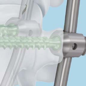
20 Verify the position of the implant using the image intensifier. x tantalum markers and a titanium locking ring is used to determine orientation of the implant x the 1 mm diameter tantalum markers are embedded into the PEEK endplates to provide radiographic markers for intraoperative or postoperative imaging x the anterior and medial/lateral markers are located approximately 1 mm from the edges of the implant. The posterior marker is located 1 mm from the edge of the round implant, and 2 mm from the edge of the anatomically shaped end-plates. The cranial/caudal locations of the markers are 2 mm from the end of the pyramidal teeth. 1 mm 2 mm DePuy Synthes Spine XRL System Surgical Technique 19
 and expand the")
 and with constant clockwise torque on the T-driver, place the ratchet lever in the OFF position (Figure 4a).")
21 Implant Insertion 8 Distract and check position A) Rachet Mode B) Continuous Mode 1a 1b Instrument XRL Spreader The spreader allows for expansion in both a ratchet mode and continuous mode. Option A: Ratchet Mode For ratchet mode, ensure the release tool is engaged and the ratchet lever is set to the ON position, then turn the spreader T-driver clockwise (Figure 2a) and expand the implant until the desired amount of distraction is achieved. Once the implant has been distracted, fully remove the release tool, (Figure 3a) and with constant clockwise torque on the T-driver, place the ratchet lever in the OFF position (Figure 4a). 2a 3a 2b 3b Option B: Continuous Mode For continuous mode, ensure the release tool is engaged and the ratchet lever is set to the OFF position, then turn the spreader T-driver clockwise and expand the implant until the desired amount of distraction is achieved. With constant clockwise torque on the T-driver, set the ratchet lever to the ON position (Figure 3b). Once the implant has been distracted, fully remove the release tool, (Figure 4b) and with constant clockwise torque on the T-driver, place the ratchet lever in the OFF position (Figure 5b). Note: The release tool may also be set in the resting position instead of being fully removed from the spreader. Pull up on the release tool until it travels ~15 mm and it will be retained by the spreader in the resting position. 4a 4b 5b 20 DePuy Synthes Spine XRL System Surgical Technique
. 1 2 2.")
, re-expand the spreader and distract slightly to close the locking")
.")

, reposition as necessary to ensure full endplate surface contact.")


22 1. before removing the spreader, verify the locking ring is properly closed by closing the spreader and visually inspecting the slot through the spreader top (Figure 1) When the slot is approximately 1 mm (Figure 2), the implant is locked and secured. 3. if the slot is larger (Figure 3), re-expand the spreader and distract slightly to close the locking ring. If implant remains unlocked, follow step 9 (Reposition Implant). If the locking ring is not visible, inspect lock after spreader is removed (See step 10). 3 4 Close the spreader by setting the ratchet lever to OFF and turning the T-driver counterclockwise. When spreader top is fully closed, the spreader can be removed. Visually inspect implant/vertebral body interface for gaps to prevent point loading. If a gap is found (Figure 4), reposition as necessary to ensure full endplate surface contact. Verify the position of the implant using the image intensifier. Figure 5 and 6 show a fully undistracted and a fully distracted implant respectively. The stop pin can be used to approximate the amount of distraction available. When the stop pin is within 1 mm of the locking ring, the implant is fully distracted. 5 6 Do not reuse XRL Implants. Warning: Do not reposition spreader handle during or after distraction. locking ring Distraction of the implant is only permitted with the XRL Instrument Set. stop pin DePuy Synthes Spine XRL System Surgical Technique 21


.")
. Fully insert the release tool (Figure 6).")


23 implant insertion 9 Reposition implant (optional) 1 2 Instrument XRL Spreader to reposition the implant, fully collapse the spreader top and set the ratchet lever to the off position (Figure 1). 3 4 be sure the release tool is removed or disengaged and set to the resting position per alternate technique (Figure 2). Slide the spreader top into the slots below the cranial endplate (Figure 3). Set ratchet lever to on (Figure 4) and turn the t-driver clockwise until spreader engages the notch on the implant for a secure hold (Figure 5). Fully insert the release tool (Figure 6). With constant clockwise torque on the t-driver, set the ratchet lever to off position and compress the implant by turning the t-driver counterclockwise. Reposition the implant to the desired location and follow step 8 to re-distract implant. 5 6 Warning: Do not impact on the XRL Endplates when repositioning the implant. The T-driver may release abruptly. Be sure to apply constant clockwise torque when switching the ratchet lever to OFF. Repositioning of the implant is only permitted with the XRL Instrument Set. 22 DePuy Synthes Spine XRL System Surgical Technique


24 10 Verify lock 1 When the implant is in its final position, verify the locking ring on the central body is closed. When the slot is approximately 1 mm (Figure 1), the implant is locked and secured. locked if the slot is larger (Figure 2), re-engage the implant with the spreader, with the ratchet lever in the off position, and with the release tool fully removed, distract the implant slightly to close the locking ring. if implant remains unlocked, repeat step 9 and verify locking ring is closed. Warning: Locking ring must be properly closed to ensure final implant height is maintained. 2 unlocked DePuy Synthes Spine XRL System Surgical Technique 23

25 Supplemental Fixation 1 Apply bone material Instruments XRL Medium Graft Packing Tamp XRL Large Graft Packing Tamp XRL Medium Graft Packing Preparation Tamp XRL Large Graft Packing Preparation Tamp In situ graft packing must not occur until final implant position is achieved, as additional bone graft may obstruct repositioning of the implant. Before packing additional bone graft in or around the cage, use AP and lateral radiographs to verify the position of the implant in relation to the vertebral bodies using the tantalum markers and locking ring for references. The graft packing tamp has 2 different ends to fit the corresponding window of the expanded central body. The preparation tamp has an angled end that can be used to gain compression on graft that is not accessible with the graft packing tamp. Note: Graft packing tamp will not fit inside the window of integrated implant #1, however can still be used to tamp graft material. Warning: Do not use excessive force while packing graft. 24 DePuy Synthes Spine XRL System Surgical Technique

26 2 Apply supplemental fixation For spinal stability and to maintain adequate compression on the construct, the XRL System is indicated for use with supplemental fixation. Warning: Take care when applying supplemental fixation that the superior and inferior vertebral body endplates remain fixed. Manipulation of vertebral bodies may cause the XRL Implant to shift in the wound possibly resulting in a need to reposition the implant. DePuy Synthes Spine XRL System Surgical Technique 25


 to 145 mm (fully")


 to 37 mm")

27 implants Modular XRL Implants XRL medium x 21 mm central body diameter x endplate footprint options: 21 mm round 21 mm x 24 mm 26 mm x 30 mm x construct heights range from 32 mm (fully compressed) to 142 mm (fully expanded) x Various lordotic/kyphotic angulation options XRL Large x 27 mm body diameter x endplate footprint options: 27 mm round 28 mm x 33 mm 30 mm x 40 mm x construct heights range from 33 mm (fully compressed) to 145 mm (fully expanded) Various lordotic angulation options Integrated XRL Implants XRL medium x 21 mm central body diameter x 21 mm endplate footprint x Heights range from 22 mm (fully compressed) to 36 mm (fully expanded) x 0 parallel endplates XRL Large x 27 mm body diameter x 27 mm endplate footprint x Heights range from 23 mm (fully compressed) to 37 mm (fully expanded) x 0 parallel endplates note: all XRL implants are supplied sterile 26 DePuy Synthes Spine XRL System Surgical Technique

.")

28 instruments XRL trial implants the XRL Vertebral body Replacement contains a complete line of central body and endplate trials that correspond to each central body and endplate implant. trials are placed into the corpectomy site intraoperatively to determine the appropriate implant footprint, lordotic angle and central body height. Use the central body and endplate trials to determine the largest implant size (integrated or modular) that will fit the measured corpectomy site. trials may be secured and lowered into corpectomy defect using the implant holder. allow 1 mm clearance on each end for the tall spikes on the endplates (modular only). Medium Trials (green) Medium Trial Endplates (green) part number description part number trial implants central bodies Size corresponding (mm) implants integrated height, S integrated height, S integrated height, S heig ht S height S height S height S height S height S height S height S height S height S height S height S part number description corresponding (mm) implants Round, S Round, S Round, S Round, S x 24, S x 24, S x 24, S x 24, S x 24, S x 24, S x 30, S x 30, S x 30, S x 30, S x 30, S x 30, S DePuy Synthes Spine XRL System Surgical Technique 27


29 instruments XRL trial implants Large Trials (blue) Large Trial Endplates (blue) part number description part number trial implants central bodies Size corresponding (mm) implants integrated height, S integrated height, S integrated height, S height S height S height S height S height S height S height S height S height S height S height S height S part number description corresponding (mm) implants round, S round, S round, S round, S round, S x 33, S x 33, S x 33, S x 33, S x 33, S x 40, S x 40, S x 40, S x 40, S x 40, S 28 DePuy Synthes Spine XRL System Surgical Technique
30 Cross Reference List XRL Medium XRL Large Cranial Endplate Angle Cranial Endplate Angle Endplate Footprint Endplate Footprint mm Endplate 27 mm Endplate 21 mm x 24 mm Height 28 mm x 33 mm Height 26 mm x 30 mm (mm) 30 mm x 40 mm (mm) Central Body Central Body Distraction Spreader Number Height (mm) Range (mm) Top 1* 22* 3 1 2* 24* 5 2 3* 28* Central Body Central Body Distraction Spreader Number Height (mm) Range (mm) top 1* 23* 3 1 2* 25* 5 2 3* 29* Caudal Endplate Angle Caudal Endplate Angle Endplate Footprint Endplate Footprint mm Endplate 27 mm Endplate 21 mm x 24 mm Height 28 mm x 33 mm Height 26 mm x 30 mm (mm) 30 mm x 40 mm (mm) 1mm Cranial Central Body Caudal 1mm * Integrated Assembly, no endplates needed DePuy Synthes Spine XRL System Surgical Technique 29
 Ratchet Lever a ratchet lever on the instrument handle allows for the manipulations of the XRL implant.")
31 instruments XRL Spreader For implanting, distracting, and compressing (repositioning the implant) Ratchet Lever a ratchet lever on the instrument handle allows for the manipulations of the XRL implant. Note: Release tool must be engaged with locking ring for implant manipulation. T-driver Release allows the t-driver to be disengaged/removed from the spreader Ratchet mode on allows expansion of the implant continuous mode off allows tactile expansion or compression of the implant Shaft Release allows the spreader shaft to be removed from the spreader Retaining Collar allows 90 rotation of the spreader handle prior to implantation Scale Used to determine the achieved amount of expansion T-driver allows expansion or compression of the implant clockwise = expansion counterclockwise = compression 30 DePuy Synthes XRL System Technique Guide


32 instruments metal tape Gauge XRL medium Shaft XRL Large Shaft (shown) Release tool enables implant repositioning Spreader tops medium available in six distraction ranges, dependent on the central body implant with 3 mm distraction with 5 mm distraction with 8 mm distraction with 10 mm distraction with 15 mm distraction with 5 mm distraction Large with 3 mm distraction with 5 mm distraction with 8 mm distraction with 10 mm distraction with 15 mm distraction with 5 mm distraction XRL endplate Screwdriver tips medium Large DePuy Synthes Spine XRL System Surgical Technique 31


33 instruments XRL endplate Removal tool allows removal of round endplates from the central body XRL torque Limiting Handles medium (shown) Large endplate Footprint trials medium 21 mm round medium 21 mm X 24 mm medium 26 mm X 30 mm Large 27 mm Round Large 28 mm X 33 mm Large 30 mm X 40 mm Graft packing tamps medium tamp medium preparation tamp Large tamp Large preparation tamp implant Holder medium implant Holder (shown) Large implant Holder For inserting the implant trials 32 DePuy Synthes XRL System Technique Guide
34 SpReadeR disassembly DePuy Synthes Spine XRL System Surgical Technique 33


35 XRL medium implant and instrument Set ( ) Carry Case and Graphic Case carry case, for XRL medium implants Graphic case, for XRL medium instruments Instruments metal tape Gauge XRL Spreader XRL medium Shaft XRL Release tool XRL medium Spreader top with 3 mm distraction with 5 mm distraction with 8 mm distraction with 10 mm distraction with 15 mm distraction with 5 mm distraction XRL medium endplate Screwdriver tip XRL endplate Removal tool XRL medium torque Limiting Handle XRL medium endplate Footprint trial, 21 mm round XRL medium endplate Footprint trial, 21 mm x 24 mm XRL medium endplate Footprint trial, 26 mm x 30 mm XRL medium Graft packing tamp XRL medium Graft packing preparation tamp XRL medium implant Holder 34 DePuy Synthes Spine XRL System Surgical Technique
36 XRL Medium Implant and Instrument Set ( ) Implants XRL Medium Implant, Integrated, 0, sterile Height S 22 mm 25 mm S 24 mm 29 mm S 28 mm 36 mm XRL Medium Central Body, sterile Height S 22 mm 27 mm S 25 mm 33 mm S 29 mm 39 mm S 33 mm 43 mm S 37 mm 52 mm S 44 mm 59 mm S 51 mm 66 mm S 62 mm 77 mm Also Available S S S S XRL Medium Central Body, 73 mm 88 mm height, sterile XRL Medium Central Body, 84 mm 99 mm height, sterile XRL Medium Central Body, 95 mm 110 mm height, sterile XRL Medium Central Body, 106 mm 121 mm height, sterile XRL Medium Endplate, 21 mm round, sterile S S S S 15 XRL Medium Endplate, 21 mm x 24 mm, sterile S S S S S S 15 XRL Medium Endplates, 26 mm x 30 mm, sterile S S S S S S S XRL Medium Endplate Screws, sterile DePuy Synthes Spine XRL System Surgical Technique 33


37 XRL medium trial instrument Set ( ) Graphic Case Graphic case, for XRL medium trials Trials XRL medium trial, integrated, 0 Height mm 25 mm mm 29 mm mm 36 mm XRL medium trial, central body Height mm 27 mm mm 33 mm mm 39 mm mm 43 mm mm 52 mm mm 59 mm mm 66 mm mm 77 mm Also Available XRL medium trial, central body, 73 mm 88 mm height XRL medium trial, central body, 84 mm 99 mm height XRL medium trial, central body, 95 mm 110 mm height XRL medium trial, central body, 106 mm 121 mm height XRL medium trial, endplate, 21 mm round XRL medium trial endplate, 21 mm x 24 mm XRL medium trial endplate, 26 mm x 30 mm DePuy Synthes XRL System Technique Guide


38 XRL LaRGe implant and instrument Set ( ) Carry Case and Graphic Case carry case, for XRL Large implants Graphic case, for XRL Large instrument Instruments metal tape Gauge XRL Spreader XRL Large Shaft XRL Large Spreader top with 3 mm distraction with 5 mm distraction with 8 mm distraction with 10 mm distraction with 15 mm distraction with 5 mm distraction XRL Release tool XRL Large endplate Screwdriver tip XRL endplate Removal tool XRL Large torque Limiting Handle XRL Large endplate Footprint trial, 27 mm round XRL Large endplate Footprint trial, 28 mm x 33 mm XRL Large endplate Footprint trial, 30 mm x 40 mm XRL Large Graft packing tamp XRL Large Graft packing preparation tamp XRL Large implant Holder DePuy Synthes Spine XRL System Surgical Technique 37
39 XRL large implant and instrument set ( ) Implants XRL Large Implant, Integrated, 0, sterile Height S 23 mm 26 mm S 25 mm 30 mm S 29 mm 37 mm XRL Large Central Body, sterile Height S 22 mm 27 mm S 25 mm 33 mm S 29 mm 39 mm S 33 mm 43 mm S 37 mm 52 mm S 44 mm 59 mm S 51 mm 66 mm S 62 mm 77 mm Also Available S S S S XRL Large Central Body, 73 mm 88 mm height, sterile XRL Large Central Body, 84 mm 99 mm height, sterile XRL Large Central Body, 95 mm 110 mm height, sterile XRL Large Central Body, 106 mm 121 mm height, sterile XRL Large Endplates, 27 mm round, sterile S S S S S 20 XRL Large Endplates, 28 mm x 33 mm, sterile S S S S S 20 XRL Large Endplates, 30 mm x 40 mm, sterile S S S S S S XRL Large Endplate Screws, sterile 33 DePuy Synthes XRL System Technique Guide


40 XRL LaRGe trial instrument Set ( ) Graphic case, for XRL Large trials Trials XRL Large trial, integrated, 0 Height mm 26 mm mm 30 mm mm 37 mm XRL Large trial, central body Height mm 27 mm mm 33 mm mm 39 mm mm 43 mm mm 52 mm mm 59 mm mm 66 mm mm 77 mm XRL Large trial, endplate, 27 mm round XRL Large trial, endplate, 28 mm x 33 mm Also Available XRL Large trial, central body, 73 mm 88 mm height XRL Large trial, central body, 84 mm 99 mm height XRL Large trial, central body, 95 mm 110 mm height XRL Large trial, central body, 106 mm 121 mm height XRL Large trial, endplate, 30 mm x 40 mm DePuy Synthes Spine XRL System Surgical Technique 39
41 CAUTION: USA Law restricts these devices to sale by or on the order of a physician. Manufactured or distributed in the United States by: Synthes (USA) 1302 Wrights Lane East West Chester, PA Telephone: (610) To order: (800) Legal manufacturer in Canada: Synthes (Canada) Ltd Meadowpine Boulevard Mississauga, Ontario L5N 6P9 Telephone: (905) To order: (800) Fax: (905) DePuy Spine, Inc., a division of DOI All rights reserved. J11184-C 3/14
XRL A modular expandable radiolucent vertebral body replacement system
 XRL A modular expandable radiolucent vertebral body replacement system This publication is not intended for distribution in the USA. SURGICAL TECHNIQUE Table of Contents Introduction XRL 2 AO Spine Principles
Thoracolumbar Spine Locking Plate (TSLP) System. A low-profile plating system for anterior stabilization of the thoracic and lumbar spine.
 System. A low-profile plating system for anterior stabilization of the thoracic and lumbar spine.") Thoracolumbar Spine Locking Plate (TSLP) System. A low-profile plating system for anterior stabilization of the thoracic and lumbar spine. Technique Guide Instruments and implants approved by the AO Foundation
Thoracolumbar Spine Locking Plate (TSLP) System. A low-profile plating system for anterior stabilization of the thoracic and lumbar spine. Technique Guide Instruments and implants approved by the AO Foundation
Synex System TECHNIQUE GUIDE. An expandable vertebral body replacement device
 Synex System TECHNIQUE GUIDE An expandable vertebral body replacement device Original Instruments and Implants of the Association for the Study of Internal Fixation AO ASIF Synex System Overview The Synex
Thoracolumbar Anterior Compression (TAC) System. Allows distraction, compression, and lateral fixation of the lower thoracic and lumbar spine.
 System. Allows distraction, compression, and lateral fixation of the lower thoracic and lumbar spine.") Thoracolumbar Anterior Compression (TAC) System. Allows distraction, compression, and lateral fixation of the lower thoracic and lumbar spine. Technique Guide Instruments and implants approved by the AO
Thoracolumbar Anterior Compression (TAC) System. Allows distraction, compression, and lateral fixation of the lower thoracic and lumbar spine. Technique Guide Instruments and implants approved by the AO
ECD EXPANDABLE CORPECTOMY DEVICE Continuously Expandable Vertebral Body Replacement for Tumour Cases
 ECD EXPANDABLE CORPECTOMY DEVICE Continuously Expandable Vertebral Body Replacement for Tumour Cases Instruments and implants approved by the AO Foundation. This publication is not intended for distribution
Technique Guide. T-PAL. Transforaminal posterior atraumatic lumbar spacer system.
 Technique Guide T-PAL. Transforaminal posterior atraumatic lumbar spacer system. Table of Contents Introduction T-PAL 2 AO Principles 4 Indications and Contraindications 5 Surgical Technique Preparation
Technique Guide. ECD Expandable Corpectomy Device. Continuously Expandable Vertebral Body Replacement for Tumour Cases.
 Technique Guide ECD Expandable Corpectomy Device. Continuously Expandable Vertebral Body Replacement for Tumour Cases. Table of Contents Introduction Overview 2 AO ASIF Principles 4 Indications and Contraindications
Trephine System. Principle-based anterior lumbar interbody fusion.
 Trephine System. Principle-based anterior lumbar interbody fusion. Technique Guide Instruments and implants approved by the AO Foundation Table of Contents Introduction Trephine System 2 AO Principles
CSLP Quick Lock Screws. Preassembled expansionhead screw and locking screw for use with Cervical Spine Locking Plates (CSLP).
.") CSLP Quick Lock Screws. Preassembled expansionhead screw and locking screw for use with Cervical Spine Locking Plates (CSLP). Technique Guide Instruments and implants approved by the AO Foundation Table
CSLP Quick Lock Screws. Preassembled expansionhead screw and locking screw for use with Cervical Spine Locking Plates (CSLP). Technique Guide Instruments and implants approved by the AO Foundation Table
Luminary ALIF. Disc preparation and implant insertion instruments.
 Luminary ALIF. Disc preparation and implant insertion instruments. Technique Guide Instruments and implants approved by the AO Foundation Table of Contents Introduction Luminary ALIF 2 AO Principles 4
USS Variable Axis Screw (VAS) System. For posterior fixation of the lumbar spine.
 System. For posterior fixation of the lumbar spine.") USS Variable Axis Screw (VAS) System. For posterior fixation of the lumbar spine. Technique Guide Instruments and implants approved by the AO Foundation Table of Contents Introduction USS Variable Axis
USS Variable Axis Screw (VAS) System. For posterior fixation of the lumbar spine. Technique Guide Instruments and implants approved by the AO Foundation Table of Contents Introduction USS Variable Axis
The vertebral body replacement with ratchet mechanism. Synex. Surgical Technique
 The vertebral body replacement with ratchet mechanism Synex Surgical Technique Image intensifier control This description alone does not provide sufficient background for direct use of DePuy Synthes products.
Technique Guide. 3.5 mm LCP Low Bend Medial Distal Tibia Plates. Part of the Synthes locking compression plate (LCP) system.
 system.") Technique Guide 3.5 mm LCP Low Bend Medial Distal Tibia Plates. Part of the Synthes locking compression plate (LCP) system. Table of Contents Introduction 3.5 mm LCP Low Bend Medial Distal Tibia Plates
Technique Guide 3.5 mm LCP Low Bend Medial Distal Tibia Plates. Part of the Synthes locking compression plate (LCP) system. Table of Contents Introduction 3.5 mm LCP Low Bend Medial Distal Tibia Plates
VECTRA-T SURGICAL TECHNIQUE. The Translational Anterior Cervical Palate System. This publication is not intended for distribution in the USA.
 VECTRA-T The Translational Anterior Cervical Palate System This publication is not intended for distribution in the USA. SURGICAL TECHNIQUE Image intensifier control This description alone does not provide
SYNEX The vertebral body replacement with ratchet mechanism
 SYNEX The vertebral body replacement with ratchet mechanism Instruments and implants approved by the AO Foundation. This publication is not intended for distribution in the USA. SURGICAL TECHNIQUE Image
TSLP Thoracolumbar Spine Locking Plate
 Anterior thoracolumbar spine locking plate TSLP Thoracolumbar Spine Locking Plate Surgical Technique Image intensifier control This description alone does not provide sufficient background for direct use
T-PAL Spacer System. Transforaminal posterior atraumatic lumbar spacer system.
 T-PAL Spacer System. Transforaminal posterior atraumatic lumbar spacer system. One instrument, one technique Accommodates both open and MIS approaches A PEEK implant that works with patient anatomy Streamlined
Surgical technique. synex. The vertebral body replacement with ratchet mechanism.
 Surgical technique synex. The vertebral body replacement with ratchet mechanism. Table of contents Indications and contraindications 2 Implants 3 Surgical technique 4 Cleaning of instruments 10 Optional
Low Bend Distal Tibia Plates
 Part of the DePuy Synthes Locking Compression Plate (LCP ) System 3.5 mm LCP Low Bend Medial Distal Tibia Plates Surgical Technique Table of Contents Introduction 3.5 mm LCP Low Bend Medial Distal Tibia
HawkeyeTM Peek. surgical technique
 HawkeyeTM Peek surgical technique Introduction The ChoiceSpine HAWKEYE Vertebral Body Replacement (VBR) System is intended for use in the thoracolumbar spine (T1 - L5) to replace a collapsed, damaged,
Zero-P Instruments and Implants. Zero-profile anterior cervical interbody fusion (ACIF) device.
 device.") Zero-P Instruments and Implants. Zero-profile anterior cervical interbody fusion (ACIF) device. Technique Guide Instruments and implants approved by the AO Foundation Table of Contents Introduction Zero-P
Zero-P Instruments and Implants. Zero-profile anterior cervical interbody fusion (ACIF) device. Technique Guide Instruments and implants approved by the AO Foundation Table of Contents Introduction Zero-P
VLIFT System Overview. Vertebral Body Replacement System
 VLIFT System Overview Vertebral Body Replacement System VLIFT System System Description The VLIFT Vertebral Body Replacement System consists of a Distractible In Situ (DIS) implant, which enables the surgeon
TELEFIX SURGICAL TECHNIQUE. Implant system for the anterior stabilization of the thoracolumbar spine
 TELEFIX Implant system for the anterior stabilization of the thoracolumbar spine Instruments and implants approved by the AO Foundation. This publication is not intended for distribution in the USA. SURGICAL
3.5 mm LCP Extra-articular Distal Humerus Plate
 Part of the DePuy Synthes Locking Compression Plate (LCP ) System 3.5 mm LCP Extra-articular Distal Humerus Plate Surgical Technique Table of Contents Introduction 3.5 mm LCP Extra-articular Distal Humerus
GIZA Surgical Technique
 GIZA Surgical Technique Vertebral Body Replacement System Manufactured by Titanium alloy material provides mechanical integrity during insertion and distraction, x-ray visibility, and biocompatibility*
SYNCAGE EVOLUTION. This publication is not intended for distribution in the USA. SURGICAL TECHNIQUE
 SYNCAGE EVOLUTION This publication is not intended for distribution in the USA. SURGICAL TECHNIQUE Image intensifier control Warning This description alone does not provide sufficient background for direct
The Versatile Polyaxial Solution for the Universal Spine Systems. USS II Polyaxial. Surgical Technique
 The Versatile Polyaxial Solution for the Universal Spine Systems USS II Polyaxial Surgical Technique Image intensifier control This description alone does not provide sufficient background for direct use
Oracle Spacer. A PEEK spacer for lateral lumbar interbody fusion.
 Oracle Spacer. A PEEK spacer for lateral lumbar interbody fusion. Anatomic shape Self-distracting nose Large central canal Instruments and implants approved by the AO Foundation Oracle Spacer The Oracle
Technique Guide. 3.5 mm LCP Olecranon Plates. Part of the Synthes locking compression plate (LCP) system.
 system.") Technique Guide 3.5 mm LCP Olecranon Plates. Part of the Synthes locking compression plate (LCP) system. Table of Contents Introduction 3.5 mm LCP Olecranon Plates 2 AO Principles 3 Indications 3 Clinical
Technique Guide 3.5 mm LCP Olecranon Plates. Part of the Synthes locking compression plate (LCP) system. Table of Contents Introduction 3.5 mm LCP Olecranon Plates 2 AO Principles 3 Indications 3 Clinical
Occipital Cervical Fusion System. Implants and instruments designed to optimize fixation to the occiput.
 Occipital Cervical Fusion System. Implants and instruments designed to optimize fixation to the occiput. Technique Guide and implants approved by the AO Foundation Table of Contents Introduction Occipital
C-THRU Anterior Spinal System
 C-THRU Anterior Spinal System Surgical Technique Manufactured From Contents Introduction... Page 1 Design Features... Page 2 Instruments... Page 3 Surgical Technique... Page 4 Product Information... Page
Technique Guide. ArcoFix. Anterior-only reduction plate.
 Technique Guide ArcoFix. Anterior-only reduction plate. Table of Contents Introduction ArcoFix 2 AO Principles 4 Indications and Contraindications 5 Surgical Technique Preoperative Planning 6 Insert ArcoFix
Apache Cervical Interbody Fusion Device. Surgical Technique. Page of 13. LC-005 Rev F
 LC-005 Rev F Apache Cervical Interbody Fusion Device Page of 13 Surgical Technique INDICATIONS: When used as an intervertebral body fusion device, the Genesys Spine Interbody Fusion System is indicated
Interbody fusion cage for the transforaminal approach. Travios. Surgical Technique
 Interbody fusion cage for the transforaminal approach Travios Surgical Technique Image intensifier control This description alone does not provide sufficient background for direct use of DePuy Synthes
SYNFIX. LR Stand Alone Spacer. Instruments and implants for stand alone anterior lumbar interbody fusion (ALIF). Technique Guide
. Technique Guide") SYNFIX LR Stand Alone Spacer. Instruments and implants for stand alone anterior lumbar interbody fusion (ALIF). Technique Guide Table of Contents Introduction SYNFIX LR Stand Alone Spacer 2 AO Principles
SYNFIX LR Stand Alone Spacer. Instruments and implants for stand alone anterior lumbar interbody fusion (ALIF). Technique Guide Table of Contents Introduction SYNFIX LR Stand Alone Spacer 2 AO Principles
The CerviFix System. Including the StarLock Components. CerviFix Clamp and Screw. StarLock Clamp and Screw
 The CerviFix System Including the StarLock Components CerviFix Clamp and Screw StarLock Clamp and Screw The CerviFix System The CerviFix System is a comprehensive set of implants, including clamps, screws,
EXACTECH SPINE. Operative Technique. Cervical Spacer System. Surgeon focused. Patient driven. TM
 EXACTECH SPINE Operative Technique Cervical Spacer System Surgeon focused. Patient driven. TM ACAPELLA ONE Acapella One Cervical Spacer System is an anterior cervical discectomy and fusion device with
Alamo C. Cervical Interbody System Surgical Technique. An Alliance Partners Company
 Cervical Interbody System Surgical Technique Table of Contents Indications for Use................................1 Device Description............................... 1 Alamo C Instruments..............................
Solitaire Anterior Spinal System
 Surgical Technique Solitaire Anterior Spinal System Independent Stabilization for the Anterior Column Available in Titanium and Contents Introduction... Page 1 Design Features... Page 2 Instruments...
Technique Guide. 3.5 mm LCP Low Bend Medial Distal Tibia Plate Aiming Instruments. Part of the 3.5 mm LCP Percutaneous Instrument System.
 Technique Guide 3.5 mm LCP Low Bend Medial Distal Tibia Plate Aiming Instruments. Part of the 3.5 mm LCP Percutaneous Instrument System. Table of Contents Introduction 3.5 mm LCP Low Bend Medial Distal
2.4 mm Variable Angle LCP Intercarpal Fusion System. Variable angle locking technology for mediocarpal partial arthrodesis.
 2.4 mm Variable Angle LCP Intercarpal Fusion System. Variable angle locking technology for mediocarpal partial arthrodesis. Technique Guide Instruments and implants approved by the AO Foundation Table
LCP Medial Distal Tibia Plate, without Tab. The Low Profile Anatomic Fixation System with Angular Stability and Optimal Screw Orientation.
 LCP Medial Distal Tibia Plate, without Tab. The Low Profile Anatomic Fixation System with Angular Stability and Optimal Screw Orientation. Technique Guide LCP Small Fragment System Table of Contents Introduction
3.5 mm LCP Olecranon Plates
 Part of the DePuy Synthes Locking Compression Plate (LCP ) System 3.5 mm LCP Olecranon Plates Surgical Technique Table of Contents Introduction 3.5 mm LCP Olecranon Plates 2 AO Principles 3 Indications
Conventus CAGE PH Surgical Techniques
 Conventus CAGE PH Surgical Techniques Conventus Orthopaedics The Conventus CAGE PH (PH Cage) is a permanent implant comprised of an expandable scaffold, made from nitinol and titanium, which is deployed
Spinal Correction FRA Spacer System. For use with the Small Stature FRA Spacer and the FRA Spacer.
 Spinal Correction FRA Spacer System. For use with the Small Stature FRA Spacer and the FRA Spacer. Technique Guide Instruments and implants approved by the AO Foundation Table of Contents Introduction
nva Anterior Lumbar Interbody Fusion System
 nva Anterior Lumbar Interbody Fusion System 1 IMPORTANT INFORMATION FOR PHYSICIANS, SURGEONS, AND/OR STAFF The nv a, nv p, and nv t are an intervertebral body fusion device used in the lumbar spine following
A Fusion of Versatility, Performance and Ease.
 MATRIX Spine System. Degenerative and Deformity. System Guide A Fusion of Versatility, Performance and Ease. Instruments and implants approved by the AO Foundation The MATRIX Spine System is a universal
Cervical Solutions. Optio-C Anterior Cervical Plate. with Allograft/Autograft. Surgical Technique Guide
 Cervical Solutions Optio-C Anterior Cervical Plate with Allograft/Autograft Surgical Technique Guide 2 Optio-C Anterior Cervical Plate with Allograft/Autograft Surgical Technique Guide The Optio-C System
nvt Transforaminal Lumbar Interbody Fusion System
 nvt Transforaminal Lumbar Interbody Fusion System 1 IMPORTANT INFORMATION FOR PHYSICIANS, SURGEONS, AND/OR STAFF The nv a, nv p, and nv t are an intervertebral body fusion device used in the lumbar spine
nvp Posterior Lumbar Interbody Fusion System
 nvp Posterior Lumbar Interbody Fusion System 1 IMPORTANT INFORMATION FOR PHYSICIANS, SURGEONS, AND/OR STAFF The nv a, nv p, and nv t are an intervertebral body fusion device used in the lumbar spine following
ARCH Laminoplasty System. Dedicated System for Open-door Laminoplasty.
 ARCH Laminoplasty System. Dedicated System for Open-door Laminoplasty. Surgical Technique This publication is not intended for distribution in the USA. Instruments and implants approved by the AO Foundation.
Technique Guide. ARCH Laminoplasty System. Dedicated System for Open-door Laminoplasty.
 Technique Guide ARCH Laminoplasty System. Dedicated System for Open-door Laminoplasty. Table of Contents Introduction Overview 2 AO ASIF Principles 4 Indications and Contraindications 5 Product Information
Lag Screw Device Intended for symphyseal fracture fixation of the mandible
 Lag Screw Device Intended for symphyseal fracture fixation of the mandible SUrgicaL TecHNiqUe Lag Screw Device Intended for symphyseal fracture fixation of the mandible Simplifies the lag screw fixation
LCP Low Bend Medial Distal Tibia Plates 3.5 mm. Anatomic plates with low profile head for intra- and extraarticular fractures.
 LCP Low Bend Medial Distal Tibia Plates 3.5 mm. Anatomic plates with low profile head for intra- and extraarticular fractures. Surgical Technique This publication is not intended for distribution in the
Cervical Spacer System surgical technique
 Blackhawk TM Cervical Spacer System surgical technique Blackhawk TM The BLACKHAWK Cervical Spacer System is designed to provide biomechanical stabilization as an adjunct to fusion. Spinal fixation should
Technique Guide. 2.4 mm Variable Angle LCP Distal Radius System. For fragment-specific fracture fixation with variable angle locking technology.
 Technique Guide 2.4 mm Variable Angle LCP Distal Radius System. For fragment-specific fracture fixation with variable angle locking technology. Table of Contents Introduction 2.4 mm Variable Angle LCP
low ProfIle neuro PlaTIng system
 low ProfIle neuro PlaTIng system surgical TeChnIque Table of Contents Introduction Low Profile Neuro Cranial Plating System 2 Surgical Technique Technique 5 Product Information Low Profile Neuro Plates
The Implant. (Klappen außen sind nur 192 mm breit!) Ordering information. You start we help with our clearly arranged Starter Kit:
 Ordering information. You start we help with our clearly arranged Starter Kit:") ATHLET PRODUCT INFORMATION The Implant 1 construct = 1 main body + 1 end body (Klappen außen sind nur 192 mm breit!) Latch mechanism for secure connection of the implant components Ordering information
ATHLET PRODUCT INFORMATION The Implant 1 construct = 1 main body + 1 end body (Klappen außen sind nur 192 mm breit!) Latch mechanism for secure connection of the implant components Ordering information
Technique Guide. Insight Retractor. Minimal invasive access system to the posterior thoracolumbar spine.
 Technique Guide Insight Retractor. Minimal invasive access system to the posterior thoracolumbar spine. Table of Contents Introduction Insight Retractor 2 AO Principles 4 Indications and Contraindications
TABLE OF CONTENTS. ShurFit Anterior Cervical Interbody Fusion (ACIF) System Overview 2. Implant Specifications 3. Instrument Features 4
 System Overview 2. Implant Specifications 3. Instrument Features 4") Surgical Technique TABLE OF CONTENTS ShurFit Anterior Cervical Interbody Fusion (ACIF) System Overview 2 Product Highlights 2 Indications 2 Implant Specifications 3 Instrument Features 4 Surgical Technique
Surgical Technique TABLE OF CONTENTS ShurFit Anterior Cervical Interbody Fusion (ACIF) System Overview 2 Product Highlights 2 Indications 2 Implant Specifications 3 Instrument Features 4 Surgical Technique
SynCage-C short. Surgical Technique. This publication is not intended for distribution in the USA.
 SynCage-C short Surgical Technique This publication is not intended for distribution in the USA. Instruments and implants approved by the AO Foundation. Table of contents Implants 2 Indications/contra-indications
BAK/C Cervical Anterior Interbody Fusion System
 Surgical Technique BAK/C Cervical Anterior Interbody Fusion System The Comfortable Choice for Cervical Fusion BAK/C Cervical Surgical Technique 1 The BAK/C Cervical Fusion System is an alternative to conventional
100 Interpace Parkway Parsippany, NJ
 100 Interpace Parkway Parsippany, NJ 07054 www.biometspine.com 800-526-2579 All trademarks are the property of Biomet, Inc. or one of its subsidiaries, unless otherwise indicated. Rx Only. 2009 EBI, LLC.
Technique Guide. Cranial Clamps with Application Instrument. Quick and stable fixation of cranial bone flaps following a craniotomy.
 Technique Guide Cranial Clamps with Application Instrument. Quick and stable fixation of cranial bone flaps following a craniotomy. Table of Contents Introduction Cranial Clamps with Application Instrument
Royal Oak IBFD System Surgical Technique Posterior Lumbar Interbody Fusion (PLIF)
") Royal Oak IBFD System Surgical Technique Posterior Lumbar Interbody Fusion (PLIF) Preoperative Planning Preoperative planning is necessary for the correct selection of lumbar interbody fusion devices.
Royal Oak IBFD System Surgical Technique Posterior Lumbar Interbody Fusion (PLIF) Preoperative Planning Preoperative planning is necessary for the correct selection of lumbar interbody fusion devices.
Advantage ALIF. Keith Shevlin Managing Director
 Advantage ALIF Unit 10, 9-11 Myrtle Street, Crows Nest NSW 2065 Keith Shevlin Managing Director keithshevlin@precisionsurgical.com.au Advantage ALIF Introduction & Indications for Use 1 Surgical Technique
Technique Guide. Zero-P VA. Variable angle zero-profile anterior cervical interbody fusion (ACIF) device.
 device.") Technique Guide Zero-P VA. Variable angle zero-profile anterior cervical interbody fusion (ACIF) device. Image intensifier control Warning This description alone does not provide sufficient background
Technique Guide Zero-P VA. Variable angle zero-profile anterior cervical interbody fusion (ACIF) device. Image intensifier control Warning This description alone does not provide sufficient background
product overview Implant heights range from 8mm-20mm in 2mm increments, with two lordocic angle options of 6 and 12.
 ETHOS A-Spacer PEEK System Surgical Technique Guide Synchronizing Medical Innovation with Global Markets product overview The SyncMedical Ethos PEEK IBF System is an intervertebral body fusion device for
CROSS -FUSE P E E K V B R / I B F SYST E M
 S U R G I C A L T E C H N I Q U E CROSS -FUSE P E E K V B R / I B F SYST E M S U R G I C A L S Y S T E M O V E R V I E W 2 CROSS-FUSE P E E K V B R / I B F S Y S T E M S U R G I C A L T E C H N I Q U E
Alamo T Transforaminal Lumbar Interbody System Surgical Technique
 Transforaminal Lumbar Interbody System Surgical Technique Table of Contents Indications and Device Description.............. 1 Alamo T Implant Features and Instruments...........2 Surgical Technique......................
USS Variable Axis Screw
 USS Variable Axis Screw Polyaxial side-opening pedicle screw Surgical technique Original Instruments and Implants of the Association for the Study of Internal Fixation AO/ASIF USS Variable Axis Screw
Technique Guide. 3.5 mm LCP Periarticular Proximal Humerus Plate. Part of the Synthes locking compression plate (LCP) system.
 system.") Technique Guide 3.5 mm LCP Periarticular Proximal Humerus Plate. Part of the Synthes locking compression plate (LCP) system. Table of Contents Introduction 3.5 mm LCP Proximal Humerus Plate 2 AO Principles
Technique Guide 3.5 mm LCP Periarticular Proximal Humerus Plate. Part of the Synthes locking compression plate (LCP) system. Table of Contents Introduction 3.5 mm LCP Proximal Humerus Plate 2 AO Principles
Imola Lateral IBF System Surgical Technique
 Imola Lateral IBF System Surgical Technique IMOLA CIRCUIT TABLE OF CONTENTS Design Rationale Instructions for Use Surgical Technique 1. Table Mounting 2. Surgical Planning & Targeting 3. Access and Preparation
Table of Contents.
 surgical technique The Ambassador TM Anterior Cervical Plate System is a versatile system of implants and instruments with a variety of sizes to provide optimal anatomic compatibility. The integrated cam
Valencia Pedicle Screw Surgical Technique
 Valencia Pedicle Screw Surgical Technique VALENCIA CIRCUIT TABLE OF CONTENTS Design Rationale Indications for Use Surgical Technique 1. Pedicle Preparation 2. Screw Insertion 3. Rod Placement 4. Locking
Surgical Technique. Apache Anterior Lumbar Interbody Fusion
 Surgical Technique Apache Anterior Lumbar Interbody Fusion 2 Table of Contents Page Preoperative Planning 4 Patient Positioning 4 Disc and Endplate Preparation 4 Distraction/Size Selection 5 Implantation
LUMBAR POSTERIOR MINIMALLY INVASIVE SYSTEM. Surgical Technique
 LUMBAR POSTERIOR MINIMALLY INVASIVE SYSTEM Surgical Technique Joint Spine Sports Med M.U.S.T. Mini Open Surgical Technique Joint Spine Sports Med CAUTION Federal law (USA) restricts this device to sale
SYNFIX EVOLUTION SECURED SPACER SYSTEM
 SYNFIX EVOLUTION SECURED SPACER SYSTEM Instruments and implants for stand-alone anterior lumbar interbody fusion Instruments and implants approved by the AO Foundation. This publication is not intended
FACET WEDGE. Facet joint fixation device.
 FACET WEDGE. Facet joint fixation device. Technique Guide Synthes FACET WEDGE Technique Guide /44 Synthes FACET WEDGE Technique Guide /44 Table of Contents Introduction FACET WEDGE 3 AO Principles 4 Indications
OPERATIVE TECHNIQUE. CONSTRUX Mini PTC. Mini PTC Spacer System
 OPERATIVE TECHNIQUE CONSTRUX Mini PTC Mini PTC Spacer System TABLE OF CONTENTS Introduction 1 Operative Technique 2 Part Numbers 6 Indications For Use 7 INTRODUCTION 1 INTRODUCTION The CONSTRUX Mini PTC
The Locking Calcaneal Plate Instrument and Implant Sets
 Part of the DePuy Synthes Locking Compression Plate (LCP ) System The Locking Calcaneal Plate Instrument and Implant Sets Surgical Technique Table of Contents Introduction Locking Calcaneal Plate 2 AO
designed to advance the treatment of hip fractures.
 designed to advance the treatment of hip fractures. introducing the tfn-advanced proximal femoral nailing system (tfna). the tfna system is a new system designed to solve a wide range of unmet needs for
Technique Guide. TomoFix Osteotomy System. A comprehensive plating system for stable fixation of osteotomies around the knee.
 Technique Guide TomoFix Osteotomy System. A comprehensive plating system for stable fixation of osteotomies around the knee. Table of Contents Introduction TomoFix Osteotomy System 2 AO Principles 4 Indications
Technique Guide. Compact 2.0 LOCK Mandible. The locking system for the mandible.
 Technique Guide Compact 2.0 LOCK Mandible. The locking system for the mandible. Table of Contents Introduction Compact 2.0 LOCK Mandible 2 AO Principles 4 Indications and Contraindications 5 Surgical
M.I.S. MAKE IT SMART IN ONE SYSTEM. Surgical Technique. Hip Knee Spine Navigation
 M.I.S. MAKE IT SMART IN ONE SYSTEM Surgical Technique Hip Knee Spine Navigation M.U.S.T. Mini Open Surgical Technique Hip Knee Spine Navigation 2 C O N T E N T S 1 INTRODUCTION 4 2 SURGICAL TECHNIQUE 5
Long Volar Plates for Diaphyseal-Metaphyseal Radius Fractures LCP. Dia-Meta Volar Distal Radius Plates. Surgical Technique
 Long Volar Plates for Diaphyseal-Metaphyseal Radius Fractures LCP Dia-Meta Volar Distal Radius Plates Surgical Technique Table of Contents Introduction LCP Dia-Meta Volar Distal Radius Plates 2 AO Principles
Cervical Solutions. Optio-C Anterior Cervical PEEK. Interbody System. Surgical Technique Guide
 Cervical Solutions Optio-C Anterior Cervical PEEK Interbody System Surgical Technique Guide 2 Optio-C Anterior Cervical PEEK Interbody System Surgical Technique Guide The Optio-C System provides a zero-profile
3.5 mm LCP Low Bend Medial Distal Tibia Plate Aiming Instruments
 Part of the 3.5 mm LCP 3.5 mm LCP Low Bend Medial Distal Tibia Plate Aiming Instruments Surgical Technique TABLE OF CONTENTS INTRODUCTION 3.5 mm LCP Low Bend Medial Distal Tibia Plate 2 Aiming Instruments
PILLAR AL. Anterior Lumbar Interbody Fusion (ALIF) and Partial Vertebral Body Replacement (pvbr) PEEK Spacer System OPERATIVE TECHNIQUE
 and Partial Vertebral Body Replacement (pvbr) PEEK Spacer System OPERATIVE TECHNIQUE") PILLAR AL PEEK Spacer System Anterior Lumbar Interbody Fusion (ALIF) and Partial Vertebral Body Replacement (pvbr) OPERATIVE TECHNIQUE Table of Contents 1 INTRODUCTION 2 PRE-OPERATIVE TECHNIQUE 3 OPERATIVE
PILLAR AL PEEK Spacer System Anterior Lumbar Interbody Fusion (ALIF) and Partial Vertebral Body Replacement (pvbr) OPERATIVE TECHNIQUE Table of Contents 1 INTRODUCTION 2 PRE-OPERATIVE TECHNIQUE 3 OPERATIVE
MODULAR DESIGN OFFERS FREEDOM OF CHOICE. Surgical Technique
 MODULAR DESIGN OFFERS FREEDOM OF CHOICE Surgical Technique Joint Spine Sports Med MectaLIF Anterior Surgical Technique 2 INDEX 1. INTRODUCTION 4 1.1 Material & Marker 5 2. INDICATIONS 5 3. CONTRAINDICATIONS
3.5 mm LCP Clavicle Hook Plates
 Part of the Synthes Locking Compression Plate (LCP ) System 3.5 mm LCP Clavicle Hook Plates Surgical Technique Table of Contents Introduction 3.5 mm LCP Clavicle Hook Plates 2 AO Principles 4 Indications
Surgical technique. SynCage-C short
 Surgical technique SynCage-C short Table of contents Implants 2 Indications/contra-indications 3 Surgical technique 4 Image intensifier control Warning This description is not sufficient for immediate
2.4 mm LCP Radial Head Plates. Part of the Synthes LCP Distal Radius Plate System.
 2.4 mm LCP Radial Head Plates. Part of the Synthes LCP Distal Radius Plate System. Technique Guide Instruments and Implants approved by the AO Foundation Table of Contents Introduction 2.4 mm LCP Radial
Dual-Opening USS. For deformity correction.
 Dual-Opening USS. For deformity correction. Technique Guide Instruments and implants approved by the AO Foundation Table of Contents Introduction Dual-Opening USS 2 AO Principles 4 Indications 5 Preoperative
Surgical Technique. CONQUEST FN Femoral Neck Fracture System
 Surgical Technique CONQUEST FN Femoral Neck Fracture System Table of Contents Introduction... 3 Indications... 3 Product Overview... 4 Surgical Technique... 5 Patient Positioning... 5 Reduce the Fracture...
Veyron -C Anterior Cervical System Surgical Technique
 Veyron -C Anterior Cervical System Surgical Technique 2 Veyron-C Anterior Cervical System Surgical Technique Veyron-C Anterior Cervical System Surgical Technique Description, Indications & Contraindications...3
3.5 mm Clavicle Hook Plates
 A Single Solution for Lateral Clavicle Fractures and Acromioclavicular Joint Dislocations 3.5 mm Clavicle Hook Plates Surgical Technique Discontinued December 2017 DSUS/TRM/1016/1126(1) Table of Contents
OBSOLETED. LCP Medial Distal Tibia Plate, without Tab. The Low Profile Anatomic Fixation System with Angular Stability and Optimal Screw Orientation.
 LCP Medial Distal Tibia Plate, without Tab. The Low Profile Anatomic Fixation System with Angular Stability and Optimal Screw Orientation. Surgical Technique LCP Small Fragment System This publication