Technique Guide. MATRIX Spine System MIS Instrumentation. The total solution for simple and complex spine pathology.
|
|
|
- Dwight Lionel Sutton
- 6 years ago
- Views:
Transcription


1 Technique Guide MATRIX Spine System MIS Instrumentation. The total solution for simple and complex spine pathology.
2
3 Table of Contents Introduction MATRIX Spine System MIS Instrumentation 2 AO Principles 6 Indications 7 Surgical Technique Preparation 8 Pedicle Preparation 11 Screw Insertion 19 Rod Introduction 28 Rod Reduction and Locking Cap Introduction 43 Compression and Distraction 52 Locking Cap Loosening 56 Retraction Blade Removal 57 Revision / Removal 58 Product Information Implants 59 Instruments 67 Image intensifier control Warning This description alone does not provide sufficient background for direct use of the instrument set. Instruction by a surgeon experienced in handling these instruments is highly recommended. Reprocessing, Care and Maintenance of Synthes Instruments For general guidelines, function control and dismantling of multi-part instruments, please refer to: MATRIX Spine System MIS Instrumentation Technique Guide Synthes 1


4 MATRIX Spine System MIS Instrumentation. The total solution for simple and complex spine pathology. Matrix MIS is an instrument set designed for insertion of cannulated MATRIX pedicle screws and rods through a percutaneous or mini-open muscle sparing approach. Unique dual core / Double lead screw design Fast and controlled insertion Increased pull-out resistance due to optimal bone purchase Safe handling thanks to atraumatic tip and self tapping thread PrimeLock screwdriver screw interlock Toggle free screw insertion Precise and controlled screw placement 2 Synthes MATRIX Spine System MIS Instrumentation Technique Guide


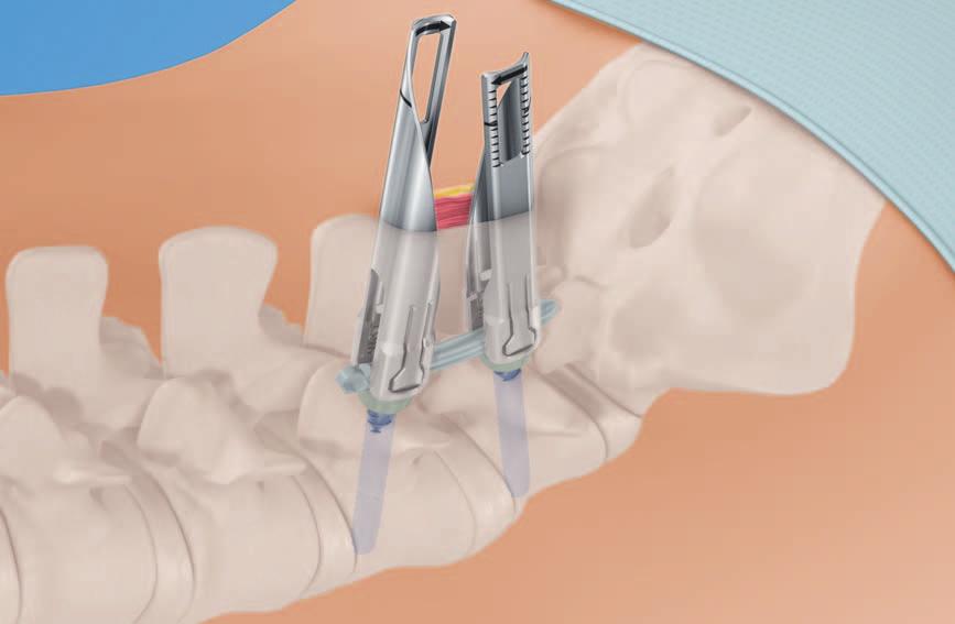
5 Slim retraction blades Minimized muscle trauma Clear access and direct visualization Optimized instruments for treatment of the lumbar-sacral junction Three functions in one instrument Cap guide for rod reduction, locking cap insertion and final tightening Plug in and robust final tightening concept Rod Reduction Cap Insertion Final Tightening MATRIX Spine System MIS Instrumentation Technique Guide Synthes 3


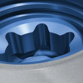
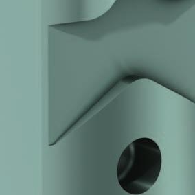
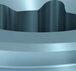
6 MATRIX Spine System MIS Instrumentation. The total solution for simple and complex spine pathology. Implants Preassembled Cannulated Polyaxial Screw Allows 50 of angulation to ease in situ connection to the longitudinal rod Standard Polyaxial head incorporates features to easily mate with retraction blades 1.8 mm cannulation for use over 1.6 mm Kirschner wires Dual core / double lead thread designed to securely anchor the screw in cortical and cancellous bone Threaded T25 Stardrive recess designed to deliver torque effectively 50 Locking Cap Square thread design minimizes cross threading under high reduction loads T25 Stardrive recess designed to reduce the risk of damage at high loads 1-step locking cap allows for complete fixation in one step (polyaxiality and run on rod) Available flat or with guidance MIS Rods 5.5 mm diameter in pure titanium Bullet-nosed to ease navigation through soft tissue Straight and curved options for optimal anatomical adjustment Large rod length portfolio of straight, 100 mm and 200 mm bend radius Radius 100 Radius 200 Straight 4 Synthes MATRIX Spine System MIS Instrumentation Technique Guide

7 Instruments Rod Introduction Instrument Allows rod to pivot with user controlled braking Maintains rod position during cap insertion Easy rod detachment Ergonomic instrumentation Controlled rod insertion Screw-mounted Slim Retraction Blades Slim blades for mini-open and percutaneous approach Enable clear access and direct visualization Provide tissue protection Optimized instruments for treatment of the lumbar-sacral junction Percutaneous retraction blades Mini- open retraction blades MIS Instruments A comprehensive set of MIS specific instruments allows the surgeon to precisely implant the MATRIX MIS System. Dedicated instrument to control the advancement and removal of the Kirschner wire Distraction and compression tool for effective final correction of the vertebral bodies Efficient construct assembly with reduced instrument exchanges MATRIX Spine System MIS Instrumentation Technique Guide Synthes 5
8 AO Principles In 1958, the AO formulated four basic principles, which have become the guidelines for internal fixation. 1 They are: Anatomic reduction Stable internal fixation Preservation of blood supply Early, active mobilization The fundamental aims of fracture treatment in the limbs and fusion of the spine are the same. A specific goal in the spine is returning as much function as possible to the injured neural elements. 2 AO Principles as Applied to the Spine 3 Anatomic alignment Restoration of normal spinal alignment to improve the biomechanics of the spine. Stable internal fixation Stabilization of the spinal segment to promote bony fusion. Preservation of blood supply Creation of an optimal environment for fusion. Early, active mobilization Minimization of damage to the spinal vasculature, dura, and neural elements, which may contribute to pain reduction and improved function for the patient. 1 ME Müller, M Allgöwer, R Schneider, H Willenegger. Manual of Internal Fixation. 3rd, expanded and completely revised ed Berlin, Heidelberg, New York: Springer Ibd. 3 M Aebi, V Arlet, JK Webb (2007). AOSPINE Manual (2 vols.), Stuttgart, New York: Thieme 6 Synthes MATRIX Spine System MIS Instrumentation Technique Guide
9 Indications and Contraindications The MATRIX System is a posterior pedicle screw and hook - fixation system (T1 S2) intended to provide precise and segmental stabilization of the spine in skeletally mature patients. MATRIX MIS is an instrument set designed for insertion of cannulated MATRIX pedicle screws and rods through a percutaneous or mini-open muscle sparing approach. Indications Degenerative disc disease Spondylolisthesis Trauma (i.e. fracture or dislocation) Tumor Stenosis Pseudoarthrosis Failed previous fusion Deformities (i.e. scoliosis, kyphosis and / or lordosis) Contraindications Osteoporosis In fractures and tumors with severe anterior vertebral body disruption, an additional anterior support or column reconstruction is required. MATRIX Spine System MIS Instrumentation Technique Guide Synthes 7

10 Preparation 1 Patient positioning Position the patient on a radiolucent OR table in the prone position. To obtain optimal visualization of the spine, the OR table should have enough clearance available for a fluoroscopic C-arm to rotate freely for AP, oblique and lateral views. Accurate visualization of the anatomic landmarks and fluoroscopic visualization of the pedicles are imperative for using the MATRIX MIS System. In the following sections, the use of AP and lateral fluoroscopy will be described. 8 Synthes MATRIX Spine System MIS Instrumentation Technique Guide
11 2 Approach Option A: Percutaneous approach Instrument Dissector, blunt The percutaneous approach facilitates atraumatic blunt dissection of the muscles through small individual incisions, through which single implants are placed. Using fluoroscopy, locate and mark the lateral borders of each pedicle to receive a screw. These marks indicate where the individual incisions will be made. Each incision should have a sagittal orientation and should be approximately 15 mm in length, depending on patient anatomy and fluoroscopic location of the pedicles. After determining the appropriate locations, make each incision in the skin and the fascia where appropriate. The blunt dissector can be used to facilitate dissection of the tissue prior to subsequent insertion of pedicle preparation instruments. MATRIX Spine System MIS Instrumentation Technique Guide Synthes 9

12 Preparation Option B: Mini-open or Wiltse method Instrument Dissector, blunt The mini-open approach advocates atraumatic blunt dissection of the muscles so that all instruments and implants are introduced through a common incision. A Wiltse or modified Wiltse approach is suggested. 4 Using fluoroscopy, locate and mark the lateral borders of the pedicles. This will indicate where the fascial incisions should be made. As a general guide, the incisions should be made 2 cm 4 cm lateral to the midline. This depends on patient anatomy and actual fluoroscopic location of the pedicles. Lateral or bilateral skin and fascial incisions After determining the surgical trajectory, make an incision in the skin and the fascia of the appropriate size (approximately 30 mm for single-level procedures). Following incision of the fascia, locate the cleavage plane between the multifidus and longissimus muscle groups. Using a Wiltse approach, bluntly dissect between the multifidus and longissimus muscle planes down to the bony anatomy. Careful separation of the muscle planes can yield an avascular dissection. Ensure that adequate dissection is performed to accommodate further instrument and implant placement. The blunt dissector can be used to facilitate dissection of the tissue planes. Midline skin incision Alternatively, a midline skin incision with lateral or bilateral fascial incisions can be applied. 4 LL Wiltse, CW Spencer. New Uses and Refinements of the Paraspinal Approach to the Lumbar Spine. Spine 13(6) (1988): Synthes MATRIX Spine System MIS Instrumentation Technique Guide

13 Pedicle Preparation 1 Perforate cortex of pedicle with Jamshidi needle Working through the incision, locate the pedicles as described in AO ASIF Principles in Spine Surgery. 5 Place the tip of the Jamshidi needle at the entry point of the pedicle and align the Jamshidi needle with the pedicle trajectory. If necessary, reinsert and realign the needle. Advance the Jamshidi needle into the pedicle by tapping lightly with a mallet. Twist the handle one-quarter turn to detach the trocar from the Jamshidi needle while ensuring the Jamshidi needle remains in place. Note: Use fluoroscopy to monitor position of the Jamshidi needle during insertion. 5 Aebi, M, JS Thalgott, and JK Webb. AO ASIF Principles in Spine Surgery. Berlin: Springer-Verlag MATRIX Spine System MIS Instrumentation Technique Guide Synthes 11

. 4 Slide the holding sleeve over the trocar and tighten (2).")

14 Pedicle Preparation Alternative technique Perforate cortex of pedicle with cannulated awl 1 2 Instruments Pedicle Awl 3.8 mm, for Screws 5.0 to 7.0 mm Trocar Holder, for No Trocar, for Cannulated Awl 3 Optional Instrument Pedicle Awl 5.6 mm, for Screws 8.0 to 9.0 mm Assemble cannulated awl Unscrew the knob from the trocar holder and place it on a flat surface. Insert the large end of the trocar and seat it in the knob recess (1). 4 Slide the holding sleeve over the trocar and tighten (2). When the trocar and trocar holding sleeve are assembled, the end of the trocar should be seated in the knob, making it flush with the knob (3). Note: Select the cannulated awl that corresponds to the appropriate screw diameter. Insert the assembled trocar with holding sleeve into the palm handle of the cannulated awl and tighten (4). 12 Synthes MATRIX Spine System MIS Instrumentation Technique Guide


15 Perforate cortex of pedicle with cannulated awl Working through the incision, locate the pedicles as described in AO ASIF Principles in Spine Surgery. 6 Use a cannulated awl with the trocar and trocar holder to perforate the cortex of the pedicle. While maintaining the awl s position within the pedicle, rotate the trocar assembly counter - clockwise to remove it from the end of the awl. Note: Use fluoroscopy to monitor position of the awl during insertion. 6 Aebi, M, JS Thalgott, and JK Webb. AO ASIF Principles in Spine Surgery. Berlin: Springer-Verlag MATRIX Spine System MIS Instrumentation Technique Guide Synthes 13
16 Pedicle Preparation 3 Insert Kirschner wire Instrument Kirschner Wire 1.6 mm without trocar tip, Length 480 mm Warning: Ensure the Kirschner wires remain securely in position throughout the entire duration of the procedure. Note: Monitor the tip of the Kirschner wire under fluoroscopy to ensure it does not penetrate the anterior wall of the vertebral body. Ensure the Kirschner wires do not slip out before the screws are inserted. The Kirschner wires are long enough to be held in place by hand during pedicle preparation and soft tissue dilation. Insert the Kirschner wire into the end of the cannulated awl or Jamshidi needle. Note: Advance the Kirschner wire, guided by fluoroscopy, to the appropriate depth. Kirschner wire etch lines can be used as a depth reference. The Kirschner wire can be advanced manually or with the handle for Kirschner wire (see alternative technique using handle for Kirschner wire). Insert all Kirschner wires as required. 14 Synthes MATRIX Spine System MIS Instrumentation Technique Guide

17 Alternative technique: Using the handle for Kirschner wire Instrument Handle for Kirschner Wire 1.6 mm The handle for Kirschner wire is used to either advance or remove Kirschner wires during the procedure. The arrow on the tool indicates direction of Kirschner wire advancement or removal. To use the handle for Kirschner wire, depress the locking trigger and slip the tool over the Kirschner wire. Release the trigger to locate the tool at a position above the end of the cannulated awl or Jamshidi needle. The distance between the tool and the cannulated awl or Jamshidi needle should be equal to the insertion depth of the Kirschner wire. Lightly mallet the impaction surface to advance the Kirschner wire. Stop impacting when the tool reaches the top of the cannulated awl or Jamshidi needle. Insert all Kirschner wires as required. MATRIX Spine System MIS Instrumentation Technique Guide Synthes 15
18 Pedicle Preparation 4 Pedicle Probe Instrument Pedicle Probe 3.5 mm, cannulated, length 240 mm, for Screws 5.0 to 7.0 mm Optional Instrument Pedicle Probe 5.0 mm, cannulated, length 240 mm, for Screws 8.0 and 9.0 mm While maintaining the position of the Kirschner wire within the pedicle, remove the cannulated awl or Jamshidi needle. Place the tip of the cannulated probe over the end of the Kirschner wire. Probe pedicles as described in AO ASIF Principles in Spine Surgery. 7 Note: To prevent inadvertent advancement of the Kirschner wire, align the trajectory of the probe with the Kirschner wire and monitor the Kirschner wire position using fluoroscopy. 7 Aebi, M, JS Thalgott, and JK Webb. AO ASIF Principles in Spine Surgery. Berlin: Springer-Verlag Synthes MATRIX Spine System MIS Instrumentation Technique Guide

19 5 Tap pedicle (optional) Instruments Tap, cannulated, for Pedicle Screws 5.0 mm with dual core, length 230 /15 mm Tap, cannulated, for Pedicle Screws 6.0 mm with dual core, length 230 /15 mm Tap, cannulated, for Pedicle Screws 7.0 mm with dual core, length 230 /15 mm Tap, cannulated, for Pedicle Screws 8.0 mm with dual core, length 230 /15 mm Tap, cannulated, for Pedicle Screws 9.0 mm with dual core, length 230 /15 mm Protection Sleeve 7.2 / 5.3, for No , violet Protection Sleeve 8.2 / 6.3, for No , blue Protection Sleeve 9.2 / 7.3, for No , green Protection Sleeve 10.2 / 8.3, for No , pink Protection Sleeve 11.2 / 9.3, for No , turquoise T-Handle with Ratchet Wrench, with Hexagonal Coupling 6.0 mm MATRIX Spine System MIS Instrumentation Technique Guide Synthes 17
20 Pedicle Preparation Prepare a pathway for the dual core screws with the cannulated taps by penetrating the pedicle prior to screw insertion. To minimize trauma to surrounding soft tissues, protection sleeves cover the proximal tip of the tap. To lock the protection sleeve onto the cannulated tap shaft, align the arrows and push together. To unlock the protection sleeve, hold the knurled portion of the protection sleeve and advance the tap clockwise. Depth graduations are provided at both ends of the tap to estimate depth measurement for proper implant sizing. Note: To prevent inadvertent advancement of the Kirschner wire, align the trajectory of the tap with the Kirschner wire and monitor the Kirschner wire position using fluoroscopy. Note: To minimize trauma to surrounding soft tissues, protection sleeves to cover proximal tip of the tap must be used. 18 Synthes MATRIX Spine System MIS Instrumentation Technique Guide
 and type (mini-open or percutaneous) must be")
21 Screw Insertion 1 Select retraction blades Instruments Dilator 1.8 /10.0 mm, cannulated, for Guide Wire 1.6 mm Retraction blade, percutaneous Retraction blade, mini-open Optional instruments: Retraction blade, percutaneous, long Retraction blade, mini-open, long The correct length of the retraction blade (standard or long) and type (mini-open or percutaneous) must be determined after the Kirschner wires have been placed and pedicles have been prepared. Insert the 10 mm dilator over the Kirschner wire until the tip reaches the pedicle entry point. To prevent inadvertent advancement of the Kirschner wire while inserting the dilator, monitor the Kirschner wire position using fluoroscopy. Etch markings on the side of the dilator indicate tissue depth. Use the standard retraction blade for approaches up to 80 mm. Use the long retraction blade for any approach greater than 80 mm. 85 mm 115 mm Note: For the mini-open method, a single level construct will utilize only retraction blade, mini-open. For percutaneous method and multilevel constructs, use the retraction blade, percutaneous at all levels. Retraction blades, standard Retraction blades, long MATRIX Spine System MIS Instrumentation Technique Guide Synthes 19


22 Screw Insertion 2a Attach retraction blade to pedicle screw seated in the screw module Choose the appropriate screw diameter and length based on pedicle probe feedback. Press the retraction blade onto the pedicle screw in the screw module until they snap together. Note: To ensure proper fit of pedicle screws, verify the dia meter of the pedicle awl / probe and the selected screw correspond to each other. Note: When using a retraction blade, mini-open pinch the retraction blade while pressing the blade onto the pedicle screw until they snap together. Note: To avoid glove damage, do not hold the retraction blade near the bottom of the deflecting tab. Note: Check by push and pull of the retraction blade / screw construct to ensure a secure attachment. Retraction blade, mini-open Retraction blade, percutaneous 20 Synthes MATRIX Spine System MIS Instrumentation Technique Guide
 while pressing the retraction blade onto the pedicle screw until they snap together.")

23 2b Alternative technique: Freehand attachment of retraction blade To connect a retraction blade, mini-open to the screw, hold the pedicle screw and the retraction blade in opposite hands, and align the slots. Pinch the retraction blade as shown in (1) while pressing the retraction blade onto the pedicle screw until they snap together. 1 To connect a retraction blade, percutaneous to the screw, snap the first retraction blade onto one side of the pedicle screw (2). Snap a second retraction blade onto the opposite side of the pedicle screw. 2 Note: To avoid glove damage, do not hold the retraction blade near the bottom of the deflecting tab. Note: Check by push and pull of the retraction blade / screw construct to ensure a secure attachment. MATRIX Spine System MIS Instrumentation Technique Guide Synthes 21


24 Screw Insertion Optional technique: polyaxial head assembly Instrument Positioning Instrument for Polyaxial Screw Heads, for Matrix 5.5 In case an unassembled cannulated pedicle screw is used the polyaxial head needs to be assembled prior to the attachment of the retraction blades. To pick up a screw head, align the positioning instrument for polyaxial screw heads to the rod slot features on the poly - axial head implant and press down. Position the placement tool with the polyaxial head over the unassembled pedicle screw and press down. To ensure the polyaxial head is securely attached to the unassembled pedicle screw, gently lift up on the placement tool and angulate the polyaxial head. To release the head placement tool, press the button located at the distal end of the instrument. Notes Polyaxial heads and screws can be assembled a maximum of three times. Ensure that polyaxial head is securely attached to the unassembled pedicle screw by gently lifting the positioning instrument and angulate the polyaxial head. In case an unassembled cannulated pedicle screw is used the polyaxial head needs to be assembled prior to the attachment of the retraction blades and the insertion of screw assembly. 22 Synthes MATRIX Spine System MIS Instrumentation Technique Guide


25 3 Load screw assembly to retaining sleeve Instruments Retaining Sleeve, long, for Matrix Screwdriver Shaft, T25, cannulated, long T-Handle with Ratchet Wrench, with Hexagonal Coupling 6.0 mm 1 Optional Instruments: Retaining Sleeve, standard, for Matrix Screwdriver Shaft, T25, cannulated, standard 2 3 Assemble the ratchet handle to a cannulated shaft. To assemble the polyaxial screwdriver, retract the green knob distally, then slide the sleeve toward the handle on the cannulated shaft until it stops (1). Load a retraction blade and pedicle screw onto the retaining sleeve by inserting the tip of the retaining sleeve through the retraction blade and into the polyaxial screw. Place the screwdriver tip securely into the T25 Stardrive recess of the polyaxial pedicle screw and rotate the green knob of the retaining sleeve clockwise. Firmly tighten to secure the implant (2). Note: Ensure when loading a screw the ratchet handle is always in neutral position. Set the ratchet handle to the forward position to insert the screw. To release the sleeve, rotate the green knob counterclockwise and remove the screwdriver (3). Note: Ensure that the retraction blade is properly seated before engaging a screwdriver. MATRIX Spine System MIS Instrumentation Technique Guide Synthes 23

26 Screw Insertion 4 Insert screw 1 Instrument Handle for Kirschner Wire 1.6 mm Match the screw axis to the Kirschner wire axis by passing the retaining sleeve assembly over the Kirschner wire until the tip of the screw reaches the pedicle entry point. Prior to advancing the screw, fluoroscopy should be used to ensure proper placement. Warning: Do not advance the screw into the pedicle until the screw axis is aligned with the Kirschner wire to prevent kinking or unintended advancement. Monitor the tip of the Kirschner wire under fluoroscopy to ensure it does not penetrate the anterior wall of the vertebral body. Advance the screw into the pedicle by turning the ratchet handle clockwise (1). The black part of the retaining sleeve and the retraction blade below the green knob can be held during insertion to guide trajectory. 2 Note: Do not grasp the green knob during insertion as it will cause the retaining sleeve to disengage from the screw. Control the Kirschner wire exiting the proximal end of the ratchet handle. Remove the Kirschner wire once the tip of the screw enters the vertebral body. The handle for Kirschner wire can be used (2). 24 Synthes MATRIX Spine System MIS Instrumentation Technique Guide

27 Note: During insertion, use fluoroscopy to confirm screw trajectory and depth. Polyaxial screw heads need to remain free and mobile after insertion to allow accurate alignment to the rod during locking cap insertion and final tightening. The mobility of the screw head cannot be assessed while the retaining sleeve is attached. Detach the screwdriver and retaining sleeve by rotating the green knob on the retaining sleeve counterclockwise while holding the ratchet handle as countertorque. Remove the retaining sleeve and screwdriver. The retraction blade and polyaxial head should now pivot freely. Insert all remaining screws in the same manner. Note: After insertion, use fluoroscopy to confirm final screw placement is correct. MATRIX Spine System MIS Instrumentation Technique Guide Synthes 25


28 Screw Insertion 5 Orient retraction blade Instrument Polyaxial Head Alignment Tool Option A: For retraction blade, percutaneous Visually assess retractor blade orientation after screw insertion is complete. Insert the alignment tool through the retraction blade and seat it in the polyaxial head. Rotate the retraction blade as needed to achieve proper orientation. The black lines should direct towards the sagittal plane. Use the alignment tool on the retraction blade, percutaneouss to orient rod slots as needed. Mobilize polyaxial heads (optional) If required insert the alignment tool through the retraction blade and seat it in the polyaxial head. If head is immobile turn screw one turn back by using the T25 screwdriver. Note: Use the head alignment tool to confirm that the head is still mobile and free from the surrounding anatomy prior to inserting the rod. 26 Synthes MATRIX Spine System MIS Instrumentation Technique Guide


29 Option B: For retraction blade, mini-open Visually assess retraction blades orientation after screw insertion is complete. If required insert the alignment tool through the retraction blade and seat in the polyaxial head. Rotate the retraction blade as needed to achieve proper orientation. Arrows should point toward each other into the middle of the constructs. Mobilize polyaxial heads (optional) Insert the alignment tool through the retraction blade and seat it in the polyaxial head. If head is immobile turn screw one turn back by using the T25 screw driver. Correct Incorrect Note: Use the head alignment tool to confirm that the head is still mobile and free from the surrounding anatomy prior to inserting the rod. MATRIX Spine System MIS Instrumentation Technique Guide Synthes 27

30 Rod Introduction 1 Determine rod length Option A: For percutaneous method Instrument Bending Template for Rods 6.0 mm, length 200 mm, for NFlex For percutaneous and multi-level constructs the bending template can be used to determine the rod length at the skin level. The corresponding rod length can be read at the templates scale. Additionally the template can be bent in the dedicated shape of the final rod. 28 Synthes MATRIX Spine System MIS Instrumentation Technique Guide

31 Option B: For mini-open method Instrument Template for Rod Length For a single level mini-open approach use the rod length template to determine the length of the rod. Insert the ball tips of the rod length template through the retraction blade until seated in the polyaxial heads. The scale on the top of the instrument indicates which MIS rod to select. After selecting the rod, verify the length chosen against the caliper scale to ensure proper selection. Important: Do not force open or distract the natural position of the retraction blade by expanding the tips of the template. MATRIX Spine System MIS Instrumentation Technique Guide Synthes 29

32 Rod Introduction 2 Contour rod (optionally) Instrument Rod Bender with Silicone Handle Contour the rod, as needed, before insertion. Note: Do not reverse bend rods. Reverse bending may produce internal stresses which may become the focal point for eventual breakage of the implants. 30 Synthes MATRIX Spine System MIS Instrumentation Technique Guide

33 3a Prepare rod introducer attach centering sleeve Instruments Rod Holder Centering Sleeve for Rod Holder No Optional instrument Centering Sleeve for Rod Holder No , long Assemble the rod introducer prior to use in the wound. Use the centering sleeve length that corresponds to the retraction blade length. Snap the centering sleeve onto the rod introducer along the entire length. Slide the centering sleeve up the post toward the handle until it stops. The centering sleeve is removed by pushing off from the back side of the golden knob until it detaches. MATRIX Spine System MIS Instrumentation Technique Guide Synthes 31


34 Rod Introduction 3b Prepare rod introducer load rod Instrument Rod Holder Pull the golden knob to open the capture mechanism. The red line near the handle indicates the mechanism is open. Place the machined end of the selected MIS rod onto the receiving features at the distal tip of the rod introducer. Squeeze the brake lever to close the capture mechanism. The red line must no longer be visible. Squeeze the brake lever to maintain the rod at a desired insertion angle. Ensure the rod is securely attached. Note: The rod can be released if the rod introducer is in the open position and the rod is perpendicular to the shaft of the instrument. 32 Synthes MATRIX Spine System MIS Instrumentation Technique Guide


35 4 Place rod Option A: For percutaneous method / retraction blade Instrument Rod Holder The rod may be inserted from either cranial or caudal direction. Align the slots of the retraction blade prior to rod insertion. With the rod pointed down, insert the rod through the retraction blade. With the tip below the fascia and near the head of the screw, push the rod through the muscle toward the adjacent retraction blade. MATRIX Spine System MIS Instrumentation Technique Guide Synthes 33
36 Rod Introduction Note: Verify rod placement through adjacent retraction blade by attempting to rotate the blade. If the retraction blade will not rotate, then the rod has been inserted correctly. Once the bullet nose of the rod is past the last adjacent retraction blade of the construct, push the heel of the rod introducer down into the head of the first MATRIX implant. Note: Verify final rod position using lateral fluoroscopy. Once the rod is perpendicular to the introducer shaft, keep finger pressure on the brake lever. 34 Synthes MATRIX Spine System MIS Instrumentation Technique Guide
37 Option B: For mini-open method / retraction blade 1 Instrument Rod holder The rod may be inserted from either the cranial or caudal direction. Align the slots of the retraction blade prior to rod insertion. With the rod pointed down, position the bullet nose of the rod against the inside wall of the cranial or caudal retraction blade (1). Slide the rod down until it passes through the window and slightly past the head of the MATRIX implant (2). 2 MATRIX Spine System MIS Instrumentation Technique Guide Synthes 35

38 Rod Introduction Drag the heel of the rod introducer into the inside wall of the opposite retraction blade (3). 3 Push the heel down into the head of the opposite MATRIX implant. Note: Verify rod placement through adjacent retraction blade by attempting to rotate the blade. If the blades will not rotate, then the rod has been inserted correctly. Note: Verify final rod position using lateral fluoroscopy. Once the rod is perpendicular to the introducer shaft, keep finger pressure on the brake lever. 36 Synthes MATRIX Spine System MIS Instrumentation Technique Guide

39 5 Secure rod introducer Instruments Rod Holder Centering Sleeve for Rod Holder No Optional instrument Centering Sleeve for Rod Holder No , long The post of the rod introducer should be coaxial with the retraction blade. Slide the centering sleeve down the post and into the retraction blade until the black line is visible. Do not remove the rod introducer until the rod is secured by a locking cap. MATRIX Spine System MIS Instrumentation Technique Guide Synthes 37
40 Rod Introduction Alternative technique for percutaneous method: Load rod using fixed angle rod holder Instrument Rod Holder, percutaneous, with fixed angle For use with percutaneous retraction blades, the fixed angle rod holder can be used. Turn the green knob counterclockwise until it is in the fully unlocked position. Depress and hold the green knob to open the attachment mechanism. Place the proximal machined end of the selected MIS rod into the receiving feature of the distal tip of the rod holder. Release the green knob to fully capture the rod. open 38 Synthes MATRIX Spine System MIS Instrumentation Technique Guide


41 Turn the green knob clockwise to lock the rod in place. Ensure the rod is securely attached. closed MATRIX Spine System MIS Instrumentation Technique Guide Synthes 39


42 Rod Introduction Alternative technique for percutaneous method: Introduce rod using fixed angle rod holder Instrument Rod Holder, percutaneous, with fixed angle For use with percutaneous retraction blades, the fixed angle rod holder can be used. Align the slots of the retraction blades prior to insertion. The rod may be inserted from either the cranial or caudal direction. With the rod pointed down, insert the rod through the retraction blades. With the tip below the fascia, push the rod through the muscle toward the adjacent retraction blades. In case of increased resistance, confirm that the rod has passed through or been placed below the fascia. The rod holder shaft should sit outside of the retraction blades. Once the bullet nose of the rod is past the last adjacent retraction blades of the construct, push the rod holder down and position the rod holder shaft on the outside of the retraction blades. Verify placement through adjacent retraction blades by attempting to rotate the retraction blades. If the retraction blades will not rotate, then the rod had passed through properly. Note: Verify final rod position using lateral fluoroscopy. Ensure the coupling at the end of the MIS rod is seated outside the screw head. Precaution: If significant reduction forces are encountered, consider: Screw height adjustments Rod placement to minimize muscle entrapment 40 Synthes MATRIX Spine System MIS Instrumentation Technique Guide
.")
43 Alternative technique for mini-open method: Introduce rod using rod forceps 1 Instrument Rod Forceps Clasp the selected rod with the forceps. The rod may be inserted from either the cranial or caudal direction. The rod can pivot while attached to the rod forceps (1). With the rod pointed down, introduce the rod until it passes through the window of the first retraction blade (2). 2 MATRIX Spine System MIS Instrumentation Technique Guide Synthes 41
44 Rod Introduction Pass the opposite end of the rod through the window of the opposite retraction blade (3). 3 Push down on the forceps to seat the rod in the MATRIX implants (4). Do not remove the forceps until the rod is secured by a locking cap. Note: Verify final rod position using lateral fluoroscopy Synthes MATRIX Spine System MIS Instrumentation Technique Guide


45 Rod Reduction and Locking Cap Introduction 1 Load locking cap Instrument Cap Guide, one-step Optional instrument Cap Guide, one-step, long Properly orient and position the cap guide over the locking cap on the holding tray. Press down firmly to capture the locking cap. The locking cap will snap into the distal tip of the cap guide. MATRIX Spine System MIS Instrumentation Technique Guide Synthes 43

46 Rod Reduction and Locking Cap Introduction 2 Insert locking cap Instruments T-Handle with Ratchet Wrench and with Torque Limiter, 10 Nm Screwdriver Shaft Stardrive, T25, long, for Matrix Cap Guide, one-step Optional instrument Cap Guide, one-step, long Insert the cap guide into the retraction blade with the black indicator facing the middle of the construct. Insert the screwdriver until it is seated in the locking cap. If persuasion is required please refer to step 3, page 46. Seat the locking cap with a light downward pressure. Apply a light torque to provisionally tighten the locking cap and maintain the desired rod position. After rod position has been secured, detach the rod introducer (step 5, page 49). Place the remaining locking caps and provisionally tighten. Remove the driver or proceed to final tightening (step 4, page 47). Note: Only attempt to tighten the locking cap if the black line of the cap guide is in line with the black line on the retraction blade. If these lines are not in line, please proceed with step 3, page Synthes MATRIX Spine System MIS Instrumentation Technique Guide

 Examples of misalignment: 1.")
 2.")
 3.")


47 Note: Confirm with lateral fluoroscopy that the rod is fully aligned to the polyaxial head. (1) Examples of misalignment: 1. The rod is sitting high in the polyaxial head. (2) 2. The rod is not perpendicular to the polyaxial head.(3) 3. A severe bend is positioned within the polyaxial head. (4a, 4b) a 4b Precaution: The polyaxial head must align perpendicular to the rod. The use of curved rods might cause the instruments to cross each other. If necessary adjust position of instruments laterally and medially. MATRIX Spine System MIS Instrumentation Technique Guide Synthes 45


48 Rod Reduction and Locking Cap Introduction 3 Rod reduction with persuader (optional) Instruments Rod Persuader T-Handle with Ratchet Wrench and with Torque Limiter, 10 Nm Screwdriver Shaft Stardrive, T25, long Cap Guide, one-step Optional instruments Cap Guide, one-step, long T-Handle with Ratchet Wrench, with Hexagonal Coupling 6.0 mm Persuasion required When the etch lines on the cap guide and the retraction blade are not aligned, rod persuasion is required. Attach the top fork of the persuader to the cap guide, then pivot down to engage the retraction blade. Squeeze the handle to persuade the rod. Once reduction has been achieved, the handle will remain in the reduced position. Proceed with cap insertion as indicated in step 2, page 44. Precaution: The polyaxial head must align perpendicular to the rod. The use of curved rods might cause the instruments to cross each other. If necessary adjust position of instruments laterally and medially as shown on the previous page. 46 Synthes MATRIX Spine System MIS Instrumentation Technique Guide
49 4 Final tighten locking cap Instruments Counter Torque T-Handle with Ratchet Wrench and with Torque Limiter, 10 Nm Screwdriver Shaft Stardrive, T25, long, for Matrix Precaution: Ensure all locking caps are fully reduced and provisionally tightened (see Locking Cap Insertion). Failure to do so could potentially lead to a misalignment. Slide the counter torque down the driver shaft and seat it in the proximal socket on the cap guide. Adjust the orientation of the counter torque handle laterally or medially. Ensure that the implant is perpendicular to the rod. Final tighten the locking cap with the 10 Nm torque limiting handle until there is a tactile release. MATRIX Spine System MIS Instrumentation Technique Guide Synthes 47

50 Rod Reduction and Locking Cap Introduction Note: The handle of the Counter Torque must be oriented laterally or medially. Do not orient the handle of the counter torque in line with the rod. This action could cause misalignment of the rod with the implant. After initial final tightening of all screws, sequentially revisit all Locking Caps. Start at the caudal left screw of the construct and proceed clockwise to systematically repeat final tightening of all Locking Caps of the construct. Warning: Refer to the torque limiting handle package and labeling for the recommended calibration maintenance. Notes: Ensure the required torque of 10 Nm is applied to each locking cap by using the torque limiting handle. If a locking cap needs to be loosened or removed after having been tightened to 10 Nm, use a counter torque and solid screwdriver shaft with torque limiting handle. Warning: Never use a fixed or ratcheting T-handle screwdriver for this technique. If the torque limiting attachment is not used, breakage of the driver may occur and could potentially harm the patient. 48 Synthes MATRIX Spine System MIS Instrumentation Technique Guide
.")
.")
51 5 Detach rod introducer 1 Ensure the first locking cap is provisionally tightened prior to rod introducer detachment. Slide the centering sleeve up and out of the retraction blade (1). Pull the golden knob to open the capture mechanism on the rod introducer. The red line indicates the tool is ready to be detached from the rod (2). Remove the rod introducer from the retraction blade. 2 MATRIX Spine System MIS Instrumentation Technique Guide Synthes 49
52 Rod Reduction and Locking Cap Introduction Alternative technique for percutaneous method: Detach fixed angle rod holder Instrument Rod Holder, percutaneous, with fixed angle Prior to rod holder detachment ensure at least one locking cap has been finally tightened and all other locking caps have been provisionally tightened. Turn the green knob counterclockwise until it is in the fully unlocked position. 50 Synthes MATRIX Spine System MIS Instrumentation Technique Guide

53 While depressing the green knob to open the attachment mechanism, push the tip of the rod holder to the left. Remove the rod holder from the wound. Note: Avoid rod displacement by excess lateral or medial tilting of the instrument. MATRIX Spine System MIS Instrumentation Technique Guide Synthes 51

54 Compression and Distraction 1a Compress mini-open Construct (optional) Instruments Counter Torque Compression Instrument, mini-open T-Handle with Ratchet Wrench and with Torque Limiter, 10 Nm Screwdriver Shaft Stardrive, T25, long, for Matrix Optional instruments Screwdriver Shaft, T25, cannulated, long Cap Guide, one-step, long To prepare the compression instrument, mini-open for use, insert the first locking cap and final tighten, following the procedure outlined in steps 1 through 4 of rod reduction and locking cap introduction, pages Pick-up of locking cap Properly orient and position the compression instrument, mini-open over the locking cap on the holding tray. Press down firmly to capture the locking cap. The locking cap will snap into the distal tip of the compression instrument, miniopen. With the loaded locking cap retracted into the cannula shaft insert cannula into the other retraction blade. Place the driver through the compression instrument, mini-open cannula and seat it into the socket of the untightened locking cap. 52 Synthes MATRIX Spine System MIS Instrumentation Technique Guide
55 1b Compression mini-open construct With the K-bar in the unlocked position, lift the K-bar arm while moving toward the cannula of the Compression instrument, mini-open. Lower the arm and slide outward until the K-bar arm catches on the tightened locked locking cap. Lock the K-bar and turn the knob to desired compression. Note: Perform compression under fluoroscopy. Attach the countertorque with the handle pointing towards lateral or medial and final tighten the locking cap. MATRIX Spine System MIS Instrumentation Technique Guide Synthes 53

56 Compression and Distraction 2a Distract mini-open construct (optional) Instruments Counter Torque Distraction instrument, mini-open T-Handle with Ratchet Wrench and with Torque Limiter, 10 Nm Cap Guide, one-step Screwdriver Shaft Stardrive, T25, long, for Matrix Optional instruments Screwdriver Shaft, T25, cannulated, long Cap Guide, one-step, long To prepare the Distraction instrument, mini-open for use, insert the first locking cap and final tighten. Following the procedure outlined in steps 1 through 4 of rod reduction and locking cap introduction (pages 43 48), insert the second locking cap, but do not tighten. Insert the cannula of the distractor into the retraction blade with the locking cap inserted, but not tightened. Insert the driver through the cannula of the distraction instrument, mini-open and seat it into the socket of the untightened locking cap. 54 Synthes MATRIX Spine System MIS Instrumentation Technique Guide
57 2b Distract mini-open construct Position the K-bar next to the adjacent implant. Note: Set the rack to lock and turn the knob to distract. Perform distraction under fluoroscopy. Attach the countertorque with the handle pointing towards lateral or medial and final tighten the locking cap. Warning: Never use a fixed or ratcheting T-handle screwdriver for this technique. If the torque limiting attachment is not used, breakage of the driver may occur and could potentially harm the patient. MATRIX Spine System MIS Instrumentation Technique Guide Synthes 55

58 Locking Cap Loosening Loosen locking cap (optional) Instruments T-Handle with Ratchet Wrench and with Torque Limiter, 10 Nm Screwdriver Shaft, T25, cannulated, long Counter Torque, long, for Matrix Handle, detachable, for Matrix If a locking cap needs to be loosened after tightened to 10 Nm, use a countertorque with detachable handle, MATRIX screwdriver shaft, and a 10 Nm torque limiting handle to loosen the locking cap. Note: Locking caps are designed to lock the construct and resist postoperative loosening and rod push through. Therefore, in certain cases, the loosening torque may be higher than 10 Nm. In such cases, apply the following technique to loosen a locking cap. Place the torque handle in the neutral position and begin to sequentially tighten and then immediately loosen the locking cap. Turn until tactile or audible feedback from the implants is experienced. It is important to approach the torque limit of the handle, but not exceed through the limit. Repeat the tightening / loosening steps until the locking cap is loose. To ensure the screwdriver shaft is protected from damage, always use the 10 Nm torque limiting handle. Warning: Never use a fixed or ratcheting T-handle screwdriver for this technique. If the torque limiting attachment is not used, breakage of the driver may occur and could potentially harm the patient. 56 Synthes MATRIX Spine System MIS Instrumentation Technique Guide

59 Retraction Blade Removal Remove retraction blades Instrument Retraction Blade Removal Instrument Optional instrument Retraction Blade Removal Instrument, long Insert the retraction blade removal instrument with tabs facing the windows on the retraction blade. Apply light pressure until the tabs snap into the windows. Pull the remover with the attached retraction blade from the incision. MATRIX Spine System MIS Instrumentation Technique Guide Synthes 57
60 Revision / Removal Construct revision / removal Instruments Rod Forceps T-Handle with Ratchet Wrench and with Torque Limiter, 10 Nm Screwdriver Shaft Stardrive, T25, long, for Matrix Rod Pusher / Counter Torque, long, for Matrix Handle, detachable, for Matrix If the construct requires revision or removal, use a minimally invasive approach to gain access to the construct. Insert the rod pusher / counter torque, with detachable handle attached. Refer to loosen locking cap section for instructions on loosening of locking caps for removal. Remove the 10 Nm torque limiting ratchet handle with locking cap from the incision site. Use the rod forceps to recover the rod once the locking caps are removed. Once the rod has been recovered, use the ratchet T-handle / driver construct to back out each pedicle screw. 58 Synthes MATRIX Spine System MIS Instrumentation Technique Guide
61 Implants* MIS Rods curved radius 100 mm, 5.5 mm, hard Length mm Also available MIS Rods curved radius 100 mm, 5.5 mm, hard Length mm * All implants are also available sterile packed. Add suffix S to article number. MATRIX Spine System MIS Instrumentation Technique Guide Synthes 59
62 Implants MIS Rods curved radius 200 mm, 5.5 mm, hard Length mm 60 Synthes MATRIX Spine System MIS Instrumentation Technique Guide
63 MIS Rods straight 5.5 mm, hard Length mm MATRIX Spine System MIS Instrumentation Technique Guide Synthes 61
64 Implants Also available MIS Rods straight 5.5 mm, hard Length (mm) 62 Synthes MATRIX Spine System MIS Instrumentation Technique Guide
 Length (mm) 04.606.625 25 04.606.630 30 04.606.635 35 04.606.640 40 04.606.645 45 04.606.650 50 04.606.655 55 04.")
65 Pedicle Screws Matrix Polyaxial 5.0 mm preassembled, cannulated, Titanium Alloy (TAN) Length (mm) Pedicle Screws Matrix Polyaxial 6.0 mm preassembled, cannulated, Titanium Alloy (TAN) Length (mm) MATRIX Spine System MIS Instrumentation Technique Guide Synthes 63


66 Implants Pedicle Screws Matrix Polyaxial 7.0 mm preassembled, cannulated, Titanium Alloy (TAN) Length (mm) Pedicle Screws Matrix Polyaxial 8.0 mm preassembled, cannulated, Titanium Alloy (TAN) Length (mm) Synthes MATRIX Spine System MIS Instrumentation Technique Guide
67 Also available Pedicle Screws Matrix Polyaxial 9.0 mm preassembled, cannulated, Titanium Alloy (TAN) Length (mm) Pedicle Screws Matrix Polyaxial 5.0 mm cannulated, Titanium Alloy (TAN) Length (mm) Pedicle Screws Matrix Polyaxial 6.0 mm cannulated, Titanium Alloy (TAN) Length (mm) MATRIX Spine System MIS Instrumentation Technique Guide Synthes 65
68 Implants Pedicle Screws Matrix Polyaxial 7.0 mm cannulated, Titanium Alloy (TAN) Length (mm) Pedicle Screws Matrix Polyaxial 8.0 mm cannulated, Titanium Alloy (TAN) Length (mm) Locking Caps Locking Cap, flat, one-step, for Matrix 5.5, Cobalt-chrome alloy (CoCrMo) Locking Cap, one-step, for Matrix 5.5 Titanium Alloy (TAN) 66 Synthes MATRIX Spine System MIS Instrumentation Technique Guide

69 Instruments MATRIX MIS standard preparation instruments Pedicle Awl 3.8 mm, cannulated, length 255 mm, for Screws 5.0 to 7.0 mm Pedicle Awl 5.6 mm, cannulated, length 255 mm, for Screws 8.0 and 9.0 mm Trocar Holder, for No Trocar for cannulated Awl Kirschner Wire 1.6 mm without trocar tip, length 480 mm, Stainless Steel Handle for Kirschner Wire 1.6 mm MATRIX Spine System MIS Instrumentation Technique Guide Synthes 67

70 Instruments Pedicle Probe 5.0 mm, cannulated, length 240 mm, for Screws 8.0 and 9.0 mm Pedicle Probe 3.5 mm, cannulated, length 240 mm, for Screws 5.0 to 7.0 mm Dilator 1.8 /10.0 mm, cannulated, for Guide Wire 1.6 mm Dissector, blunt MATRIX MIS standard instruments Rod Persuader Bending Template for Rods 6.0 mm, length 200 mm, for NFlex Counter Torque 68 Synthes MATRIX Spine System MIS Instrumentation Technique Guide

71 T-Handle with Ratchet Wrench and with Torque Limiter, 10 Nm Rod Forceps Polyaxial Head Alignment Tool Screwdriver Shaft, T25, cannulated, long Retaining Sleeve, long, for Matrix 5.5 Also available Pedicle Awl 5.6 mm, cannulated, length 255 mm, for Screws 8.0 and 9.0 mm Retaining Sleeve, standard, for Matrix Screwdriver Shaft, T25, cannulated, standard MATRIX Spine System MIS Instrumentation Technique Guide Synthes 69


72 Instruments MATRIX MIS standard instruments T-Handle with Ratchet Wrench, with Hexagonal Coupling 6.0 mm Compression Instrument, mini-open Distraction Instrument, mini-open Template for Rod Length Rod Bender with Silicone Handle Rod Pusher 70 Synthes MATRIX Spine System MIS Instrumentation Technique Guide

73 MATRIX MIS instruments short Retraction Blade, percutaneous Retraction Blade, mini-open Retraction Blade Removal Instrument Cap Guide, one-step MATRIX MIS instruments, long Retraction Blade, percutaneous, long Retraction Blade, mini-open, long Retractor Removal Instrument, long Cap Guide, one-step, long MATRIX Spine System MIS Instrumentation Technique Guide Synthes 71


74 Instruments MIS rod holders Centering Sleeve for Rod Holder, No , long Centering Sleeve for Rod Holder No Rod Holder Rod Holder, percutaneous, with fixed angle 72 Synthes MATRIX Spine System MIS Instrumentation Technique Guide
75 Also available Tap, cannulated, for Pedicle Screws 5.0 mm with dual core, length 230 / 15 mm Tap, cannulated, for Pedicle Screws 6.0 mm with dual core, length 230 / 15 mm Tap, cannulated, for Pedicle Screws 7.0 mm with dual core, length 230 / 15 mm Tap, cannulated, for Pedicle Screws 8.0 mm with dual core, length 230 / 15 mm Tap, cannulated, for Pedicle Screws 9.0 mm with dual core, length 230 /15 mm Protection Sleeve 7.2 / 5.3, for No , violet Protection Sleeve 8.2 / 6.3, for No , blue Protection Sleeve 9.2 / 7.3, for No , green Protection Sleeve 10.2 / 8.3, for No , pink Protection Sleeve 11.2 / 9.3, for No , turquoise MATRIX Spine System MIS Instrumentation Technique Guide Synthes 73

76 Instruments MATRIX MIS additional instruments Counter Torque, long, for Matrix Extractor for Set Screw 4.0 mm Extender for No Screwdriver Shaft Stardrive, T25, long, for Matrix Handle, detachable, for Matrix Rod Pusher / Counter Torque, long, for Matrix Synthes MATRIX Spine System MIS Instrumentation Technique Guide
USS Variable Axis Screw (VAS) System. For posterior fixation of the lumbar spine.
 System. For posterior fixation of the lumbar spine.") USS Variable Axis Screw (VAS) System. For posterior fixation of the lumbar spine. Technique Guide Instruments and implants approved by the AO Foundation Table of Contents Introduction USS Variable Axis
USS Variable Axis Screw (VAS) System. For posterior fixation of the lumbar spine. Technique Guide Instruments and implants approved by the AO Foundation Table of Contents Introduction USS Variable Axis
MATRIX Spine System MIS Instrumentation. A minimally invasive instrument system for use with the MATRIX Spine System.
 MATRIX Spine System MIS Instrumentation. A minimally invasive instrument system for use with the MATRIX Spine System. Technique Guide Instruments and implants approved by the AO Foundation Table of Contents
Valencia Pedicle Screw Surgical Technique
 Valencia Pedicle Screw Surgical Technique VALENCIA CIRCUIT TABLE OF CONTENTS Design Rationale Indications for Use Surgical Technique 1. Pedicle Preparation 2. Screw Insertion 3. Rod Placement 4. Locking
MATRIX Spine System Deformity
 A Solution for Simple and Complex Spine Pathology MATRIX Spine System Deformity Surgical Technique Image intensifier control This description alone does not provide sufficient background for direct use
The Versatile Polyaxial Solution for the Universal Spine Systems. USS II Polyaxial. Surgical Technique
 The Versatile Polyaxial Solution for the Universal Spine Systems USS II Polyaxial Surgical Technique Image intensifier control This description alone does not provide sufficient background for direct use
Thoracolumbar Spine Locking Plate (TSLP) System. A low-profile plating system for anterior stabilization of the thoracic and lumbar spine.
 System. A low-profile plating system for anterior stabilization of the thoracic and lumbar spine.") Thoracolumbar Spine Locking Plate (TSLP) System. A low-profile plating system for anterior stabilization of the thoracic and lumbar spine. Technique Guide Instruments and implants approved by the AO Foundation
Thoracolumbar Spine Locking Plate (TSLP) System. A low-profile plating system for anterior stabilization of the thoracic and lumbar spine. Technique Guide Instruments and implants approved by the AO Foundation
Technique Guide. Insight Retractor. Minimal invasive access system to the posterior thoracolumbar spine.
 Technique Guide Insight Retractor. Minimal invasive access system to the posterior thoracolumbar spine. Table of Contents Introduction Insight Retractor 2 AO Principles 4 Indications and Contraindications
Thoracolumbar Anterior Compression (TAC) System. Allows distraction, compression, and lateral fixation of the lower thoracic and lumbar spine.
 System. Allows distraction, compression, and lateral fixation of the lower thoracic and lumbar spine.") Thoracolumbar Anterior Compression (TAC) System. Allows distraction, compression, and lateral fixation of the lower thoracic and lumbar spine. Technique Guide Instruments and implants approved by the AO
Thoracolumbar Anterior Compression (TAC) System. Allows distraction, compression, and lateral fixation of the lower thoracic and lumbar spine. Technique Guide Instruments and implants approved by the AO
USS Variable Axis Screw
 USS Variable Axis Screw Polyaxial side-opening pedicle screw Surgical technique Original Instruments and Implants of the Association for the Study of Internal Fixation AO/ASIF USS Variable Axis Screw
Threshold Pedicular Fixation System Surgical Technique
 Threshold Pedicular Fixation System Surgical Technique Table of Contents Patient Preparation and Positioning... 2 Determining Incision Location... 3 Assembling the Cannulated Awl... 4 Guide Wire Placement...
TSLP Thoracolumbar Spine Locking Plate
 Anterior thoracolumbar spine locking plate TSLP Thoracolumbar Spine Locking Plate Surgical Technique Image intensifier control This description alone does not provide sufficient background for direct use
M.I.S. MAKE IT SMART IN ONE SYSTEM. Surgical Technique. Hip Knee Spine Navigation
 M.I.S. MAKE IT SMART IN ONE SYSTEM Surgical Technique Hip Knee Spine Navigation M.U.S.T. Mini Open Surgical Technique Hip Knee Spine Navigation 2 C O N T E N T S 1 INTRODUCTION 4 2 SURGICAL TECHNIQUE 5
MATRIX Spine System Deformity. A posterior pedicle screw, hook, and rod fixation system.
 MATRIX Spine System Deformity. A posterior pedicle screw, hook, and rod fixation system. Technique Guide Instruments and implants approved by the AO Foundation Table of Contents Introduction MATRIX Spine
VECTRA-T SURGICAL TECHNIQUE. The Translational Anterior Cervical Palate System. This publication is not intended for distribution in the USA.
 VECTRA-T The Translational Anterior Cervical Palate System This publication is not intended for distribution in the USA. SURGICAL TECHNIQUE Image intensifier control This description alone does not provide
Technique Guide. 3.5 mm LCP Low Bend Medial Distal Tibia Plate Aiming Instruments. Part of the 3.5 mm LCP Percutaneous Instrument System.
 Technique Guide 3.5 mm LCP Low Bend Medial Distal Tibia Plate Aiming Instruments. Part of the 3.5 mm LCP Percutaneous Instrument System. Table of Contents Introduction 3.5 mm LCP Low Bend Medial Distal
LUMBAR POSTERIOR MINIMALLY INVASIVE SYSTEM. Surgical Technique
 LUMBAR POSTERIOR MINIMALLY INVASIVE SYSTEM Surgical Technique Joint Spine Sports Med M.U.S.T. Mini Open Surgical Technique Joint Spine Sports Med CAUTION Federal law (USA) restricts this device to sale
MATRIX Spine System Degenerative. A posterior pedicle screw and rod fixation system.
 MATRIX Spine System Degenerative. A posterior pedicle screw and rod fixation system. Technique Guide Instruments and implants approved by the AO Foundation Table of Contents Introduction MATRIX Spine
TELEFIX SURGICAL TECHNIQUE. Implant system for the anterior stabilization of the thoracolumbar spine
 TELEFIX Implant system for the anterior stabilization of the thoracolumbar spine Instruments and implants approved by the AO Foundation. This publication is not intended for distribution in the USA. SURGICAL
Handling instructions. USS Low Profile. Thoracolumbar posterior fixation system.
 Handling instructions USS Low Profile. Thoracolumbar posterior fixation system. U Table of contents Introduction Indications and contraindications 3 USS Low Profile implants 4 Handling implants with stick
X-spine Surgical Technique
 X-spine Surgical Technique The X90 Pedicle Screw System Revolutionary Design and Function This document is intended exclusively for experts in the field, particularly physicians, and is not intended for
Thunderbolt. surgical technique. MIS Pedicle Screw System. Where Nimble and Secure Intersect
 Thunderbolt TM MIS Pedicle Screw System Where Nimble and Secure Intersect surgical technique i www.choicespine.com System Features Dovetail set screw: Minimizes head splay and cross-threading Secure connection
Technique Guide. Universal Spinal System (USS). Designed to achieve the goals of scoliosis surgery.
. Designed to achieve the goals of scoliosis surgery.") Technique Guide Universal Spinal System (USS). Designed to achieve the goals of scoliosis surgery. Table of Contents Introduction Universal Spinal System 2 AO ASIF Principles of Internal Fixation 3 Indications
Technique Guide Universal Spinal System (USS). Designed to achieve the goals of scoliosis surgery. Table of Contents Introduction Universal Spinal System 2 AO ASIF Principles of Internal Fixation 3 Indications
EXCELLA MIS. Spinal System
 EXCELLA MIS Spinal System Excella MIS Spinal System INDICATIONS FOR USE The Innovasis Excella MIS Spinal System is intended for use in the non-cervical area of the spine. WARNING: The safety and effectiveness
Technique Guide. Pangea Spine System. Top loading pedicle screw and hook system for posterior stabilization and correction of spinal deformities.
 Technique Guide Pangea Spine System. Top loading pedicle screw and hook system for posterior stabilization and correction of spinal deformities. Table of Contents Introduction Pangea Spine System 4 Dual
The CerviFix System. Including the StarLock Components. CerviFix Clamp and Screw. StarLock Clamp and Screw
 The CerviFix System Including the StarLock Components CerviFix Clamp and Screw StarLock Clamp and Screw The CerviFix System The CerviFix System is a comprehensive set of implants, including clamps, screws,
USS II ILIO-SACRAL Modular System for Stable Fixation in the Sacrum and Illium
 USS II ILIO-SACRAL Modular System for Stable Fixation in the Sacrum and Illium Instruments and implants approved by the AO Foundation. This publication is not intended for distribution in the USA. TECHNIQUE
LCP Low Bend Medial Distal Tibia Plates 3.5 mm. Anatomic plates with low profile head for intra- and extraarticular fractures.
 LCP Low Bend Medial Distal Tibia Plates 3.5 mm. Anatomic plates with low profile head for intra- and extraarticular fractures. Surgical Technique This publication is not intended for distribution in the
FACET WEDGE. Facet joint fixation device.
 FACET WEDGE. Facet joint fixation device. Technique Guide Synthes FACET WEDGE Technique Guide /44 Synthes FACET WEDGE Technique Guide /44 Table of Contents Introduction FACET WEDGE 3 AO Principles 4 Indications
Technique Guide. ARCH Laminoplasty System. Dedicated System for Open-door Laminoplasty.
 Technique Guide ARCH Laminoplasty System. Dedicated System for Open-door Laminoplasty. Table of Contents Introduction Overview 2 AO ASIF Principles 4 Indications and Contraindications 5 Product Information
Technique Guide. USS Fracture MIS. The minimally invasive Schanz Screw system for complete spinal fracture reduction.
 Technique Guide USS Fracture MIS. The minimally invasive Schanz Screw system for complete spinal fracture reduction. Image intensifier control Warning This description alone does not provide sufficient
3.5 mm LCP Low Bend Medial Distal Tibia Plate Aiming Instruments
 Part of the 3.5 mm LCP 3.5 mm LCP Low Bend Medial Distal Tibia Plate Aiming Instruments Surgical Technique TABLE OF CONTENTS INTRODUCTION 3.5 mm LCP Low Bend Medial Distal Tibia Plate 2 Aiming Instruments
Synex System TECHNIQUE GUIDE. An expandable vertebral body replacement device
 Synex System TECHNIQUE GUIDE An expandable vertebral body replacement device Original Instruments and Implants of the Association for the Study of Internal Fixation AO ASIF Synex System Overview The Synex
Periarticular Aiming Arm Instruments for LCP Proximal Tibial Plate 4.5/5.0. Part of the LCP Periarticular Aiming Arm Instrument System (large).
.") Technique Guide Periarticular Aiming Arm Instruments for LCP Proximal Tibial Plate 4.5/5.0. Part of the LCP Periarticular Aiming Arm Instrument System (large). Image intensifier control Warning This description
Technique Guide Periarticular Aiming Arm Instruments for LCP Proximal Tibial Plate 4.5/5.0. Part of the LCP Periarticular Aiming Arm Instrument System (large). Image intensifier control Warning This description
Technique Guide. 3.5 mm LCP Low Bend Medial Distal Tibia Plates. Part of the Synthes locking compression plate (LCP) system.
 system.") Technique Guide 3.5 mm LCP Low Bend Medial Distal Tibia Plates. Part of the Synthes locking compression plate (LCP) system. Table of Contents Introduction 3.5 mm LCP Low Bend Medial Distal Tibia Plates
Technique Guide 3.5 mm LCP Low Bend Medial Distal Tibia Plates. Part of the Synthes locking compression plate (LCP) system. Table of Contents Introduction 3.5 mm LCP Low Bend Medial Distal Tibia Plates
The minimally invasive Schanz Screw system for complete spinal fracture reduction. USS Fracture MIS. Surgical Technique
 The minimally invasive Schanz Screw system for complete spinal fracture reduction USS Fracture MIS Surgical Technique Image intensifier control This description alone does not provide sufficient background
VA-LCP Anterior Clavicle Plate. The anatomically precontoured fixation system with angular stability for clavicle shaft and lateral clavicle.
 Technique Guide VA-LCP Anterior Clavicle Plate. The anatomically precontoured fixation system with angular stability for clavicle shaft and lateral clavicle. Table of Contents Introduction VA-LCP Anterior
Technique Guide. ArcoFix. Anterior-only reduction plate.
 Technique Guide ArcoFix. Anterior-only reduction plate. Table of Contents Introduction ArcoFix 2 AO Principles 4 Indications and Contraindications 5 Surgical Technique Preoperative Planning 6 Insert ArcoFix
EXCELLA ll. Spinal System
 EXCELLA ll Spinal System Excella II Spinal System INDICATIONS FOR USE The Innovasis Excella II Spinal System is intended for use in the non-cervical area of the spine. WARNING: The safety and effectiveness
operative technique Universal Application
 operative technique Universal Application Introduction Introduction Building upon the design rationale of the Xia Spinal System, the new Xia Spinal System represents the latest advancement in spinal implant
3.5 MM VA-LCP PROXIMAL TIBIA PLATE SYSTEM
 3.5 MM VA-LCP PROXIMAL TIBIA PLATE SYSTEM Part of the DePuy Synthes Variable Angle Periarticular Plating System SURGICAL TECHNIQUE TABLE OF CONTENTS INTRODUCTION 3.5 mm VA-LCP Proximal Tibial Plate 2 AO
ARCH Laminoplasty System. Dedicated System for Open-door Laminoplasty.
 ARCH Laminoplasty System. Dedicated System for Open-door Laminoplasty. Surgical Technique This publication is not intended for distribution in the USA. Instruments and implants approved by the AO Foundation.
 Visit our website on www.biotech-medical.com The DLP - Dorso-Lumbar Polyaxial Screw System has been designed to address the pathologies of the thoracolumbar spine. The DLP System contains a wide range
Occipital Cervical Fusion System. Implants and instruments designed to optimize fixation to the occiput.
 Occipital Cervical Fusion System. Implants and instruments designed to optimize fixation to the occiput. Technique Guide and implants approved by the AO Foundation Table of Contents Introduction Occipital
CSLP Quick Lock Screws. Preassembled expansionhead screw and locking screw for use with Cervical Spine Locking Plates (CSLP).
.") CSLP Quick Lock Screws. Preassembled expansionhead screw and locking screw for use with Cervical Spine Locking Plates (CSLP). Technique Guide Instruments and implants approved by the AO Foundation Table
CSLP Quick Lock Screws. Preassembled expansionhead screw and locking screw for use with Cervical Spine Locking Plates (CSLP). Technique Guide Instruments and implants approved by the AO Foundation Table
SURGICAL TECHNIQUE. SECURIS Pedicle Screw System for Minimally Invasive Surgery. 2 I SECURIS Pedicle Screw System
 Surgical Technique e Guide SECURIS Pedicle Screw System for Minimally Invasive Surgery Securis Pedicle Screw System has been engineered to provide temporary posterior stabilization of the thoracolumbar
Ballista Percutaneous Screw Placement System. Surgical Technique
 Ballista Percutaneous Screw Placement System Surgical Technique Contents Introduction... Page 1 Features And Benefits... Page 2 Implants... Page 3 Instruments... Page 4 Surgical Technique... Page 8 Indications
Y o u r Id e a s En g i n e e r e d t o Li f e
 ISSYS LP Spinal Fixation System Surgical Guide Y o u r Id e a s En g i n e e r e d t o Li f e In t r o d u c t i o n ISSYS LP Sp i n a l Fixation System The foundation of the ISSYS LP Spinal Fixation System
LCP Medial Proximal Tibial Plate 3.5. Part of the Synthes small fragment Locking Compression Plate (LCP) system.
 system.") LCP Medial Proximal Tibial Plate 3.5. Part of the Synthes small fragment Locking Compression Plate (LCP) system. Technique Guide This publication is not intended for distribution in the USA. Instruments
LCP Medial Proximal Tibial Plate 3.5. Part of the Synthes small fragment Locking Compression Plate (LCP) system. Technique Guide This publication is not intended for distribution in the USA. Instruments
CSLP-Cervical Spine Locking Plate
 For anterior, cervical fixation CSLP-Cervical Spine Locking Plate Surgical Technique Image intensifier control This description alone does not provide sufficient background for direct use of DePuy Synthes
Technique Guide. NFlex. Semi-rigid rods for posterior lumbar stabilization.
 Technique Guide NFlex. Semi-rigid rods for posterior lumbar stabilization. Table of Contents Introduction NFlex 2 Indications and Contraindications 4 NFlex Principles 6 Surgical Technique Preoperative
ECD EXPANDABLE CORPECTOMY DEVICE Continuously Expandable Vertebral Body Replacement for Tumour Cases
 ECD EXPANDABLE CORPECTOMY DEVICE Continuously Expandable Vertebral Body Replacement for Tumour Cases Instruments and implants approved by the AO Foundation. This publication is not intended for distribution
Technique Guide. ECD Expandable Corpectomy Device. Continuously Expandable Vertebral Body Replacement for Tumour Cases.
 Technique Guide ECD Expandable Corpectomy Device. Continuously Expandable Vertebral Body Replacement for Tumour Cases. Table of Contents Introduction Overview 2 AO ASIF Principles 4 Indications and Contraindications
Ballista Percutaneous Screw Placement System
 Surgical Technique Ballista Percutaneous Screw Placement System A Minimally Invasive Approach for Posterior Spinal Surgery True percutaneous system Helical Flange locking mechanism Contents Introduction...
The Top-loading Pedicle Screw and Rod System Designed for the Posterior Stabilization of the Lower Back. Click X System. Surgical Technique
 The Top-loading Pedicle Screw and Rod System Designed for the Posterior Stabilization of the Lower Back Click X System Surgical Technique Image intensifier control This description alone does not provide
Low Bend Distal Tibia Plates
 Part of the DePuy Synthes Locking Compression Plate (LCP ) System 3.5 mm LCP Low Bend Medial Distal Tibia Plates Surgical Technique Table of Contents Introduction 3.5 mm LCP Low Bend Medial Distal Tibia
L8 Spine System SURGICAL TECHNIQUE. Add: No.1-8, Tianshan Road, Xinbei District, Changzhou, Jiangsu, China
 Add: No.-8, Tianshan Road, Xinbei District, Changzhou, Jiangsu, China 23022 Tel: 0086 59 8595556 Fax: 0086 59 859555 Http://www.kanghui.com Add: F25, Shanghai International Pharmaceutical Trad & Exhibition
MATRIX Spine System Perforated
 The total solution for simple and complex spine pathology MATRIX Spine System Perforated Surgical Technique Image intensifier control Warning This description alone does not provide sufficient background
LCP Medial Distal Tibia Plate, without Tab. The Low Profile Anatomic Fixation System with Angular Stability and Optimal Screw Orientation.
 LCP Medial Distal Tibia Plate, without Tab. The Low Profile Anatomic Fixation System with Angular Stability and Optimal Screw Orientation. Technique Guide LCP Small Fragment System Table of Contents Introduction
LCP Anterolateral Distal Tibia Plate 3.5. The low profile anatomic fixation system with optimal plate placement and angular stability.
 LCP Anterolateral Distal Tibia Plate 3.5. The low profile anatomic fixation system with optimal plate placement and angular stability. Technique Guide LCP Small Fragment System Table of Contents Introduction
Replacement Device A modular expandable radiolucent vertebral body replacement system
 XRL Vertebral Body Replacement Device A modular expandable radiolucent vertebral body replacement system SURGICAL TECHNIQUE TABLE OF CONTENTS Introduction XRL System 2 AO Principles 5 Indications and Contraindications
LCP Medial Proximal Tibial Plate 4.5/5.0. Part of the Synthes LCP periarticular plating system.
 LCP Medial Proximal Tibial Plate 4.5/5.0. Part of the Synthes LCP periarticular plating system. Technique Guide This publication is not intended for distribution in the USA. Instruments and implants approved
Technique Guide. LCP Proximal Femoral Hook Plate 4.5/5.0. Part of the LCP Periarticular Plating System.
 Technique Guide LCP Proximal Femoral Hook Plate 4.5/5.0. Part of the LCP Periarticular Plating System. Table of Contents Introduction Features and Benefits 2 AO ASIF Principles 4 Indications 5 Surgical
Mandible External Fixator II. Provides treatment for fractures of the maxillofacial area.
 Mandible External Fixator II. Provides treatment for fractures of the maxillofacial area. Technique Guide This publication is not intended for distribution in the USA. Instruments and implants approved
LCP DISTAL TIBIA PLATE
 LCP DISTAL TIBIA PLATE Instruments and implants approved by the AO Foundation. This publication is not intended for distribution in the USA. SURGICAL TECHNIQUE Image intensifier control This description
XRL A modular expandable radiolucent vertebral body replacement system
 XRL A modular expandable radiolucent vertebral body replacement system This publication is not intended for distribution in the USA. SURGICAL TECHNIQUE Table of Contents Introduction XRL 2 AO Spine Principles
Augmentable Pedicle Screws for Osteoporotic Bone. Perforated Click X. Surgical Technique
 Augmentable Pedicle Screws for Osteoporotic Bone Perforated Click X Surgical Technique Image intensifier control This description alone does not provide sufficient background for direct use of DePuy Synthes
Dual-Opening USS. For deformity correction.
 Dual-Opening USS. For deformity correction. Technique Guide Instruments and implants approved by the AO Foundation Table of Contents Introduction Dual-Opening USS 2 AO Principles 4 Indications 5 Preoperative
Technique Guide. T-PAL. Transforaminal posterior atraumatic lumbar spacer system.
 Technique Guide T-PAL. Transforaminal posterior atraumatic lumbar spacer system. Table of Contents Introduction T-PAL 2 AO Principles 4 Indications and Contraindications 5 Surgical Technique Preparation
Technique Guide. 3.5 mm LCP Olecranon Plates. Part of the Synthes locking compression plate (LCP) system.
 system.") Technique Guide 3.5 mm LCP Olecranon Plates. Part of the Synthes locking compression plate (LCP) system. Table of Contents Introduction 3.5 mm LCP Olecranon Plates 2 AO Principles 3 Indications 3 Clinical
Technique Guide 3.5 mm LCP Olecranon Plates. Part of the Synthes locking compression plate (LCP) system. Table of Contents Introduction 3.5 mm LCP Olecranon Plates 2 AO Principles 3 Indications 3 Clinical
Variable Angle LCP Volar Rim Distal Radius Plate 2.4. For fragment-specific fracture fixation with variable angle locking technology.
 Technique Guide Variable Angle LCP Volar Rim Distal Radius Plate 2.4. For fragment-specific fracture fixation with variable angle locking technology. Image intensifier control Warning This description
LCP Anterolateral Distal Tibia Plate 3.5. The low profile anatomic fixation system with optimal plate placement and angular stability.
 LCP Anterolateral Distal Tibia Plate 3.5. The low profile anatomic fixation system with optimal plate placement and angular stability. Technique Guide LCP Small Fragment System Table of Contents Introduction
3.5 mm LCP Olecranon Plates
 Part of the DePuy Synthes Locking Compression Plate (LCP ) System 3.5 mm LCP Olecranon Plates Surgical Technique Table of Contents Introduction 3.5 mm LCP Olecranon Plates 2 AO Principles 3 Indications
Olecranon Osteotomy Nail. For simple fractures and osteotomies of the olecranon.
 Olecranon Osteotomy Nail. For simple fractures and osteotomies of the olecranon. Technique Guide Discontinued June 2016; AVAILABLE FOR IMPLANT REMOVAL PURPOSES ONLY DSEM/TRM/0517/0843 Table of Contents
LCP Superior Clavicle Plate. The anatomically precontoured fixation system with angular stability for clavicle shaft and lateral clavicle.
 Technique Guide LCP Superior Clavicle Plate. The anatomically precontoured fixation system with angular stability for clavicle shaft and lateral clavicle. Table of Contents Introduction LCP Superior Clavicle
AccuVision Minimally Invasive Spinal Exposure System
 Surgical Technique AccuVision Minimally Invasive Spinal Exposure System Working Beyond the Tube Lighted blades for superior viewing Maximum stabilization Contents Introduction... Page 1 Features and Benefits...
Technique Guide. USS Small Stature/Pediatric. A multifaceted deformity system for use in patients of small stature.
 Technique Guide USS Small Stature/Pediatric. A multifaceted deformity system for use in patients of small stature. Image intensifier control Warning This description alone does not provide sufficient background
Technique Guide. Locking Attachment Plate. For treatment of periprosthetic fractures.
 Technique Guide Locking Attachment Plate. For treatment of periprosthetic fractures. Table of Contents Introduction Locking Attachment Plate 2 Indications 4 Surgical Technique Patient Positioning 5 Preparation
Technique Guide. LCP Distal Fibula Plates. Part of the Synthes locking compression plate (LCP) system.
 system.") Technique Guide LCP Distal Fibula Plates. Part of the Synthes locking compression plate (LCP) system. Table of Contents Introduction LCP Distal Fibula Plates 2 AO Principles 4 Indications 5 Surgical Technique
Technique Guide LCP Distal Fibula Plates. Part of the Synthes locking compression plate (LCP) system. Table of Contents Introduction LCP Distal Fibula Plates 2 AO Principles 4 Indications 5 Surgical Technique
Trephine System. Principle-based anterior lumbar interbody fusion.
 Trephine System. Principle-based anterior lumbar interbody fusion. Technique Guide Instruments and implants approved by the AO Foundation Table of Contents Introduction Trephine System 2 AO Principles
TiLock XT Minimally Invasive Surgery (MIS) Pedicle Screw System
 Pedicle Screw System") TiLock XT Minimally Invasive Surgery (MIS) Pedicle Screw System The Genesys Spine TiLock XT Minimally Invasive Surgery (MIS) Pedicle Screw System consists of rods (straight and curved), lock screws, and
TiLock XT Minimally Invasive Surgery (MIS) Pedicle Screw System The Genesys Spine TiLock XT Minimally Invasive Surgery (MIS) Pedicle Screw System consists of rods (straight and curved), lock screws, and
The Locking Calcaneal Plate Instrument and Implant Sets
 Part of the DePuy Synthes Locking Compression Plate (LCP ) System The Locking Calcaneal Plate Instrument and Implant Sets Surgical Technique Table of Contents Introduction Locking Calcaneal Plate 2 AO
Zimmer Small Fragment Universal Locking System. Surgical Technique
 Zimmer Small Fragment Universal Locking System Surgical Technique Zimmer Small Fragment Universal Locking System 1 Zimmer Small Fragment Universal Locking System Surgical Technique Table of Contents Introduction
Technique Guide. PHILOS and PHILOS Long. The anatomic fixation system for the proximal humerus.
 Technique Guide PHILOS and PHILOS Long. The anatomic fixation system for the proximal humerus. Table of Contents Introduction PHILOS and PHILOS Long 2 AO Principles 4 Indications 5 Surgical Technique
Part of the DePuy Synthes Locking Compression Plate (LCP ) System. 3.5 mm LCP Medial Proximal Tibia Plates
 System. 3.5 mm LCP Medial Proximal Tibia Plates") Part of the DePuy Synthes Locking Compression Plate (LCP ) System 3.5 mm LCP Medial Proximal Tibia Plates Surgical Technique Table of Contents Introduction 3.5 mm LCP Medial Proximal Tibia Plates 2 AO
Part of the DePuy Synthes Locking Compression Plate (LCP ) System 3.5 mm LCP Medial Proximal Tibia Plates Surgical Technique Table of Contents Introduction 3.5 mm LCP Medial Proximal Tibia Plates 2 AO
Luminary ALIF. Disc preparation and implant insertion instruments.
 Luminary ALIF. Disc preparation and implant insertion instruments. Technique Guide Instruments and implants approved by the AO Foundation Table of Contents Introduction Luminary ALIF 2 AO Principles 4
Interbody fusion cage for the transforaminal approach. Travios. Surgical Technique
 Interbody fusion cage for the transforaminal approach Travios Surgical Technique Image intensifier control This description alone does not provide sufficient background for direct use of DePuy Synthes
3.5 mm LCP Extra-articular Distal Humerus Plate
 Part of the DePuy Synthes Locking Compression Plate (LCP ) System 3.5 mm LCP Extra-articular Distal Humerus Plate Surgical Technique Table of Contents Introduction 3.5 mm LCP Extra-articular Distal Humerus
2.4 mm Variable Angle LCP Volar Extra-Articular Distal Radius System. For fragment-specific fracture fixation with variable angle locking technology.
 2.4 mm Variable Angle LCP Volar Extra-Articular Distal Radius System. For fragment-specific fracture fixation with variable angle locking technology. Surgical Technique This publication is not intended
Technique Guide. Zero-P VA. Variable angle zero-profile anterior cervical interbody fusion (ACIF) device.
 device.") Technique Guide Zero-P VA. Variable angle zero-profile anterior cervical interbody fusion (ACIF) device. Image intensifier control Warning This description alone does not provide sufficient background
Technique Guide Zero-P VA. Variable angle zero-profile anterior cervical interbody fusion (ACIF) device. Image intensifier control Warning This description alone does not provide sufficient background
SYNFIX. LR Stand Alone Spacer. Instruments and implants for stand alone anterior lumbar interbody fusion (ALIF). Technique Guide
. Technique Guide") SYNFIX LR Stand Alone Spacer. Instruments and implants for stand alone anterior lumbar interbody fusion (ALIF). Technique Guide Table of Contents Introduction SYNFIX LR Stand Alone Spacer 2 AO Principles
SYNFIX LR Stand Alone Spacer. Instruments and implants for stand alone anterior lumbar interbody fusion (ALIF). Technique Guide Table of Contents Introduction SYNFIX LR Stand Alone Spacer 2 AO Principles
PERFORATED CLICK X Augmentable pedicle screws for osteoporotic bone
 PERFORATED CLICK X Augmentable pedicle screws for osteoporotic bone Instruments and implants approved by the AO Foundation. This publication is not intended for distribution in the USA. SURGICAL TECHNIQUE
Surgical Technique. Occipito-Cervico-Thoracic System
 OASYS Surgical Technique Occipito-Cervico-Thoracic System System Overview The OASYS Occipito-Cervico-Thoracic System was developed to provide the surgeon with versatility for the treatment of pathologies
LCP Superior Clavicle Plate. The anatomically precontoured fixation system with angular stability for clavicle shaft and lateral clavicle.
 LCP Superior Clavicle Plate. The anatomically precontoured fixation system with angular stability for clavicle shaft and lateral clavicle. Surgical Technique This publication is not intended for distribution
In-Space. Interspinous distraction through a mini-open, posterior, unilateral approach.
 In-Space. Interspinous distraction through a mini-open, posterior, unilateral approach. Surgical Technique Posterior Approach PRODUCT OBSOLETED 30th September 2017 DSEM/SPN/0915/0348(1) This publication
2.7 mm/3.5 mm LCP Distal Fibula Plate
 Part of the DePuy Synthes Locking Compression Plate (LCP ) System 2.7 mm/3.5 mm LCP Distal Fibula Plate Surgical Technique Table of Contents Introduction 2.7 mm/3.5 mm LCP Distal Fibula Plates 2 AO Principles
ARCH Laminoplasty System
 Dedicated System for Open-door Laminoplasty ARCH Laminoplasty System Surgical Technique Image intensifier control This description alone does not provide sufficient background for direct use of DePuy Synthes
Dymaxeon Spine System. Simple, Streamlined, Smart. Surgical Procedure
 Simple, Streamlined, Smart Surgical Procedure Introduction The Dymaxeon pedicle screw system offers the spinal surgeon an outstanding system for stabilization of spinal deformity, reduction of spondylolisthesis,
TECHNICAL BROCHURE. Capture Facet Fixation System
 TECHNICAL BROCHURE Capture Facet Fixation System Table of Contents Product Overview...2 Instruments...4 Capture Facet Screw Surgical Technique Patient Preparation and Positioning...6 Guide Pin Placement...7
The vertebral body replacement with ratchet mechanism. Synex. Surgical Technique
 The vertebral body replacement with ratchet mechanism Synex Surgical Technique Image intensifier control This description alone does not provide sufficient background for direct use of DePuy Synthes products.
Long Volar Plates for Diaphyseal-Metaphyseal Radius Fractures LCP. Dia-Meta Volar Distal Radius Plates. Surgical Technique
 Long Volar Plates for Diaphyseal-Metaphyseal Radius Fractures LCP Dia-Meta Volar Distal Radius Plates Surgical Technique Table of Contents Introduction LCP Dia-Meta Volar Distal Radius Plates 2 AO Principles