MATRIX Spine System Deformity
|
|
|
- Leslie Anthony
- 6 years ago
- Views:
Transcription


1 A Solution for Simple and Complex Spine Pathology MATRIX Spine System Deformity Surgical Technique
2 Image intensifier control This description alone does not provide sufficient background for direct use of DePuy Synthes products. Instruction by a surgeon experienced in handling these products is highly recommended. Processing, Reprocessing, Care and Maintenance For general guidelines, function control and dismantling of multi-part instruments, as well as processing guidelines for implants, please contact your local sales representative or refer to: For general information about reprocessing, care and maintenance of Synthes reusable devices, instrument trays and cases, as well as processing of Synthes non-sterile implants, please consult the Important Information leaflet (SE_023827) or refer to:
3 Table of Contents Introduction MATRIX Spine System Deformity 2 AO Spine Principles 8 Indications and Contraindications 9 Surgical Technique Surgical Technique 10 Optional Techniques 45 Insert Reduction Screws 45 Insert Unassembled Pedicle Screw 47 Polyaxial Head Removal 49 Add Transverse Connectors 50 Adding Rod-to-Rod Connectors 51 Transverse Bar Attachment (for monoaxial screws only) 53 Locking Cap Removal 54 Product Information Implants 57 Instruments 65 Bibliography 78 MATRIX Spine System Deformity Surgical Technique DePuy Synthes 1


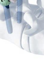
4 MATRIX Spine System Deformity A Solution for Simple and Complex Spine Pathology The Synthes MATRIX Spine System is a set of instruments and implants that cover degenerative, deformity, MIS and Trauma indications. Dual Core/Double Lead Screw Design Designed for fast and controlled insertion Designed to increase pull-out resistance due to enhanced bone purchase Designed for improved handling thanks to atraumatic tip and self tapping thread PrimeLock Screwdriver Screw Interlock Toggle free screw insertion Designed for precise and controlled screw placement Direction of screw insertion possible 2 DePuy Synthes MATRIX Spine System Deformity Surgical Technique


5 Modularity Click on and Preassembled Screws Customized inventory possible Designed for better visualization of the anatomical structure Multiple screw head removal and replacement without removing the bone screw from the pedicle Snap on Swiveling Transverse Connector Designed to provide fast in-situ placement Anatomical adjustment possible MATRIX Spine System Deformity Surgical Technique DePuy Synthes 1


6 MATRIX Spine System Deformity Implants Preassembled Polyaxial and Reduction Pedicle Screw Allows up to 50 of angulation to ease in situ connection to the longitudinal rod The rod reduction features are located at the top of the polyaxial head. Dual Core/Double Lead thread designed to securely anchor the screw in cortical and cancellous bone Threaded T25 Stardrive recess designed to deliver torque effectively Pedicle Screw Designed for increased visual access to the anatomical structures Designed to allow for improved access to the surgical field Dual Core/Double Lead thread designed to securely anchor the screw in cortical and cancellous bone Threaded T25 Stardrive recess designed to deliver torque effectively 4 DePuy Synthes MATRIX Spine System Deformity Surgical Technique


7 Click on Polyaxial and Reduction Screw Head The polyaxial head of the implant is designed for rod r e d u c t i o n To ease intraoperative planning, the polyaxial heads can be removed and replaced without removing the pedicle screw from the pedicle The reduction head allows for 15 mm rod reduction 15 mm Monoaxial Pedicle Screw The rod reduction features are raised to the top of the monoaxial head, allowing instruments to be attached and removed from the implant The low-profile head reduces the implant height above the bony anatomy Longitudinal grooves at the bottom of the screw head prevent the rod from derotating Hooks Wide array of hooks for various patient anatomy The low-profile head reduces the implant height above the bony anatomy The rod reduction features are raised to the top of the head, allowing instruments to be attached and removed from the implant Longitudinal grooves at the bottom of the screw head are designed to prevent the rod from derotating MATRIX Spine System Deformity Surgical Technique DePuy Synthes 1
8 MATRIX Spine System Deformity Implants Rods 5.5 mm diameter in pure titanium, titanium alloy and cobalt chrome A choice of straight, curved, and hex-end options to help ease intraoperative construct assembly and technique maneuvers Offered in a variety of lengths from 30 mm to 500 mm Connecting Rods 6.0 mm diameter tapered to 5.5 mm diameter 5.5 mm diameter tapered to 4.0 mm diameter (titanium alloy only) 5.5 mm diameter tapered to 3.5 mm diameter (titanium alloy only) Offered in titanium alloy (Ti-6AI-7Nb), titanium or cobalt-chrome alloy (CoCrMo) Available in 500 mm length Locking Caps Square thread design reduces cross threading under high reduction loads T25 Stardrive recess designed to reduce the risk of damage at high loads 1-step locking cap allows for complete fixation in one step (polyaxiality and run on rod) Available flat or with guidance 1 DePuy Synthes MATRIX Spine System Deformity Surgical Technique


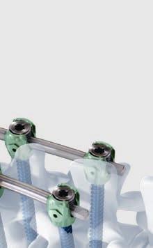
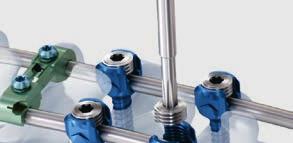
9 Transverse Connector The snap-on transverse connector is preassembled and requires only final positioning and tightening The jaws of the transverse connector swivel and are spring loaded Telescoping body is arched to accommodate grafts and anatomical structures and is available in a range of lengths The locking screws use a T15 Stardrive which reduces drive stripping while final tightening Open Titanium Transverse Bars Provide a lateral extension from the longitudinal rod to the monoaxial screw Available in lengths of 15 mm, 20 mm, 25 mm and 30 mm Reduces the need for severe rod contours which might otherwise be required for direct hook and screw-to-rod connection Instruments Ergonomically designed handles Intuitive, ease of use Convenient, interchangeable options MATRIX Spine System Deformity Surgical Technique DePuy Synthes 1
10 AO Spine Principles The four principles to be considered as the foundation for proper spine patient management underpin the design and delivery of the Curriculum: Stability Alignment Biology Function. 1,2 Stability Stabilization to achieve a specific therapeutic outcome axial sagittal coronal Alignment Balancing the spine in three dimensions Biology Etiology, pathogenesis, neural protection, and tissue healing Function Preservations and restoration of function to prevent disability Copyright 2012 by AOSpine 1 Aebi et al (1998) 2 Aebi et al (2007) 1 DePuy Synthes MATRIX Spine System Deformity Surgical Technique
11 Indications and Contraindications Intended use The MATRIX Spine System is a posterior pedicle screw and hook fixation system (T1 S2) intended to provide precise and segmental stabilization of the spine for use in skeletally mature patients. Indications Deformities (i.e. scoliosis, kyphosis and/or lordosis) Degenerative disc disease Spondylolisthesis Trauma (i.e. fracture or dislocation) Tumor Stenosis Pseudarthrosis Failed previous fusion Contraindications Osteoporosis In fractures and tumors with severe anterior vertebral body disruption, an additional anterior support or column reconstruction is required MATRIX Spine System Deformity Surgical Technique DePuy Synthes 9

12 Surgical Technique 1. Prepare pedicles and determine screw lengths Instruments Pedicle Probe B 3.7 mm with Silicone Handle, length 240 mm, for Pedicle Screws B 5.0 to 7.0 mm Pedicle Awl B 4.0 mm with Silicone Handle, length 255 mm, for Pedicle Screws B 5.0 to 7.0 mm Locate pedicles and use the awl to perforate the cortex. Use the probe to open the pedicle canal. Using radiographic imaging, confirm pedicle location, orientation and depth by inserting the probe. When selecting the appropriate length screw, use the markings on the probe to determine the pedicle depth. All MATRIX pedicle screws are self-tapping; however, if tapping is preferred, use the appropriate tap and tap handle. 11 DePuy Synthes MATRIX Spine System Deformity Surgical Technique
, length 180 mm 388.654 Ratchet with Handle, with Hexagonal Quick Coupling 6.0 mm 388.536 Pedicle Probe for Screws B 4.2 mm, length 240 mm 388.")

13 Optional instruments Pedicle Probe, thoracic Pedicle Probe, thoracic, small Pedicle Marker for Matrix Inserter for Pedicle Marker, for Matrix Taps, for Pedicle Screws, mm hex coupling (3.5 mm 9.0 mm), length 180 mm Ratchet with Handle, with Hexagonal Quick Coupling 6.0 mm Pedicle Probe for Screws B 4.2 mm, length 240 mm Feeler for Screw Channel, straight, B 2.3 mm, length 275 mm Feeler for Screw Channel, curved, B 2.3 mm, length 275 mm Feeler, straight, with rounded tip Pedicle Probe B 3.8 mm, curved, with Silicone Handle, length 290 mm, for Pedicle Screws B 5.0 to 7.0 mm Pedicle Awl B 3.0 mm, length 230 mm, for Screws B 4.0 and 4.2 mm MATRIX Spine System Deformity Surgical Technique DePuy Synthes 11
 onto the T25 Stardrive shaft. Next, slide the retaining sleeve onto the T25 Stardrive shaft.")

14 Surgical Technique 2. Assemble screwdriver for monoaxial screws Instruments Screwdriver Stardrive, with T-Handle, standard, for Matrix Retaining Sleeve, for Monoaxial Screws, standard, for Matrix 5.5 To assemble the monoaxial screwdriver, slide the finger spring (etched part C) onto the T25 Stardrive shaft. Next, slide the retaining sleeve onto the T25 Stardrive shaft. Turn the finger spring clockwise to engage the thread within the gray knob. Note: Remove the finger sleeve and retract the tube and tip for cleaning and sterilization. Optional instruments Screwdriver Shaft Stardrive, T25, standard, for Matrix Screwdriver Stardrive, T25, with straight handle, standard, for Matrix Retaining Sleeve for Monoaxial Screws, for Matrix Screwdriver Shaft Stardrive, T25, long, for Matrix Screwdriver Stardrive, T25, long, with T-Handle, for Matrix Screwdriver Stardrive, T25, long, with straight handle, for Matrix T-Handle with Ratchet Wrench, with Hexagonal Coupling 6.0 mm Handle with Ratchet Wrench, straight, with Hexagonal Coupling 6.0 mm 11 DePuy Synthes MATRIX Spine System Deformity Surgical Technique

15 3. Pick up screw Option A: Monoaxial pedicle screws Instruments Screwdriver Stardrive, with T-Handle, standard, for Matrix Retaining Sleeve, for Monoaxial Screws, standard, for Matrix 5.5 Choose the appropriate screw diameter and length based on pedicle probe feedback. Insert the screwdriver tip into the recess of the monoaxial pedicle screw and rotate the gray knob of the retaining sleeve clockwise until the tip of the sleeve is firmly attached to the pedicle screw. Verify the screw length with the template provided in the screw module. Optional instruments Screwdriver Shaft Stardrive, T25, standard, for Matrix Screwdriver Stardrive, T25, with straight handle, standard, for Matrix Retaining Sleeve for Monoaxial Screws, for Matrix Screwdriver Shaft Stardrive, T25, long, for Matrix Screwdriver Stardrive, T25, long, with T-Handle, for Matrix Screwdriver Stardrive, T25, long, with straight handle, for Matrix T-Handle with Ratchet Wrench, with Hexagonal Coupling 6.0 mm Handle with Ratchet Wrench, straight, with Hexagonal Coupling 6.0 mm MATRIX Spine System Deformity Surgical Technique DePuy Synthes 11


16 Surgical Technique Option B: Polyaxial pedicle screws Option B1: Polyaxial pedicle screws with retaining sleeve Instruments Screwdriver Stardrive, T25, long, with T-Handle, for Matrix Retaining Sleeve, long, for Matrix 5.5 To assemble the screwdriver and the retaining sleeve, hold the green knob only and slide the retaining sleeve over the screwdriver. To load a pedicle screw, retract the green knob distally, then slide the sleeve toward the handle of the screwdriver shaft until it stops. Insert the screwdriver tip into the recess of the polyaxial pedicle screw and rotate the green knob of the retaining sleeve clockwise until the tip of the sleeve is firmly attached to the polyaxial pedicle screw. Verify the screw length with the template provided in the screw module. Notes: Disassemble completely for cleaning and sterilization. Do not grasp the green knob during screw insertion as this will cause the retaining sleeve to disengage from the screw. Ensure that the polyaxial screw head remains free to adapt its position and is not restricted by, or does not rest on, bony structures. If necessary, adjust the screw height and/or ream space for the screw head. 11 DePuy Synthes MATRIX Spine System Deformity Surgical Technique
17 Optional instruments Screwdriver Shaft Stardrive, T25, standard, for Matrix Screwdriver Stardrive, with T-Handle, standard, for Matrix Screwdriver Stardrive, T25, with straight handle, standard, for Matrix Retaining Sleeve, standard, for Matrix Screwdriver Shaft Stardrive, T25, long, for Matrix Screwdriver Stardrive, T25, long, with straight handle, for Matrix T-Handle with Ratchet Wrench, with Hexagonal Coupling 6.0 mm Handle with Ratchet Wrench, straight, with Hexagonal Coupling 6.0 mm MATRIX Spine System Deformity Surgical Technique DePuy Synthes 11
.")
. Place the screwdriver tip securely into the T25 StarDrive recess of the polyaxial pedicle screw or bone screw (5).")
18 Surgical Technique Option B2: Polyaxial pedicle screws with retaining sleeve, locking 1 Instruments Screwdriver Stardrive, T25, long, with T-Handle, for Matrix Retaining Sleeve, locking, long 2 To assemble the screwdriver and the retaining sleeve, depress the loading collar on the proximal end of the holding sleeve (1). Then slide the sleeve toward the handle on the shaft until it stops (2). 3 Release the loading collar and verify that the holding sleeve is firmly attached to the screwdriver (3). Retract the green locking ring towards the handle (4). Place the screwdriver tip securely into the T25 StarDrive recess of the polyaxial pedicle screw or bone screw (5) DePuy Synthes MATRIX Spine System Deformity Surgical Technique


19 Rotate the grey knob of the holding sleeve clockwise, using the handle as countertorque. Firmly tighten to secure the implant (6). 6 Push the green locking ring toward the grey knob (7). If required, set the ratchet handle to the forward setting to insert the screw. To release the sleeve, retract the green locking ring towards the handle, rotate the silver knob counterclockwise and remove the screwdriver (8) 7 Precautions: Polyaxial screwheads need to remain free and mobile after insertion to allow accurate alignment to the rod during locking cap insertion and final tightening. The mobility of the screwhead cannot be assessed while the holding sleeve is attached. Disassemble completely for cleaning. 8 Optional instruments Screwdriver Shaft Stardrive, T25, standard, for Matrix Screwdriver Stardrive, with T-Handle, standard, for Matrix Screwdriver Stardrive, T25, with straight handle, standard, for Matrix Retaining Sleeve, locking Screwdriver Shaft Stardrive, T25, long, for Matrix Screwdriver Stardrive, T25, long, with straight handle, for Matrix T-Handle with Ratchet Wrench, with Hexagonal Coupling 6.0 mm Handle with Ratchet Wrench, straight, with Hexagonal Coupling 6.0 mm MATRIX Spine System Deformity Surgical Technique DePuy Synthes 11


20 Surgical Technique 4. Insert screw Option A: Monoaxial pedicle screws Instruments Screwdriver Stardrive, with T-Handle, standard, for Matrix Retaining Sleeve, for Monoaxial Screws, standard, for Matrix 5.5 Insert the screw. Hold the black part of the retaining sleeve during screw insertion. To disengage the retaining sleeve, turn the gray knob counterclockwise and remove the screwdriver. Note: Do not grasp the gray knob during screw insertion as this will cause the retaining sleeve to disengage from the screw. Optional instruments Screwdriver Shaft Stardrive, T25, standard, for Matrix Screwdriver Stardrive, T25, with straight handle, standard, for Matrix Retaining Sleeve for Monoaxial Screws, for Matrix Screwdriver Shaft Stardrive, T25, long, for Matrix Screwdriver Stardrive, T25, long, with T-Handle, for Matrix Screwdriver Stardrive, T25, long, with straight handle, for Matrix T-Handle with Ratchet Wrench, with Hexagonal Coupling 6.0 mm Handle with Ratchet Wrench, straight, with Hexagonal Coupling 6.0 mm 11 DePuy Synthes MATRIX Spine System Deformity Surgical Technique

21 Option B: Polyaxial pedicle screws Option B1: Polyaxial pedicle screws using Screwdriver with retaining sleeve Instruments Screwdriver Stardrive, T25, long, with T-Handle, for Matrix Retaining Sleeve, long, for Matrix 5.5 Insert the screw. Hold the black part of the retaining sleeve during screw insertion. To disengage the retaining sleeve, rotate the green knob counterclockwise and remove screwdriver Note: Do not grasp the green knob during screw insertion as this will cause the retaining sleeve to disengage from the screw. Optional instruments Screwdriver Shaft Stardrive, T25, standard, for Matrix Screwdriver Stardrive, with T-Handle, standard, for Matrix Screwdriver Stardrive, T25, with straight handle, standard, for Matrix Retaining Sleeve, standard, for Matrix Screwdriver Shaft Stardrive, T25, long, for Matrix Screwdriver Stardrive, T25, long, with straight handle, for Matrix T-Handle with Ratchet Wrench, with Hexagonal Coupling 6.0 mm Handle with Ratchet Wrench, straight, with Hexagonal Coupling 6.0 mm MATRIX Spine System Deformity Surgical Technique DePuy Synthes 11


22 Surgical Technique Option B2: Polyaxial pedicle screws with retaining sleeve, locking Instruments Screwdriver Stardrive, T25, long, with T-Handle, for Matrix Retaining Sleeve, locking, long Insert the screw. To release the sleeve, retract the green locking ring towards the handle, rotate the grey knob counterclockwise and remove the screwdriver. 22 DePuy Synthes MATRIX Spine System Deformity Surgical Technique
23 Optional instruments Screwdriver Shaft Stardrive, T25, standard, for Matrix Screwdriver Stardrive, with T-Handle, standard, for Matrix Screwdriver Stardrive, T25, with straight handle, standard, for Matrix Retaining Sleeve, locking Screwdriver Shaft Stardrive, T25, long, for Matrix Screwdriver Stardrive, T25, long, with straight handle, for Matrix T-Handle with Ratchet Wrench, with Hexagonal Coupling 6.0 mm Handle with Ratchet Wrench, straight, with Hexagonal Coupling 6.0 mm MATRIX Spine System Deformity Surgical Technique DePuy Synthes 22


24 Surgical Technique 5. Prepare for hook Option A: Prepare lamina for lamina hook Instruments Lamina Feeler, small, for Matrix Lamina Feeler, large, for Matrix Using the appropriate lamina feeler, separate the ligamentum flavum from the underside of the lamina to provide good bony contact with the lamina hook. 22 DePuy Synthes MATRIX Spine System Deformity Surgical Technique


25 Option B: Prepare pedicle for pedicle hook Instrument Pedicle Feeler, for Matrix Using the pedicle feeler, open the facet capsule and locate the pedicle. Remove a small piece of the inferior articular process to ensure proper seating of the pedicle hook. Pedicle hooks should be placed in an up-going direction only. MATRIX Spine System Deformity Surgical Technique DePuy Synthes 22


26 Surgical Technique Option C: Prepare transverse process for transverse process hook Instrument Transverse Process Finder for Matrix Use the transverse process finder to separate the ligamentum flavum from the underside of the transverse process. 22 DePuy Synthes MATRIX Spine System Deformity Surgical Technique


27 6. Insert hook Instruments Holding Forceps, lateral, for Hooks, for Matrix Holding Forceps, straight, for Hooks, for Matrix Holding Forceps, curved, for Hooks, for Matrix Hook Positioner, for Matrix Attach the desired hook to the appropriate MATRIX hook holding forceps. Place the hook in the desired location. The MATRIX hook positioner may also be used to facilitate placement of the hook. Place remaining hooks by repeating Steps 5 and 6 as determined in the preoperative plan. MATRIX Spine System Deformity Surgical Technique DePuy Synthes 22


28 Surgical Technique 7. Determine rod contour and length Instruments Trial Rod B 5.0 mm, length 150 mm Trial Rod B 5.0 mm, length 500 mm Alignment Tool for polyaxial Screw Head, for Matrix 5.5 Use the trial rod to determine contour and length of the rod. The rod template has graduations in 10 mm increments to determine the desired length. To adjust the alignment of the screw heads, use the polyaxial head alignment tool. Note: Ensure the polyaxial head alignment tool is seated into the head. Use tool to confirm that the head is still mobile and free from surrounding anatomy prior to inserting the rod. Select rod. Note on use of connecting rods: When connecting rods 3.5 mm/5.5 mm and 4.0 mm/5.5 mm are used, MATRIX can be linked to the Synapse, Axon and CerviFix 3.5 mm and 4.0 mm system, respectively. When 5.5 mm/6.0 mm connecting rods are used, the Synthes 6.0 mm rod systems can be linked to the MATRIX System. 22 DePuy Synthes MATRIX Spine System Deformity Surgical Technique


29 8. Contour and cut rod Instrument Rod Bender with Silicone Handle Optional instruments In-situ Bender for Rods B 5.5 mm, right In-situ Bender for Rods B 5.5 mm, left Bending Iron for Rods B 5.5 mm, left, for Coronal Plane Bending Iron for Rods B 5.5 mm, right, for Coronal Plane USS Rod Cutting and Bending Device Bolt Cutter Contour the rod to match the rod template, using the rod bender. Alternatively, in-situ benders or bending irons for the coronal plane may be used to contour the rod. Precautions: The USS rod cutting and bending device must be used to cut cobalt chromium rods. Do not reverse bend rods. Reverse bending may produce internal stresses which may become the focal point for eventual breakage of the implant. MATRIX Spine System Deformity Surgical Technique DePuy Synthes 22

30 Surgical Technique 9. Rod placement and reduction Instrument Holding Forceps for Rods B 5.5 and B 6.0 mm Use the rod holder to insert the rod into the openings of the top-loading screws or hooks. If necessary, the following instruments can aid with rod reduction. Optional instrument Rod Holding Forceps for Rods B 5.5 mm Note on use of connecting rods: When using a connecting rod, it is important not to position the transition taper within the head of a screw or hook. 22 DePuy Synthes MATRIX Spine System Deformity Surgical Technique

31 Option A: Rod reduction with a rod pusher Instruments Rod Pusher/Counter Torque, standard, for Matrix Handle, detachable, for Matrix Rod Pusher for Rods B 5.5/6.0 mm, for Matrix Place the rod into the screw or hook, using the rod pusher for 5.5 mm/6.0 mm rods or the standard rod pusher/ counter torque. The detachable handle connects with ease to the octagonal end of the rod pusher counter torque, providing an adjustable L-handle to apply downward force on the rod. Optional instrument Rod Pusher/Counter Torque, long, for Matrix 5.5 Precaution: If significant reduction forces are encountered, consider: screw height adjustments rod placement to reduce muscle entrapment. MATRIX Spine System Deformity Surgical Technique DePuy Synthes 22


32 Surgical Technique Option B: Rod reduction with a rocker fork Instruments Rocker Fork, small, for Matrix Rocker Fork, footed, for Matrix Rocker Fork, medium, for Matrix 5.5 Use a medium rocker fork to lever the rod into the head of the pedicle screw or hook. Technique tip: Use the footed MATRIX rocker fork to aid in reducing the rod into adjacent screw heads. Reduction travels: Small MATRIX Rocker Fork = 8.5 mm Footed MATRIX Rocker Fork = 7.5 mm Medium MATRIX Rocker Fork = 13 mm Precaution: If significant reduction forces are encountered, consider: screw height adjustments rod placement to reduce muscle entrapment. 33 DePuy Synthes MATRIX Spine System Deformity Surgical Technique


33 Option C: Rod reduction with a rod persuader Instrument Rod Persuader, standard, for Matrix 5.5 Ensure that the ratchet handle is fully open. Place the rod persuader over rod and onto the screw head. Press down firmly until the tips engage the head of the screw. Squeeze the handle to seat the rod into the head of the pedicle screw. Optional instrument Rod Introduction Pliers, long, for Matrix 5.5 Reduction travel: 15 mm Note: The rod persuader can be used as counter torque for final tightening of the locking cap. Precaution: If significant reduction forces are encountered, consider: screw height adjustments rod placement to reduce muscle entrapment. MATRIX Spine System Deformity Surgical Technique DePuy Synthes 33


34 Surgical Technique Option D: Rod reduction with a reduction instrument for Spondylolisthesis Instruments Socket, hexagonal 6.0 mm Reduction Instrument for Spondylolisthesis, standard, for Matrix Ratchet with Handle, with Hexagonal Quick Coupling 6.0 mm To assemble the instrument, slide the inner tube through the outer tube. Insert the cream nut and press down firmly until audible feedback. Push the inner tube up towards the cream nut and turn the cream nut clockwise until the black line is visible at the 30 line. Place the reduction instrument over the screw head. Press down firmly until the tips engage. Load the hexagonal socket into the ratchet handle and insert it into the top of the reduction instrument. Rotate the ratchet handle clockwise to reduce the rod into the screw head. Full reduction is achieved when the black line on the side of the instrument is visible at the 0 line. Remove the hexagonal socket to insert a locking cap through the instrument. To remove the instrument from the screw head, turn the palm handle counter-clockwise until the line on the side of the instrument is visible at the 30 line. Note: The reduction instrument for spondylolisthesis can be used as counter torque for final tightening of the locking cap. Reduction travel: 30 mm 33 DePuy Synthes MATRIX Spine System Deformity Surgical Technique
35 Optional instrument Reduction Instrument for Spondylolisthesis, long, for Matrix 5.5 Precaution: If significant reduction forces are encountered, consider: screw height adjustments rod placement to reduce muscle entrapment. MATRIX Spine System Deformity Surgical Technique DePuy Synthes 33


36 Surgical Technique 10. Insert 1-step locking cap Instruments Screwdriver Stardrive, with T-Handle, standard, for Matrix Rod Pusher/Counter Torque, standard, for Matrix Handle, detachable, for Matrix Insert the tip of the screwdriver shaft into the T25 recess of the locking cap. Press down firmly. The screwdriver shaft is self-retaining. To ensure desired cap alignment, insert the locking cap through the rod pusher/counter torque. Thread the locking cap clockwise into the implant head. 33 DePuy Synthes MATRIX Spine System Deformity Surgical Technique


 Examples of misalignment: The rod is")
 The rod is not perpendicular to the")
 A severe bend is positioned within the")
37 Precaution: Confirm that the rod is fully aligned to the polyaxial head. Improper alignment of the rod with respect to the MATRIX implant heads could lead to construct loosening. (1) Examples of misalignment: The rod is sitting high in the polyaxial head. (2) The rod is not perpendicular to the polyaxial head. (3) A severe bend is positioned within the polyaxial head. (4a, 4b) a 4b MATRIX Spine System Deformity Surgical Technique DePuy Synthes 33


38 Surgical Technique Optional instruments Screwdriver Shaft Stardrive, T25, standard, for Matrix Screwdriver Stardrive, T25, with straight handle, standard, for Matrix Screwdriver Shaft Stardrive, T25, long, for Matrix Screwdriver Stardrive, T25, long, with T-Handle, for Matrix Screwdriver Stardrive, T25, long, with straight handle, for Matrix Rod Pusher/Counter Torque, long, for Matrix T-Handle with Ratchet Wrench, with Hexagonal Coupling 6.0 mm Handle with Ratchet Wrench, straight, with Hexagonal Coupling 6.0 mm 33 DePuy Synthes MATRIX Spine System Deformity Surgical Technique

39 11. Correct deformity with in-situ bending (optional) Instruments In-situ Bender for Rods B 5.5 mm, right In-situ Bender for Rods B 5.5 mm, left Bending Iron for Rods B 5.5 mm, left, for Coronal Plane Bending Iron for Rods B 5.5 mm, right, for Coronal Plane Use the in-situ benders, right and left, to contour the rod in the sagittal plane. The bending irons, right and left, can also be used to contour the rod in the coronal plane. MATRIX Spine System Deformity Surgical Technique DePuy Synthes 33

40 Surgical Technique 12. Correct deformity with rod rotation (optional) If rod rotation is desired, the following options may be used. Ensure that the rod is captured with the locking cap, but is free to rotate within the head of the pedicle screw or hook. Option A: Rod holder for 5.5 mm/6.0 mm rods Instruments Screwdriver Stardrive, with T-Handle, standard, for Matrix Screwdriver Stardrive, T25, with straight handle, standard, for Matrix Holding Forceps for Rods B 5.5 and B 6.0 mm Use the holding forceps for 5.5 mm/6.0 mm rods to grasp the rod and slowly rotate it in the proper direction. Use either the T-handle or straight handle shaft to tighten the locking caps after achieving the desired rod rotation. 33 DePuy Synthes MATRIX Spine System Deformity Surgical Technique

41 Option B: Hex-end rods and rod rotation wrench Instruments Screwdriver Stardrive, with T-Handle, standard, for Matrix Screwdriver Stardrive, T25, with straight handle, standard, for Matrix Wrench, hexagonal for Rods B 5.5/6.0 mm, for Matrix If hex-end rods are used in the construct, the rod rotation wrench for 5.5 mm/6.0 mm hex-end rods can be applied to the hex end of the rod to rotate. Use either the T-handle straight handle shaft to tighten the locking caps after achieving the desired rod rotation. MATRIX Spine System Deformity Surgical Technique DePuy Synthes 33

42 Surgical Technique 13. Correct deformity with derotation instruments (optional) Instruments Screwdriver Stardrive, with T-Handle, standard, for Matrix Derotation Instrument for Matrix Screwdriver Stardrive, T25, long, with straight handle, for Matrix If a derotation maneuver is desired, ensure that the locking caps are not tightened. Place a derotation instrument over each selected screw. Use the instruments as leverage to maneuver the vertebral bodies. Insert either the T-handle or straight handle shaft through the derotation instruments to tighten the locking caps. 44 DePuy Synthes MATRIX Spine System Deformity Surgical Technique

43 14. Distract Instruments Distraction Fork Screwdriver Stardrive, with T-Handle, standard, for Matrix Screwdriver Stardrive, T25, with straight handle, standard, for Matrix Spreader Forceps, parallel, for Rods B 5.5 and B 6.0 mm Holding Forceps for Rods B 5.5 and B 6.0 mm When implants are too close together, the distraction fork can be used to open space between the screw heads to begin distraction. Use the holding forceps for 5.5 mm/6.0 mm rods as a point of fixation against which to distract. Use the parallel spreader forceps for 5.5 mm/6.0 mm rods to distract the construct. Once in the desired position, tighten the locking caps with either the T-handle or straight handle shaft. MATRIX Spine System Deformity Surgical Technique DePuy Synthes 44

44 Surgical Technique 15. Compress Instruments Screwdriver Stardrive, with T-Handle, standard, for Matrix Screwdriver Stardrive, T25, with straight handle, standard, for Matrix Compression Forceps, parallel, for Rods B 5.5 and B 6.0 mm Holding Forceps for Rods B 5.5 and B 6.0 mm Compression Forceps, parallel, for Rods B 5.5 and B 6.0 mm, for 2 Levels Use the holding forceps for 5.5 mm/6.0 mm rods as a fixed point on the rod to compress the construct. Once in the desired position, tighten the locking screws with either the T-handle or straight handle shaft. Use the two level parallel compression forceps if compression is required across multiple levels. 44 DePuy Synthes MATRIX Spine System Deformity Surgical Technique


45 16. Perform final tightening Instruments T-Handle with Ratchet Wrench and with Torque Limiter, 10 Nm Screwdriver Shaft Stardrive, T25, standard, straight tip, with Hexagonal Coupling, for Matrix Handle, detachable, for Matrix Counter Torque, standard, for Matrix 5.5 Place the counter torque over the head of the screw or hook. Attach the screwdriver shaft T-handle with ratchet wrench and with torque limiter. Insert the instrument through the counter torque cannula into the drive recess of the locking cap. Tighten until there is a tactile release. This indicates that the required 10 Nm of torque has been applied. Repeat for all locking caps. Warning: Final tightening of the locking caps should only be performed with a calibrated, Synthes 10 Nm torque handle. MATRIX screw implants achieve performance standard only when tightened to the required 10 Nm tightening torque. Notes: Always fully seat the rod pusher/counter torque on the rod. The instrument must be perpendicular to the rod during final tightening. The Straight Tip T25 Stardrive is intended for final tightening of locking caps only and not initial locking cap insertion. The Straight Tip T25 Stardrive will not retain locking caps. The handle of the counter torque must be oriented laterally or medially. Do not orient the handle of the countertorque in line with the rod. This action could cause misalignment of the rod with the implant. Correct Incorrect MATRIX Spine System Deformity Surgical Technique DePuy Synthes 44
46 Surgical Technique Optional instruments Screwdriver Shaft Stardrive, T25, standard for Matrix Rod Pusher/Counter Torque, standard, for Matrix Reduction Instrument for Spondylolisthesis, standard, for Matrix Rod Persuader, standard, for Matrix Screwdriver Shaft Stardrive, T25, long, straight tip, with Hexagonal Coupling, for Matrix Screwdriver Shaft Stardrive, T25, long, for Matrix Rod Pusher/Counter Torque, long, for Matrix Counter Torque, long, for Matrix Reduction Instrument for Spondylolisthesis, long, for Matrix Rod Introduction Pliers, long, for Matrix 5.5 Note: Alternatively, the reduction instrument for spondylolisthesis and the rod persuader can be used as counter torque for final tightening of the locking cap. 44 DePuy Synthes MATRIX Spine System Deformity Surgical Technique

 or unassembled pedicle screw (page 47) to insert screw.")

47 Optional Techniques Insert Reduction Screws Instruments Screwdriver Stardrive, with T-Handle, standard, for Matrix Rod Pusher/Counter Torque for Reduction Screw, for Matrix mm reduction T-Handle with Ratchet Wrench and with Torque Limiter, 10 Nm Retaining Sleeve, standard, for Matrix Tab Remover for Reduction Screws, for Matrix Rod Pusher/Counter Torque for Reduction Screws, for Matrix 5.5 Follow the technique for preassembled polyaxial screw (page 14) or unassembled pedicle screw (page 47) to insert screw. Place the counter torque over the screw head. Insert the locking cap through the counter torque. Turning the locking cap will reduce the rod into the screw head. MATRIX Spine System Deformity Surgical Technique DePuy Synthes 41


48 Optional Techniques Insert Reduction Screws To break off the reduction screw tabs, slide the tab removal tool over one side wall of the reduction head. Gently rock the tab removal tool medial then lateral to break the tab wall free from the polyaxial head. Alternative technique for locking cap insertion Instrument Holding Crown for Reduction Screws, for Matrix 5.5 The holding crown for reduction screws can be used instead of the counter torque to provide guidance for the locking cap insertion. 44 DePuy Synthes MATRIX Spine System Deformity Surgical Technique

49 Insert Unassembled Pedicle Screw 1. Unassembled pedicle screw insertion Instruments Screwdriver Stardrive, T25, long, with T-Handle, for Matrix Reamer for Pedicle Screws, for Matrix Prepare the pedicle and insert pedicle screws as recommended in Steps 1 to 2 of the surgical technique. Slide reamer over screwdriver shaft. Engage tip of screwdriver in unassembled pedicle screw. Ream until the black line is visible on the shaft. This indicates that there is enough room for the implant head. MATRIX Spine System Deformity Surgical Technique DePuy Synthes 44
50 Optional Techniques Insert Unassembled Pedicle Screw 2. Polyaxial head assembly Instrument Positioning Instrument for Polyaxial Screw Heads, for Matrix 5.5 To pick up a screw head, align the positioning instrument for polyaxial screw heads to the rod slot features on the poly axial head implant and press down. Position the placement tool with the polyaxial head over the unassembled pedicle screw and press down. To ensure the polyaxial head is securely attached to the unassembled pedicle screw, gently lift up on the placement tool and angulate the polyaxial head. To release the head placement tool, press the button located at the distal end of the instrument. Notes: If the polyaxial head does not successfully attach to the head of the bone screw, additional reaming or screw height adjustment may be required to ensure sufficient space exists to allow free mobility of the head. Polyaxial heads and screws can be assembled a maximum of three times. Care should be taken when reaming the most superior (and inferior) level to protect the facet joints. 44 DePuy Synthes MATRIX Spine System Deformity Surgical Technique


51 Polyaxial Head Removal Instruments Removal Instrument for Polyaxial Screw Heads, for Matrix Ratchet with Handle, with Hexagonal Quick Coupling 6.0 mm If required, the polyaxial head can be removed from the pedicle screw intraoperatively. Remove the locking cap and rod. Slide the inner shaft of the ratchet into the handle of the head removal tool and thread counter-clockwise until the black line is visible. Press the tip of the head removal tool into the polyaxial head. A tactile click may be felt. While holding the green silicone handle, thread the inner shaft clockwise until it stops. Lift to remove the head. To remove the implant head from the instrument, turn the ratchet counter-clockwise until the black line is visible. Pull the head off the instrument. Note: The removal instrument can be used to remove the polyaxial head of both unassembled as well as preassembled screws. To remove the polyaxial reduction head, the tabs must first be broken off. MATRIX Spine System Deformity Surgical Technique DePuy Synthes 44


52 Optional Techniques Add Transverse Connectors Instruments Retaining Sleeve for Transverse Connectors, Snap-on, for Matrix Screwdriver Stardrive, T15, short, for Matrix Length indicator for Transverse Connectors, Snap-on, for Matrix Torque-limiting Handle, 3 Nm Use the length indicator for transverse connector to indicate the distance between the two rods and note the reference number located on the back of the caliper scale (1 8). Select the appropriate transverse connector. Use the screwdriver and the torque limiting handle to secure the transverse connector to the rods. When tightening the setscrews a tactile release is felt. Note: Always use retaining sleeve when tightening the setscrew. Warning: The MATRIX transverse connector contains nitinol components. Implants that contain nitinol should not be used in patients with nickel sensitivities or allergies. 55 DePuy Synthes MATRIX Spine System Deformity Surgical Technique


53 Adding Rod-to-Rod Connectors Instruments Torque-limiting Handle, 3 Nm Screwdriver Shaft Stardrive, T15, standard Retaining Sleeve for Transverse Connectors, Snap-on, for Matrix Choose the snap-on open parallel connector according the rod diameters to be received. The diameters accepted are etched on both sides of the connector to ensure the correct rod size is attached to each opening. Precaution: Parallel connectors with one set screw should be used in pairs on each side of the construct. Connectors with two set screws can be used one per side of the construct. Attach the preferred connector to each rod. Mount the T15 screwdriver shaft to the 3 Nm torque-limiting handle and slide the retaining sleeve over the screwdriver shaft. To secure the connector to the rods, engage the T15 drive into each setscrew recess, slide the retractable retaining sleeve to the distal position. Tighten all the set screws until a tactile release is felt. MATRIX Spine System Deformity Surgical Technique DePuy Synthes 55
54 Optional Techniques Adding Rod-to-Rod Connectors Notes: If any part of the construct requires further adjustment, all set screws must be loosened to the point of resistance. Do not remove set screws from the assembly. After final adjustment, retighten the set screws. Parallel connectors contain Nitinol components. Implants that contain Nitinol should not be used in patients with nickel sensitivities or allergies. The retaining sleeve for transverse connectors cannot be used when tightening parallel with two set screws. Precautions: Care should be taken not to tighten the connector on a portion of the rod that has been contoured or deformed by a rod cutter. Synthes connectors are tested using Synthes 5.5 or 6.0 mm rods and not compatible with those rods of similar diameter from other manufacturers. Refer to the torque-limiting handle package and labeling for the recommended calibration maintenance. Optional Instrument Screwdriver Stardrive, T15, short, for Matrix 55 DePuy Synthes MATRIX Spine System Deformity Surgical Technique

55 Transverse Bar Attachment (for monoaxial screws only) The transverse bar provides an extension to the monoaxial screw in situations where the rod contour or patient anatomy prevents a direct screw-to-rod connection. Instruments Screwdriver Stardrive, T15, short, for Matrix Rod Pusher for Rods B 5.5/6.0 mm, for Matrix Torque-limiting Handle, 3 Nm Place the opening of the transverse bar over the 5.5 mm rod. Loosely attach the transverse bar to the rod by tightening the setcrew within the T15 stardrive screwdriver shaft and 3.0 Nm torque limiting handle. Introduce the transverse bar into the screw opening. Use the rod pusher for 5.5/6.0 mm rods. Secure the transverse bar to the screw by inserting the locking cap and tighten, following locking cap final tightening procedure (refer to step 8 of the surgical technique). Secure the transverse bar to the rod using the T15 stardrive screwdriver shaft and 3.0 Nm torque limiting handle. Tighten the setscrew firmly until a tactile release is felt. Warning: Final tightening of the setscrew should only be performed with a calibrated Synthes 3 Nm torque limiting handle. MATRIX Spine System Deformity Surgical Technique DePuy Synthes 55
56 Optional Techniques Locking Cap Removal Loosen locking cap Instruments T-Handle with Ratchet Wrench and with Torque Limiter, 10 Nm Screwdriver Shaft Stardrive, T25, standard, straight tip, with Hexagonal Coupling, for Matrix Handle, detachable, for Matrix Counter Torque, standard, for Matrix 5.5 To remove a locking cap, slide the counter torque with detachable handle over the screwhead. Place the ratchet of the torque limiting handle in the neutral position, engage a T25 screwdriver with the Stardrive recess of the locking cap and turn counter-clockwise. Note: Locking caps are designed to lock the construct safely and reduce the chance of postoperative loosening and rod-push-through. Therefore, in certain cases, the loosening torque may be higher than 10 Nm. In such cases, use the following techniques to remove a locking cap. Sequentially turn clockwise and then immediately counterclockwise. Turn until tactile or audible feedback from the implant is experienced. Repeat the steps until the locking cap is loose. Note: For this technique, always use the torque limiting handle ( ) to reduce risk of damage to the T25 screwdriver shaft. 55 DePuy Synthes MATRIX Spine System Deformity Surgical Technique
57 If after multiple attempts to loosen the locking cap the torque is still excessive, one of the following techniques should be used: Option A: Counter torque on a adjacent screw Instruments T-Handle with Ratchet Wrench and with Torque Limiter, 10 Nm Screwdriver Shaft Stardrive, T25, standard, straight tip, with Hexagonal Coupling, for Matrix Counter Torque, standard, for Matrix Handle, detachable, for Matrix Rod Pusher/Counter Torque, standard, for Matrix 5.5 Place the rod pusher/counter torque with detachable handle over an adjacent screw on the same rod (i.e. one level higher or lower). Simultaneously place the countertorque over the locking cap to be loosened and engage the screwdriver shaft and torque limiting handle with the stardrive recess of the locking cap. Place the ratchet of the torque limiting handle in the neutral position and begin to sequentially turn clockwise and then immediately counterclockwise. Turn until tactile or audible feedback from the implant is experienced. Repeat the steps until the locking cap is loose. Note: For this technique, always use the torque limiting handle ( ) to reduce risk of damage to the T25 screwdriver shaft. Retighten the locking cap on which the counter torque was applied to 10 Nm. MATRIX Spine System Deformity Surgical Technique DePuy Synthes 55

58 Optional Techniques Locking Cap Removal Option B: Apply a downward force to the rod Instruments T-Handle with Ratchet Wrench and with Torque Limiter, 10 Nm Screwdriver Shaft Stardrive, T25, long, straight tip, with Hexagonal Coupling, for Matrix Rod Introduction Pliers, long, for Matrix 5.5 Optional Instruments Screwdriver Shaft Stardrive, T25, standard, for Matrix Rod Persuader, standard, for Matrix 5.5 Apply a downward force to the rod. Place the Rod Persuader on the screw and firmly squeeze the handles. Place the ratchet of the torque limiting handle in the neutral position. With the reduction load applied begin to sequentially turn clockwise and then immediately counterclockwise. Turn until tactile or audible feedback from the implant is experienced. Repeat the steps until the locking cap is loose. Note: For this technique, always use the torque limiting handle ( ) to reduce risk of damage to the T25 screwdriver shaft. 55 DePuy Synthes MATRIX Spine System Deformity Surgical Technique
59 Implants* Monoaxial screws mm Titanium MATRIX Monoaxial Screws 20 mm 45 mm thread lengths mm Titanium MATRIX Monoaxial Screws 20 mm 55 mm thread lengths mm Titanium MATRIX Monoaxial Screws 20 mm 60 mm thread lengths mm Titanium MATRIX Monoaxial Screws 20 mm 65 mm thread lengths mm Titanium MATRIX Monoaxial Screws 25 mm 100 mm thread lengths mm Titanium MATRIX Monoaxial Screws 25 mm 100 mm thread lengths mm Titanium MATRIX Monoaxial Screws 30 mm 100 mm thread lengths * All implants are available sterile packed. Add suffix «S» to article number. MATRIX Spine System Deformity Surgical Technique DePuy Synthes 11
60 Implants Preassembled polyaxial screws Pedicle Screw Matrix 5.5 Polyaxial B 4.0 mm, preassembled, lengths mm, Titanium Alloy (TAN) Pedicle Screw Matrix 5.5 Polyaxial, B 5.0 mm, preassembled, length mm, Titanium Alloy (TAN) Pedicle Screw Matrix 5.5 Polyaxial B 5.5 mm, preassembled, length mm, Titanium Alloy (TAN) Pedicle Screw Matrix 5.5 Polyaxial B 6.0 mm, preassembled, lengths mm, Titanium Alloy (TAN) Pedicle Screw Matrix 5.5 Polyaxial B 7.0 mm, preassembled, lengths mm, Titanium Alloy (TAN) Pedicle Screw Matrix 5.5 Polyaxial B 8.0 mm, preassembled, lengths mm, Titanium Alloy (TAN) Pedicle Screw Matrix 5.5 Polyaxial B 9.0 mm, preassembled, lengths mm, Titanium Alloy (TAN) 55 DePuy Synthes MATRIX Spine System Deformity Surgical Technique
 04.639.620 Pedicle Screw Matrix 5.5 B 6.0 mm, 04.639.665 lengths 20 65 mm, Titanium Alloy (TAN) 04.639.725 Pedicle Screw Matrix 5.")
61 Bone screws Pedicle Screw Matrix 5.5 B 4.0 mm, lengths mm, Titanium Alloy (TAN) Pedicle Screw Matrix 5.5 B 5.0 mm, lengths mm, Titanium Alloy (TAN) Pedicle Screw Matrix 5.5 B 5.5 mm, length mm, Titanium Alloy (TAN) Pedicle Screw Matrix 5.5 B 6.0 mm, lengths mm, Titanium Alloy (TAN) Pedicle Screw Matrix 5.5 B 7.0 mm, lengths mm, Titanium Alloy (TAN) Pedicle Screw Matrix 5.5 B 8.0 mm, lengths mm, Titanium Alloy (TAN) Pedicle Screw Matrix 5.5 B 9.0 mm, lengths mm, Titanium Alloy (TAN) Screw heads Screw Head, polyaxial, for Matrix 5.5, Titanium Alloy (TAN) Reduction Head, polyaxial, for Matrix 5.5, Titanium Alloy (TAN) MATRIX Spine System Deformity Surgical Technique DePuy Synthes 55
 04.634.620 Reduction Screw Matrix 5.5 B 6.0 mm, 04.634.665 lengths 20 65 mm, Titanium Alloy (TAN) 04.634.725 Reduction Screw Matrix 5.")
 04.632.000 Locking Cap, one-step, for Matrix 5.")
62 Implants Preassembled reduction screws Reduction Screw Matrix 5.5 B 4.0 mm, lengths mm, Titanium Alloy (TAN) Reduction Screw Matrix 5.5 B 5.0 mm, lengths mm, Titanium Alloy (TAN) Reduction Screw Matrix 5.5 B 5.5 mm, length mm, Titanium Alloy (TAN) Reduction Screw Matrix 5.5 B 6.0 mm, lengths mm, Titanium Alloy (TAN) Reduction Screw Matrix 5.5 B 7.0 mm, lengths mm, Titanium Alloy (TAN) Reduction Screw Matrix 5.5 B 8.0 mm, lengths mm, Titanium Alloy (TAN) Locking cap Locking Cap, flat, one-step, for Matrix 5.5, Cobalt-chrome alloy (CoCrMo) Locking Cap, one-step, for Matrix 5.5 Titanium Alloy (TAN) 11 DePuy Synthes MATRIX Spine System Deformity Surgical Technique
63 Rods Scoliosis Rod B 5.5 mm, prebent, length 400/80 mm, Pure Titanium Scoliosis Rod B 5.5 mm, prebent, length 400/80 mm, Titanium Alloy (TAN) Scoliosis Rod B 5.5 mm, prebent, length 400/80 mm, Cobalt-Chrome Alloy (CoCrMo) Rod B 5.5 mm, hard, length 200 mm, Pure Titanium Rod B 5.5 mm, hard, length 300 mm, Pure Titanium Rod B 5.5 mm, hard, length 400 mm, Pure Titanium Rod B 5.5 mm, hard, length 500 mm, Pure Titanium Rod B 5.5 mm, hard, length 200 mm, Titanium Alloy (TAN) Rod B 5.5 mm, hard, length 300 mm, Titanium Alloy (TAN) Rod B 5.5 mm, hard, length 400 mm, Titanium Alloy (TAN) Rod B 5.5 mm, hard, length 500 mm, Titanium Alloy (TAN) Rod B 5.5 mm, length 200 mm, Cobalt-Chrome Alloy (CoCrMo) Rod B 5.5 mm, length 300 mm, Cobalt-Chrome Alloy (CoCrMo) Rod B 5.5 mm, length 400 mm, Cobalt-Chrome Alloy (CoCrMo) Rod B 5.5 mm, length 500 mm, Cobalt-Chrome Alloy (CoCrMo) MATRIX Spine System Deformity Surgical Technique DePuy Synthes 11
64 Implants Rod B 5.5 mm, hard, length 500 mm, with Hexagonal End, Pure Titanium Rod B 5.5 mm, length 500 mm, with Hexagonal End, Cobalt-chrome alloy (CoCrMo) Rod B 5.5 mm, hard, length 500 mm, with Hexagonal End, Titanium Alloy (TAN) Connecting Rod B 5.5/6.0 mm, length 500 mm, Pure Titanium Connecting Rod B 5.5/6.0 mm, length 500 mm, Titanium Alloy (TAN) Connecting Rod B 3.5/5.5 mm, length 500 mm, Titanium Alloy (TAN) Connecting Rod B 4.0/5.5 mm, length 500 mm, Titanium Alloy (TAN) Connecting Rod B 5.5/6.0 mm, length 500 mm, Cobalt-chrome alloy (CoCrMo) 12 DePuy Synthes MATRIX Spine System Deformity Surgical Technique


65 Snap On Transverse Connector length size mm mm mm mm mm mm mm mm 8 Snap On Open Parallel Connectors diameters set screws to 5.5 mm to 6.0 mm to 6.0 mm to 5.5 mm to 6.0 mm to 6.0 mm 2 MATRIX Spine System Deformity Surgical Technique DePuy Synthes 11
66 Implants Hooks Titanium MATRIX Lamina Hooks Extra Small Small Medium Large Small, Straight Large, Straight Thoracic Medium, Tall Body Large, Tall Body Offset right Offset left Angled upwards Angled downwards Titanium MATRIX Pedicle Hooks Small Medium Titanium MATRIX Transverse Process Hooks Right Left 14 DePuy Synthes MATRIX Spine System Deformity Surgical Technique

67 Instruments For pedicle preparation Tap for Pedicle Screws, length 180 mm mm mm mm mm mm mm mm mm Ball Tip Probes Feeler for Screw Channel, straight, B 2.3 mm, length 275 mm Feeler for Screw Channel, curved, B 2.3 mm, length 275 mm Feeler, straight, with rounded tip Pedicle Marker for Matrix Inserter for Pedicle Marker, for Matrix MATRIX Spine System Deformity Surgical Technique DePuy Synthes 11

68 Instruments Awls and Probes Pedicle Awl B 3.0 mm, length 230 mm, for Screws B 4.0 and 4.2 mm Pedicle Awl B 4.0 mm with Silicone Handle, length 255 mm, for Pedicle Screws B 5.0 to 7.0 mm Pedicle Probe, thoracic Pedicle Probe, thoracic, small Pedicle Probe for Screws B 4.2 mm, length 240 mm Pedicle Probe B 3.7 mm with Silicone Handle, length 240 mm, for Pedicle Screws B 5.0 to 7.0 mm Pedicle Probe B 3.8 mm, curved, with Silicone Handle, length 290 mm, for Pedicle Screws B 5.0 to 7.0 mm 11 DePuy Synthes MATRIX Spine System Deformity Surgical Technique

69 For screw insertion Retaining Sleeves Retaining Sleeve, for Monoaxial Screws, standard, for Matrix Retaining Sleeve for Monoaxial Screws, for Matrix Retaining Sleeve, standard, for Matrix Retaining Sleeve, long, for Matrix Retaining Sleeve, locking Retaining Sleeve, locking, long T25 Stardrive Shafts Screwdriver Shaft Stardrive, T25, standard, for Matrix Screwdriver Shaft Stardrive, T25, long, for Matrix Screwdriver Shaft Stardrive, T25, standard, straight tip, with Hexagonal Coupling, for Matrix Screwdriver Shaft Stardrive, T25, long, straight tip, with Hexagonal Coupling, for Matrix Screwdrivers Stardrive T25 with T Handle Screwdriver Stardrive, with T-Handle, standard, for Matrix Screwdriver Stardrive, T25, long, with T-Handle, for Matrix MATRIX Spine System Deformity Surgical Technique DePuy Synthes 11
70 Instruments Straight Handle T25 Stardrive Screwdriver Stardrive, T25, with straight handle, standard, for Matrix Screwdriver Stardrive, T25, long, with straight handle, for Matrix Ratchet Wrench T-Handle with Ratchet Wrench, with Hexagonal Coupling 6.0 mm Handle with Ratchet Wrench, straight, with Hexagonal Coupling 6.0 mm 11 DePuy Synthes MATRIX Spine System Deformity Surgical Technique

71 For assembly and removal of polyaxial screw heads Alignment Tool for polyaxial Screw Head, for Matrix Positioning Instrument for Polyaxial Screw Heads, for Matrix Removal Instrument for Polyaxial Screw Heads, for Matrix Reamer for Pedicle Screws, for Matrix Loading Station for Matrix 5.5 MATRIX Spine System Deformity Surgical Technique DePuy Synthes 19


72 Instruments For hook placement Lamina Feeler, small, for Matrix Lamina Feeler, large, for Matrix Holding Forceps, lateral, for Hooks, for Matrix Holding Forceps, straight, for Hooks, for Matrix Holding Forceps, curved, for Hooks, for Matrix Hook Positioner, for Matrix Pedicle Feeler, for Matrix Transverse Process Finder for Matrix 11 DePuy Synthes MATRIX Spine System Deformity Surgical Technique


73 For rod cutting and bending Trial Rod B 5.0 mm, length 150 mm Trial Rod B 5.0 mm, length 500 mm USS Rod Cutting and Bending Device Bolt Cutter Rod Bender with Silicone Handle In Situ Benders, for 5.5 mm rods In-situ Bender for Rods B 5.5 mm, right In-situ Bender for Rods B 5.5 mm, left Bending Irons for Coronal Plane, for 5.5 mm rods Bending Iron for Rods B 5.5 mm, left, for Coronal Plane Bending Iron for Rods B 5.5 mm, right, for Coronal Plane MATRIX Spine System Deformity Surgical Technique DePuy Synthes 11


74 Instruments For rod insertion Wrench, hexagonal for Rods B 5.5/6.0 mm, for Matrix Rod Holding Forceps for Rods B 5.5 mm Rod Pusher for Rods B 5.5/6.0 mm, for Matrix Holding Forceps for Rods B 5.5 and B 6.0 mm 12 DePuy Synthes MATRIX Spine System Deformity Surgical Technique


75 For rod reduction Reduction Instruments Reduction Instrument for Spondylolisthesis, standard, for Matrix Reduction Instrument for Spondylolisthesis, long, for Matrix Socket, hexagonal 6.0 mm Ratchet with Handle, with Hexagonal Quick Coupling 6.0 mm Rod Persuaders Rod Persuader, standard, for Matrix Rod Introduction Pliers, long, for Matrix 5.5 MATRIX Spine System Deformity Surgical Technique DePuy Synthes 11

76 Instruments Rocker Forks Rocker Fork, small, for Matrix Rocker Fork, footed, for Matrix Rocker Fork, medium, for Matrix 5.5 Instruments for reduction screws Counter Torque for Reduction Screws, for Matrix Rod Pusher/Counter Torque for Reduction Screw, for Matrix Rod Pusher/Counter Torque for Reduction Screws, for Matrix Holding Crown for Reduction Screws, for Matrix Tab Remover for Reduction Screws, for Matrix 14 DePuy Synthes MATRIX Spine System Deformity Surgical Technique


77 For cap introduction and tightening T-Handle with Ratchet Wrench and with Torque Limiter, 10 Nm Rod Pusher / Counter Torques Rod Pusher/Counter Torque, standard, for Matrix Rod Pusher/Counter Torque, long, for Matrix Counter Torque, standard, for Matrix Counter Torque, long, for Matrix Handle, detachable, for Matrix MATRIX Spine System Deformity Surgical Technique DePuy Synthes 11


78 Instruments For rotation correction Derotation Instrument for Matrix 5.5 For distraction and compression Distraction Fork Compression Forceps, parallel, for Rods B 5.5 and B 6.0 mm Spreader Forceps, parallel, for Rods B 5.5 and B 6.0 mm Compression Forceps, parallel, for Rods B 5.5 and B 6.0 mm, for 2 Levels 11 DePuy Synthes MATRIX Spine System Deformity Surgical Technique


79 For transverse and parallel connectors Retaining Sleeve for Transverse Connectors, Snap-on, for Matrix Screwdriver Stardrive, T15, short, for Matrix Screwdriver Shaft Stardrive, T15, standard (straight tip) Length indicator for Transverse Connectors, Snap-on, for Matrix Torque-limiting Handle, 3 Nm MATRIX Spine System Deformity Surgical Technique DePuy Synthes 11
MATRIX Spine System Deformity. A posterior pedicle screw, hook, and rod fixation system.
 MATRIX Spine System Deformity. A posterior pedicle screw, hook, and rod fixation system. Technique Guide Instruments and implants approved by the AO Foundation Table of Contents Introduction MATRIX Spine
MATRIX Spine System Degenerative. A posterior pedicle screw and rod fixation system.
 MATRIX Spine System Degenerative. A posterior pedicle screw and rod fixation system. Technique Guide Instruments and implants approved by the AO Foundation Table of Contents Introduction MATRIX Spine
USS Variable Axis Screw (VAS) System. For posterior fixation of the lumbar spine.
 System. For posterior fixation of the lumbar spine.") USS Variable Axis Screw (VAS) System. For posterior fixation of the lumbar spine. Technique Guide Instruments and implants approved by the AO Foundation Table of Contents Introduction USS Variable Axis
USS Variable Axis Screw (VAS) System. For posterior fixation of the lumbar spine. Technique Guide Instruments and implants approved by the AO Foundation Table of Contents Introduction USS Variable Axis
The Versatile Polyaxial Solution for the Universal Spine Systems. USS II Polyaxial. Surgical Technique
 The Versatile Polyaxial Solution for the Universal Spine Systems USS II Polyaxial Surgical Technique Image intensifier control This description alone does not provide sufficient background for direct use
A Fusion of Versatility, Performance and Ease.
 MATRIX Spine System. Degenerative and Deformity. System Guide A Fusion of Versatility, Performance and Ease. Instruments and implants approved by the AO Foundation The MATRIX Spine System is a universal
Technique Guide. Universal Spinal System (USS). Designed to achieve the goals of scoliosis surgery.
. Designed to achieve the goals of scoliosis surgery.") Technique Guide Universal Spinal System (USS). Designed to achieve the goals of scoliosis surgery. Table of Contents Introduction Universal Spinal System 2 AO ASIF Principles of Internal Fixation 3 Indications
Technique Guide Universal Spinal System (USS). Designed to achieve the goals of scoliosis surgery. Table of Contents Introduction Universal Spinal System 2 AO ASIF Principles of Internal Fixation 3 Indications
Technique Guide. Pangea Spine System. Top loading pedicle screw and hook system for posterior stabilization and correction of spinal deformities.
 Technique Guide Pangea Spine System. Top loading pedicle screw and hook system for posterior stabilization and correction of spinal deformities. Table of Contents Introduction Pangea Spine System 4 Dual
Dual-Opening USS. For deformity correction.
 Dual-Opening USS. For deformity correction. Technique Guide Instruments and implants approved by the AO Foundation Table of Contents Introduction Dual-Opening USS 2 AO Principles 4 Indications 5 Preoperative
Handling instructions. USS Low Profile. Thoracolumbar posterior fixation system.
 Handling instructions USS Low Profile. Thoracolumbar posterior fixation system. U Table of contents Introduction Indications and contraindications 3 USS Low Profile implants 4 Handling implants with stick
Valencia Pedicle Screw Surgical Technique
 Valencia Pedicle Screw Surgical Technique VALENCIA CIRCUIT TABLE OF CONTENTS Design Rationale Indications for Use Surgical Technique 1. Pedicle Preparation 2. Screw Insertion 3. Rod Placement 4. Locking
USS Variable Axis Screw
 USS Variable Axis Screw Polyaxial side-opening pedicle screw Surgical technique Original Instruments and Implants of the Association for the Study of Internal Fixation AO/ASIF USS Variable Axis Screw
TSLP Thoracolumbar Spine Locking Plate
 Anterior thoracolumbar spine locking plate TSLP Thoracolumbar Spine Locking Plate Surgical Technique Image intensifier control This description alone does not provide sufficient background for direct use
VECTRA-T SURGICAL TECHNIQUE. The Translational Anterior Cervical Palate System. This publication is not intended for distribution in the USA.
 VECTRA-T The Translational Anterior Cervical Palate System This publication is not intended for distribution in the USA. SURGICAL TECHNIQUE Image intensifier control This description alone does not provide
The CerviFix System. Including the StarLock Components. CerviFix Clamp and Screw. StarLock Clamp and Screw
 The CerviFix System Including the StarLock Components CerviFix Clamp and Screw StarLock Clamp and Screw The CerviFix System The CerviFix System is a comprehensive set of implants, including clamps, screws,
Technique Guide. MATRIX Spine System MIS Instrumentation. The total solution for simple and complex spine pathology.
 Technique Guide MATRIX Spine System MIS Instrumentation. The total solution for simple and complex spine pathology. Table of Contents Introduction MATRIX Spine System MIS Instrumentation 2 AO Principles
TELEFIX SURGICAL TECHNIQUE. Implant system for the anterior stabilization of the thoracolumbar spine
 TELEFIX Implant system for the anterior stabilization of the thoracolumbar spine Instruments and implants approved by the AO Foundation. This publication is not intended for distribution in the USA. SURGICAL
USS II ILIO-SACRAL Modular System for Stable Fixation in the Sacrum and Illium
 USS II ILIO-SACRAL Modular System for Stable Fixation in the Sacrum and Illium Instruments and implants approved by the AO Foundation. This publication is not intended for distribution in the USA. TECHNIQUE
X-spine Surgical Technique
 X-spine Surgical Technique The X90 Pedicle Screw System Revolutionary Design and Function This document is intended exclusively for experts in the field, particularly physicians, and is not intended for
Y o u r Id e a s En g i n e e r e d t o Li f e
 ISSYS LP Spinal Fixation System Surgical Guide Y o u r Id e a s En g i n e e r e d t o Li f e In t r o d u c t i o n ISSYS LP Sp i n a l Fixation System The foundation of the ISSYS LP Spinal Fixation System
operative technique Universal Application
 operative technique Universal Application Introduction Introduction Building upon the design rationale of the Xia Spinal System, the new Xia Spinal System represents the latest advancement in spinal implant
Technique Guide. USS Small Stature/Pediatric. A multifaceted deformity system for use in patients of small stature.
 Technique Guide USS Small Stature/Pediatric. A multifaceted deformity system for use in patients of small stature. Image intensifier control Warning This description alone does not provide sufficient background
EXCELLA ll. Spinal System
 EXCELLA ll Spinal System Excella II Spinal System INDICATIONS FOR USE The Innovasis Excella II Spinal System is intended for use in the non-cervical area of the spine. WARNING: The safety and effectiveness
Technique Guide. NFlex. Semi-rigid rods for posterior lumbar stabilization.
 Technique Guide NFlex. Semi-rigid rods for posterior lumbar stabilization. Table of Contents Introduction NFlex 2 Indications and Contraindications 4 NFlex Principles 6 Surgical Technique Preoperative
Thoracolumbar Spine Locking Plate (TSLP) System. A low-profile plating system for anterior stabilization of the thoracic and lumbar spine.
 System. A low-profile plating system for anterior stabilization of the thoracic and lumbar spine.") Thoracolumbar Spine Locking Plate (TSLP) System. A low-profile plating system for anterior stabilization of the thoracic and lumbar spine. Technique Guide Instruments and implants approved by the AO Foundation
Thoracolumbar Spine Locking Plate (TSLP) System. A low-profile plating system for anterior stabilization of the thoracic and lumbar spine. Technique Guide Instruments and implants approved by the AO Foundation
L8 Spine System SURGICAL TECHNIQUE. Add: No.1-8, Tianshan Road, Xinbei District, Changzhou, Jiangsu, China
 Add: No.-8, Tianshan Road, Xinbei District, Changzhou, Jiangsu, China 23022 Tel: 0086 59 8595556 Fax: 0086 59 859555 Http://www.kanghui.com Add: F25, Shanghai International Pharmaceutical Trad & Exhibition
Occipital Cervical Fusion System. Implants and instruments designed to optimize fixation to the occiput.
 Occipital Cervical Fusion System. Implants and instruments designed to optimize fixation to the occiput. Technique Guide and implants approved by the AO Foundation Table of Contents Introduction Occipital
XRL A modular expandable radiolucent vertebral body replacement system
 XRL A modular expandable radiolucent vertebral body replacement system This publication is not intended for distribution in the USA. SURGICAL TECHNIQUE Table of Contents Introduction XRL 2 AO Spine Principles
Comprehensive posterior and anterior deformity system with screws and hooks with dual opening USS II. Surgical Technique
 Comprehensive posterior and anterior deformity system with screws and hooks with dual opening USS II Surgical Technique Image intensifier control This description alone does not provide sufficient background
PRODUCT SUMMARY Cobalt Chrome Tulip Multiple Options Triple Lead Thread
 PRODUCT SUMMARY Cobalt Chrome Tulip Multiple Options Triple Lead Thread Screws Low Profile 2.72 Footprint x 2.5 Height Square Threaded Locking Cap Geometry reduces risk of cross threading Hexalobular Drive
The Top-loading Pedicle Screw and Rod System Designed for the Posterior Stabilization of the Lower Back. Click X System. Surgical Technique
 The Top-loading Pedicle Screw and Rod System Designed for the Posterior Stabilization of the Lower Back Click X System Surgical Technique Image intensifier control This description alone does not provide
MATRIX Spine System Perforated
 The total solution for simple and complex spine pathology MATRIX Spine System Perforated Surgical Technique Image intensifier control Warning This description alone does not provide sufficient background
Thoracolumbar Anterior Compression (TAC) System. Allows distraction, compression, and lateral fixation of the lower thoracic and lumbar spine.
 System. Allows distraction, compression, and lateral fixation of the lower thoracic and lumbar spine.") Thoracolumbar Anterior Compression (TAC) System. Allows distraction, compression, and lateral fixation of the lower thoracic and lumbar spine. Technique Guide Instruments and implants approved by the AO
Thoracolumbar Anterior Compression (TAC) System. Allows distraction, compression, and lateral fixation of the lower thoracic and lumbar spine. Technique Guide Instruments and implants approved by the AO
BAK/C Cervical Anterior Interbody Fusion System
 Surgical Technique BAK/C Cervical Anterior Interbody Fusion System The Comfortable Choice for Cervical Fusion BAK/C Cervical Surgical Technique 1 The BAK/C Cervical Fusion System is an alternative to conventional
ARCH Laminoplasty System
 Dedicated System for Open-door Laminoplasty ARCH Laminoplasty System Surgical Technique Image intensifier control This description alone does not provide sufficient background for direct use of DePuy Synthes
SURGICAL TECHNIQUE GUIDE SOLANAS. Posterior Cervico-Thoracic Fixation System Adjustable Bridge System
 SURGICAL TECHNIQUE GUIDE SOLANAS Posterior Cervico-Thoracic Fixation System Adjustable Bridge System 2 SURGICAL TECHNIQUE GUIDE Preface SOLANAS Posterior Cervico-Thoracic Fixation System is designed to
VERTEX SELECT. surgical technique. adjustability. Flexibility. adaptability. Reconstruction System
 VERTEX SELECT Reconstruction System surgical technique adjustability. Flexibility. adaptability. adjustability. Flexibility. adaptability. The VERTEX SELECT Reconstruction System is a comprehensive set
HydraLok. Operative Technique. Polyaxial Pedicle Screw System
 HydraLok Operative Technique Polyaxial Pedicle Screw System Table of Contents Introduction...1 OPERATIVE TECHNIQUE OVERVIEW...2 DETAILED OPERATIVE TECHNIQUE...4 LOCATE AND PREPARE THE PEDICLE...4 PROBE
Technique Guide. 3.5 mm LCP Low Bend Medial Distal Tibia Plates. Part of the Synthes locking compression plate (LCP) system.
 system.") Technique Guide 3.5 mm LCP Low Bend Medial Distal Tibia Plates. Part of the Synthes locking compression plate (LCP) system. Table of Contents Introduction 3.5 mm LCP Low Bend Medial Distal Tibia Plates
Technique Guide 3.5 mm LCP Low Bend Medial Distal Tibia Plates. Part of the Synthes locking compression plate (LCP) system. Table of Contents Introduction 3.5 mm LCP Low Bend Medial Distal Tibia Plates
A U X I L I A R Y C O N N E C T O R S Surgical Technique
 A U X I L I A R Y C O N N E C T O R S Surgical Technique AUXILIARY CONNECTORS ISSYS LP Auxiliary Connectors The ISSYS LP auxiliary connectors were designed to provide medial-lateral variability for the
Surgical Technique. Occipito-Cervico-Thoracic System
 OASYS Surgical Technique Occipito-Cervico-Thoracic System System Overview The OASYS Occipito-Cervico-Thoracic System was developed to provide the surgeon with versatility for the treatment of pathologies
Dymaxeon Spine System. Simple, Streamlined, Smart. Surgical Procedure
 Simple, Streamlined, Smart Surgical Procedure Introduction The Dymaxeon pedicle screw system offers the spinal surgeon an outstanding system for stabilization of spinal deformity, reduction of spondylolisthesis,
Surgical Technique FOR U.S. DOMESTIC USE ONLY
 Surgical Technique FOR U.S. DOMESTIC USE ONLY Polyaxial Screws HA Coated Polyaxial Screws Uniplanar Screws Reduction Screws Reduction Uniplanar Screws Modular Screws TABLE OF CONTENTS Reform Pedicle Screw
Interbody fusion cage for the transforaminal approach. Travios. Surgical Technique
 Interbody fusion cage for the transforaminal approach Travios Surgical Technique Image intensifier control This description alone does not provide sufficient background for direct use of DePuy Synthes
The vertebral body replacement with ratchet mechanism. Synex. Surgical Technique
 The vertebral body replacement with ratchet mechanism Synex Surgical Technique Image intensifier control This description alone does not provide sufficient background for direct use of DePuy Synthes products.
EXPEDIUM VERSE Spinal System
 EXPEDIUM VERSE Spinal System SYSTEM GUIDE CONTENTS 1. PRODUCT OVERVIEW 1 FEATURES AND BENEFITS 1 IMPLANT DESIGN 5 INSTRUMENT DESIGN AND SET CONFIGURATION 6 SET CONTENTS 7 2. SURGICAL TECHNIQUE 9 SCREW
Technique Guide. 3.5 mm LCP Olecranon Plates. Part of the Synthes locking compression plate (LCP) system.
 system.") Technique Guide 3.5 mm LCP Olecranon Plates. Part of the Synthes locking compression plate (LCP) system. Table of Contents Introduction 3.5 mm LCP Olecranon Plates 2 AO Principles 3 Indications 3 Clinical
Technique Guide 3.5 mm LCP Olecranon Plates. Part of the Synthes locking compression plate (LCP) system. Table of Contents Introduction 3.5 mm LCP Olecranon Plates 2 AO Principles 3 Indications 3 Clinical
ONE SYSTEM, MULTIPLE OPTIONS. Surgical Technique. Hip Knee Spine Navigation
 ONE SYSTEM, MULTIPLE OPTIONS Surgical Technique Hip Knee Spine Navigation MUST MINI Surgical Technique Hip Knee Spine Navigation INTRODUCTION The M.U.S.T. Mini posterior cervical screw system is a modular
Augmentable Pedicle Screws for Osteoporotic Bone. Perforated Click X. Surgical Technique
 Augmentable Pedicle Screws for Osteoporotic Bone Perforated Click X Surgical Technique Image intensifier control This description alone does not provide sufficient background for direct use of DePuy Synthes
LCP Medial Distal Tibia Plate, without Tab. The Low Profile Anatomic Fixation System with Angular Stability and Optimal Screw Orientation.
 LCP Medial Distal Tibia Plate, without Tab. The Low Profile Anatomic Fixation System with Angular Stability and Optimal Screw Orientation. Technique Guide LCP Small Fragment System Table of Contents Introduction
SURGICAL TECHNIQUE. Standard Reduction HA Coated Modular. Discover the Difference
 SURGICAL TECHNIQUE Standard Reduction HA Coated Modular Discover the Difference TABLE OF CONTENTS REFORM PEDICLE SCREW SYSTEM OVERVIEW 3 TRAY IMAGES & CONTENT 14 SURGICAL TECHNIQUE 34 1. Preoperative Planning
SerratoTM. Surgical technique
 TM Surgical technique Table of contents Key design features.... 3 System overview.... 4 Surgical technique Patient positioning... 7 Preparing the pedicle.... 8 Screw insertion... 11 Rod contouring... 12
Technique Guide. 3.5 mm LCP Low Bend Medial Distal Tibia Plate Aiming Instruments. Part of the 3.5 mm LCP Percutaneous Instrument System.
 Technique Guide 3.5 mm LCP Low Bend Medial Distal Tibia Plate Aiming Instruments. Part of the 3.5 mm LCP Percutaneous Instrument System. Table of Contents Introduction 3.5 mm LCP Low Bend Medial Distal
 Visit our website on www.biotech-medical.com The DLP - Dorso-Lumbar Polyaxial Screw System has been designed to address the pathologies of the thoracolumbar spine. The DLP System contains a wide range
Technique Guide. ArcoFix. Anterior-only reduction plate.
 Technique Guide ArcoFix. Anterior-only reduction plate. Table of Contents Introduction ArcoFix 2 AO Principles 4 Indications and Contraindications 5 Surgical Technique Preoperative Planning 6 Insert ArcoFix
Xia 3 Spinal System. AIS surgical technique
 Xia 3 Spinal System Table of contents Surgical technique Key design features.... 4 Patient positioning.... 8 Hook selection... 9 Hook insertion... 10 Preparing the pedicle.... 14 Screw insertion... 19
MATRIX Spine System MIS Instrumentation. A minimally invasive instrument system for use with the MATRIX Spine System.
 MATRIX Spine System MIS Instrumentation. A minimally invasive instrument system for use with the MATRIX Spine System. Technique Guide Instruments and implants approved by the AO Foundation Table of Contents
Ref: Q400-09T1 EBI Spine. September 05/VS02. c/o BIOMET Spain Orthopaedics, S.L.
 Ref: Q400-09T1 EBI Spine. September 05/VS02 c/o BIOMET Spain Orthopaedics, S.L. www.ebimedical.com EBI Omega 21 TM LP Since its introduction in 1996, and with thousands of patients treated so far, the
PERFORATED CLICK X Augmentable pedicle screws for osteoporotic bone
 PERFORATED CLICK X Augmentable pedicle screws for osteoporotic bone Instruments and implants approved by the AO Foundation. This publication is not intended for distribution in the USA. SURGICAL TECHNIQUE
Threshold Pedicular Fixation System Surgical Technique
 Threshold Pedicular Fixation System Surgical Technique Table of Contents Patient Preparation and Positioning... 2 Determining Incision Location... 3 Assembling the Cannulated Awl... 4 Guide Wire Placement...
CSLP-Cervical Spine Locking Plate
 For anterior, cervical fixation CSLP-Cervical Spine Locking Plate Surgical Technique Image intensifier control This description alone does not provide sufficient background for direct use of DePuy Synthes
Replacement Device A modular expandable radiolucent vertebral body replacement system
 XRL Vertebral Body Replacement Device A modular expandable radiolucent vertebral body replacement system SURGICAL TECHNIQUE TABLE OF CONTENTS Introduction XRL System 2 AO Principles 5 Indications and Contraindications
ARCH Laminoplasty System. Dedicated System for Open-door Laminoplasty.
 ARCH Laminoplasty System. Dedicated System for Open-door Laminoplasty. Surgical Technique This publication is not intended for distribution in the USA. Instruments and implants approved by the AO Foundation.
EXPEDIUM 5.5 Spine System Family Product Catalogue
 EXPEDIUM 5.5 Spine System Family Product Catalogue Including: EXPEDIUM EXPEDIUM Vertebral Body Derotation Universal Connector Set Cobalt Chromium Rods INTRODUCTION Contents EXPEDIUM Spine System is a comprehensive
In-Space. Interspinous distraction through a mini-open, posterior, unilateral approach.
 In-Space. Interspinous distraction through a mini-open, posterior, unilateral approach. Surgical Technique Posterior Approach PRODUCT OBSOLETED 30th September 2017 DSEM/SPN/0915/0348(1) This publication
LCP Low Bend Medial Distal Tibia Plates 3.5 mm. Anatomic plates with low profile head for intra- and extraarticular fractures.
 LCP Low Bend Medial Distal Tibia Plates 3.5 mm. Anatomic plates with low profile head for intra- and extraarticular fractures. Surgical Technique This publication is not intended for distribution in the
Thunderbolt. surgical technique. MIS Pedicle Screw System. Where Nimble and Secure Intersect
 Thunderbolt TM MIS Pedicle Screw System Where Nimble and Secure Intersect surgical technique i www.choicespine.com System Features Dovetail set screw: Minimizes head splay and cross-threading Secure connection
PROXIMAL FEMORAL NAIL REMOVAL SET
 PROXIMAL FEMORAL NAIL REMOVAL SET for PFN, TFN and PFNA/PFNA-II Instruments and Implants approved by the AO Foundation. This publication is not intended for distribution in the USA. SURGICAL TECHNIQUE
VTI INTERLINK PEDICLE SCREW SYSTEM
 VTI INTERLINK PEDICLE SCREW SYSTEM SURGICAL TECHNIQUE FORWARD THINKING FOR THE BACK. DEVICE DESCRIPTION The VTI InterLink Pedicle Screw System is comprised of polyaxial pedicle screws in various diameters
Biomet Omega21 TM Spinal Fixation System
 Biomet Omega21 TM Spinal Fixation System Surgical Technique Coronal Angulation 50% Axial Angulation Infinite Sagittal Angulation Contents Introduction... Page 1 System Design Features And Benefits... Page
SYNEX The vertebral body replacement with ratchet mechanism
 SYNEX The vertebral body replacement with ratchet mechanism Instruments and implants approved by the AO Foundation. This publication is not intended for distribution in the USA. SURGICAL TECHNIQUE Image
Surgical Technique & Product Catalogue. Guide for Open & MIS Procedures
 Surgical Technique & Product Catalogue Guide for Open & MIS Procedures INTRODUCTION The VIPER Cortical Fix Fenestrated Screw System is the first pedicle screw implant to offer enhanced fixation in both
Low Bend Distal Tibia Plates
 Part of the DePuy Synthes Locking Compression Plate (LCP ) System 3.5 mm LCP Low Bend Medial Distal Tibia Plates Surgical Technique Table of Contents Introduction 3.5 mm LCP Low Bend Medial Distal Tibia
VA-LCP Anterior Clavicle Plate. The anatomically precontoured fixation system with angular stability for clavicle shaft and lateral clavicle.
 Technique Guide VA-LCP Anterior Clavicle Plate. The anatomically precontoured fixation system with angular stability for clavicle shaft and lateral clavicle. Table of Contents Introduction VA-LCP Anterior
Mandible External Fixator II. Provides treatment for fractures of the maxillofacial area.
 Mandible External Fixator II. Provides treatment for fractures of the maxillofacial area. Technique Guide This publication is not intended for distribution in the USA. Instruments and implants approved
3.5 mm LCP Olecranon Plates
 Part of the DePuy Synthes Locking Compression Plate (LCP ) System 3.5 mm LCP Olecranon Plates Surgical Technique Table of Contents Introduction 3.5 mm LCP Olecranon Plates 2 AO Principles 3 Indications
3.5 mm LCP Extra-articular Distal Humerus Plate
 Part of the DePuy Synthes Locking Compression Plate (LCP ) System 3.5 mm LCP Extra-articular Distal Humerus Plate Surgical Technique Table of Contents Introduction 3.5 mm LCP Extra-articular Distal Humerus
In-Space. Percutaneous interspinous distraction.
 In-Space. Percutaneous interspinous distraction. Surgical Technique PRODUCT OBSOLETED 30th September 207 DSEM/SPN/095/0344() This publication is not intended for distribution in the USA. Instruments and
Contact Fusion Cage. Surgical Technique
 Contact Fusion Cage Surgical Technique Image intensifier control This description alone does not provide sufficient background for direct use of DePuy Synthes products. Instruction by a surgeon experienced
MEDACTA UNCONSTRAINED SCREW TECHNOLOGY - REDUCTION SCREWS. Surgical Technique. Hip Knee Spine Navigation
 .U.S.T. MEDACTA UNCONSTRAINED SCREW TECHNOLOGY - REDUCTION SCREWS Hip Knee Spine Navigation M.U.S.T. Hip Knee Spine Navigation INTRODUCTION The Medacta Unconstrained Screw Technology [M.U.S.T.] Pedicle
3.5 mm LCP Low Bend Medial Distal Tibia Plate Aiming Instruments
 Part of the 3.5 mm LCP 3.5 mm LCP Low Bend Medial Distal Tibia Plate Aiming Instruments Surgical Technique TABLE OF CONTENTS INTRODUCTION 3.5 mm LCP Low Bend Medial Distal Tibia Plate 2 Aiming Instruments
Surgical Technique. Available In Titanium And Stainless Steel
 Surgical Technique Available In Titanium And Stainless Steel Contents Introduction... Page 1 System Design Features... Page 2 Implants... Page 3 Standard Instruments... Page 7 Degenerative Surgical Technique...
Periarticular Aiming Arm Instruments for LCP Proximal Tibial Plate 4.5/5.0. Part of the LCP Periarticular Aiming Arm Instrument System (large).
.") Technique Guide Periarticular Aiming Arm Instruments for LCP Proximal Tibial Plate 4.5/5.0. Part of the LCP Periarticular Aiming Arm Instrument System (large). Image intensifier control Warning This description
Technique Guide Periarticular Aiming Arm Instruments for LCP Proximal Tibial Plate 4.5/5.0. Part of the LCP Periarticular Aiming Arm Instrument System (large). Image intensifier control Warning This description
Surgical Technique. CONQUEST FN Femoral Neck Fracture System
 Surgical Technique CONQUEST FN Femoral Neck Fracture System Table of Contents Introduction... 3 Indications... 3 Product Overview... 4 Surgical Technique... 5 Patient Positioning... 5 Reduce the Fracture...
Table of Contents.
 surgical technique The Ambassador TM Anterior Cervical Plate System is a versatile system of implants and instruments with a variety of sizes to provide optimal anatomic compatibility. The integrated cam
The Most Reliable Spinal Solution
 MFG : 09.02.20 REV : 1 4CIS VANE introduces you the reliable pedicle screw The Most Reliable Spinal Solution Non-slip threaded joint Ergonomic design Wedged trapezoid thread Superior locking mechanism
LCP Superior Clavicle Plate. The anatomically precontoured fixation system with angular stability for clavicle shaft and lateral clavicle.
 LCP Superior Clavicle Plate. The anatomically precontoured fixation system with angular stability for clavicle shaft and lateral clavicle. Surgical Technique This publication is not intended for distribution
USS UNIVERSAL SPINE SYSTEM Side-opening Pedicle Screws and Hooks
 USS UNIVERSAL SPINE SYSTEM Side-opening Pedicle Screws and Hooks Instruments and implants approved by the AO Foundation. This publication is not intended for distribution in the USA. SURGICAL TECHNIQUE
Technique Guide. Midface Distractor System. For the temporary stabilization and gradual lengthening of the cranial or midfacial bones.
 Technique Guide Midface Distractor System. For the temporary stabilization and gradual lengthening of the cranial or midfacial bones. Table of Contents Introduction Midface Distractor System 2 Indications
OBSOLETED. LCP Medial Distal Tibia Plate, without Tab. The Low Profile Anatomic Fixation System with Angular Stability and Optimal Screw Orientation.
 LCP Medial Distal Tibia Plate, without Tab. The Low Profile Anatomic Fixation System with Angular Stability and Optimal Screw Orientation. Surgical Technique LCP Small Fragment System This publication
ONE SYSTEM, MULTIPLE OPTIONS. Surgical Technique
 ONE SYSTEM, MULTIPLE OPTIONS Surgical Technique Joint Spine Sports Med M.U.S.T. Mini Surgical Technique 2 INDEX 1. INTRODUCTION 4 1.1 Indications 4 1.2 Contraindications 4 1.3 Pre-Operative Planning 5
100 Interpace Parkway Parsippany, NJ
 100 Interpace Parkway Parsippany, NJ 07054 www.biometspine.com 800-526-2579 All trademarks are the property of Biomet, Inc. or one of its subsidiaries, unless otherwise indicated. Rx Only. 2009 EBI, LLC.
Royal Oak Cervical Plate System
 Royal Oak Cervical Plate System Manufactured by Nexxt Spine, Inc. Royal Oak Cervical Plate System INTRODUCTION FEATURES AND BENEFITS Table of Contents SURGICAL TECHNIQUE Step 1. Patient Positioning Step
Technique Guide. ARCH Laminoplasty System. Dedicated System for Open-door Laminoplasty.
 Technique Guide ARCH Laminoplasty System. Dedicated System for Open-door Laminoplasty. Table of Contents Introduction Overview 2 AO ASIF Principles 4 Indications and Contraindications 5 Product Information
SYNFIX. LR Stand Alone Spacer. Instruments and implants for stand alone anterior lumbar interbody fusion (ALIF). Technique Guide
. Technique Guide") SYNFIX LR Stand Alone Spacer. Instruments and implants for stand alone anterior lumbar interbody fusion (ALIF). Technique Guide Table of Contents Introduction SYNFIX LR Stand Alone Spacer 2 AO Principles
SYNFIX LR Stand Alone Spacer. Instruments and implants for stand alone anterior lumbar interbody fusion (ALIF). Technique Guide Table of Contents Introduction SYNFIX LR Stand Alone Spacer 2 AO Principles
Technique Guide. Locking Attachment Plate. For treatment of periprosthetic fractures.
 Technique Guide Locking Attachment Plate. For treatment of periprosthetic fractures. Table of Contents Introduction Locking Attachment Plate 2 Indications 4 Surgical Technique Patient Positioning 5 Preparation
3.5 MM VA-LCP PROXIMAL TIBIA PLATE SYSTEM
 3.5 MM VA-LCP PROXIMAL TIBIA PLATE SYSTEM Part of the DePuy Synthes Variable Angle Periarticular Plating System SURGICAL TECHNIQUE TABLE OF CONTENTS INTRODUCTION 3.5 mm VA-LCP Proximal Tibial Plate 2 AO
Distal Ulnar Locking Plate
 INDEX Indications Patient Position Surgical Technique - Step 1 Approach - Step 2 Plate Contouring - Step 3 Fracture Reduction - Step 4 Distal Plate Fixation - Step 5 Confirm Proper Reconstruction - Step
VENUS SCOLIOSIS. Scoliosis System
 VENUS SCOLIOSIS Scoliosis System System The VENUS Scoliosis System was specially designed for the correction and stabilisation of the spine in particularly complicated anatomies. The system complements
M.I.S. MAKE IT SMART IN ONE SYSTEM. Surgical Technique. Hip Knee Spine Navigation
 M.I.S. MAKE IT SMART IN ONE SYSTEM Surgical Technique Hip Knee Spine Navigation M.U.S.T. Mini Open Surgical Technique Hip Knee Spine Navigation 2 C O N T E N T S 1 INTRODUCTION 4 2 SURGICAL TECHNIQUE 5
Technique Guide. T-PAL. Transforaminal posterior atraumatic lumbar spacer system.
 Technique Guide T-PAL. Transforaminal posterior atraumatic lumbar spacer system. Table of Contents Introduction T-PAL 2 AO Principles 4 Indications and Contraindications 5 Surgical Technique Preparation