MEDIAN AND OBLIQUE SURGICAL TECHNIQUE. ROI-A ALIF CAGE with. ertebridge PLATING TECHNOLOGY
|
|
|
- Nora Preston
- 6 years ago
- Views:
Transcription


1 MEDIAN AND OBLIQUE SURGICAL TECHNIQUE ROI-A ALIF CAGE with ertebridge PLATING TECHNOLOGY
 The ROI-A Implant System is indicated for intervertebral body fusion of the lumbar spine, from L2 to S1, in skeletally mature patients who have had")
2 SURGICAL TECHNIQUE ROI-A ALIF CAGE Table of Contents Access... Discectomy... Trial... Implant Cage... Insert First Plate and Advance... Lock Plate... Insert Second Plate and Repeat... Remove Inserter Indications (United States) The ROI-A Implant System is indicated for intervertebral body fusion of the lumbar spine, from L2 to S1, in skeletally mature patients who have had six months of non-operative treatment. The device is intended for use at either one or two contiguous levels for the treatment of degenerative disc disease (DDD) with up to Grade 1 spondylolisthesis. DDD is defined as back pain of discogenic origin with degeneration of the disc confirmed by history and radiographic studies. The device system is designed for use with supplemental fixation and with autograft to facilitate fusion. Confirm with Fluoroscopy... Confirm Final Locking... The surgical technique is for illustrative purposes only. The technique(s) actually employed in each case will always depend upon the medical judgement of the surgeon exercised before and during surgery as to the best mode of treatment for each patient Note: VerteBRIDGE Plating is the supplemental fixation designed specifically for the ROI-A cage and can be used in applications where a stand-alone anterior construct is appropriate. Additional supplemental fixation options that can be used with ROI-A cage (with or without VerteBRIDGE Plating) include posterior screw/rod systems or additional vertebral plating.

3 Patient Positioning and Oblique Surgical Technique Approach to the Surgery Perform the customary approach for an ALIF as chosen by the surgeon. Oblique Surgical Approach The disc space* can be reached through a left sided retroperitoneal approach. Generally, access may be gained by a: Flank incision Make a horizontal incision, 2-3 inches long, lateral to the midline at the appropriate level; OR Paramedian incision Start two finger breadths to the left of the umbilicus; the incision extends from the level of the umbilicus to 2-3 inches cephalad. *Note: While cleared for use at L5-S1, the anatomic position of the iliac crest or left femoral artery can make an oblique approach challenging at the L5-S1 level. The vena lumbalis ascendens and/or the intersegmental vessels may be sutured, as necessary, to mobilize the major vessels medially. The exposure may be secured using appropriate retractors. Confirm Disc Location with Fluoroscopy A disc marker may be inserted into the affected disc and a radiographic image taken to confirm the appropriate level. 2-3
 is available to aid the discectomy. Use the surgeon s preferred distraction method.")
4 SURGICAL TECHNIQUE ROI-A Step 1 Discectomy Use the surgeon s preferred anterior discectomy instruments and procedure to remove the disc down to the osseous endplate.* A Cobb Elevator ( ) is available to aid the discectomy. Use the surgeon s preferred distraction method. As needed to complete the discectomy, assemble the Unilateral Distractor Tips (IG022/023R) or the Bilateral Distractor Tips (IG024/025R) to the Distraction Forceps (IG021R). Unilateral Distractor Place on one side, distract,** and maintain the position by dialing down the Locking Knob. Complete the discectomy on the exposed side. Move the Unilateral Distractor as needed and complete the discectomy on the contralateral side. Bilateral Distractor Place the Distractor, distract,** and maintain position by dialing down the Locking Knob. This distraction allows a more thorough posterior discectomy or, if necessary, a posterior release. The Bilateral Distractor can also be used to preliminarily open the disc space for the implant. *Note: Remove disc just enough for the implant footprint; preserving lateral annulus improves post-operative stability. **Note: Make sure the Distractor head is flush with the anterior aspect of the vertebra. Note: Prepare the endplates just enough to create a surface that will encourage vascularization between the endplates and the graft, without weakening the cortical bone. Take care to remove any anterior or posterior ostephytes and scrape the endplates both inferior and superior with the Rasp ( C) to expose bleeding bone.

5 Step 2 Assess the Depth Assess the Depth Keeping the Unilateral Distractor in position, place the hook of the ROI-A Depth Gauge (IR9430R) just over the posterior edge of the inferior vertebra. To get the most accurate reading: Completely remove all anterior and posterior osteophytes. Position the Depth Gauge as medial as possible. View the depth reading at the end of the Depth Gauge. 4-5


6 Step 3 SURGICAL TECHNIQUE ROI-A Trialing Select the Trial When selecting the Trial, consider the three sizing parameters: footprint, lordosis, and height. An ideal trial fit provides full endplate coverage and takes into account the disc height and lordosis of healthy adjacent levels to ensure primary stability. The Trials have the same dimensions as the Implants. Posterior height Lordotic angle Anterior height Assemble and Lock Trial to the Holder Line up the tabs on the end of the Holder with the corresponding grooves on the Trial; then insert the threaded rod. Lock the Trial by fully screwing the knob at the end of the Holder clockwise, prior to impacting the Trial into place. With the footprint identified, select the desired height and lordosis. For a given footprint, there are multiple configurations of anterior height and lordosis that will give the same posterior height. Oblique If anatomy necessitates an oblique implant, the 27x30mm trial can be used to trial the proper height and lordosis.
7 Implant Sizing Tables Median Oblique Implant Reference Footprint (Depth x Width) Lordosis Angle Anterior Height Posterior Height Approximate Graft Volume (cc) IR 2422 P IR 2424 P IR 2426 P x 26 IR 2431 P IR 2433 P IR 2435 P Implant Reference Footprint (Depth x Width) Lordosis Angle Anterior Height Posterior Height Approximate Graft Volume (cc) Implant Reference Footprint (Depth x Width) Lordosis Angle Anterior Height Posterior Height Approximate Graft Volume (cc) Implant Reference Footprint (Depth x Width) Lordosis Angle Anterior Height Posterior Height Approximate Graft Volume (cc) IR 2522 P IR 5221 P IR 4222 P IR 2524 P IR 2526 P IR 2532 P IR 2534 P 27 x IR 2536 P IR 5223 P IR 5225 P IR 5232 P IR 5234 P 27 x IR 5236 P IR 4224 P IR 4228 P 27 x IR 4232 P IR 4234 P IR 4236 P IR 2541 P IR 5241 P IR 2543 P IR 2545 P IR 5243 P IR 5245 P Implant Reference Footprint (Depth x Width) Lordosis Angle Anterior Height Posterior Height Approximate Graft Volume (cc) IR 5323 P IR 5325 P IR 5332 P IR 5334 P 30 x IR 5336 P IR 5341 P IR 5343 P *Note: Trials are color coded by implant depth. 6-7


. Trial rotation.")
. Trial rotation.")
8 SURGICAL TECHNIQUE ROI-A Trialing Position the Trial After the Trial is locked on the Holder, it may be inserted into the disc space. Median Oblique *Note: (Oblique) Even though the trial is being implanted at 25 oblique to the midline, under direct fluoroscopy, the hole through the trial should appear circular. Under lateral fluoroscopy confirm the: Trial depth, height, and lordosis. Endplate coverage (anterior-posterior). Trial rotation. Under anterior-posterior fluoroscopy confirm the: Midline placement. Endplate coverage (medial-lateral). Trial rotation. Under direct fluoroscopy, the hole through the Trial should appear circular. An oval shape indicates possible trial rotation.* Ideally, the Implant will sit 2mm from the anterior and posterior edges. Trial Holder may need to be removed to properly assess fit.


9 Confirm Trial s Fit and Fill Repeat the trialing process until satisfied with the footprint, height, and lordosis. It is very important that the Trial has: Intimate contact with the inferior and superior endplates via proper anterior height and lordosis selection. A height that matches adjacent disc heights and corrects the patient s sagittal balance. Proper A/P coverage of the endplates to facilitate cage stability. Inadequate Trial Fit Proper Trial Fit Once the proper size has been determined, remove the Trial using the Trial Holder. If needed, a Slap Hammer (IR 9405 R) is available to facilitate Trial removal. 8-9


10 SURGICAL TECHNIQUE ROI-A Depth Stop Assembly Assembly of the Screw-secured ROI-A Depth Stop Components Step 1 Assemble the foot and attached threaded shaft into the Screw-secured ROI-A Depth Stop bulkhead, noting the orientation of the captured retaining screw, as shown. Note: The orientation shown is the default setting for the Depth Stop to contact the superior vertebral body. If it is desired to attach the Depth Stop on the inferior surface of the Implant Holder, insert the threaded shaft into the opposite face of the Depth Stop bulkhead and proceed with the assembly steps. Step 2 Insert the threaded insert into the through-hole of the Implant Holder, from the inferior side, with the triangular flange oriented toward the lateral cut-out of the through-hole, as shown. Note: If attaching the Depth Stop on the inferior surface of the Implant Holder, insert the threaded insert into the through-hole from the opposite (superior) face of the Implant Holder and proceed with the assembly steps. Step 3 Press the Threaded Insert flush with the face of the Implant Holder. An internal ball detent feature will engage the groove in the threaded insert to keep it in place for the subsequent assembly steps.


11 Step 4 Orient the Depth Stop with the captured retaining screw aligned with the threaded insert. Step 5 Use the Depth Stop Hex Screw Driver to advance the captured retaining screw through the Implant Holder into the threaded insert, until the Depth Stop is securely attached to the Implant Holder. Step 6 Use the Depth Stop Hex Screw Driver to adjust the anterior/posterior position of the Depth Stop foot, confirming the depth with the gauge on the threaded rod


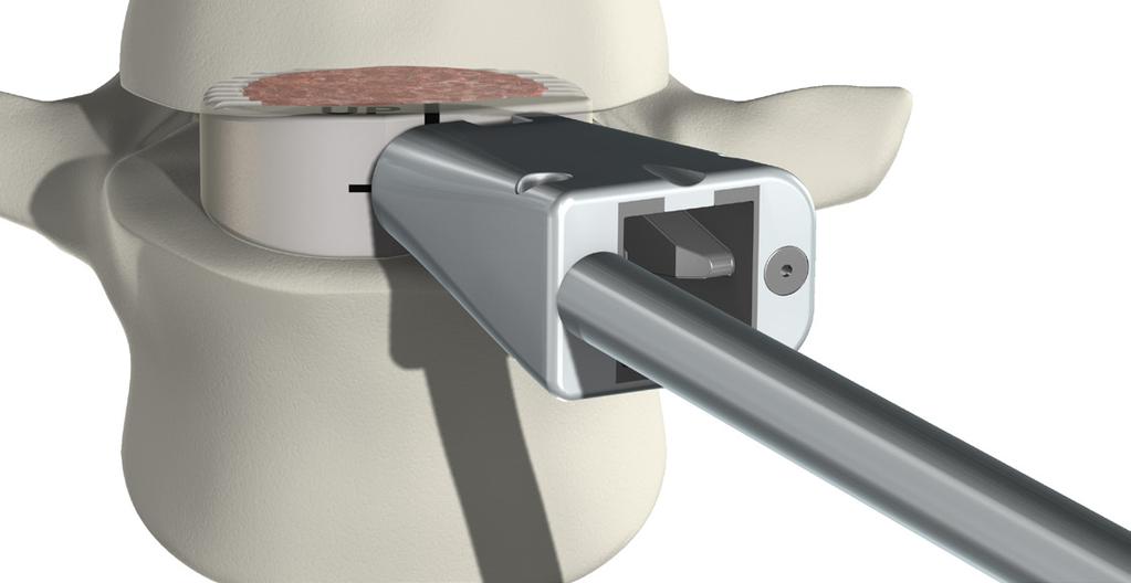
12 SURGICAL TECHNIQUE ROI-A Step 4 Load Bone Graft Place the ROI-A Implant Holder (IR 9280 R) onto the anterior face of the Implant. For oblique,* attach the Implant Holder to the anterolateral face of the implant. First insert the angled pin into the smooth hole. Then insert the threaded rod into the threaded hole. The laser line indicates the threaded hole. Screw the Threaded Rod by tightening the knob at the end of the Implant Holder by hand. As the distance closes between the knob and the Implant Holder, audible clicks can be heard as the ball detent engages the grooves on the knob. It is important to firmly secure the implant to the holder. The connection is secure when: Without over-tightening,** there is no toggle in the connection. There is no visible gap between the Knob and the Handle. Threaded rod Horizontal laser line Angled pin *Note: The Implant Holder must be flipped to accommodate attachment to oblique implant. **Note: Overtightening could strip the PEEK threads and weaken the implant to Holder connection. Median Oblique Knob
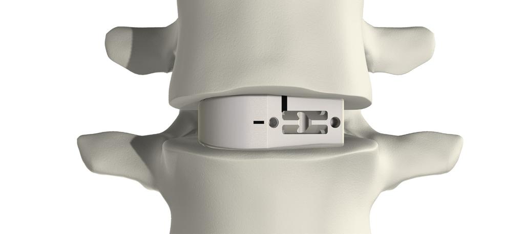
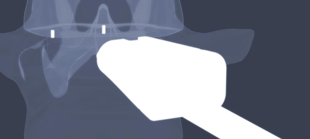
13 Step 5 Implant Cage Prior to implant insertion, assess bone quality. Sclerotic bone may make advancing the VerteBRIDGE plates difficult. A Curette or Burr can be used to prepare the endplates where the plates will enter the vertebrae. Median Implant Insertion Insert Implant directly in the plane of the disc without moving or tilting the Holder side-to-side or up-and-down. Gently mallet the end of the Implant Holder as necessary. Oblique Implant Insertion The ROI-A Oblique requires a specific superior-inferior implant orientation for insertion. The following describes cage orientation for insertion on the patient s left, the more common approach. The UP and laser line marked on the superior and anterior implant face indicate the superior side of the Implant for insertion. The Holder Shaft and Handle will be median; plate insertion and impaction will occur laterally. When inserted properly, the teeth of the cage run parallel to the frontal plane. Implantation with the cage in this position ensure the lordosis slopes correctly anterior to posterior. Insert the Implant at a 25 angle to midline without moving or tilting the Holder side-to-side or up-and-down. The 25 angle can be identified using the ROI-A level (IR 9407 R). Slip the horizontal level into the hole in the Handle of the Holder until the clip is flush. The Holder is at 25 when the level is parallel to the frontal plane of the patient. Note: Assess implant depth and rotation under fluoroscopy. Tantalum markers are located 1mm from the implant edges for positioning reference. When the Implant is in the proper alignment, the two rotational markers will be aligned in the lateral view. Once Implant is positioned between vertebrae, do not try to reposition the implant by rotating the Holder. Instead, remove the Implant completely, confirm the Implant Holder connection is sound, and reinsert the Implant into the desired position


14 SURGICAL TECHNIQUE ROI-A Implant Cage Median Oblique
, or Long (IR2007T).")


.")


15 Step 6 Insert First Plate and Advance Select Plate Select the VerteBRIDGE plate length: Short (IR2009T), Medium (IR2008T), or Long (IR2007T). Plate sizing recommendations: The Short Plate cannot be used with 16 or 18mm implants. Consider using a Short or Medium Plate on patients with small anatomy. At S1 consider the sacrum and the plate s anterior curves when seated in the cage; a shorter plate may be required to avoid penetration of the anterior wall of the sacrum For multi-level procedures: Confirm the central vertebra can accommodate the plate lengths selected. (Refer to table on page 19 for plate vertebrae penetration). It is possible to use a Long Plate on the most superior and inferior vertebral bodies, while using a Short or Medium Plate on the shared, central vertebra. The superior implant may be placed slightly posterior in reference to the inferior cage to avoid plate paths crossing. S M L Plate Loading Notes: The plate paths cross inside the Implant Holder; load the inferior plate into the superior slot and vice versa. The concave surface of the plate will always face the mid-plane of the Holder. The plate is loaded correctly when it drops completely into the Holder. Load First Plate Insert first plate using the Plate Holder (IR9203R) into a slot on the Implant Holder. By default, load the Plate into the superior slot for the inferior vertebral body first, unless anatomy dictates otherwise. CAUTION: Only load one plate at a time


16 SURGICAL TECHNIQUE ROI-A Insert First Plate and Advance Keep Implant Holder in the Plane of the Disc During impaction of the plates, keep the Holder directly in the plane of the disc; avoid tilting the Holder left-to-right or up-and-down. Do not use the Holder as leverage to move the vertebral bodies during cage or plate insertion. Up Right Median Left Down CAUTION: Toggling the Holder during plate insertion can stress the implant to Holder connection. Advance First Plate Oblique Once the position of the implant is optimal, use the Short Plate Impactor (IR9432R) to impact the plate: Confirm a notch in the Implant Holder knob is aligned with the notch in the Implant Holder handle. If not, the Plate Impactor cannot be loaded. Prior to malleting, insert the Impactor using thumb pressure to advance the plate into the implant until it makes contact with bone. After impaction, confirm the underside of the Plate Impactor collar makes contact with the body of the Implant Holder. This assures the plate has advanced completely. If not flush, the first plate may not lock properly and the second plate may not advance.
 to lock the first plate in place.")
17 Step 7 Lock Plate Verify First Plate Position Take a lateral fluoroscopic image to ensure proper implant and plate position. Lock First Plate Once position is confirmed, use the Plate Impactor (IR9431R) to lock the first plate in place. Plate has advanced completely when the underside of the Plate Impactor collar is flush with the body of the Implant Holder. Do not proceed to the second plate insertion until proper placement of the device and first plate is confirmed via fluoroscopy


18 SURGICAL TECHNIQUE ROI-A Step 8 Insert Second Plate and Repeat Load, Advance, and Lock Second Plate Insert the second plate into the opposite slot of the Implant Holder using the Plate Holder. Confirm proper plate alignment by first advancing the plate by hand into the implant using the Impactor. Fully advance the second plate with the Short Plate Impactor. Confirm position under fluoroscopy and then final lock the plate using the Plate Impactor, as described previously. The placement of both plates locks the implant in place and secures the implant between the vertebrae. Median Oblique


 Plate Height (w/ H14) Plate Height")
19 Step 9 Remove Inserter Unlocking Key After both plates are locked and the Plate Impactor is removed, the ROI-A Unlocking Key (IR9434R) can be used to help disconnect the implant from the Implant Holder.* Aligning the two tabs with the notches on the Implant Holder, slip the Unlocking Key over the knob at the end of the handle and turn counter-clockwise. *Note: Do not use the Unlocking Key to screw the cage to the Holder. Plate Penetration into Vertebrae Plate height Anterior height (H) Plate Reference Size Plate Height (w/ H10) Plate Height (w/ H12) Plate Height (w/ H14) Plate Height (w/ H16) Plate Height (w/ H18) IR2009T S N/A N/A IR2008T M IR2007T L


20 SURGICAL TECHNIQUE ROI-A Step 10 Confirm with Fluoroscopy Optional Confirm Final Lock of each Plate Use the Final Plate Impactor (IR9202R) to confirm the final lock of the plates. The radius of the plate end will remain slightly proud of the implant face even after use of the Final Plate Impactor. For each plate, match the groove in the Impactor to the anterior edge of the plate, then mallet the Impactor. The Final Plate Impactor should be used only after advancing the plates with the Plate Impactor as shown on page 16. CAUTION: It is VERY IMPORTANT to confirm final locking of both plates to ensure full impaction. Median Oblique


21 Assess Final Position Take final lateral and anterior-posterior fluoroscopic images to: Confirm position of the plates. Use the Final Plate Impactor to advance the plates if needed. Assess implant position. CAUTION: In cases of spondylolisthesis or vertebral instability, the ROI-A implant with VerteBRIDGE plating should be augmented with adequate posterior pedicle screw fixation and/or anterior plating. Median Median Oblique Oblique Plates need advancing. Approximately 2.5mm of space indicates proper position. Plate needs advancing. Approximately 2.5mm of space indicates proper position Final Fluoroscopy of Proper Placement 20-21


22 SURGICAL TECHNIQUE ROI-A Step 11 Cage removal Remove Plates When removal or revision is indicated, care should be taken to study radiographic images. Make note of: Implant position, which can affect optimum surgical approach. The presence of scar tissue, which can make exposure more challenging than in the un-operated spine. The position of supplemental fixation. Start the explant process with the removal of the plates. To remove the plates, portions of the anterior face of the PEEK implant must be taken out with an Osteotome or Burr. On the below illustrations, the diagonal stripes show the PEEK that must be removed until the plates are visible. Once visible, remove each plate with the Anchoring Plate Hook (IR9288R) by engaging the removal hole on the plate. Pull each plate out along the same path as its curvature. Median Oblique Removal areas After removal Removal areas After removal Remove Implant Plate showing removal hole Plate curvature Use a Kocher to remove the implant anteriorly. If the implant cannot be easily removed, a Cobb Elevator or Osteotome should be used to loosen the bone to implant interface.
23 Device Description and Use Guidelines Device Description The ROI-A implants are cylinder shaped blocks in a variety of footprints, heights, and lordosis angles. The shape of the ROI-A allows for a large implant (length and width) to be used allowing for more surface area contact. The ROI-A Implant System is offered in a closed graft space design. The superior and inferior surfaces of the devices have a pattern of teeth to provide increased stability and to prevent movement of the implants. The ROI-A Implant System is intended to be implanted singularly via an anterior approach and is intended to be used with autologous bone graft. The devices must be used with supplemental internal fixation. The ROI-A Implant System has been designed to be compatible with optional supplemental fixation specific for the system. The VerteBRIDGE Plates are available to be used to affix the ROI-A implant to the underlying vertebral bone and to specifically allow for the option of a stand-alone construct. Additional or other supplemental fixation may be used, as patient needs dictate. The materials used in the manufacturing of the ROI-A implants are (radiolucent) PEEK-Optima LT1 and tantalum alloy radiological position markers. The ROI-A Implant System VerteBRIDGE Plates are manufactured from surgical titanium (Ti6A14V ELI), which complies with ASTM F136. Instruments used to implant the ROI-A Implant System are made of medical grade stainless steel. Contraindications Presence of fever or acute, chronic, systemic, or localized infection. Metal sensitivity or allergies to the implant materials, documented or suspected. Severe osteopenia. Pregnancy. Prior fusion at the level(s) to be treated. Patients unwilling or unable to follow post-operative care instructions. Other medical risks, anesthetics risks, or surgical conditions which would preclude the potential benefit of spinal implant surgery. Any condition not described in the indications for use
24 SURGICAL TECHNIQUE ROI-A Device Description and Use Guidelines Precautions Being a technically demanding procedure presenting a risk of serious injury to the patient, the implantation of intervertebral body fusion devices or partial vertebral body replacement devices should be performed only by experienced spine surgeons with specific training in the use of this system and who have knowledge of the present instruction for use. The surgeon should consider the location of the implantation, the weight of the patient, the patient s activity level or general conditions, and any other factor which may have an impact on the performance of the system. Patients who smoke have been shown to have an increased risk of non-unions. Such patients should be advised of this fact and warned of the potential consequences. If the patient is involved in an occupation or activity which applies inordinate stress upon the implant (e.g., substantial walking, running, lifting of significant loads, or muscle strain), resultant forces can cause failure of the device. In some cases, progression of degenerative disease may also be so advanced at the time of implantation that they may substantially decrease the expected useful life of the device. In such cases, orthopedic devices may be considered only as a delaying technique or to provide temporary relief. Before clinical use, the surgeon should thoroughly understand all aspects of the surgical procedure and limitations of the system. This device is recommended for use only by surgeons familiar with pre-operative and surgical techniques, cautions and potential risks associated with spinal surgery. Knowledge of surgical techniques, proper reduction, selection and placement of implants, and pre- and post-operative patient management are considerations essential to a successful surgical outcome. Patients should be instructed in detail about the limitations of the implants, including but not limited to the impact of excessive loading through patient weight or activity, and should be taught to govern their activities accordingly. Appropriate selection, placement, and fixation of the spinal system components are critical factors which affect implant service life. Accordingly, strict adherence to the indications, contraindications, precautions, and warnings for this product is essential to potentially maximize service life. (Note: While proper implant selection can minimize risks, the size and shape of human bones present limitations on the size, shape, and strength of implants.) Supplemental internal fixation is required when using the ROI-A system. The VerteBRIDGE Plate system is available for use with ROI-A and is the supplemental fixation available for use in situations where a stand-alone construct is appropriate. The system may be augmented with additional supplemental fixation, as needed and determined by the user. The instructions for use for any additional supplemental fixation system(s) should be followed according to the manufacturer s guidelines. Care must be taken to protect the components from being marred, nicked, or notched as a result of a contact with metal or abrasive objects. Alterations will produce defects in surface finish and internal stresses which may become the focal point for eventual breakage of the implant. Inspection and trial assembly are recommended prior to surgery to determine if the instruments have been damaged during storage or prior procedures. Sale of this product is restricted to physicians.
25 Warnings Risks associated with general surgery, orthopedic surgery, and the use of general anesthesia should be explained to the patient prior to surgery. It is also recommended that the advantages and disadvantages of surgery, the implants, as well as alternative treatment methods be explained to the patient. Potential risks associated with the use of this system, which may require additional surgery, include device component failure (bending, loosening, or fracture), loss of fixation, non-union, fracture of the vertebra, neurological injury, vascular or visceral injury, neurological complications, overdistraction, trauma to nerve root or dura, incorrect implant positioning, implant migration, pseudoarthrosis, disc height loss (impaction of implant into vertebral endplates), allergy or inflammation, general adverse effects related to surgical procedures (e.g. anesthesia, infection), subsidence, or expulsion. The device can break if it is subjected to increased loading associated with delayed union or non-union. If healing is delayed or does not occur, the implant could eventually break due to material fatigue. Factors such as the patient weight, activity level, and compliance to weight bearing or load bearing instructions, have an effect in the stresses to which the implant may be subjected, and may effect the longevity of the implant. Patients with previous spinal surgery at the level(s) to be treated may have different clinical outcomes compared to those without a previous surgery. Discard all damaged or mishandled implants. Under no circumstances may the implants be re-used. Although the device may appear intact on removal, internal modification due to the stress and strains placed on it or small defects may exist which may lead to fracture of the implant. Implants removed from a patient that contact bodily tissues or fluids should never be reused at risk of contamination of the patient. Mixing Metal: Some degree of corrosion occurs on all implanted metal and alloys. Contact of dissimilar metals (e.g. stainless steels and titanium), however, may accelerate this corrosion process. The presence of corrosion may accelerate fatigue fracture of implants and the amount of metal compounds released into the body system may also increase. Internal fixation devices such as rods, connectors, screws, hooks, etc, which come into contact with other metal objects must be made from like or compatible metals. This is an important consideration when using supplemental fixation, as required by the indications for use of the System. Because different manufacturers employ different materials, varying tolerances, manufacturing specifications, and differing design parameters, components of the ROI-A System should not be used in conjunction with components from any other manufacturer s implant systems. Any such use will negate the responsibility of LDR Spine USA for the performance of the resulting mixed component implant. Any decision by a surgeon to remove the implanted device should take into consideration such factors as the risk to the patient of the additional surgical procedure as well as the difficulty of removal. Implant removal should be followed by adequate post-operative management to avoid fracture
26 ROI-A ALIF CAGE
27
28 LDR Spine USA, Inc. All rights reserved. United States Research Boulevard Suite 200 Austin, Texas France Hôtel de bureau 1 4, rue Gustave Eiffel Rosières Près Troyes, FRANCE +33 (0) China Unit 06, Level 19, Building A, Beijing Global Trade Center #36 North Third Ring Road East, Dongcheng District, Beijing, China, Brazil Av. Pereira Barreto, º Floor Room 192 to 196 Torre Sul-Bairro Paraíso Santo André / São Paulo-Brazil CEP LDR, LDR Spine, LDR Médical, a passion for innovation, Avenue, BF+, BF+(Ph), Bi-Pack, C-Plate, Easyspine, InterBRIDGE, Laminotome, L90, MC+, Mobi, Mobi-C, Mobi-L, Mobidisc, ROI, ROI-A, ROI-C, ROI-MC+, ROI-T, SpineTune and VerteBRIDGE are trademarks or registered trademarks of LDR Holding Corporation or its affiliates in France, the United States, and other countries. REF: IR-A ST 10 REV A
ROI-A Oblique. ertebridge PLATING TECHNOLOGY
 surgical technique ROI-A Oblique ALIF CAGE with ertebridge PLATING TECHNOLOGY Surgical Technique ROI-A Oblique ALIF CAGE Table of Contents Patient positioning and oblique surgical approach... Discectomy
SURGICAL TECHNIQUE ROI-T TM TLIF INTERSOMATIC IMPLANT TRANS-FORAMINAL APPROACH
 TLIF INTERSOMATIC IMPLANT TRANS-FORAMINAL APPROACH Table of Contents page Step 1 - Articular resection.................................................................................. 3 Step 2 - Pedicle
surgical technique ROI-T
 surgical technique ROI-T TLIF CAGE Surgical Technique ROI-T TLIF cage Table of Contents Approach and facet/pedicle preparation... 3 Controlled distraction... 4 Discectomy and endplate preparation... 6
nva Anterior Lumbar Interbody Fusion System
 nva Anterior Lumbar Interbody Fusion System 1 IMPORTANT INFORMATION FOR PHYSICIANS, SURGEONS, AND/OR STAFF The nv a, nv p, and nv t are an intervertebral body fusion device used in the lumbar spine following
nvp Posterior Lumbar Interbody Fusion System
 nvp Posterior Lumbar Interbody Fusion System 1 IMPORTANT INFORMATION FOR PHYSICIANS, SURGEONS, AND/OR STAFF The nv a, nv p, and nv t are an intervertebral body fusion device used in the lumbar spine following
Thoracolumbar Solutions ROI-A. ALIF Cage. Surgical Technique Guide
 Thoracolumbar Solutions ROI-A ALIF Cage Surgical Technique Guide 2 ROI-A ALIF Cage Surgical Technique Featuring VerteBRIDGE Plating Technology ROI-A ALIF Cage Surgical Technique Guide 3 TABLE OF CONTENTS
nvt Transforaminal Lumbar Interbody Fusion System
 nvt Transforaminal Lumbar Interbody Fusion System 1 IMPORTANT INFORMATION FOR PHYSICIANS, SURGEONS, AND/OR STAFF The nv a, nv p, and nv t are an intervertebral body fusion device used in the lumbar spine
SURGICAL TECHNIQUE ROI-C TM ANTERIOR CERVICAL CAGE
 SURGICAL TECHNIQUE ROI-C TM ANTERIOR CERVICAL CAGE SURGICAL TECHNIQUE ROI-C TM Table of Contents page 1 - Disc location............................................................................................
EXACTECH SPINE. Operative Technique. Cervical Spacer System. Surgeon focused. Patient driven. TM
 EXACTECH SPINE Operative Technique Cervical Spacer System Surgeon focused. Patient driven. TM ACAPELLA ONE Acapella One Cervical Spacer System is an anterior cervical discectomy and fusion device with
SURGICAL TECHNIQUE MODULAR CERVICAL CAGE
 MODULAR CERVICAL CAGE Table of Contents Surgical approach to the disc................................................................. 3 1 to 2 Sizing of the implant..............................................................................
Mobi-C CERVICAL DISC TWO-LEVEL APPLICATIONS
 Mobi-C CERVICAL DISC Product Brochure Features TWO-LEVEL APPLICATIONS INDICATIONS mobi-c Cervical disc bone sparing two-level indications Ease of insertion mobile bearing Over 17,000 Mobi-C discs have
Cervical Spacer System surgical technique
 Blackhawk TM Cervical Spacer System surgical technique Blackhawk TM The BLACKHAWK Cervical Spacer System is designed to provide biomechanical stabilization as an adjunct to fusion. Spinal fixation should
Alamo T Transforaminal Lumbar Interbody System Surgical Technique
 Transforaminal Lumbar Interbody System Surgical Technique Table of Contents Indications and Device Description.............. 1 Alamo T Implant Features and Instruments...........2 Surgical Technique......................
Alamo C. Cervical Interbody System Surgical Technique. An Alliance Partners Company
 Cervical Interbody System Surgical Technique Table of Contents Indications for Use................................1 Device Description............................... 1 Alamo C Instruments..............................
ROI-C CERVICAL CAGE with
 SURGICAL TECHNIQUE ROI-C CERVICAL CAGE with ertebridge PLATING TECHNOLOGY SURGICAL TECHNIQUE ROI-C CERVICAL CAGE Table of Contents Distraction and Discectomy... 3 Trialing... 4 Implant Insertion Depth
HawkeyeTM Peek. surgical technique
 HawkeyeTM Peek surgical technique Introduction The ChoiceSpine HAWKEYE Vertebral Body Replacement (VBR) System is intended for use in the thoracolumbar spine (T1 - L5) to replace a collapsed, damaged,
Apache Cervical Interbody Fusion Device. Surgical Technique. Page of 13. LC-005 Rev F
 LC-005 Rev F Apache Cervical Interbody Fusion Device Page of 13 Surgical Technique INDICATIONS: When used as an intervertebral body fusion device, the Genesys Spine Interbody Fusion System is indicated
TM TM Surgical Technique
 TM TM Surgical Technique TABLE OF CONTENTS Reli SP Spinous Plating System Overview Device Description Implant Features Indications Instruments Access Instruments Preparation Instruments Insertion Instruments
PILLAR AL. Anterior Lumbar Interbody Fusion (ALIF) and Partial Vertebral Body Replacement (pvbr) PEEK Spacer System OPERATIVE TECHNIQUE
 and Partial Vertebral Body Replacement (pvbr) PEEK Spacer System OPERATIVE TECHNIQUE") PILLAR AL PEEK Spacer System Anterior Lumbar Interbody Fusion (ALIF) and Partial Vertebral Body Replacement (pvbr) OPERATIVE TECHNIQUE Table of Contents 1 INTRODUCTION 2 PRE-OPERATIVE TECHNIQUE 3 OPERATIVE
PILLAR AL PEEK Spacer System Anterior Lumbar Interbody Fusion (ALIF) and Partial Vertebral Body Replacement (pvbr) OPERATIVE TECHNIQUE Table of Contents 1 INTRODUCTION 2 PRE-OPERATIVE TECHNIQUE 3 OPERATIVE
Thoracolumbar Solutions. Avenue T. TLIF Cage. with ertebridge PLATING TECHNOLOGY. Surgical Technique Guide
 Thoracolumbar Solutions Avenue T TLIF Cage with ertebridge PLATING TECHNOLOGY Surgical Technique Guide 2 Avenue T TLIF Cage Surgical Technique VerteBRIDGE Plating is the integrated fixation designed specifically
product overview Implant heights range from 8mm-20mm in 2mm increments, with two lordocic angle options of 6 and 12.
 ETHOS A-Spacer PEEK System Surgical Technique Guide Synchronizing Medical Innovation with Global Markets product overview The SyncMedical Ethos PEEK IBF System is an intervertebral body fusion device for
Posterior Lumbar Interbody Fusion System
 Px Posterior Lumbar Interbody Fusion System Px PEEK INTERBODY FUSION SYSTEM INDICATIONS FOR USE The Innovasis Px PEEK IBF System is an intervertebral body fusion device for use in patients with degenerative
Advantage ALIF. Keith Shevlin Managing Director
 Advantage ALIF Unit 10, 9-11 Myrtle Street, Crows Nest NSW 2065 Keith Shevlin Managing Director keithshevlin@precisionsurgical.com.au Advantage ALIF Introduction & Indications for Use 1 Surgical Technique
Surgical Technique. Apache Anterior Lumbar Interbody Fusion
 Surgical Technique Apache Anterior Lumbar Interbody Fusion 2 Table of Contents Page Preoperative Planning 4 Patient Positioning 4 Disc and Endplate Preparation 4 Distraction/Size Selection 5 Implantation
Cervical Solutions ROI-C. Cervical Cage. with ertebridge PLATING TECHNOLOGY. Surgical Technique Guide
 Cervical Solutions ROI-C Cervical Cage with ertebridge PLATING TECHNOLOGY Surgical Technique Guide 2 ROI-C Cervical Cage Surgical Technique Guide ROI-C featuring VerteBRIDGE plating is a zero-profile,
TABLE OF CONTENTS. ShurFit Anterior Cervical Interbody Fusion (ACIF) System Overview 2. Implant Specifications 3. Instrument Features 4
 System Overview 2. Implant Specifications 3. Instrument Features 4") Surgical Technique TABLE OF CONTENTS ShurFit Anterior Cervical Interbody Fusion (ACIF) System Overview 2 Product Highlights 2 Indications 2 Implant Specifications 3 Instrument Features 4 Surgical Technique
Surgical Technique TABLE OF CONTENTS ShurFit Anterior Cervical Interbody Fusion (ACIF) System Overview 2 Product Highlights 2 Indications 2 Implant Specifications 3 Instrument Features 4 Surgical Technique
Royal Oak IBFD System Surgical Technique Posterior Lumbar Interbody Fusion (PLIF)
") Royal Oak IBFD System Surgical Technique Posterior Lumbar Interbody Fusion (PLIF) Preoperative Planning Preoperative planning is necessary for the correct selection of lumbar interbody fusion devices.
Royal Oak IBFD System Surgical Technique Posterior Lumbar Interbody Fusion (PLIF) Preoperative Planning Preoperative planning is necessary for the correct selection of lumbar interbody fusion devices.
SURGICAL TECHNIQUE MANUAL. InterFuse T
 1 CONTENTS InterFuse T Product Description 3 Indications for Use 3 X-Ray Marker Locations 4 Product Specifications 4 Instrument Set 5 Step 1 Preoperative Planning 8 Patient Positioning 8 Step 2 Disc Removal
Veyron -C Anterior Cervical System Surgical Technique
 Veyron -C Anterior Cervical System Surgical Technique 2 Veyron-C Anterior Cervical System Surgical Technique Veyron-C Anterior Cervical System Surgical Technique Description, Indications & Contraindications...3
Solitaire Anterior Spinal System
 Surgical Technique Solitaire Anterior Spinal System Independent Stabilization for the Anterior Column Available in Titanium and Contents Introduction... Page 1 Design Features... Page 2 Instruments...
Aesculap CeSpace TM PEEK and CeSpace TM XP Spinal Implant System Instructions for Use
 Aesculap CeSpace TM PEEK and CeSpace TM XP Spinal Implant System Instructions for Use Page 1 of 5 Indications for use: When used as a Vertebral Body Replacement Device: The CeSpace PEEK and CeSpace XP
C-THRU Anterior Spinal System
 C-THRU Anterior Spinal System Surgical Technique Manufactured From Contents Introduction... Page 1 Design Features... Page 2 Instruments... Page 3 Surgical Technique... Page 4 Product Information... Page
TABLE OF CONTENTS. Vault C Anterior Cervical Discectomy 2 and Fusion (ACDF) System Overview. Implants 3. Instruments 5. Surgical Technique 10
 System Overview. Implants 3. Instruments 5. Surgical Technique 10") Surgical Technique TABLE OF CONTENTS Vault C Anterior Cervical Discectomy 2 and Fusion (ACDF) System Overview Indications 2 Implants 3 Instruments 5 Surgical Technique 10 1. Preoperative planning 10 2.
Surgical Technique TABLE OF CONTENTS Vault C Anterior Cervical Discectomy 2 and Fusion (ACDF) System Overview Indications 2 Implants 3 Instruments 5 Surgical Technique 10 1. Preoperative planning 10 2.
Zimmer Anterior Buttress Plate System. Surgical Technique
 Zimmer Anterior Buttress Plate System Surgical Technique 2 Zimmer Anterior Buttress Plate System Surgical Technique Zimmer Anterior Buttress Plate System Surgical Technique Description, Indications & Contraindications...
OPERATIVE TECHNIQUE. CONSTRUX Mini PTC. Mini PTC Spacer System
 OPERATIVE TECHNIQUE CONSTRUX Mini PTC Mini PTC Spacer System TABLE OF CONTENTS Introduction 1 Operative Technique 2 Part Numbers 6 Indications For Use 7 INTRODUCTION 1 INTRODUCTION The CONSTRUX Mini PTC
CROSS -FUSE P E E K V B R / I B F SYST E M
 S U R G I C A L T E C H N I Q U E CROSS -FUSE P E E K V B R / I B F SYST E M S U R G I C A L S Y S T E M O V E R V I E W 2 CROSS-FUSE P E E K V B R / I B F S Y S T E M S U R G I C A L T E C H N I Q U E
Table of Contents.
 surgical technique The Ambassador TM Anterior Cervical Plate System is a versatile system of implants and instruments with a variety of sizes to provide optimal anatomic compatibility. The integrated cam
ACP1 CERVICAL PLATE SPINAL SYSTEM SURGICAL TECHNIQUE GUIDE II.
 I. ACP1 CERVICAL PLATE II. SPINAL SYSTEM SURGICAL TECHNIQUE GUIDE I. Introduction The Gold Standard Orthopaedics, LLC ACP1 Spinal System was designed with surgeons to incorporate strength, functionality,
SURGICAL TECHNIQUE. Easyspine PEDICLE SCREW SYSTEM
 SURGICAL TECHNIQUE Easyspine PEDICLE SCREW SYSTEM Easyspine PEDICLE SCREW SYSTEM Designed by leading spine surgeons, Easyspine features a simplified surgical technique and adaptable implants to accommodate
BAK/C Cervical Anterior Interbody Fusion System
 Surgical Technique BAK/C Cervical Anterior Interbody Fusion System The Comfortable Choice for Cervical Fusion BAK/C Cervical Surgical Technique 1 The BAK/C Cervical Fusion System is an alternative to conventional
Surgical Technique. Apache Posterior Lumbar Interbody Fusion Apache Transforaminal Lumbar Interbody Fusion
 Surgical Technique Apache Posterior Lumbar Interbody Fusion Apache Transforaminal Lumbar Interbody Fusion 2 Table of Contents Page Preoperative Planning 4 Patient Positioning 5 Disc Exposure 5 Disc and
ACP. Anterior Cervical Plate System SURGICAL TECHNIQUE
 ACP Anterior Cervical Plate System SURGICAL TECHNIQUE ACP TABLE OF CONTENTS INTRODUCTION 4 INDICATIONS AND CONTRAINDICATIONS 5 WARNINGS AND PRECAUTIONS 6 IMPLANT DESCRIPTION 7 INSTRUMENTS 10 SURGICAL
EFSPINE CERVICAL COMBINED SET DISC PROTHESIS ORGANIZER BOX
 EFSPINE CERVICAL COMBINED SET INSTRUMENTS CERVICAL CAGE & DISC PROTHESIS ORGANIZER BOX Cervical Thoracic Thoraco - Lumbar Sacral EFSPINE CERVICAL COMBINED SET CERVICAL IMPLANTS INTRODUCTION Cervical Disc
CERVICAL MODULAR CAGE
 CERVICAL MODULAR CAGE CERVICAL MODULAR CAGE Modularity and exclusive technical characteristics Anchoring clip Open cage Closed cage Bone substitute (made to measure) Stand-alone and versatile Stability
EIT TLIF Cage. For Natural Bone Ingrowth with EIT Cellular Titanium
 EIT TLIF Cage For Natural Bone Ingrowth with EIT Cellular Titanium EIT TLIF Cage Surgical Technique EIT Cellular Titanium provides active fusion area» ~ 80% porosity» ~ 650 µm diamond pore size» open interconnected
Imola Lateral IBF System Surgical Technique
 Imola Lateral IBF System Surgical Technique IMOLA CIRCUIT TABLE OF CONTENTS Design Rationale Instructions for Use Surgical Technique 1. Table Mounting 2. Surgical Planning & Targeting 3. Access and Preparation
Surgical Technique Manual
 InterFuse S Interbody Fusion System Surgical Technique Manual VERTEBRAL TECHNOLOGIES MS 4043-02 Rev. O Product Overview Introduction The VTI InterFuse S implant is an interbody fusion device that combines
VTI INTERFUSE T SURGICAL TECHNIQUE FORWARD THINKING FOR THE BACK. 1/20
 VTI INTERFUSE T SURGICAL TECHNIQUE FORWARD THINKING FOR THE BACK. 1/20 CONTENTS InterFuse T Product Description Indications for Use X-Ray Marker Locations Product Specifications Instrument Set 3 4 5 STEP
Threshold Pedicular Fixation System Surgical Technique
 Threshold Pedicular Fixation System Surgical Technique Table of Contents Patient Preparation and Positioning... 2 Determining Incision Location... 3 Assembling the Cannulated Awl... 4 Guide Wire Placement...
L-VARLOCK. Posterior Lumbar Cage with adjustable lordosis. S urgical T echnique
 L-VARLOCK Posterior Lumbar Cage with adjustable lordosis S urgical T echnique Introduction Designed and manufactured by KISCO International, L-VARLOCK cages are made of titanium alloy Ti 6AI 4V (standards
InFix. Anterior Lumbar Device. Surgical Technique Guide
 InFix Anterior Lumbar Device Surgical Technique Guide 2 InFix Anterior Lumbar Device Surgical Technique Guide InFix Anterior Lumbar System s modular design is intended to restore lordosis, disc height
OPERATIVE TECHNIQUE. anterior cervical plating system
 OPERATIVE TECHNIQUE 3º anterior cervical plating system Introduction 1 Pre-Operative Technique 2 Oerative Technique 3 Instructions for Use 12 Part Numbers 16 The surgical technique shown is for illustrative
VTI INTERFUSE S SURGICAL TECHNIQUE FORWARD THINKING FOR THE BACK.
 VTI INTERFUSE S SURGICAL TECHNIQUE FORWARD THINKING FOR THE BACK. CONTENTS InterFuse S Product Description Indications for Use X-Ray Marker Locations and Product Specifications Instrument Set 3 4 5-7 STEP
A U X I L I A R Y C O N N E C T O R S Surgical Technique
 A U X I L I A R Y C O N N E C T O R S Surgical Technique AUXILIARY CONNECTORS ISSYS LP Auxiliary Connectors The ISSYS LP auxiliary connectors were designed to provide medial-lateral variability for the
Zimmer Facet Screw System Surgical Technique
 Zimmer Facet Screw System Surgical Technique 2 Zimmer Facet Screw System Surgical Technique Zimmer Facet Screw System Surgical Technique Description, Indications & Contraindications...3 Surgical Technique...4
OPERATIVE TECHNIQUE COVER IMAGE OPTIONAL (DETAIL) IMAGE PEEK PTC PILLAR SA PEEK AND PTC SPACER SYSTEM
 IMAGE PEEK PTC PILLAR SA PEEK AND PTC SPACER SYSTEM") OPERATIVE TECHNIQUE COVER IMAGE OPTIONAL (DETAIL) IMAGE PEEK PTC PILLAR SA PEEK AND PTC SPACER SYSTEM TABLE OF CONTENTS Introduction 1 Operative Technique 2 - Partial Vertebral Body Replacement - Intervertebral
OPERATIVE TECHNIQUE COVER IMAGE OPTIONAL (DETAIL) IMAGE PEEK PTC PILLAR SA PEEK AND PTC SPACER SYSTEM TABLE OF CONTENTS Introduction 1 Operative Technique 2 - Partial Vertebral Body Replacement - Intervertebral
Cervical Solutions. Optio-C Anterior Cervical Plate. with Allograft/Autograft. Surgical Technique Guide
 Cervical Solutions Optio-C Anterior Cervical Plate with Allograft/Autograft Surgical Technique Guide 2 Optio-C Anterior Cervical Plate with Allograft/Autograft Surgical Technique Guide The Optio-C System
Thunderbolt. surgical technique. MIS Pedicle Screw System. Where Nimble and Secure Intersect
 Thunderbolt TM MIS Pedicle Screw System Where Nimble and Secure Intersect surgical technique i www.choicespine.com System Features Dovetail set screw: Minimizes head splay and cross-threading Secure connection
VTI INTERLINK PEDICLE SCREW SYSTEM
 VTI INTERLINK PEDICLE SCREW SYSTEM SURGICAL TECHNIQUE FORWARD THINKING FOR THE BACK. DEVICE DESCRIPTION The VTI InterLink Pedicle Screw System is comprised of polyaxial pedicle screws in various diameters
Royal Oak Cervical Plate System
 Royal Oak Cervical Plate System Manufactured by Nexxt Spine, Inc. Royal Oak Cervical Plate System INTRODUCTION FEATURES AND BENEFITS Table of Contents SURGICAL TECHNIQUE Step 1. Patient Positioning Step
Avenue L Lateral Lumbar Cage. Surgical Technique
 Lateral Lumbar Cage Surgical Technique Lateral Lumbar Cage Indication (United States) The Avenue L Lateral Lumbar Cage system is indicated for intervertebral body fusion of the lumbar spine, from L2 to
INTELLIGENT SPINAL SYSTEM
 INTELLIGENT SPINAL SYSTEM I. Introduction II. Product Specification III. Surgical Technique IV. Ordering Information V. IFU for Lospa IS SPINAL SYSTEM The LOSPA IS spinal system consists of
100 Interpace Parkway Parsippany, NJ
 100 Interpace Parkway Parsippany, NJ 07054 www.biometspine.com 800-526-2579 All trademarks are the property of Biomet, Inc. or one of its subsidiaries, unless otherwise indicated. Rx Only. 2009 EBI, LLC.
TiLock XT Minimally Invasive Surgery (MIS) Pedicle Screw System
 Pedicle Screw System") TiLock XT Minimally Invasive Surgery (MIS) Pedicle Screw System The Genesys Spine TiLock XT Minimally Invasive Surgery (MIS) Pedicle Screw System consists of rods (straight and curved), lock screws, and
TiLock XT Minimally Invasive Surgery (MIS) Pedicle Screw System The Genesys Spine TiLock XT Minimally Invasive Surgery (MIS) Pedicle Screw System consists of rods (straight and curved), lock screws, and
Fusion Device. Surgical Technique. Cervical Interbody Fusion with Trabecular Metal Technology
 TM-S Fusion Device Surgical Technique Cervical Interbody Fusion with Trabecular Metal Technology 2 TM-S Fusion Device Surgical Technique Disclaimer This surgical technique is not intended for use in the
SYNCAGE EVOLUTION. This publication is not intended for distribution in the USA. SURGICAL TECHNIQUE
 SYNCAGE EVOLUTION This publication is not intended for distribution in the USA. SURGICAL TECHNIQUE Image intensifier control Warning This description alone does not provide sufficient background for direct
TiLock 2 Spinal System. Surgical Technique
 TiLock 2 Spinal System Surgical Technique Table of Contents Page Preoperative Planning 4 Pedicle Preparation 5 Probe 5 Tap Pedicle 6 Screw Options 7 Screw Insertion 8 Aligning the Windows 9 Rod Insertion
XRL A modular expandable radiolucent vertebral body replacement system
 XRL A modular expandable radiolucent vertebral body replacement system This publication is not intended for distribution in the USA. SURGICAL TECHNIQUE Table of Contents Introduction XRL 2 AO Spine Principles
Y o u r Id e a s En g i n e e r e d t o Li f e
 ISSYS LP Spinal Fixation System Surgical Guide Y o u r Id e a s En g i n e e r e d t o Li f e In t r o d u c t i o n ISSYS LP Sp i n a l Fixation System The foundation of the ISSYS LP Spinal Fixation System
Technique Guide. T-PAL. Transforaminal posterior atraumatic lumbar spacer system.
 Technique Guide T-PAL. Transforaminal posterior atraumatic lumbar spacer system. Table of Contents Introduction T-PAL 2 AO Principles 4 Indications and Contraindications 5 Surgical Technique Preparation
SURGICAL TECHNIQUE GUIDE TRESTLE. Anterior Cervical Plating System
 SURGICAL TECHNIQUE GUIDE TRESTLE Anterior Cervical Plating System 2 SURGICAL TECHNIQUE GUIDE SURGICAL TECHNIQUE GUIDE System Features Large window enables visualization of graft site and end plates Screw
OPERATIVE TECHNIQUE COVER IMAGE OPTIONAL (DETAIL) IMAGE SKYHAWK. lateral interbody fusion system lateral plate system
 IMAGE SKYHAWK. lateral interbody fusion system lateral plate system") OPERATIVE TECHNIQUE COVER IMAGE OPTIONAL (DETAIL) IMAGE SKYHAWK lateral interbody fusion system lateral plate system TABLE OF CONTENTS Introduction 1 Pre-Operative Technique 2 Operative Technique 3 Part
OPERATIVE TECHNIQUE COVER IMAGE OPTIONAL (DETAIL) IMAGE SKYHAWK lateral interbody fusion system lateral plate system TABLE OF CONTENTS Introduction 1 Pre-Operative Technique 2 Operative Technique 3 Part
Replacement Device A modular expandable radiolucent vertebral body replacement system
 XRL Vertebral Body Replacement Device A modular expandable radiolucent vertebral body replacement system SURGICAL TECHNIQUE TABLE OF CONTENTS Introduction XRL System 2 AO Principles 5 Indications and Contraindications
OPERATIVE TECHNIQUE PTC PEEK FORZA. spacer system
 OPERATIVE TECHNIQUE PTC PEEK FORZA spacer system TABLE OF CONTENTS Introduction 1 Operative Technique 2 Instruments 12 FORZA PEEK Part Numbers 20 FORZA PTC Part Numbers 22 Modular Implant Inserter 24 Disassembly
Cervical Solutions. Optio-C Anterior Cervical PEEK. Interbody System. Surgical Technique Guide
 Cervical Solutions Optio-C Anterior Cervical PEEK Interbody System Surgical Technique Guide 2 Optio-C Anterior Cervical PEEK Interbody System Surgical Technique Guide The Optio-C System provides a zero-profile
X-spine Surgical Technique
 X-spine Surgical Technique The X90 Pedicle Screw System Revolutionary Design and Function This document is intended exclusively for experts in the field, particularly physicians, and is not intended for
SynCage. Surgical Technique. This publication is not intended for distribution in the USA. Instruments and implants approved by the AO Foundation.
 SynCage Surgical Technique This publication is not intended for distribution in the USA. Instruments and implants approved by the AO Foundation. Image intensifier control Warning This description alone
Luminary ALIF. Disc preparation and implant insertion instruments.
 Luminary ALIF. Disc preparation and implant insertion instruments. Technique Guide Instruments and implants approved by the AO Foundation Table of Contents Introduction Luminary ALIF 2 AO Principles 4
MODULAR DESIGN OFFERS FREEDOM OF CHOICE. Surgical Technique
 MODULAR DESIGN OFFERS FREEDOM OF CHOICE Surgical Technique Joint Spine Sports Med MectaLIF Anterior Surgical Technique 2 INDEX 1. INTRODUCTION 4 1.1 Material & Marker 5 2. INDICATIONS 5 3. CONTRAINDICATIONS
TiLock XT Minimally Invasive Surgery (MIS) Pedicle Screw System
 Pedicle Screw System") Minimally Invasive Surgery (MIS) Pedicle Screw System Surgical Technique Guide 2 Minimally Invasive Surgery (MIS) Pedicle Screw System The Genesys Spine Minimally Invasive Surgery (MIS) Pedicle Screw System
Minimally Invasive Surgery (MIS) Pedicle Screw System Surgical Technique Guide 2 Minimally Invasive Surgery (MIS) Pedicle Screw System The Genesys Spine Minimally Invasive Surgery (MIS) Pedicle Screw System
GIZA Surgical Technique
 GIZA Surgical Technique Vertebral Body Replacement System Manufactured by Titanium alloy material provides mechanical integrity during insertion and distraction, x-ray visibility, and biocompatibility*
Zimmer NexGen MIS Tibial Component. Cemented Surgical Technique IMAGE TO COME
 Zimmer NexGen MIS Tibial Component Cemented Surgical Technique IMAGE TO COME Zimmer NexGen MIS Tibial Component Cemented Surgical Technique 1 Zimmer NexGen MIS Tibial Component Cemented Surgical Technique
Synex System TECHNIQUE GUIDE. An expandable vertebral body replacement device
 Synex System TECHNIQUE GUIDE An expandable vertebral body replacement device Original Instruments and Implants of the Association for the Study of Internal Fixation AO ASIF Synex System Overview The Synex
VLIFT System Overview. Vertebral Body Replacement System
 VLIFT System Overview Vertebral Body Replacement System VLIFT System System Description The VLIFT Vertebral Body Replacement System consists of a Distractible In Situ (DIS) implant, which enables the surgeon
ASFORA ANTERIOR CERVICAL PLATE SYSTEM (AACP) SURGICAL PROCEDURE MANUAL
 SURGICAL PROCEDURE MANUAL") ASFORA ANTERIOR CERVICAL PLATE SYSTEM (AACP) SURGICAL PROCEDURE MANUAL Contents: Introduction Indications Contraindications Warnings Precautions Implant Overview Instruments Overview Surgical Technique
ASFORA ANTERIOR CERVICAL PLATE SYSTEM (AACP) SURGICAL PROCEDURE MANUAL Contents: Introduction Indications Contraindications Warnings Precautions Implant Overview Instruments Overview Surgical Technique
Zimmer Trabecular Metal Ankle Interpositional Spacer and Trabecular Metal Ankle Fusion Spacer
 Zimmer Trabecular Metal Ankle Interpositional Spacer and Trabecular Metal Ankle Fusion Spacer Surgical Technique 2 Zimmer Trabecular Metal Ankle Interpositional Spacer and Trabecular Metal Ankle Fusion
Interbody fusion cage for the transforaminal approach. Travios. Surgical Technique
 Interbody fusion cage for the transforaminal approach Travios Surgical Technique Image intensifier control This description alone does not provide sufficient background for direct use of DePuy Synthes
SYNFIX. LR Stand Alone Spacer. Instruments and implants for stand alone anterior lumbar interbody fusion (ALIF). Technique Guide
. Technique Guide") SYNFIX LR Stand Alone Spacer. Instruments and implants for stand alone anterior lumbar interbody fusion (ALIF). Technique Guide Table of Contents Introduction SYNFIX LR Stand Alone Spacer 2 AO Principles
SYNFIX LR Stand Alone Spacer. Instruments and implants for stand alone anterior lumbar interbody fusion (ALIF). Technique Guide Table of Contents Introduction SYNFIX LR Stand Alone Spacer 2 AO Principles
Valencia Pedicle Screw Surgical Technique
 Valencia Pedicle Screw Surgical Technique VALENCIA CIRCUIT TABLE OF CONTENTS Design Rationale Indications for Use Surgical Technique 1. Pedicle Preparation 2. Screw Insertion 3. Rod Placement 4. Locking
PACH PLATE 2 OR 4 HOLE FIXATION
 2 OR 4 HOLE FIXATION The Science of Fusion PACH_v6.indd 1 6/03/2015 7:10 am PACH Plate Design Rationale The PACH Plate has been designed to be used as an anterior or lateral fixation plate for the thoracolumbar,
Thoracolumbar Solutions. Zyston Curve. Interbody Spacer System. Surgical Technique Guide
 Thoracolumbar Solutions Zyston Curve Interbody Spacer System Surgical Technique Guide 2 Zyston Curve Interbody Spacer System Surgical Technique Guide The Zyston Curve Interbody System is designed to optimize
HydraLok. Operative Technique. Polyaxial Pedicle Screw System
 HydraLok Operative Technique Polyaxial Pedicle Screw System Table of Contents Introduction...1 OPERATIVE TECHNIQUE OVERVIEW...2 DETAILED OPERATIVE TECHNIQUE...4 LOCATE AND PREPARE THE PEDICLE...4 PROBE
Cervical Solutions. Alta. ACDF System. Surgical Technique Guide
 Cervical Solutions Alta ACDF System Surgical Technique Guide 2 Alta ACDF System Surgical Technique Guide A comprehensive system to address a continuum of fixation requirements and anatomic demands. Alta
AVS ARIA TM Product Overview
 AVS ARIA TM Product Overview Table of Contents Indication 3 Adaptive Sizing 4-5 Wedge Nose Design 6 Graft Volumes 7 Efficient Fixation 8 Lordotic Descriptions 9 Anatomical Descriptions 10 Visualization
Mobi-C CERVICAL DISC. Surgical Technique
 Mobi-C CERVICAL DISC Surgical Technique TABLE OF CONTENTS Surgery preparation and approach...3 Discectomy and trialing...5 Mobi-C insertion... 11 Removal of PEEK cartridge and position assessment... 16
USS Variable Axis Screw (VAS) System. For posterior fixation of the lumbar spine.
 System. For posterior fixation of the lumbar spine.") USS Variable Axis Screw (VAS) System. For posterior fixation of the lumbar spine. Technique Guide Instruments and implants approved by the AO Foundation Table of Contents Introduction USS Variable Axis
USS Variable Axis Screw (VAS) System. For posterior fixation of the lumbar spine. Technique Guide Instruments and implants approved by the AO Foundation Table of Contents Introduction USS Variable Axis
 Visit our website on www.biotech-medical.com The DLP - Dorso-Lumbar Polyaxial Screw System has been designed to address the pathologies of the thoracolumbar spine. The DLP System contains a wide range
TraXis TLIF Interbody System
 TraXis TLIF Interbody System Surgical Technique Solutions by the people of Zimmer Spine. zimmerspine.com A TLIF that s ahead of the curve. From the people of Zimmer Spine. Minimally Invasive Surgery (MIS)