Zimmer Continuum Acetabular System. Surgical Technique
|
|
|
- Clemence Hodge
- 6 years ago
- Views:
Transcription


1 1 Zimmer Continuum Acetabular System Surgical Technique
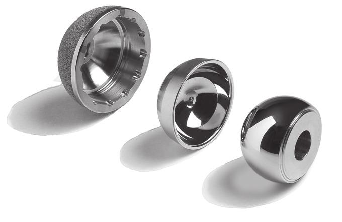
2 2 Zimmer Continuum Acetabular System Surgical Technique Device Description The Continuum Shell is hemispherical in shape with an exterior of Trabecular Metal Material that is bonded to a Tivanium alloy substrate. The Shell has a snap fit locking groove for acceptance of the Vivacit-E Vitamin E Highly Crosslinked Polyethylene Neutral or Elevated Liners and the Longevity Highly Crosslinked Polyethylene Neutral or Elevated Liners. Twelve scallops, equally spaced in 30 increments, included on the Shell face mate with twelve anti-rotation tabs on the Vivacit-E Vitamin E and Longevity Liners. The Shell also has an integrated locking taper mechanism designed to accept Metasul Hard Bearing Liners. Indications/Intended Use Vivacit-E Vitamin E Highly Crosslinked Polyethylene Longevity Highly Crosslinked Polyethylene Liners The system is indicated for primary or revision surgery in skeletally mature individuals for rehabilitating hips damaged as a result of noninflammatory degenerative joint disease (NIDJD) or its composite diagnoses of osteoarthritis, avascular necrosis, protrusio acetabuli, traumatic arthritis, slipped capital epiphysis, fused hip, fracture of the pelvis, and diastrophic variant. The system is intended for use either with or without bone cement in total hip arthroplasty. Metasul Metal-on-Metal Technology Noninflammatory degenerative joint disease (NIDJD) including avascular necrosis, osteoarthritis, post-traumatic arthritis and congenital hip dysplasia and inflammatory joint disease (IJD), e.g. rheumatoid arthritis if bone quality is adequate. Failed previous surgery where pain, deformity, or dysfunction persists. Revision of previously failed hip arthroplasty. Total hip replacements may be considered for younger patients if any unequivocal indication outweighs the risks associated with the age of the patient and modified demands regarding activity and hip joint loading are assured. This includes severely handicapped patients with multiple joint involvement, for whom an immediate need of hip mobility leads to an expectation of significant improvement in the quality of their lives. The system is intended for use either with or without bone cement in total hip arthroplasty.
 of the acetabular cup represents the true hemispherical diameter of the Implant.")
.")


3 Zimmer Continuum Acetabular System Surgical Technique 3 Acetabular Reamer 54mm Reamer has a 54mm O.D. Shell Provisional 54mm Provisional has a 54mm O.D. Acetabular Cup 54mm Continuum Cup has a 54mm O.D. Introduction The labeled outside diameter (O.D.) of the acetabular cup represents the true hemispherical diameter of the Implant. An appropriate undersized reamer must be used to prepare the acetabulum if a press fit condition is desired. The amount of press fit used should be determined at the time of surgery and be based on bone quality. Shell Implants are labeled with the exterior size and a corresponding two letter code (e.g. 56 KK). The matching Liner Implants are identified with the matching letter code and head diameter (e.g. 28 KK, 32 KK, 36 KK, 40 KK). 210mm 200mm 190mm 180mm 170mm 160mm 150mm 140mm 48mm GG CONTINUUM ACETABULAR SYSTEM 20% ENLARGED TEMPLATE 2 48mm 58mm 50mm HH Templating 130mm The primary goal of templating is to estimate the size and position of the acetabular Implant. 120mm 110mm 52mm II 54mm JJ 45 degrees of abduction and 20 degrees of forward flexion is recommended in most cases. Use of the alignment guides with various patient positions is outlined in later sections of the technique. 100mm 90mm 80mm 70mm To increase the accuracy of templating, digital imaging or x-rays with magnification markers should be used. The magnification of the x-rays and the templates should be compared when sizing the Implant. 60mm 50mm 40mm 56mm KK 58mm LL Templating should start with the A/P radiograph. (Fig. 1) 30mm The component should NOT be more medial than the cortyloid notch and should NOT be against the radiographic tear drop. To avoid vertical cup placement a line drawn along the cup template opening should intersect the obturator foramen. 20mm 10mm 0mm NOTE: Head centers are the same for all liner types. NOTE: This is intended to be used as a surgical planning aid and not as a measuring tool (Set of 3) 0905-H02.05ML Printed in USA 2009, 2010 Zimmer, Inc It may be helpful to cross-check the acetabular component size on the lateral radiograph, which can provide a view of the hemispherical subchondral bone. The largest component that meets these requirements should be selected. However, the final decision on component size should be made during surgery, when all aspects of the acetabulum can be fully visualized. Fig. 1 AP Templating View.


4 4 Zimmer Continuum Acetabular System Surgical Technique Surgical Approach The Continuum Cup may be implanted using a variety of standard surgical approaches. Note: While the surgeon s approach may vary, the approach must provide adequate exposure to visualize the entire acetabular rim. Acetabular Preparation Excise the acetabular labrum and remove any large peripheral osteophytes. Excise the ligamentum teres to expose the true floor of the acetabulum. Note: It is important to visualize the entire bony rim of the acetabulum to reduce the likelihood of soft tissue entrapment which may prevent the cup from seating during insertion. Note: The 38mm IT Provisional Sizer is used to assess the size of the reamed cavity. There is no corresponding 38mm Implant. Acetabular Reaming From templating and preoperative planning, determine the desired head position. Start with a smaller reamer and proceed to the next largest reamer in 1-2mm increments. Reaming depth is based on bone quality but usually is completed after bleeding cancellous bone is exposed. Note: Take extra care to avoid eccentric reaming by holding the reamer steady. Apply constant pressure in the recommended final Implant orientation of 45 degrees of abduction and 20 degrees of forward flexion. Fig. 2b Fig. 2c Shell and Provisional Shell Inserter Options Fig. 3 Fig. 2a Caution: Throughout the entire procedure, take care in handling sharp Implants or Instruments. Shell Provisional Insertion and Alignment Proper care must be taken to assess bone quality and to determine the appropriate Implant size and type. You may use either the Straight Shell Inserter (Fig. 2a), Hybrid Offset Shell Inserter (Fig 2b) or the Trilogy Cup Positioner (Fig. 2c) with the appropriate metal cap to Insert the Provisional Shell. The Shell Inserter with Adaptor mating with the Provisional Shell. If using the Straight Shell Inserter or Hybrid Offset Shell Inserter: Place the Shell Inserter Adapter, with or without Rotational Control, onto the tip of either the Straight Shell Inserter or Hybrid Offset Shell Inserter. (Fig. 3) Insert a Ball Head Hex Driver through the window and into the locking Screw at the tip of the Inserter. (Fig. 4) While holding the Shell Provisional in place, securely thread the Locking Screw into the Polar Hole of the Shell Provisional. Attach the Alignment Frame or Gunsight Alignment Guide to the Inserter and tighten the Thumb Screw. Fig. 4 Attaching the Shell Provisional to the Inserter Handle using the Hex-Head Driver.
 The arms on the Guide are used to correctly position the Provisional Shell and/or Implant. See the diagrams for use instructions on the lateral and supine approaches (Pages 16-19).")


5 Zimmer Continuum Acetabular System Surgical Technique 5 Note: The Alignment Support Frame on the Shell Inserter will not be vertical to the floor and should not be used as a positioning guide. (Fig. 5) The arms on the Guide are used to correctly position the Provisional Shell and/or Implant. See the diagrams for use instructions on the lateral and supine approaches (Pages 16-19). With the Shell Provisional in the appropriate alignment, use a mallet to impact the handle of the Inserter. To prevent thread damage, verify that the Locking Screw is fully tightened to the Shell as repetitive impacts could cause the screw to loosen. The Shell Provisional has fenestrations to assess proper cup seating inside the acetabulum. When the Shell Provisional is fully seated, turn the Driver counterclockwise to loosen the attachment Screw on the Inserter. Remove the Inserter. If using the Trilogy Cup Positioner (Fig. 6): Select the appropriate Positioner cap based on shell size. Shells 40-46mm use the Micro Cap (Fig. 7) Shells 48-80mm use the existing Trilogy Cap (Fig. 8) Thread the Shell Provisional onto the Positioner until secure. Rotate the Alignment Connector to achieve desired shell screw hole orientation. Fix the Alignment Connector into place by tightening the Locking Nut. Using the small slaphammer on their shafts, impact one of the following Alignment guides in the alignment connector to engage onto the taper: Lateral A-Frame Alignment Guide Supine A-Frame Alignment Guide Lateral Gunsight Alignment Guide Supine Gunsight Alignment Guide If using Lateral or Supine Gunsight Alignment Guide, insert Alignment Rod into appropriate hole (Left or Right). See the diagrams for use instructions on the lateral and supine approaches (Pages 16-19). With the Shell Provisional in the appropriate alignment, use a mallet to impact the handle of the Positioner. When the Shell Provisional is fully seated unscrew the Positioner from the Shell Provisional. Thread the Locking Screw into the Polar Hole of the Shell Provisional. Fig. 5 Do not use the support frame to align the Provisional Shell or Shell Implant. Alignment Connector Fig. 6 Trilogy Cup Positioner Fig. 7 Fig. 8 Locking Nut Trilogy Micro Cap Trilogy Cap
 and one with a Locking Screw permanently affixed within the Provisional Liner. (Fig. 10) Note: The Permanently Affixed Locking Screw should not be removed.")
.")
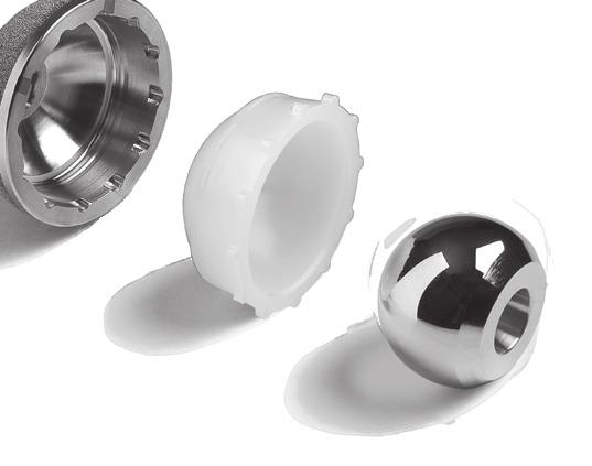
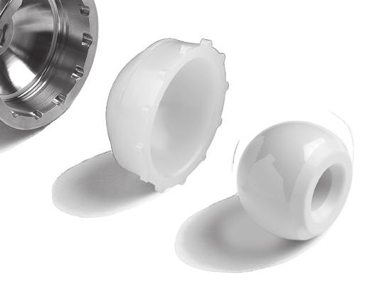
6 6 Zimmer Continuum Acetabular System Surgical Technique Provisional Liner Insertion Inserting the Provisional Liner There are two different Provisional Liners. One with a Locking Screw that is independent of the Provisional Liner (Fig. 9) and one with a Locking Screw permanently affixed within the Provisional Liner. (Fig. 10) Note: The Permanently Affixed Locking Screw should not be removed. Select the Provisional Liner size that matches the selected Provisional Shell. The selected Shell Provisional will be identified through a size and a two letter code (e.g. 50 HH). There are different inner diameter Implant sizes available for each Shell size. The Provisional Liner will be identified by letter code matching the Shell diameter and desired inner diameter (e.g. 32 HH). Both types of Provisional Liners are inserted the same way; however, the Provisional Liner with Independent Locking Screw must first be assembled by using a Hex-head Driver to insert the Provisional Locking Screw through the Polar Hole of the Provisional Liner. The Provisional Locking Screw will have a silver ring. For both types of Provisional Liners, the smallest Neutral Provisional Liners in head sizes 32mm, 36mm and 40mm (32 FF, 36 HH and 40 JJ) do not have a Locking Screw and seat with a peg feature. Insert the Provisional Liner by hand into the Provisional Shell. Implant Insertion If using the Straight Shell Inserter or Hybrid Offset Inserter: There are two Adapters for the Inserter Handles. The Adapter with Rotational Control locks to prevent the Implant from rotating freely on the Inserter handle. If this Adapter is used with a Cluster Hole Shell, the dark etch on the Adapter should be in line with the alignment frame on the Inserter to allow for Cluster Hole placement in the posterior superior and posterior inferior quadrants. Note: The Shell Inserter Adapter without Rotational Control will allow the Implant to rotate freely on the Inserter. Use this Adapter when it is necessary to position the Screw Holes in a specific location within the acetabulum. The Shell Inserter Adapter with Rotational Control has two pins that will fit into slots at the tip of the Inserter. These pins are not found on the Shell Inserter Adapter without Rotational Control. To insert the Implant, follow the same procedure described previously for inserting provisional shells using the Straight Shell Inserter or Hybrid Offset Shell Inserter. If using the Trilogy Cup Positioner: The Trilogy Cup Positioner does not have rotational control. Control of Implant orientation is at the discretion of the surgeon and can be adjusted by rotating the position of the Alignment Connector relative to the shaft of the Trilogy Cup Positioner. To insert the Implant, follow the same procedure described previously for inserting provisional shells using the Trilogy Cup Positioner. If applicable, ensure that the anti-rotation tabs of the Provisional Liner are engaged in the Shell Provisional scallops. Note: Do not impact the Provisional Liner as damage may occur. Thread the Locking Screw into the Polar Hole of the Shell Provisional. Trial Range of Motion Insert a head/neck Provisional onto the Implanted Stem or Rasp Cone Provisional and perform a trial reduction. Check for stability and range of motion. Remove the Provisional components. Note: Refer to Zimmer s product compatibility website, to determine compatibility among all selected components. Fig. 9 Provisional Liner with Independent Locking Screw Fig. 10 Provisional Liner with Permanently Affixed Locking Screw


7 Zimmer Continuum Acetabular System Surgical Technique 7 With the Implant in the appropriate position and alignment, use a mallet to impact the handle of the Inserter. When the Implant is fully seated, turn the Driver counterclockwise to loosen the Attachment Screw on the Inserter. Remove the Inserter. Note: The impact required to seat the Implant is dictated by the bone quality. Posterior Superior Note: Do not lever on the Shell or the Shell Inserter to reposition the Implant, as damage may occur to the threads or inner diameter of the Shell. Anterior Superior Posterior Inferior Note: The potential for neurologic and vascular injury can be minimized if the posterior quadrants are used for transacetabular screw placement.* The Shell should be positioned to allow screw placement in the posterior superior and/or posterior inferior quadrants of the acetabulum. (Fig. 11) The Continuum Screw Holes are located closer to the Polar region as compared to the Trabecular Metal Shell. Fig. 11 Anterior Inferior Correct location for Screw placement in shaded regions. * Wasielewski RC, Cooperstein LA, Kruger MP, Rubash HE. Acetabular anatomy and the transacetabular fixation of screws in total hip arthroplasty. J Bone Joint Surg. 1990:72- A(4);

 The screw angle may vary by as much as 33 degrees (inclusive). The effective lengths of the three drill bits available are 15mm, 30mm and 45mm.")

8 8 Zimmer Continuum Acetabular System Surgical Technique Screw Insertion If Screw placement is desired: Carefully following these steps for Screw insertion can help to minimize Screw push-through or torque-out after initial implantation. Drill a pilot hole, using either a Modular or One-Piece Flex Drill. If using the Modular Flex Drill attach the selected bit using the Hex Wrench. (Fig. 12) Check the bit to ensure that it is not dull. Position the Adjustable Drill Guide and Flex Drill into the selected Screw Hole. (Fig. 13) The screw angle may vary by as much as 33 degrees (inclusive). The effective lengths of the three drill bits available are 15mm, 30mm and 45mm. Upon seating of the drill bit completely into the drill guide, the drilled holes will correspond to the effective length of the drill bit. For sclerotic bone, an option may be to tap the Screw hole. Attach the Modular Tap Shaft into the Modular Handle by pulling back on the snap-lock collet and aligning the hole in the shaft with the etched line on the collet. Attach the appropriate Tap to the Modular Tap Shaft. Bicortical tapping the entire depth should be done with care by turning the Tap Handle clockwise. Fig. 12 Attaching the bit to the Flex Drill with the Hex Wrench. Set Screw Removal To loosen the set screw, turn it counterclockwise until the thread fully disengages from the flexible shaft. The set screw will be captured in the flexible drill shaft between the threads and the screw stop. (Fig. 14) Alternatively, the set screw can be removed by turning it clockwise to fully disengage the set screw and placing it into the set screw holder in the instrument tray. After either loosening or removing the set screw, remove the drill bit. Fig. 13 Inserting the Adjustable Drill Guide and Modular Flex Shaft into the Shell. Fig. 14 Loosening the Flex Drill set screw.
 Select the appropriate length Trilogy Screw. Use a Screwdriver to insert it into the selected Screw hole. Screws cannot be inserted into the Polar Hole at the dome of the Shell. (Fig.")


9 Zimmer Continuum Acetabular System Surgical Technique 9 After drilling the pilot or tapping the Screw hole: Use the Depth Gauge to measure the depth of the Screw hole. (Fig. 15) Select the appropriate length Trilogy Screw. Use a Screwdriver to insert it into the selected Screw hole. Screws cannot be inserted into the Polar Hole at the dome of the Shell. (Fig. 16) Note: Countersink screw heads below the interior surface of the shell to prevent the liner from contacting the screw head. Ensure that the screw heads are properly seated. Screw heads that protrude in to the inner shell can prevent adequate seating of the liner. Use a 3.2mm diameter drill prior to insertion of the 4.5 or 6.5mm diameter screws. Avoid penetration beyond the inner cortex of the pelvis when drilling holes and inserting screws. (Fig. 17) Place additional Screws as necessary. Carefully evaluate the bone quality, and avoid over-tightening the Screws. To remove a Screw, engage the Screw with a Hex Head Driver and turn it counterclockwise. Fig. 15 Using the Depth Gauge to measure the screw hole depth. Warning: Avoid Screw placement through the Shell into the anterior inferior and anterior superior quadrants of the acetabulum to prevent injury to the neurovascular structures. Fig. 16 Using a screwdriver to insert the screws. Fig. 17 Checking to ensure that the screws are properly seated.

 Note: The Screw Hole Plugs cannot be used with 40mm and 42mm shells as the screw holes in these shells were not designed to accept a Screw Hole Plug.")
10 10 Zimmer Continuum Acetabular System Surgical Technique Optional Screw Hole Plugs Screw Hole Plug Place a Screw Hole Plug on the appropriate Hex Head Driver to ensure it is perpendicular to the Screw Hole Plug. Align the Plug and Screw Hole until the Plug clearly drops into the Hole. Note: The Screw Hole Plugs are slightly oval in shape and engage by providing an interference fit. To lock the Plug, turn it in either direction. The Plug will lock in place with a partial turn. To remove the Hole Plug, turn in the opposite direction to release the interference fit. (Fig. 18) Note: The Screw Hole Plugs cannot be used with 40mm and 42mm shells as the screw holes in these shells were not designed to accept a Screw Hole Plug. Provisional Liner Positioning Clean and dry the cup with a sterile cloth, wipe or sponge to remove third-body debris. Clear all soft tissue from around the perimeter of the Shell and assess visualization. The smallest Neutral Provisional Liners in head sizes 32 mm, 36 mm and 40 mm (32 FF, 36 HH and 40 JJ) do not have a Locking Screw and seat with a peg feature. Fig. 18 Screw Hole Plug insertion. Insert the Provisional Liner by hand into the Shell. If applicable, ensure that the anti-rotation tabs of the Provisional Liner are engaged in the Shell scallops. Note: Do not impact the Provisional Liner as damage may occur. Thread the Locking Screw into the Polar Hole of the Shell. Optional Dome Hole Plugs Insert a Plug into the Polar Hole and thread it into place. When correctly inserted the Plug will be slightly inset relative to the interior surface of the Shell, but it will be slightly proud within the recessed square at the pole. (Fig. 19) Take care not to overtighten the Dome Hole Plug. Fig. 19 Correct seating of the Polar Hole Plug.


11 Zimmer Continuum Acetabular System Surgical Technique 11 Liner Insertion Instrument Metasul Liners Prior to inserting the Metasul Liner, ensure the interior of the Shell, the Liner and Liner Insertion Instrument are clean and dry. Also inspect the Shell to ensure that no damage occurred to the taper, Dome Hole Plugs or Screw Hole Plugs. Metasul Liners can be inserted by hand or using the Liner Insertion Instrument. If using the Liner Insertion Instrument, follow these assembly instructions: Insert the suction tip onto the shaft of the Instrument up to the etch line. Ensure that the shaft is bottomed out in the suction tip. Saline or water can be used to lubricate the suction cup for easier assembly. Engage Liner and Liner Insertion Instrument by depressing the suction cup in the Liner. Insert the Liner into the Shell. Remove the Liner Insertion Instrument by lifting up on the interior rod to release the vacuum. (Fig. 20) Note: Do not impact the Liner Insertion Instrument. This is indicated on the Instrument using the following symbol. Fig. 20 Disengaging the Liner Insertion Instrument. Select the correct size Hard Bearing Rim Impactor or Dome Impactor which will match the Implant head size (28mm, 32mm, 36mm or 40mm). Attach the Hard Bearing Rim Impactor or Dome Impactor to either the straight or curved Universal Handle by aligning the pins on the Universal Handle with the keyhole slot on the underside of the Impactor. (Fig. 21) Push the Impactor onto the handle and twist it in either direction to lock it in place. Fig. 21 Dome Impactor.
 This will decrease the likelihood of incorrect Liner seating. Palpate the Liner to ensure it is uniformly seated prior to impaction.")
 Note: Larger sized Metasul Liners may be difficult to handle and assemble given their greater weight. Fig.")
12 12 Zimmer Continuum Acetabular System Surgical Technique Center the Metasul Liner by rocking the Universal Handle with the attached Hard Bearing Rim Impactor prior to impaction. (Fig. 22) This will decrease the likelihood of incorrect Liner seating. Palpate the Liner to ensure it is uniformly seated prior to impaction. Place the Hard Bearing Rim Impactor or Dome Impactor on the Liner. Firmly strike the Universal Handle once with a mallet to fully seat the Liner. Verify that the Liner is properly inserted. When fully inserted, it should be flush and level to the face of the Shell. (Fig. 23) Note: Larger sized Metasul Liners may be difficult to handle and assemble given their greater weight. Fig. 22 Rocking Universal Handle to center Hard Bearing Liner. Fig. 23 Verify that the Metasul Liner is properly seated into the Shell.

 may not freely disengage from the Liner Insertion Instrument.")

13 Zimmer Continuum Acetabular System Surgical Technique 13 Vivacit-E Vitamin E Polyethylene Liner Longevity Polyethylene Liner The Vivacit-E Vitamin E Liners and the Longevity Liners have identical geometries. Prior to inserting the Vivacit-E Liner or the Longevity Liner, ensure that the Shell interior is clean and dry. Place the final polyethylene Liner into the implanted Shell by hand, or use the Liner Insertion Instrument. If inserting by hand, spin the Liner until scallops engage. Note: Before impaction, the polyethylene Liner will not be flush with the rim of the Shell. Note: Smaller inner diameter polyethylene liners (i.e. 22mm) may not freely disengage from the Liner Insertion Instrument. Select the proper size Dome Impactor and attach it to the Universal Handle. Align the pins on the Universal Handle with the keyhole slot on the underside of the Impactor. Push the Impactor onto the handle and twist in either direction to lock it in place. Verify that the Liner is in the desired position prior to impacting the Liner. Place the Impactor on the Liner and strike the Liner until it is fully seated. Fig. 24 Verify that the Neutral Poly Liner is properly seated into the Shell. Note: Once the liner is seated within the shell, it cannot be removed without causing damage to the liner, thus necessitating removal and disposal. Verifying Liner Seating Neutral Liner Verify that the neutral polyethylene Liner is properly seated by running finger around the face of the Shell to ensure the Liner is flush. (Fig. 24) Elevated Liner Verify the elevated polyethylene Liner is seated by running a finger around the exposed portion of the Shell face to ensure the Liner is flush relative to the face of the Shell. (Fig. 25) If additional Liner seating verification is desired gently move the elevated portion of the Liner to ensure that it is locked into place. (Fig. 26) Fig. 25 Verify that the Elevated Poly Liner is seated flush into the Shell. Final Reduction Perform a final reduction and assess range of motion, hip stability, and limb length. Fig. 26 Verify that the elevated portion of the Poly Liner is properly seated into the Shell.


14 14 Zimmer Continuum Acetabular System Surgical Technique Liner Removal Upon removal of any Liner, inspect the taper and polyethylene locking mechanisms for damage. Special care should be taken not to lever against the Shell during Liner removal. Metasul Liners Attach the Liner Insertion Instrument to the Metasul Liner by pressing the Suction Cup in the Liner. Ensure the Liner and Liner Insertion Tool are clean and dry prior to attachment. Attach the Single Point Hard Bearing Remover to the Universal Handle by aligning the pins on the Universal Handle with the keyhole slot on the underside of the Single Point Hard Bearing Remover. Place the tip of the Single Point Hard Bearing Remover on the face of the Implant Shell with the alignment tab between the outside edge of the Shell and the bone, between scallops on the thickest portion of the Shell. (Fig. 27) Place the tip of the Single Point Hard Bearing Remover entirely flush onto the edge of the metal Shell. (Fig. 28) Firmly strike the Universal Handle once with a mallet to dislodge the Liner from the Shell while pulling on the Liner Insertion Instrument. Once the acetabular Shell taper has been deformed through assembly of a hard bearing insert (Metasul insert), the Shell should not be used with another hard bearing insert. Fig. 27 Proper placement of the Single Point Hard Bearing Removal Instrument. Note: The Single Point Hard Bearing Remover should not contact the Liner during impaction. Fig. 28 Proper seating of the Single Point Hard Bearing Remover.


15 Zimmer Continuum Acetabular System Surgical Technique 15 Polyethylene Liner Removal (Bone Screw Method) Locate a 3.2mm or 3.5mm drill bit included in the Screw Kit. Drill a pilot hole into the dome of the Liner between the pole and the taper region of the Shell. Locate a non-self tapping screw. (Fig. 29) A self tapping screw should NOT be used. (Fig. 30) Drive the screw into the pilot hole by hand until the Liner is lifted out of the Shell. (Fig. 31) Special care should be taken not to damage the Shell taper or locking mechanism during removal of the Liner. Intraoperative Shell Removal If you are using the Straight Hybrid Inserter or Offset Hybrid Inserter: Place an Adapter on the end of the inserter handle. Place the inserter with attached Adapter into the Shell Polar Hole. Turn the locking Screw clockwise to secure the locking Screw. Remove the inserter and Shell. If you are using the Trilogy Cup Positioner: Place the cap on the end of the Trilogy Cup Positioner. Thread the inserter into the Shell Polar Hole until it is fully engaged. Remove the Trilogy Cup Positioner and Shell. Fig. 29 Non-self tapping screw Fig. 30 Self tapping screw Fig. 31 Screwing a non-self tapping screw into the dome of the Liner.
16 16 Zimmer Continuum Acetabular System Surgical Technique Lateral Patient Positioning A-Frame Insert the Shell Provisional or Implant into the prepared acetabulum. To achieve 45 of abduction and 20 of forward flexion, ensure that the Alignment Frame is parallel to the floor and the anterior rod of the Alignment Frame is in line with the longitudinal body axis. (Fig. 32) Patient positioning is the same for the Straight Inserter, Hybrid Offset Inserter and Trilogy Cup Positioner. A-Frame for Straight Shell Inserter or Hybrid Offset Shell Inserter Fig. 32
17 Zimmer Continuum Acetabular System Surgical Technique 17 Lateral Patient Positioning Gunsight Insert the Shell Provisional or Implant into the prepared acetabulum. The Gunsight alignment extension needs to be parallel with the longitudinal body axis to achieve a 45 inclination (abduction) and 20 of forward flexion. (Fig. 33) Patient positioning is the same for the Straight Inserter, Hybrid Offset Inserter and Trilogy Cup Positioner. Gunsight for Straight Shell Inserter or Hybrid Offset Shell Inserter Fig. 33
18 18 Zimmer Continuum Acetabular System Surgical Technique Supine Patient Positioning A-Frame Insert the Shell Provisional or Implant into the prepared acetabulum. To achieve 45 of abduction and 20 of forward flexion, ensure that the Alignment Frame is parallel to the floor and the lateral arm is parallel with the longitudinal body axis. (Fig. 34) Patient positioning is the same for the Straight Inserter, Hybrid Offset Inserter and Trilogy Cup Positioner. A-Frame for Straight Shell Inserter or Hybrid Offset Shell Inserter Fig. 34
19 Zimmer Continuum Acetabular System Surgical Technique 19 Supine Patient Positioning Gunsight Insert the Shell Provisional or Implant into the prepared acetabulum. The Gunsight alignment extension needs to be parallel with the longitudinal body axis to achieve a 45 inclination (abduction) and 20 of forward flexion. (Fig. 35) Patient positioning is the same for the Straight Inserter, Hybrid Offset Inserter and Trilogy Cup Positioner. Gunsight for Straight Shell Inserter or Hybrid Offset Shell Inserter Fig. 35
20 20 Zimmer Continuum Acetabular System Surgical Technique Shell and Articulation Liner Sizing Chart The articulation diameter along with its corresponding head diameter is represented by the number in the shaded area of the chart below (e.g. 28mm is a 28mm head and liner combination). Shell Size in mm Continuum Shells Vivacit-E Vitamin E Highly Crosslinked Polyethylene Longevity Highly Crosslinked Polyethylene Metasul Metal Liners * 80* CC DD EE FF GG HH II JJ KK LL MM NN OO PP QU RR SS TT UU VV VV 22mm Elevated 28mm Neutral and Elevated 28mm 32mm 36mm 32mm Neutral 28mm Neutral and Elevated 32mm Neutral 32mm Elevated 36mm Neutral and Elevated 32mm Elevated 40mm Neutral 36mm Neutral and Elevated 40mm Neutral 40mm * 78mm and 80mm Continuum Shells have the same inner diameter and share the same liners.
21 Zimmer Continuum Acetabular System Surgical Technique 21 Implants Continuum Shell, Uni Hole Item Number Description Continuum Shell, Uni, 40 CC Continuum Shell, Uni, 42 DD Continuum Shell, Uni, 44 EE Continuum Shell, Uni, 46 FF Continuum Shell, Uni, 48 GG Continuum Shell, Uni, 50 HH Continuum Shell, Uni, 52 II Continuum Shell, Uni, 54 JJ Continuum Shell, Uni, 56 KK Continuum Shell, Uni, 58 LL Continuum Shell, Uni, 60 MM Continuum Shell, Uni, 62 NN Continuum Shell, Uni, 64 OO Continuum Shell, Uni, 66 PP Continuum Shell, Uni, 68 QU Continuum Shell, Uni, 70 RR Continuum Shell, Uni, 72 SS Continuum Shell, Uni, 74 TT Continuum Shell, Uni, 76 UU Continuum Shell, Uni, 78 VV Continuum Shell, Uni, 80 VV Continuum Shell, Cluster Hole Continuum Shell, Cluster, 44 EE Continuum Shell, Cluster, 46 FF Continuum Shell, Cluster, 48 GG Continuum Shell, Cluster, 50 HH Continuum Shell, Cluster, 52 II Continuum Shell, Cluster, 54 JJ Continuum Shell, Cluster, 56 KK Continuum Shell, Cluster, 58 LL Continuum Shell, Cluster, 60 MM Continuum Shell, Cluster, 62 NN Continuum Shell, Cluster, 64 OO Continuum Shell, Cluster, 66 PP Continuum Shell, Cluster, 68 QU Continuum Shell, Cluster, 70 RR Continuum Shell, Cluster, 72 SS Continuum Shell, Cluster, 74 TT Continuum Shell, Cluster, 76 UU Continuum Shell, Cluster, 78 VV Continuum Shell, Cluster, 80 VV Continuum Shell, Multi Hole Item Number Description Continuum Shell, Multi, 40 CC Continuum Shell, Multi, 42 DD Continuum Shell, Multi, 44 EE Continuum Shell, Multi, 46 FF Continuum Shell, Multi, 48 GG Continuum Shell, Multi, 50 HH Continuum Shell, Multi, 52 II Continuum Shell, Multi, 54 JJ Continuum Shell, Multi, 56 KK Continuum Shell, Multi, 58 LL Continuum Shell, Multi, 60 MM Continuum Shell, Multi, 62 NN Continuum Shell, Multi, 64 OO Continuum Shell, Multi, 66 PP Continuum Shell, Multi, 68 QU Continuum Shell, Multi, 70 RR Continuum Shell, Multi, 72 SS Continuum Shell, Multi, 74 TT Continuum Shell, Multi, 76 UU Continuum Shell, Multi, 78 VV Continuum Shell, Multi, 80 VV Continuum Hole Plugs Dome Hole Plug Single Pack Screw Hole Plug Three Pack Dome (1) & Screw (3) Hole Plug Pack Bone Screws SCREWS are available in 5mm LENGTH increments up to 40mm 6250-SIZE-LENGTH Item Number Description Bone Screw, 4.5x15mm, Self Tapping Through Through Bone Screw, 4.5x40mm, Self Tapping Bone Screw, 4.5x50mm, Self Tapping Bone Screw, 4.5x60mm, Self Tapping Bone Screw, 6.5x15mm, Self Tapping Through Through Bone Screw, 6.5x40mm, Self Tapping Bone Screw, 6.5x50mm, Self Tapping Bone Screw, 6.5x60mm, Self Tapping Bone Screw, 6.5x70mm, Self Tapping Bone Screw, 6.5x80mm, Self Tapping Warning: These screws are not approved for screw attachment or fixation to the posterior elements (pedicles) of the cervical, thoracic, or lumbar spine.
22 22 Zimmer Continuum Acetabular System Surgical Technique Implants Vivacit-E Vitamin E Highly Crosslinked Liner, Neutral, 28mm Item Number Description Vivacit-E Liner, Neutral, 44 EE x Vivacit-E Liner, Neutral, 46 FF x 28 Vivacit-E Vitamin E Highly Crosslinked Liner, Neutral, 32mm Vivacit-E Liner, Neutral, 48 GG x Vivacit-E Liner, Neutral, 50 HH x Vivacit-E Liner, Neutral, 52 II x Vivacit-E Liner, Neutral, 54 JJ x Vivacit-E Liner, Neutral, 56 KK x Vivacit-E Liner, Neutral, 58 LL x Vivacit-E Liner, Neutral, 60 MM x Vivacit-E Liner, Neutral, 62 NN x Vivacit-E Liner, Neutral, 64 OO x Vivacit-E Liner, Neutral, 66 PP x Vivacit-E Liner, Neutral, 68 QU x 32 Vivacit-E Vitamin E Highly Crosslinked Liner, Neutral, 36mm Vivacit-E Liner, Neutral, 52 II x Vivacit-E Liner, Neutral, 54 JJ x Vivacit-E Liner, Neutral, 56 KK x Vivacit-E Liner, Neutral, 58 LL x Vivacit-E Liner, Neutral, 60 MM x Vivacit-E Liner, Neutral, 62 NN x Vivacit-E Liner, Neutral, 64 OO x Vivacit-E Liner, Neutral, 66 PP x Vivacit-E Liner, Neutral, 68 QU x Vivacit-E Liner, Neutral, 70 RR x Vivacit-E Liner, Neutral, 72 SS x Vivacit-E Liner, Neutral, 74 TT x Vivacit-E Liner, Neutral, 76 UU x Vivacit-E Liner, Neutral, 78/80 VV x 36 Vivacit-E Vitamin E Highly Crosslinked Liner, Neutral, 40mm Vivacit-E Liner, Neutral, 56 KK x Vivacit-E Liner, Neutral, 58 LL x Vivacit-E Liner, Neutral, 60 MM x Vivacit-E Liner, Neutral, 62 NN x Vivacit-E Liner, Neutral, 64 OO x Vivacit-E Liner, Neutral, 66 PP x Vivacit-E Liner, Neutral, 68 QU x Vivacit-E Liner, Neutral, 70 RR x Vivacit-E Liner, Neutral, 72 SS x Vivacit-E Liner, Neutral, 74 TT x Vivacit-E Liner, Neutral, 76 UU x Vivacit-E Liner, Neutral, 78/80 VV x 40 Vivacit-E Vitamin E Highly Crosslinked Liner, Elevated, 32mm Item Number Description Vivacit-E Liner, Elevated, 48 GG x Vivacit-E Liner, Elevated, 50 HH x Vivacit-E Liner, Elevated, 52 II x Vivacit-E Liner, Elevated, 54 JJ x Vivacit-E Liner, Elevated, 56 KK x Vivacit-E Liner, Elevated, 58 LL x Vivacit-E Liner, Elevated, 60 MM x Vivacit-E Liner, Elevated, 62 NN x Vivacit-E Liner, Elevated, 64 OO x Vivacit-E Liner, Elevated, 66 PP x Vivacit-E Liner, Elevated, 68 QU x Vivacit-E Liner, Elevated, 70 RR x Vivacit-E Liner, Elevated, 72 SS x Vivacit-E Liner, Elevated, 74 TT x Vivacit-E Liner, Elevated, 76 UU x Vivacit-E Liner, Elevated, 78/80 VV x 32 Vivacit-E Vitamin E Highly Crosslinked Liner, Elevated, 36mm Vivacit-E Liner, Elevated, 52 II x Vivacit-E Liner, Elevated, 54 JJ x Vivacit-E Liner, Elevated, 56 KK x Vivacit-E Liner, Elevated, 58 LL x Vivacit-E Liner, Elevated, 60 MM x Vivacit-E Liner, Elevated, 62 NN x Vivacit-E Liner, Elevated, 64 OO x Vivacit-E Liner, Elevated, 66 PP x Vivacit-E Liner, Elevated, 68 QU x Vivacit-E Liner, Elevated, 70 RR x Vivacit-E Liner, Elevated, 72 SS x Vivacit-E Liner, Elevated, 74 TT x Vivacit-E Liner, Elevated, 76 UU x Vivacit-E Liner, Elevated, 78/80 VV x 36 Vivacit-E Vitamin E Highly Crosslinked Liner, Elevated, 28mm Vivacit-E Liner, Elevated, 44 EE x Vivacit-E Liner, Elevated, 46 FF x 28
23 Zimmer Continuum Acetabular System Surgical Technique 23 Implants Longevity Highly Crosslinked Liner, Neutral, 28mm Item Number Description Longevity Liner, Neutral, 44 EE x Longevity Liner, Neutral, 46 FF x Longevity Liner, Neutral, 48 GG x Longevity Liner, Neutral, 50 HH x Longevity Liner, Neutral, 52 II x Longevity Liner, Neutral, 54 JJ x Longevity Liner, Neutral, 56 KK x Longevity Liner, Neutral, 58 LL x Longevity Liner, Neutral, 60 MM x Longevity Liner, Neutral, 62 NN x Longevity Liner, Neutral, 64 OO x Longevity Liner, Neutral, 66 PP x Longevity Liner, Neutral, 68 QU x 28 Longevity Highly Crosslinked Liner, Neutral, 32mm Longevity Liner, Neutral, 48 GG x Longevity Liner, Neutral, 50 HH x Longevity Liner, Neutral, 52 II x Longevity Liner, Neutral, 54 JJ x Longevity Liner, Neutral, 56 KK x Longevity Liner, Neutral, 58 LL x Longevity Liner, Neutral, 60 MM x Longevity Liner, Neutral, 62 NN x Longevity Liner, Neutral, 64 OO x Longevity Liner, Neutral, 66 PP x Longevity Liner, Neutral, 68 QU x 32 Longevity Highly Crosslinked Liner, Neutral, 36mm Longevity Liner, Neutral, 52 II x Longevity Liner, Neutral, 54 JJ x Longevity Liner, Neutral, 56 KK x Longevity Liner, Neutral, 58 LL x Longevity Liner, Neutral, 60 MM x Longevity Liner, Neutral, 62 NN x Longevity Liner, Neutral, 64 OO x Longevity Liner, Neutral, 66 PP x Longevity Liner, Neutral, 68 QU x Longevity Liner, Neutral, 70 RR x Longevity Liner, Neutral, 72 SS x Longevity Liner, Neutral, 74 TT x Longevity Liner, Neutral, 76 UU x Longevity Liner, Neutral, 78/80 VV x 36 Longevity Highly Crosslinked Liner, Neutral, 40mm Item Number Description Longevity Liner, Neutral, 56 KK x Longevity Liner, Neutral, 58 LL x Longevity Liner, Neutral, 60 MM x Longevity Liner, Neutral, 62 NN x Longevity Liner, Neutral, 64 OO x Longevity Liner, Neutral, 66 PP x Longevity Liner, Neutral, 68 QU x Longevity Liner, Neutral, 70 RR x Longevity Liner, Neutral, 72 SS x Longevity Liner, Neutral, 74 TT x Longevity Liner, Neutral, 76 UU x Longevity Liner, Neutral, 78/80 VV x 40 Longevity Highly Crosslinked Liner, Elevated, 22mm Longevity Liner, Elevated, 40 CC x Longevity Liner, Elevated, 42 DD x 22 Longevity Highly Crosslinked Liner, Elevated, 28mm Longevity Liner, Elevated, 44 EE x Longevity Liner, Elevated, 46 FF x Longevity Liner, Elevated, 48 GG x Longevity Liner, Elevated, 50 HH x Longevity Liner, Elevated, 52 II x Longevity Liner, Elevated, 54 JJ x Longevity Liner, Elevated, 56 KK x Longevity Liner, Elevated, 58 LL x Longevity Liner, Elevated, 60 MM x Longevity Liner, Elevated, 62 NN x Longevity Liner, Elevated, 64 OO x Longevity Liner, Elevated, 66 PP x Longevity Liner, Elevated, 68 QU x 28 Longevity Highly Crosslinked Liner, Elevated, 32mm Longevity Liner, Elevated, 48 GG x Longevity Liner, Elevated, 50 HH x Longevity Liner, Elevated, 52 II x Longevity Liner, Elevated, 54 JJ x Longevity Liner, Elevated, 56 KK x Longevity Liner, Elevated, 58 LL x Longevity Liner, Elevated, 60 MM x Longevity Liner, Elevated, 62 NN x Longevity Liner, Elevated, 64 OO x Longevity Liner, Elevated, 66 PP x Longevity Liner, Elevated, 68 QU x Longevity Liner, Elevated, 70 RR x Longevity Liner, Elevated, 72 SS x Longevity Liner, Elevated, 74 TT x Longevity Liner, Elevated, 76 UU x Longevity Liner, Elevated, 78/80 VV x 32
24 24 Zimmer Continuum Acetabular System Surgical Technique Implants Longevity Highly Crosslinked Liner, Elevated, 36mm Item Number Description Longevity Liner, Elevated, 52 II x Longevity Liner, Elevated, 54 JJ x Longevity Liner, Elevated, 56 KK x Longevity Liner, Elevated, 58 LL x Longevity Liner, Elevated, 60 MM x Longevity Liner, Elevated, 62 NN x Longevity Liner, Elevated, 64 OO x Longevity Liner, Elevated, 66 PP x Longevity Liner, Elevated, 68 QU x Longevity Liner, Elevated, 70 RR x Longevity Liner, Elevated, 72 SS x Longevity Liner, Elevated, 74 TT x Longevity Liner, Elevated, 76 UU x Longevity Liner, Elevated, 78/80 VV x 36 Metasul Taper Liner, 28mm Item Number Description Metasul Taper Liner, 44 EE x 28 Metasul Taper Liner, 32mm Metasul Taper Liner, 46 FF x Metasul Taper Liner, 48 GG x 32 Metasul Taper Liner, 36mm Metasul Taper Liner, 50 HH x Metasul Taper Liner, 52 II x 36 Metasul Taper Liner, 40mm Metasul Taper Liner, 54 JJ x Metasul Taper Liner, 56 KK x Metasul Taper Liner, 58 LL x Metasul Taper Liner, 60 MM x Metasul Taper Liner, 62 NN x Metasul Taper Liner, 64 OO x Metasul Taper Liner, 66 PP x Metasul Taper Liner, 68 QU x Metasul Taper Liner, 70 RR x Metasul Taper Liner, 72 SS x Metasul Taper Liner, 74 TT x Metasul Taper Liner, 76 UU x Metasul Taper Liner, 78/80 VV x 40 Metasul Femoral Head, 28mm Metasul Fem Hd, 12/14, 28 x Metasul Fem Hd, 12/14, 28 x Metasul Fem Hd, 12/14, 28 x Metasul Fem Hd, 12/14, 28 x Metasul Fem Hd, 12/14, 28 x Metasul Femoral Head, 32mm Metasul Fem Hd, 12/14, 32 x Metasul Fem Hd, 12/14, 32 x Metasul Fem Hd, 12/14, 32 x Metasul Fem Hd, 12/14, 32 x Metasul Fem Hd, 12/14, 32 x Metasul Femoral Head, 36mm Metasul Fem Hd, 12/14, 36 x Metasul Fem Hd, 12/14, 36 x Metasul Fem Hd, 12/14, 36 x Metasul Fem Hd, 12/14, 36 x Metasul Fem Hd, 12/14, 36 x Metasul Femoral Head, 40mm Metasul Fem Hd, 12/14, 40 x Metasul Fem Hd, 12/14, 40 x Metasul Fem Hd, 12/14, 40 x Metasul Fem Hd, 12/14, 40 x Metasul Fem Hd, 12/14, 40 x +10.5
25 Zimmer Continuum Acetabular System Surgical Technique 25 Implants BIOLOX * delta Ceramic Femoral Head, 28mm Item Number Description Ceramic Fem Hd, 12/14, 28 x Ceramic Fem Hd, 12/14, 28 x Ceramic Fem Hd, 12/14, 28 x +3.5 BIOLOX delta Ceramic Femoral Head, 32mm Ceramic Fem Hd, 12/14, 32 x Ceramic Fem Hd, 12/14, 32 x Ceramic Fem Hd, 12/14, 32 x Ceramic Fem Hd, 12/14, 32 x +7 BIOLOX delta Ceramic Femoral Head, 36mm Ceramic Fem Hd, 12/14, 36 x Ceramic Fem Hd, 12/14, 36 x Ceramic Fem Hd, 12/14, 36 x Ceramic Fem Hd, 12/14, 36 x +7 BIOLOX delta Ceramic Femoral Head, 40mm Ceramic Fem Hd, 12/14, 40 x Ceramic Fem Hd, 12/14, 40 x Ceramic Fem Hd, 12/14, 40 x Ceramic Fem Hd, 12/14, 40 x +7
26 26 Zimmer Continuum Acetabular System Surgical Technique Instrument Trays Kits Acetabular Cup Straight Handle Instrument Kit #KT Item Number Description Full DIN Case Base Full DIN Case Lid Dome Impactor Sz Dome Impactor Sz Dome Impactor Sz Liner Insertion Instrument Provisional Locking Screw (6) Universal Handle Cup Inserter Adapter w/o Rot. Cont Cup Inserter Adapter w/ Rot. Cont Straight Shell Inserter Ball Hex Screwdriver Non Modular Straight Screwdriver MIS Screw Hole Plug Instrument HB Rim Impactor Sz HB Rim Impactor Sz HB Rim Impactor Sz Single Point Hard Bearing Remover Acetabular Cup MIS Curved Handle Instrument Kit # KT (Same as Kit #KT , with the following curved handle instruments replacing the straight handled instruments) Curved Universal Handle Hybrid Offset Shell Inserter Optional (need to include one of the following alignment guides) A-Frame Guides Lateral Alignment Frame Supine Alignment Frame Gunsight Alignment Guides Lateral Positioning Guide Positioning Guide spoke lateral Supine Positioning Guide Positioning Guide spoke supine Additional Items Disposable Suction Cup Replacement Locking Screw Instruments for Trilogy Cup Positioner Item Number Description Trilogy Cup Positioner Trilogy Cap (included with Trilogy Cup Positioner) Trilogy Micro Cap (40mm-46mm) Alignment Guides for Trilogy Cup Positioner Gunsight Alignment Guides Lateral Gunsight Alignment Guide Supine Gunsight Alignment Guide Alignment Rod A-Frame Guides Lateral A-Frame Alignment Guide* Supine A-Frame Alignment Guide* *Will not fit in Trilogy Cup Positioner Case ( ) Acetabular Cup Screw Instrumentation Kit # KT Full DIN Case Base Full DIN Case Lid Adjustable Drill Guide Screw Holding Forceps Ratcheting Modular Handle Straight 3.5mm shaft U-joint 3.5mm shaft Modular Flex Shaft Hex Wrench Modular Flex Drill Bit (15mm) Modular Flex Drill Bit (30mm) Modular Flex Drill Bit (45mm) Depth Gauge Optional Tap Guide Tap Shaft Tap 6.5 Instrument Tray for Provisional Liners & Shells Instrument Tray Instrument Tray Jumbo Sleeves ** Instrument Tray Lid ** For 32mm and 36mm Jumbo Elevated Kits (KT , KT , KT , KT ) and Jumbo Provisional Shell Rack ( )
27 Zimmer Continuum Acetabular System Surgical Technique 27 Provisional Shell Set Continuum Provisional Shell Core Set Kit # KT Provisional Shell Rack IT Provisional Shell, 48 mm IT Provisional Shell, 50 mm IT Provisional Shell, 52 mm IT Provisional Shell, 54 mm IT Provisional Shell, 56 mm IT Provisional Shell, 58 mm IT Provisional Shell, 60 mm IT Provisional Shell, 62 mm IT Provisional Shell, 64 mm IT Provisional Shell, 66 mm IT Provisional Shell, 68 mm Continuum Provisional Jumbo Shell Set Kit# KT Item Number Description Jumbo Provisional Shell Rack IT Provisional Shell, 70 mm IT Provisional Shell, 72 mm IT Provisional Shell, 74 mm IT Provisional Shell, 76 mm IT Provisional Shell, 78 mm IT Provisional Shell, 80 mm
Zimmer Continuum Acetabular System. Surgical Technique
 1 Zimmer Continuum Acetabular System Surgical Technique 2 Zimmer Continuum Acetabular System Surgical Technique Device Description The Continuum Shell is hemispherical in shape with an exterior of Trabecular
Zimmer Continuum Acetabular System. Surgical Technique
 1 Zimmer Continuum Acetabular System Surgical Technique 2 Surgical Technique Device Description The Continuum Shell is hemispherical in shape with an exterior of Trabecular Metal Material that is bonded
Zimmer Continuum Acetabular System. Surgical Technique
 1 Zimmer Continuum Acetabular System Surgical Technique 2 Zimmer Continuum Acetabular System Surgical Technique Device Description The Continuum Shell is hemispherical in shape with an exterior of Trabecular
Zimmer Trilogy IT Acetabular System
 1 Zimmer Trilogy IT Acetabular System Surgical Technique 2 Trilogy IT Acetabular System Surgical Technique Device The Trilogy IT Shell is hemispherical in shape with an exterior of commercially pure titanium
Zimmer Continuum Acetabular System
 Surgical Technique 1 Zimmer Continuum Acetabular System Surgical Technique 2 Surgical Technique Device The Continuum Shell is hemispherical in shape with an exterior of Trabecular Metal Material that is
Longevity Offset and Oblique Liners. Surgical Technique
 Longevity Offset and Oblique Liners Surgical Technique Longevity Offset & Oblique Liners Surgical Technique 1 Introduction Complete Acetabular System Joint instability is an important issue in both primary
OPTIONAL/ADDITIONAL INSTRUMENTS
 20 Elevated 6320-36-22 20 Elevated Rim Liner, 36mm OD x 22mm ID 6320-80-22 20 Elevated Rim Liner, 80mm OD x 22mm ID 6320-42-26 20 Elevated Rim Liner, 42mm OD x 26mm ID 6320-80-26 20 Elevated Rim Liner,
Trilogy Acetabular System
 Trilogy Acetabular System Surgical Technique Versatility in a proven design Trilogy Acetabular System 1 Trilogy Acetabular System Surgical Technique Table of Contents Acetabular Reaming 2 Component Sizing
Trilogy Acetabular System
 Trilogy Acetabular System Surgical Technique Versatility in a proven design Trilogy Acetabular System 1 Trilogy Acetabular System Surgical Technique Table of Contents Acetabular Reaming 2 Component Sizing
Trilogy Acetabular System
 Trilogy Acetabular System Surgical Technique Versatility in a proven design Trilogy Acetabular System 1 Trilogy Acetabular System Surgical Technique Table of Contents Acetabular Reaming 2 Component Sizing
Allofit /Allofit -S IT Alloclassic Acetabular Cup System
 Allofit /Allofit -S IT Alloclassic Acetabular Cup System Surgical Technique Primary Stability and Simple Application 06.01651.012_2010-01_ST_Allofit.indd 1 16.09.2010 10:07:27 Uhr 06.01651.012_2010-01_ST_Allofit.indd
ACETABULAR CUP SURGICAL TECHNIQUE
 ACETABULAR CUP SURGICAL TECHNIQUE ACETABULAR CUP DEVICE INDICATIONS FOR USE The ICONACY I-Hip total hip replacement is indicated for the following conditions: 1. A severely painful and/or disabled hip
Zimmer Maxera Cup. Surgical Technique. This device is not available for commercial distribution in the United States.
 Zimmer Maxera Cup Surgical Technique This device is not available for commercial distribution in the United States. Surgical Technique General Description of the Implant The Maxera Cup (Fig. 1) is a monoblock
Dual Mobility System Evaluation surgical technique
 Trinity Dual Mobility System Evaluation surgical technique Contents Operative summary 4 Overview 5 Operative technique 6 1. Acetabular reaming 6 Reamer guide 6 2. Acetabular shell trial 6 3. Acetabular
Surgical Technique. Cup System
 Surgical Technique Cup System INDICATIONS AND USAGE Indications for the use of the CS2 ACETABULAR CUP SYSTEM must be carefully considered with respect to the patient s entire evaluation and alternative
FMP Surgical Technique
 Contents Design Rationale....3 Indications.... 4 Contraindications.... 4 Preoperative Planning.... 4 Surgical Snapshot.... 5 Surgical Technique.... 6 Sizing Chart.... 11 Instrument Guide.... 12 Individual
Dual Mobility System Surgical technique
 Trinity Dual Mobility System Surgical technique 2 Contents Operative summary 4 Overview 5 Operative technique 6 1. Acetabular reaming 6 Reamer guide 6 2. Acetabular shell trial 7 3. Acetabular shell implantation
Manza Cup HA SURGICAL TECHNIQUE.
 1 PRE-OPERATIVE PLANNING. Preoperative assessment of the appropriate size and position of the acetabular component will provide intraoperative guidance for acetabular reaming. To determine the acetabluar
Trinity. Advanced Bearing Acetabular System Surgical technique
 Advanced Bearing Acetabular System Surgical technique Contents Operative summary Introduction Pre-operative planning Acetabular preparation Acetabular reaming Reamer guide Acetabular shell trials Acetabular
Zimmer MMC Cup. Surgical Technique. Large Diameter Metal-on-Metal
 Zimmer MMC Cup Surgical Technique Large Diameter Metal-on-Metal 2 Zimmer MMC Cup Surgical Technique Disclaimer This document is intended exclusively for physicians and is not intended for laypersons. Information
pact SYSTEM Surgical Technique HEMISPHERICAL CEMENTLESS CUP SYSTEM MULTI-HOLE & RIM-HOLE Hip Knee Spine Navigation
 pact SYSTEM HEMISPHERICAL CEMENTLESS CUP SYSTEM MULTI-HOLE & RIM-HOLE Surgical Technique Hip Knee Spine Navigation Mpact Surgical Technique Hip Knee Spine Navigation PREFACE The Mpact Multi-hole and the
CC TRIO VERSAFITCUP. Surgical Technique. each to their own. Hip Knee Spine Navigation
 VERSAFITCUP CC TRIO each to their own Surgical Technique Hip Knee Spine Navigation Versafitcup CC TRIO Surgical Technique Hip Knee Spine Navigation EACH TO THEIR OWN The Versafitcup CC Trio is a range
FLH183 04/08. Biomet UK Ltd Waterton Industrial Estate Bridgend, South Wales CF31 3XA, United Kingdom. Tel. +44 (0) Fax: +44 (0)
 Fax: +44 (0)") FLH183 04/08 Biomet UK Ltd Waterton Industrial Estate Bridgend, South Wales CF31 3XA, United Kingdom Tel. +44 (0)1656 655221 Fax: +44 (0)1656 645454 Exceed ABT Operative Technique The Exceed ABT TM acetabular
FLH183 04/08 Biomet UK Ltd Waterton Industrial Estate Bridgend, South Wales CF31 3XA, United Kingdom Tel. +44 (0)1656 655221 Fax: +44 (0)1656 645454 Exceed ABT Operative Technique The Exceed ABT TM acetabular
Zimmer NexGen MIS Tibial Component. Cemented Surgical Technique IMAGE TO COME
 Zimmer NexGen MIS Tibial Component Cemented Surgical Technique IMAGE TO COME Zimmer NexGen MIS Tibial Component Cemented Surgical Technique 1 Zimmer NexGen MIS Tibial Component Cemented Surgical Technique
Operative Technique Crown Cup Acetabular System
 EXACTECH HIP Operative Technique Crown Cup Acetabular System TABLE OF CONTENTS PRE-OPERATIVE PLANNING... 1 TEMPLATING... 1 INDICATIONS FOR USE... 1 CONTRAINDICATIONS FOR USE... 1 OPERATIVE TECHNIQUE OVERVIEW...
Rx90 Total Hip System Acetabular Series
 Rx90 Total Hip System Acetabular Series The Rx90 Total Hip System was developed by Stanley Asnis, M.D., in conjunction with David Dines, M.D. and Micheal Errico M.D., Co-Section-Chiefs of the North Shore
Zimmer NexGen Trabecular Metal Tibial Tray
 Zimmer NexGen Trabecular Metal Tibial Tray Surgical Technique Zimmer NexGen Trabecular Metal Tibial Tray Surgical Technique Give Bone A Solid Hold Zimmer NexGen Trabecular Metal Tibial Tray Surgical Technique
ADEPT Extra Fixation Cup. Operative Technique. Delivering Results Through Performance
 ADEPT Extra Fixation Cup Operative Technique Delivering Results Through Performance Contents Section 1 Introduction 3 Section 2 Preparation of the Acetabulum 4 Section 3 Preparation of the Extra Fixation
1Acetabular Reaming. 2Shell Sizing and Positioning. Trial Range of Motion. Trabecular Metal Natural Cup System
 Trabecular Metal Natural Cup System 1Acetabular Reaming Use progressively larger reamers to prepare the acetabulum. Hold the reamer steady in the same position in which the cup will be implanted (approximately
U2 PSA. Revision Knee. Surgical Protocol
 U2 PSA TM Revision Knee Surgical Protocol Table of Contents 1 Component Removal... 1 2 Tibial Preparation... 1 2.1 Tibial Canal Preparation... 1 2.2 Proximal Tibial Resection... 2 2.3 Non Offset Tibial
Trabecular Metal Acetabular Revision System Cemented Constrained Liner
 Trabecular Metal Acetabular Revision System Cemented Constrained Liner Trabecular Metal Acetabular Revision System Cemented Constrained Liner Surgical Technique The Best Thing Next to Bone... Stability
SURGICAL TECHNIQUE IMPROVED WEAR REDUCTION PROVEN FIXATION PRECISE INSTRUMENTATION RELIABILITY
 SURGICAL TECHNIQUE IMPROVED WEAR REDUCTION PROVEN FIXATION PRECISE INSTRUMENTATION RELIABILITY TABLE OF CONTENTS Surgical Technique PAGE 02 PAGE 04 PAGE 06 PAGE 09 PAGE 10 PAGE 14 PAGE 15 PAGE 16 PAGE
MIS Cemented Tibial Component
 MIS Cemented Tibial Component NexGen Complete Knee Solution Surgical Technique Table of Contents Surgical Exposure... 2 Finish the Tibia... 2 Position Based on Anatomic Landmarks... 3 Lateral Posterior
Patella Planing System
 REFERENCE GUIDE AND SURGICAL TECHNIQUE Patella Planing System SPECIALIST INSTRUMENTS AN ONLAY PATELLA PREPARATION SYSTEM TECHNIQUE FOR PRIMARY PATELLAR RESURFACING The Specialist 2 Patellar Planer System
Valencia Pedicle Screw Surgical Technique
 Valencia Pedicle Screw Surgical Technique VALENCIA CIRCUIT TABLE OF CONTENTS Design Rationale Indications for Use Surgical Technique 1. Pedicle Preparation 2. Screw Insertion 3. Rod Placement 4. Locking
VerSys LD/Fx Cemented and Press-Fit Hip Prostheses. Surgical Technique IMAGE TO COME. Versatile solutions for total and partial hip replacement
 VerSys LD/Fx Cemented and Press-Fit Hip Prostheses Surgical Technique IMAGE TO COME Versatile solutions for total and partial hip replacement VerSys LD/Fx Cemented and Press-Fit Hip Prostheses VerSys
Clinical Evaluation Surgical Technique
 Clinical Evaluation Surgical Technique Table of Contents EMPERION Specifications 3 EMPERION Surgical Technique 9 EMPERION Catalog 18 Nota Bene: This technique description herein is made available to the
EVOLVING OUR HERITAGE, MEETING YOUR NEEDS. Surgical Technique
 EVOLVING OUR HERITAGE, MEETING YOUR NEEDS Surgical Technique Joint Spine Sports Med Mpact DM Surgical Technique Joint Spine Sports Med INTRODUCTION The Mpact DM is part of the Mpact Acetabular System and
CAUTION: Ceramic liners are not approved for use in the United States.
 Total Hip Prostheses, Self-Centering Hip Prostheses and Hemi-Hip Prostheses IMPORTANT: This essential product information sheet does not include all of the information necessary for selection and use of
SURGICAL TECHNIQUE CEMENTED & PRESS-FIT UNIFIED INSTRUMENTATION INTRAOPERATIVE FLEXIBILITY PROVEN BIOMECHANICS
 SURGICAL TECHNIQUE CEMENTED & PRESS-FIT UNIFIED INSTRUMENTATION INTRAOPERATIVE FLEXIBILITY PROVEN BIOMECHANICS INTRODUCTION The Summit Tapered Hip System s comprehensive set of implants and instruments
Metasul LDH Large Diameter Head
 Metasul LDH Large Diameter Head Surgical Technique Metasul LDH Large Diameter Head Surgical Technique Enhancing Stability and Increasing Range of Motion Metasul LDH Large Diameter Head Surgical Technique
Restoration Anatomic Acetabular System Surgical Technique
 Restoration Anatomic Acetabular System Surgical Technique Table of Contents Introduction... 1 Step 1 Pre-operative Planning and X-Ray Evaluation... 2 Step 2 Acetabular Preparation... 3 Step 3 Spherical
Encina Taper Stem. Stinson Orthopedics Inc. 303 Twin Dolphin Drive, Suite 600 Redwood City, CA
 Stinson Orthopedics Inc. 303 Twin Dolphin Drive, Suite 600 Redwood City, CA 94065 info@stinsonortho.com www.stinsonortho.com Table of Contents Introduction 3 Features 4 Surgical Technique 5 Preoperative
Versatility in a proven design. Trilogy Acetabular System
 Versatility in a proven design Trilogy Acetabular System Wide-ranging options. Clear-cut solutions. Offering a broad selection of shell and liner configurations, the Trilogy Acetabular System is designed
Surgical Technique. CONQUEST FN Femoral Neck Fracture System
 Surgical Technique CONQUEST FN Femoral Neck Fracture System Table of Contents Introduction... 3 Indications... 3 Product Overview... 4 Surgical Technique... 5 Patient Positioning... 5 Reduce the Fracture...
Cementless Tapered Femoral Stem Surgical technique
 Cementless Tapered Femoral Stem Surgical technique Contents Operative summary 4 Pre-operative planning 5 Femoral neck osteotomy 5 Femoral canal preparation 5 Intra-medullary (IM) reamer 6 Sequential rasping
Cementless Tapered Femoral Stem Surgical technique
 Cementless Tapered Femoral Stem Surgical technique Contents Operative summary 4 Pre-operative planning 5 Femoral neck osteotomy 5 Femoral canal preparation 5 Intra-medullary (IM) reamer 6 Sequential rasping
A novel cementless option. Zimmer NexGen Trabecular Metal Primary Patella Surgical Technique
 A novel cementless option Zimmer NexGen Trabecular Metal Primary Patella Surgical Technique Zimmer Trabecular Metal Primary Patella 1 Zimmer NexGen Trabecular Metal Primary Patella Surgical Technique
TRABECULAR METAL ACETABULAR RESTRICTOR AND AUGMENT. Surgical Technique
 TRABECULAR METAL ACETABULAR RESTRICTOR AND AUGMENT Surgical Technique ACETABULAR ASSESSMENT AND PREPARATION Intra-operatively, carefully assess any acetabular bone defects present. Note the location, extent,
Signature Personalized Patient Care
 Surgical Technique Acetabular Guide System Contents One Surgeon. One Patient. Over 1 million times per year, Biomet helps one surgeon provide personalized care to one patient. The science and art of medical
PRIMARY POROUS PATELLA WITH TRABECULAR METAL. Surgical Technique
 PRIMARY POROUS PATELLA WITH TRABECULAR METAL Surgical Technique 1 SURGICAL TECHNIQUE FOR NEXGEN PRIMARY POROUS PATELLA * WITH TRABECULAR METAL CONTENTS PREPARE THE PATELLA............... 2 Patella Reamer
THE NATURAL FIT. Surgical Technique. Hip Knee Spine Navigation
 THE NATURAL FIT Surgical Technique Hip Knee Spine Navigation MiniMAX Surgical Technique Hip Knee Spine Navigation INTRODUCTION The MiniMAX TM is a cementless anatomic stem available in 9 right sizes and
Trabecular Metal Primary Patella
 Trabecular Metal Primary Patella NexGen Complete Knee Solution Surgical Technique Table of Contents Introduction... 2 Prepare the Patella... 2 Patella Reamer Technique... 3 Insetting Technique... 5 Universal
Taperloc Complete Hip System. Surgical Technique
 Taperloc Complete Hip System Surgical Technique One Surgeon. One Patient. Over 1 million times per year, Biomet helps one surgeon provide personalized care to one patient. The science and art of medical
UNDERSTANDING TRADITION, MASTERING INNOVATION. Surgical Technique
 UNDERSTANDING TRADITION, MASTERING INNOVATION Surgical Technique Joint Spine Sports Med MasterLoc Surgical Technique Joint Spine Sports Med INTRODUCTION This document describes the Surgical Technique for
TOTAL KNEE ARTHROPLASTY SYSTEM
 SURGICAL TECHNIQUE TOTAL KNEE ARTHROPLASTY SYSTEM 90-SRK-700000 B.0 0 Contents 1. Implant Sizing 2. Surgical Technique a. Incision and Exposure b. Distal Femoral Resection c. Tibial Resection d. Femoral
SURGICAL TECHNIQUE GUIDE
 DANGER indicates an imminently hazardous situation which, if not avoided, will result in death or serious injury. WARNING indicates a potentially hazardous situation which, if not avoided, could result
Trabecular Metal Acetabular Revision System Buttress and Shim Augments Surgical Technique
 Trabecular Metal Acetabular Revision System Buttress and Shim Augments Surgical Technique Trabecular Metal Acetabular Revision System Buttress and Shim Augments 1 Trabecular Metal Acetabular Revision
Distal Cut First Femoral Preparation
 Surgical Technique Distal Cut First Femoral Preparation Primary Total Knee Arthroplasty LEGION Total Knee System Femoral preparation Contents Introduction...3 DCF femoral highlights...4 Preoperative planning...6
Trabecular Metal Acetabular Restrictor and Augment
 Trabecular Metal Acetabular Restrictor and Augment Surgical Technique The Best Thing Next To Bone Trabecular Metal Acetabular Restrictor and Augment Acetabular Assessment and Preparation Intra-operatively,
asterloc Surgical Technique HIP SYSTEM UNDERSTANDING TRADITION, MASTERING INNOVATION Hip Knee Spine Navigation
 asterloc HIP SYSTEM UNDERSTANDING TRADITION, MASTERING INNOVATION Surgical Technique Hip Knee Spine Navigation Masterloc Surgical Technique Hip Knee Spine Navigation INTRODUCTION This document describes
Approach Patients with Confidence
 Surgical Technique Approach Patients with Confidence The ACTIS Total Hip System is the first DePuy Synthes stem specifically designed to be utilized with tissue sparing approaches, such as the anterior
PROCOTYL E Acetabular Cup System. Modular to Fit Patient s Anatomy. Versatile for Revisions.
 PROCOTYL E Acetabular Cup System Modular to Fit Patient s Anatomy. Versatile for Revisions. TM PROCOTYL E Shell is a revision modular shell manufactured from titanium alloy. It is ovoid-shaped, with a
operative technique Kent Hip
 operative technique Kent Hip The Kent Hip Operative Technique The Kent Hip was developed by Mr Cliff Stossel, FRCS in Maidstone, Kent, UK and first implanted in 1986. It was designed to deal with problems
System Surgical Protocol
 ADM X3 Mobile Bearing Hip System Surgical Protocol Available with X3 Advanced Bearing Technology For Use With Restoration ADM Cups and Inserts ADM X3 Mobile Bearing Hip System Surgical Protocol Warnings
HELIOS h i p s y s t e m
 HELIOS h i p s y s t e m Design The Helios stem is a highly polished, High Nitrogen Stainless Steel (ISO5832-9) dual tapered cemented stem. The design of the stem is based on the clinically lly successful
ZMR Over-the-Junction Instruments for Revision Hip Arthroplasty. Surgical Technique IMAGE TO COME
 ZMR Over-the-Junction Instruments for Revision Hip Arthroplasty Surgical Technique IMAGE TO COME ZMR Over-the-Junction Instruments for Revision Hip Arthroplasty Introduction The ZMR Over-the-Junction (OTJ)
Optimum implant geometry
 Surgical Technique Optimum implant geometry Extending proven Tri-Lock heritage The original Tri-Lock was introduced in 1981. This implant was the first proximally coated tapered-wedge hip stem available
FLH /11
 FLH 225 04/11 This publication has been issued by: European Central Marketing Waterton Industrial Estate Bridgend, South Wales CF31 3XA, United Kingdom Tel: +44 (0)1656 655221 Fax: +44 (0)1656 645454 www.biomet.com
*smith&nephew CONTOUR
 Surgical Technique *smith&nephew CONTOUR Acetabular Rings CONTOUR Acetabular Rings Surgical technique completed in conjunction with Joseph Schatzker MD, BSc (Med.), FRCS (C) Allan E. Gross, MD, FRCS (C)
USS II ILIO-SACRAL Modular System for Stable Fixation in the Sacrum and Illium
 USS II ILIO-SACRAL Modular System for Stable Fixation in the Sacrum and Illium Instruments and implants approved by the AO Foundation. This publication is not intended for distribution in the USA. TECHNIQUE
Surgical Technique. Unisyn Hip System
 Surgical Technique Unisyn Hip System INDICATIONS AND USAGE Significantly impaired joints resulting from rheumatoid, osteo, and post-traumatic arthritis. Revision of failed femoral head replacement, hip
Bi-Polar 22.2mm & 28mm System - Operative technique
 Disclaimer Biomet UK Ltd, as the manufacturer of this device, does not practice medicine and does not recommend any particular surgical technique for use on a specific patient. The surgeon who performs
Trabecular Metal Acetabular Restrictor and Augment
 Trabecular Metal Acetabular Restrictor and Augment Surgical Technique The Best Thing Next To Bone Trabecular Metal Acetabular Restrictor and Augment Acetabular Assessment and Preparation Intra-operatively,
Stinson Orthopedics Inc. 303 Twin Dolphin Drive, Suite 600 Redwood City, CA
 Stinson Orthopedics Inc. 303 Twin Dolphin Drive, Suite 600 Redwood City, CA 94065 info@stinsonortho.com www.stinsonortho.com Encina HA Stem Table of Contents Introduction 3 Encina HA Stem Features 4 Surgical
Resurfacing Distal Femur. Orthopaedic Salvage System
 Resurfacing Distal Femur Orthopaedic Salvage System Primary Arthroplasty OSS 3cm Resurfacing Distal Femur Distal Femoral Resection Drill and ream the distal femur in the following sequence: (Figure 1)
TRK REVISION KNEE Surgical Technique
 1 TRK REVISION KNEE Surgical Technique 1. 2. 3. 4. 5. 6. 7. 8. 9. 10. INTERCONDYLAR RESECTION...... page FEMORAL STEM...... page NON CEMENTED FEMORAL STEM...... page TRIAL FEMORAL COMPONENTS...... page
Arcos Interlocking Distal Stem. Surgical Technique Addendum to the Arcos Modular Femoral Revision System
 Arcos Interlocking Distal Stem Surgical Technique Addendum to the Arcos Modular Femoral Revision System One Surgeon. One Patient. Over 1 million times per year, Biomet helps one surgeon provide personalized
NexGen Trabecular Metal Tibial Tray. Surgical Technique
 NexGen Trabecular Metal Tibial Tray Surgical Technique Table of Contents Surgical Technique...2 Resect the Tibia...2 Finish the Tibia...2 Position Based Anatomic Landmarks...3 Position Based on Trial
BAK/C Cervical Anterior Interbody Fusion System
 Surgical Technique BAK/C Cervical Anterior Interbody Fusion System The Comfortable Choice for Cervical Fusion BAK/C Cervical Surgical Technique 1 The BAK/C Cervical Fusion System is an alternative to conventional
Surgical Technique. Revision Acetabular System Acetabular Augments
 Surgical Technique Revision Acetabular System Acetabular Augments Design surgeon list Smith & Nephew thanks the following surgeons for their participation as part of the REDAPT Revision Acetabular System
AVANTEON. Operative Technique & Catalogue Information AVANTEON
 AVANTEON Operative Technique & Catalogue Information AVANTEON H I P S Y S T E M Pre-operative Planning The overall aim of pre-operative planning is to establish anatomical data from the patient to guide
PAL Pelvic Alignment Level
 PAL Pelvic Alignment Level Surgical Protocol For consistency during surgery Pelvic Alignment Level (PAL) Features Pelvic Alignment Level Surgical Protocol To Table To Floor 1. Patient Positioning & Preparation
Cervical Solutions. Optio-C Anterior Cervical Plate. with Allograft/Autograft. Surgical Technique Guide
 Cervical Solutions Optio-C Anterior Cervical Plate with Allograft/Autograft Surgical Technique Guide 2 Optio-C Anterior Cervical Plate with Allograft/Autograft Surgical Technique Guide The Optio-C System
Anatomical Shoulder System
 Anatomical Shoulder System Adjustable. Convertible. Compatible. Anatomical Shoulder System by Zimmer This unique system is like an individually produced prosthesis specifically designed for each patient.
3. Insert Tocar Sleeves Insert the NCB tissue protection sleeve assembly 1.6 to 10mm through a skin incision (Fig. 38).
.") NCB Proximal Humerus Plating System Surgical Technique 19 2. Temporary Plate Fixation The plate can be temporary fixed to the bone with 1.6mm K-wire through the proximal cannulated fixation screw of the
NCB Proximal Humerus Plating System Surgical Technique 19 2. Temporary Plate Fixation The plate can be temporary fixed to the bone with 1.6mm K-wire through the proximal cannulated fixation screw of the
StelKast Acetabular. Surgical Protocol and Product Specifications. Including ProForm, Provident, Provident Apical Threaded Hole & Systems
 StelKast Acetabular Surgical Protocol and Product Specifications Including ProForm, Provident, Provident Apical Threaded Hole & Systems StelKast Acetabular Surgical Protocol Introduction StelKast offers
ADM X3 Mobile Bearing Hip. System Surgical Protocol. Available with X3 Advanced Bearing Technology. For Use With Restoration ADM Cups and Inserts
 ADM X3 Mobile Bearing Hip System Available with X3 Advanced Bearing Technology For Use With Restoration ADM Cups and Inserts ADM X3 Mobile Bearing Hip System Warnings and Precautions..................................................
MULTIPOLAR BIPOLAR CUP. Surgical Technique
 MULTIPOLAR BIPOLAR CUP Surgical Technique MULTIPOLAR BIPOLAR CUP ASSEMBLY 1PREASSEMBLY (BACK TABLE) TECHNIQUE INSERT FEMORAL HEAD Seat the femoral head securely in the polyethylene liner. The inner split
RECLAIM REVISION SOLUTIONS
 RECLAIM REVISION SOLUTIONS Where Strength and Modularity Connect This publication is not intended for distribution in the USA. SURGICAL TECHNIQUE CONTENTS RECLAIM Modular Revision Hip System SURGICAL TECHNIQUE
Glenoid Resurfacing Technique Guide
 Glenoid Resurfacing Technique Guide Restoring the Freedom of Motion 2 Description The HemiCAP Contoured Articular Prosthetic humeral component incorporates an articular resurfacing component and a taper
Integral 180 Surgical Technique
 Integral 180 Surgical Technique The Integral 180 and 225 are part of the Alliance Family Total Hip System. The Integral 225 femoral component is marketed for use with bone cement in the United States.
Arcos Modular Femoral Revision System. Broach and Calcar Proximal Bodies Surgical Technique
 Arcos Modular Femoral Revision System Broach and Calcar Proximal Bodies Surgical Technique Table of Contents Pre-operative Planning...2 Patient Positioning and Surgical Approach...2 Removal of a Cemented
Preoperative Planning. The primary objectives of preoperative planning are to:
 Preoperative Planning The primary objectives of preoperative planning are to: - Determine preoperative leg length discrepancy. - Assess acetabular component size and placement. - Determine femoral component
This publication is not intended for distribution in the USA. SURGICAL TECHNIQUE
 This publication is not intended for distribution in the USA. SURGICAL TECHNIQUE CONTENTS Introduction 2 Pre-operative Planning 4 Determining the Centre of Rotation 5 Surgical Technique 6 Acetabular Preparation
LCP Medial Distal Tibia Plate, without Tab. The Low Profile Anatomic Fixation System with Angular Stability and Optimal Screw Orientation.
 LCP Medial Distal Tibia Plate, without Tab. The Low Profile Anatomic Fixation System with Angular Stability and Optimal Screw Orientation. Technique Guide LCP Small Fragment System Table of Contents Introduction
3. PATIENT POSITIONING & FRACTURE REDUCTION 3 8. DISTAL GUIDED LOCKING FOR PROXIMAL NAIL PROXIMAL LOCKING FOR LONG NAIL 13
 Contents IMPLANT FEATURES 2 1. INDICATIONS 3 2. PRE-OPERATIVE PLANNING 3 3. PATIENT POSITIONING & FRACTURE REDUCTION 3 4. INCISION 4 5. ENTRY POINT 4-6 6. PROXIMAL NAIL INSERTION 6-7 7. PROXIMAL LOCKING
28 Surgical Technique
 Surgical Technique 10 12 14 16 18 20 22 24 28 26 Technique described by James L. Guyton, MD Campbell Clinic Memphis, Tennessee James W. Harkess, MD Campbell Clinic Memphis, Tennessee David G. LaVelle,