Sirus Antegrade Femoral Nail System Surgical Technique
|
|
|
- Augustus Spencer
- 6 years ago
- Views:
Transcription

1 Sirus Antegrade Femoral Nail System Surgical Technique The Cannulated Titanium Nail with Anatomical Shape and Lateral Entry Point
2 Disclaimer This document is intended exclusively for experts in the field, i.e. physicians in particular, and is expressly not for the information of laypersons. The information on the products and/or procedures contained in this document is of a general nature and does not represent medical advice or recommendations. Since this information does not constitute any diagnostic or therapeutic statement with regard to any individual medical case, individual examination and advising of the respective patient are absolutely necessary and are not replaced by this document in whole or in part. The information contained in this document was gathered and compiled by medical experts and qualified Zimmer employees to the best of their knowledge. The greatest care was taken to ensure the accuracy and ease of understanding of the information used and presented. Zimmer does not assume any liability, however, for the up-to-dateness, accuracy, completeness or quality of the information and excludes any liability for tangible or intangible losses that may be caused by the use of this information. In the event that this document could be construed as an offer at any time, such offer shall not be binding in any event and shall require subsequent confirmation in writing. Sirus is a trademark of Zimmer.
3 Sirus Antegrade Femoral Nail System Surgical Technique Sirus Antegrade Femoral Nail System Contents Introduction 4 Sample Cases 6 Surgical Technique 8 Positioning of the Patient 8 Opening of the Medullary Canal 9 Nonreamed Method 12 Reamed Method 13 Insertion of the Nail 15 Options for Proximal Locking 18 Surgical Steps for Standard Proximal Locking 20 Surgical Steps for Cervical Screws 23 Surgical Steps for Distal Locking 28 Possibility of Dynamic Distal Locking 30 Cap Screw 31 Implants 32 Instruments 36
4 Sirus Antegrade Femoral Nail System Introduction Indications Closed and open femoral diaphyseal fractures Subtrochanteric fractures Diaphyseal fractures in combination with femoral neck Pseudarthrosis or delayed union Pathologic or pending pathologic fractures Corrective osteotomies, callus distractions and segment transfers Features The Sirus Antegrade Femoral Nail System is for reamed and nonreamed intramedullary nailing The three proximal recon screws with an antitorsion of 12 allow additional stabilization in the case of ipsilateral femoral neck fractures.


5 Sirus Antegrade Femoral Nail System The optimized anatomical shape (with anticurvature and lateralization) allows easy insertion over the tip of the greater trochanter. This reduces the risk of injury to the arteria circumflexa femoris and the risk of iatrogenic femoral neck fractures. The cannulation permits insertion over a guide wire as well as reduction of the intramedullary pressure during insertion of the implant. Alignment and positioning of the distal locking holes allow the stabilization of very distal and difficult fractures. Long holes in the distal and the proximal region allow a dynamization of both distal and proximal diaphyseal fractures.


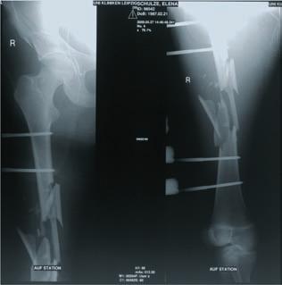
6 Sirus Antegrade Femoral Nail System Sample Cases Proximal Diaphyseal Fracture Preoperative Postoperative Postoperative after 7 weeks


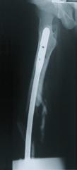
7 Sirus Antegrade Femoral Nail System Diaphyseal Fracture Preoperative Postoperative Postoperative after 3 months
8 Sirus Antegrade Femoral Nail System Surgical Technique Positioning of the Patient The patient is placed on the operating table in the supine position. The unaffected leg is flexed 90 at the hip and placed abducted in a leg holder. After the patient is in the correct position, the C-arm must be adjusted so that the femur can be imaged in a lateral and anterior-posterior view along its whole length In the same position an extension table can be used if needed. Patient in the supine position Note Alternatively a lateral positioning of the patient can be chosen. Patient in the supine position with extension shoe Patient in the supine position on an extension table with a Kirschner horseshoe
9 Sirus Antegrade Femoral Nail System Opening of the Medullary Canal 1. Incision of the Skin Extending the femoral shaft axis about 70 mm proximal to the tip of the trochanter, a longitudinal incision of about 40 mm is made. The fascia is split longitudinally in the direction of the tip of the trochanter, so that the greater trochanter can be palpated with the fingertip. Incision of the skin 2. Entry Point of the Nail The entry point of the intramedullary nail lies transversally in the extension of the axis of the medullary canal, directly lateral to the tip of the greater trochanter. Point of insertion of the intramedullary nail (red)
10 10 Sirus Antegrade Femoral Nail System 3. Insertion of the Guide Rod The guide rod 3.0 mm, length 365 mm (REF ), is clamped into a drill or into the universal chuck (REF ) and, with the help of the image intensifier, placed at the correct point of entry. It is then pushed forward with oscillating movements about 150 mm into the medullary canal. Next, the drill or universal chuck is removed and the correct position of the guide rod confirmed in both planes with the image intensifier. Insertion of the guide rod into the medullary canal 4. Opening of the Medullary Canal Slide the tissue protection sleeve ( 13 mm) (REF ) over the guide rod ( 3.0 mm, length 365 mm) (REF ). The cannulated awl ( 13 mm) (REF ) is pushed forward over the guide rod using light rotating motions until the stop on the tissue protection sleeve is seated. Opening of the medullary canal with the cannulated awl and the tissue protection sleeve over the guide rod
11 Sirus Antegrade Femoral Nail System Alternative Method for Opening of the Medullary Canal In case of dense or hard bone, the medullary canal can be opened with the drill bit with flexible shaft ( 13 mm) (REF ). The medullary canal is predrilled until the stop on the tissue protection sleeve is seated. Opening of the medullary canal using the drill bit with flexible shaft
12 12 Sirus Antegrade Femoral Nail System Nonreamed Method Insertion of the Guide Wire Insertion of the guide wire with the universal chuck over the tissue protection sleeve Remove all entry point opening instruments, exept the tissue protector. Insert the guide wire ( 3.0 mm, length 950 mm) (REF ) through the tissue protection sleeve into the medullary canal with the universal chuck (REF ). The correct position of the guide wire should be checked by using the image intensifier in both planes. For further procedures go to page 15. Note To simplify the insertion into the distal fragment in the case of a difficult reduction, the tip of the guide wire can be slightly bent. In addition the usual repositioning techniques can be used. Especially in difficult cases, the joystick technique might be a reasonable option. In the distal metaphyseal area of the femur, attention should be paid to place the guide wire centrally in the medullary canal in both planes.
13 Sirus Antegrade Femoral Nail System 13 Reamed Method Note For the reamed method, the instrumentation for the intramedullary reaming is needed. Insertion of the reaming rod with offset ball tip over the tissue protection sleeve 1. Insertion of the Reaming Rod The tissue protection sleeve ( 13 mm) used in the opening of the medullary canal is left in position. The awl or drill bit with flexible shaft and the guide rod are removed. The reaming rod with offset ball tip ( 3.0 mm) is inserted using the universal chuck (REF ) and the image intensifier. The correct position of the tip of the reaming rod and the correct reposition of the fracture is then confirmed in both planes. In cases of difficult repositioning, the usual repositioning techniques can be used. In particular the joystick technique might be a good option. In the distal metaphyseal area of the femur, attention should be paid to place the reaming rod centrally in the medullary canal in both planes.
14 14 Sirus Antegrade Femoral Nail System 2. Reaming the Medullary Canal The medullary canal is reamed in 0.5 mm stages over the reaming rod with offset ball tip ( 3.0 mm). To prevent heat necroses, reaming must be carried out with sharp drill bits. Excessive pressure must be avoided. Reaming of the medullary canal It is recommended to ream 1 mm larger than the chosen nail diameter. 3. Replacement of the Reaming Rod with Ball Tip by the Smooth Guide Wire The reaming rod with ball tip is replaced with the smooth guide wire. To prevent dislocation of the bone fragments during this process, the medullary tube (REF ) is pushed over the reaming rod with offset ball tip (REF ). The reaming rod is then removed and replaced with the smooth guide wire ( 3.0 mm, length 950 mm) (REF ). Finally, the medullary tube is removed. Insertion of the medullary tube in order to replace the reaming rod with offset ball tip with the guide wire
15 Sirus Antegrade Femoral Nail System 15 Insertion of the Intramedullary Nail for Femur Note The Sirus intramedullary nail has an anatomical shape. Therefore there are different nails for left and right. Nails marked LEFT must be used for the left femur only. Nails marked RIGHT must be used for the right femur only. Connection screw for the targeting device REF Intramedullary nail for femur and targeting device 1. Attaching the targeting device The length and diameter of the intramedullary nail are determined intraoperatively using the measuring device (REF ) or preoperatively using the X ray templates (lateral view REF and AP view REF ). The targeting device (REF ) is attached to the intramedullary nail and fixed with the connection screw (REF ). When doing this, the cams of the targeting device have to be engaged in the grooves of the intramedullary nail and the connection screw firmly tightened. Targeting device for femur REF Sirus intramedullary nail for femur
16 16 Sirus Antegrade Femoral Nail System 2. Nail Insertion Due to the anatomical nail shape the nail must be rotated approximately 90 during insertion. By applying this technique, stress peaks in the bone can be avoided. Insertion of the intramedullary nail for femur over the guide wire with a 90 rotation after passage of the proximal metaphysis The intramedullary nail for femur and targeting device unit is inserted over the smooth guide wire ( 3.0 mm) into the medullary canal by hand using light pressure with the targeting device oriented anteriorly. Since the patient is in the supine position, the targeting device therefore points upwards. After passage of the proximal metaphysis the targeting device is slowly rotated by pushing the nail further down the intramedullary canal. At the end of the insertion the targeting device is rotated by approximately 90 and lies in a lateral direction.
17 Sirus Antegrade Femoral Nail System 17 Alternative Insertion Method If necessary, the intramedullary nail can be driven with light, controlled blows into the medullary canal. To do this, the ram guide (REF ) is screwed onto the connection screw (REF ) and the ram (REF ) then mounted onto the guide. Finally the driving head (REF ) is screwed onto the ram guide. Controlled driving-in of the intramedullary nail with the ram Note It is important that the nail advances into the medullary canal with each blow. If this is not the case, the impaction must be stopped and the cause determined using the image intensifier. If necessary, a nail with a smaller diameter must be used or the medullary canal reamed larger. After nail insertion, the ram guide assembly is removed from the connection screw. The connection screw remains firmly attached to the intramedullary nail and the targeting device. 3. Removal of the Smooth Guide Wire ( 3.0 mm, Length 950 mm) 4. Confirmation of the Final Position of the Intramedullary Nail for Femur The final position of the intramedullary nail must be checked in both planes with the image intensifier. In particular, the correct rotation of the extremity must be checked at this time. Removal of the guide wire immediately after insertion of the intramedullary nail for femur
18 18 Sirus Antegrade Femoral Nail System Options for Proximal Locking Note The reaming rod or guide wire must be removed before locking the nail. Targeting device with the tissue protection sleeve and trocar in position for static locking Standard Proximal Locking The standard proximal locking can be carried out statically or dynamically depending on the type of fracture. The hole on the targeting device marked with STAT is used for the static locking. The hole on the targeting device marked with DYNAM is used for the dynamic locking. Targeting device with the tissue protection sleeve and trocar in position for dynamic locking Note If the cervical screws are inserted proximally, dynamic locking cannot be used. However the combination of the cervical screws with the proximal static locking screw is possible.
. Insertion of the three cervical screws Note If inserting the cervical screws, at least the two screws in the nail must be used.")
19 Sirus Antegrade Femoral Nail System 19 Cervical Screw Locking In the case of subtrochanteric fractures (diaphyseal as well as ipsilateral fractures and femoral neck), the proximal region can be locked with up to three special recon screws (REF to.077). Insertion of the three cervical screws Note If inserting the cervical screws, at least the two screws in the nail must be used. It is recommended, especially with ipsilateral femoral neck fractures, to insert the third cervical screw which lies on the anterior nail side. An additional targeting module is screwed onto the targeting device and serves as a guide when inserting the cervical screws. Targeting module REF
20 20 Sirus Antegrade Femoral Nail System Surgical Steps for Standard Proximal Locking Note It is recommended to do the proximal locking first since the targeting device may irritate the soft tissue. In addition, the distal locking without the targeting device attached is easier to carry out because the leg can be positioned in abduction if needed. Removal of the guide wire If compression of a shaft fracture is required, distal locking should be achieved first and then slight extracting motions should be applied before removing the ram guide assembly. Note If using the dynamic locking, the cervical screws cannot be used. 1. Removal of the Guide Wire ( 3.0 mm, Length 950 mm) Before locking, the smooth guide wire must be removed and it needs to be checked if the connection screw is firmly attached to the nail. If not, the screw needs to be retightened. 2. Insertion of the Tissue Protection Sleeve with the Trocar The tissue protection sleeve ( 10.0/8.0 mm) (REF ) with inserted trocar 8.0 mm (REF ) is introduced into the appropriate guide hole, marked STAT or DYNAM. The skin is incised at the appropriate site and dissected bluntly to the bone with scissors and clamp. The tissue protection sleeve together with the trocar are inserted until it touches the bone surface. The trocar is then removed. Insertion of tissue protection sleeve and trocar
21 Sirus Antegrade Femoral Nail System Drilling of the Locking Holes The drill guide 8.0/4.0 mm (REF ) is inserted into the tissue protection sleeve. Using the three-fluted drill bit 4.0 mm (REF ), both cortices are drilled through. Note Before drilling, ensure the guide wire ( 3.0 mm, length 950 mm) has been removed. Setting of the first locking hole 4. Measuring of the Screw Length The screw length is determined with the measuring device for locking screws (REF ). Reading off the screw length from the edge Alternatively, the screw length can be read directly from the drill. It is important that the tissue protection sleeve touches the bone when the screw length is being read from the drill. Measuring of the screw length with the measuring device for locking screws Scale to determine screw length
22 22 Sirus Antegrade Femoral Nail System 5. Insertion of the Locking Screw ( 4.9 mm) The previously determined locking screw ( 4.9 mm) is inserted through the tissue protection sleeve (REF ). Insertion of the screw over the tissue protection sleeve 6. Confirmation of the Correct Locking Screw Placement The correct placement of the inserted locking screw should be confirmed in both planes under the image intensifier. 7. Insertion of the Dynamic Locking Screw For dynamic locking, the procedure is similar to surgical steps 1 to 6, whereby the intended hole (DYNAM) on the targeting device is to be used. It is recommended to use the solid screw driver (REF ) for the insertion of the 3.9 and 4.9 mm interlocking screws.
23 Sirus Antegrade Femoral Nail System 23 Surgical Steps for Cervical Screws Note If inserting the cervical screws, at least the two screws inserted in the nail must be used. It is recommended, especially with ipsilateral femoral neck fractures, to insert the third cervical screw which lies on the anterior nail side. Removing of the guide wire When using the cervical screws, the proximal dynamic locking hole cannot be used. 1. Removal of the Guide Wire ( 3.0 mm, Length 950 mm) Before locking, the smooth guide wire must be removed and it needs to be checked if the connection screw is firmly attached to the nail. If not, the screw needs to be retightened. 2. Reducing the Fracture Before locking with the cervical screws, attention should be paid that the femoral head has been properly reduced. Reduced ipsilateral femoral neck fracture If the anatomical reduction cannot be achieved with the closed technique especially concering malrotation of the femoral head and neck fragment the incision for the cervical screws should be enlarged, that a forceps can be used for reduction. Axial view of the repositioned fracture
. Note With the right femur RIGHT and with the left femur LEFT is visible.")
24 24 Sirus Antegrade Femoral Nail System 3. Fastening of the Targeting Module The targeting module for cervical screws (REF ) is fastened with the screw for targeting module (REF ) to the targeting device for femur (REF ). Note With the right femur RIGHT and with the left femur LEFT is visible. On the lateral side of the targeting module RIGHT must be visible for the right femur, whereas LEFT must be visible for the left femur. Example: Targeting module firmly attached on the targeting device with a right intramedullary nail for femur. Important: RIGHT must then be visible from the lateral side 4. Insertion of the Tissue Protection Sleeve with Trocar Caution The distal cervical screw should lie near Shenton s arch. Therefore in a first step, the exact position of the intramedullary nail with respect to its penetration depth should be determined in the anterior-posterior plane. The tissue protection sleeve with inserted trocar in the distal targeting hole of the targeting module The skin is incised at the appropriate site. The tissue protection sleeve ( 10.0/8.0 mm) (REF ) with inserted trocar ( 8.0 mm) (REF ) is introduced into the distal targeting hole of the targeting module and pushed forward up to the bone.
25 Sirus Antegrade Femoral Nail System Insertion of the First Guide Wire Replacing the trocar and tissue protection sleeve, the positioning guide for cervical screws (REF ) is placed into the targeting hole. The guide wire 2.0 mm, length 440 mm (REF ), is inserted through the positioning guide. The guide wire should be brought about 4 mm past the cortex at Shenton s arch and be inserted up to about 2 mm before the cortex of the femoral head. The correct position of the guide wire needs to be checked in the axial view using the image intensifier. The wire needs to be parallel to the femoral neck axis and end up in the center of the femoral head. Measuring the length of the inserted guide wire with the measuring device for cervical screws. Next, the length of the inserted guide wire is measured with the measuring device for cervical screws (REF ). Note The measuring device for cervical screws measures the actual length of the guide wire in the bone. If the tip of the guide wire was inserted into the subcortical bone, the appropriate cervical screw must be chosen approximately 10 mm shorter.
26 26 Sirus Antegrade Femoral Nail System 6. Insertion of the Second Guide Wire Caution The inserted distal guide wire and the positioning guide should be maintained while the other guide wires are introduced. The positioning guide serves to stabilize and correct the positioning of the guide wires with respect to each other. Measuring the length of the second inserted guide wire with the measuring device over the tissue protection sleeve and drill guide by doing so, the positioning guide remains in the distal hole For the proximal cervical screw, the skin is opened at the entry point. The tissue protection sleeve 10.0/8.0 mm (REF ) with inserted trocar 8.0 mm (REF ) is introduced into the proximal targeting hole of the targeting module (REF ) and pushed forward until reaching the bone. The trocar is replaced by the drill guide 8.0/2.0 mm (REF ). Next, the second guide wire 2.0 mm, length 440 mm (REF ), is inserted. The penetration depth of the guide wire is again read on the measuring device for cervical screws (REF ). The drill guide must be inserted completely into the tissue protection sleeve. 7. Insertion of the Third Guide Wire In the case of ipsilateral femoral neck fractures, the use of a third guide wire is recommended. The procedure is identical to step 6. In this case, the positioning guide also remains in its initial position with the distal guide wire. The correct position of the third guide wire needs to be confirmed with image intensifier in the axial view. Measuring the length of the third inserted guide wire with the measuring device by doing so, the positioning guide remains in the distal hole
27 Sirus Antegrade Femoral Nail System Drilling of the Proximal Cervical Screw Hole The tissue protection sleeve (REF ) is inserted in the proximal hole of the targeting module. Drilling with the step reamer 6.5/4.5 mm (REF ) is done cautiously over the proximal guide wire through the tissue protection sleeve. Always use the image intensifier during the reaming process to control the position of the reamer in the femoral head and to make sure that the guide wire does not advance. Drilling for the distal cervical screw with the step reamer Confirm the previously determined screw length with the scaling on the reamer. 9. Insertion of the Proximal Cervical Screw Using the cannulated screwdriver (REF ), onto which the extension (REF ) is placed, the cannulated cervical screw (REF to.077) is screwed in over the guide wire through the tissue protection sleeve. The cervical screw should be inserted carefully. In the case of weak cancellous bone, the danger of overrotation exists, even with very low insertion torques. Afterwards the guide wire is removed. Next, the correct position of the cervical screw is checked in both planes with the image intensifier. Drilling with the step reamer for the ventral cervical screw, with the two previously inserted cervical screws 10. Insertion of Further Cervical Screws The distal and if needed the anterior cervical screw is inserted in the same way as described previously. The positioning guide is replaced with the tissue protection sleeve if needed. Note Before drilling, the parallel position of the guide wires needs to be confirmed with the image intensifier in both planes, as the distal wire can be misguided by the Shenton s arch.
28 28 Sirus Antegrade Femoral Nail System Surgical Steps for Distal Locking Note To statically lock at least two distal screws should be inserted. Before locking, the guide wire must be removed 1. Removal of the Guide Wire 3.0 mm, Length 950 mm Before locking, the guide wire must be removed. 2. Positioning of the C-arm The C-arm needs to be positioned so that the intended locking hole appears circular in the monitor and is found approximately in the center of the image. Wrong Right 3. Incision of the Skin The skin is incised over the selected hole on the lateral side of the femur. After spreading the soft tissues, the site is prepared with scissors or a clamp bluntly up to the bone. Incision of the skin with the scalpel
29 Sirus Antegrade Femoral Nail System Drilling of the Locking Holes Using the C-arm and radiolucent drill attachment, the tip of the drill bit 4.0 mm (REF ) is centred above the appropriate locking hole. Both cortices are then drilled through. Centering of the drill bit in the middle of the nail hole In order to avoid injury to the dorsal nerves and blood vessels when using the locking holes in the sagittal plane, the second cortex must be drilled through with special care. The skin incision must be anterior. 5. Measuring of the Screw Length The screw length is determined with the measuring device for locking screws (REF ). Note The screw length is read off directly. 6. Insertion of the Locking Screw The previously selected self-tapping locking screw 4.9 mm is inserted. 7. Confirmation of the Correct Locking Screw Placement The correct placement of each inserted locking screw must be checked in both planes with the image intensifier. 8. Insertion of Further Distal Locking Screws For each further locking screw, steps 2 to 7 are repeated.
30 30 Sirus Antegrade Femoral Nail System Possibility of Dynamic Distal Locking 1. Insertion of the Locking Screw for Later Dynamic Locking If a secondary dynamic locking is required, a locking screw can be inserted at the distal end of the long hole. The procedure corresponds to the previously described steps. Insertion of the locking screw for later dynamic locking 2. Activation of the Dynamic Locking To activate the dynamic locking, the static locking screws have to be removed. Distal dynamic locking screw after the removal of the static locking screws
31 Sirus Antegrade Femoral Nail System 31 Cap Screw If a femoral nail is inserted too deep in the medullary canal, the different lengths of cap screws ensure that the extra distance can be compensated. The cap screws are available in lengths from 0 to 25 mm (in 5 mm steps). Insertion of the cap screw over the guide wire with the hexagonal screwdriver 1. Insertion of the Guide Wire The guide wire 2.0 mm, length 300 mm (REF ), is inserted into the intramedullary nail through the connection screw of the targeting device which is still attached. 2. Removal of the Connection Screw and the Targeting Device The connection screw and the targeting device are removed. The inserted guide wire remains in the intramedullary nail. 3. Insertion of the Cap Screw The previously selected cap screw is inserted over the guide wire using the cannulated screwdriver (REF ). 4. Confirmation that the Cap Screw is Properly Seated The correct seat of the cap screw in the intramedullary nail must be checked using the image intensifier. 5. Removal of the Guide Wire
32 32 Sirus Antegrade Femoral Nail System Implants Sirus Intramedullary Nail for Femur Sirus Intramedullary nail for femur right, sterile Titanium Titanium A mm L mm REF A mm L mm REF L A * US patent No. 6, 461, 360 B1
33 Sirus Antegrade Femoral Nail System 33 Sirus Intramedullary nail for femur left, sterile Titanium Titanium A L A mm L mm REF A mm L mm REF * US patent No. 6, 461, 360 B1


34 34 Sirus Antegrade Femoral Nail System Sirus Cap screw, for femur 3.5 mm Quantity* REF Titanium Sirus Cap screw, for femur L Graphic case for implants, femur (with content), includes graphic case, insert locking screws, cervical screws and end caps Graphic case (empty) Quantity* REF F REF mm Titanium L mm Quantity* REF Insert (empty) for cervical screws Quantity* REF /3 Screw forceps self-holding Quantity* REF * Indicates the quantity in the graphic case for implants, femur REF stands for 1 piece.

35 Sirus Antegrade Femoral Nail System 35 Locking screw, self-tapping Cervical screw cannulated 4.3 mm 4.9 mm 8.0 mm 6.5 mm L 3.5 mm 4.5 mm L 6.5 mm 3.5 mm Drill 4.0 mm Step reamer 4.5 / 6.5 mm cannulated Titanium L mm Quantity* REF Titanium L mm Quantity* REF

 REF 110.99.")
 Quantity* REF 1 100.99.")
36 36 Sirus Antegrade Femoral Nail System Instruments Sirus Intramedullary Nail for Femur Combination wrench hexagonal mm L mm Quantity* REF Ram Quantity* REF Universal chuck cannulated, with T-handle L mm Quantity* REF Three-fluted drill bit, with quick coupling Graphic case for instruments, femur (with content) REF F Insert (empty) Quantity* REF /4 mm L mm Quantity* REF Graphic case (empty) Quantity* REF Hexagonal screwdriver large, cannulated mm L mm mm Quantity* REF * Indicates the quantity in the graphic case for implants, femur REF stands for 1 piece.


37 Sirus Antegrade Femoral Nail System 37 Hexagonal screwdriver, solid mm L mm mm Quantity* REF Measuring device, for locking screws Quantity* REF Drill guide mm Quantity* REF 8.0/ Elongation, for hexagonal screwdriver mm L mm mm Quantity* REF Guide wire, for cap screws mm L mm Quantity* REF Guide rod, with threaded tip mm L mm Quantity* REF Cleaning wire mm L mm Quantity* REF Guide wire mm L mm Quantity* REF Ratchet wrench mm Quantity* REF Ram guide Quantity* REF Connection screw, for targeting device Quantity* REF Chuck mm Quantity* REF Tissue protection sleeve Driving head mm Quantity* REF 10.0/ Quantity* REF Awl cannulated Trocar mm Quantity* REF mm Quantity* REF


38 38 Sirus Antegrade Femoral Nail System Targeting device, for femur Quantity* REF Positioning guide, for cervical screws Quantity* REF Measuring device Quantity* REF Targeting module, for cervical screws Quantity* REF Screw, for targeting module Quantity* REF Measuring device, for cervical screws Quantity* REF Drill guide mm Quantity* REF 8.0/ Guide wire, with threaded tip, for cervical screws mm L mm Quantity* REF Drill bit, with flexible shaft mm L mm Quantity* REF Three-fluted drill bit, with quick coupling mm L mm Quantity* REF SRTD handle L mm Quantity* REF SRTD tissue protection sleeve mm Quantity* REF 12.0/ Step reamer cannulated, for cervical screws mm Quantity* REF 6.5/ * Indicates the quantity in the graphic case for implants, femur REF stands for 1 piece. Tissue protection sleeve mm Quantity* REF 15/ SRTD drill guide mm Quantity* REF
39 Sirus Antegrade Femoral Nail System 39 SRTD prick punch mm Quantity* REF X ray template femur, lateral view Quantity* REF X ray template femur, AP view Quantity* REF
40 Copyright 2006 by Zimmer GmbH Printed in Switzerland Subject to change without notice Contact your Zimmer representative or visit us at Lit.No x Ed. 10/2006 ZHUB +H /$061001J060
Orthopedic Bone Nail System - Distal Femoral Nail Surgical Technique Manual
 Orthopedic Bone Nail System - Distal Femoral Nail Surgical Technique Manual Note: The surgical procedures should be performed under the guidance of qualified skilled orthopedic surgeons, and this surgical
PediNail Pediatric Femoral Nail
 PediNail Pediatric Femoral Nail Surgical Technique Table of Contents Indications...3 Patient Positioning...3 Approach...4 Reaming...5 Nail Placement...6 Proximal Interlocking...7 Distal Interlocking...8
NCB Proximal Humerus Plating System
 NCB Proximal Humerus Plating System Surgical Technique The right locking option for tough fractures Disclaimer This document is intended exclusively for experts in the field, i.e. physicians in particular,
NCB Distal Femur System. Surgical Technique
 NCB Distal Femur System Surgical Technique NCB Distal Femur System Surgical Technique 3 Surgical Technique NCB Distal Femur System Table of Contents Introduction 4 Indications 8 Preoperative Planning
PediLoc 3.5mm and 4.5mm Contour Femur Plate Surgical Technique
 PediLoc 3.5mm and 4.5mm Contour Femur Plate Surgical Technique Surgical Technique Contour Femur Plate The technique description herein is made available to the healthcare professional to illustrate the
NeoGen Femoral Nail System
 NeoGen Femoral Nail System LESS IS MORE TE-2070-04 Surgical Technique BLE OF CONTENT Preface Standard Femoral Mode Recon Mode Post-Operative Management Appendix Products Information Indication Patient
3. Insert Tocar Sleeves Insert the NCB tissue protection sleeve assembly 1.6 to 10mm through a skin incision (Fig. 38).
.") NCB Proximal Humerus Plating System Surgical Technique 19 2. Temporary Plate Fixation The plate can be temporary fixed to the bone with 1.6mm K-wire through the proximal cannulated fixation screw of the
NCB Proximal Humerus Plating System Surgical Technique 19 2. Temporary Plate Fixation The plate can be temporary fixed to the bone with 1.6mm K-wire through the proximal cannulated fixation screw of the
PediLoc 3.5mm and 4.5mm Bowed Femur Plate Surgical Technique
 PediLoc 3.5mm and 4.5mm Bowed Femur Plate Surgical Technique 2957 Bow Broch_REV_B.indd 1 2/10/11 12:47 PM Surgical Technique Bowed Femur Plate The technique description herein is made available to the
Zimmer Natural Nail System
 Zimmer Natural Nail System Antegrade Femoral Nail Surgical Technique (Piriformis Fossa & Greater Trochanteric Approaches) Zimmer Natural Nail System Antegrade Femoral Surgical Technique 1 Zimmer Natural
Zimmer ITST Intertrochanteric/ Subtrochanteric Fixation System. Abbreviated Surgical Technique
 Zimmer ITST Intertrochanteric/ Subtrochanteric Fixation System Abbreviated Surgical Technique ITST System Abbreviated Surgical Technique Indications The ITST Intramedullary Nail is indicated for use in
Femoral Recon Nail System FRN
 Greater Trochanter Piriformis Fossa Approaches For Intramedullary Fixation of Femoral Shaft Fractures Femoral Recon Nail System FRN Surgical Technique Table of Contents AO Principles 2 Indications and
TITANIUM TIBIAL NAIL SySTEM
 TITANIUM TIBIAL NAIL SySTEM Solid and Cannulated Nails SURGICAL TEChNIqUE Table of contents Introduction Indications 2 Preoperative Implant Selection 6 Surgical Technique Instruments for Opening the Tibia
The Titanium Tibial Nail System
 The Titanium Tibial Nail System Solid Tibial Nails (UTN) and Cannulated Tibial Nails (CTN) Surgical Technique This publication is not intended for distribution in the USA. Instruments and implants approved
Femoral Recon Nail System FRN
 Greater Trochanter Piriformis Fossa Approaches For Intramedullary Fixation of Femoral Shaft Fractures Femoral Recon Nail System FRN Surgical Technique Image intensifier control This description alone does
Pre-Operative Planning. Positioning of the Patient
 Surgical Technique Pre-Operative Planning Decide upon the size and angle of the barrel plate to be used from measuring the x-rays. To maximise the sliding action when using shorter lag screws, the Short
Technique Guide. SureLock Distal Targeting Device. C-arm guided targeting for trochanteric fixation nail.
 Technique Guide SureLock Distal Targeting Device. C-arm guided targeting for trochanteric fixation nail. Table of Contents Introduction SureLock Distal Targeting Device 2 Surgical Technique Preoperative
3. PATIENT POSITIONING & FRACTURE REDUCTION 3 8. DISTAL GUIDED LOCKING FOR PROXIMAL NAIL PROXIMAL LOCKING FOR LONG NAIL 13
 Contents IMPLANT FEATURES 2 1. INDICATIONS 3 2. PRE-OPERATIVE PLANNING 3 3. PATIENT POSITIONING & FRACTURE REDUCTION 3 4. INCISION 4 5. ENTRY POINT 4-6 6. PROXIMAL NAIL INSERTION 6-7 7. PROXIMAL LOCKING
Titanium Distal Femoral Nail System
 For Retrograde Insertion Titanium Distal Femoral Nail System Surgical Technique Table of Contents Introduction Titanium Distal Femoral Nail System 2 AO Principles 4 Indications 5 Clinical Cases 6 Surgical
Double Engine Orthopedic Bone Nail System Universal Humeral Nail
 Double Engine Orthopedic Bone Nail System ----------- Universal Humeral Nail Surgical Technique Manual Note: The surgical procedures should be performed under the guidance of qualified skilled orthopedic
System. Humeral Nail. Surgical Technique
 System Humeral Nail Surgical Technique Contents IMPLANT FEATURES 2 1. INDICATIONS 3 2. PRE-OPERATIVE PLANNING 3 3. PATIENT POSITIONING & FRACTURE REDUCTION 3 4. INCISION 4 5. ENTRY POINT 4-6 6. PROXIMAL
humerus InSafeLOCK Nail
 humerus InSafeLOCK Nail Introduction Content Humerus InSafeLOCK Nail is an innovative intramedullary nailing system, developed for humerus problems. Humerus fractures have 5-6 % incidence of all bone fractures.
Expert A2FN. Designed for small statured patients.
 Expert A2FN. Designed for small statured patients. Technique Guide Expert Nailing System This publication is not intended for distribution in the USA. Instruments and implants approved by the AO Foundation
OPERATING MANUAL AND TECHNIQUE GUIDE FOR TITANIUM FEMORAL AND TIBIAL NAILING SYSTEMS
 OPERATING MANUAL AND TECHNIQUE GUIDE FOR TITANIUM FEMORAL AND TIBIAL NAILING SYSTEMS ORTHO-MEDICAL GMBH TITANIUM FEMORAL NAIL OPERATIVE TECHNIQUE Introduction: Why a new type of femoral nail? The latest
Titanium Cannulated Lateral Entry Femoral Recon Nail
 Expert Nailing System Titanium Cannulated Lateral Entry Femoral Recon Nail Surgical Technique Table of Contents Introduction Titanium Cannulated Lateral Entry 2 Femoral Recon Nail Expert System AO Principles
NeoGen Tibia Nail System
 NeoGen Tibia Nail System LESS IS MORE TE-2070-03 Surgical Technique BLE OF CONTENT Preface Surgical Technique Appendix Products Information Patient Preparation Entry Portal Fracture Reduction Canal Preparation
Titanium Cannulated Adolescent Lateral Entry Femoral Nail. Expert Nailing System.
 Titanium Cannulated Adolescent Lateral Entry Femoral Nail. Expert Nailing System. Technique Guide EXPERT Nailing System Table of Contents Introduction Titanium Cannulated Adolescent Lateral Entry 2 Femoral
AcUMEDr. FoREARM ROD SYSTEM
 AcUMEDr FoREARM ROD SYSTEM FoREARM ROD SYSTEM Since 1988 Acumed has been designing solutions to the demanding situations facing orthopedic surgeons, hospitals and their patients. Our strategy has been
Surgical Technique. Forearm Fracture Solutions
 Surgical Technique Forearm Fracture Solutions Acumed is a global leader of innovative orthopaedic and medical solutions. We are dedicated to developing products, service methods, and approaches that improve
titanium cannulated adolescent lateral entry femoral nail
 titanium cannulated adolescent lateral entry femoral nail Expert Nailing System with Radiolucent Instrumentation SurgIcal technique Table of Contents Introduction Titanium Cannulated Adolescent Lateral
Expert A2FN. Designed for small statured patients.
 Expert A2FN. Designed for small statured patients. Surgical Technique Expert Nailing System This publication is not intended for distribution in the USA. Instruments and implants approved by the AO Foundation.
Antegrade Femoral Nail (AFN)
") Antegrade Femoral Nail (AFN) Surgical Technique This publication is not intended for distribution in the USA. Instruments and implants approved by the AO Foundation. Image intensifier control Warning This
Antegrade Femoral Nail (AFN) Surgical Technique This publication is not intended for distribution in the USA. Instruments and implants approved by the AO Foundation. Image intensifier control Warning This
TRAUMATOLOGY. Trochanter
 TRAUMATOLOGY Trochanter 1 References Prof. Dr. András Sárváry Head of Department Fővárosi Önkormányzat Péterfy Sándor úti Kórház Rendelőintézet és Baleseti Központ Budapest The following surgical description
Zimmer MIS Periarticular 3.5mm Proximal Tibial Locking Plate
 Zimmer MIS Periarticular 3.5mm Proximal Tibial Locking Plate Surgical Technique The Science of the Landscape Zimmer MIS Periarticular 3.5mm Proximal Tibial Locking Plate Surgical Technique 1 Zimmer MIS
Titanium Cannulated Retrograde/ Antegrade Femoral Nail
 Expert Nailing System With Radiolucent Instrumentation Titanium Cannulated Retrograde/ Antegrade Femoral Nail Surgical Technique Table of Contents Introduction Titanium Cannulated Retrograde/Antegrade
PediLoc Tibia Surgical Technique
 PediLoc Tibia PediLoc Tibia Surgical Technique The technique description herein is made available to the healthcare professional to illustrate the author s suggested treatment for an uncomplicated procedure.
GREENS SURGICALS. Redefining Excellence INSTRUMENT SYSTEM PREPARED BY: DR. VINAY KUMAR
 GREENS SURGICALS Redefining Excellence TIBIA AND FEMUR INSTRUMENT SYSTEM PREPARED BY: DR. VINAY KUMAR OPERATIVE TECHNIQUES INDEX SR.NO CONTENTS 1 LIST OF INSTRUMENT FOR TIBIA AND FEMUR. 2 RADIO GRAPH OF
Surgical Technique.
 Surgical Technique www.biomet.co.uk INTRODUCTION design principals Recent advances in imaging technology have enabled orthopaedic surgeons to extend closed treatment of femoral fractures to include more
Technique Guide. LCP Proximal Femoral Hook Plate 4.5/5.0. Part of the LCP Periarticular Plating System.
 Technique Guide LCP Proximal Femoral Hook Plate 4.5/5.0. Part of the LCP Periarticular Plating System. Table of Contents Introduction Features and Benefits 2 AO ASIF Principles 4 Indications 5 Surgical
KL 3255 PediNail_tech_Rev.D_Layout 1 10/8/12 1:18 PM Page 1. PediNail Pediatric Femoral Nail
 KL 3255 PediNail_tech_Rev.D_Layout 1 10/8/12 1:18 PM Page 1 Pediatric Femoral Nail KL 3255 PediNail_tech_Rev.D_Layout 1 10/8/12 1:18 PM Page 2 Surgical Technique Table of Contents Indications...2 Pre-operative
Expert ALFN. Adolescent Lateral Femoral Nail
 Expert ALFN. Adolescent Lateral Femoral Nail Surgical Technique EXPERT Nailing System This publication is not intended for distribution in the USA. Instruments and implants approved by the AO Foundation
PROXIMAL FEMORAL NAIL REMOVAL SET
 PROXIMAL FEMORAL NAIL REMOVAL SET for PFN, TFN and PFNA/PFNA-II Instruments and Implants approved by the AO Foundation. This publication is not intended for distribution in the USA. SURGICAL TECHNIQUE
Astrid Modular Forefoot System. Surgical Technique
 Astrid Modular Forefoot System Surgical Technique Table of Contents Astrid a System for Surgery of the Forefoot... Scarf Osteotomies...6 Stabilization by Means of Two Parallel Double-Threaded Screws Introduced
PediNail Pediatric Femoral Nail SURGICAL TECHNIQUE
 Pediatric Femoral Nail SURGICAL TECHNIQUE 2 2 TABLE OF CONTENTS System Overview Indications... 6 Proximal Locking Options... 6 Distal Locking Options... 6 Preoperative Planning... 7 Nail Size Selection...
Aesculap Targon TX. Intramedullary Nail for Tibial Fractures...going to X-tremes. Aesculap Orthopaedics
 Aesculap Targon TX Intramedullary Nail for Tibial Fractures...going to X-tremes Aesculap Orthopaedics Surgical Technique Preoperative Planning KH483 X-ray template Targon TX (KH483200 : 375 mm-420 mm KH48320
PFN. Proximal Femoral Nail Standard/Short, PFN Long PFN
 PFN. Proximal Femoral Nail Standard/Short, PFN Long PFN Surgical Technique This publication is not intended for distribution in the USA. Instruments and implants approved by the AO Foundation. 357.001
A New Benchmark in Tibial Fixation
 PediLoc T I B I A S U R G I C A L T E C H N I Q U E A New Benchmark in Tibial Fixation Multiple plate designs for more options in osteotomies and fracture fixation Engineered from exclusive data resulting
Biomet Large Cannulated Screw System
 Biomet Large Cannulated Screw System s u r g i c a l t e c h n i q u e A Complete System for Simplified Fracture Fixation 6.5mm & 7.3mm The Titanium, Self-drilling, Self-tapping Large Cannulated Screw
LCP Medial Distal Tibia Plate, without Tab. The Low Profile Anatomic Fixation System with Angular Stability and Optimal Screw Orientation.
 LCP Medial Distal Tibia Plate, without Tab. The Low Profile Anatomic Fixation System with Angular Stability and Optimal Screw Orientation. Technique Guide LCP Small Fragment System Table of Contents Introduction
PFNA-II. Proximal Femoral Nail Antirotation.
 PFNA-II. Proximal Femoral Nail Antirotation. Technique Guide This publication is not intended for distribution in the USA. Instruments and implants approved by the AO Foundation. Image intensifier control
Surgical Technique. Cannulated Angled Blade Plate 3.5 and 4.5, 90
 Surgical Technique Cannulated Angled Blade Plate 3.5 and 4.5, 90 Cannulated Angled Blade Plate 3.5 and 4.5, 90 Table of contents Indications/Contraindications 2 Implants 3 Surgical technique 5 Implant
Expert R /AFN Retrograde /Antegrade Femoral Nail.
 Expert R /AFN Retrograde /Antegrade Femoral Nail. Technique Guide Expert Nailing System Table of Contents Introduction Features 2 AO/ASIF principles of internal fixation 7 Indications 9 Cases 10 Retrograde
Surgical technique. UHN/PHN Humeral Nailing System.
 Surgical technique UHN/PHN Humeral Nailing System. 358.590 Radiographic Ruler for UHN 292.260 Kirschner Wire 2.5 mm with trocar tip, length 280 mm, Stainless Steel 351.120 Awl with T-Handle, cannulated,
Technique Guide. 3.5 mm LCP Low Bend Medial Distal Tibia Plate Aiming Instruments. Part of the 3.5 mm LCP Percutaneous Instrument System.
 Technique Guide 3.5 mm LCP Low Bend Medial Distal Tibia Plate Aiming Instruments. Part of the 3.5 mm LCP Percutaneous Instrument System. Table of Contents Introduction 3.5 mm LCP Low Bend Medial Distal
Monolateral External Fixation System for Trauma and Orthopaedics
 MEFiSTO Monolateral External Fixation System for Trauma and Orthopaedics Surgical Technique Original Instruments and Implants of the Association for the Study of Internal Fixation AO/ASIF MEFiSTO Table
LCP Medial Proximal Tibial Plate 3.5. Part of the Synthes small fragment Locking Compression Plate (LCP) system.
 system.") LCP Medial Proximal Tibial Plate 3.5. Part of the Synthes small fragment Locking Compression Plate (LCP) system. Technique Guide This publication is not intended for distribution in the USA. Instruments
LCP Medial Proximal Tibial Plate 3.5. Part of the Synthes small fragment Locking Compression Plate (LCP) system. Technique Guide This publication is not intended for distribution in the USA. Instruments
A Locking IM Rod that won't back out. Simple and straight to the point! SURGICAL TECHNIQUE
 A Locking IM Rod that won't back out. Simple and straight to the point! SURGICAL TECHNIQUE The SLIM (Simple Locking IntraMedullary) System is a new generation of pediatric orthopedic nails specifically
LCP Medial Proximal Tibial Plate 4.5/5.0. Part of the Synthes LCP periarticular plating system.
 LCP Medial Proximal Tibial Plate 4.5/5.0. Part of the Synthes LCP periarticular plating system. Technique Guide This publication is not intended for distribution in the USA. Instruments and implants approved
A locking plate system that expands a surgeon s options in trauma surgery. Zimmer NCB Plating System
 A locking plate system that expands a surgeon s options in trauma surgery Zimmer NCB Plating System The Power of Choice The power of having true intraoperative options is at your fingertips. Using standard
INTRAMEDULLARY. Medical Devices. Femur Intramedullary Nail
 FEMUR INTRAMEDULLARY Femur Intramedullary Nail Multi-functional Standard and Recon Antegrade and Retrograde Application Different Multi-Planner Locking Choices Medical Devices Introductions The new, multifunctional
US Patent No. 6,309,396B1. G. David Ritland, M.D.
 US Patent No. 6,309,396B1 G. David Ritland, M.D. The Femur Finder is designed to direct the guide wire into the medullary canal. Do not use it to manipulate the fracture fragments, reduce the fracture,
For intramedullary fixation of proximal femoral fractures SURGICAL TECHNIQUE
 For intramedullary fixation of proximal femoral fractures SURGICAL TECHNIQUE TABLE OF CONTENTS INTRODUCTION Clinical Cases 2 AO Principles 4 Indications and Precautions 5 SURGICAL TECHNIQUE Preparation
3.5 mm LCP Extra-articular Distal Humerus Plate
 Part of the DePuy Synthes Locking Compression Plate (LCP ) System 3.5 mm LCP Extra-articular Distal Humerus Plate Surgical Technique Table of Contents Introduction 3.5 mm LCP Extra-articular Distal Humerus
Technique Guide. DHS Blade. For osteoporotic bone.
 Technique Guide DHS Blade. For osteoporotic bone. Table of Contents Introduction Features and Benefits 2 Indications and Contraindications 4 Clinical Cases 5 Surgical Technique Implantation 6 Implant
Surgical Technique. CONQUEST FN Femoral Neck Fracture System
 Surgical Technique CONQUEST FN Femoral Neck Fracture System Table of Contents Introduction... 3 Indications... 3 Product Overview... 4 Surgical Technique... 5 Patient Positioning... 5 Reduce the Fracture...
Mandible External Fixator II. Provides treatment for fractures of the maxillofacial area.
 Mandible External Fixator II. Provides treatment for fractures of the maxillofacial area. Technique Guide This publication is not intended for distribution in the USA. Instruments and implants approved
Surgical Technique. Intramedullary locked Nailing With Screws for Humerus Fractures Solid/Cannulated. Humeral Interlocking Nail.
 Screws for Humerus Fractures Surgical Technique Humeral Interlocking Nail Approved by Humerus Nail Kit Code 08050001 Contents Introduction Implant design Indications Pre-operative planning Patient positioning
Expert ALFN. Adolescent Lateral Femoral Nail.
 Expert ALFN. Adolescent Lateral Femoral Nail. Surgical Technique EXPERT Nailing System This publication is not intended for distribution in the USA. Instruments and implants approved by the AO Foundation.
S U R G I C A L T E C H N I Q U E David A. McQueen, MD Return to Menu
 S U R G I C A L T E C H N I Q U E David A. McQueen, MD TOTAL KNEE INSTRUMENTS Wichita Fusion Nail Introduction...1 Preoperative Planning...2 Surgical Technique...3-8 Wichita Fusion Nail Surgical Technique
The Titanium Cannulated Tibial Nail with Proximal Bend. Expert nailing system.
 The Titanium Cannulated Tibial Nail with Proximal Bend. Expert nailing system. Technique Guide Expert Nailing System Table of Contents Introduction Titanium Cannulated Tibial Nail with 2 Proximal Bend
M/DN Femoral Interlocking & Recon Nail Intramedullary Fixation Surgical Technique
 M/DN Femoral Interlocking & Recon Nail Intramedullary Fixation Surgical Technique M/DN Femoral Interlocking & Recon Nail Intramedullary Fixation 1 Surgical Techniques for Fixation of Femoral Fractures
QUICK REFERENCE GUIDE. The Orthofix Femoral Nailing System. By Prof. Dr. D. Pennig
 QUICK REFERENCE GUIDE The Orthofix Femoral Nailing System By Prof. Dr. D. Pennig Whenever possible, femoral fractures should be stabilized within the first 24 hours following injury, provided the patient
3.5 MM VA-LCP PROXIMAL TIBIA PLATE SYSTEM
 3.5 MM VA-LCP PROXIMAL TIBIA PLATE SYSTEM Part of the DePuy Synthes Variable Angle Periarticular Plating System SURGICAL TECHNIQUE TABLE OF CONTENTS INTRODUCTION 3.5 mm VA-LCP Proximal Tibial Plate 2 AO
Expert R/AFN. Retrograde/Antegrade Femoral Nail.
 Expert R/AFN. Retrograde/Antegrade Femoral Nail. Surgical Technique EXPERT Nailing System This publication is not intended for distribution in the USA. Instruments and implants approved by the AO Foundation
PediLoc Extension Osteotomy Plate (PLEO)
") PediLoc Extension Osteotomy Plate (PLEO) Left PLEO Plates Sizes: 6, 8 and 10 hole plates Right PLEO Plates Sizes: 6, 8 and 10 hole plates PediLoc Extension Osteotomy Plate The technique description herein
PediLoc Extension Osteotomy Plate (PLEO) Left PLEO Plates Sizes: 6, 8 and 10 hole plates Right PLEO Plates Sizes: 6, 8 and 10 hole plates PediLoc Extension Osteotomy Plate The technique description herein
Surgical Technique. Fibula Rod System
 Surgical Technique Fibula Rod System Acumed is a global leader of innovative orthopaedic and medical solutions. We are dedicated to developing products, service methods, and approaches that improve patient
UHN/PHN Humeral Nailing System.
 UHN/PHN Humeral Nailing System. Surgical Technique This publication is not intended for distribution in the USA. Instruments and implants approved by the AO Foundation. 358.590 Radiographic Ruler for
Cannulated Pediatric Osteotomy System (CAPOS). A single system of osteotomy blade plates and cannulated instrumentation.
. A single system of osteotomy blade plates and cannulated instrumentation.") Cannulated Pediatric Osteotomy System (CAPOS). A single system of osteotomy blade plates and cannulated instrumentation. Technique Guide This publication is not intended for distribution in the USA. Instruments
Cannulated Pediatric Osteotomy System (CAPOS). A single system of osteotomy blade plates and cannulated instrumentation. Technique Guide This publication is not intended for distribution in the USA. Instruments
UFN Unreamed Femoral Nail CFN Cannulated Femoral Nail
 UFN Unreamed Femoral Nail CFN Cannulated Femoral Nail Surgical Technique This publication is not intended for distribution in the USA. Instruments and implants approved by the AO Foundation. UFN/CFN Unreamed/Cannulated
Antegrade Femoral Nail (AFN)
") Antegrade Femoral Nail (AFN) Surgical Technique This publication is not intended for distribution in the USA. Instruments and implants approved by the AO Foundation. Contents Indications/contraindications
Antegrade Femoral Nail (AFN) Surgical Technique This publication is not intended for distribution in the USA. Instruments and implants approved by the AO Foundation. Contents Indications/contraindications
operative technique Kent Hip
 operative technique Kent Hip The Kent Hip Operative Technique The Kent Hip was developed by Mr Cliff Stossel, FRCS in Maidstone, Kent, UK and first implanted in 1986. It was designed to deal with problems
LCP Distal Humerus Plates
 The anatomic fixation system for the distal humerus with angular stability Surgical technique LCP Locking Compression Plate Contents Indications and contraindications 2 Implants 3 Instruments 5 Preparation
Periarticular Aiming Arm Instruments for LCP Proximal Tibial Plate 4.5/5.0. Part of the LCP Periarticular Aiming Arm Instrument System (large).
.") Technique Guide Periarticular Aiming Arm Instruments for LCP Proximal Tibial Plate 4.5/5.0. Part of the LCP Periarticular Aiming Arm Instrument System (large). Image intensifier control Warning This description
Technique Guide Periarticular Aiming Arm Instruments for LCP Proximal Tibial Plate 4.5/5.0. Part of the LCP Periarticular Aiming Arm Instrument System (large). Image intensifier control Warning This description
3.5 mm Locking Attachment Plate
 For Treatment of Periprosthetic Fractures 3.5 mm Locking Attachment Plate Surgical Technique Table of Contents Introduction 3.5 mm Locking Attachment Plate 2 Indications 4 Surgical Technique Preparation
Zimmer MIS Periarticular Distal Femoral Locking Plate
 For Clinical Evaluations Zimmer MIS Periarticular Distal Femoral Locking Plate Surgical Technique The Science of the Landscape Zimmer MIS Periarticular Distal Femoral Locking Plate Surgical Technique
A locking plate system that expands a surgeon s options in trauma surgery. Zimmer NCB Plating System
 A locking plate system that expands a surgeon s options in trauma surgery Zimmer NCB Plating System The Power of Choice The power of having true intraoperative options is at your fingertips. Using standard
Gamma3 TM Fragment Control Clip
 Osteosynthesis Gamma3 TM Fragment Control Clip Operative Technique Hip Fracture Introduction Indication The Fragment Control Clip is designed to stabilize rotationally unstable femoral head-neck fragments
Principles of intramedullary nailing. Management for ORP
 Principles of intramedullary nailing Eakachit Sikarinklul,MD Basic Principles of Fracture Management for ORP Bangkok Medical Center Bangkok, 22-24 July 2016 Learning outcomes At the end of this lecture
Suprapatellar Instrumentation for Titanium Cannulated Tibial Nail. Expert nailing system.
 Suprapatellar Instrumentation for Titanium Cannulated Tibial Nail. Expert nailing system. Technique Guide Expert Nailing System Table of Contents Introduction Suprapatellar Instrumentation for Titanium
QUICK REFERENCE GUIDE. The PreFix Fixator (92000 Series) ALWAYS INNOVATING
 ALWAYS INNOVATING") 21 The PreFix Fixator (92000 Series) ALWAYS INNOVATING INTRODUCTION The PreFix fixator is designed to provide temporary external fixation. This may be needed when local facilities or the condition of the
21 The PreFix Fixator (92000 Series) ALWAYS INNOVATING INTRODUCTION The PreFix fixator is designed to provide temporary external fixation. This may be needed when local facilities or the condition of the
For Distal Femur Fractures. 95º Condylar Plate. Quick Reference Chart
 For Distal Femur Fractures 95º Condylar Plate Quick Reference Chart 95 Condylar Plate. Quick reference chart for distal femur fractures. Insert guide wires Fix condylar fragments with 6.5 mm cancellous
Titanium Solid Humeral Nail System
 For Antegrade or Retrograde Insertion With Spiral Blade, Conventional and Compression Locking Titanium Solid Humeral Nail System Surgical Technique Table of Contents INTRODUCTION Foreword.... 2 Indications....
LCP Anterolateral Distal Tibia Plate 3.5. The low profile anatomic fixation system with optimal plate placement and angular stability.
 LCP Anterolateral Distal Tibia Plate 3.5. The low profile anatomic fixation system with optimal plate placement and angular stability. Technique Guide LCP Small Fragment System Table of Contents Introduction
Zimmer Periarticular Proximal Humeral Locking Plate
 Zimmer Periarticular Proximal Humeral Locking Plate Surgical Technique The Science of the Landscape Zimmer Periarticular Proximal Humeral Locking Plate 1 Surgical Technique Table of Contents Introduction
M/DN Femoral Interlocking & Recon Nail Intramedullary Fixation Surgical Technique
 M/DN Femoral Interlocking & Recon Nail Intramedullary Fixation Surgical Technique M/DN Femoral Interlocking & Recon Nail Intramedullary Fixation 1 Surgical Techniques for Fixation of Femoral Fractures
Technique Guide. 3.5 mm LCP Low Bend Medial Distal Tibia Plates. Part of the Synthes locking compression plate (LCP) system.
 system.") Technique Guide 3.5 mm LCP Low Bend Medial Distal Tibia Plates. Part of the Synthes locking compression plate (LCP) system. Table of Contents Introduction 3.5 mm LCP Low Bend Medial Distal Tibia Plates
Technique Guide 3.5 mm LCP Low Bend Medial Distal Tibia Plates. Part of the Synthes locking compression plate (LCP) system. Table of Contents Introduction 3.5 mm LCP Low Bend Medial Distal Tibia Plates
Alignment Rod. For intraoperatively confirming correction of the mechanical leg axis.
 Alignment Rod. For intraoperatively confirming correction of the mechanical leg axis. Easy to use Accuracy of surgery Reduces X-ray exposure Table of Contents Introduction Alignment Rod 2 Handling Technique
Zimmer ITST Intertrochanteric/ Subtrochanteric Fixation System
 Zimmer ITST Intertrochanteric/ Subtrochanteric Fixation System Surgical Technique The functional fit ITST Intramedullary Nail Surgical Technique 1 Surgical Technique for the ITST Intramedullary Nail System
Humeral Nailing System
 UHN/PHN Humeral Nailing System Surgical Technique Image intensifier control This description alone does not provide sufficient background for direct use of DePuy Synthes products. Instruction by a surgeon