Expert R/AFN. Retrograde/Antegrade Femoral Nail.
|
|
|
- Violet Whitney Reynolds
- 6 years ago
- Views:
Transcription

1 Expert R/AFN. Retrograde/Antegrade Femoral Nail. Surgical Technique EXPERT Nailing System This publication is not intended for distribution in the USA. Instruments and implants approved by the AO Foundation
2
3 TABLE OF CONTENTS INTRODUCTION Expert R/AFN 4 AO Principles 7 Indications 9 Cases 10 Retrograde Approach 12 Opening the Distal Femur 12 Reaming (Optional) 21 Inserting Nail 22 Standard Locking 27 End Cap Insertion 32 Spiral Blade Locking (Optional) 33 End Cap Insertion 39 Freehand Locking 40 Interlocking with PAD for Expert RFN (Optional) 47 ANTEGRADE APPROACH Opening the Proximal Femur 52 Reaming (Optional) 61 Inserting Nail 62 Standard Locking 66 End Cap Insertion 67 Freehand Locking 69 Expert Retrograde/Antegrade Femoral Nail Surgical Technique DePuy Synthes 1
4 Table of Contents IMPLANT REMOVAL 70 PRODUCT INFORMATION Nails 75 Locking Implants 79 Instruments 83 Comparison Table 97 Handling Information 99 Modular Cases 101 Vario Case 105 Power Tools 107 Optional: Angular Stable Locking System (ASLS) DePuy Synthes Expert Retrograde/Antegrade Femoral Nail Surgical Technique
5 Image intensifier control Warning This description alone does not provide sufficient background for direct use of the instrument set. Instruction by a surgeon experienced in handling these instruments is highly recommended. Reprocessing, Care and Maintenance of Synthes Instruments For general guidelines, function control and dismantling of multi-part instruments, please refer to: Cleaning of instruments For detailed information please refer to Reprocessing, Care and Maintenance of Synthes Instruments, Article No For more information about alternative Expert Nail Instruments, please consult pages Expert Retrograde/Antegrade Femoral Nail Surgical Technique DePuy Synthes 3

6 EXPERT R/AFN RETROGRADE/ANTEGRADE FEMORAL NAIL ADVANCED NAIL DESIGN The nail design offers great flexibility One system for retrograde and antegrade technique One system for left and right femur Anatomic bend for ease in insertion and extraction Cannulation of all nails for guided insertion in reamed and unreamed technique Large portfolio with nail diameters ranging from B 9.0 to 15.0 mm and lengths ranging from 160 to 480 mm Versatile locking configuration for static, dynamic, standard and spiral blade locking retrograde RFN, mm straight retrograde RFN, mm antecurvature 1500 mm retrograde R/AFN, mm antecurvature 1500 mm antegrade R/AFN, mm antecurvature 1500 mm 4 DePuy Synthes Expert Retrograde/Antegrade Femoral Nail Surgical Technique

.")
7 UNIQUE DISTAL LOCKING OPTIONS The unique distal combination hole enables the optimal locking for every anatomical situation and fracture type. The surgeon can intraoperatively choose between spiral blade locking (with one spiral blade and one locking screw) and standard locking (with two locking screws). The end cap with self-retaining Stardrive recess allows for angular stable locking of the most distal locking implant in both configurations. Expert Retrograde/Antegrade Femoral Nail Surgical Technique DePuy Synthes 5
8 Expert R/AFN Retrograde/Antegrade Femoral Nail IMPROVED STABILITY End caps: Self-retaining Stardrive recess for effortless and secure end cap pick-up and insertion Possibility to block spiral blade or most distal (retrograde) or most proximal locking screw (antegrade) for absolute angular stability End cap prevents ingrowth of tissue and facilitates nail removal. locking screws with hexalobular internal drive according to EN ISO Stardrive T40 This patient has some Synthes Locking screws: Double thread for more contact points leading to enhanced stability Thread closer to screw head providing better bone purchase and improved stability Self-holding Stardrive recess for effortless and secure locking screw pick-up Titanium alloy TAN for improved mechanical and fatigue properties Adapted locking screw diameter to nail diameter: B 5.0 mm for nails B mm B 6.0 mm for nails B 14.0 and 15.0 mm locking screws with hexalobular internal drive according to EN ISO Stardrive T25 This patient has some Synthes Spiral blades: Optimal hold in osteoporotic bone by increased surface area Angular stable locking by end cap Titanium alloy TAN for improved mechanical and fatigue properties 6 DePuy Synthes Expert Retrograde/Antegrade Femoral Nail Surgical Technique

9 AO PRINCIPLES In 1958, the AO formulated four basic principles, which have become the guidelines for internal fixation 1, 2. 4_Priciples_03.pdf :08 Anatomic reduction Fracture reduction and fixation to restore anatomical relationships. 1 2 Stable fixation Fracture fixation providing absolute or relative stability, as required by the patient, the injury, and the personality of the fracture. Early, active mobilization Early and safe mobilization and rehabilitation of the injured part and the patient as a whole. 4 3 Preservation of blood supply Preservation of the blood supply to soft tissues and bone by gentle reduction techniques and careful handling. 1 Müller ME, M Allgöwer, R Schneider, H Willenegger. Manual of Internal Fixation. 3rd ed. Berlin Heidelberg New York: Springer Rüedi TP, RE Buckley, CG Moran. AO Principles of Fracture Management. 2nd ed. Stuttgart, New York: Thieme Expert Retrograde/Antegrade Femoral Nail Surgical Technique DePuy Synthes 7
10 AO Principles Preservation of blood supply When the canal is not reamed, intramedullary nailing generates minimal trauma to the endosteum and, therefore, the blood supply is maximised through the uninjured endosteum and periosteum. Reaming the canal temporarily disrupts the endosteal blood supply but probably stimulates the revascularisation and therefore the bone healing. Early, active mobilisation Intramedullary nailing, combined with the AO technique, provides relatively stable fracture fixation with minimal trauma to vascular supply. This helps to create an improved environment for bone healing, accelerating the patient s return to previous mobility and function. 8 DePuy Synthes Expert Retrograde/Antegrade Femoral Nail Surgical Technique
.")
11 INDICATIONS Indications for retrograde approach In retrograde approach, the Expert Retrograde/Antegrade Femoral Nail is indicated for fractures in the distal femur: 33-A1/A2/A3 33-C1/C2/C3.1 For the 33-C fractures, the Expert Retrograde/Antegrade Femoral Nail should be used in combination with other implants (not shown in the illustration). Additionally, the Expert Retrograde/Antegrade Femoral Nail is indicated for fractures in the femoral shaft: 32-A/B/C (except 32-A[1-3].1 and 32-B[1-3].1 (subtrochanteric fractures)) in case of: combination with fractured patella ipsilateral femur/tibia fractures (floating knee) combination with fractured acetabulum, pelvis, or femoral neck combinations of the fractures mentioned above pronounced adipositas pregnancy polytrauma (if numerous surgical teams are involved in treatment of patient) Note: In case of osteoporotic bone, it is strongly recommended to utilise spiral blade locking in the distal femur. Indications for antegrade approach In antegrade approach, the Expert Retrograde/ Antegrade Femoral Nail is indicated for fractures in the femoral shaft: 32-A/B/C (except 32-A[1-3].1 and 32-B[1-3].1 (subtrochanteric fractures) Note: ASLS, the Angular Stable Locking System, is indicated in cases where increased stability is needed, such as in fractures closer to the metaphyseal area or in poor quality bone. For more details regarding the intramedullary fixator principle, please consult the ASLS technique guide ( ) and concept flyer ( ). Expert Retrograde/Antegrade Femoral Nail Surgical Technique DePuy Synthes 9
12 CASES Case 1 Retrograde approach standard locking Case 1 Retrograde approach standard locking Case 3 Antegrade approach standard locking 11 DePuy Synthes Expert Retrograde/Antegrade Femoral Nail Surgical Technique
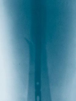
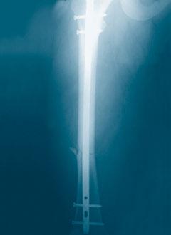
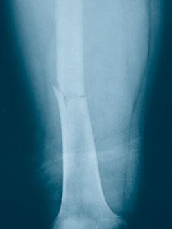
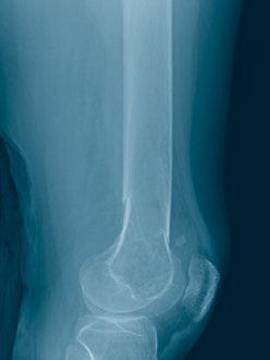

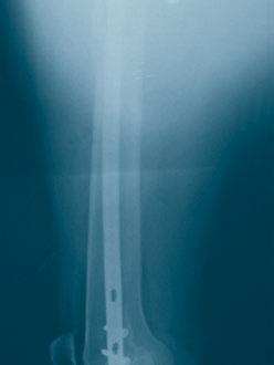
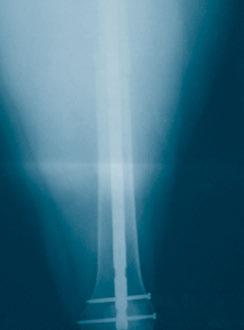
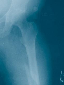
13 preoperative postoperative preoperative postoperative preoperative postoperative Expert Retrograde/Antegrade Femoral Nail Surgical Technique DePuy Synthes 11

14 RETROGRADE APPROACH OPENING THE DISTAL FEMUR 1 Position patient Position the patient supine on a radiolucent table. The knee of the injured leg should be flexed 70 to 90º allowing for correct reduction of the fracture and localisation of the nail entry point. A leg roll may be used to allow proper reduction and stabilisation of the fracture. Position the image intensifier in such a way that visualisation of the femur including the proximal and distal ends is possible in AP and lateral view. The contralateral leg should be flexed in the hip and in the knee and rested in an elevated position to enable visualisation by image intensifier. 2 Reduce fracture Perform closed reduction manually by axial traction under image intensifier. In case of older fractures, the use of the large distractor ( ) or pinless fixator ( ) may be appropriate under certain circumstances. Note: Intra-articular fractures should be stabilised with interfragmentary screw fixation prior to insertion of the nail. The screws should be positioned to not interfere with the path of the nail. 11 DePuy Synthes Expert Retrograde/Antegrade Femoral Nail Surgical Technique

15 3 Measure for length and diameter of nail Instruments Radiographic Ruler for Expert Femoral Nails, length 475 mm Radiographic Ruler for Nail Diameters for Expert Femoral Nails, length 365 mm The required nail length must be determined after reduction of the upper leg fracture. Position the image intensifier as for an AP view of the distal femur. Using long forceps, hold the ruler parallel to the femur on the lateral side of the upper leg. Position the ruler such that the distal end is at the desired nail insertion depth. Mark the skin at that site. Expert Retrograde/Antegrade Femoral Nail Surgical Technique DePuy Synthes 11

16 Retrograde Approach Opening the Distal Femur Move the image intensifier toward the proximal end of the femur, align the distal end of the ruler with the skin marking and record an AP x-ray of the proximal femur. Check the reduction and read off the required nail length on the ruler as it appears in the x-ray. Precautions: It is recommended that the tip of the nail is at least 5 cm above the most proximal extension of the fracture zone. Attention must be paid in the area 4 to 6 cm below the Lesser Trochanter because of the A. femoralis and the branches of the N. femoralis. In cases where such long nails (>320 mm) are used, it is recommended to place the AP locking as proximal as possible and above the Lesser Trochanter. The possibility of dynamisation must also be considered when determining the nail length and a correspondingly shorter nail should be chosen. The locking screw in the dynamic locking option can move by up to 5 mm distally. Alternatives Determine the nail length by the above procedure on the uninjured leg or before draping (non-sterile) or compare the length of two identical SynReam reaming rods B 2.5 mm ( ). 11 DePuy Synthes Expert Retrograde/Antegrade Femoral Nail Surgical Technique
.")
17 Place the radiographic ruler for nail diameters over the femur so that the measuring edge is located over the isthmus. Select the nail diameter shown when the medullary canal/cortex transition is still visible on both sides of the marking (12 mm in this example). If the reamed technique is used, the diameter of the largest medullary reamer applied must be 0.5 to 1.5 mm larger than the nail diameter. 4 Approach For 33-A.X and 32-X.X fractures either make a transligamental (ligamentum patellae) or a parapatellar incision. For 33-C.X fractures either make a medial or a lateral parapatellar approach depending on the type and location of fracture. Expert Retrograde/Antegrade Femoral Nail Surgical Technique DePuy Synthes 11

18 Retrograde Approach Opening the Distal Femur 5 Determine entry point The entry point for the Expert Retrograde/Antegrade Femoral Nail is in line with the medullary canal. The point is at the top of the intercondylar notch, just anterior and lateral to the femoral attachment of the posterior cruciate ligament. The entry point is determinant for the entire operation, especially for the optimal final position of the nail in the medullary canal respecting the anatomical conditions. This is mostly important for distal metaphyseal fractures regarding correct fragment placement. medial lateral 11 DePuy Synthes Expert Retrograde/Antegrade Femoral Nail Surgical Technique


19 6 Insert guide wire 7 9 Instruments Handle, with Quick Coupling and Protection Sleeve 13.0, for retrograde approach, with Quick Coupling and Multihole Drill Guide for Protection Sleeve 13.0, for retrograde approach or Protection Sleeve 13.0, for retrograde approach and Drill Sleeve 13.0/3.2, with trocar tip, for retrograde approach, for No Universal Chuck with T-Handle Guide Wire B 3.2 mm, length 400 mm Insert the guide wire for approximately 10 to 15 cm in line with the anatomic axis of the femur, which is 7 to 9º in valgus, i.e. lateral to a line perpendicular to the articular surface. Thread the drill sleeve into the protection sleeve. Insert the assembly through the incision to the bone. Secure the guide wire in the universal chuck. Hold the protection sleeve firmly and insert the guide wire through the drill sleeve. Expert Retrograde/Antegrade Femoral Nail Surgical Technique DePuy Synthes 11

20 Retrograde Approach Opening the Distal Femur Check the position under the image intensifier in AP and lateral views. Remove the drill sleeve. 11 DePuy Synthes Expert Retrograde/Antegrade Femoral Nail Surgical Technique

21 7a Open medullary canal drill bit Instruments Drill Bit B 13.0 mm, cannulated, length 290 mm, 3-flute, for Quick Coupling No Protection Sleeve 13.0, for retrograde approach or Handle, with Quick Coupling and Protection Sleeve 13.0, for retrograde approach, with Quick Coupling Guide Wire B 3.2 mm, length 290 mm Push the drill bit over the guide wire and through the protection sleeve to the bone. Drill to a depth of approximately 3 to 5 cm to open the cortex. Precautions: The use of the drill bit for opening the medullary canal is suitable for nails B 9.0 to 12.0 mm. For the larger nails B 13.0 to 15.0 mm, the use of a reaming system is recommended. Take care to not plunge the drill bit into the fracture site because this may displace the fracture. Remove the drill bit and the protection sleeve. Expert Retrograde/Antegrade Femoral Nail Surgical Technique DePuy Synthes 11

22 Retrograde Approach Opening the Distal Femur 7b Open medullary canal awl Instruments Awl B 14.0/3.2 mm, cannulated Guide Wire B 3.2 mm, 290 mm Alternatively, the awl may be used to open the medullary canal. Remove the protection sleeve. Push the awl over the guide wire and open the medullary canal. Precaution: The use of the awl for opening the medullary canal is suitable for nails B 9.0 to 13.0 mm. For the larger nails B 14.0 and 15.0 mm, the use of a reaming system is recommended. Take care to not plunge the awl into the fracture site because this may displace the fracture. Remove the awl. 22 DePuy Synthes Expert Retrograde/Antegrade Femoral Nail Surgical Technique
23 Retrograde Approach REAMING (OPTIONAL) Reaming medullary canal (optional) Optional instruments SynReam Intramedullary Reaming System Reaming Rod B 2.5 mm, with ball tip, length 950 mm If necessary, enlarge the femoral canal with the medullary reamer up to the desired diameter. Check fracture reduction under the image intensifier. Inserting the reaming rod Insert the reaming rod into the medullary canal. Reaming Starting with the diameter 8.5 mm, ream the medullary canal in 0.5 mm increments. The holding forceps is used to control the rotation of the reaming rod. Advance the reamer head with slight forward and backward movements. Do not use force. Continue reaming until the diameter of the canal is 0.5 to 1.5 mm larger than the nail diameter. Precaution: All Expert Retrograde/Antegrade Femoral Nails can be inserted over the reaming rod. The tip of the reaming rod must be correctly positioned in the medullary canal since it determines the final proximal position of the nail. Expert Retrograde/Antegrade Femoral Nail Surgical Technique DePuy Synthes 22


24 Retrograde Approach INSERTING NAIL 1 Mount nail on insertion handle Instruments Connecting Screw, cannulated, with Internal M6x1 Thread Insertion Handle, long, for Expert Femoral Nails or Insertion Handle, radiolucent, length 100 mm Rod Pusher for Reaming Rod, with Hexagonal Screwdriver B 8.0 mm Screwdriver hexagonal, with spherical head B 8.0 mm or Screwdriver hexagonal, with spherical head B 8.0 mm, with T-Handle Slide the connecting screw onto the rod pusher until it is secured and insert it into the insertion handle. The anterior bow of the nail must be aligned with the anterior bow of the femur. Orient the insertion handle anteriorily, match the notch on the insertion handle to the nail, and tighten the connecting screw. 22 DePuy Synthes Expert Retrograde/Antegrade Femoral Nail Surgical Technique

25 Check that the connecting screw is correctly and well tightened to the nail with the screwdriver. Do not overtighten. Alternative instruments Connecting Screw, cannulated, for Expert Tibial and Femoral Nails, for Insertion Handle, for Expert Tibial and Femoral Nails Follow the procedure described above. Expert Retrograde/Antegrade Femoral Nail Surgical Technique DePuy Synthes 22


26 Retrograde Approach Inserting Nail 2 Insert nail Using the insertion handle, insert the nail over the reaming rod, if used, into the medullary canal as far as possible by hand. Rotational movements of small amplitude can help. 0 mm 5 mm 10 mm 15 mm 20 mm Monitor nail passage across the fracture, control in two planes to avoid malalignment. Use the insertion assembly to manipulate the nail across the fracture. Insert the nail until the distal end is inserted 2 to 5 mm beyond the articular cartilage. 22 DePuy Synthes Expert Retrograde/Antegrade Femoral Nail Surgical Technique


27 The correct insertion depth must be judged from a lateral view (using Blumensaat s line as reference). Check the final position of the nail in AP and lateral views. Note: For distal locking, mount the aiming arm only when the nail has been completely inserted, otherwise the aiming arm may loosen during nail insertion. Alternative instruments Connector, for Insertion Handle or Driving Cap with thread, for Insertion Handle Combined Hammer 700 g, can be mounted, for No * or Combined Hammer, 500 g Hammer Guide, for No * or Hammer Guide Combination Wrench B 11 mm Pin Wrench B 4.5 mm, length 120 mm Screwdriver hexagonal, with spherical head B 8.0 mm or Screwdriver hexagonal, with spherical head B 8.0 mm, with T-Handle Shaft, hexagonal, B 8.0 mm, cannulated, short, length 125 mm If necessary, insert the nail using light hammer blows. Attach the connector to the insertion handle in the first (medial) slot and tighten it to the insertion handle and use the combined hammer in the fixed mode. * Also suitable for No Expert Retrograde/Antegrade Femoral Nail Surgical Technique DePuy Synthes 22

28 Retrograde Approach Inserting Nail If more insertion forces are necessary, attach the hammer guide to the connector and use the combined hammer in sliding mode. To obtain the sliding mode of the combined hammer, first loose the nut on the shaft and fix it at the position close to the handle. Note: If insertion is not easily possible, you may choose a nail with a smaller diameter or enlarge the entry canal by reaming the medullary canal to a larger diameter. 22 DePuy Synthes Expert Retrograde/Antegrade Femoral Nail Surgical Technique
29 Retrograde Approach STANDARD LOCKING If the proximal aiming device is used for interlocking, please refer to page Mount aiming arm for retrograde standard locking Instrument Aiming Arm, radiolucent, for Expert R/ AFN, retrograde, for Standard Locking or Aiming Arm, for Expert R/AFN, retrograde, for Standard Locking Using the screwdriver confirm that the connecting screw between the insertion handle and the nail is well tightened. Mount the aiming arm to the insertion handle. Precaution: Do not exert forces on the aiming arm, protection sleeve, drill sleeve and drill bit in order to guarantee a good drilling precision through the distal locking holes and to avoid breakage of the drill bits. Expert Retrograde/Antegrade Femoral Nail Surgical Technique DePuy Synthes 22
30 Retrograde Approach Standard Locking 2 Insert trocar combination Instruments Protection Sleeve 12.0/8.0, length 188 mm Drill Sleeve 8.0/4.2, for No Trocar B 4.2 mm, for No For nails B 9 to 13 mm (light green): Locking screws B 5.0 mm Assemble the three-part trocar combination (protection sleeve, drill sleeve and trocar) and insert it through the desired LM hole in the aiming arm. Make a stab incision and insert the trocar to the bone. Remove the trocar. Optional instruments Drill Sleeve 8.0/5.0, for No Trocar B 5.0 mm, for No For nails B 14 and 15 mm (aqua): Locking screws B 6.0 mm Follow the procedure described above. 22 DePuy Synthes Expert Retrograde/Antegrade Femoral Nail Surgical Technique
 and concept flyer (036.001.017).")
31 3 Drill and measure for length of locking screw Option: ASLS, the Angular Stable Locking System, can be used as an alternative to standard locking screws in any round hole of a Synthes cannulated titanium nail. For more details regarding the intramedullary fixator principle, please consult the ASLS technique guide ( ) and concept flyer ( ). Please note that for the use of ASLS special instruments are required. Instrument Drill Bit B 4.2 mm, calibrated, 3-flute, for Quick Coupling, for No For locking screws B 5.0 mm (light green) Using the drill bit, drill through both cortices until the tip of the drill bit just breaks through the far cortex. Just after drilling both cortices, confirm drill bit position. Ensure that the drill sleeve is pressed firmly to the near cortex and read the measurement from the drill bit at the back of the drill sleeve. This measurement corresponds to the appropriate length of the locking screw. Remove the drill bit and the drill sleeve. Optional instrument Drill Bit B 5.0 mm, calibrated, 3-flute, for Quick Coupling For locking screws B 6.0 mm (aqua) Follow the procedure described above. Expert Retrograde/Antegrade Femoral Nail Surgical Technique DePuy Synthes 22


32 Retrograde Approach Standard Locking Alternative instrument Depth Gauge for Locking Screws, measuring range up to 110 mm, for No or Depth Gauge for Locking Screws, measuring range to 110 mm After drilling both cortices, remove the drill bit and the drill sleeve. Disassemble the depth gauge into two parts: the sleeve and the slider with hook. Insert the slider with hook into the protection sleeve. Make sure that the hook is just outside the far cortex and that the protection sleeve is firmly pressed against the near cortex. Control the correct position of the hook of the depth gauge in regard to the far cortex of the femur. Read the measurement on the shaft of the depth gauge, which corresponds to the appropriate length of the locking screw. 33 DePuy Synthes Expert Retrograde/Antegrade Femoral Nail Surgical Technique

33 4 Insert locking screw Instrument Screwdriver Stardrive, T25, length 330 mm or Screwdriver Stardrive, T25, self-holding, length 320 mm Insert a locking screw of the measured length with the screwdriver through the protection sleeve until the locking screw head lies against the near cortex. The tip of the locking screw should project beyond the far cortex by no more than 1 to 2 mm. Repeat the steps 2 to 4 for the second distal locking screw. Remove the connecting screw. Expert Retrograde/Antegrade Femoral Nail Surgical Technique DePuy Synthes 33

34 Retrograde Approach END CAP INSERTION Insert end cap Instrument Screwdriver Stardrive, T40, cannulated, length 300 mm or Screwdriver Stardrive, T40, with spherical head, cannulated, length 280 mm Align the Expert end cap, cannulated, with extension 0 mm ( ) with the nail axis using the screwdriver. To minimise the chance of cross threading, turn the end cap counter-clockwise until the thread of the end cap aligns with that of the nail. By turning clockwise, screw the end cap into the nail and tighten it firmly. Alternative instrument Guide Wire B 3.2 mm, length 290 mm Insert the guide wire into the distal end of the nail and push the end cap and the screwdriver over the guide wire. Follow the procedure described above. Precaution: The use of the end cap is mandatory. Besides enabling angular stability of the distal locking screw, it prevents bone ingrowth into the distal end of the nail and, therefore, facilitates nail removal. Remove the drill system, aiming arm and insertion handle (and guide wire if used). 33 DePuy Synthes Expert Retrograde/Antegrade Femoral Nail Surgical Technique

35 Retrograde Approach SPIRAL BLADE LOCKING (OPTIONAL) If the proximal aiming device is used for interlocking, please refer to page Mount aiming arm for spiral blade locking Instrument Aiming Arm, for Expert R/AFN, retrograde, for Spiral Blade Locking or Aiming Arm for Expert R/AFN, retrograde, for Spiral Blade Locking Mount the aiming arm to the insertion handle. Note: Do not exert forces on the aiming arm, protection sleeve, drill sleeves and drill bits in order to guarantee a good drilling precision through the distal locking holes and to avoid breakage of the drill bits. Distal locking screw For the distal locking screw, follow the procedure described in section Retrograde approach Standard locking, steps 2 to 4. Expert Retrograde/Antegrade Femoral Nail Surgical Technique DePuy Synthes 33
36 Retrograde Approach Spiral Blade Locking (Optional) 2 Insert spiral blade protection sleeve and drill sleeve Instruments Protection Sleeve 15.0/13.0, for Spiral Blade Locking, yellow Drill Sleeve 13.0/3.2, for No , yellow Assemble the protection sleeve and the drill sleeve. Insert the sleeve combination into the aiming arm. Make a lateral stab incision and advance the sleeves to the bone. 33 DePuy Synthes Expert Retrograde/Antegrade Femoral Nail Surgical Technique

37 3 Insert guide wire Instrument Guide Wire B 3.2 mm, length 290 mm Insert a guide wire through the sleeve combination into the femoral condyles until the tip is flush with the medial cortex. Confirm guide wire position radiographically. Precaution: When monitoring the position of the guide wire in AP view, the trapezoidal shape of the condyles must be taken into account. It is recommended to slightly turn the leg for a better view of the tip of the guide wire with respect to the medial cortex. Thus, a too deep insertion of the guide wire may be prevented, and subsequent incorrect measurement. Remove the drill sleeve. Expert Retrograde/Antegrade Femoral Nail Surgical Technique DePuy Synthes 33


38 Retrograde Approach Spiral Blade Locking (Optional) 4 Measure for length of spiral blade Instrument Depth Gauge for Spiral Blades or Measuring Device for Spiral Blade Place the depth gauge over the guide wire and advance it to the bone. Read the graduation of the measuring device at the end of the guide wire indicating the appropriate length of the spiral blade. Remove the depth gauge. 5 Open lateral cortex Instrument Drill Bit B 13.0 mm, cannulated, length 290 mm, 3-flute, for Quick Coupling No Insert the drill bit over the guide wire and through the protection sleeve to perforate the lateral cortex. An automatic stop prevents the drill bit from penetrating too far. Remove the drill bit and the protection sleeve. 33 DePuy Synthes Expert Retrograde/Antegrade Femoral Nail Surgical Technique
39 6 Insert spiral blade Instruments Spiral Inserter for Spiral Blade Insertion, for No Connecting Screw for Spiral Blades for UFN/CFN, for No * Combined Hammer 700 g, can be mounted, for No or Combined Hammer, 500 g Attach a spiral blade with appropriate length to the spiral inserter using the connecting screw. Pass the spiral blade assembly over the guide wire. Advance the spiral inserter through the aiming arm, ensuring engagement of the inserter s helical grooves with the mating pins of the aiming arm. Manually advance the spiral blade to the bone. * Also suitable for Expert Retrograde/Antegrade Femoral Nail Surgical Technique DePuy Synthes 33

40 Retrograde Approach Spiral Blade Locking (Optional) Use light, controlled blows of the combined hammer in the fixed position to seat the spiral blade. Advancement should be monitored radiographically. The correct insertion depth is reached when the spiral blade head is flush with the lateral cortex. Remove the connecting screw. 33 DePuy Synthes Expert Retrograde/Antegrade Femoral Nail Surgical Technique
41 Retrograde Approach END CAP INSERTION Insert end cap Instrument Screwdriver Stardrive, T40, cannulated, length 300 mm or Screwdriver Stardrive, T40, with spherical head, cannulated, length 280 mm Align the Expert end cap for spiral blade ( ) with the nail axis using the screwdriver. To minimise the chance of cross threading, turn the end cap counter-clockwise until the thread of the end cap aligns with that of the nail. By turning clockwise, screw the end cap into the nail and tighten it firmly. Precaution: The use of the end cap is mandatory. Besides enabling angular stability of the spiral blade, it prevents bone ingrowth into the distal end of the nail and, therefore, facilitates the nail removal. Remove the spiral inserter, aiming arm and insertion handle. Expert Retrograde/Antegrade Femoral Nail Surgical Technique DePuy Synthes 33
42 Retrograde Approach FREEHAND LOCKING 1 Freehand locking For the short nails with lengths mm, use the two LM holes for proximal locking. For the intermediate and long nails with lengths mm, use the AP hole and AP slot for proximal locking. The dynamic locking option corresponds to the lower position of the AP slot. This type of locking allows controlled dynamisation of the bone fragments. Nails mm LM STAT 2 LM STAT 1 Nails mm AP DYNAM AP STAT 44 DePuy Synthes Expert Retrograde/Antegrade Femoral Nail Surgical Technique
43 2 Align image intensifier Check the reduction, the correct alignment of the fragments and the leg length before locking the Expert Retrograde/Antegrade Femoral Nail. Align the image intensifier until the nail hole appears completely round. 3 Make incision Determine the point of skin incision and perform a stab incision with the scalpel. Expert Retrograde/Antegrade Femoral Nail Surgical Technique DePuy Synthes 44
44 Retrograde Approach Freehand Locking 4 Drill Option: ASLS, the Angular Stable Locking System, can be used as an alternative to standard locking screws in any round hole of a Synthes cannulated titanium nail. For more details regarding the intramedullary fixator principle, please consult the ASLS technique guide ( ) and concept flyer ( ). Please note that for the use of ASLS special instruments are required. Instrument Drill Bit B 4.2 mm, calibrated, length 145 mm, 3-flute, with Coupling for RDL For nails B 9 to 13 mm (light green): Locking screws B 5.0 mm Insert the desired drill bit into the radiolucent drive ( ) and push through the incision down to the bone. 44 DePuy Synthes Expert Retrograde/Antegrade Femoral Nail Surgical Technique

45 Incline the drive so that the tip of the drill bit is centred over the locking hole. The drill bit should almost completely fill the circle of the locking hole. Hold the drill bit in this position and drill through both cortices until the tip of the drill bit just breaks through the far cortex. Alternative instrument Drill Bit B 4.2 mm, calibrated, length 145 mm, 3-flute, for Quick Coupling If there is no radiolucent drive available and locking is performed with the standard freehand technique, use the drill bit for quick coupling. Optional instruments Drill Bit B 5.0 mm, calibrated, length 145 mm, 3-flute, with Coupling for RDL Drill Bit B 5.0 mm, calibrated, length 145 mm, 3-flute, for Quick Coupling For Nails B 14 and 15 mm (aqua): Locking screws B 6.0 mm Follow the procedure described above. Expert Retrograde/Antegrade Femoral Nail Surgical Technique DePuy Synthes 44


46 Retrograde Approach Freehand Locking 5 Measure for length of locking screw Instrument Depth Gauge for Locking Screws, measuring range up to 110 mm, for No or Depth Gauge for Locking Screws, measuring range to 110 mm Measure the locking screw length using the depth gauge. Make sure that the hook is just outside the far cortex and that the sleeve is firmly pressed against the near cortex. Control the correct position of the hook of the depth gauge in regard to the far cortex of the femur. Read the measurement on the shaft of the depth gauge, which corresponds to the appropriate length of the locking screw. 44 DePuy Synthes Expert Retrograde/Antegrade Femoral Nail Surgical Technique


47 Alternative instrument Direct Measuring Device for Drill Bits of length 145 mm, for Nos to or Direct Measuring Device for Drill Bits, length 145 mm Stop drilling immediately after both cortices and disassemble the drill bit from the radiolucent drive. Slide the measuring device onto the drill bit. Control the correct position of the drill bit in regard to the far cortex of the femur. Read the measurement on the measuring device, which corresponds to the appropriate length of the locking screw. Note: Correct placement of the hook of the depth gauge and correct end position of the drill bit, respectively, are important in order to choose the optimal locking screw length. Expert Retrograde/Antegrade Femoral Nail Surgical Technique DePuy Synthes 44

48 Retrograde Approach Freehand Locking 6 Insert locking screw a Instruments Screwdriver Stardrive, T25, length 330 mm and Holding Sleeve, with Locking Device or Screwdriver Stardrive, T25, self-holding, length 320 mm and Holding Sleeve, with Locking Device or b c d e Inter-Lock Screwdriver, combined, Stardrive, T25/hexagonal B 3.5, length 224 mm Insert the locking screw with the correct length with the screwdriver alone, or used in combination with the holding sleeve. Control the correct position and length of the locking screws radiographically. Exchange the locking screws with the appropriate length if necessary. Repeat the steps 2 to 6 for the second proximal locking screw. Use the holding sleeve as described below: a Insert the holding sleeve onto the shaft of the screwdriver. b Place the tip of the screwdriver in the recess of the locking screw. c Push the holding sleeve in the direction of the locking screw; the sleeve now holds the locking screw. d Lock the holding sleeve by tightening it anticlockwise. e Release the holding sleeve after insertion of the locking screw by loosening it clockwise and pushing backwards. 44 DePuy Synthes Expert Retrograde/Antegrade Femoral Nail Surgical Technique
49 Retrograde Approach INTERLOCKING WITH PAD FOR EXPERT RFN (OPTIONAL) Besides distal standard or spiral blade locking, the proximal aiming device for Expert Retrograde Femoral Nail ( , , and ), allows for guided proximal locking of all Expert Retrograde Femoral Nails of length 160 to 200 mm. Expert Retrograde/Antegrade Femoral Nail Surgical Technique DePuy Synthes 44
50 Retrograde Approach Interlocking with PAD for Expert RFN (Optional) Distal Standard Locking Mount arm and module of PAD for standard locking Instruments Arm for Proximal Aiming Device for Expert Retrograde Femoral Nail, lengths 160 to 200 mm Module for Standard Locking, for Proximal Aiming Device for Expert Retrograde Femoral Nail, lengths 160 to 200 mm Using the screwdriver ( ) confirm that the connecting screw between the insertion handle and the nail is well tightened. Mount the arm of the proximal aiming device and the module for standard locking to the insertion handle. For the two distal locking screws, follow the procedure described in section Retrograde approach Standard locking, steps 2 to DePuy Synthes Expert Retrograde/Antegrade Femoral Nail Surgical Technique
 confirm that the connecting screw between the insertion handle and the nail is well tightened.")
51 Distal Spiral Blade Locking Insert spiral blade protection sleeve and drill sleeve Instruments Arm for Proximal Aiming Device for Expert Retrograde Femoral Nail, lengths 160 to 200 mm Module for Spiral Blade Locking, for Proximal Aiming Device for Expert Retrograde Femoral Nail, lengths 160 to 200 mm Using the screwdriver ( ) confirm that the connecting screw between the insertion handle and the nail is well tightened. Mount the arm of the proximal aiming device and the module for spiral blade locking to the insertion handle. For the distal locking screw and the spiral blade, follow the procedure described in section Retrograde approach Spiral blade locking, steps 2 to 6. Expert Retrograde/Antegrade Femoral Nail Surgical Technique DePuy Synthes 44

.")
52 Retrograde Approach Interlocking with PAD for Expert RFN (Optional) Proximal Locking Check alignment of proximal aiming device Instruments Aiming Sleeve 12.0/8.0, with cross wires, length 188 mm Screwdriver, hexagonal with spherical head B 8.0 mm or Screwdriver, hexagonal with spherical head B 8.0 mm, with T-Handle Using the screwdriver confirm that the connecting screw between the insertion handle and the nail is well tightened. Insert the aiming sleeve through one of the desired holes in the proximal aiming device (see markings for nails of length 160, 180 or 200 mm). Make a stab incision and insert the aiming sleeve to the bone. Orient the image intensifier in the axis of the aiming sleeve and check the correct alignment, i.e. the cross wires of the aiming sleeve should be centred in the respective locking hole of the nail. Remove the aiming sleeve. Two proximal locking screws: if alignment is correct Follow the procedure for guided locking described in section Retrograde approach Standard locking, steps 2 to 4. Two proximal locking screws: if alignment is not correct Remove the proximal aiming device and follow the procedure for freehand locking described in section Retrograde approach Freehand locking, steps 2 to DePuy Synthes Expert Retrograde/Antegrade Femoral Nail Surgical Technique

53 Final view of implanted Expert Retrograde/Antegrade Femoral Nail in retrograde approach with standard locking Final view of implanted Expert Retrograde/Antegrade Femoral Nail in retrograde approach with spiral blade locking Expert Retrograde/Antegrade Femoral Nail Surgical Technique DePuy Synthes 55

54 ANTEGRADE APPROACH OPENING THE PROXIMAL FEMUR 1 Position patient Place the patient in a supine position or lateral decubitus position (not shown) on a fracture or radiolucent table. It is recommended to slightly heighten and adduct the fractured leg, which facilitates the approach to the nail insertion site. Position the C-arm to enable visualisation of the proximal and distal femur in both the AP and lateral views. The contralateral leg should be flexed in the hip and in the knee to facilitate visualisation by image intensifier. 2 Reduce fracture Perform closed reduction manually by axial traction under image intensifier. In case of older fractures, the use of the large distractor ( ) or pinless fixator ( ) may be appropriate under certain circumstances. 55 DePuy Synthes Expert Retrograde/Antegrade Femoral Nail Surgical Technique
55 3 Measure for length and diameter of nail Instruments Radiographic Ruler for Expert Femoral Nails, length 475 mm Radiographic Ruler for Nail Diameters for Expert Femoral Nails, length 365 mm The required nail length must be determined after reduction of the upper leg fracture. Position the image intensifier as for an AP view of the proximal femur. Using long forceps, hold the ruler parallel to the femur on the lateral side of the upper leg. osition the ruler such that the end is located at or just below the level of the tip of the greater trochanter. Mark the skin on the lateral side. Expert Retrograde/Antegrade Femoral Nail Surgical Technique DePuy Synthes 55

56 Antegrade Approach Opening the Proximal Femur Move the image intensifier toward the distal femur, align the proximal end of the ruler with the skin marking and record an AP x-ray of the distal femur. Check the reduction and read off the required nail length on the radiographic ruler as it appears in the x-ray. Precaution: It is recommended that the tip of the nail is at least 5 cm below the most distal extension of the fracture zone. The possibility of dynamisation must also be taken into account when determining the nail length and a correspondingly shorter nail should be chosen. The locking screw in the dynamic locking option can move by up to 5 mm distally. Alternatives Determine the nail length by the above procedure on the uninjured leg or before draping (non-sterile) or compare the length of two identical SynReam reaming rods B 2.5 mm ( ). 55 DePuy Synthes Expert Retrograde/Antegrade Femoral Nail Surgical Technique
57 Place the radiographic ruler for nail diameters over the femur so that the measuring edge is located over the isthmus. Select the nail diameter shown when the medullary canal/cortex transition is still visible on both sides of the marking (12 mm in this example). If the reamed technique is used, the diameter of the largest medullary reamer applied must be 0.5 to 1.5 mm larger than the nail diameter. Expert Retrograde/Antegrade Femoral Nail Surgical Technique DePuy Synthes 55

58 Antegrade Approach Opening the Proximal Femur 4 Approach Make a longitudinal stab incision about 3 cm long approximately 10 to 15 cm proximal to the tip of the greater trochanter towards the tip, through the gluteus medius. 5 Determine entry point medial The entry point for the Expert Retrograde/Antegrade Femoral Nail is in line with the medullary canal in the AP and lateral views. The point is posterior in the proximal femur, in the piriformis fossa. The entry point is determinant for the optimal final position of the nail in the medullary canal. 55 DePuy Synthes Expert Retrograde/Antegrade Femoral Nail Surgical Technique


59 6 Insert guide wire Instruments Handle, with Quick Coupling and Protection Sleeve 13.0 for antegrade approach, with Quick Coupling and Multihole Drill Guide for Protection Sleeve 13.0, for antegrade approach or Protection Sleeve 13.0, for antegrade approach and Drill Sleeve 13.0/3.2, with trocar tip, for antegrade approach, for No Universal Chuck with T-Handle Guide Wire B 3.2 mm, length 400 mm Insert the guide wire into the piriformis fossa and in line with the anatomic axis of the femur in both the AP and lateral views. Expert Retrograde/Antegrade Femoral Nail Surgical Technique DePuy Synthes 55

60 Antegrade Approach Opening the Proximal Femur Thread the drill sleeve into the protection sleeve. Insert the assembly through the incision to the bone. Secure the guide wire in the universal chuck. Hold the protection sleeve firmly and insert the guide wire through the trocar and into the piriformis fossa. Insert the guide wire in line with the anatomic axis of the femur. Check the position under the image intensifier in AP and lateral views. Remove the drill sleeve. 55 DePuy Synthes Expert Retrograde/Antegrade Femoral Nail Surgical Technique

61 7a Open medullary canal drill bit Instruments Drill Bit B 13.0 mm, cannulated, flexible Protection Sleeve 13.0, for antegrade approach or Handle, with Quick Coupling and Protection Sleeve 13.0 for antegrade approach, with Quick Coupling Guide Wire B 3.2 mm, length 290 mm Push the drill bit over the guide wire and through the protection sleeve and open the medullary canal over approximately 10 cm, to the level of the lesser trochanter. Precautions: The use of the drill bit for opening the medullary canal is suitable for nails B 9.0 to 12.0 mm. For the larger nails B 13.0 to 15.0 mm, the use of a reaming system is recommended. Take care to not plunge the drill bit into the fracture site because this may displace the fracture. Remove the drill bit and protection sleeve. Expert Retrograde/Antegrade Femoral Nail Surgical Technique DePuy Synthes 55

62 Antegrade Approach Opening the Proximal Femur 7b Open medullary canal awl Alternative instruments Awl B 14.0/3.2 mm, cannulated Guide Wire B 3.2 mm, length 290 mm Alternatively, the awl may be used to open the medullary canal. Remove the protection sleeve. Push the awl over the guide wire and open the medullary canal. Precautions: The use of the awl for opening the medullary canal is suitable for nails B 9.0 to 13.0 mm. For the larger nails B 14.0 and 15.0 mm, the use of a reaming system is recommended. Take care to not plunge the awl into the fracture site because this may displace the fracture. Remove the awl. 66 DePuy Synthes Expert Retrograde/Antegrade Femoral Nail Surgical Technique
63 Antegrade Approach REAMING (OPTIONAL) Reaming medullary canal (optional) Optional instruments SynReam Intramedullary Reaming System Reaming Rod B 2.5 mm with ball tip, length 950 mm If necessary enlarge the femoral canal with the medullary reamer up to the desired diameter. Check fracture reduction under the image intensifier. Inserting the reaming rod Insert the reaming rod into the medullary canal. Reaming Starting with the diameter 8.5 mm, ream the medullary canal in 0.5 mm increments. The holding forceps is used to control the rotation of the reaming rod. Advance the reamer head with slight forward and backward movements. Do not use force. Continue reaming until the diameter of the canal is 0.5 to 1.5 mm larger than the nail diameter. Precaution: All Expert Retrograde/Antegrade Femoral Nails can be inserted over the Reaming Rod. The tip of the reaming rod must be correctly positioned in the medullary canal since it determines the final distal position of the nail. Expert Retrograde/Antegrade Femoral Nail Surgical Technique DePuy Synthes 66

64 Antegrade Approach INSERTING NAIL 1 Mount nail on insertion handle Instruments Connecting Screw, cannulated, with Internal M6x1 Thread Insertion Handle, long, for Expert Femoral Nails or Insertion Handle, radiolucent, length 100 mm Screwdriver hexagonal, with spherical head B 8.0 mm or Screwdriver hexagonal, with spherical head B 8.0 mm, with T-Handle Rod Pusher for Reaming Rod, with Hexagonal Screwdriver B 8.0 mm Slide the connecting screw onto the rod pusher until it is secured and insert it into the insertion handle. 66 DePuy Synthes Expert Retrograde/Antegrade Femoral Nail Surgical Technique


65 The anterior bow of the nail must be aligned with the anterior bow of the femur. Orient the insertion handle anteriorily, match the notch on the insertion handle to the nail, and tighten the connecting screw. Check that the connecting screw is correctly and well tightened to the nail with the screwdriver, but do not over-tighten. Alternative instruments Connecting Screw, cannulated, for Expert Tibial and Femoral Nails, for Insertion Handle, for Expert Tibial and Femoral Nails Follow the procedure described above. Expert Retrograde/Antegrade Femoral Nail Surgical Technique DePuy Synthes 66


66 Antegrade Approach Inserting Nail 2 Insert nail Using the insertion handle, insert the nail over the reaming rod, if used, into the medullary canal as far as possible by hand. Rotational movements of small amplitude can help. Use the insertion assembly to manipulate the nail across the fracture. Insert the nail until the proximal end is at or just below the level of the tip of the greater trochanter. Monitor nail passage across the fracture, control in two planes to avoid malalignment. Check the final position of the nail in AP and lateral views. Note: For proximal locking, mount the aiming arm only when the nail has been completely inserted, otherwise the aiming arm may loosen during nail insertion. 66 DePuy Synthes Expert Retrograde/Antegrade Femoral Nail Surgical Technique

67 Alternative instruments Connector, for Insertion Handle Combined Hammer 700 g, can be mounted, for No or Combined Hammer, 500 g Hammer Guide, for No * or Hammer Guide Combination Wrench B 11 mm Pin Wrench B 4.5 mm, length 120 mm Screwdriver hexagonal with spherical head B 8.0 mm or Screwdriver hexagonal, with spherical head B 8.0 mm, with T-Handle Shaft, hexagonal, B 8.0 mm, cannulated, short, length 125 mm If necessary, insert the nail using light hammer blows. Attach the connector to the insertion handle in the first (medial) slot if possible and tighten it. If the soft tissue does not allow to do so, use the second (lateral) slot for the attachment of the connector. Use the combined hammer in the fixed mode. If more insertion forces are necessary, attach the hammer guide to the connector and use the combined hammer in sliding mode. To obtain the sliding mode of the combined hammer, first loose the nut on the hammer shaft and fix it at the position close to the insertion handle. Note: If insertion is not easily possible, you may choose a nail with a smaller diameter or enlarge the entry canal by reaming the medullary canal to a larger diameter. Expert Retrograde/Antegrade Femoral Nail Surgical Technique DePuy Synthes 66
 confirm that the connecting screw (03.010.042) between the insertion handle (03.010.046) and the nail is well tightened. Mount the aiming arm to the insertion handle.")
68 Antegrade Approach STANDARD LOCKING 1 Mount aiming arm Instrument Aiming Arm, radiolucent, for Expert R/AFN, antegrade, for Standard Locking or Aiming Arm, for Expert R/AFN, antegrade, for Standard Locking Using the screwdriver ( ) confirm that the connecting screw ( ) between the insertion handle ( ) and the nail is well tightened. Mount the aiming arm to the insertion handle. Precaution: Do not exert forces on the aiming arm, protection sleeve, drill sleeves and drill bits in order to guarantee a good drilling precision through the proximal locking holes and to avoid breakage of the drill bits. Proximal locking screws For the two proximal locking screws, follow the procedure described in section Retrograde approach Standard locking, steps 2 to 4. Use the LM hole and LM slot for proximal locking. The dynamic locking option corresponds to the upper position of the LM slot. This type of locking allows controlled dynamisation of the bone fragments. 66 DePuy Synthes Expert Retrograde/Antegrade Femoral Nail Surgical Technique
 with the nail axis using the screwdriver Stardrive T40 (03.010.110).")
69 Antegrade Approach END CAP INSERTION 1 Insert end cap Instrument Screwdriver Stardrive, T40, length 300 mm or Screwdriver Stardrive, T40, with spherical head, cannulated, length 280 mm Remove the nail insertion instruments. Align the end cap, cannulated, with extension 0 20 mm ( ) with the nail axis using the screwdriver Stardrive T40 ( ). To minimise the chance of cross-threading, turn the end cap counter-clockwise until the thread of the end cap aligns with that of the nail. By turning clockwise, screw the end cap into the nail and tighten it firmly. Expert Retrograde/Antegrade Femoral Nail Surgical Technique DePuy Synthes 66

70 Antegrade Approach End Cap Insertion Alternative instrument Guide Wire B 3.2 mm, length 290 mm Insert the guide wire into the proximal end of the nail and push the end cap and the screwdriver over the guide wire. Follow the procedure described above. Precaution: The use of the end cap is mandatory. Besides enabling angular stability of the distal locking screw, it prevents bone ingrowth into the proximal end of the nail and, therefore, facilitates nail removal. Remove the screwdriver (and guide wire if used). 66 DePuy Synthes Expert Retrograde/Antegrade Femoral Nail Surgical Technique

71 Antegrade Approach FREEHAND LOCKING 1 Freehand distal locking Use the two LM holes for distal locking. LM STAT 2 Freehand distal locking screws LM STAT 1 For the freehand distal locking screws, follow the procedure described in section Retrograde approach freehand locking, steps 2 to 6. Final view of implanted Expert Retrograde/Antegrade Femoral Nail in antegrade approach with standard locking Expert Retrograde/Antegrade Femoral Nail Surgical Technique DePuy Synthes 66

72 IMPLANT REMOVAL For R/AFN in retrograde position with spiral blade locking: 1 Remove end cap Instrument Screwdriver Stardrive, T40, length 300 mm or Screwdriver Stardrive, T40, with spherical head, cannulated, length 280 mm Implant removal is an elective procedure. Clear the Stardrive socket of the end cap from any ingrown tissue. Remove the end cap with the screwdriver. 77 DePuy Synthes Expert Retrograde/Antegrade Femoral Nail Surgical Technique

73 2 Remove spiral blade Instruments Spiral Blade Extraction Screw for UFN/CFN and Spiral Blade Pin Wrench B 4.5 mm, length 120 mm Combined Hammer 700 g, can be mounted, for No or Combined Hammer, 500 g Hammer Guide, for No * or Hammer Guide Clear the socket of the spiral blade from any ingrown tissue. Thread the extraction screw into the hub of the spiral blade. Thread the hammer guide into the extraction screw. Use controlled blows of the combined hammer in sliding mode to extract the spiral blade. Leave a loose grip on the extraction assembly as it and the spiral blade rotate during extraction. * Also suitable for No Expert Retrograde/Antegrade Femoral Nail Surgical Technique DePuy Synthes 77

74 Implant Removal 3 Remove proximal locking screws Instruments Screwdriver Stardrive, T25, length 330 mm or Holding Sleeve, with Locking Device Screwdriver Stardrive, T25, self-holding, length 320 mm and Holding Sleeve, with Locking Device or Inter-Lock Screwdriver, combined, Stardrive, T25/hexagonal B 3.5, length 224 mm Clear the Stardrive socket of the locking screws from any ingrown tissue. Remove the proximal locking screws using the screwdriver and the holding sleeve. 77 DePuy Synthes Expert Retrograde/Antegrade Femoral Nail Surgical Technique

75 4 Attach extraction screw and hammer guide Instruments Extraction Screw, for Tibial and Femoral Nails Hammer Guide, for No * or Hammer Guide Screwdriver Stardrive, T25, length 330 mm or Screwdriver Stardrive, T25, self-holding, length 320 mm Before removing the distal locking screw, screw the extraction screw into the nail and tighten it to prevent rotation or displacement of the nail. Attach the hammer guide to the extraction screw. Remove the remaining locking screw with the screwdriver. * Also suitable for No Expert Retrograde/Antegrade Femoral Nail Surgical Technique DePuy Synthes 77

76 Implant Removal 5 Remove nail Instrument Combined Hammer 700 g, can be mounted, for No or Combined Hammer, 500 g Extract the nail by applying gentle blows with the combined hammer. For R/AFN in retrograde position with standard locking: Follow the procedure described above by removing the locking implants in the order: end cap, first distal locking screw, both proximal locking screws, second distal locking screw. For R/AFN in antegrade position with standard locking: Follow the procedure described above by removing the locking implants in the order: end cap, first proximal locking screw, both distal locking screws, second proximal locking screw. 77 DePuy Synthes Expert Retrograde/Antegrade Femoral Nail Surgical Technique
77 NAILS All implants are available in TAN*. Expert Retrograde Femoral Nails** B 9 13 mm, unsterile and sterile Length B 9 mm B 10 mm B 11 mm mm light green light green light green Length B 12 mm B 13 mm mm light green light green retrograde insertion nails mm 0 mm mm mm 0 mm 0 mm 34 mm retrograde insertion nails 220 to 280 mm 17 mm 22 mm 46 mm 35 mm 21 mm Spiral blade 13 mm Locking screw * TiAl6Nb7 ** In Vario Case for Expert Retrograde/Antegrade Femoral Nails ( ) space is provided for 48 nails (four different diameters from B 9 to 13 mm, 12 lengths per diameter). Expert Retrograde/Antegrade Femoral Nail Surgical Technique DePuy Synthes 77
78 Nails Expert Retrograde Femoral Nails B 14 and 15 mm, sterile only Length B 14 mm B 15 mm mm aqua aqua S S S S S S S S S S S S S S retrograde insertion nails 220 to 280 mm 0 mm 0 mm Nails B 9 and 10 mm are round. Nails B 11 to 15 mm are fluted. Nails 160 to 200 mm are straight. Nails 220 to 480 mm are bent (antecurvature = 1500 mm) retrograde insertion nails mm 0 mm mm 34 mm 17 mm 22 mm 46 mm mm 35 mm 21 mm Spiral blade 13 mm Locking screw 77 DePuy Synthes Expert Retrograde/Antegrade Femoral Nail Surgical Technique
79 Expert Retrograde/Antegrade Femoral Nails B 9 13 mm, unsterile and sterile 0 mm 0 mm Length B 9 mm B 10 mm B 11 mm mm light green light green light green mm 46 mm 29 mm 34 mm 58 mm Length B 12 mm B 13 mm mm light green light green mm 60 mm 35 mm 21 mm Spiral blade 13 mm Locking screw Retrograde or Antegrade Insertion, 300 mm to 480 mm Expert Retrograde/Antegrade Femoral Nail Surgical Technique DePuy Synthes 77
80 Nails Expert Retrograde/Antegrade Femoral Nails B 14 and 15 mm, sterile only 0 mm 0 mm Length B 14 mm B 15 mm mm aqua aqua S S S S S S S S S S S S S S S S S S S S 17 mm 46 mm 29 mm 34 mm 58 mm Nails B 9 and 10 mm are round. Nails B 11 to 15 mm are fluted. Nails 160 to 200 mm are straight. Nails 220 to 480 mm are bent (antecurvature = 1500 mm) 65 mm 60 mm 35 mm 21 mm Spiral blade 13 mm Locking screw 77 DePuy Synthes Expert Retrograde/Antegrade Femoral Nail Surgical Technique
81 LOCKING IMPLANTS Spiral blades for Expert Retrograde Femoral Nails* unsterile and sterile Article No. Length mm Expert end cap for spiral blade locking** unsterile and sterile Article No. Extension mm * In Vario Case for Locking Implants for Expert Femoral Nails ( ), space is provided for eleven Spiral Blades ( mm). ** In Vario Case for Locking Implants for Expert Femoral Nails ( ), space is provided for two end caps for spiral blade locking. Expert Retrograde/Antegrade Femoral Nail Surgical Technique DePuy Synthes 77
82 Locking Implants Expert end caps with extension for standard locking* unsterile and sterile Article No. Extension mm * In Vario Case for Locking Implants for Expert Femoral Nails ( ), space is provided for nine end caps with extension for standard locking (320 mm, 225 mm, 2210 mm, 1215 mm, 1220 mm). 88 DePuy Synthes Expert Retrograde/Antegrade Femoral Nail Surgical Technique
83 Locking Screws Stardrive B 5.0 mm (light green), Drill B 4.2 mm* unsterile and sterile Article No. Extension mm Expert Retrograde/Antegrade Femoral Nail Surgical Technique DePuy Synthes 88
84 Locking Implants Locking Screws Stardrive B 6.0 mm (aqua), Drill B 5.0 mm sterile only Article No. Extension mm S S S S S S S S S S S S S S S S S S S S S S S S S S S S S S S S DePuy Synthes Expert Retrograde/Antegrade Femoral Nail Surgical Technique

85 INSTRUMENTS Standard instrumentation Combination Wrench B 11 mm Pin Wrench B 4.5 mm, length 120 mm Drill Bit B 13.0 mm, cannulated, length 290 mm, 3-flute, for Quick Coupling No Shaft, hexagonal, B 8.0 mm, cannulated, short, length 125 mm Guide Wire B 3.2 mm, length 400 mm Universal Chuck with T-Handle Extraction Screw, for Tibial and Femoral Nails Radiographic Ruler for Expert Femoral Nails, length 475 mm Expert Retrograde/Antegrade Femoral Nail Surgical Technique DePuy Synthes 88
86 Instruments Radiographic Ruler for Nail Diameters for Expert Femoral Nails, length 365 mm Drill Bit B 13.0 mm, cannulated, flexible Drill Bit B 4.0 mm, calibrated, length 340 mm, 3-flute, for Quick Coupling, for No Protection Sleeve 11.0/8.0, length 188 mm Drill Sleeve 8.0/4.0, for No Trocar B 4.0 mm, for No Connecting Screw, cannulated, with Internal M6x1 Thread Hammer Guide 88 DePuy Synthes Expert Retrograde/Antegrade Femoral Nail Surgical Technique


87 Depth Gauge for Locking Screws, measuring range up to 110 mm, for No Aiming Arm, radiolucent, for Expert R/AFN, antegrade, for Standard Locking Insertion Handle, radiolucent, length 100 mm Cam-Lock Lever for Aiming Arm Handle, with Quick Coupling for Protection Sleeves Protection Sleeve 13.0 for Expert R/AFN, retrograde, with Quick Coupling Protection Sleeve 13.0 for Expert R/AFN, antegrade, with Quick Coupling Expert Retrograde/Antegrade Femoral Nail Surgical Technique DePuy Synthes 88


88 Instruments Multihole Drill Guide for Protection Sleeve 13.0, for Expert R/AFN, retrograde Multihole Drill Guide for Protection Sleeve 13.0, for Expert R/AFN, antegrade Screwdriver, hexagonal B 8.0 mm, with T-Handle, with spherical head, length 322 mm Screwdriver Stardrive, T25, self-holding, length 320 mm Screwdriver Stardrive, T40, with spherical head, cannulated, length 280 mm Combined Hammer 500 g, mountable, for No Driving Cap with thread, for Insertion Handle Do not use standard instruments together with alternative instruments before contacting your DePuy Synthes representative. 88 DePuy Synthes Expert Retrograde/Antegrade Femoral Nail Surgical Technique

89 Optional instruments Tissue Protector Connecting Screw for Spiral Blade for UFN/CFN, for No * Extraction Screw for UFN/CFN and Spiral Blade Distal Depth Gauge for Locking screw, short Awl B 14.0/3.2 mm, cannulated Drill Bit B 5.0 mm, calibrated, length 340mm, 3-flute, for Quick Coupling Drill Sleeve 8.0/5.0, for No * Also suitable for Expert Retrograde/Antegrade Femoral Nail Surgical Technique DePuy Synthes 88

90 Instruments Trocar B 5.0 mm, for Protection Sleeve 15.0/13.0, for Spiral Blade Locking, yellow Drill Sleeve 13.0/3.2, for No , yellow Spiral Inserter for Spiral Blade Insertion, for No Rod Pusher for Reaming Rod, with Hexagonal Screwdriver B 8.0 mm Drill Bit B 4.2 mm, length 145 mm, 3-flute, with Coupling for RDL Drill Bit B 5.0 mm, calibrated, length 145 mm, 3-flute, with Coupling for RDL Drill Bit B 4.2 mm, length 145 mm, 3-flute, for Quick Coupling 88 DePuy Synthes Expert Retrograde/Antegrade Femoral Nail Surgical Technique


91 Drill Bit B 5.0 mm, calibrated, length 145 mm, 3-flute, for Quick Coupling Screwdriver Stardrive, T40, cannulated, length 190 mm, with lever handle Direct Measuring Device for Drill Bits, length 145 mm, for Nos to Inter-Lock Screwdriver, combined, Stardrive, T25/hexagonal B 3.5, ength 330 mm Inter-Lock Screwdriver, combined, Stardrive, T25/hexagonal B 3.5, length 250 mm Aiming Arm, radiolucent, for Expert R/AFN, retrograde, for Standard Locking Aiming Arm for Expert R/AFN, retrograde, for Spiral Blade Locking Expert Retrograde/Antegrade Femoral Nail Surgical Technique DePuy Synthes 88


92 Instruments Handle for Scalpel, long Measuring Device for Expert R/AFN Spiral Blade Intramedullary Reduction Tool, curved, with Quick Coupling, Hex 12 mm T-Handle, cannulated, with Quick Coupling, Hex 12 mm Screwdriver Stardrive, T25, self-holding, length 250 mm Inter-Lock Screwdriver Stardrive, T40, length 380 mm Hand Reamer ASLS5, length 270 mm, for near cortex Hand Reamer ASLS6, length 270 mm, for near cortex 99 DePuy Synthes Expert Retrograde/Antegrade Femoral Nail Surgical Technique
93 Depth Gauge for ASLS Drill Bit ASLS5, length 250 mm, 3-flute, for Quick Coupling Drill Bit ASLS6, length 250 mm, 3-flute, for Quick Coupling Drill Bit ASLS5, calibrated, length 331 mm, 3-flute, for Quick Coupling, for No Drill Bit ASLS6, calibrated, length 331 mm, 3-flute, for Quick Coupling, for No Drill Bit ASLS5, length 145 mm, 3-flute, for RDL Drill Bit ASLS6, length 145 mm, 3-flute, for RDL Expert Retrograde/Antegrade Femoral Nail Surgical Technique DePuy Synthes 99


94 Instruments Optional instrument for PAD Aiming Sleeve 12.0/8.0, with cross wires, length 188 mm Arm for Proximal Aiming Device for Expert Retrograde Femoral Nail, lengths 160 to 200 mm Module for Standard Locking, for Proximal Aiming Device for Expert Retrograde Femoral Nail, lengths 160 to 200 mm Module for Spiral Blade Locking, for Proximal Aiming Device for Expert Retrograde Femoral Nail, lengths 160 to 200 mm Do not use standard instruments together with alternative instruments before contacting your DePuy Synthes representative. 99 DePuy Synthes Expert Retrograde/Antegrade Femoral Nail Surgical Technique
95 Alternative instruments Protection Sleeve 13.0, for retrograde approach Drill Sleeve 13.0/3.2, with trocar tip, for retrograde approach, for No Hammer Guide, for No * Protection Sleeve 13.0, for antegrade approach Drill Sleeve 13.0/3.2, with trocar tip, for antegrade approach, for No * also suitable for Expert Retrograde/Antegrade Femoral Nail Surgical Technique DePuy Synthes 99


96 Instruments Connecting Screw, cannulated, for Expert Tibial and Femoral Nails, for * Insertion Handle, for Expert Tibial and Femoral Nails** Insertion Handle, long, for Expert Femoral Nails Connector, for Insertion Handle Aiming Arm for Expert R/AFN, antegrade, for Standard Locking Aiming Arm for Expert R/AFN, retrograde, for Standard Locking * Alternative instrument for ** Alternative instrument for DePuy Synthes Expert Retrograde/Antegrade Femoral Nail Surgical Technique

97 Aiming Arm for Expert, retrograde, for Spiral Blade Locking Combined Hammer 700 g, can be mounted, for No Depth Gauge for Locking Screws, measuring range up 110 mm, for No Spiral Blade Measuring Device Screwdriver, hexagonal, with spherical head B 8.0 mm Direct Measuring Device for Drill Bits of length 145 mm, for Nos Screwdriver Stardrive, T25, length 330 mm Expert Retrograde/Antegrade Femoral Nail Surgical Technique DePuy Synthes 99
98 Instruments Screwdriver Stardrive, T40, cannulated, length 300 mm Holding Sleeve, with Locking Device Guide Wire B 3.2 mm, length 290 mm 99 DePuy Synthes Expert Retrograde/Antegrade Femoral Nail Surgical Technique


99 Instruments COMPARISON TABLE Standard Article Alternative Article Standard Article Alternative Article Standard Article Alternative Article Optional Article Alternative Article Expert Retrograde/Antegrade Femoral Nail Surgical Technique DePuy Synthes 99

100 Instruments Comparison Table Optional Article Alternative Article Standard Article Alternative Article Standard Article Alternative Article DePuy Synthes Expert Retrograde/Antegrade Femoral Nail Surgical Technique


101 Instruments HANDLING INFORMATION Insertion Handle ( ) Radiolucent Attachment for driving cap with threaded end ( ) Inter-Lock Screwdriver Compatible with all Synthes T25 or 3.5 mm hexagonal recess. For further information, please refer to brochure Tear drop shape Silicon handle Precaution: When removing implants after longterm implantation, especially in the presence of large amounts of bony ingrowth, first use a solid screwdriver to loosen the screw. The inter-lock screwdriver can then be used to remove the screw from the surgical site. If using the inter-lock screwdriver with locking screws, use a solid screwdriver for final tightening. Scalpel Handle ( ) For channel cutting to minimize muscle force on the protection sleeves Yellow Silicon handle indicates sharpness of instrument 1. Attach a blade to the scalpel holding the end of the handle. 2. Pass the scalpel handle through the aiming arm holes and perform a minimally invasive and accurate incision. 3. Remove the scalpel from the aiming arm. Expert Retrograde/Antegrade Femoral Nail Surgical Technique DePuy Synthes 99

 Fracture Reduction Tool Flat curved tip")


 Color coded 1 2 If the initial Kirschner")
 can be inserted to correct")
102 Instruments Handling Information IMN Reduction Tool and T-Handle with Quick Coupling ( and ) Fracture Reduction Tool Flat curved tip to aid fragment alignment T-Handle Can be added to the auxiliary bin in the Modular Femur Set 12 mm Hexagonal Quick Coupling with marking for orientation Multihole Drill Guide for Protection Sleeve ( ) Center hole and offset holes (4 mm and/or 6 mm) Color coded 1 2 If the initial Kirschner wire (1) is placed slightly offset, a second Kirschner wire (2) can be inserted to correct the placement. 111 DePuy Synthes Expert Retrograde/Antegrade Femoral Nail Surgical Technique
103 Instruments MODULAR CASES The modularity of the system enables sets to be configured according to the hospital s clinical needs. Each set configuration consists of basic instruments, dedicated system instruments and optional instruments (if required). For femoral nails (LFN, ALFN, R/AFN) the femur set must be added to the set configuration. The modular trays also contain the ASLS instruments. For further information about ASLS refer to pages 108 and 109. ETN R/AFN LFN ALFN Instruments for ETN Instruments for R/AFN Instruments for LFN Instruments for ALFN The instrument modules listed on the right side are available. ETN Aiming Arm (separate) Instruments for Expert Femoral Nail Basic Instruments for Expert Nail Additional Instruments for Expert Nail (Optional) For ease of use within the operating theatre, all modular trays have an additional marking: Mandatory modular trays have a solid white marking Optional trays have a hatched black marking Each system has a control picture for reference Expert Retrograde/Antegrade Femoral Nail Surgical Technique DePuy Synthes 111
104 Instruments Modular Cases Modular R/AFN Set Control Picture OPT R/AFN BASIC FEMUR R/AFN Instruments Tray R/AFN Basic Instruments Tray BASIC Femur Instruments Tray FEMUR Optional Instruments Tray OPT 111 DePuy Synthes Expert Retrograde/Antegrade Femoral Nail Surgical Technique


105 Modular Tray for R/AFN Instruments Modular Tray for R/AFN Instruments, size 1/1, without Contents, Vario Case System Modular Tray for Basic Expert Nail Instruments Modular Tray for Basic Instruments, for Expert Nail, size 1/1, without Contents, Vario Case System Expert Retrograde/Antegrade Femoral Nail Surgical Technique DePuy Synthes 111


106 Instruments Modular Cases Modular Tray for Femur Expert Nail Instruments Modular Tray for Femur Nail Instruments, size 1/1, without Contents, Vario Case System Modular Tray for Optional Expert Nail Instruments Modular Tray, for Additional Instruments, for Expert, size 1/1, without Contents, Vario Case System 111 DePuy Synthes Expert Retrograde/Antegrade Femoral Nail Surgical Technique


107 VARIO CASE Vario Case for Locking Implants for Expert Femoral Nails, without Lid, without Content* Vario Case for Instruments for Expert Retrograde/Antegrade Femoral Nails, without Lid, without Content * Insert for Spiral Blades: Expert Retrograde/Antegrade Femoral Nail Surgical Technique DePuy Synthes 111


108 Vario Case Vario Case for Expert Retrograde/Antegrade Femoral Nails, without Lid, without Content Vario Case for Proximal Aiming Device for Expert Retrograde Femoral Nail 111 DePuy Synthes Expert Retrograde/Antegrade Femoral Nail Surgical Technique
, with key, for Trauma Recon System 05.001.210 Attachment for Acetabular and Medullary Reaming, for Trauma Recon System 05.")
109 POWER TOOLS Battery Handpiece, modular, for Trauma Recon System Power Module, for Trauma Recon System Lid for Battery Handpiece No , for Trauma Recon System Radiolucent Drive AO/ASIF Quick Coupling, for Trauma Recon System Drill Chuck (drilling speed), with key, for Trauma Recon System Attachment for Acetabular and Medullary Reaming, for Trauma Recon System Quick Coupling for Kirschner Wires 1.0 to 4.0 mm, for Trauma Recon System Quick Coupling for DHS/DCS Triple Reamers, for Trauma Recon System Expert Retrograde/Antegrade Femoral Nail Surgical Technique DePuy Synthes 111


110 OPTIONAL: ANGULAR STABLE LOCKING SYSTEM (ASLS) What is ASLS? The Angular Stable Locking System (ASLS) provides the ability to create a fixed-angle construct to an intramedullary nail. Therefore, it combines the advantages of angular stability and a minimally invasive approach. ASLS together with an intramedullary nail form the principle of the Intramedullary Fixator. How does ASLS work? The system consists of a screw with three outer diameters and a resorbable sleeve. The resorbable sleeve is placed on the screw tip which has the smallest screw diameter and is pushed into the locking hole of the nail. During screw advancement, the resorbable sleeve is expanded by the larger middle diameter. Radial expansion of the sleeve and its fixation in the nail creates the angular stability. 111 DePuy Synthes Expert Retrograde/Antegrade Femoral Nail Surgical Technique


 Expert Lateral Femoral Nail (LFN) Expert Humeral")
 Implants ASLS screws Titanium-6% aluminium-7% niobium alloy (TAN) Fully threaded shaft")
 Bioresorbable, provides 80% decreased fracture site motion during first")
 Inner thread for secure fit to screw Expands in nail locking hole Available in")
111 Where can I use ASLS? ASLS is particularly indicated in cases where increased stability is needed, for example in fractures closer to the metaphyseal area or in poor quality bone. ASLS can be used in combination with all Synthes cannulated titanium nails as an alternative to standard locking screws. It is especially suited for the use with the Expert Nailing System. Expert Retrogate/Antegrade Femoral Nail (R/AFN) Expert Lateral Femoral Nail (LFN) Expert Humeral Nail (HN) and Expert Proximal Humeral Nail (PHN) Expert Tibia Nail (TN) Expert Hindfoot Arthodesis Nail (HAN) Implants ASLS screws Titanium-6% aluminium-7% niobium alloy (TAN) Fully threaded shaft with 3 diameters Self-tapping, blunt tip Stardrive T25 recess Sterile-packed ASLS sleeves 70:30 poly (L-lactide-co-D,L-lactide) Bioresorbable, provides 80% decreased fracture site motion during first 12 weeks of healing Gradually degrades within 2 years (resorption rate varies per patient and implant site) Inner thread for secure fit to screw Expands in nail locking hole Available in diameters of 4.0 mm (ASLS4), 5.0 mm (ASLS5) and 6.0 mm (ASLS6) Sterile-packed Expert Retrograde/Antegrade Femoral Nail Surgical Technique DePuy Synthes 111
Expert R /AFN Retrograde /Antegrade Femoral Nail.
 Expert R /AFN Retrograde /Antegrade Femoral Nail. Technique Guide Expert Nailing System Table of Contents Introduction Features 2 AO/ASIF principles of internal fixation 7 Indications 9 Cases 10 Retrograde
Titanium Cannulated Retrograde/ Antegrade Femoral Nail
 Expert Nailing System With Radiolucent Instrumentation Titanium Cannulated Retrograde/ Antegrade Femoral Nail Surgical Technique Table of Contents Introduction Titanium Cannulated Retrograde/Antegrade
Expert A2FN. Designed for small statured patients.
 Expert A2FN. Designed for small statured patients. Surgical Technique Expert Nailing System This publication is not intended for distribution in the USA. Instruments and implants approved by the AO Foundation.
Expert A2FN. Designed for small statured patients.
 Expert A2FN. Designed for small statured patients. Technique Guide Expert Nailing System This publication is not intended for distribution in the USA. Instruments and implants approved by the AO Foundation
Expert ALFN. Adolescent Lateral Femoral Nail
 Expert ALFN. Adolescent Lateral Femoral Nail Surgical Technique EXPERT Nailing System This publication is not intended for distribution in the USA. Instruments and implants approved by the AO Foundation
Titanium Cannulated Lateral Entry Femoral Recon Nail
 Expert Nailing System Titanium Cannulated Lateral Entry Femoral Recon Nail Surgical Technique Table of Contents Introduction Titanium Cannulated Lateral Entry 2 Femoral Recon Nail Expert System AO Principles
Femoral Recon Nail System FRN
 Greater Trochanter Piriformis Fossa Approaches For Intramedullary Fixation of Femoral Shaft Fractures Femoral Recon Nail System FRN Surgical Technique Image intensifier control This description alone does
Titanium Distal Femoral Nail System
 For Retrograde Insertion Titanium Distal Femoral Nail System Surgical Technique Table of Contents Introduction Titanium Distal Femoral Nail System 2 AO Principles 4 Indications 5 Clinical Cases 6 Surgical
Orthopedic Bone Nail System - Distal Femoral Nail Surgical Technique Manual
 Orthopedic Bone Nail System - Distal Femoral Nail Surgical Technique Manual Note: The surgical procedures should be performed under the guidance of qualified skilled orthopedic surgeons, and this surgical
Expert TN. Tibial Nail.
 Expert TN. Tibial Nail. Surgical Technique Expert Nailing System This publication is not intended for distribution in the USA. Instruments and implants approved by the AO Foundation. Image intensifier
Femoral Recon Nail System FRN
 Greater Trochanter Piriformis Fossa Approaches For Intramedullary Fixation of Femoral Shaft Fractures Femoral Recon Nail System FRN Surgical Technique Table of Contents AO Principles 2 Indications and
Expert ALFN. Adolescent Lateral Femoral Nail.
 Expert ALFN. Adolescent Lateral Femoral Nail. Surgical Technique EXPERT Nailing System This publication is not intended for distribution in the USA. Instruments and implants approved by the AO Foundation.
LCP Low Bend Medial Distal Tibia Plates 3.5 mm. Anatomic plates with low profile head for intra- and extraarticular fractures.
 LCP Low Bend Medial Distal Tibia Plates 3.5 mm. Anatomic plates with low profile head for intra- and extraarticular fractures. Surgical Technique This publication is not intended for distribution in the
titanium cannulated adolescent lateral entry femoral nail
 titanium cannulated adolescent lateral entry femoral nail Expert Nailing System with Radiolucent Instrumentation SurgIcal technique Table of Contents Introduction Titanium Cannulated Adolescent Lateral
OPERATING MANUAL AND TECHNIQUE GUIDE FOR TITANIUM FEMORAL AND TIBIAL NAILING SYSTEMS
 OPERATING MANUAL AND TECHNIQUE GUIDE FOR TITANIUM FEMORAL AND TIBIAL NAILING SYSTEMS ORTHO-MEDICAL GMBH TITANIUM FEMORAL NAIL OPERATIVE TECHNIQUE Introduction: Why a new type of femoral nail? The latest
PFNA-II. Proximal Femoral Nail Antirotation.
 PFNA-II. Proximal Femoral Nail Antirotation. Technique Guide This publication is not intended for distribution in the USA. Instruments and implants approved by the AO Foundation. Image intensifier control
Tibial Nail. Expert TN. Surgical Technique
 Tibial Nail Expert TN Surgical Technique Image intensifier control This description alone does not provide sufficient background for direct use of DePuy Synthes products. Instruction by a surgeon experienced
Suprapatellar Instrumentation for Expert Tibial Nail.
 Suprapatellar Instrumentation for Expert Tibial Nail. Surgical Technique EXPERT Nailing System This publication is not intended for distribution in the USA. Instruments and implants approved by the AO
Titanium Cannulated Adolescent Lateral Entry Femoral Nail. Expert Nailing System.
 Titanium Cannulated Adolescent Lateral Entry Femoral Nail. Expert Nailing System. Technique Guide EXPERT Nailing System Table of Contents Introduction Titanium Cannulated Adolescent Lateral Entry 2 Femoral
Olecranon Osteotomy Nail. For simple fractures and osteotomies of the olecranon.
 Olecranon Osteotomy Nail. For simple fractures and osteotomies of the olecranon. Technique Guide Discontinued June 2016; AVAILABLE FOR IMPLANT REMOVAL PURPOSES ONLY DSEM/TRM/0517/0843 Table of Contents
PROXIMAL FEMORAL NAIL REMOVAL SET
 PROXIMAL FEMORAL NAIL REMOVAL SET for PFN, TFN and PFNA/PFNA-II Instruments and Implants approved by the AO Foundation. This publication is not intended for distribution in the USA. SURGICAL TECHNIQUE
TITANIUM TIBIAL NAIL SySTEM
 TITANIUM TIBIAL NAIL SySTEM Solid and Cannulated Nails SURGICAL TEChNIqUE Table of contents Introduction Indications 2 Preoperative Implant Selection 6 Surgical Technique Instruments for Opening the Tibia
For intramedullary fixation of proximal femoral fractures SURGICAL TECHNIQUE
 For intramedullary fixation of proximal femoral fractures SURGICAL TECHNIQUE TABLE OF CONTENTS INTRODUCTION Clinical Cases 2 AO Principles 4 Indications and Precautions 5 SURGICAL TECHNIQUE Preparation
The Titanium Tibial Nail System
 The Titanium Tibial Nail System Solid Tibial Nails (UTN) and Cannulated Tibial Nails (CTN) Surgical Technique This publication is not intended for distribution in the USA. Instruments and implants approved
The Titanium Cannulated Tibial Nail with Proximal Bend. Expert nailing system.
 The Titanium Cannulated Tibial Nail with Proximal Bend. Expert nailing system. Technique Guide Expert Nailing System Table of Contents Introduction Titanium Cannulated Tibial Nail with 2 Proximal Bend
Titanium Solid Humeral Nail System
 For Antegrade or Retrograde Insertion With Spiral Blade, Conventional and Compression Locking Titanium Solid Humeral Nail System Surgical Technique Table of Contents INTRODUCTION Foreword.... 2 Indications....
3.5 mm LCP Low Bend Medial Distal Tibia Plate Aiming Instruments
 Part of the 3.5 mm LCP 3.5 mm LCP Low Bend Medial Distal Tibia Plate Aiming Instruments Surgical Technique TABLE OF CONTENTS INTRODUCTION 3.5 mm LCP Low Bend Medial Distal Tibia Plate 2 Aiming Instruments
Suprapatellar Instrumentation for Titanium Cannulated Tibial Nail. Expert nailing system.
 Suprapatellar Instrumentation for Titanium Cannulated Tibial Nail. Expert nailing system. Technique Guide Expert Nailing System Table of Contents Introduction Suprapatellar Instrumentation for Titanium
Low Bend Distal Tibia Plates
 Part of the DePuy Synthes Locking Compression Plate (LCP ) System 3.5 mm LCP Low Bend Medial Distal Tibia Plates Surgical Technique Table of Contents Introduction 3.5 mm LCP Low Bend Medial Distal Tibia
Technique Guide. LCP Proximal Femoral Hook Plate 4.5/5.0. Part of the LCP Periarticular Plating System.
 Technique Guide LCP Proximal Femoral Hook Plate 4.5/5.0. Part of the LCP Periarticular Plating System. Table of Contents Introduction Features and Benefits 2 AO ASIF Principles 4 Indications 5 Surgical
Antegrade Femoral Nail (AFN)
") Antegrade Femoral Nail (AFN) Surgical Technique This publication is not intended for distribution in the USA. Instruments and implants approved by the AO Foundation. Image intensifier control Warning This
Antegrade Femoral Nail (AFN) Surgical Technique This publication is not intended for distribution in the USA. Instruments and implants approved by the AO Foundation. Image intensifier control Warning This
3.5 mm LCP Extra-articular Distal Humerus Plate
 Part of the DePuy Synthes Locking Compression Plate (LCP ) System 3.5 mm LCP Extra-articular Distal Humerus Plate Surgical Technique Table of Contents Introduction 3.5 mm LCP Extra-articular Distal Humerus
Zimmer Natural Nail System
 Zimmer Natural Nail System Antegrade Femoral Nail Surgical Technique (Piriformis Fossa & Greater Trochanteric Approaches) Zimmer Natural Nail System Antegrade Femoral Surgical Technique 1 Zimmer Natural
Sirus Antegrade Femoral Nail System Surgical Technique
 Sirus Antegrade Femoral Nail System Surgical Technique The Cannulated Titanium Nail with Anatomical Shape and Lateral Entry Point Disclaimer This document is intended exclusively for experts in the field,
Expert HAN. Expert Hindfoot Arthrodesis Nail.
 Expert HAN. Expert Hindfoot Arthrodesis Nail. Surgical Technique Expert Nailing System This publication is not intended for distribution in the USA. Instruments and implants approved by the AO Foundation.
Technique Guide. SureLock Distal Targeting Device. C-arm guided targeting for trochanteric fixation nail.
 Technique Guide SureLock Distal Targeting Device. C-arm guided targeting for trochanteric fixation nail. Table of Contents Introduction SureLock Distal Targeting Device 2 Surgical Technique Preoperative
UFN Unreamed Femoral Nail CFN Cannulated Femoral Nail
 UFN Unreamed Femoral Nail CFN Cannulated Femoral Nail Surgical Technique This publication is not intended for distribution in the USA. Instruments and implants approved by the AO Foundation. UFN/CFN Unreamed/Cannulated
For Intramedullary Fixation of Proximal Femoral Fractures. TFNAdvanced. Surgical Technique for TFNA Screw only
 For Intramedullary Fixation of Proximal Femoral Fractures TFNAdvanced Surgical Technique for TFNA Screw only Image intensifier control This description alone does not provide sufficient background for
2.4 mm Variable Angle LCP Volar Extra-Articular Distal Radius System. For fragment-specific fracture fixation with variable angle locking technology.
 2.4 mm Variable Angle LCP Volar Extra-Articular Distal Radius System. For fragment-specific fracture fixation with variable angle locking technology. Surgical Technique This publication is not intended
Periarticular Aiming Arm Instruments for LCP Proximal Tibial Plate 4.5/5.0. Part of the LCP Periarticular Aiming Arm Instrument System (large).
.") Technique Guide Periarticular Aiming Arm Instruments for LCP Proximal Tibial Plate 4.5/5.0. Part of the LCP Periarticular Aiming Arm Instrument System (large). Image intensifier control Warning This description
Technique Guide Periarticular Aiming Arm Instruments for LCP Proximal Tibial Plate 4.5/5.0. Part of the LCP Periarticular Aiming Arm Instrument System (large). Image intensifier control Warning This description
UTN/CTN Solid/Cannulated Tibial Nail Surgical Technique
 UTN/CTN Solid/Cannulated Tibial Nail Surgical Technique Original Instruments and Implants of the Association for the Study of Internal Fixation AO/ASIF 356.590 Radiographic Ruler for UTN/CTN 351.060 Centering
THE UNIVERSAL NAIL SYSTEM
 THE UNIVERSAL NAIL SYSTEM Instruments and implants approved by the AO Foundation. This publication is not intended for distribution in the USA. SURGICAL TECHNIQUE Image intensifier control This description
VA-LCP Anterior Clavicle Plate. The anatomically precontoured fixation system with angular stability for clavicle shaft and lateral clavicle.
 Technique Guide VA-LCP Anterior Clavicle Plate. The anatomically precontoured fixation system with angular stability for clavicle shaft and lateral clavicle. Table of Contents Introduction VA-LCP Anterior
Technique Guide. 3.5 mm LCP Low Bend Medial Distal Tibia Plate Aiming Instruments. Part of the 3.5 mm LCP Percutaneous Instrument System.
 Technique Guide 3.5 mm LCP Low Bend Medial Distal Tibia Plate Aiming Instruments. Part of the 3.5 mm LCP Percutaneous Instrument System. Table of Contents Introduction 3.5 mm LCP Low Bend Medial Distal
LCP DISTAL TIBIA PLATE
 LCP DISTAL TIBIA PLATE Instruments and implants approved by the AO Foundation. This publication is not intended for distribution in the USA. SURGICAL TECHNIQUE Image intensifier control This description
Femoral Neck System. Surgical Technique
 Femoral Neck System Surgical Technique Image intensifier control This description alone does not provide sufficient background for direct use of DePuy Synthes products. Instruction by a surgeon experienced
3. PATIENT POSITIONING & FRACTURE REDUCTION 3 8. DISTAL GUIDED LOCKING FOR PROXIMAL NAIL PROXIMAL LOCKING FOR LONG NAIL 13
 Contents IMPLANT FEATURES 2 1. INDICATIONS 3 2. PRE-OPERATIVE PLANNING 3 3. PATIENT POSITIONING & FRACTURE REDUCTION 3 4. INCISION 4 5. ENTRY POINT 4-6 6. PROXIMAL NAIL INSERTION 6-7 7. PROXIMAL LOCKING
Long Volar Plates for Diaphyseal-Metaphyseal Radius Fractures LCP. Dia-Meta Volar Distal Radius Plates. Surgical Technique
 Long Volar Plates for Diaphyseal-Metaphyseal Radius Fractures LCP Dia-Meta Volar Distal Radius Plates Surgical Technique Table of Contents Introduction LCP Dia-Meta Volar Distal Radius Plates 2 AO Principles
Surgical Technique.
 Surgical Technique www.biomet.co.uk INTRODUCTION design principals Recent advances in imaging technology have enabled orthopaedic surgeons to extend closed treatment of femoral fractures to include more
Technique Guide. LCP Posterior Medial Proximal Tibial Plate 3.5. Part of the Synthes small fragment LCP system.
 Technique Guide LCP Posterior Medial Proximal Tibial Plate 3.5. Part of the Synthes small fragment LCP system. Table of Contents Introduction LCP Posterior Medial Proximal Tibial Plate 3.5 2 AO Principles
System. Humeral Nail. Surgical Technique
 System Humeral Nail Surgical Technique Contents IMPLANT FEATURES 2 1. INDICATIONS 3 2. PRE-OPERATIVE PLANNING 3 3. PATIENT POSITIONING & FRACTURE REDUCTION 3 4. INCISION 4 5. ENTRY POINT 4-6 6. PROXIMAL
3.5 mm LCP Olecranon Plates
 Part of the DePuy Synthes Locking Compression Plate (LCP ) System 3.5 mm LCP Olecranon Plates Surgical Technique Table of Contents Introduction 3.5 mm LCP Olecranon Plates 2 AO Principles 3 Indications
TFNA PROXIMAL FEMORAL NAILING SYSTEM
 TFNA PROXIMAL FEMORAL NAILING SYSTEM For Intramedullary Fixation of Proximal Femoral Fractures Instruments and implants approved by the AO Foundation. This publication is not intended for distribution
LCP Medial Distal Tibia Plate, without Tab. The Low Profile Anatomic Fixation System with Angular Stability and Optimal Screw Orientation.
 LCP Medial Distal Tibia Plate, without Tab. The Low Profile Anatomic Fixation System with Angular Stability and Optimal Screw Orientation. Technique Guide LCP Small Fragment System Table of Contents Introduction
Technique Guide. LCP Distal Fibula Plates. Part of the Synthes locking compression plate (LCP) system.
 system.") Technique Guide LCP Distal Fibula Plates. Part of the Synthes locking compression plate (LCP) system. Table of Contents Introduction LCP Distal Fibula Plates 2 AO Principles 4 Indications 5 Surgical Technique
Technique Guide LCP Distal Fibula Plates. Part of the Synthes locking compression plate (LCP) system. Table of Contents Introduction LCP Distal Fibula Plates 2 AO Principles 4 Indications 5 Surgical Technique
Technique Guide. PHILOS and PHILOS Long. The anatomic fixation system for the proximal humerus.
 Technique Guide PHILOS and PHILOS Long. The anatomic fixation system for the proximal humerus. Table of Contents Introduction PHILOS and PHILOS Long 2 AO Principles 4 Indications 5 Surgical Technique
2.7 mm/3.5 mm LCP Distal Fibula Plate
 Part of the DePuy Synthes Locking Compression Plate (LCP ) System 2.7 mm/3.5 mm LCP Distal Fibula Plate Surgical Technique Table of Contents Introduction 2.7 mm/3.5 mm LCP Distal Fibula Plates 2 AO Principles
Simplified Universal Nail S.U.N. Surgical Technique
 Simplified Universal Nail S.U.N. Surgical Technique Image intensifier control This description alone does not provide sufficient background for direct use of DePuy Synthes products. Instruction by a surgeon
LCP Anterolateral Distal Tibia Plate 3.5. The low profile anatomic fixation system with optimal plate placement and angular stability.
 LCP Anterolateral Distal Tibia Plate 3.5. The low profile anatomic fixation system with optimal plate placement and angular stability. Technique Guide LCP Small Fragment System Table of Contents Introduction
PFN. Proximal Femoral Nail Standard/Short, PFN Long PFN
 PFN. Proximal Femoral Nail Standard/Short, PFN Long PFN Surgical Technique This publication is not intended for distribution in the USA. Instruments and implants approved by the AO Foundation. 357.001
Technique Guide. 3.5 mm LCP Low Bend Medial Distal Tibia Plates. Part of the Synthes locking compression plate (LCP) system.
 system.") Technique Guide 3.5 mm LCP Low Bend Medial Distal Tibia Plates. Part of the Synthes locking compression plate (LCP) system. Table of Contents Introduction 3.5 mm LCP Low Bend Medial Distal Tibia Plates
Technique Guide 3.5 mm LCP Low Bend Medial Distal Tibia Plates. Part of the Synthes locking compression plate (LCP) system. Table of Contents Introduction 3.5 mm LCP Low Bend Medial Distal Tibia Plates
LCP Anterolateral Distal Tibia Plate 3.5. The low profile anatomic fixation system with optimal plate placement and angular stability.
 LCP Anterolateral Distal Tibia Plate 3.5. The low profile anatomic fixation system with optimal plate placement and angular stability. Technique Guide LCP Small Fragment System Table of Contents Introduction
VA-LCP Proximal Tibial Plate 3.5
 Part of the Synthes Variable Angle Periarticular Plating System VA-LCP Proximal Tibial Plate 3.5 Surgical Technique Image intensifier control This description alone does not provide sufficient background
Part of the DePuy Synthes Locking Compression Plate (LCP ) System. 3.5 mm LCP Medial Proximal Tibia Plates
 System. 3.5 mm LCP Medial Proximal Tibia Plates") Part of the DePuy Synthes Locking Compression Plate (LCP ) System 3.5 mm LCP Medial Proximal Tibia Plates Surgical Technique Table of Contents Introduction 3.5 mm LCP Medial Proximal Tibia Plates 2 AO
Part of the DePuy Synthes Locking Compression Plate (LCP ) System 3.5 mm LCP Medial Proximal Tibia Plates Surgical Technique Table of Contents Introduction 3.5 mm LCP Medial Proximal Tibia Plates 2 AO
Technique Guide. Locking Attachment Plate. For treatment of periprosthetic fractures.
 Technique Guide Locking Attachment Plate. For treatment of periprosthetic fractures. Table of Contents Introduction Locking Attachment Plate 2 Indications 4 Surgical Technique Patient Positioning 5 Preparation
LCP Medial Proximal Tibial Plate 4.5/5.0. Part of the Synthes LCP periarticular plating system.
 LCP Medial Proximal Tibial Plate 4.5/5.0. Part of the Synthes LCP periarticular plating system. Technique Guide This publication is not intended for distribution in the USA. Instruments and implants approved
Antegrade Femoral Nail (AFN)
") Antegrade Femoral Nail (AFN) Surgical Technique This publication is not intended for distribution in the USA. Instruments and implants approved by the AO Foundation. Image intensifier control This description
Antegrade Femoral Nail (AFN) Surgical Technique This publication is not intended for distribution in the USA. Instruments and implants approved by the AO Foundation. Image intensifier control This description
LCP Condylar Plate 4.5/5.0. Part of the LCP Periarticular Plating System.
 LCP Condylar Plate 4.5/5.0. Part of the LCP Periarticular Plating System. Surgical Technique This publication is not intended for distribution in the USA. Instruments and implants approved by the AO Foundation.
NeoGen Tibia Nail System
 NeoGen Tibia Nail System LESS IS MORE TE-2070-03 Surgical Technique BLE OF CONTENT Preface Surgical Technique Appendix Products Information Patient Preparation Entry Portal Fracture Reduction Canal Preparation
2.7 mm/3.5 mm Variable Angle LCP. Ankle Trauma System
 Part of the DePuy Synthes Variable Angle Locking Compression Plate (VA LCP ) System 2.7 mm/3.5 mm Variable Angle LCP Ankle Trauma System Surgical Technique Table of Contents Introduction 2.7 mm/3.5 mm
Expert Humeral Nailing System. Expert Humeral Nail and Expert Proximal Humeral Nail.
 Expert Humeral Nailing System. Expert Humeral Nail and Expert Proximal Humeral Nail. Surgical Technique Expert Nailing System This publication is not intended for distribution in the USA. Instruments and
Double Engine Orthopedic Bone Nail System Universal Humeral Nail
 Double Engine Orthopedic Bone Nail System ----------- Universal Humeral Nail Surgical Technique Manual Note: The surgical procedures should be performed under the guidance of qualified skilled orthopedic
4.5 mm LCP Medial Proximal Tibia Plates
 Part of the DePuy Synthes LCP Periarticular Plating System 4.5 mm LCP Medial Proximal Tibia Plates Surgical Technique Table of Contents Introduction 4.5 mm LCP Medial Proximal Tibia Plates 2 AO Principles
A Locking IM Rod that won't back out. Simple and straight to the point! SURGICAL TECHNIQUE
 A Locking IM Rod that won't back out. Simple and straight to the point! SURGICAL TECHNIQUE The SLIM (Simple Locking IntraMedullary) System is a new generation of pediatric orthopedic nails specifically
SURGICAL TECHNIQUE. For Intramedullary Fixation of Proximal Femoral Fractures
 For Intramedullary Fixation of Proximal Femoral Fractures Instruments and implants approved by the AO Foundation. This publication is not intended for distribution in the USA. SURGICAL TECHNIQUE Image
Cannulated Pediatric Osteotomy System (CAPOS)
") A Single System of Osteotomy Blade Plates and Cannulated Instrumentation Cannulated Pediatric Osteotomy System (CAPOS) Surgical Technique Table of Contents Introduction Cannulated Pediatric Osteotomy System
A Single System of Osteotomy Blade Plates and Cannulated Instrumentation Cannulated Pediatric Osteotomy System (CAPOS) Surgical Technique Table of Contents Introduction Cannulated Pediatric Osteotomy System
INTRAMEDULLARY. Medical Devices. Femur Intramedullary Nail
 FEMUR INTRAMEDULLARY Femur Intramedullary Nail Multi-functional Standard and Recon Antegrade and Retrograde Application Different Multi-Planner Locking Choices Medical Devices Introductions The new, multifunctional
3.5 mm LCP Distal Humerus Plates
 Part of the DePuy Synthes Locking Compression Plate (LCP ) System 3.5 mm LCP Distal Humerus Plates Surgical Technique Table of Contents Introduction 3.5 mm LCP Distal Humerus Plates 2 AO Principles 4 Indications
LCP Superior Clavicle Plate. The anatomically precontoured fixation system with angular stability for clavicle shaft and lateral clavicle.
 Technique Guide LCP Superior Clavicle Plate. The anatomically precontoured fixation system with angular stability for clavicle shaft and lateral clavicle. Table of Contents Introduction LCP Superior Clavicle
3.5 MM VA-LCP PROXIMAL TIBIA PLATE SYSTEM
 3.5 MM VA-LCP PROXIMAL TIBIA PLATE SYSTEM Part of the DePuy Synthes Variable Angle Periarticular Plating System SURGICAL TECHNIQUE TABLE OF CONTENTS INTRODUCTION 3.5 mm VA-LCP Proximal Tibial Plate 2 AO
Humeral Nails With Multiple Locking Options for Simple and Complex Fractures. MultiLoc. Humeral Nails. Surgical Technique
 Humeral Nails With Multiple Locking Options for Simple and Complex Fractures MultiLoc Humeral Nails Surgical Technique Table of Contents Introduction MultiLoc Humeral Nails 2 Screw Configurations 4 AO
VA-LCP Condylar Plate 4.5/5.0. Part of the Synthes Variable Angle Periarticular Plating System.
 VA-LCP Condylar Plate 4.5/5.0. Part of the Synthes Variable Angle Periarticular Plating System. Technique Guide This publication is not intended for distribution in the USA. Instruments and implants approved
LCP Medial Proximal Tibial Plate 3.5. Part of the Synthes small fragment Locking Compression Plate (LCP) system.
 system.") LCP Medial Proximal Tibial Plate 3.5. Part of the Synthes small fragment Locking Compression Plate (LCP) system. Technique Guide This publication is not intended for distribution in the USA. Instruments
LCP Medial Proximal Tibial Plate 3.5. Part of the Synthes small fragment Locking Compression Plate (LCP) system. Technique Guide This publication is not intended for distribution in the USA. Instruments
Antegrade Femoral Nail (AFN)
") Antegrade Femoral Nail (AFN) Surgical Technique This publication is not intended for distribution in the USA. Instruments and implants approved by the AO Foundation. Contents Indications/contraindications
Antegrade Femoral Nail (AFN) Surgical Technique This publication is not intended for distribution in the USA. Instruments and implants approved by the AO Foundation. Contents Indications/contraindications
ANGLED BLADE PLATES FOR ADULTS
 ANGLED BLADE PLATES FOR ADULTS Instruments and implants approved by the AO Foundation. This publication is not intended for distribution in the USA. SURGICAL TECHNIQUE Image intensifier control This description
3.5 mm LCP Clavicle Hook Plates
 Part of the Synthes Locking Compression Plate (LCP ) System 3.5 mm LCP Clavicle Hook Plates Surgical Technique Table of Contents Introduction 3.5 mm LCP Clavicle Hook Plates 2 AO Principles 4 Indications
LCP Proximal Tibial Plate 4.5/5.0 with Periarticular Aiming Arm Instruments
 LCP Proximal Tibial Plate 4.5/5.0 with Periarticular Aiming Arm Instruments Surgical Technique This publication is not intended for distribution in the USA. Instruments and implants approved by the AO
NeoGen Femoral Nail System
 NeoGen Femoral Nail System LESS IS MORE TE-2070-04 Surgical Technique BLE OF CONTENT Preface Standard Femoral Mode Recon Mode Post-Operative Management Appendix Products Information Indication Patient
Zimmer ITST Intertrochanteric/ Subtrochanteric Fixation System. Abbreviated Surgical Technique
 Zimmer ITST Intertrochanteric/ Subtrochanteric Fixation System Abbreviated Surgical Technique ITST System Abbreviated Surgical Technique Indications The ITST Intramedullary Nail is indicated for use in
GREENS SURGICALS. Redefining Excellence INSTRUMENT SYSTEM PREPARED BY: DR. VINAY KUMAR
 GREENS SURGICALS Redefining Excellence TIBIA AND FEMUR INSTRUMENT SYSTEM PREPARED BY: DR. VINAY KUMAR OPERATIVE TECHNIQUES INDEX SR.NO CONTENTS 1 LIST OF INSTRUMENT FOR TIBIA AND FEMUR. 2 RADIO GRAPH OF
3.5 mm LCP Hook Plate
 Part of the DePuy Synthes Locking Compression Plate (LCP ) System 3.5 mm LCP Hook Plate Surgical Technique Table of Contents Introduction 3.5 mm LCP Hook Plate 2 AO Principles 4 Indications 5 Clinical
The Universal Nail System.
 The Universal Nail System. Surgical Technique This publication is not intended for distribution in the USA. Instruments and implants approved by the AO Foundation. Warning This description alone does not
LCP Distal Fibula Plates. Part of the Synthes locking compression plate (LCP) system.
 system.") LCP Distal Fibula Plates. Part of the Synthes locking compression plate (LCP) system. Surgical Technique This publication is not intended for distribution in the USA. Instruments and implants approved
LCP Distal Fibula Plates. Part of the Synthes locking compression plate (LCP) system. Surgical Technique This publication is not intended for distribution in the USA. Instruments and implants approved
2.4 mm Variable Angle LCP Volar Extra-Articular Distal Radius System. For fragment-specific fracture fixation with variable angle locking technology.
 Technique Guide 2.4 mm Variable Angle LCP Volar Extra-Articular Distal Radius System. For fragment-specific fracture fixation with variable angle locking technology. Table of Contents Introduction 2.4
LCP Superior Clavicle Plate. The anatomically precontoured fixation system with angular stability for clavicle shaft and lateral clavicle.
 LCP Superior Clavicle Plate. The anatomically precontoured fixation system with angular stability for clavicle shaft and lateral clavicle. Surgical Technique This publication is not intended for distribution
PediNail Pediatric Femoral Nail
 PediNail Pediatric Femoral Nail Surgical Technique Table of Contents Indications...3 Patient Positioning...3 Approach...4 Reaming...5 Nail Placement...6 Proximal Interlocking...7 Distal Interlocking...8
4.5 mm LCP Condylar Plate Aiming Instruments
 Part of the LCP Periarticular Aiming Instrument System (Large) 4.5 mm LCP Condylar Plate Aiming Instruments Surgical Technique Table of Contents Introduction 4.5 mm LCP Condylar Plate Aiming Instruments
Periarticular Aiming Arm Instruments for LCP Condylar Plate 4.5/5.0. Part of the LCP Periarticular Aiming Arm Instrument System (large).
.") Periarticular Aiming Arm Instruments for LCP Condylar Plate 4.5/5.0. Part of the LCP Periarticular Aiming Arm Instrument System (large). Surgical Technique This publication is not intended for distribution
Periarticular Aiming Arm Instruments for LCP Condylar Plate 4.5/5.0. Part of the LCP Periarticular Aiming Arm Instrument System (large). Surgical Technique This publication is not intended for distribution
Cannulated Pediatric Osteotomy System (CAPOS). A single system of osteotomy blade plates and cannulated instrumentation.
. A single system of osteotomy blade plates and cannulated instrumentation.") Cannulated Pediatric Osteotomy System (CAPOS). A single system of osteotomy blade plates and cannulated instrumentation. Technique Guide This publication is not intended for distribution in the USA. Instruments
Cannulated Pediatric Osteotomy System (CAPOS). A single system of osteotomy blade plates and cannulated instrumentation. Technique Guide This publication is not intended for distribution in the USA. Instruments
Pre-Operative Planning. Positioning of the Patient
 Surgical Technique Pre-Operative Planning Decide upon the size and angle of the barrel plate to be used from measuring the x-rays. To maximise the sliding action when using shorter lag screws, the Short