Thoracolumbar Solutions. Timberline. Lateral Fusion System. Surgical Technique Guide
|
|
|
- Cody Nelson
- 6 years ago
- Views:
Transcription


1 Thoracolumbar Solutions Timberline Lateral Fusion System Surgical Technique Guide
2 2 Timberline Lateral Fusion System Surgical Technique A complete and comprehensive minimally invasive lateral system consisting of an innovative retraction system, implants and instruments. 2
3 Timberline Lateral Fusion System Surgical Technique Guide 3 TABLE OF CONTENTS Device Description 4 Preoperative and Intraoperative Preparation 6 Neuromonitoring Preparation 8 Retractor Preparation 9 Surgical Approach Preparation 12 Initial Dilator Insertion 14 K-wire Insertion 16 Second Dilator Insertion 17 Retractor Assembly 18 Intradiscal Shim Extension Option 1 22 Retraction 23 Working Channel Preparation 24 Zimmer Biomet Spine does not practice medicine. Each physician should exercise his or her own independent judgment in the diagnosis and treatment of an individual patient, and this information does not purport to replace the comprehensive training physicians have received. The following general Surgical Technique Guide is for illustrative purposes only. As with all surgical procedures, the technique used in each case will depend on the surgeon s medical judgment as to the best treatment for each patient. Only those individuals with specialized training and experience in spinal surgery should attempt to use the Timberline Lateral Fusion System. Detailed preoperative clinical and diagnostic evaluation followed by carefully executed surgical technique is essential. Refer to the Instructions for Use (IFU) for a complete list of prescribing information. This technique guide was developed in conjunction with health care professionals. Intradiscal Shim Extension Option 2 26 Correct Access Confirmation 27 Anterior Blade Attachment 27 Annulotomy and Discectomy 28 Implant Sizing and Insertion 30 Instrument Removal and Closure 33 Removal or Revision Procedure of the Timberline Implant 33 Timberline Implant Sizes and Graft Volumes 34 Radiographic Marker Positions and Kit Overview 37 Standard Implant and Instrument Kits 38 Disposable Kits 47 Important Information on the Timberline Lateral Fusion System 49

4 4 Timberline Lateral Fusion System Surgical Technique Guide DEVICE DESCRIPTION The Timberline Lateral Fusion System is a complete lateral access fusion system, including an intuitive, low-profile modular retractor system, fiber optic lighting, PEEK-OPTIMA LT1 interbody spacers and thoughtfully designed instruments to aid in access and implantation. The system is designed for the treatment of degenerative traumatic and pathologic conditions and deformities of the thoracic and lumbar spine. System highlights include: PEEK-OPTIMA LT1 implants. Modular, lateral retractor system. Fiber optic lighting system. Lateral-specific disc preparation instruments. Optional neuromonitoring and access disposables. Key features of the retractor system include: Integrated posterior shim for reduced retractor migration. Radiolucence for optimized visualization. Low-profile, modular design. Three blades plus optional fourth blade attachment. Controlled, non-ratcheting, infinite resolution retraction. Independent cranial/caudal blade toeing and posterior blade retraction. Various blade lengths with 20 toeing capability. Intradiscal, blade-lengthening and fixation shims. Easily attachable, advanced fiber optic lighting.
5 Timberline Lateral Fusion System Surgical Technique Guide 5 Required Equipment ITEMS Timberline Implants and Instruments Timberline Case 1, 1 and 22mm Implant Kit Timberline Case 2, Retractor Kit I Timberline Case 3, Retractor Kit II Timberline Case 4, Disc Preparation Kit Timberline Case 5, Rongeur and Implantation Instruments DETAILS Kit listings (see page 38 43) PCR PCR PCR PCR PCR Timberline Access Kit (single use only) (see page 47) Light Source 300 Watts with an ACMI connection Radiolucent Breakable Table AMSCO 3085 or equivalent Recommended and Optional Equipment ITEMS DETAILS Timberline Monitoring Kit (single use only)* (see page 47 48) Neuromonitoring Equipment Compatible with any commercially available system Timberline Auxiliary Instrument Kit PCR (see page 44) Rotating disc cutters, paddle shavers and disc spreaders Timberline Angled Instrument Kit PCR (see page 45 46) Recommended for L4 L5 Timberline Implants 16mm PCR (see page 35) Timberline Implants 26mm PCR (see page 35) Timberline Implants Coronal Taper PCR (see page 35) Additional Non-Standard Implants Available (see page 36) *May not be available in all geographic areas.

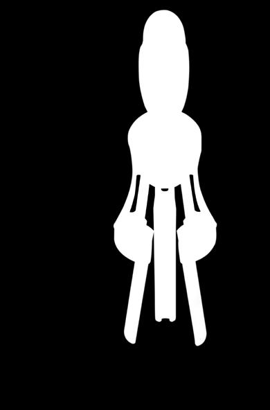
6 6 Timberline Lateral Fusion System Surgical Technique Guide PREOPERATIVE AND INTRAOPERATIVE PREPARATION NEUROMONITOR STATION C-ARM MONITOR C-ARM LIGHT SOURCE MAYO STAND ANESTHESIA Figure 1 OR layout Preoperative Preparation Review and inspect all instrumentation and implants prior to sterilization. The primary surgeon must be fully experienced with the required spinal fusion techniques, as well as the lateral surgical approach to the spine. Please read the Instructions for Use for a complete list of prescribing instructions. Surgical site access is dependent upon the level and indication(s) being treated. Adequate planning should be done to ensure safe and proper access to the surgical site. Preoperative imaging studies of the anatomy should be examined to: Ensure that the range of implant sizes is appropriate for the patient s anatomy at the proposed operative levels. Give special consideration to L4 L5, ensuring that height of the iliac crest will not prevent access to the L4 L5 disc space. Review anatomy and determine the best approach (i.e., left or right, concave vs. convex side of deformity). Tip: The Timberline angled instrument kit is available upon request. This kit may facilitate access to L4 L5 and other obstructed levels. Confer with the surgeon to ensure you have all of the needed implants (widths, lengths and heights) for the surgery. Intraoperative Preparation All imaging studies should be available for both planning and intraoperative review of the patient s anatomy. The Timberline System may be used alone or, at the surgeon s discretion, in conjunction with a neuromonitoring system. The Timberline System may be used with most other commercially available neuromonitoring systems. The operative suite should be laid out such that it is conducive to the lateral approach procedure (Figure 1).

7 Timberline Lateral Fusion System Surgical Technique Guide 7 PATIENT PREPARATION Neuromonitoring may be selected at the surgeon s discretion. If neuromonitoring is to be used, a neurophysiologist or neuromonitoring technician should apply electrodes to the patient prior to patient positioning. Tip: If neuromonitoring is selected, it is important to discuss with the anesthesiologist that the patient is not to be administered paralytics during the procedure. A train of four test will help ensure an absence of paralytics. STEP 1 Place the patient in a lateral decubitus (90 ) position on a breakable surgical table such that the patient s greater trochanter is directly over the break in the table. The surgical table should be reversed prior to positioning the patient so that fluoroscopy may be used (Figure 2). Tips: Considerations for left- vs. right-side positioning: When anatomy allows, a left-sided approach is preferred. Previous surgeries or anatomical factors may dictate approaching from the patient s right side. Use an auxiliary roll and hip bump underneath the patient s greater trochanter. Place pillows under the head, between the knees and under the upper arm. Cover sensitive areas as needed with a towel prior to taping. 3-inch silk surgical tape is recommended. Secure the patient to the table using surgical tape per the following (Figure 2): A. Directly across the table just below the tip of the iliac crest and below table break. B. Directly across the table, over the thoracic region just underneath the arm. C. Just superior and anterior to tip of the iliac crest, down to the foot of the table (posterior), around the corner of the table and back to the tip of the iliac crest. D. Just superior and posterior to tip of the iliac crest, down to the foot of the table (anterior), around the corner of the table and back to the tip of the iliac crest. E. From the tip of the iliac crest, straight down to the end of the table. F. From the anterior edge of the table, over the knee and along the lower leg to the posterior, inferior corner of the table. The pelvis should now be tilted away from the spine by lowering the table s foot end or the patient s legs. Figure 2 Patient positioning and taping
8 8 Timberline Lateral Fusion System Surgical Technique Guide NEUROMONITORING PREPARATION (if utilized) JOG IN PROBE CHANNEL PROBE CHANNEL PROBE Figure 3a Monopolar probe and initial dilator STEP 2 If neuromonitoring is selected by the surgeon, tape the blue end of the extension cable to the drape to keep it in the sterile field. Ensure that at least two feet of the extension cable s blue end is free for attachment to the stimulator probes. Connect the black end of the extension cable to the neuromonitoring system. Figure 3b Monopolar probe fully advanced in initial dilator STEP 4 A hard stop will indicate when the monopolar probe is fully advanced. Verify that the monopolar probe tip is fully advanced by ensuring that the distal tip is exposed (Figure 3b). Tip: It may be helpful to bend the proximal end of the monopolar probe out of the way to minimize interference with the K-wire and other instrumentation. STEP 3 If neuromonitoring is selected by the surgeon, insert a monopolar probe, or equivalent, into the exterior groove of the initial dilator. A jog in the initial dilator s probe channel provides resistance as the monopolar probe is advanced. This will keep the monopolar probe from backing out of the dilator as it passes through the soft tissue (Figure 3a).


9 Timberline Lateral Fusion System Surgical Technique Guide 9 RETRACTOR PREPARATION POSTERIOR HANDLE CRANIAL/CAUDAL HANDLE LOCKING COLLAR RETRACTOR BODY POSTERIOR ARM CRANIAL/CAUDAL ARMS Figure 4 Retractor components POSTERIOR HANDLE CRANIAL/CAUDAL HANDLE LOCKING COLLAR Figure 5 Handle assembly STEP 5 Attach the bedrail clamp to the bedrail on the anterior side of the patient. The bedrail clamp should be placed approximately one foot from the incision site, towards the head, ensuring that it is snug on the bedrail. STEP 7 Insert the posterior handle into the cranial/caudal handle. Ensure the posterior handle is pressed all the way into the cranial/caudal handle such that the second indicator line is flush with the cranial/caudal handle (Figure 5). STEP 6 After draping the patient, insert the articulating arm rod into the bedrail clamp. Ensure that enough of the articulating arm rod is exposed above the bedrail clamp for subsequent attachment of the articulating arm assembly to the retractor.


 for locking the handle")
10 10 Timberline Lateral Fusion System Surgical Technique Guide RETRACTOR PREPARATION (continued) ROTATE TO OPEN/CLOSE THE CRANIAL/ CAUDAL ARMS LOCKED Handle cannot be removed or rotated PARTIALLY LOCKED Handle is locked to the retractor body but can be rotated to open or close the cranial/caudal arms UNLOCKED Handle can be removed from the retractor body ROTATE TO OPEN/CLOSE THE POSTERIOR ARM ROTATE TO LOCK/UNLOCK THE HANDLE TO/FROM THE RETRACTOR BODY Figure 6 Locking collar positions STEP 8 Attach the handle assembly to the retractor body. You may need to twist the handle assembly while applying inward pressure to seat the handle assembly into the retractor body. Rotate the locking collar counterclockwise to secure the handle to the retractor body. There are alignment markings on the locking collar and cranial/caudal handle to indicate the partially locked position (as well as fully locked and unlocked positions) for locking the handle assembly to the retractor body (Figure 6). Figure 7 Retractor handle actuation STEP 9 Rotate the cranial/caudal handle clockwise to close the cranial/caudal arms. Rotate the posterior handle clockwise to close the posterior arm (Figure 7).
 are all the way down at the zero position.")

11 Timberline Lateral Fusion System Surgical Technique Guide 11 TOEING PAD IN TOED POSITION TOEING PAD IN ZERO POSITION Figure 8 Toeing pad position STEP 10 Ensure that both toeing pads (on the cranial/caudal arms) are all the way down at the zero position. Using the ball-tip driver or the second posterior handle provided in the kit, loosen the kit screws until the toeing pads are completely flush against the retractor body (Figure 8). Note: The toeing pads are adjusted via their respective 3.5mm hex kit screws. Similarly, the blades are attached with a 3.5mm hex kit screw. 3.5mm hex drivers are available on the ball-tip driver or the posterior handle. When the toeing pads are in the zero position, the cranial/caudal blades will not be in contact with each other, but rather will be slightly spaced apart.
 images may be obtained when the")


12 12 Timberline Lateral Fusion System Surgical Technique Guide SURGICAL APPROACH PREPARATION ANTERIOR MARGIN OF VB CENTER OF DISC SPACE POSTERIOR 1/3 OF DISC SPACE POSTERIOR MARGIN OF VB Figure 9 Examples of true lateral and A/P images STEP 11 Now that the patient has been secured to the table, adjust the table so that true lateral and anteriorposterior (A/P) images may be obtained when the C-arm is set at 90 and 0 respectively. Note: True A/P orientation of the surgical level has been achieved when the spinous process is centered directly between the pedicles, the pedicles appear round and the endplates are distinguished as a solid line on the A/P radiograph/fluoro. True lateral and A/P images may require adjusting the bed position separately for each level (Figure 9). True lateral orientation is noted by observing a sharp view of the endplates at the operative level and when the neural foramina align perfectly on the lateral radiograph/fluoro. Figure 10 Localization and incision site marking STEP 12 Identify the level to be fused by laying two crossed K-wires on the skin above the proposed surgical site. Confirm the position using fluoroscopy. The incision point for a single level should be centered over the disc of the level to be fused. For two levels, the incision point should be centered over the vertebral body, separating the two discs to be resected. Mark the incision point by marking the angle of the disc space, the anterior margin, posterior margin and midpoint to the posterior third of the disc space (Figure 10).

 into the free space of the")

13 Timberline Lateral Fusion System Surgical Technique Guide 13 SURGICAL APPROACH Figure 11 Approach to the spine STEP 13 After making the skin incision and dividing the subcutaneous tissue, the oblique muscles of the abdomen should be visible. Separate the fibers using blunt dissection. Once the retroperitoneal space has been entered, one should feel the tissue give way ( pop ) into the free space of the retroperitoneum. Move the peritoneum anteriorly with the forefinger and continue blunt dissection to palpate to the transverse process posteriorly. Slide the finger forward to the retro-psoas recess and over the dome of the psoas to ensure the retroperitoneal viscera have been safely retracted anteriorly (Figure 11).

14 14 Timberline Lateral Fusion System Surgical Technique Guide INITIAL DILATOR INSERTION Figure 12 Dilator insertion STEP 14 If neuromonitoring is selected by the surgeon, connect the blue end of the extension cable to the monopolar probe previously inserted into the initial dilator. STEP 15 While holding the index finger on the surface of the psoas muscle with the palm of the hand facing posteriorly, carefully guide the initial dilator down the palm of the hand and into the retroperitoneal space until the tip of the dilator is at the lateral margin of the psoas muscle (Figure 12). Remove the non-dominant hand and verify the position of the dilator using lateral fluoroscopy. Note: The dilator can be held in place with the initial dilator holder while using lateral fluoroscopy. Tip: The cranial/caudal position of the dilator should be the center of the disc space. The A/P position of the dilator should be between the posterior third and center of the disc space.


.")


15 Timberline Lateral Fusion System Surgical Technique Guide 15 DILATOR HOLDER DIRECTLY POSTERIOR Figure 13b Initial dilator holder Figure 13a Initial dilator placement STEP 16 Carefully advance the dilator through the psoas muscle using a rotating motion to ensure the dilator is all the way down to the disc, and to ensure there are no muscle fibers underneath the dilator (Figure 13a). Use the initial dilator holder to maintain the position of the dilator; confirm the dilator is still in an acceptable position using lateral fluoroscopy (Figures 13b, c, d). If the surgeon has elected to use neuromonitoring, the technician can initiate the EMG stimulation. The surgeon can then determine if the initial dilator is in a safe position relative to the nerves. Note: The initial dilator holder is designed with radiolucent tips to limit radiographic interference. Figure 13c Initial dilator holder lateral view Figure 13d Initial dilator holder lateral fluoro view

. Note: The K-wire has four markings.")

16 16 Timberline Lateral Fusion System Surgical Technique Guide K-WIRE INSERTION 4 TH MARKING INDICATES 30mm IN DISC SPACE Figure 14 Initial dilator and K-wire positioning STEP 17 Once the initial dilator is in an acceptable position, insert a K-wire through the center of the initial dilator and into the disc space. The K-wire should be inserted approximately halfway across the disc space to assist in securing the access entry point. Verify the position of the K-wire and initial dilator using A/P and lateral fluoroscopy (Figure 14). Note: The K-wire has four markings. The distal-most marking indicates when the K-wire is flush with the tip of the initial dilator. Each proximal marking thereafter indicates a distance of. Figure 15 Dilator depth measurement STEP 18 With the initial dilator fully advanced to the ipsilateral annulus of the disc, the retractor blade length can be chosen by noting the depth marked on the initial dilator at the skin edge (Figure 15). Tip: The blade length is measured from the bottom side of the retractor. Use the blade length one size longer than that indicated by the skin edge mark. The surgeon should immediately communicate the desired blade length to the technician to allow adequate time to assemble the blades onto the retractor before it is needed.

17 Timberline Lateral Fusion System Surgical Technique Guide 17 SECOND DILATOR INSERTION Figure 16 Second dilator placement STEP 19 If neuromonitoring is selected by the surgeon, keep the monopolar probe attached to the extension cable and remove the monopolar probe from the initial dilator. If desired by the surgeon, the monopolar probe may be inserted into the exterior groove of the second dilator. STEP 20 Carefully advance the second dilator over the initial dilator. Use a slow rotating motion to ensure the dilator has advanced all the way through the psoas and is down against the disc (Figure 16). If neuromonitoring is selected by the surgeon, and if desired, re-stimulate after the second dilator has been completely inserted to check for nearby nerves and help ensure the femoral nerve remains posterior to the dilators.
.")
.")
18 18 Timberline Lateral Fusion System Surgical Technique Guide RETRACTOR ASSEMBLY Figure 17a Retractor assembly Figure 17b Retractor assembly Figure 18 Blades attached to retractor STEP 21 With the retractor arms just slightly open, attach the posterior blade onto the posterior arm of the retractor using the ball-tip driver (Figure 17). Note: Retractor assembly should be performed on the back table while the surgeon is inserting the second dilator. To help ensure that the retractor is assembled when the surgeon is ready for it, assembly should begin immediately after determining the appropriate blade lengths (step 19). Tip: The cranial/caudal blades are identical and are not provided with any shims attached. The posterior blade is different, and is identified by a P marked on the side of the blade as well as by its integral and non-removable intradiscal shim. STEP 22 Next, attach the cranial/caudal blades onto the cranial/caudal arms of the retractor using the ball-tip driver (Figure 18).


19 Timberline Lateral Fusion System Surgical Technique Guide 19 Figure 19a Shim insertion Figure 19b Shim insertion Figure 19c Shim insertion Figure 20a Shim adjustment and removal Figure 20b Shim adjustment and removal Figure 20c Shim adjustment and removal Figure 20d Shim adjustment and removal STEP 23 If desired, manually load the lengthening shims into the cranial/caudal blades. Advance the shims using the shim impactor until they are flush with the tips of the blades. Tip: To ensure proper shim placement, place a finger at the end of the blade while inserting the shims into the cranial/caudal blades. The shim remover may be used to readjust the shims to the proper height. As described previously, the posterior blade is provided with an integrated intradiscal shim. Prior to handing the assembled retractor to the surgeon, ensure the posterior intradiscal shim is fully retracted and the blades are closed tightly (Figures 19, 20).


20 20 Timberline Lateral Fusion System Surgical Technique Guide RETRACTOR INSERTION ARTICULATING ARM PUTS DOWNWARD PRESSURE ON RETRACTOR TO ANTERIOR RAIL OF TABLE ATTACH HERE FOR ANTERIOR RETRACTION Figure 21 Retractor insertion ATTACH HERE FOR POSTERIOR BLADE RETRACTION Figure 22a Articulating arm attachment Figure 22b Articulating arm attachment points STEP 24 Carefully slide the retractor assembly over the second dilator using downward pressure and a gentle rotating motion. Align the retractor with the C-arm and verify the blades of the retractor are in line with the disc space using fluoroscopy. The retractor handle should be parallel to the disc space, and unless ribs or the iliac crest prevent it, the retractor working channel should be aligned with the disc space (Figure 21). Confirm correct positioning of the retractor using A/P and lateral fluoroscopy. STEP 25 Once the retractor is properly positioned, while maintaining downward pressure on the retractor, attach the articulating arm to the retractor body or posterior arm. The attachment choice will depend on the location of the dilator/k-wire in the disc space. To retract posteriorly with respect to the dilator, the articulating arm is attached to the retractor body; to retract anteriorly with respect to the dilator, the articulating arm is attached to the posterior arm (Figure 22). Verify the top surface of the retractor is parallel to the floor. Note: Attach the articulating arm in a triangular configuration, with the bend toward the ceiling, so that the assembly applies a downward force on the retractor. The black knob of the articulating arm should be above the level of the retractor.
.")
 can be used to verify the retractor is positioned correctly.")
21 Timberline Lateral Fusion System Surgical Technique Guide 21 Figure 23a Articulating arm knob Figure 23b Lateral fluoroscopy While applying downward pressure to the retractor, lock the articulating arm in the desired position. The articulating arm knob instrument may be used to tighten the articulating arm to the retractor (Figure 23a). Tip: It is helpful to support the weight of the articulating arm when attaching it to the retractor. Tip: Lateral fluoroscopy (Figure 23b) can be used to verify the retractor is positioned correctly. The fluoro image should allow the surgeon to see monopolar probe channels directly down the blades. The monopolar probe slots should be visible if the retractor is positioned parallel to the disc and in line with the C-arm.
 The Timberline retractor system design allows the surgeon to advance the intradiscal shim while the dilators are still in place.")

22 22 Timberline Lateral Fusion System Surgical Technique Guide INTRADISCAL SHIM EXTENSION OPTION 1 Figure 24a Monopolar probe in posterior blade Figure 24b Monopolar probe in second dilator Figure 24c Shim insertion STEP 26 (INTRADISCAL SHIM INSERTION OPTION 1) The Timberline retractor system design allows the surgeon to advance the intradiscal shim while the dilators are still in place. This helps to prevent the retractor from moving prior to fixing the position of the retractor relative to the spine using the shim. The surgeon may elect to confirm that the retractor is a safe distance from any neurological structures and deploy the intradiscal shim. Insert the monopolar probe into the groove in the posterior blade. Stimulate to determine relative proximity to nearby nerve roots (Figure 24a). Insert the monopolar probe back into the second dilator. Stimulate to determine to confirm the nerve is now farther away (Figure 24b). If the stimulation threshold increases, and the surgeon determines that the nerve is situated a safe distance from the posterior blade, the shim can now be deployed. Insert the shim impactor into the posterior blade. While confirming with A/P fluoroscopy, advance the intradiscal shim into the disc space until it bottoms out in the blade channel (Figure 24c). Tip: The force required to advance the shim is not significant. In many instances, this can be done by hand. If a mallet is required, the surgeon should refrain from impacting the shim with excessive force.
. Open the cranial/caudal blades by rotating the cranial/caudal handle counterclockwise approximately 180 (Figure 25).")

. To toe the blades outward, the handle is rotated clockwise.")
23 Timberline Lateral Fusion System Surgical Technique Guide 23 RETRACTION Figure 25 Cranial/caudal retraction STEP 27 Ensure that the locking collar is in the partially locked position so that the handle can be rotated (Refer to Figure 6 on page 10). Open the cranial/caudal blades by rotating the cranial/caudal handle counterclockwise approximately 180 (Figure 25). Note: A 180 turn of the cranial/caudal handle results in approximately 17mm of blade retraction. Figure 26 Plate toeing STEP 29 Retract anteriorly or posteriorly by rotating the posterior handle counterclockwise. STEP 30 Once the retractor has been opened to the desired position, remove the initial dilator and second dilator, leaving the K-wire in place. STEP 28 Toeing of the cranial/caudal blades may be accomplished using the posterior handle (Figure 26). To toe the blades outward, the handle is rotated clockwise. Tip: The cranial/caudal blades can be toed up to 20. Care should be taken to avoid trauma to the psoas and the radicular vessels located at the midpoint of the vertebral body. Blades should not be extended past the midpoint of either vertebral body.
 to the light cable. Attach the wave guide(s) to the desired cranial/caudal blades (Figure 27a).")


24 24 Timberline Lateral Fusion System Surgical Technique Guide WORKING CHANNEL PREPARATION Figure 27a Wave guide attachment Figure 27b Wave guide cover alignment Figure 28 Monopolar probe insertion STEP 31 Attach the wave guide(s) to the light cable. Attach the wave guide(s) to the desired cranial/caudal blades (Figure 27a). Turn on the light source and adjust the light intensity as needed. Tip: To ensure proper seating of the wave guide, place the wave guide onto the blade going straight down, ensuring the black cover sits inside the black channel (Figure 27b). STEP 32 If desired, and at the surgeon s discretion, the monopolar probe may be positioned into retractor blades to check for proximity to the neural elements. The cranial/caudal blades are designed with two channels in which the monopolar probe, or a similar probe, can be inserted (Figure 28). The posterior blade is designed with one center channel in which the monopolar probe, or a similar probe, can be inserted.
.")


25 Timberline Lateral Fusion System Surgical Technique Guide 25 Figure 29 Ball-tip probe Figure 30 Blade lengthening and widening shims STEP 33 Visualize and probe using the ball-tip probe to verify that the working area is clear of neural elements (Figure 29). STEP 34 A psoas retractor or Penfield may be used to sweep away any tissue from the working channel. Long suction instruments and bipolar forceps are available for this portion of the operation. Tip: Blade lengthening shims or widening shims may be utilized to extend the effective reach of the cranial and/or caudal blades and ensure tissues remain clear of the working area. Shims are loaded into the cranial/caudal blades with the shim inserter. Insert the shims down the center channel of the cranial and/or caudal blades. The posterior blade has a preloaded, non-removable intradiscal shim.
 If the surgeon selects to open the retractor prior to shim insertion with the dilators still in place (step 26 on page 22) do the following: Extend the")

26 26 Timberline Lateral Fusion System Surgical Technique Guide INTRADISCAL SHIM EXTENSION OPTION 2 SHIM IS ALL THE WAY DOWN Figure 31 Advance shim Figure 32 Intradiscal shim position STEP 35 (INTRADISCAL SHIM INSERTION OPTION 2) If the surgeon selects to open the retractor prior to shim insertion with the dilators still in place (step 26 on page 22) do the following: Extend the intradiscal shim of the posterior blade into the intervertebral disc space from its initial position using the shim inserter (Figure 31). As needed, impact the shim inserter until the intradiscal shim bottoms out in the blade channel. When fully seated, the intradiscal shim will be protruding 20mm past the blade tip. Verify the intradiscal shim location using anterior/ posterior fluoroscopy (Figure 32). Remove the K-wire. Tip: The force required to advance the shim is not significant. In many instances, this can be done by hand. If a mallet is required, the surgeon should refrain from impacting the shim with excessive force.


27 Timberline Lateral Fusion System Surgical Technique Guide 27 CORRECT ACCESS CONFIRMATION AND ANTERIOR BLADE ATTACHMENT Figure 33 Scoville with crossbar STEP 36 Confirm that the retractor has been opened to the desired exposure. Tip: An implant trial or box cutter may be placed into the working channel to verify there is adequate room for the procedure. Lateral fluoroscopy can be used to confirm proper alignment of the templating instrument with the disc space. If desired, unlock the retractor handle and remove it from the retractor body. STEP 37 The surgeon has the option to utilize a soft tissue retractor to help retract soft tissue between the cranial/caudal blades, anteriorly. This soft tissue retractor also helps to identify the location of the anterior margin of the vertebral body. Place the tip of the soft tissue retractor just anterior to the anterior longitudinal ligament under direct visualization. Clip the anterior bar into the front of the retractor. Place the shaft of the soft tissue retractor within the hook of the anterior bar and tighten the thumb wheel such that it holds the soft tissue retractor shaft firmly. Note: There are five variations of soft tissue retractors with varying lengths, blade curvatures and blade widths in the Timberline System kit.
. Care is taken to avoid traversing the anterior longitudinal ligament and the anteriorly situated vessels.")

28 28 Timberline Lateral Fusion System Surgical Technique Guide ANNULOTOMY AND DISCECTOMY Figure 34 Annulotomy STEP 38 Having first defined the anterior border of the disc space, use the bayoneted annulotomy knife to cut the annulus (Figure 34). Care is taken to avoid traversing the anterior longitudinal ligament and the anteriorly situated vessels. The annulotomy should be at least as long as the width of the implant to be used (i.e., 16mm, 1, 22mm, 26mm). Figure 35a Cobb elevator STEP 39 Use a straight cobb elevator to disrupt the disc from both vertebral endplates and release the contralateral annulus. This will allow for an implant to sit on the contralateral apophyseal ring. Confirm under radiographic evaluation. Box cutters, pituitary rongeurs, curettes, ring curettes and rasps can be used to resect the disc material and prepare the bony endplates for fusion.


 to distract the vertebral bodies.")


29 Timberline Lateral Fusion System Surgical Technique Guide 29 Figure 35b Disc box cutter Figure 35c Pituitary rongeur Figure 35d Trial rasp If needed, use disc spreaders (with the straight modular handle or the T-handle) to distract the vertebral bodies. Note: Avoid unintentional resection of the anterior longitudinal ligament or violation of the bony endplate (Figure 35). Note: The rongeurs and implantation instruments kit is equipped with a slap hammer which may be used in conjunction with any modular or handled instrument.


30 30 Timberline Lateral Fusion System Surgical Technique Guide IMPLANT SIZING AND INSERTION 60mm 50mm 40mm 40mm 50mm 60mm Figure 36a Trial placement Figure 36b Implant sizing STEP 40 Use trials to determine the correct implant size. Note: Trials for each implant width, lordotic angle and height are provided in the kit. Start with the smallest size trial and move up in size as needed. Confirm correct placement of the trial using lateral and A/P fluoroscopy. The trial should be centered across the disc space and appropriately centered in the anterior/posterior plane. Implant length can be determined using the holes in the trial. Holes are placed, 40mm, 50mm and 60mm from the tip of the trial (Figures 36a, b). The slap hammer may be used to assist with removal of spreaders or trials.
31 Timberline Lateral Fusion System Surgical Technique Guide 31 ANTERIOR POSTERIOR Figure 37 Implant and inserter STEP 41 Select the corresponding size Timberline implant. Pack the implant with bone graft, being careful not to over pack the implant. Attach the implant to the inserter. There are two locating pins that help center the inserter draw rod over the insertion hole of the implant. Rotate the thumb wheel clockwise until the implant is securely attached to the inserter (Figure 37). Attach the inserter to a modular T-handle. Note: Standard implants are available in 1 or 22mm widths, 40mm 60mm lengths and 0 or 8 lordotic configurations (see pages for additional implant size options). Note: The implant inserter and implant trials are marked with the letter P to designate the posterior position as it relates to the posterior aspect of the implant.

.")

32 32 Timberline Lateral Fusion System Surgical Technique Guide IMPLANT SIZING AND INSERTION (continued) Figure 38b Implant placement Figure 38a Implant insertion STEP 42 Carefully impact the implant into the disc space. Fluoroscopy should be used to confirm correct implant placement. The implant should traverse the apophyseal ring and be centered within the disc space (Figure 38). Tip: If between lengths, it is always better to size up to ensure the implant spans the apophyseal ring. STEP 43 Remove the inserter from the implant and verify the final position of implant with fluoroscopy. Ensure that no graft material has extruded out of the implant s graft chamber. Adjust with the implant impactor as necessary. Figure 38c Lateral view, implant placement confirmation
33 Timberline Lateral Fusion System Surgical Technique Guide 33 INSTRUMENT REMOVAL AND CLOSURE STEP 44 Retract the intradiscal shim into the posterior blade using the shim remover/retractor. Remove the scoville retractor and anterior crossbar attachment. Remove the light wave guides. Remove all other shims in the cranial/caudal blades. If the cranial/caudal blades were toed, return them to the zero position. Attach the handle assembly to the retractor body if previously detached. Close the retractor. Loosen the black articulating arm knob and disconnect the arm from the retractor by loosening the thumb screw. Carefully remove the retractor while watching to ensure there is no excess bleeding. The Timberline System is indicated for use with supplemental fixation. STEP 45 The wound is closed using standard techniques. REMOVAL OR REVISION PROCEDURE OF THE TIMBERLINE IMPLANT (if necessary) 1. Attach the implant inserter or implant remover to remove the implant. 2. Attach a slap hammer to the instrument or use a mallet to tap the instrument until the implant is removed from the disc space.
34 34 Timberline Lateral Fusion System Surgical Technique Guide TIMBERLINE IMPLANT SIZES AND GRAFT VOLUMES Standard Sizes, PCR width, 0 lordosis 1 40mm mm mm mm mm 0 1 width, 8 lordosis 1 45mm mm mm mm 8 HEIGHT cc HEIGHT cc 16mm mm width, 0 lordosis 22mm 45mm 0 22mm 50mm 0 22mm 55mm 0 22mm 60mm 0 22mm width, 8 lordosis 22mm 45mm 8 22mm 50mm 8 22mm 55mm 8 22mm 60mm 8 HEIGHT cc HEIGHT cc 16mm
35 Timberline Lateral Fusion System Surgical Technique Guide 35 PCR mm width, 0 lordosis HEIGHT cc 16mm 25mm 0 16mm 30mm 0 16mm 35mm 0 16mm 40mm 0 6mm 6mm 6mm 6mm PCR width, 0 lordosis, coronal taper 4 HEIGHT cc 1 45mm 0, CT 1 50mm 0, CT 1 55mm 0, CT 1 60mm 0, CT PCR mm width, 0 lordosis HEIGHT cc 26mm 45mm 0 26mm 50mm 0 26mm 55mm 0 26mm 60mm width, 8 lordosis, coronal taper mm 8, CT 1 50mm 8, CT 1 55mm 8, CT 1 60mm 8, CT HEIGHT cc 16mm mm width, 8 lordosis HEIGHT cc 26mm 45mm 8 26mm 50mm 8 26mm 55mm 8 26mm 60mm 8 16mm
36 36 Timberline Lateral Fusion System Surgical Technique Guide TIMBERLINE IMPLANT SIZES AND GRAFT VOLUMES (continued) Non-Standard Sizes 1 width, 0 lordosis 1 40mm mm mm mm mm 0 1 width, 8 lordosis 1 40mm mm mm mm 0 HEIGHT cc 16mm 16mm 16mm 16mm 16mm HEIGHT cc 16mm 16mm 16mm 16mm mm width, 0 lordosis HEIGHT cc 22mm 45mm 0 22mm 50mm 0 22mm 55mm 0 22mm 60mm 0 22mm width, 8 lordosis HEIGHT cc 22mm 45mm 8 22mm 55mm 8 22mm 60mm 8 16mm 16mm 16mm 16mm 16mm 16mm 16mm


37 Timberline Lateral Fusion System Surgical Technique Guide 37 RADIOGRAPHIC MARKER POSITIONS AND KIT OVERVIEW A/P VIEW 2.0 WIDTH LATERAL VIEW HEIGHT LENGTH Standard Implant and Instrument Kits Auxiliary Implant and Instrument Kits Disposable Kits DESCRIPTION Timberline Case 1, 1 and 22mm Implant Kit Timberline Case 2, Retractor Kit I Timberline Case 3, Retractor Kit II Timberline Case 4, Disc Preparation Kit Timberline Case 5, Rongeur and Implantation Instruments Timberline Case 6, Auxiliary Instruments Timberline Case 7, Angled Instruments Timberline 16mm Implant Kit Timberline 26mm Implant Kit Timberline Coronal Taper Implant Kit Timberline Access Kit Timberline Monitoring Kit* Special Order MEP Electrode Kit PCR PCR PCR PCR PCR PCR PCR PCR PCR PCR *May not be available in all geographic areas.

38 38 Timberline Lateral Fusion System Surgical Technique Guide STANDARD IMPLANT AND INSTRUMENT KITS Timberline Case 1: 1 and 22mm Implant Kit, PCR Trial width, 0 lordosis mm width, 0 lordosis width, 8 lordosis mm width, 8 lordosis Timberline Case 2: Retractor Kit I, PCR Retractor Cranial/Caudal Blades 50mm mm mm mm mm mm mm mm mm mm mm mm mm Cranial/Caudal Handle Posterior Handle Posterior Blades 50mm mm mm mm mm mm mm mm mm mm mm mm mm
39 Timberline Lateral Fusion System Surgical Technique Guide 39 Timberline Case 2: Retractor Kit I, PCR (continued) Anterior Bar Shim Remover Soft Tissue Retractor, Reverse 140mm mm Threaded Shim Extended, 5mm Soft Tissue Retractor, Narrow Reverse 140mm mm Anchoring Screw Soft Tissue Retractor, Long Threaded Shim Driver Lengthening Shim Threaded Shim Sleeve Widening Shims Right Left Ball-Tip Driver Shim Inserter/Impactor Top Handle Inner Outer
40 40 Timberline Lateral Fusion System Surgical Technique Guide STANDARD IMPLANT AND INSTRUMENT KITS (continued) Timberline Case 3: Retractor Kit II, PCR Initial Dilator Second Dilator Suction Instrument 12FR Short FR Long Blunt Bayoneted Dissector, Penfield 4mm Reverse 4mm Initial Dilator Holder Modulator Instrument Blunt K-wire Chamfered K-wire K-wire Dispenser Psoas Retractor 4mm, Right Hand , Right Hand mm, Left Hand , Left Hand Articulating Arm Knob Bipolar Forceps Table Clamp Articulating Arm
41 Timberline Lateral Fusion System Surgical Technique Guide 41 Timberline Case 4: Disc Preparation Kit, PCR Osteotome Box Curette 7mm Curved Osteotome Cobb Elevator mm Angled Cobb Elevator mm Serrated Cup Curette, Straight 2mm mm mm Serrated Cup Curette, Angled Up 2mm mm Endplate Scraper (Pull)

42 42 Timberline Lateral Fusion System Surgical Technique Guide STANDARD IMPLANT AND INSTRUMENT KITS (continued) Timberline Case 5: Rongeur and Implantation Instruments, PCR Ferris Smith Pituitary Rongeur 3mm mm mm Box Osteotome, 1 4mm mm Box Osteotome, 22mm 4mm mm Hodgson-style Rongeur 7mm Trial Rasp, 1 width, 0 lordosis 6mm Kerrison Rongeur 3mm mm T-handle Slap Hammer Straight Modular Handle

43 Timberline Lateral Fusion System Surgical Technique Guide 43 Timberline Case 5: Rongeur and Implantation Instruments, PCR (continued) Slap Hammer Adaptor Inserter Spanner Wrench Implant Inserter or Thin Disc Spreader, 1 x 4mm Draw Rod or Thick Disc Spreader,1 x 6mm Impactor Implant Remover Piece Graft Slider
44 44 Timberline Lateral Fusion System Surgical Technique Guide STANDARD IMPLANT AND INSTRUMENT KITS (continued) Timberline Case 6: Auxiliary Instrument Kit, PCR Paddle Shaver 6mm mm Rotating Disc Cutter 6mm mm Disc Spreader 6mm mm
45 Timberline Lateral Fusion System Surgical Technique Guide 45 Timberline Case 7: Angled Instrument Kit, PCR Ferris Smith Pituitary Rongeur, Angled 5mm, Right mm, Left mm, Right mm, Left Cobb, Angled Up mm Box Chisel, Angled 4mm mm Trial Rasp, Angled, 1 6mm Cobb, Angled Down mm Trial, Angled, Serrated Cup Curette, Angled Up 4mm Serrated Cup Curette, Angled Down 4mm
46 46 Timberline Lateral Fusion System Surgical Technique Guide STANDARD IMPLANT AND INSTRUMENT KITS (continued) Timberline Case 7: Angled Instrument Kit, PCR (continued) Endplate Scraper, Angled Implant Inserter, Angled Right Left Disc Spreader, Angled 4mm mm Impactor, Angled


47 Timberline Lateral Fusion System Surgical Technique Guide 47 DISPOSABLE KITS Timberline Access Kit, PRODUCT DESCRIPTION QUANTITY Annulotomy Knife Wave Guide Timberline Monitoring Kit, (May not be available in all geographic areas.) Note: includes both and (next page). Alternatively, or may be ordered individually. Probe and Connector Box, PRODUCT DESCRIPTION QUANTITY Detachable Monopolar Probes, 275mm Probe Extension Cables Ball-tip Probe
 Lead Wire Pair Surface Electrodes, 2.5m, 1.5cm x 2cm 4 8735-1012-(009 012) Lead Wire Single Needles, 2.")
48 48 Timberline Lateral Fusion System Surgical Technique Guide DISPOSABLE KITS (continued) Timberline Monitoring Kit, (continued) EMG/SSEP Electrode Kit, PRODUCT DESCRIPTION QUANTITY Lead Wire Parallel Pair Subdermal Needles, 2.5m ( ) Lead Wire Pair Surface Electrodes, 2.5m, 1.5cm x 2cm ( ) Lead Wire Single Needles, 2.5m ( ) Lead Wire, 2.5m, 19mm Single Needle Lead Wire Ground Electrode, 2.5m (Single Surface Electrode) Lead Wire Return Electrode, 2.5m (Single Surface Electrode) Gauze Pads Alcohol Pads Roll of Tape Marking Pen Special Order MEP Electrode Kit, PRODUCT DESCRIPTION QUANTITY Lead Wire Parallel Pair Subdermal Needles, 2.5m Lead Wire Parallel Pair Subdermal Needles, 2.5m Corkscrew Corkscrew
49 Timberline Lateral Fusion System Surgical Technique Guide 49 IMPORTANT INFORMATION ON THE TIMBERLINE LATERAL FUSION SYSTEM Device Description The Timberline Lateral Fusion System is an intervertebral body fusion/vertebral body replacement device generally consisting of a rectangular shape with various lengths, widths, heights and lordotic angles, which may incorporate a measuring function and has uses as described on the label. The device has a hollowed out central area to accommodate autogenous bone graft. The upper and lower surfaces have a series of transverse grooves formed to improve stability and fixation once the device is inserted. The Timberline device is available in a variety of sizes and configurations to approximate anatomical variation in different vertebral levels and/or patient anatomy. The Timberline System includes disc prep and general instruments, a retractor system and several associated disposables. The Timberline System consists of a comprehensive kit of instruments to perform the surgery. The retractor system consists of three blades with an optional fourth blade attachment. The posterior blade moves independently with respect of the cranial/caudal blades. Multiple blade lengths are available. Other features include toeing blades up to 20, controlled opening/closing of the arms with infinite resolution, intradiscal docking shims, blade widening and lengthening shims, and fiber optic illumination. Zimmer Biomet Spine provides separate disposable kits for accessing the disc space or for help with neuromonitoring. Indications for Use When used as a lumbar intervertebral body fusion device, the Timberline System is intended for spinal fusion procedures to be used with autogenous bone graft in skeletally mature patients with degenerative disc disease (DDD) at one or two contiguous spinal levels from L2 S1. DDD is defined as discogenic back pain with degeneration of the disc confirmed by history and radiographic studies. These patients should have had six months of non-operative treatment. These DDD patients may have had a previous non-fusion spinal surgery at the involved spinal level(s), and may have up to Grade 1 spondylolisthesis or retrolisthesis at the involved level(s). The Timberline System is to be combined with supplemental fixation. Approved supplemental fixation systems include the Zimmer Biomet Spinal Fixation System. The following devices are indicated to be used as a lumbar intervertebral body fusion device: When used as a vertebral body replacement, the Timberline System is indicated for use to replace a vertebral body that has been resected or excised due to tumor or trauma/ fracture. The device is intended for use as a vertebral body replacement in the thoracolumbar spine (from T1 L5). The Timberline System may also be used in the thoracolumbar spine (i.e., T1 L5) for partial replacement (i.e., partial vertebrectomy) of a diseased vertebral body resected or excised for the treatment of tumors in order to achieve anterior decompression of the spinal cord and neural tissues, and to restore the height of a collapsed vertebral body. The Timberline device is also indicated for treating fractures of the thoracic and lumbar spine. The Timberline System is designed to restore the biomechanical integrity of the anterior, middle and posterior spinal column. For either indication, the system must be used with supplemental internal fixation. Supplemental internal fixation is required to properly utilize this system. The following devices are indicated to be used as a vertebral body replacement (VBR) device: Description Length Range Width Range Height Range Lordotic Angles Timberline 25mm 60mm 16mm,1, 6mm 50mm 0 and 8 22mm and 26mm For any of the above indications, the system must be used with supplemental internal fixation. Contraindications Contraindications include, but are not limited to: Presence of fever or infection (systemic, spinal or localized). Pregnancy. Severe osteopenia. Prior fusion at the level to be treated. Any condition not described in the Indications for Use. Any other medical or surgical condition which would preclude the potential benefit of spinal implant surgery. Patients with metal sensitivity or allergies to the implant materials. Patients unwilling or unable to cooperate with postoperative care instructions. Description Length Range Width Range Height Range Lordotic Angles Timberline 25mm 60mm 16mm,1, 6mm 16mm 0 and 8 22mm and 26mm
Imola Lateral IBF System Surgical Technique
 Imola Lateral IBF System Surgical Technique IMOLA CIRCUIT TABLE OF CONTENTS Design Rationale Instructions for Use Surgical Technique 1. Table Mounting 2. Surgical Planning & Targeting 3. Access and Preparation
Thoracolumbar Solutions. Timberline MPF. Lateral Modular Plate Fixation System. Surgical Technique Guide
 Thoracolumbar Solutions Timberline MPF Lateral Modular Plate Fixation System Surgical Technique Guide Timberline MPF Lateral System Surgical Technique Guide A first-of-its-kind, lateral, modular plate
nvt Transforaminal Lumbar Interbody Fusion System
 nvt Transforaminal Lumbar Interbody Fusion System 1 IMPORTANT INFORMATION FOR PHYSICIANS, SURGEONS, AND/OR STAFF The nv a, nv p, and nv t are an intervertebral body fusion device used in the lumbar spine
nvp Posterior Lumbar Interbody Fusion System
 nvp Posterior Lumbar Interbody Fusion System 1 IMPORTANT INFORMATION FOR PHYSICIANS, SURGEONS, AND/OR STAFF The nv a, nv p, and nv t are an intervertebral body fusion device used in the lumbar spine following
nva Anterior Lumbar Interbody Fusion System
 nva Anterior Lumbar Interbody Fusion System 1 IMPORTANT INFORMATION FOR PHYSICIANS, SURGEONS, AND/OR STAFF The nv a, nv p, and nv t are an intervertebral body fusion device used in the lumbar spine following
Solitaire Anterior Spinal System
 Surgical Technique Solitaire Anterior Spinal System Independent Stabilization for the Anterior Column Available in Titanium and Contents Introduction... Page 1 Design Features... Page 2 Instruments...
BAK/C Cervical Anterior Interbody Fusion System
 Surgical Technique BAK/C Cervical Anterior Interbody Fusion System The Comfortable Choice for Cervical Fusion BAK/C Cervical Surgical Technique 1 The BAK/C Cervical Fusion System is an alternative to conventional
Posterior Lumbar Interbody Fusion System
 Px Posterior Lumbar Interbody Fusion System Px PEEK INTERBODY FUSION SYSTEM INDICATIONS FOR USE The Innovasis Px PEEK IBF System is an intervertebral body fusion device for use in patients with degenerative
EXACTECH SPINE. Operative Technique. Cervical Spacer System. Surgeon focused. Patient driven. TM
 EXACTECH SPINE Operative Technique Cervical Spacer System Surgeon focused. Patient driven. TM ACAPELLA ONE Acapella One Cervical Spacer System is an anterior cervical discectomy and fusion device with
Technique Guide. Oracle Spacer System. Instruments and implants for a direct lateral approach to the lumbar spine.
 Technique Guide Oracle Spacer System. Instruments and implants for a direct lateral approach to the lumbar spine. Table of Contents Introduction Oracle Spacer System 2 AO Principles 4 Indications 5 Surgical
SURGICAL TECHNIQUE MANUAL. InterFuse T
 1 CONTENTS InterFuse T Product Description 3 Indications for Use 3 X-Ray Marker Locations 4 Product Specifications 4 Instrument Set 5 Step 1 Preoperative Planning 8 Patient Positioning 8 Step 2 Disc Removal
PILLAR AL. Anterior Lumbar Interbody Fusion (ALIF) and Partial Vertebral Body Replacement (pvbr) PEEK Spacer System OPERATIVE TECHNIQUE
 and Partial Vertebral Body Replacement (pvbr) PEEK Spacer System OPERATIVE TECHNIQUE") PILLAR AL PEEK Spacer System Anterior Lumbar Interbody Fusion (ALIF) and Partial Vertebral Body Replacement (pvbr) OPERATIVE TECHNIQUE Table of Contents 1 INTRODUCTION 2 PRE-OPERATIVE TECHNIQUE 3 OPERATIVE
PILLAR AL PEEK Spacer System Anterior Lumbar Interbody Fusion (ALIF) and Partial Vertebral Body Replacement (pvbr) OPERATIVE TECHNIQUE Table of Contents 1 INTRODUCTION 2 PRE-OPERATIVE TECHNIQUE 3 OPERATIVE
VTI INTERFUSE T SURGICAL TECHNIQUE FORWARD THINKING FOR THE BACK. 1/20
 VTI INTERFUSE T SURGICAL TECHNIQUE FORWARD THINKING FOR THE BACK. 1/20 CONTENTS InterFuse T Product Description Indications for Use X-Ray Marker Locations Product Specifications Instrument Set 3 4 5 STEP
Surgical Technique. TraXis. Precision. Transforaminal Lumbar Interbody Fusion Spacer. The Art & Science of Spine Surgery
 Surgical Technique Precision TraXis Transforaminal Lumbar Interbody Fusion Spacer The Art & Science of Spine Surgery Table of Contents Introduction 3 Indications 4 Key Instruments 5 Surgical Technique
CROSS -FUSE P E E K V B R / I B F SYST E M
 S U R G I C A L T E C H N I Q U E CROSS -FUSE P E E K V B R / I B F SYST E M S U R G I C A L S Y S T E M O V E R V I E W 2 CROSS-FUSE P E E K V B R / I B F S Y S T E M S U R G I C A L T E C H N I Q U E
Alamo T Transforaminal Lumbar Interbody System Surgical Technique
 Transforaminal Lumbar Interbody System Surgical Technique Table of Contents Indications and Device Description.............. 1 Alamo T Implant Features and Instruments...........2 Surgical Technique......................
VTI INTERFUSE S SURGICAL TECHNIQUE FORWARD THINKING FOR THE BACK.
 VTI INTERFUSE S SURGICAL TECHNIQUE FORWARD THINKING FOR THE BACK. CONTENTS InterFuse S Product Description Indications for Use X-Ray Marker Locations and Product Specifications Instrument Set 3 4 5-7 STEP
Royal Oak IBFD System Surgical Technique Posterior Lumbar Interbody Fusion (PLIF)
") Royal Oak IBFD System Surgical Technique Posterior Lumbar Interbody Fusion (PLIF) Preoperative Planning Preoperative planning is necessary for the correct selection of lumbar interbody fusion devices.
Royal Oak IBFD System Surgical Technique Posterior Lumbar Interbody Fusion (PLIF) Preoperative Planning Preoperative planning is necessary for the correct selection of lumbar interbody fusion devices.
C-THRU Anterior Spinal System
 C-THRU Anterior Spinal System Surgical Technique Manufactured From Contents Introduction... Page 1 Design Features... Page 2 Instruments... Page 3 Surgical Technique... Page 4 Product Information... Page
TECHNICAL BROCHURE. Capture Facet Fixation System
 TECHNICAL BROCHURE Capture Facet Fixation System Table of Contents Product Overview...2 Instruments...4 Capture Facet Screw Surgical Technique Patient Preparation and Positioning...6 Guide Pin Placement...7
OPERATIVE TECHNIQUE COVER IMAGE OPTIONAL (DETAIL) IMAGE SKYHAWK. lateral interbody fusion system lateral plate system
 IMAGE SKYHAWK. lateral interbody fusion system lateral plate system") OPERATIVE TECHNIQUE COVER IMAGE OPTIONAL (DETAIL) IMAGE SKYHAWK lateral interbody fusion system lateral plate system TABLE OF CONTENTS Introduction 1 Pre-Operative Technique 2 Operative Technique 3 Part
OPERATIVE TECHNIQUE COVER IMAGE OPTIONAL (DETAIL) IMAGE SKYHAWK lateral interbody fusion system lateral plate system TABLE OF CONTENTS Introduction 1 Pre-Operative Technique 2 Operative Technique 3 Part
Advantage ALIF. Keith Shevlin Managing Director
 Advantage ALIF Unit 10, 9-11 Myrtle Street, Crows Nest NSW 2065 Keith Shevlin Managing Director keithshevlin@precisionsurgical.com.au Advantage ALIF Introduction & Indications for Use 1 Surgical Technique
Surgical Technique Manual
 InterFuse S Interbody Fusion System Surgical Technique Manual VERTEBRAL TECHNOLOGIES MS 4043-02 Rev. O Product Overview Introduction The VTI InterFuse S implant is an interbody fusion device that combines
M.I.S. MAKE IT SMART IN ONE SYSTEM. Surgical Technique. Hip Knee Spine Navigation
 M.I.S. MAKE IT SMART IN ONE SYSTEM Surgical Technique Hip Knee Spine Navigation M.U.S.T. Mini Open Surgical Technique Hip Knee Spine Navigation 2 C O N T E N T S 1 INTRODUCTION 4 2 SURGICAL TECHNIQUE 5
Cervical Spacer System surgical technique
 Blackhawk TM Cervical Spacer System surgical technique Blackhawk TM The BLACKHAWK Cervical Spacer System is designed to provide biomechanical stabilization as an adjunct to fusion. Spinal fixation should
LUMBAR POSTERIOR MINIMALLY INVASIVE SYSTEM. Surgical Technique
 LUMBAR POSTERIOR MINIMALLY INVASIVE SYSTEM Surgical Technique Joint Spine Sports Med M.U.S.T. Mini Open Surgical Technique Joint Spine Sports Med CAUTION Federal law (USA) restricts this device to sale
Veyron -C Anterior Cervical System Surgical Technique
 Veyron -C Anterior Cervical System Surgical Technique 2 Veyron-C Anterior Cervical System Surgical Technique Veyron-C Anterior Cervical System Surgical Technique Description, Indications & Contraindications...3
Thoracolumbar Solutions. Zyston Curve. Interbody Spacer System. Surgical Technique Guide
 Thoracolumbar Solutions Zyston Curve Interbody Spacer System Surgical Technique Guide 2 Zyston Curve Interbody Spacer System Surgical Technique Guide The Zyston Curve Interbody System is designed to optimize
EFSPINE CERVICAL COMBINED SET DISC PROTHESIS ORGANIZER BOX
 EFSPINE CERVICAL COMBINED SET INSTRUMENTS CERVICAL CAGE & DISC PROTHESIS ORGANIZER BOX Cervical Thoracic Thoraco - Lumbar Sacral EFSPINE CERVICAL COMBINED SET CERVICAL IMPLANTS INTRODUCTION Cervical Disc
Fusion Device. Surgical Technique. Cervical Interbody Fusion with Trabecular Metal Technology
 TM-S Fusion Device Surgical Technique Cervical Interbody Fusion with Trabecular Metal Technology 2 TM-S Fusion Device Surgical Technique Disclaimer This surgical technique is not intended for use in the
Alamo C. Cervical Interbody System Surgical Technique. An Alliance Partners Company
 Cervical Interbody System Surgical Technique Table of Contents Indications for Use................................1 Device Description............................... 1 Alamo C Instruments..............................
HawkeyeTM Peek. surgical technique
 HawkeyeTM Peek surgical technique Introduction The ChoiceSpine HAWKEYE Vertebral Body Replacement (VBR) System is intended for use in the thoracolumbar spine (T1 - L5) to replace a collapsed, damaged,
Transforaminal Lumbar Interbody Fusion Cage (TLIF)
") Transforaminal Lumbar Interbody Fusion age (TLIF) 990100010 DOULE ENGINE MEDIL MTERIL O., LTD. No. 218 Houxiang Road, Haicang District, Xiamen 361022, P.R.hina Tel: +86 592 6087101 Fax: +86 592 6587078
Transforaminal Lumbar Interbody Fusion age (TLIF) 990100010 DOULE ENGINE MEDIL MTERIL O., LTD. No. 218 Houxiang Road, Haicang District, Xiamen 361022, P.R.hina Tel: +86 592 6087101 Fax: +86 592 6587078
product overview Implant heights range from 8mm-20mm in 2mm increments, with two lordocic angle options of 6 and 12.
 ETHOS A-Spacer PEEK System Surgical Technique Guide Synchronizing Medical Innovation with Global Markets product overview The SyncMedical Ethos PEEK IBF System is an intervertebral body fusion device for
T-PAL. Transforaminal Posterior Atraumatic Lumbar Cage System.
 T-PAL. Transforaminal Posterior Atraumatic Lumbar Cage System. Technique Guide This publication is not intended for distribution in the USA. Instruments and implants approved by the AO Foundation. Image
EIT TLIF Cage. For Natural Bone Ingrowth with EIT Cellular Titanium
 EIT TLIF Cage For Natural Bone Ingrowth with EIT Cellular Titanium EIT TLIF Cage Surgical Technique EIT Cellular Titanium provides active fusion area» ~ 80% porosity» ~ 650 µm diamond pore size» open interconnected
TABLE OF CONTENTS. ShurFit Anterior Cervical Interbody Fusion (ACIF) System Overview 2. Implant Specifications 3. Instrument Features 4
 System Overview 2. Implant Specifications 3. Instrument Features 4") Surgical Technique TABLE OF CONTENTS ShurFit Anterior Cervical Interbody Fusion (ACIF) System Overview 2 Product Highlights 2 Indications 2 Implant Specifications 3 Instrument Features 4 Surgical Technique
Surgical Technique TABLE OF CONTENTS ShurFit Anterior Cervical Interbody Fusion (ACIF) System Overview 2 Product Highlights 2 Indications 2 Implant Specifications 3 Instrument Features 4 Surgical Technique
Threshold Pedicular Fixation System Surgical Technique
 Threshold Pedicular Fixation System Surgical Technique Table of Contents Patient Preparation and Positioning... 2 Determining Incision Location... 3 Assembling the Cannulated Awl... 4 Guide Wire Placement...
Interbody fusion cage for the transforaminal approach. Travios. Surgical Technique
 Interbody fusion cage for the transforaminal approach Travios Surgical Technique Image intensifier control This description alone does not provide sufficient background for direct use of DePuy Synthes
MODULAR DESIGN OFFERS FREEDOM OF CHOICE. Surgical Technique
 MODULAR DESIGN OFFERS FREEDOM OF CHOICE Surgical Technique Joint Spine Sports Med MectaLIF Anterior Surgical Technique 2 INDEX 1. INTRODUCTION 4 1.1 Material & Marker 5 2. INDICATIONS 5 3. CONTRAINDICATIONS
INSIGHT LATERAL ACCESS SYSTEM Minimal invasive access system for the thoracolumbar spine.
 INSIGHT LATERAL ACCESS SYSTEM Minimal invasive access system for the thoracolumbar spine. Instruments and implants approved by the AO Foundation. This publication is not intended for distribution in the
Surgical technique. SynCage-C short
 Surgical technique SynCage-C short Table of contents Implants 2 Indications/contra-indications 3 Surgical technique 4 Image intensifier control Warning This description is not sufficient for immediate
Surgical Technique. LLIF Procedure. Lateral Lumbar Interbody Fusion. with MARS 3V & TransContinental
 Surgical Technique LLIF Procedure Lateral Lumbar Interbody Fusion with MARS 3V & TransContinental At Globus, we move with a sense of urgency to deliver innovations that improve the quality of life for
OPERATIVE TECHNIQUE PTC PEEK FORZA. spacer system
 OPERATIVE TECHNIQUE PTC PEEK FORZA spacer system TABLE OF CONTENTS Introduction 1 Operative Technique 2 Instruments 12 FORZA PEEK Part Numbers 20 FORZA PTC Part Numbers 22 Modular Implant Inserter 24 Disassembly
Technique Guide. Insight Retractor. Minimal invasive access system to the posterior thoracolumbar spine.
 Technique Guide Insight Retractor. Minimal invasive access system to the posterior thoracolumbar spine. Table of Contents Introduction Insight Retractor 2 AO Principles 4 Indications and Contraindications
100 Interpace Parkway Parsippany, NJ
 100 Interpace Parkway Parsippany, NJ 07054 www.biometspine.com 800-526-2579 All trademarks are the property of Biomet, Inc. or one of its subsidiaries, unless otherwise indicated. Rx Only. 2009 EBI, LLC.
Module: #15 Lumbar Spine Fusion. Author(s): Jenni Buckley, PhD. Date Created: March 27 th, Last Updated:
: Jenni Buckley, PhD. Date Created: March 27 th, Last Updated:") Module: #15 Lumbar Spine Fusion Author(s): Jenni Buckley, PhD Date Created: March 27 th, 2011 Last Updated: Summary: Students will perform a single level lumbar spine fusion to treat lumbar spinal stenosis.
Module: #15 Lumbar Spine Fusion Author(s): Jenni Buckley, PhD Date Created: March 27 th, 2011 Last Updated: Summary: Students will perform a single level lumbar spine fusion to treat lumbar spinal stenosis.
TABLE OF CONTENTS. Vault C Anterior Cervical Discectomy 2 and Fusion (ACDF) System Overview. Implants 3. Instruments 5. Surgical Technique 10
 System Overview. Implants 3. Instruments 5. Surgical Technique 10") Surgical Technique TABLE OF CONTENTS Vault C Anterior Cervical Discectomy 2 and Fusion (ACDF) System Overview Indications 2 Implants 3 Instruments 5 Surgical Technique 10 1. Preoperative planning 10 2.
Surgical Technique TABLE OF CONTENTS Vault C Anterior Cervical Discectomy 2 and Fusion (ACDF) System Overview Indications 2 Implants 3 Instruments 5 Surgical Technique 10 1. Preoperative planning 10 2.
Cervical Solutions. Optio-C Anterior Cervical Plate. with Allograft/Autograft. Surgical Technique Guide
 Cervical Solutions Optio-C Anterior Cervical Plate with Allograft/Autograft Surgical Technique Guide 2 Optio-C Anterior Cervical Plate with Allograft/Autograft Surgical Technique Guide The Optio-C System
Surgical Technique. CONQUEST FN Femoral Neck Fracture System
 Surgical Technique CONQUEST FN Femoral Neck Fracture System Table of Contents Introduction... 3 Indications... 3 Product Overview... 4 Surgical Technique... 5 Patient Positioning... 5 Reduce the Fracture...
O PE RATIV E TE C HN IQ U E. ProView. Expandable Retractor System U.S. EDITION
 O PE RATIV E TE C HN IQ U E ProView M I N I M A L A C C E S S P O R TA L ( M A P ) S Y S T E M Expandable Retractor System U.S. EDITION Table of Contents 1 INTRODUCTION 2 OPERATIVE TECHNIQUE 9 PART NUMBERS
Silverstone Interbody System Surgical Technique
 Silverstone Interbody System Surgical Technique TABLE OF CONTENTS Design Rationale Instructions for Use Surgical Technique 1. Disc Space Preparation 2. Distraction 3. Implant Selection 4. Implant Placement
Patella Planing System
 REFERENCE GUIDE AND SURGICAL TECHNIQUE Patella Planing System SPECIALIST INSTRUMENTS AN ONLAY PATELLA PREPARATION SYSTEM TECHNIQUE FOR PRIMARY PATELLAR RESURFACING The Specialist 2 Patellar Planer System
 Visit our website on www.biotech-medical.com The DLP - Dorso-Lumbar Polyaxial Screw System has been designed to address the pathologies of the thoracolumbar spine. The DLP System contains a wide range
Zimmer Trabecular Metal Ankle Interpositional Spacer and Trabecular Metal Ankle Fusion Spacer
 Zimmer Trabecular Metal Ankle Interpositional Spacer and Trabecular Metal Ankle Fusion Spacer Surgical Technique 2 Zimmer Trabecular Metal Ankle Interpositional Spacer and Trabecular Metal Ankle Fusion
SynCage. Surgical Technique. This publication is not intended for distribution in the USA. Instruments and implants approved by the AO Foundation.
 SynCage Surgical Technique This publication is not intended for distribution in the USA. Instruments and implants approved by the AO Foundation. Image intensifier control Warning This description alone
Thoracolumbar Solutions. Avenue T. TLIF Cage. with ertebridge PLATING TECHNOLOGY. Surgical Technique Guide
 Thoracolumbar Solutions Avenue T TLIF Cage with ertebridge PLATING TECHNOLOGY Surgical Technique Guide 2 Avenue T TLIF Cage Surgical Technique VerteBRIDGE Plating is the integrated fixation designed specifically
Avenue L Lateral Lumbar Cage. Surgical Technique
 Lateral Lumbar Cage Surgical Technique Lateral Lumbar Cage Indication (United States) The Avenue L Lateral Lumbar Cage system is indicated for intervertebral body fusion of the lumbar spine, from L2 to
SynCage-C short. Surgical Technique. This publication is not intended for distribution in the USA.
 SynCage-C short Surgical Technique This publication is not intended for distribution in the USA. Instruments and implants approved by the AO Foundation. Table of contents Implants 2 Indications/contra-indications
POSTERIOR SPINE TRUSS SYSTEM
 POSTERIOR SPINE TRUSS SYSTEM ORDERING & SHIPPING ALL FIELDS ARE REQUIRED ORDER FORM PLEASE PRINT LEGIBLY RECEIVING YOUR PSTS TRAYS & IMPLANTS All implant bins and trays have a warehouse number on them
L8 Spine System SURGICAL TECHNIQUE. Add: No.1-8, Tianshan Road, Xinbei District, Changzhou, Jiangsu, China
 Add: No.-8, Tianshan Road, Xinbei District, Changzhou, Jiangsu, China 23022 Tel: 0086 59 8595556 Fax: 0086 59 859555 Http://www.kanghui.com Add: F25, Shanghai International Pharmaceutical Trad & Exhibition
OPERATIVE TECHNIQUE. CONSTRUX Mini PTC. Mini PTC Spacer System
 OPERATIVE TECHNIQUE CONSTRUX Mini PTC Mini PTC Spacer System TABLE OF CONTENTS Introduction 1 Operative Technique 2 Part Numbers 6 Indications For Use 7 INTRODUCTION 1 INTRODUCTION The CONSTRUX Mini PTC
Ballista Percutaneous Screw Placement System. Surgical Technique
 Ballista Percutaneous Screw Placement System Surgical Technique Contents Introduction... Page 1 Features And Benefits... Page 2 Implants... Page 3 Instruments... Page 4 Surgical Technique... Page 8 Indications
T.L.I.F. Surgical Technique. Featuring the T.L.I.F. SG Instruments, VG2 PLIF Allograft, and the MONARCH Spine System.
 Surgical Technique T.L.I.F. Transforaminal Lumbar Interbody Fusion Featuring the T.L.I.F. SG Instruments, VG2 PLIF Allograft, and the MONARCH Spine System. CONSULTING SURGEON Todd Albert, M.D. Rothman
SYNFIX EVOLUTION SECURED SPACER SYSTEM
 SYNFIX EVOLUTION SECURED SPACER SYSTEM Instruments and implants for stand-alone anterior lumbar interbody fusion Instruments and implants approved by the AO Foundation. This publication is not intended
Commander Cervical Cage - SURGICAL TECHNIQUE
 Commander Cervical Cage - SURGICAL TECHNIQUE D e s i g n e d to c l o s e l y f i t yo u! Commander Cervical Cage - SURGICAL TECHNIQUE Indications Commander cervical cages are designed primarly for restoring
TOTAL KNEE ARTHROPLASTY SYSTEM
 SURGICAL TECHNIQUE TOTAL KNEE ARTHROPLASTY SYSTEM 90-SRK-700000 B.0 0 Contents 1. Implant Sizing 2. Surgical Technique a. Incision and Exposure b. Distal Femoral Resection c. Tibial Resection d. Femoral
VLIFT System Overview. Vertebral Body Replacement System
 VLIFT System Overview Vertebral Body Replacement System VLIFT System System Description The VLIFT Vertebral Body Replacement System consists of a Distractible In Situ (DIS) implant, which enables the surgeon
Valencia Pedicle Screw Surgical Technique
 Valencia Pedicle Screw Surgical Technique VALENCIA CIRCUIT TABLE OF CONTENTS Design Rationale Indications for Use Surgical Technique 1. Pedicle Preparation 2. Screw Insertion 3. Rod Placement 4. Locking
Ballista Percutaneous Screw Placement System
 Surgical Technique Ballista Percutaneous Screw Placement System A Minimally Invasive Approach for Posterior Spinal Surgery True percutaneous system Helical Flange locking mechanism Contents Introduction...
VECTRA-T SURGICAL TECHNIQUE. The Translational Anterior Cervical Palate System. This publication is not intended for distribution in the USA.
 VECTRA-T The Translational Anterior Cervical Palate System This publication is not intended for distribution in the USA. SURGICAL TECHNIQUE Image intensifier control This description alone does not provide
Cervical Solutions. Alta. ACDF System. Surgical Technique Guide
 Cervical Solutions Alta ACDF System Surgical Technique Guide 2 Alta ACDF System Surgical Technique Guide A comprehensive system to address a continuum of fixation requirements and anatomic demands. Alta
Zero-P Instruments and Implants. Zero-profile anterior cervical interbody fusion (ACIF) device.
 device.") Zero-P Instruments and Implants. Zero-profile anterior cervical interbody fusion (ACIF) device. Technique Guide Instruments and implants approved by the AO Foundation Table of Contents Introduction Zero-P
Zero-P Instruments and Implants. Zero-profile anterior cervical interbody fusion (ACIF) device. Technique Guide Instruments and implants approved by the AO Foundation Table of Contents Introduction Zero-P
AccuVision Minimally Invasive Spinal Exposure System
 Surgical Technique AccuVision Minimally Invasive Spinal Exposure System Working Beyond the Tube Lighted blades for superior viewing Maximum stabilization Contents Introduction... Page 1 Features and Benefits...
Luminary ALIF. Disc preparation and implant insertion instruments.
 Luminary ALIF. Disc preparation and implant insertion instruments. Technique Guide Instruments and implants approved by the AO Foundation Table of Contents Introduction Luminary ALIF 2 AO Principles 4
Zimmer Anterior Buttress Plate System. Surgical Technique
 Zimmer Anterior Buttress Plate System Surgical Technique 2 Zimmer Anterior Buttress Plate System Surgical Technique Zimmer Anterior Buttress Plate System Surgical Technique Description, Indications & Contraindications...
X-spine Surgical Technique
 X-spine Surgical Technique The X90 Pedicle Screw System Revolutionary Design and Function This document is intended exclusively for experts in the field, particularly physicians, and is not intended for
XRL A modular expandable radiolucent vertebral body replacement system
 XRL A modular expandable radiolucent vertebral body replacement system This publication is not intended for distribution in the USA. SURGICAL TECHNIQUE Table of Contents Introduction XRL 2 AO Spine Principles
InFix. Anterior Lumbar Device. Surgical Technique Guide
 InFix Anterior Lumbar Device Surgical Technique Guide 2 InFix Anterior Lumbar Device Surgical Technique Guide InFix Anterior Lumbar System s modular design is intended to restore lordosis, disc height
TM TM Surgical Technique
 TM TM Surgical Technique TABLE OF CONTENTS Reli SP Spinous Plating System Overview Device Description Implant Features Indications Instruments Access Instruments Preparation Instruments Insertion Instruments
S-LIFT Surgical Technique DOC50002 rev.k S-LIFT Surgical Technique
 S-LIFT Surgical Technique DOC50002 rev.k S-LIFT Surgical Technique Quick Steps: S-LIFT at a Glance Table of Contents About S-LIFT Introduction 3 Features & Benefits 4 Standard Technique Preoperative Planning
Patient Information MIS LLIF. Lateral Lumbar Interbody Fusion Using Minimally Invasive Surgical Techniques
 Patient Information MIS LLIF Lateral Lumbar Interbody Fusion Using Minimally Invasive Surgical Techniques Table of Contents Anatomy of Spine...2 General Conditions of the Spine....4 What is Spondylolisthesis....5
Aesculap CeSpace TM PEEK and CeSpace TM XP Spinal Implant System Instructions for Use
 Aesculap CeSpace TM PEEK and CeSpace TM XP Spinal Implant System Instructions for Use Page 1 of 5 Indications for use: When used as a Vertebral Body Replacement Device: The CeSpace PEEK and CeSpace XP
A U X I L I A R Y C O N N E C T O R S Surgical Technique
 A U X I L I A R Y C O N N E C T O R S Surgical Technique AUXILIARY CONNECTORS ISSYS LP Auxiliary Connectors The ISSYS LP auxiliary connectors were designed to provide medial-lateral variability for the
Technique Guide. T-PAL. Transforaminal posterior atraumatic lumbar spacer system.
 Technique Guide T-PAL. Transforaminal posterior atraumatic lumbar spacer system. Table of Contents Introduction T-PAL 2 AO Principles 4 Indications and Contraindications 5 Surgical Technique Preparation
Zimmer NexGen Trabecular Metal Tibial Tray
 Zimmer NexGen Trabecular Metal Tibial Tray Surgical Technique Zimmer NexGen Trabecular Metal Tibial Tray Surgical Technique Give Bone A Solid Hold Zimmer NexGen Trabecular Metal Tibial Tray Surgical Technique
SYNCAGE EVOLUTION. This publication is not intended for distribution in the USA. SURGICAL TECHNIQUE
 SYNCAGE EVOLUTION This publication is not intended for distribution in the USA. SURGICAL TECHNIQUE Image intensifier control Warning This description alone does not provide sufficient background for direct
Thoracolumbar Solutions. TM Ardis. Interbody System. Surgical Technique Guide
 Thoracolumbar Solutions TM Ardis Interbody System Surgical Technique Guide 2 TM Ardis Interbody System Surgical Technique Guide Trabecular Metal Technology TM Ardis Interbody System Surgical Technique
TABLE OF CONTENTS. 2 (8144 Rev 2)
") 1 (8144 Rev 2) TABLE OF CONTENTS Introduction Conventus CAGE TM - Proximal Humerus...3 Indications and Contraindications...4 Surgical Summary...5 Patient Positioning & Approach...6 Surgical Technique Plate
1 (8144 Rev 2) TABLE OF CONTENTS Introduction Conventus CAGE TM - Proximal Humerus...3 Indications and Contraindications...4 Surgical Summary...5 Patient Positioning & Approach...6 Surgical Technique Plate
AVS Anchor -L Lumbar Cage System Surgical Technique
 AVS Anchor -L Lumbar Cage System Table of Contents Introduction... 3 Preoperative Planning... 4 Approach Transperitoneal or Retroperitoneal... 4 Cage Height Determination... 4 Step 1: Exposure.... 4 Step
Distal Cut First Femoral Preparation
 Surgical Technique Distal Cut First Femoral Preparation Primary Total Knee Arthroplasty LEGION Total Knee System Femoral preparation Contents Introduction...3 DCF femoral highlights...4 Preoperative planning...6
Ardis. Surgical Technique. Interbody System. Solutions by the people of Zimmer Spine. zimmerspine.com
 Ardis Interbody System Surgical Technique Solutions by the people of Zimmer Spine. zimmerspine.com A more advanced interbody solution. From the people of Zimmer Spine. The easily inserted Ardis Interbody
Surgical Technique. Apache Posterior Lumbar Interbody Fusion Apache Transforaminal Lumbar Interbody Fusion
 Surgical Technique Apache Posterior Lumbar Interbody Fusion Apache Transforaminal Lumbar Interbody Fusion 2 Table of Contents Page Preoperative Planning 4 Patient Positioning 5 Disc Exposure 5 Disc and
3. PATIENT POSITIONING & FRACTURE REDUCTION 3 8. DISTAL GUIDED LOCKING FOR PROXIMAL NAIL PROXIMAL LOCKING FOR LONG NAIL 13
 Contents IMPLANT FEATURES 2 1. INDICATIONS 3 2. PRE-OPERATIVE PLANNING 3 3. PATIENT POSITIONING & FRACTURE REDUCTION 3 4. INCISION 4 5. ENTRY POINT 4-6 6. PROXIMAL NAIL INSERTION 6-7 7. PROXIMAL LOCKING
Replacement Device A modular expandable radiolucent vertebral body replacement system
 XRL Vertebral Body Replacement Device A modular expandable radiolucent vertebral body replacement system SURGICAL TECHNIQUE TABLE OF CONTENTS Introduction XRL System 2 AO Principles 5 Indications and Contraindications
Apache Cervical Interbody Fusion Device. Surgical Technique. Page of 13. LC-005 Rev F
 LC-005 Rev F Apache Cervical Interbody Fusion Device Page of 13 Surgical Technique INDICATIONS: When used as an intervertebral body fusion device, the Genesys Spine Interbody Fusion System is indicated
Zimmer NexGen MIS Tibial Component. Cemented Surgical Technique IMAGE TO COME
 Zimmer NexGen MIS Tibial Component Cemented Surgical Technique IMAGE TO COME Zimmer NexGen MIS Tibial Component Cemented Surgical Technique 1 Zimmer NexGen MIS Tibial Component Cemented Surgical Technique