For Intramedullary Fixation of Proximal Femoral Fractures. Surgical Technique
|
|
|
- Priscilla Hensley
- 6 years ago
- Views:
Transcription


1 For Intramedullary Fixation of Proximal Femoral Fractures Surgical Technique
2 Table of Contents Introduction Clinical Cases 2 AO Principles 4 Indications, Contraindications, and Precautions 5 TRAUMACEM V+ Augmentation System 7 Surgical Technique Preparation 8 Open Proximal Femur 12 Insert Nail 18 Proximal Locking 21 Augmentation 39 Distal Locking Short Nails 51 Freehand Distal Locking Long Nails 54 Insert End Cap 59 Implant Removal 60 Checking Drill Stop Wear 65 Product Information Implants 66 Implants and Instruments for TRAUMACEM V+ 73 Augmentation System Instruments 74 Set Lists 85 Image intensifier control TFN ADVANCED Proximal Femoral Nailing System (TFNA) Surgical Technique DePuy Synthes 1
3 TFN-ADVANCED System (TFNA) Proximal Femoral Nailing Clinical Cases Case 1* 72-year-old female Fracture AO 31A3 fracture (transverse intertrochanteric fracture pattern) which is unstable and would benefit from a cephalomedullary device. A short or a long nail would be sufficient in this case. A long nail was chosen to protect the entire femur from future fracture that could presumably occur at the tip of a short nail. Case 2* 85-year-old Fracture 31A3 fracture with subtrochanteric extension (transverse intertrochanteric fracture pattern with comminution and extension down into the subtrocanteric region). This is a highly unstable fracture. The patient had multiple medical problems necessitating a quick procedure be performed closed, if possible, to minimize blood loss and additional stress to the patient s cardiopulmonary system. The goal was to reduce the fracture as anatomically as possible (and acceptable) without having to open the fracture. * Case studies are not necessarily predictive of results in other cases. Results in other cases may vary. 2 DePuy Synthes TFN-ADVANCED Proximal Femoral Nailing System (TFNA) Surgical Technique


")

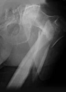
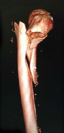
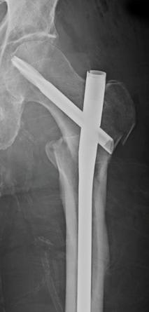
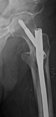
4 TFN-ADVANCED Proximal Femoral Nailing System (TFNA) Clinical Cases Preoperative Postoperative Preoperative Postoperative TFN-ADVANCED Proximal Femoral Nailing System (TFNA) Surgical Technique DePuy Synthes 3

5 AO PRINCIPLES Principles In In 1958, 1958, the the AO AO formulated formulated four four basic basic principles, principles, which which have have become become the the guidelines guidelines for for internal internal fixation fixation. 1, 1,2 2. 4_Priciples_03.pdf :08 Anatomic Anatomic reduction reduction Fracture Fracture reduction reduction and and fixation fixation to to restore restore anatomical anatomical relationships. relationships. 1 2 Stable Stable fixation fixation Fracture Fracture fixation fixation providing providing absolute absolute or relative or relative stability, stability, as required as by the required patient, by the the injury, patient, and the the injury, personality and the personality of the fracture. of the fracture. Early, Early, active mobilization Early Early and and safe safe mobilization and rehabilitation of of the injured part and and the the patient as as a whole. 4 3 Preservation Preservation of of blood blood supply supply Preservation Preservation of of the the blood blood supply supply to to soft soft tissues tissues and and bone bone by by gentle reduction gentle reduction techniques techniques and and careful careful handling. handling. 11. Müller ME, ME, M Allgöwer, M, R Schneider, R, H Willenegger. H. Manual of Internal Fixation. Fixation. 3rd ed. 3rd Berlin, ed. Heidelberg Berlin Heidelberg New York: New Springer York: Springer Rüedi TP, TP, RE RE Buckley, CG Moran. AO Principles of of Fracture Management. 2nd 2nd ed. ed. Stuttgart, New York: Thieme DePuy Synthes TFN-ADVANCED Proximal Femoral Nailing System (TFNA) Surgical Technique

6 Indications, Contraindications, and Precautions USA Indications The TFN-ADVANCED Proximal Femoral Nailing System (TFNA) is intended for treatment of fractures in adults and adolescents (12 21) in which the growth plates have fused. Specifically, the system is indicated for: Stable and unstable pertrochanteric fractures Intertrochanteric fractures Basal neck fractures Combinations of pertrochanteric, intertrochanteric, and basal neck fractures The Long Nail is additionally intended for treatment of fractures in adults and adolescents (12 21) in which the growth plates have fused for the following indications: Subtrochanteric fractures Pertrochanteric fractures associated with shaft fractures Pathologic fractures (including prophylactic use) in both trochanteric and diaphyseal regions Long subtrochanteric fractures Proximal or distal nonunions, malunions and revisions Both the short and long TFNA Systems are additionally indicated for use with cleared, polymethylmethacrylate (PMMA) bone cement that can be delivered through the fenestrated blade or screw via a cannula in skeletally mature adults with risk of cut-out or device instability due to poor bone quality. Contraindications for TFNA System with PMMA bone cement: When used with bone cement: Risk for intra-articular cement leakage. Acute traumatic fractures with good bone quality. Intracapsular hip fractures. In the presence of active or incompletely treated infection at the site where the bone cement is to be applied. TFN-ADVANCED Proximal Femoral Nailing System (TFNA) Surgical Technique DePuy Synthes 7
7 Indications, Contraindications, and Precautions Precautions Use of these devices is not recommended when there is systemic infection, infection localized to the site of the proposed implantation or when the patient has demonstrated allergy or foreign body sensitivity to any of the implant materials. Caution should be taken prior to and during implantation in the presence of tumor(s) at the augmentation site. Physician should consider patient bone quality to ensure it provides adequate fixation to promote healing. Conditions that place excessive stresses on bone and implant such as severe obesity or degenerative diseases, should be considered. The decision whether to use these devices in patients with such conditions must be made by the physician taking into account the risks versus the benefits to the patients. Compromised vascularity in the site of proposed implantation may prevent adequate healing and thus preclude the use of this or any orthopaedic implant. MR information: The TFN-ADVANCED Proximal Femoral Nailing System has not been evaluated for safety and compatibility in the MR environment. They have not been tested for heating, migration, or image artifact in the MR environment. The safety of these devices in the MR environment is unknown. Scanning a patient who has this device may result in patient injury. Canada Indications The TFN-ADVANCED Proximal Femoral Nailing System (TFNA) is intended for treatment of fractures in adults and adolescents (12 21) in which the growth plates have fused. Specifically, the system is indicated for: Stable and unstable pertrochanteric fractures Intertrochanteric fractures Basal neck fractures Combinations of pertrochanteric, intertrochanteric, and basal neck fractures The Long Nail is additionally intended for treatment of fractures in adults and adolescents (12 21) in which the growth plates have fused for the following indications: Subtrochanteric fractures Pertrochanteric fractures associated with shaft fractures Pathologic fractures (including prophylactic use) in both trochanteric and diaphyseal regions Long subtrochanteric fractures Proximal or distal nonunions, malunions and revisions Precautions Use of these devices is not recommended when there is systemic infection, infection localized to the site of the proposed implantation or when the patient has demonstrated allergy or foreign body sensitivity to any of the implant materials. Physician should consider patient bone quality to ensure it provides adequate fixation to promote healing. Conditions that place excessive stresses on bone and implant such as severe obesity or degenerative diseases, should be considered. The decision whether to use these devices in patients with such conditions must be made by the physician taking into account the risks versus the benefits to the patients. Compromised vascularity in the site of proposed implantation may prevent adequate healing and thus preclude the use of this or any orthopaedic implant. MR information: The TFN-ADVANCED Proximal Femoral Nailing System has not been evaluated for safety and compatibility in the MR environment. They have not been tested for heating, migration, or image artifact in the MR environment. The safety of these environment is unknown. Scanning a patient who has this device may result in patient injury. 6 DePuy Synthes TFN-ADVANCED Proximal Femoral Nailing System (TFNA) Surgical Technique


8 TRAUMACEM V+ Augmentation System Indications The TRAUMACEM V+ Injectable Bone Cement is indicated for augmentation of the TFN-ADVANCED Proximal Femoral Nailing System through cannulated implants and instruments for patients with poor bone quality (e.g., osteoporosis). Contraindications Risk for cement leakage outside the intended application site Intracapsular hip fractures PMMA bone cement is contraindicated in the presence of active or incompletely treated infection at the site where the bone cement is to be applied Patients with severe cardiac and/or pulmonary insufficiency Patients with known hypersensitivity or allergy to any of the components of cement (see Composition of Cement) Application to children or to women during pregnancy or lactation Arthroplasty procedures Acute traumatic fractures with good bone quality Canada TRAUMACEM V+ Augmentation System is not approved for sale in Canada. For indications, contraindications, and composition of the TRAUMACEM V+ Injectable Bone Cement - Sterile, the TRAUMACEM V+ Syringe Kit - Sterile, and the TRAUMACEM V+ Injection Cannula for TFNA - Sterile, please consult the corresponding Instructions for Use. TFN-ADVANCED Proximal Femoral Nailing System (TFNA) Surgical Technique DePuy Synthes 7


. 2.")

9 Preparation 1. Position patient Position the patient in the lateral decubitus or supine position on a fracture or radiolucent table. Position the image intensifier to enable visualization of the proximal femur in both the AP and lateral planes. For unimpeded access to the medullary canal, move the upper part of the body approximately to the contralateral side out of the operative field (or adduct the affected leg by ). 2. Fracture reduction Perform closed reduction manually by axial traction under image intensifier control. The use of the large distractor (refer to instructions for use) may be appropriate in certain circumstances. If reduction can not be achieved in a closed approach, open reduction may be considered. 7 DePuy Synthes TFN-ADVANCED Proximal Femoral Nailing System (TFNA) Surgical Technique


10 Preparation 3. Determine femoral neck angle Instruments Radiographic Ruler mm Guide Wire 400 mm The three oblique holes at the proximal end of the radiographic ruler are used to determine the femoral neck angle. Select a 3.2 mm guide wire and insert the guide wire in line with one of the grooves marked 125, 130, or 135. Position the ruler over the proximal femur and take an AP image. Select the angle that most closely matches the angle of the femoral neck and position the radiographic ruler such that the guide wire is aimed centrally in the femoral head. Mark the position of the ruler on the skin to assist the next steps. Mark the skin at the proximal outline of the ruler. Notes: The proximal end of the ruler represents the proximal nail end after insertion. The slot on the proximal end refers to the path of the guide wire, used for opening of the femur. All AP images of the proximal femur are made with correction for the anteversion, either by internally rotating the femur or by adjustment of the image intensifier. TFN-ADVANCED Proximal Femoral Nailing System (TFNA) Surgical Technique DePuy Synthes 3


11 Preparation 4. Determine nail length Instrument Radiographic Ruler Move the image intensifier to the distal femur, place the proximal end of the radiographic ruler at the skin mark, and take an AP image of the distal femur. Verify fracture reduction. Read nail length directly from the ruler image, selecting the measurement that places the distal end of the nail at, or just proximal to, the physeal scar, or the chosen insertion depth. Alternative: Nail length may also be determined by using a reaming rod, see page 15 for technique. 10 DePuy Synthes TFN-ADVANCED Proximal Femoral Nailing System (TFNA) Surgical Technique


12 Preparation 5. Determine nail diameter Instrument Radiographic Ruler To determine nail diameter, position the image intensifier for an AP view of the femur at the level of the isthmus. Hold the radiographic ruler perpendicular to the femur and position the diameter windows over the isthmus. Read the estimated diameter measurement on the circular indicator that fills the canal. Notes: The distance of the radiographic ruler from the bone affects the diameter measurement. Estimate the width as follows: Distance between the radiographic ruler and bone a. 25 mm = 1 mm larger reading b. 50 mm = 2 mm larger reading c. 100 mm = 3 mm larger reading If the reamed technique is used, the diameter of the largest medullary reamer applied must be 0.5 mm to 1.5 mm larger than the nail diameter. TFN-ADVANCED Proximal Femoral Nailing System (TFNA) Surgical Technique DePuy Synthes 11


13 Open Proximal Femur 1. Identify nail entry point Make a longitudinal incision proximal to the greater trochanter. Carry the dissection down to the gluteus medius fascia longitudinally in the direction of the wound. Separate the underlying muscle fibers and palpate the tip of the greater trochanter. 5 In the AP view, the nail insertion point is on the tip or slightly lateral to the tip of the greater trochanter, in the curved extension of the medullary cavity. This represents a point, 5 lateral of the femoral shaft axis, measured from a point just below the lesser trochanter, as the ML angle of the nail is 5. In the lateral view, the entry point for the nail is centered in the greater trochanter and in line with the medullary canal. 12 DePuy Synthes TFN-ADVANCED Proximal Femoral Nailing System (TFNA) Surgical Technique


14 Open Proximal Femur 2. Insert guide wire Instruments Multi Hole Wire Guide mm Protection Sleeve mm Guide Wire 400 mm Universal Chuck with T-Handle Alternative instruments Percutaneous Multi Hole Wire Guide mm Percutaneous Protection Sleeve mm Guide Wire 475 mm Universal Chuck with T-Handle Position the 16 mm protection sleeve and the multi hole wire guide assembly at the insertion point. Insert the guide wire through the wire guide. Confirm guide wire placement in both the AP and lateral planes. Insert to a depth of approximately 15 cm. Remove the wire guide. Alternatively the guide wire can be inserted without the protection sleeve and multiple wire guide. The protection sleeve and wire guide can then be passed over the guide wire. If the first guide wire is inserted in an incorrect position, a second guide wire can be inserted through one of the additional holes in the multi hole wire guide at either 4 mm or 6 mm from the central hole. Once the guide wire is in the desired entry point, remove the first guide wire. TFN-ADVANCED Proximal Femoral Nailing System (TFNA) Surgical Technique DePuy Synthes 13


15 Open Proximal Femur Alternative technique Instrument mm Cannulated Curved Awl or mm Cannulated Straight Awl Instead of using the guide wire, the 8 mm awl can be used to create a path for the reaming rod. After initial opening with the awl, insert the 950 mm reaming rod through the cannulation. 3. Open canal Instruments mm Protection Sleeve mm Cannulated Flexible Drill Bit or mm Cannulated Drill Bit Alternative instruments mm Percutaneous Protection Sleeve mm Cannulated Percutaneous Flexible Drill Bit or mm Cannulated Percutaneous Drill Bit Guide the 16 mm cannulated drill bit over the guide wire through the 16 mm protection sleeve to the bone and drill to the stop. Remove and dispose of the guide wire. Do not reuse. 14 DePuy Synthes TFN-ADVANCED Proximal Femoral Nailing System (TFNA) Surgical Technique
 03.037.104(S) 16 mm Cannulated Hollow Drill Bit 16 mm Cann Percutaneous Hollow Drill Bit Ensure the centering mechanism is in the correct position prior to using the hollow drill bit.")

16 Open Proximal Femur 3b. Optional technique: Open canal Optional instruments (S) (S) 16 mm Cannulated Hollow Drill Bit 16 mm Cann Percutaneous Hollow Drill Bit Ensure the centering mechanism is in the correct position prior to using the hollow drill bit. The centering mechanism should be pushed all the way down toward the cutting end of the hollow drill bit as depicted in the image. Non-locked position Guide the 16 mm cannulated hollow drill bit over the guide wire through the 16 mm protection sleeve to the bone and drill to the stop. Remove and dispose of the guide wire. Do not reuse. Note: In hard bone after drilling with the hollow drill bit it may be necessary to repeat the opening process with the flexible drill bit. Correct position for drilling Precaution: Monitor the drill depth under fluoroscopy throughout the procedure. TFN-ADVANCED Proximal Femoral Nailing System (TFNA) Surgical Technique DePuy Synthes 17


17 Open Proximal Femur 4. Option: Ream medullary canal If necessary, enlarge the femoral canal to the desired diameter using the medullary reamer and the corresponding technique guide. Use image intensification to confirm fracture reduction. Insert the reaming rod into the medullary canal to the desired insertion depth. The tip must be correctly positioned in the medullary canal since it determines the final distal position of the nail. Reaming Starting with the 8.5 mm diameter reaming head, ream to a diameter of 0.5 mm to 1.5 mm greater than the nail diameter. Ream in 0.5 mm increments and advance the reamer with steady, moderate pressure. Do not force the reamer. Partially retract the reamer repeatedly to clear debris from the medullary canal. Option: Reamer protection tube Instruments mm Protection Sleeve Reamer Protection Tube Trocar for Protection Tube The reamer protection tube can be used to help protect the proximal metaphysis during reaming. Assemble the reamer protection tube, trocar and protection sleeve together. Then take the reamer protection tube assembly and insert it over the reaming rod, sliding the trocar and reamer protection tube into the bone. Remove the inner trocar from the assembly and pass the reamer over the reaming rod and through the protection tube. Then ream per the technique described above. When removing the reamer head through the reamer protection tube be sure to align the angle of the reamer shaft to the protection tube. This will help ensure the reamer head will not get caught on the tube upon removal. Note: The reamer protection tube can only be used with reamer heads up to 13.5 mm. Therefore it can only be used for nails up to 12 mm. Use the Flexible Reamer Set, Long if reaming down to the distal femur is required. 16 DePuy Synthes TFN-ADVANCED Proximal Femoral Nailing System (TFNA) Surgical Technique


18 Open Proximal Femur Option: Determine nail length over reaming rod Instruments Depth Gauge for Trochanteric Nailing System Depth Gauge Extension Tube Nail length can be determined over a 950 mm reaming rod. Confirm reaming rod insertion depth under image intensification. Insert the reaming rod to hold fracture reduction. Pass the reaming rod measuring device over the reaming rod and down to the bone. Read nail length directly from the measuring device. If a 1150 mm reaming rod is used,the nail length measurement should be read off the etched line on the reaming rod. TFN-ADVANCED Proximal Femoral Nailing System (TFNA) Surgical Technique DePuy Synthes 17


. Do not attach the aiming arm to the handle yet.")
19 Insert Nail 1. Assemble insertion instruments Instruments Cannulated Connecting Screw Complete Radiolucent Insertion Handle or Hybrid Insertion Handle or Percutaneous Radiolucent Insertion Handle T-Handle Ball Hex Screwdriver 8 mm mm Hex Flexible Screwdriver Assemble the ball hexagonal screwdriver to the connecting screw by inserting the tip of the screwdriver until it clicks into the recess of the connecting screw. Match the geometry of the handle to the nail and connect the nail to the insertion handle. The nail will click-in and self-retain. Pass the connecting screw through the insertion handle and securely tighten with the ball hexagonal screwdriver. Remove the hexagonal screwdriver. To verify the appropriate position of the locking mechanism for the screw, pass the 5.0 mm flexible screwdriver through the cannulated connecting screw and turn counter clockwise until its stops. Precautions: Ensure that the connection between the nail and the insertion handle is tight (retighten if necessary). Do not attach the aiming arm to the handle yet. If a 235 mm or longer nail is selected, reconfirm that the correct nail (right or left) is assembled. 17 DePuy Synthes TFN-ADVANCED Proximal Femoral Nailing System (TFNA) Surgical Technique

 Orient the insertion handle laterally, taking into consideration the anteversion of the femoral head and neck.")

20 Insert Nail 2. Insert nail Instrument Complete Radiolucent Insertion Handle or Hybrid Insertion Handle or Percutaneous Radiolucent Insertion Handle Short nails (170 mm, 200 mm, and 235 mm) Orient the insertion handle laterally, taking into consideration the anteversion of the femoral head and neck. Manually insert the nail into the femoral opening. When using a reaming rod, pass the cannulated nail over the reaming rod and into the femoral opening. Short nails. Under image intensification, verify fracture reduction and insert the nail as far as possible by hand. Use the insertion assembly to manipulate the nail across the fracture. When inserting a short nail (170 mm, 200 mm, and 235 mm), no hammer blows should be required. Long nails (260 mm to 480 mm) Orient the insertion handle anteriorly until the nail reaches the isthmus. Manually insert the nail into the femoral opening. When using a reaming rod, pass the cannulated nail over the reaming rod and into the femoral opening. As the nail is advanced, rotate the handle so it is positioned laterally for final seating. Under image intensification, verify fracture reduction and insert the nail as far as possible by hand. Use the insertion assembly to manipulate the nail across the fracture. Insertion can be aided by light hammer blows on the driving cap, as described in the step below. If a reaming rod has been used, it should be removed once the nail has crossed the fracture site. Long nails. TFN-ADVANCED Proximal Femoral Nailing System (TFNA) Surgical Technique DePuy Synthes 13


21 Insert Nail 3. Insert nail with hammer (optional) Instruments Spiral Combination Hammer 500 Grams Driving Cap/Threaded Combination Wrench 11 mm/blade Screw Threaded Hammer Guide Connector Hammer Guide To use a hammer, insert the threaded hammer guide connector into the anterior side of the insertion handle. Then screw the driving cap through the insertion handle into the hammer guide connector and tighten with combination wrench. When using the hybrid insertion handle, the threaded hammer guide connector is not used and the driving cap is inserted directly into the hybrid insertion handle. While applying light blows, monitor the tip of the nail using image intensification. Verify that there is no evidence of impingement distally. Remove the driving cap and hammer guide connector once the nail has been seated. Note: Using light blows, the hammer can also be used with the threaded hammer guide to back slap the nail if the nail has been slightly over inserted. Precaution: Confirm that the nail is tightly connected to the insertion handle, as hammering may loosen the connection. 20 DePuy Synthes TFN-ADVANCED Proximal Femoral Nailing System (TFNA) Surgical Technique


22 Proximal Locking 1. Choose aiming arm Instrument Deg Aiming Arm or * 125 Deg Aiming Arm or * 135 Deg Aiming Arm Ensure that the nail is tightly connected to the insertion handle. Retighten if necessary. Choose the aiming arm that matches the angle of the nail inserted and securely attach to the insertion handle using the thumb screw. 2. Verify nail insertion depth Instrument mm Guide Wire 400 mm Verify nail insertion depth and position for the helical blade/screw. Place a guide wire on the yellow marking of the aiming arm and radiographically check the guide wire position in AP. *Also available. TFN-ADVANCED Proximal Femoral Nailing System (TFNA) Surgical Technique DePuy Synthes 21


23 Proximal Locking Alternative technique: Position guide wire with guide wire aiming device Instruments Guide Wire Aiming Device F/TFN For Ant Posterior Orientation Connecting Screw F/Guide Wire Aiming Device F/TFN * Guide Wire Aiming Device Offset Block Attach the guide wire aiming device for AP orientation into the three holes on the anterior side of the aiming arm and lock in place using the connecting screw. Option: The guide wire aiming device offset block can be added between the aiming arm and the guide wire aiming device to obtain an additional 10 cm of soft tissue clearance. Position the image intensifier for an AP image. Rotate the image intensifier until any two orientation lines are parallel to the hole for the helical blade/screw. The midline (line between the two orientation lines) represents the guide wire trajectory. Note: The outer lines can be used to determine the center of the femoral head. *Also available. 22 DePuy Synthes TFN-ADVANCED Proximal Femoral Nailing System (TFNA) Surgical Technique

.")


24 Proximal Locking 3. Verify nail anteversion Instrument mm Guide Wire 400 mm Position the image intensifier in the true lateral view (alignment of the axis of the femoral neck parallel to the axis of the femoral shaft). Adjust nail rotation until the two radiographic lines on the insertion handle are parallel to the nail. Option: A 3.2 mm guide wire can be inserted in the corresponding hole in the insertion handle to predict the location of the guide wire and helical blade/screw. Note: The guide lines are located in the handle portion of the insertion handle and are made from a radio-opaque material. The lines provide a visual reference for guide wire insertion verifying nail anteversion. TFN-ADVANCED Proximal Femoral Nailing System (TFNA) Surgical Technique DePuy Synthes 23


25 Proximal Locking 4. Insert guide sleeve Instruments Buttress/Compression Nut Blade/Screw Guide Sleeve mm Wire Guide Sleeve mm Trocar Long Scalpel Handle To make an incision to accommodate the path of the sleeve assembly, insert the scalpel handle with scalpel blade attached through the corresponding hole of the aiming arm. Ensure that the incision and dissection of the fascia is in line with the path of the guide sleeve. Thread the buttress/compression nut onto the blade/ screw guide sleeve, to the black marking on the blade/screw guide sleeve. Insert the wire guide sleeve and trocar into the blade/screw guide sleeve. Place the yellow marked guide sleeve assembly through the aiming arm and through the soft tissue to the bone. Slightly rotating the wire guide sleeve while pushing the guide sleeve assembly through the soft tissue may help facilitate insertion. The buttress/compression nut will snap into the aiming arm. 24 DePuy Synthes TFN-ADVANCED Proximal Femoral Nailing System (TFNA) Surgical Technique


26 Proximal Locking Turn the buttress/compression nut counterclockwise to advance the guide sleeve to the bone. Take an AP image to confirm that the tooth on the guide sleeve is just touching the lateral cortex. Precaution: The distal tooth of the guide sleeve should rest on the lateral cortex. Do not over tighten on the cortex as this may affect the accuracy of the aiming assembly. Using a light hammer blow, hit the trocar into the bone to create an indentation in the bone which will help prevent the guide wire from skiving off of the bone in the next step. Reconfirm fracture reduction using image intensification. TFN-ADVANCED Proximal Femoral Nailing System (TFNA) Surgical Technique DePuy Synthes 27


27 Proximal Locking 5. Insert guide wire for blade or screw Instruments mm Trocar mm Guide Wire 400 mm Remove the 3.2 mm trocar and pass a new 3.2 mm guide wire through the wire guide to the bone. Advance the guide wire, under power, into the femoral head, stopping approximately 10 mm below the joint level. The guide wire should be centered in the femoral head and neck in both the AP and lateral planes. The tip of the guide wire is positioned where the tip of the head element will be when the head element is properly inserted. Confirm guide wire placement, in both planes, using the image intensifier. Precautions: If the nail must be repositioned to improve guide wire placement, remove the sleeve assembly and adjust with the insertion handle. Make a new incision for insertion of the guide sleeve. Do not pull on the guide sleeve or power tool to make this adjustment as this could affect the accuracy of the aiming. Do not reuse guide wires as they may bend during initial use. If the guide wire is deformed during insertion use a new guide wire and discard deformed guide wire. 10 mm Note: When inserting the guide wire in patients with larger anatomies, you may need to stop during insertion of the wire and remove the wire guide sleeve and continue advancing the wire to the desired depth. This is most likely to occur in anatomies requiring blade/screw lengths of 120 mm or larger. 26 DePuy Synthes TFN-ADVANCED Proximal Femoral Nailing System (TFNA) Surgical Technique

28 Proximal Locking Optional technique: Rotational control of femoral head Instruments mm Guide Wire 400 mm mm/3.2 mm Drill Guide 198 mm If the fracture line is perpendicular to the axis of the head element or if rotational control of the femoral head during head element insertion is a concern, the following technique may be utilized. Pass the 5.6 mm/3.2 mm drill guide through the corresponding anterior or posterior hole on the aiming arm. Make a stab incision and pass the guide to the bone. Advance a 3.2 mm guide wire into the femoral head. Monitor passage with the image intensifier. Repeat to place a second guide wire if necessary. The guide wires will converge toward the tip of the head element, in the lateral view, but will not touch it. The guide wires should be used for provisional fixation only and removed once the head element has been inserted. TFN-ADVANCED Proximal Femoral Nailing System (TFNA) Surgical Technique DePuy Synthes 27


29 Proximal Locking 6. Measure for length of blade or screw Instrument Helical Blade/Screw Measuring Device To measure for blade or screw length, pass the helical blade/screw measuring device over the guide wire to the back of the guide sleeve. Blade or screw length is read directly from the measuring device. No calculations are required. Note: The measurement is calibrated from the tip of the guide wire to the tip of the tooth on the guide sleeve. 27 DePuy Synthes TFN-ADVANCED Proximal Femoral Nailing System (TFNA) Surgical Technique


30 Proximal Locking 7. Drill for helical blade or screw Instruments Blade/Screw Guide Sleeve mm Cannulated Tapered Drill Bit Remove the wire guide sleeve from the blade/screw guide sleeve. Place the 10 mm cannulated tapered drill bit in a power tool. Pass the drill bit over the guide wire, through the blade/screw guide sleeve, and advance under power. Drill to the stop. This will open the lateral cortex. Note: If the guide wire deflected as it passed into the femoral head/neck, it may be removed before drilling and blade/screw insertion. If the guide wire falls out or comes out when the drill bit is removed, it may be left out for blade/screw insertion. Care should be taken to ensure the orientation of the insertion handle and aiming arm is not altered. TFN-ADVANCED Proximal Femoral Nailing System (TFNA) Surgical Technique DePuy Synthes 23


31 Proximal Locking Option: Drilling for dense bone or when using a TFNA Screw Instruments mm/9 mm Cannulated Stepped Drill Bit Drill Stop for Reaming Rod Push Rod with Ball Handle For dense bone or when using a TFNA Screw, the 6 mm/9 mm cannulated stepped drill bit should be used to prepare a path for the full length of the shaft of the head element. The stepped drill bit should be used only after the cortex has been opened using the 10 mm tapered drill bit. Pass the drill stop over the back end of the stepped drill bit and check the drill stop for wear per the instructions on page 50. Adjust the setting to the measured blade or screw length. Pass the drill bit over the guide wire, through the guide sleeve and advance under power. Drill to the stop. Use the rod pusher through the power tool to hold the guide wire in place while removing the 6 mm/9 mm cannulated stepped drill. Notes Clean the flutes if high resistance is felt. Drill always stops 5 mm short of the wire tip. Rod pusher can be used to hold the guide wire in the bone when the drill is retracted. Precaution: Monitor the drill depth under fluoroscopy throughout the procedure. 30 DePuy Synthes TFN-ADVANCED Proximal Femoral Nailing System (TFNA) Surgical Technique


32 Proximal Locking Option A: Blade Insertion 8a. Assemble helical blade Instruments Helical Blade Inserter Helical Blade/Screw Coupling Screw Insert the cannulated helical blade coupling screw and thread in until fully captured in the helical blade inserter. The coupling screw will remain attached to the inserter. Select the appropriate length helical blade as measured. Align the back end of the helical blade with the inserter. Further thread the coupling screw into the helical blade and finger tighten the assembly. TFN-ADVANCED Proximal Femoral Nailing System (TFNA) Surgical Technique DePuy Synthes 31


33 Proximal Locking Option A: Blade Insertion 9a. Insert helical blade Instrument Spiral Combination Hammer 500 Grams Pass the helical blade insertion assembly through the helical blade/screw guide sleeve and align the red line on the inserter shaft with the red line on the guide sleeve. Advance the blade as far as possible by hand. Use light hammer blows on the back of the coupling screw until the blade inserter comes to a stop at the back of the blade/screw guide sleeve. In the final position the yellow line of the helical blade/screw guide sleeve and the helical blade inserter are in alignment. The helical blade MUST be fully inserted. Precautions: Image intensifier should be used during blade insertion to monitor positioning. Assure that the guide wire is in place while inserting the helical blade to prevent the cannulation from clogging, impeding an optional augmentation procedure. Option: Intraoperative exchange of the blade Instrument Driving Cap/Threaded To intraoperatively exchange the blade, attach the driving cap/threaded to the back of the coupling screw. Use the hammer to back slap if needed. 32 DePuy Synthes TFN-ADVANCED Proximal Femoral Nailing System (TFNA) Surgical Technique


34 Proximal Locking Option B: Screw insertion 8b. Tap for screw (optional) Instrument Tap for Screw The tap may be used to prepare a pathway for the screw. Note: Only use the tap in dense bone. Pass the tap over the guide wire, through the guide sleeve and through the nail. Advance the tap manually by turning clockwise until the measurement graduations on the shaft of the tap reach the measurement selected for the screw. Precaution: There is no stop on the tap so monitoring insertion via the following methods is recommended: Monitor the depth under fluoroscopy. Monitor the respective graduations of the instrument shaft in relation to the guide sleeve. Remove the tap by turning counterclockwise. 9b. Assemble screw Instruments Screw Inserter Helical Blade/Screw Coupling Screw Insert the cannulated coupling screw and thread in until fully captured in the screw inserter. The coupling screw will remain attached to the inserter. Select the appropriate length screw as measured. Align the back end of the screw with the inserter. Further thread the coupling screw into the screw and finger tighten the assembly. TFN-ADVANCED Proximal Femoral Nailing System (TFNA) Surgical Technique DePuy Synthes 33


35 Proximal Locking Option B: Screw Insertion 10b. Insert screw Starting notes: The screw advances in 1.75 mm increments by turning the handle 180 (or 3.5 mm by turning 360 ). When adjusting for final positioning, always rotate the handle clockwise, further engaging the screw in the bone. Do not rotate counterclockwise, as this will leave a gap between the screw and the bone. The screw can be over inserted a maximum of 1 (one) full turn. The etched image of the screw on the inserter shaft indicates the orientation of the lateral oblique cut of the screw. Pass the screw insertion assembly over the guide wire, through the guide sleeve and through the nail. Advance the screw by turning the inserter clockwise until the line on the inserter meets the flange surface of the guide sleeve. At this depth the screw tip will be positioned at the tip of the guide wire. Assure that the inserter handle is aligned to the aiming arm. This is essential for proper engagement of the locking mechanism. Precautions: Image intensifier should be used during screw insertion to monitor positioning. Assure that the guide wire is in place while inserting the screw to prevent the cannulation from clogging, impeding an optional augmentation procedure. 34 DePuy Synthes TFN-ADVANCED Proximal Femoral Nailing System (TFNA) Surgical Technique


36 Proximal Locking 11. Rotational locking Engaging locking mechanism against rotation Instrument mm Hex Flexible Screwdriver The preassembled locking mechanism in the nail must be advanced to control the rotation of the blade or screw. Pass the 5 mm flexible screwdriver through the cannulated connecting screw and insertion handle until it is seated in the hexagonal recess of the locking mechanism. Turn clockwise to advance the locking mechanism. Advance the screwdriver down until it stops completely, then back the screwdriver off by turning counterclockwise 1/2 turn (180 degrees). The blade or screw is now locked in rotation but can still slide. Precaution: If the locking mechanism is not turned back 1/2 turn after initial tightening as described above, controlled collapse and compression of the fracture may not occur. *Also available. TFN-ADVANCED Proximal Femoral Nailing System (TFNA) Surgical Technique DePuy Synthes 37


37 Proximal Locking Option: Interfragmentary Compression Option A: Blade compression Instrument mm Pin Wrench 120 mm Once the blade has been locked in rotation, interfragmentary compression can be obtained by turning the buttress/compression nut clockwise by hand. For additional leverage, use the 4.5 mm pin wrench. Precaution: Caution should be taken when using the buttress/compression nut with the pin wrench to avoid over compression which could potentially cause the blade or screw to lose purchase in the bone, especially in patients with poor bone quality. Option B: Screw compression Instruments Compression Nut for Screw Inserter mm Pin Wrench 120 mm Once the screw has been locked in rotation, interfragmentary compression can be obtained by mounting the compression nut onto the screw inserter, advancing it until it abuts the guide sleeve, and then turning the buttress/compression nut clockwise by hand or with the assistance of the 4.5 mm pin wrench. Precaution: Caution should be taken when using the buttress/compression nut with the pin wrench to avoid over compression which could potentially cause the blade or screw to lose purchase in the bone, especially in patients with poor bone quality. 36 DePuy Synthes TFN-ADVANCED Proximal Femoral Nailing System (TFNA) Surgical Technique


38 Proximal Locking Option: Interfragmentary Compression Option: Static locking Engage locking mechanism to prevent sliding Instruments mm Hex Screwdriver Shaft* Torque Limiting Attachment 6Nm** T-Handle/Cannulated with Quick Coupling Alternative instrument Nm Torque Limiting Blue Handle with 6 mm Hex Coupling Once compression has been achieved, the blade or screw can be statically locked to prevent sliding of the blade/ screw through the nail. Assemble the 6Nm torque limiting attachment into the T-Handle and then the 5 mm hex shaft into the torque limiting attachment to complete the static locking screwdriver assembly. Pass the static locking screwdriver assembly through the cannulated connecting screw and insertion handle until it is seated in the hexagonal recess of the lock drive and turn clockwise to advance. After one click, the optimal torque is reached and the blade or screw is statically locked. Note: The torque limiting attachment ensures that the correct torque is achieved, thus ensuring sliding is prevented. *Also available. ** Recalibration of the torque limiter: DePuy Synthes Trauma recommends annual servicing and inspection by the original manufacturer. The torque limiter has to be sent to your DePuy Synthes Trauma repair center annually for calibration. The user accepts the responsibility for this annual calibration. TFN-ADVANCED Proximal Femoral Nailing System (TFNA) Surgical Technique DePuy Synthes 37


39 Proximal Locking 12. Remove proximal locking instruments Disconnect the coupling screw from the blade or screw and remove the inserter/coupling screw assembly. If the connecting screw cannot be loosened by hand, use the 5 mm flexible hexagonal screwdriver to loosen the connection. If no augmentation is planned, remove the guide sleeve from the aiming arm by depressing the locking device on the aiming arm and pulling out the guide sleeve. Remove the guide wire. Continue with distal locking. If augmentation is planned, remove the helical blade impactor/screw inserter and leave the guide sleeve in place to facilitate augmentation. 37 DePuy Synthes TFN-ADVANCED Proximal Femoral Nailing System (TFNA) Surgical Technique
40 Augmentation General notes It is recommended to use 3 ml of cement for augmentation. This amount of cement minimizes the risk of avascular necrosis and is sufficient to achieve the desired stability. The injected amount must not exceed 6 ml of cement. Aimed placement of cement is around the helical part of the blade/screw. The exact amount of cement depends on surgeon discretion informed by patient anatomy. It is recommended to control injection under fluoroscopy in order to maintain a minimum distance of 6 mm between the bone cement and the joint surface. Filling of the cavity lateral to the helical part of the blade/screw is not necessary. The fenestrated TFNA Screws and TFNA Helical Blades may be used with or without augmentation. The non-fenestrated TFNA Screws and TFNA Helical Blades may only be used without augmentation. Product Code: S Description: TRAUMACEM V+ Injectable Bone Cement, sterile TRAUMACEM V+ Injectable Bone Cement is a cleared PMMA bone cement with the required parameters to be utilized in this application. The working time for TRAUMACEM V+ Injectable Bone Cement at room temperature (20 C) is approximately 27 minutes. At body temperature (37 C) the setting time is 15 minutes. Mobilizing/repositioning the patient before 15 minutes after the last injection should therefore be avoided. Important Information for Physician The physician should, by specific training and experience, be thoroughly familiar with the properties, handling characteristics, and application of bone cements. Because the handling and curing characteristics of this bone cement vary with temperature, humidity, and mixing technique, they are best determined by the surgeon s actual experience. For this reason, the physician is strongly recommended to carry out a trial run of the entire mixing, handling, and setting process prior to performing a surgical procedure with TRAUMACEM V+ Injectable Bone Cement. Note: Refer to bone cement instructions for use. TFN-ADVANCED Proximal Femoral Nailing System (TFNA) Surgical Technique DePuy Synthes 33

, while holding the handle of the")

41 Augmentation 1. Adjust sleeve of side-opening cannula Instrument S TRAUMACEM V+ Injection Cannula, for TFNA System, sterile Adjust the sleeve of the side-opening cannula to the selected head element length. Length adjustments are made by turning the sleeve (2), while holding the handle of the side-opening cannula (1). One clockwise turn of the sleeve relates to 5 mm lateral axial movement of the side-opening cannula. 40 DePuy Synthes TFN-ADVANCED Proximal Femoral Nailing System (TFNA) Surgical Technique


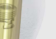
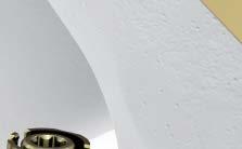
42 Augmentation 2. Check for possible cement leakage into joint Instrument S TRAUMACEM V+ Injection Cannula, for TFNA System, sterile Other materials 1 2 Syringes with Luer lock Radiographic contrast agent Saline solution Attach the syringe with luer lock to the side-opening cannula and prefill the side-opening cannula with radiographic contrast agent. Insert the side-opening cannula through the guide sleeve into the helical blade/screw until the stop. Confirm that the selected length on the side-opening cannula corresponds with the length of the helical blade/ screw and verify under image intensification that the side opening cannula is fully inserted. At the correct position the tip of the sleeve has disappeared in the lateral end of the helical blade/screw. Monitor the correct position of the sleeve throughout the procedure. Wrong tip of the sleeve visible. Correct tip has disappeared in the screw/blade. TFN-ADVANCED Proximal Femoral Nailing System (TFNA) Surgical Technique DePuy Synthes 41

43 Augmentation Inject radiographic contrast agent into the femoral head and monitor the flow under image intensification. Remove the side-opening cannula. Wash the radiographic contrast agent out of the cannula using a saline solution and another syringe, attached to the side-opening cannula. Warning: Do not augment if radiographic contrast agent leaks into the joint and proceed with distal locking. Radiographic contrast agent leakage into the joint indicates significant risk for intra-articular PMMA bone cement leakage and therefore augmentation is contraindicated. No leakage into joint. Leakage into joint, do not augment. Precautions: Do not use radiographic contrast agents that are contraindicated for this application. Consult the manufacturer s directions on indications, contraindications, use, precautions, warnings and side effects of the radiographic contrast agent. 44 DePuy Synthes TFN-ADVANCED Proximal Femoral Nailing System (TFNA) Surgical Technique


. Remove and dispose the mixing device sterilization lid.")


44 Augmentation 3. Prepare cement Instrument S TRAUMACEM V+ Injectable Bone Cement, sterile Hold the TRAUMACEM V+ Injectable Bone Cement upright and gently slap with the finger tip at the top of the mixing device in order to ensure no cement powder sticks to the cartridge and sterilization lid. Pull the handle until it is fully retracted. Note: Make sure to always handle the mixing device by gripping the blue part located directly below the transparent cartridge. If the transparent part is used as gripping surface, the excess body heat provided by the user s hand might result in a shorter working time than intended. Open the glass ampoule by breaking the bottle neck with the plastic cap (1). Remove and dispose the mixing device sterilization lid. Pour all monomer from the glass ampoule into the cement powder (2) and close the mixing device tightly using the enclosed transferring lid. 1 Fully compressed stop Note: Always use the full amounts of monomer liquid and polymer powder provided in the kit, respectively, when mixing TRAUMACEM V+ Injectable Bone Cement. Otherwise, the behavior of the TRAUMACEM V+ Injectable Bone Cement can no longer be guaranteed. Using only one of the components is not permitted. 3 2 Fully extended stop Mix the TRAUMACEM V+ Injectable Bone Cement by moving the blue handle back and forth from stop to stop approximately 20 times (1). Perform the first mixing strokes slowly with oscillating-rotating movements (2). After mixing fully retract the handle (3). Note: Ensure thorough mixing. TFN-ADVANCED Proximal Femoral Nailing System (TFNA) Surgical Technique DePuy Synthes 43

 to the mixer.")


45 Augmentation 4. Fill injection syringes Instrument S TRAUMACEM V+ Syringe Kit, 4 x 1 ml, 2 x 2 ml, sterile 1 Once the cement has been mixed using the TRAUMACEM V+ Injectable Bone Cement remove the small, transparent mixer lid (1). Connect the stop-cock (the side without the funnel) to the mixer. Ensure a tight fit between the mixer and the stop-cock (2). Note: The application of excessive torque will break the stop-cock. First remove the air from the system. With the valve open, gently turn the handle of the cement mixer clockwise. The mixer piston will advance in the translucent cartridge and a steady flow of cement will move into the stop-cock. As soon as the cement is visible in the stopcock, close the valve (3). 2 3 Note: Do not push to transfer cement. 44 DePuy Synthes TFN-ADVANCED Proximal Femoral Nailing System (TFNA) Surgical Technique
.")


46 Augmentation Attach a 2 ml (white) syringe to the one way stop-cock (funnel side). Open the one way stop-cock (the off sign facing away from the syringe). Gently turn the handle of the cement mixer clockwise to advance the piston. As soon as the syringe is filled, close the stop-cock again, by turning the off sign towards the mixer. Disconnect the full syringe and attach the next syringe to be filled. Avoid spillage of cement into the funnel during the transfer process and remove excess cement to avoid accidental pollution of the protection sleeve, blade or screw. Continue to fill all the 1 ml (blue) and 2 ml (white) syringes in the same manner. Always fill all syringes. TFN-ADVANCED Proximal Femoral Nailing System (TFNA) Surgical Technique DePuy Synthes 47

47 Augmentation 5. Prefill the side-opening cannula with cement Instrument S TRAUMACEM V+ Injection Cannula, for TFNA System, sterile Attach a cement filled 2 ml syringe to the side-opening cannula. Prefill the side-opening cannula with the 2 ml of cement from the syringe. Attach another filled 2 ml syringe and fill the side-opening cannula until the cement is coming out of the side opening, representing 4 ml of cement filled into the cannula. Remove and discard the syringes. Attach a filled 1 ml syringe to the side-opening cannula in preparation of the augmentation. In case of cement leakage from the side opening, remove the excess cement in order to avoid accidental pollution of the protection sleeve or blade/screw. Note: 1 ml syringes must be used to inject cement. The 2 ml syringes are not suited to augment the blade/screw. Upon injection of 3 1 ml syringes, approximately 3 ml of cement has been delivered out of the head element. 46 DePuy Synthes TFN-ADVANCED Proximal Femoral Nailing System (TFNA) Surgical Technique


48 Augmentation 6. Insert side-opening cannula Confirm that the selected length on the side-opening cannula corresponds with the length of the helical blade/screw. Insert the side-opening cannula through the guide sleeve into the blade/screw until the stop. Verify under image intensification that the side-opening cannula is fully inserted. TFN-ADVANCED Proximal Femoral Nailing System (TFNA) Surgical Technique DePuy Synthes 47


49 Augmentation 7. Augmentation with cement Instrument S TRAUMACEM V+ Injection Cannula, for TFNA System, sterile Injection of cement into the femoral head is performed using 1 ml syringes. Slowly inject the cement using 1 ml syringes. Optimize the filling by rotating the handle to inject cement around the blade/screw. It is recommended that the surgeon maintain a minimum distance of 6 mm between the boundary of the cement and the joint surface. If noted under fluoroscopy that the cement is traveling towards the joint surface, move the cannula laterally by rotating the sleeve 1 clockwise turn. Warning: The 6-mm minimum distance is recommended to reduce the risk of thermal injury to the adjacent cartilage tissue. Visualization of cement during injection must be guaranteed. Continuously monitor the cement flow under image intensification. Precautions: Do not advance the cannula more than 5 mm over the selected head element length. This would result in injection of cement in front of the head element tip where no additional stability is achieved and the risk of penetration and cement leakage is increased. In the event that there is danger of cement leakage into the joint or fracture gap, stop injection immediately. Correct distance between cement boundary and the joint surface. Note: The arrow on the handle indicates the position of the side-opening window of the cannula. 47 DePuy Synthes TFN-ADVANCED Proximal Femoral Nailing System (TFNA) Surgical Technique


50 Augmentation Options: Injection of cement can be continued using the plunger when the viscosity is increasing or the cement in the cavity of the side-opening cannula is necessary for augmentation. Approximately 3 ml of cement contained in the side-opening cannula can be injected with the plunger. Remove the 1 ml syringe and insert the plunger. Continue the injection using the plunger and optimize the filling by rotating the handle. Warnings: If the extravasated cement conforms to the architecture of the hip joint it may not need to be removed, however if it does not conform and is abrasive or damages the articular surface then removal of the extruded cement is at the discretion of the surgeon. To remove the cement, the treating physician has the option of either hip arthroscopy, arthroplasty, or open arthrotomy to remove the extruded pieces. The timing of the removal is at the discretion of the physician after appropriate evaluation of the patient. TFN-ADVANCED Proximal Femoral Nailing System (TFNA) Surgical Technique DePuy Synthes 43


51 Augmentation 8. Remove the side-opening cannula Push the locking device on the aiming arm to remove the side-opening cannula/guide sleeve assembly. Remove the side-opening cannula as soon as the injection is complete. 70 DePuy Synthes TFN-ADVANCED Proximal Femoral Nailing System (TFNA) Surgical Technique


52 Distal Locking Short Nails (170 mm, 200 mm, and 235 mm) 1. Reconfirm reduction Instrument Long Scalpel Handle Confirm reduction of the fracture with AP and lateral images. Make a stab incision by sliding the scalpel through the hole of the aiming arm. 2. Drill and measure for locking screw Instruments mm/8.0 mm Protection Sleeve 188 mm for ASLS mm/4.2 mm Drill Sleeve 200 mm mm Trocar 210 mm mm Three-Fluted Drill Bit QC/ 330 mm/100 mm Calibration Insert the green triple trocar assembly through the aiming arm to the bone. Note: Using a light hammer blow, hit the trocar into the bone to create an indentation in the bone which will help prevent the drill bit from skiving off of the bone. TFN-ADVANCED Proximal Femoral Nailing System (TFNA) Surgical Technique DePuy Synthes 71


53 Distal Locking Short Nails (170 mm, 200 mm, and 235 mm) Remove the trocar and drill through both cortices using the calibrated 4.2 mm three-fluted drill bit. Read the length for the locking screw directly from the drill bit at the back of the drill sleeve. Press the drill sleeve to the bone to ensure accurate measurement. Alternative technique Instrument Depth Gauge for Locking Screws to 100 mm for IM Nails or Depth Gauge for Locking Screws to 100 mm for IM Nails The depth gauge for locking screws may be used through the 11.0 mm/8.0 mm protection sleeve to determine locking screw length. Remove the 8.0 mm/4.2 mm drill sleeve and pass the measuring hook through the 11.0 mm/8.0 mm protection sleeve. Read locking screw length directly from the measuring device at the back of the protection sleeve. 72 DePuy Synthes TFN-ADVANCED Proximal Femoral Nailing System (TFNA) Surgical Technique


54 Distal Locking Short Nails (170 mm, 200 mm, and 235 mm) 3. Insert locking screw Instruments STARDRIVE TM Screwdriver/T25 Self-Retaining/ 320 mm or Star/Hexdrive Screwdriver Shaft T mm Hex/Self-Retaining 280 mm mm/8.0 mm Protection Sleeve 188 mm for ASLS Insert the appropriate 5.0 mm locking screw through the protection sleeve using the appropriate hexagonal or STARDRIVE Screwdriver. Remove the protection sleeve and aiming arm. TFN-ADVANCED Proximal Femoral Nailing System (TFNA) Surgical Technique DePuy Synthes 73


55 Freehand Distal Locking Long Nails 1. Distal locking Distal locking of the long nail is performed with the freehand technique. Alternatively distal locking can be performed using the SURELOCK System and the corresponding technique guide. Note: The SURELOCK System will only target the two most proximal distal locking holes in the long nail and only works with the Trochanteric Femoral Nails 280 mm to 460 mm in length. There are three distal locking options: Two transverse, lateral to medial holes One of the holes is static and the other allows for static or dynamic locking options One oblique locking hole for enhanced stability in trochanteric fractures with a shaft fracture. This is the most distal hole. 74 DePuy Synthes TFN-ADVANCED Proximal Femoral Nailing System (TFNA) Surgical Technique


56 Freehand Distal Locking Long Nails 2. Align image Confirm reduction of the fracture with AP and lateral images. Align the image intensifier with the hole in the nail until a perfect circle is visible in the center of the screen. Not aligned. Aligned. 3. Determine incision point Place a scalpel blade on the skin over the center of the hole to mark the incision point and make a stab incision. TFN-ADVANCED Proximal Femoral Nailing System (TFNA) Surgical Technique DePuy Synthes 77


57 Freehand Distal Locking Long Nails 4. Drill Instruments mm Three-Fluted Radiolucent Drill Bit/ Needle Point/145 mm Radiolucent Drive Mark II Insert the drill into the radiolucent drive and insert it, through the incision, down to the bone. Incline the drive so that the tip of the drill bit is centered over the locking hole. The drill bit should almost completely fill the circle of the locking hole. Hold the drill bit in this position and drill through both cortices. Stop drilling immediately after perforation of both cortices and disassemble the drill bit from the power equipment. Note: Before inserting the drill bit in the power tool, determine the right drilling position and fix the position with a light hammer tap on the back of the drill bit. Alternative instrument mm Three-Fluted Drill Bit QC/ Needle Point/ 145 mm Note: For greater drill bit control, discontinue drill bit power after perforating the near cortex. Manually guide the drill bit through the nail before resuming power to drill the far cortex. Stop drilling immediately after perforation of both cortices and disassemble the drill bit from the power equipment. 76 DePuy Synthes TFN-ADVANCED Proximal Femoral Nailing System (TFNA) Surgical Technique


58 Freehand Distal Locking Long Nails 5. Measure for screw length Instruments Direct Measuring Device for LCKNG SCR to 100 mm F/IM Nails or Direct Measuring Device for LCKNG SCR to 100 mm F/IM Nails Slide the measuring device onto the drill bit. Ensure correct position of the drill bit beyond the far cortex, and that the measuring device is against the bone. Read the measurement on the measuring device at the end of the drill bit, not from the green line. Note: Correct placement of the drill bit and measuring device are important for accurate locking screw length measurement. Alternative instrument Depth Gauge for Locking Screws to 100 mm for IM Nails or Depth Gauge for Locking Screws to 100 mm for IM Nails Measure the locking screw length using the depth gauge. Ensure the outer sleeve is in contact with the bone and the hook grasps the far cortex. Ensure the correct position of the depth gauge beyond the far cortex. Read the locking screw length directly from the depth gauge at the back of the outer sleeve. TFN-ADVANCED Proximal Femoral Nailing System (TFNA) Surgical Technique DePuy Synthes 77


59 Freehand Distal Locking Long Nails 6. Insert locking screw Instruments STARDRIVE Screwdriver/T25 Self-Retaining/320 mm * Inter-lock Screwdriver T25/3.5 mm Hex/ 224 mm Insert the appropriate length screw using the screwdriver. Verify locking screw length under image intensification. Repeat steps 2 to 6 for the second and third proximal locking screw if the fracture necessitates additional distal fixation. *Also available. 77 DePuy Synthes TFN-ADVANCED Proximal Femoral Nailing System (TFNA) Surgical Technique
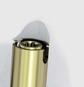
60 Insert End Cap 1. Insert end cap Instruments T-Handle Ball Hex Screwdriver 8 mm Cannulated STARDRIVE Screwdriver/ T40/ 277 mm mm Guide Wire 400 mm Use of an end cap is recommended if bony ingrowth into the proximal end of the nail is of concern. Also, in reverse oblique intertrochanteric and high subtrochanteric fractures, the nail should be slightly proud of the greater trochanter to provide an added point of fixation. If the nail has been over inserted, it should be extended by the use of an end cap of appropriate length. Note: The insertion depth of the nail is indicated by the rings on the insertion handle. Starting distally, each ring is an additional 5 mm from the tip of the nail. This will help in end cap selection. Inserting the 0 mm end cap. Inserting the 0 mm end cap Remove the connecting screw using the ball hexagonal screwdriver while leaving the insertion handle connected to the nail. Insert the 0 mm end cap using the cannulated STARDRIVE Screwdriver through the insertion handle. A 3.2 mm guide wire can be used to help ensure alignment while inserting the end cap. After the end cap is inserted, remove the insertion handle from the nail. Inserting the 5 15 mm end cap Remove the connecting screw and insertion handle using the ball hexagonal screwdriver. Insert the end cap using the cannulated STARDRIVE Screwdriver. A 3.2 mm guide wire can be used to help ensure alignment while inserting the end cap. Inserting the 5 15 mm end cap. Note: In case of difficulties to remove the connecting screw, push the insertion handle towards medial or lateral to neutralize soft tissue pressure. TFN-ADVANCED Proximal Femoral Nailing System (TFNA) Surgical Technique DePuy Synthes 73


61 Implant Removal 1. Disengage locking mechanism Instruments mm Hex Flexible Screwdriver Helical Blade/Screw Extractor Nail Extractor Cannulated STARDRIVE Screwdriver/ T40/ 277 mm * Guide Wire 2.8 mm Length 460 mm with Hook Note: Implant removal steps are consistent for both augmented and non-augmented hardware removal. Use the cannulated STARDRIVE Screwdriver to remove the end cap, optionally assisted by use of the guide wire with hook. In case of ingrown tissue or blockage with cement clean the recess with a sharp hook. Do not yet extract the screw/blade. Turning counterclockwise, thread the helical blade/screw extractor into the end of the helical blade or screw. Do not yet extract the helical blade/screw. Thread the nail extractor into the top of the nail. Pass the 5 mm hex flexible screwdriver through the nail extractor and engage the hex in the locking mechanism. Turn the locking mechanism counterclockwise until it stops. The locking mechanism is disengaged. Note: It may be easier to align the nail extractor if the flexible screwdriver is passed through the nail extractor first and then both instruments engage in the top of the nail. Precaution: Do not attempt to remove the nail at this point. Do not yet extract the nail. *Also available. 60 DePuy Synthes TFN-ADVANCED Proximal Femoral Nailing System (TFNA) Surgical Technique

62 Implant Removal 2. Remove helical blade or screw and distal locking screw Instruments Helical Blade/Screw Extractor Spiral Combination Hammer 500 Grams STARDRIVE Screwdriver/T25/ Self Retaining/320 mm * Hammer Guide Optional instrument Helical Blade/Screw Coupling Screw For the blade, slide the spiral combination hammer over the helical blade/screw extractor and using light hammer blows, hammer until the blade is removed from the bone. Note: The hammer guide may be threaded in the back of the helical blade/screw extractor to extend the working length and thus support the removal. For the screw, continue to turn counterclockwise with a slight pulling force until the screw is removed from the bone. Remove the distal locking screw using the screwdriver. Notes: For the augmented blade, in the unlikely event that the TRAUMACEM V+ Injectable Bone Cement has filled the cannula covering the internal threads and thus preventing the Helical Blade/ Screw Extractor from engaging the blade, thread the coupling screw into the back of the blade and finger tighten. Then attach the driving cap/ threaded to the back of the coupling screw and use the spiral combination hammer (500g) to backslap if needed. *Also available. For the augmented screw, in the unlikely event that the TRAUMACEM V+ Injectable Bone Cement has filled the cannula covering the internal threads and thus preventing the Helical Blade/ Screw Extractor from engaging the screw, insert the cannulated coupling screw and thread in until fully captured in the screw inserter. The coupling screw will remain attached to the inserter. Align the inserter with the back end of the screw. Further thread the coupling screw into the screw and finger tighten the assembly. Turn the inserter counter clockwise with a slight pulling force to remove the screw. TFN-ADVANCED Proximal Femoral Nailing System (TFNA) Surgical Technique DePuy Synthes 61

63 Implant Removal Remove helical blade or screw from the extractor Instrument Combination Wrench 11 mm/blade Screw The end of the combination wrench marked BLADE/ SCREW can be attached to the blade or screw and then used to disengage the helical blade or screw from the helical blade/ screw extractor. Rotate clockwise as the blade and screw have a left-handed thread for removal. 3. Extract nail Instruments * Hammer Guide Spiral Combination Hammer 500 Grams To remove the nail, thread the hammer guide onto the back end of the nail extractor. Attached the spiral combination hammer to the hammer guide and then use light hammer blows to extract the nail. After the nail has been extracted from the bone, dissemble the extractor from the nail. *Also available. 62 DePuy Synthes TFN-ADVANCED Proximal Femoral Nailing System (TFNA) Surgical Technique
64 Implant Removal Alternative Technique Extraction Hook for removal of broken nail Instruments Extraction Hook for TI Cannulated Nails* Universal Chuck with T-Handle Begin with Steps 1 and 2 of Implant Removal. Option 1 1. Assemble extraction hook and universal chuck Insert the extraction hook into the universal chuck with T-Handle. The hook should be parallel with the T-Handle. This facilitates visualization of the hook position in the bone. 2. Insert extraction hook through nail Remove the nail extractor and pass the extraction hook through the cannula of the nail, including the distant fragment. Note: Under image intensification, verify that the hook has passed through and engaged the distant end of the nail. 3. Extract nail Extract both nail fragments. Note: Keep the patient s limb restrained to increase the efficiency of the extraction force. *Also available. TFN-ADVANCED Proximal Femoral Nailing System (TFNA) Surgical Technique DePuy Synthes 63
65 Implant Removal Alternative Technique Extraction Hook for removal of broken nail Option 2 1. Remove near nail fragment Remove the near nail fragment using the technique described in step 3 of the implant removal. Note: The extraction hook can be used as an alternative to extraction instrumentation. 2. Ream canal Ream the medullary canal 1 mm larger than the nail diameter to clear a path for the distant nail fragment. 3. Align extraction hook Insert the extraction hook and explanted near nail fragment into the medullary canal. The near nail fragment aligns the extraction hook with the cannulation of the distant nail fragment. 4. Engage distant fragment Pass the extraction hook through the cannula of the distant nail fragment. Note: Under image intensification, verify that the hook has passed through and engaged the distant end of the nail. 5. Extract nail Extract both nail fragments. Note: Keep the patient s limb restrained to increase the efficiency of the extraction force. 66 DePuy Synthes TFN-ADVANCED Proximal Femoral Nailing System (TFNA) Surgical Technique

66 Checking Drill Stop Wear Instruments mm/9 mm Cannulated Stepped Drill Bit Drill Stop for Possible damage If excessive wear occurs, the drill stop can slip, resulting in incorrect drilling depth. Before use Slide the drill stop onto the drill bit Press on the stop with the thumb without pressing the button. If the stop moves under pressure, replace it Do the same test in the opposite direction. If the stop moves, replace it Recommendations Drill only under periodic image intensifier control While drilling, do not force Replace drill stops that do not pass the described wear test TFN-ADVANCED Proximal Femoral Nailing System (TFNA) Surgical Technique DePuy Synthes 67


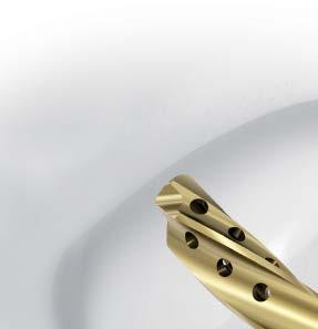
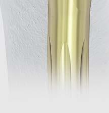
67 Implants TFN-ADVANCED Proximal Femoral Nailing System, Long Nails Features of the long 9 mm 14 mm Cannulated Nails, 300 mm 480 mm lengths (20 mm increments) Proximal diameter of mm Anatomic 5 lateral angle Distal diameters of 9 mm, 10 mm, 11 mm, 12 mm, and 14 mm Preassembled locking mechanism for controlling blade rotation and amount of blade travel Anterior Posterior bend 1.0 m radius of curvature Static or dynamic interlocking with controlled dynamization of 10 mm Anatomic 10 anteversion Third distal locking hole is 10 offset from superior, anterior lateral to posterior medial Nail designs for both left and right femurs *LATERAL RELIEF CUT Design 300 mm 480 mm Nails Material Ti-15Mo (TiMo) Green Locking mechanism TAN, CoCr Angles 125, 130 and 135 Distal locking 5.0 mm locking screws, hex or STARDRIVE Recess TFNA Nail Dia. LATERAL RELIEF CUT TM Design* 9 mm 13.4 mm 10 mm 13.7 mm 11 mm 14.1 mm 12 mm 14.5 mm 14 mm 15.2 mm 57 mm 37 mm 27 mm 12 mm 0 mm Static Dynamic 66 DePuy Synthes TFN-ADVANCED Proximal Femoral Nailing System (TFNA) Surgical Technique
68 Implants TFN-ADVANCED Proximal Femoral Nailing System, Long Nails TFN-ADVANCED System, Long Nails, 9 mm distal diameter, sterile Length Femoral Right Left (mm) Neck Angle S S S S S S S S S S S S S S S S S S S S S S S S S S S S S S S S S S S S S S S S S S S S S S S S TFN-ADVANCED System, Long Nails, 10 mm distal diameter, sterile Length Femoral Right Left (mm) Neck Angle S S S S S S S S S S S S S S S S S S S S S S S S S S S S S S S S S S S S S S S S S S S S S S S S For detailed cleaning and sterilization instructions, please refer to: In Canada, the cleaning and sterilization instructions will be provided with the Loaner shipments. TFN-ADVANCED Proximal Femoral Nailing System (TFNA) Surgical Technique DePuy Synthes 67
69 Implants TFN-ADVANCED Proximal Femoral Nailing System, Long Nails TFN-ADVANCED System, Long Nails, 11 mm distal diameter, sterile Length Femoral Right Left (mm) Neck Angle S S S S S S S S S S S S S S S S S S S S S S S S S S S S S S S S S S S S S S S S S S S S S S S S S S S S S S S S S S S S TFN-ADVANCED System, Long Nails, 12 mm distal diameter, sterile Length Femoral Right Left (mm) Neck Angle S S S S S S S S S S S S S S S S S S S S S S S S S S S S S S S S S S S S S S S S TFN-ADVANCED System, Long Nails, 14 mm distal diameter, sterile Length Femoral Right Left (mm) Neck Angle S S S S S S S S S S S S S S S S S S S S DePuy Synthes TFN-ADVANCED Proximal Femoral Nailing System (TFNA) Surgical Technique
70 Implants TFN-ADVANCED Proximal Femoral Nailing System, Short Nails Features of the short 9 mm 12 mm Cannulated Nails, 170 mm, 200 mm and 235 mm lengths Proximal diameter of mm Anatomic 5 lateral angle Distal diameters of 9 mm, 10 mm, 11 mm, and 12 mm Preassembled locking mechanism for controlling blade or screw rotation and amount of blade or screw travel Static interlocking 170 mm Nail 200 mm Nail 235 mm Nail Material Ti-15Mo (TiMo) Green Locking mechanism TAN, CoCr mm mm mm Angles 125, 130 and mm Distal locking 5.0 mm locking screws, hex or STARDRIVE Recess 0 mm 0 mm *LATERAL RELIEF CUT Design TFNA Nail Dia. LATERAL RELIEF CUT Design* 9 mm 13.4 mm 10 mm 13.7 mm 11 mm 14.1 mm 12 mm 14.5 mm 14 mm 15.2 mm TFN-ADVANCED Proximal Femoral Nailing System (TFNA) Surgical Technique DePuy Synthes 63
71 Implants TFN-ADVANCED Proximal Femoral Nailing System, Short Nails TFN-ADVANCED System, Short Nails, 170 mm length, sterile Femoral Dia. (mm) Neck Angle S S S S S S S S S S S S TFN-ADVANCED System, Short Nails, 235 mm length, sterile Dia. Femoral Right Left (mm) Neck Angle S S S S S S S S S S S S S S S S S S S S S S S S TFN-ADVANCED System, Short Nails, 200 mm length, sterile Femoral Dia. (mm) Neck Angle S S S S S S S S S S S S DePuy Synthes TFN-ADVANCED Proximal Femoral Nailing System (TFNA) Surgical Technique
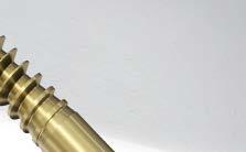
72 Implants Head Elements TFNA Screws Ti-6Al-7Nb (TAN) Color: gold mm diameter 70 mm 130 mm Cannulated TFNA Helical Blades Ti-6Al-7Nb (TAN) Color: gold 70 mm 130 mm (5 mm increments) mm diameter Cannulated Titanium Screws Length Length (mm) (mm) Titanium Helical Blades Length Length (mm) (mm) Titanium End Caps for TFN-ADVANCED Nail, sterile Ti-6Al-7Nb (TAN) Color: green 0 mm (sits flush with nail end) 5 mm/10 mm and 15 mm extensions STARDRIVE Recess T40, hexagonal recess 5.0 mm 15 mm 10 mm 5 mm 0 mm S S S S Extension 0 mm 5 mm 10 mm 15 mm Available nonsterile or sterile-packed. Add S to catalog number to order sterile product. TFN-ADVANCED Proximal Femoral Nailing System (TFNA) Surgical Technique DePuy Synthes 71
 80 mm 100 mm (5 mm increments) STARDRIVE Recess T25 5.0 mm Titanium Locking Screws with Hexagonal Drive Ti-6Al-7Nb (TAN) Light green 4.")
73 Implants Screws Used with the TFN-ADVANCED Proximal Femoral Nailing System 5.0 mm Ti Locking Screws with T25 STARDRIVE Recess for IM Nails Ti-6Al-7Nb (TAN) Light green 4.2 mm diameter drill 26 mm 80 mm (2 mm increments) 80 mm 100 mm (5 mm increments) STARDRIVE Recess T mm Titanium Locking Screws with Hexagonal Drive Ti-6Al-7Nb (TAN) Light green 4.2 mm diameter drill 26 mm 80 mm (2 mm increments) 80 mm 100 mm (5 mm increments) 3.5 hexagonal recess 5.0 mm Ti Locking Screws with T25 StarDrive Recess for IM Nails 5.0 mm Titanium Locking Screws with Hexagonal Drive Length (mm) Length (mm) Length (mm) Length (mm) mm mm mm mm mm mm mm mm mm mm mm mm mm mm mm mm mm mm mm mm mm mm mm mm mm mm mm mm mm mm mm mm mm mm mm mm mm mm mm mm mm mm mm mm mm mm mm mm mm mm Available nonsterile or sterile-packed. Add S to catalog number to order sterile product. 77 DePuy Synthes TFN-ADVANCED Proximal Femoral Nailing System (TFNA) Surgical Technique


74 Implants and Instruments For TRAUMACEM V+ Augmentation System S TRAUMACEM V+ Injectable Bone Cement, sterile Containing: 1 TRAUMACEM V+ mixer with sterilization lid 1 Monomer glass ampoule 1 Cement mixing and transferring lid S TRAUMACEM V+ Syringe Kit, 4 x 1 ml, 2 x 2 ml, sterile Containing: 4 Blue 1 ml syringes 2 White 2 ml syringes 1 One-way stopcock S TRAUMACEM V+ Injection Cannula, for TFNA System, sterile Containing: 1 Side-opening cannula, with Luer-lock 1 Plunger Additionally required: 1 2 Syringes with Luer lock Radiographic contrast agent Saline solution TFN-ADVANCED Proximal Femoral Nailing System (TFNA) Surgical Technique DePuy Synthes 77
75 Instruments mm Three-Fluted Drill Bit quick coupling, 330 mm, 100 mm calibration mm/4.2 mm Drill Sleeve 200 mm mm Trocar 210 mm Depth Gauge for Locking Screws to 100 mm for IM Nails Reaming Rod Push Rod with Ball Handle mm Three-Fluted Drill Bit quick coupling, needle point, 145 mm Direct Measuring Device for Locking Screws to 100 mm for IM Nails 77 DePuy Synthes TFN-ADVANCED Proximal Femoral Nailing System (TFNA) Surgical Technique


76 Instruments Star/HexDrive Screwdriver Shaft T25, 3.5 mm Hexagonal self-retaining, quick coupling, 165 mm Star/HexDrive Screwdriver Shaft T25, 3.5 mm Hexagonal self-retaining, quick coupling, 280 mm Hammer Guide Guide Wire Aiming Device for Trochanteric Fixation Nail for Anterior Posterior orientation Connecting Screw for Guide Wire Aiming Device for Trochanteric Fixation Nail, Anterior Posterior orientation Guide Wire Aiming Device Offset Block Inter-lock Screwdriver T25 StarDrive/ 3.5 mm Hexagonal, 224 mm TFN-ADVANCED Proximal Femoral Nailing System (TFNA) Surgical Technique DePuy Synthes 77


77 Instruments Long Scalpel Handle Depth Gauge for Locking Screws to 100 mm T-Handle Cannulated, with quick coupling T-Handle Ball Hex Screwdriver 8 mm Screwdriver self-retaining, T25, 320 mm Screwdriver T40, 277 mm Spiral Combination Hammer 500 grams 76 DePuy Synthes TFN-ADVANCED Proximal Femoral Nailing System (TFNA) Surgical Technique


78 Instruments Driving Cap threaded mm/8.0 mm Protection Sleeve 188 mm for Angular Stable Locking System Multi Hole Wire Guide 136 mm mm Protection Sleeve 118 mm mm Cannulated Flexible Drill Bit Large Quick Coupling 266 mm mm Cannulated Curved Awl Cannulated Connecting Screw TFN-ADVANCED Proximal Femoral Nailing System (TFNA) Surgical Technique DePuy Synthes 77


79 Instruments Complete Radiolucent Insertion Handle Degree Aiming Arm Aiming Arm Locking Device Buttress Compression Nut Blade/Screw Guide Sleeve mm Wire Guide Sleeve 248 mm mm Trocar 270 mm 77 DePuy Synthes TFN-ADVANCED Proximal Femoral Nailing System (TFNA) Surgical Technique
 03.037.024 Helical Blade Inserter for Trochanteric Fixation Nail Advanced 03.037.025 Screw Inserter 03.037.026 Helical Blade and Screw Coupling Screw TFN-ADVANCED Proximal Femoral Nailing System (TFNA) Surgical Technique DePuy Synthes 77")
80 Instruments Helical Blade and Screw Measuring Device mm Cannulated Tapered Drill Bit large quick coupling, 300 mm mm/9 mm Cannulated Stepped Drill Bit large quick coupling, 500 mm Drill Stop for use with 6 mm/9 mm cannulated stepped drill bit ( ) Helical Blade Inserter for Trochanteric Fixation Nail Advanced Screw Inserter Helical Blade and Screw Coupling Screw TFN-ADVANCED Proximal Femoral Nailing System (TFNA) Surgical Technique DePuy Synthes 77

 Surgical Technique")
81 Instruments Tap for Screw mm Hexagonal Flexible Screwdriver mm Hexagonal Screwdriver Shaft Helical Blade and Screw Extractor for use with Trochanteric Fixation Nail Advanced System Combination Wrench 11 mm for blade and screws Nail Extractor Depth Gauge for Trochanteric Nailing System 70 DePuy Synthes TFN-ADVANCED Proximal Femoral Nailing System (TFNA) Surgical Technique


82 Instruments Compression Nut for use with Trochanteric Fixation Nail Advanced Screw Inserter Threaded Hammer Guide Connector Torque Limiting Attachment 6Nm for AO Reaming Coupler mm Pin Wrench 120 mm Depth Gauge Extension Tube for use with or mm Guide Wire 400 mm mm/3.2 mm Drill Guide 198 mm TFN-ADVANCED Proximal Femoral Nailing System (TFNA) Surgical Technique DePuy Synthes 71


83 Instruments mm Hexagonal Shaft 210 mm Universal Chuck with T-Handle 72 DePuy Synthes TFN-ADVANCED Proximal Femoral Nailing System (TFNA) Surgical Technique
84 Also Available TFNA Screws Ti-6Al-7Nb (TAN) Color: gold mm diameter 70 mm 130 mm Cannulated TFNA Helical Blades Ti-6Al-7Nb (TAN) Color: gold 70 mm 130 mm (5 mm increments) mm diameter Cannulated Titanium Screws Length Length (mm) (mm) Titanium Helical Blades Length Length (mm) (mm) Available nonsterile or sterile-packed. Add S to catalog number to order sterile product. TFN-ADVANCED Proximal Femoral Nailing System (TFNA) Surgical Technique DePuy Synthes 73


85 Also Available mm Cannulated Drill Bit mm Cannulated Hollow Drill Bit large quick coupling, 214 mm Reamer Protection Tube Trocar for Protection Tube Hybrid Insertion Handle Degree Screw Only Aiming Arm 74 DePuy Synthes TFN-ADVANCED Proximal Femoral Nailing System (TFNA) Surgical Technique

86 TFNA Standard Instrument Set ( ) Graphic Cases Full Length Graphic Case 2-high Full Length Graphic Case 3-high Opening Tray for TFN-Advanced Nail Insertion Tray for TFN-Advanced Blade/Screw Insertion Tray for TFN-Advanced Locking Tray for TFN-Advanced TFNA Complete Set Graphic Case Label Sheet Instruments mm Three-Fluted Drill Bit quick coupling, 330 mm, 100 mm calibration mm/4.2 mm Drill Sleeve 200 mm mm Trocar 210 mm Depth Gauge for Locking Screws to 100 mm for IM Nails Reaming Rod Push Rod with Ball Handle mm Three-Fluted Drill Bit quick coupling, needle point, 145 mm Direct Measuring Device for Locking Screws to 100 mm for IM Nails Star/HexDrive Screwdriver Shaft T25, 3.5 mm Hexagonal self-retaining, quick coupling, 165 mm Star/HexDrive Screwdriver Shaft T25, 3.5 mm Hexagonal self-retaining, quick coupling, 280 mm Hammer Guide Guide Wire Aiming Device for Trochanteric Fixation Nail for Anterior Posterior orientation Connecting Screw for Guide Wire Aiming Device for Trochanteric Fixation Nail, Anterior Posterior orientation Guide Wire Aiming Device Offset Block For detailed cleaning and sterilization instructions, please refer to or sterilization instructions, if provided Inter-lock Screwdriver T25 StarDrive/ 3.5 mm Hexagonal, 224 mm Long Scalpel Handle T-Handle Cannulated, with quick coupling T-Handle Ball Hex Screwdriver 8 mm Screwdriver self retaining, T25, 319 mm Screwdriver T40, 277 mm Spiral Combination Hammer 500 grams Driving Cap threaded mm/8.0 mm Protection Sleeve 188 mm for Angular Stable Locking System Multi Hole Wire Guide 136 mm mm Protection Sleeve 118 mm mm Cannulated Flexible Drill Bit Large Quick Coupling mm mm Cannulated Drill Bit Large Quick Coupling mm Reamer Protection Tube 160 mm Radiographic Ruler TFN-ADVANCED Proximal Femoral Nailing System (TFNA) Surgical Technique DePuy Synthes 77
87 TFNA Standard Instrument Set ( ) mm Cannulated Curved AWL Cannulated Connecting Screw, 2 ea Complete Radiolucent Insertion Handle Degree Aiming Arm Aiming Arm Locking Device Buttress Compression Nut Blade/Screw Guide Sleeve mm Wire Guide Sleeve 248 mm mm Trocar 270 mm Helical Blade and Screw Measuring Device mm Cannulated Tapered Drill Bit large quick coupling, 300 mm mm/9 mm Cannulated Stepped Drill Bit large quick coupling, 500 mm Drill Stop for use with 6 mm/9 mm cannulated stepped drill bit ( ) Helical Blade Inserter for Trochanteric Fixation Nail Advanced Screw Inserter Helical Blade and Screw Coupling Screw Tap for Screw mm Hexagonal Flexible Screwdriver mm Hexagonal Screwdriver Shaft Helical Blade and Screw Extractor Combination Wrench 11 mm for blade and screws Nail Extractor Depth Gauge for Trochanteric Nailing System Trocar For Protection Tube Compression Nut Threaded Hammer Guide Connector, 2 ea Torque Limiting Attachment 6Nm for AO Reaming Coupler mm Pin Wrench 120 mm Depth Gauge Extension Tube for use with or mm Guide Wire 400 mm, 10 ea mm/3.2 mm Drill Guide 198 mm, 2 ea mm Hexagonal Shaft 210 mm Universal Chuck with T-Handle 88 DePuy Synthes TFN-ADVANCED Proximal Femoral Nailing System (TFNA) Surgical Technique

88 TFNA Standard Instrument Set ( ) Graphic Cases Full Length Graphic Case 1-high Percutaneous Instrument Tray for TFN-Advanced Instruments mm Guide Wire 475 mm, 5 ea Percutaneous Multi Hole Wire Guide 260 mm mm Percutaneous Sleeve 242 mm mm Cannulated Percutaneous Flexible Drill Bit large quick coupling, 390 mm mm Cannulated Percutaneous Drill Bit large quick coupling, 390 mm Percutaneous Radiolucent Insertion Handle TFN-ADVANCED Proximal Femoral Nailing System (TFNA) Surgical Technique DePuy Synthes 88
 04.038.370 70 mm 04.038.375 75 mm 04.038.380 80 mm 04.038.385 85 mm 04.038.390 90 mm 04.038.395 95 mm 04.038.400 100 mm TFN-ADVANCED Screws Length (mm) 04.")
89 TFN-ADVANCED Implant Set ( ) Graphic Cases Graphic Case/Full Length 1-high TFNA Implant Tray for TFN-Advanced TFN-Advanced Complete Set Graphic Case Label Sheet Instruments Screw Forceps Implants TFN-ADVANCED Helical Blades Length (mm) mm mm mm mm mm mm mm TFN-ADVANCED Screws Length (mm) mm mm mm mm mm mm mm Length (mm) mm mm mm mm mm mm Length (mm) mm mm mm mm mm mm 5.0 mm Ti Locking Screws with T25 STARDRIVE Recess for IM Nails, 2 ea. Length (mm) mm mm mm mm mm mm mm mm mm mm mm mm mm Length (mm) mm mm mm mm mm mm mm mm mm mm mm mm Available nonsterile or sterile-packed. Add S to catalog number to order sterile product. 88 DePuy Synthes TFN-ADVANCED Proximal Femoral Nailing System (TFNA) Surgical Technique
For intramedullary fixation of proximal femoral fractures SURGICAL TECHNIQUE
 For intramedullary fixation of proximal femoral fractures SURGICAL TECHNIQUE TABLE OF CONTENTS INTRODUCTION Clinical Cases 2 AO Principles 4 Indications and Precautions 5 SURGICAL TECHNIQUE Preparation
TFNA PROXIMAL FEMORAL NAILING SYSTEM
 TFNA PROXIMAL FEMORAL NAILING SYSTEM For Intramedullary Fixation of Proximal Femoral Fractures Instruments and implants approved by the AO Foundation. This publication is not intended for distribution
SURGICAL TECHNIQUE. For Intramedullary Fixation of Proximal Femoral Fractures
 For Intramedullary Fixation of Proximal Femoral Fractures Instruments and implants approved by the AO Foundation. This publication is not intended for distribution in the USA. SURGICAL TECHNIQUE Image
For Intramedullary Fixation of Proximal Femoral Fractures. TFNAdvanced. Surgical Technique for TFNA Screw only
 For Intramedullary Fixation of Proximal Femoral Fractures TFNAdvanced Surgical Technique for TFNA Screw only Image intensifier control This description alone does not provide sufficient background for
Femoral Recon Nail System FRN
 Greater Trochanter Piriformis Fossa Approaches For Intramedullary Fixation of Femoral Shaft Fractures Femoral Recon Nail System FRN Surgical Technique Table of Contents AO Principles 2 Indications and
Femoral Recon Nail System FRN
 Greater Trochanter Piriformis Fossa Approaches For Intramedullary Fixation of Femoral Shaft Fractures Femoral Recon Nail System FRN Surgical Technique Image intensifier control This description alone does
Titanium Cannulated Lateral Entry Femoral Recon Nail
 Expert Nailing System Titanium Cannulated Lateral Entry Femoral Recon Nail Surgical Technique Table of Contents Introduction Titanium Cannulated Lateral Entry 2 Femoral Recon Nail Expert System AO Principles
Titanium Distal Femoral Nail System
 For Retrograde Insertion Titanium Distal Femoral Nail System Surgical Technique Table of Contents Introduction Titanium Distal Femoral Nail System 2 AO Principles 4 Indications 5 Clinical Cases 6 Surgical
Expert A2FN. Designed for small statured patients.
 Expert A2FN. Designed for small statured patients. Surgical Technique Expert Nailing System This publication is not intended for distribution in the USA. Instruments and implants approved by the AO Foundation.
3.5 mm LCP Low Bend Medial Distal Tibia Plate Aiming Instruments
 Part of the 3.5 mm LCP 3.5 mm LCP Low Bend Medial Distal Tibia Plate Aiming Instruments Surgical Technique TABLE OF CONTENTS INTRODUCTION 3.5 mm LCP Low Bend Medial Distal Tibia Plate 2 Aiming Instruments
Titanium Cannulated Retrograde/ Antegrade Femoral Nail
 Expert Nailing System With Radiolucent Instrumentation Titanium Cannulated Retrograde/ Antegrade Femoral Nail Surgical Technique Table of Contents Introduction Titanium Cannulated Retrograde/Antegrade
LCP Low Bend Medial Distal Tibia Plates 3.5 mm. Anatomic plates with low profile head for intra- and extraarticular fractures.
 LCP Low Bend Medial Distal Tibia Plates 3.5 mm. Anatomic plates with low profile head for intra- and extraarticular fractures. Surgical Technique This publication is not intended for distribution in the
Orthopedic Bone Nail System - Distal Femoral Nail Surgical Technique Manual
 Orthopedic Bone Nail System - Distal Femoral Nail Surgical Technique Manual Note: The surgical procedures should be performed under the guidance of qualified skilled orthopedic surgeons, and this surgical
Technique Guide. LCP Proximal Femoral Hook Plate 4.5/5.0. Part of the LCP Periarticular Plating System.
 Technique Guide LCP Proximal Femoral Hook Plate 4.5/5.0. Part of the LCP Periarticular Plating System. Table of Contents Introduction Features and Benefits 2 AO ASIF Principles 4 Indications 5 Surgical
3. PATIENT POSITIONING & FRACTURE REDUCTION 3 8. DISTAL GUIDED LOCKING FOR PROXIMAL NAIL PROXIMAL LOCKING FOR LONG NAIL 13
 Contents IMPLANT FEATURES 2 1. INDICATIONS 3 2. PRE-OPERATIVE PLANNING 3 3. PATIENT POSITIONING & FRACTURE REDUCTION 3 4. INCISION 4 5. ENTRY POINT 4-6 6. PROXIMAL NAIL INSERTION 6-7 7. PROXIMAL LOCKING
Low Bend Distal Tibia Plates
 Part of the DePuy Synthes Locking Compression Plate (LCP ) System 3.5 mm LCP Low Bend Medial Distal Tibia Plates Surgical Technique Table of Contents Introduction 3.5 mm LCP Low Bend Medial Distal Tibia
3.5 mm LCP Extra-articular Distal Humerus Plate
 Part of the DePuy Synthes Locking Compression Plate (LCP ) System 3.5 mm LCP Extra-articular Distal Humerus Plate Surgical Technique Table of Contents Introduction 3.5 mm LCP Extra-articular Distal Humerus
System. Humeral Nail. Surgical Technique
 System Humeral Nail Surgical Technique Contents IMPLANT FEATURES 2 1. INDICATIONS 3 2. PRE-OPERATIVE PLANNING 3 3. PATIENT POSITIONING & FRACTURE REDUCTION 3 4. INCISION 4 5. ENTRY POINT 4-6 6. PROXIMAL
Technique Guide. 3.5 mm LCP Low Bend Medial Distal Tibia Plate Aiming Instruments. Part of the 3.5 mm LCP Percutaneous Instrument System.
 Technique Guide 3.5 mm LCP Low Bend Medial Distal Tibia Plate Aiming Instruments. Part of the 3.5 mm LCP Percutaneous Instrument System. Table of Contents Introduction 3.5 mm LCP Low Bend Medial Distal
PROXIMAL FEMORAL NAIL REMOVAL SET
 PROXIMAL FEMORAL NAIL REMOVAL SET for PFN, TFN and PFNA/PFNA-II Instruments and Implants approved by the AO Foundation. This publication is not intended for distribution in the USA. SURGICAL TECHNIQUE
With Augmentation Option PFNA. Surgical Technique
 With Augmentation Option PFNA Surgical Technique Image intensifier control This description alone does not provide sufficient background for direct use of DePuy Synthes products. Instruction by a surgeon
Zimmer Natural Nail System
 Zimmer Natural Nail System Antegrade Femoral Nail Surgical Technique (Piriformis Fossa & Greater Trochanteric Approaches) Zimmer Natural Nail System Antegrade Femoral Surgical Technique 1 Zimmer Natural
Expert A2FN. Designed for small statured patients.
 Expert A2FN. Designed for small statured patients. Technique Guide Expert Nailing System This publication is not intended for distribution in the USA. Instruments and implants approved by the AO Foundation
Olecranon Osteotomy Nail. For simple fractures and osteotomies of the olecranon.
 Olecranon Osteotomy Nail. For simple fractures and osteotomies of the olecranon. Technique Guide Discontinued June 2016; AVAILABLE FOR IMPLANT REMOVAL PURPOSES ONLY DSEM/TRM/0517/0843 Table of Contents
TITANIUM TIBIAL NAIL SySTEM
 TITANIUM TIBIAL NAIL SySTEM Solid and Cannulated Nails SURGICAL TEChNIqUE Table of contents Introduction Indications 2 Preoperative Implant Selection 6 Surgical Technique Instruments for Opening the Tibia
Cannulated Pediatric Osteotomy System (CAPOS)
") A Single System of Osteotomy Blade Plates and Cannulated Instrumentation Cannulated Pediatric Osteotomy System (CAPOS) Surgical Technique Table of Contents Introduction Cannulated Pediatric Osteotomy System
A Single System of Osteotomy Blade Plates and Cannulated Instrumentation Cannulated Pediatric Osteotomy System (CAPOS) Surgical Technique Table of Contents Introduction Cannulated Pediatric Osteotomy System
titanium cannulated adolescent lateral entry femoral nail
 titanium cannulated adolescent lateral entry femoral nail Expert Nailing System with Radiolucent Instrumentation SurgIcal technique Table of Contents Introduction Titanium Cannulated Adolescent Lateral
Periarticular Aiming Arm Instruments for LCP Proximal Tibial Plate 4.5/5.0. Part of the LCP Periarticular Aiming Arm Instrument System (large).
.") Technique Guide Periarticular Aiming Arm Instruments for LCP Proximal Tibial Plate 4.5/5.0. Part of the LCP Periarticular Aiming Arm Instrument System (large). Image intensifier control Warning This description
Technique Guide Periarticular Aiming Arm Instruments for LCP Proximal Tibial Plate 4.5/5.0. Part of the LCP Periarticular Aiming Arm Instrument System (large). Image intensifier control Warning This description
3.5 mm LCP Olecranon Plates
 Part of the DePuy Synthes Locking Compression Plate (LCP ) System 3.5 mm LCP Olecranon Plates Surgical Technique Table of Contents Introduction 3.5 mm LCP Olecranon Plates 2 AO Principles 3 Indications
3.5 MM VA-LCP PROXIMAL TIBIA PLATE SYSTEM
 3.5 MM VA-LCP PROXIMAL TIBIA PLATE SYSTEM Part of the DePuy Synthes Variable Angle Periarticular Plating System SURGICAL TECHNIQUE TABLE OF CONTENTS INTRODUCTION 3.5 mm VA-LCP Proximal Tibial Plate 2 AO
Titanium Cannulated Adolescent Lateral Entry Femoral Nail. Expert Nailing System.
 Titanium Cannulated Adolescent Lateral Entry Femoral Nail. Expert Nailing System. Technique Guide EXPERT Nailing System Table of Contents Introduction Titanium Cannulated Adolescent Lateral Entry 2 Femoral
Femoral Neck System. Surgical Technique
 Femoral Neck System Surgical Technique Image intensifier control This description alone does not provide sufficient background for direct use of DePuy Synthes products. Instruction by a surgeon experienced
PediNail Pediatric Femoral Nail
 PediNail Pediatric Femoral Nail Surgical Technique Table of Contents Indications...3 Patient Positioning...3 Approach...4 Reaming...5 Nail Placement...6 Proximal Interlocking...7 Distal Interlocking...8
Zimmer ITST Intertrochanteric/ Subtrochanteric Fixation System. Abbreviated Surgical Technique
 Zimmer ITST Intertrochanteric/ Subtrochanteric Fixation System Abbreviated Surgical Technique ITST System Abbreviated Surgical Technique Indications The ITST Intramedullary Nail is indicated for use in
Technique Guide. SureLock Distal Targeting Device. C-arm guided targeting for trochanteric fixation nail.
 Technique Guide SureLock Distal Targeting Device. C-arm guided targeting for trochanteric fixation nail. Table of Contents Introduction SureLock Distal Targeting Device 2 Surgical Technique Preoperative
2.7 mm/3.5 mm LCP Distal Fibula Plate
 Part of the DePuy Synthes Locking Compression Plate (LCP ) System 2.7 mm/3.5 mm LCP Distal Fibula Plate Surgical Technique Table of Contents Introduction 2.7 mm/3.5 mm LCP Distal Fibula Plates 2 AO Principles
designed to advance the treatment of hip fractures.
 designed to advance the treatment of hip fractures. introducing the tfn-advanced proximal femoral nailing system (tfna). the tfna system is a new system designed to solve a wide range of unmet needs for
Expert ALFN. Adolescent Lateral Femoral Nail
 Expert ALFN. Adolescent Lateral Femoral Nail Surgical Technique EXPERT Nailing System This publication is not intended for distribution in the USA. Instruments and implants approved by the AO Foundation
Surgical Technique. CONQUEST FN Femoral Neck Fracture System
 Surgical Technique CONQUEST FN Femoral Neck Fracture System Table of Contents Introduction... 3 Indications... 3 Product Overview... 4 Surgical Technique... 5 Patient Positioning... 5 Reduce the Fracture...
Part of the DePuy Synthes Locking Compression Plate (LCP ) System. 3.5 mm LCP Medial Proximal Tibia Plates
 System. 3.5 mm LCP Medial Proximal Tibia Plates") Part of the DePuy Synthes Locking Compression Plate (LCP ) System 3.5 mm LCP Medial Proximal Tibia Plates Surgical Technique Table of Contents Introduction 3.5 mm LCP Medial Proximal Tibia Plates 2 AO
Part of the DePuy Synthes Locking Compression Plate (LCP ) System 3.5 mm LCP Medial Proximal Tibia Plates Surgical Technique Table of Contents Introduction 3.5 mm LCP Medial Proximal Tibia Plates 2 AO
4.5 mm LCP Medial Proximal Tibia Plates
 Part of the DePuy Synthes LCP Periarticular Plating System 4.5 mm LCP Medial Proximal Tibia Plates Surgical Technique Table of Contents Introduction 4.5 mm LCP Medial Proximal Tibia Plates 2 AO Principles
4.5 mm LCP Condylar Plate Aiming Instruments
 Part of the LCP Periarticular Aiming Instrument System (Large) 4.5 mm LCP Condylar Plate Aiming Instruments Surgical Technique Table of Contents Introduction 4.5 mm LCP Condylar Plate Aiming Instruments
The Titanium Tibial Nail System
 The Titanium Tibial Nail System Solid Tibial Nails (UTN) and Cannulated Tibial Nails (CTN) Surgical Technique This publication is not intended for distribution in the USA. Instruments and implants approved
Technique Guide. 3.5 mm LCP Low Bend Medial Distal Tibia Plates. Part of the Synthes locking compression plate (LCP) system.
 system.") Technique Guide 3.5 mm LCP Low Bend Medial Distal Tibia Plates. Part of the Synthes locking compression plate (LCP) system. Table of Contents Introduction 3.5 mm LCP Low Bend Medial Distal Tibia Plates
Technique Guide 3.5 mm LCP Low Bend Medial Distal Tibia Plates. Part of the Synthes locking compression plate (LCP) system. Table of Contents Introduction 3.5 mm LCP Low Bend Medial Distal Tibia Plates
LCP DISTAL TIBIA PLATE
 LCP DISTAL TIBIA PLATE Instruments and implants approved by the AO Foundation. This publication is not intended for distribution in the USA. SURGICAL TECHNIQUE Image intensifier control This description
Expert ALFN. Adolescent Lateral Femoral Nail.
 Expert ALFN. Adolescent Lateral Femoral Nail. Surgical Technique EXPERT Nailing System This publication is not intended for distribution in the USA. Instruments and implants approved by the AO Foundation.
Sirus Antegrade Femoral Nail System Surgical Technique
 Sirus Antegrade Femoral Nail System Surgical Technique The Cannulated Titanium Nail with Anatomical Shape and Lateral Entry Point Disclaimer This document is intended exclusively for experts in the field,
PFNA-II. Proximal Femoral Nail Antirotation.
 PFNA-II. Proximal Femoral Nail Antirotation. Technique Guide This publication is not intended for distribution in the USA. Instruments and implants approved by the AO Foundation. Image intensifier control
Conventus CAGE PH Surgical Techniques
 Conventus CAGE PH Surgical Techniques Conventus Orthopaedics The Conventus CAGE PH (PH Cage) is a permanent implant comprised of an expandable scaffold, made from nitinol and titanium, which is deployed
The Locking Calcaneal Plate Instrument and Implant Sets
 Part of the DePuy Synthes Locking Compression Plate (LCP ) System The Locking Calcaneal Plate Instrument and Implant Sets Surgical Technique Table of Contents Introduction Locking Calcaneal Plate 2 AO
LCP Proximal Tibial Plate 4.5/5.0 with Periarticular Aiming Arm Instruments
 LCP Proximal Tibial Plate 4.5/5.0 with Periarticular Aiming Arm Instruments Surgical Technique This publication is not intended for distribution in the USA. Instruments and implants approved by the AO
LCP Medial Distal Tibia Plate, without Tab. The Low Profile Anatomic Fixation System with Angular Stability and Optimal Screw Orientation.
 LCP Medial Distal Tibia Plate, without Tab. The Low Profile Anatomic Fixation System with Angular Stability and Optimal Screw Orientation. Technique Guide LCP Small Fragment System Table of Contents Introduction
LCP Medial Proximal Tibial Plate 4.5/5.0. Part of the Synthes LCP periarticular plating system.
 LCP Medial Proximal Tibial Plate 4.5/5.0. Part of the Synthes LCP periarticular plating system. Technique Guide This publication is not intended for distribution in the USA. Instruments and implants approved
LCP Medial Proximal Tibial Plate 3.5. Part of the Synthes small fragment Locking Compression Plate (LCP) system.
 system.") LCP Medial Proximal Tibial Plate 3.5. Part of the Synthes small fragment Locking Compression Plate (LCP) system. Technique Guide This publication is not intended for distribution in the USA. Instruments
LCP Medial Proximal Tibial Plate 3.5. Part of the Synthes small fragment Locking Compression Plate (LCP) system. Technique Guide This publication is not intended for distribution in the USA. Instruments
Long Volar Plates for Diaphyseal-Metaphyseal Radius Fractures LCP. Dia-Meta Volar Distal Radius Plates. Surgical Technique
 Long Volar Plates for Diaphyseal-Metaphyseal Radius Fractures LCP Dia-Meta Volar Distal Radius Plates Surgical Technique Table of Contents Introduction LCP Dia-Meta Volar Distal Radius Plates 2 AO Principles
PFN. Proximal Femoral Nail Standard/Short, PFN Long PFN
 PFN. Proximal Femoral Nail Standard/Short, PFN Long PFN Surgical Technique This publication is not intended for distribution in the USA. Instruments and implants approved by the AO Foundation. 357.001
2.4 mm Variable Angle LCP Volar Extra-Articular Distal Radius System. For fragment-specific fracture fixation with variable angle locking technology.
 2.4 mm Variable Angle LCP Volar Extra-Articular Distal Radius System. For fragment-specific fracture fixation with variable angle locking technology. Surgical Technique This publication is not intended
Expert R/AFN. Retrograde/Antegrade Femoral Nail.
 Expert R/AFN. Retrograde/Antegrade Femoral Nail. Surgical Technique EXPERT Nailing System This publication is not intended for distribution in the USA. Instruments and implants approved by the AO Foundation
OPERATING MANUAL AND TECHNIQUE GUIDE FOR TITANIUM FEMORAL AND TIBIAL NAILING SYSTEMS
 OPERATING MANUAL AND TECHNIQUE GUIDE FOR TITANIUM FEMORAL AND TIBIAL NAILING SYSTEMS ORTHO-MEDICAL GMBH TITANIUM FEMORAL NAIL OPERATIVE TECHNIQUE Introduction: Why a new type of femoral nail? The latest
Double Engine Orthopedic Bone Nail System Universal Humeral Nail
 Double Engine Orthopedic Bone Nail System ----------- Universal Humeral Nail Surgical Technique Manual Note: The surgical procedures should be performed under the guidance of qualified skilled orthopedic
3.5 mm LCP Clavicle Hook Plates
 Part of the Synthes Locking Compression Plate (LCP ) System 3.5 mm LCP Clavicle Hook Plates Surgical Technique Table of Contents Introduction 3.5 mm LCP Clavicle Hook Plates 2 AO Principles 4 Indications
2.7 mm/3.5 mm Variable Angle LCP. Ankle Trauma System
 Part of the DePuy Synthes Variable Angle Locking Compression Plate (VA LCP ) System 2.7 mm/3.5 mm Variable Angle LCP Ankle Trauma System Surgical Technique Table of Contents Introduction 2.7 mm/3.5 mm
NeoGen Tibia Nail System
 NeoGen Tibia Nail System LESS IS MORE TE-2070-03 Surgical Technique BLE OF CONTENT Preface Surgical Technique Appendix Products Information Patient Preparation Entry Portal Fracture Reduction Canal Preparation
Technique Guide. 3.5 mm LCP Proximal Tibia Plate. Part of the Synthes Small Fragment LCP System.
 Technique Guide 3.5 mm LCP Proximal Tibia Plate. Part of the Synthes Small Fragment LCP System. Table of Contents AO ASIF Principles of Internal Fixation 4 Indications/Contraindications 5 Surgical Technique
NeoGen Femoral Nail System
 NeoGen Femoral Nail System LESS IS MORE TE-2070-04 Surgical Technique BLE OF CONTENT Preface Standard Femoral Mode Recon Mode Post-Operative Management Appendix Products Information Indication Patient
The Titanium Cannulated Tibial Nail with Proximal Bend. Expert nailing system.
 The Titanium Cannulated Tibial Nail with Proximal Bend. Expert nailing system. Technique Guide Expert Nailing System Table of Contents Introduction Titanium Cannulated Tibial Nail with 2 Proximal Bend
LCP Anterolateral Distal Tibia Plate 3.5. The low profile anatomic fixation system with optimal plate placement and angular stability.
 LCP Anterolateral Distal Tibia Plate 3.5. The low profile anatomic fixation system with optimal plate placement and angular stability. Technique Guide LCP Small Fragment System Table of Contents Introduction
LCP Condylar Plate 4.5/5.0. Part of the LCP Periarticular Plating System.
 LCP Condylar Plate 4.5/5.0. Part of the LCP Periarticular Plating System. Surgical Technique This publication is not intended for distribution in the USA. Instruments and implants approved by the AO Foundation.
3.5 mm LCP Hook Plate
 Part of the DePuy Synthes Locking Compression Plate (LCP ) System 3.5 mm LCP Hook Plate Surgical Technique Table of Contents Introduction 3.5 mm LCP Hook Plate 2 AO Principles 4 Indications 5 Clinical
Arcos Interlocking Distal Stem. Surgical Technique Addendum to the Arcos Modular Femoral Revision System
 Arcos Interlocking Distal Stem Surgical Technique Addendum to the Arcos Modular Femoral Revision System One Surgeon. One Patient. Over 1 million times per year, Biomet helps one surgeon provide personalized
Cannulated Pediatric Osteotomy System (CAPOS). A single system of osteotomy blade plates and cannulated instrumentation.
. A single system of osteotomy blade plates and cannulated instrumentation.") Cannulated Pediatric Osteotomy System (CAPOS). A single system of osteotomy blade plates and cannulated instrumentation. Surgical Technique This publication is not intended for distribution in the USA.
Cannulated Pediatric Osteotomy System (CAPOS). A single system of osteotomy blade plates and cannulated instrumentation. Surgical Technique This publication is not intended for distribution in the USA.
VA-LCP Anterior Clavicle Plate. The anatomically precontoured fixation system with angular stability for clavicle shaft and lateral clavicle.
 Technique Guide VA-LCP Anterior Clavicle Plate. The anatomically precontoured fixation system with angular stability for clavicle shaft and lateral clavicle. Table of Contents Introduction VA-LCP Anterior
VA-LCP Condylar Plate 4.5/5.0. Part of the Synthes Variable Angle Periarticular Plating System.
 VA-LCP Condylar Plate 4.5/5.0. Part of the Synthes Variable Angle Periarticular Plating System. Technique Guide This publication is not intended for distribution in the USA. Instruments and implants approved
Mandible External Fixator II. Provides treatment for fractures of the maxillofacial area.
 Mandible External Fixator II. Provides treatment for fractures of the maxillofacial area. Technique Guide This publication is not intended for distribution in the USA. Instruments and implants approved
AcUMEDr. FoREARM ROD SYSTEM
 AcUMEDr FoREARM ROD SYSTEM FoREARM ROD SYSTEM Since 1988 Acumed has been designing solutions to the demanding situations facing orthopedic surgeons, hospitals and their patients. Our strategy has been
3.5 mm LCP Distal Humerus Plates
 Part of the DePuy Synthes Locking Compression Plate (LCP ) System 3.5 mm LCP Distal Humerus Plates Surgical Technique Table of Contents Introduction 3.5 mm LCP Distal Humerus Plates 2 AO Principles 4 Indications
LCP Anterolateral Distal Tibia Plate 3.5. The low profile anatomic fixation system with optimal plate placement and angular stability.
 LCP Anterolateral Distal Tibia Plate 3.5. The low profile anatomic fixation system with optimal plate placement and angular stability. Technique Guide LCP Small Fragment System Table of Contents Introduction
Cannulated Pediatric Osteotomy System (CAPOS). A single system of osteotomy blade plates and cannulated instrumentation.
. A single system of osteotomy blade plates and cannulated instrumentation.") Cannulated Pediatric Osteotomy System (CAPOS). A single system of osteotomy blade plates and cannulated instrumentation. Technique Guide This publication is not intended for distribution in the USA. Instruments
Cannulated Pediatric Osteotomy System (CAPOS). A single system of osteotomy blade plates and cannulated instrumentation. Technique Guide This publication is not intended for distribution in the USA. Instruments
3.5 mm LCP Anterolateral Distal Tibia Plates
 Part of the DePuy Synthes Locking Compression Plate (LCP ) System 3.5 mm LCP Anterolateral Distal Tibia Plates Surgical Technique Table of Contents Introduction 3.5 mm LCP Anterolateral Distal Tibia Plates
3.5 mm Locking Attachment Plate
 For Treatment of Periprosthetic Fractures 3.5 mm Locking Attachment Plate Surgical Technique Table of Contents Introduction 3.5 mm Locking Attachment Plate 2 Indications 4 Surgical Technique Preparation
Expert R /AFN Retrograde /Antegrade Femoral Nail.
 Expert R /AFN Retrograde /Antegrade Femoral Nail. Technique Guide Expert Nailing System Table of Contents Introduction Features 2 AO/ASIF principles of internal fixation 7 Indications 9 Cases 10 Retrograde
ANGLED BLADE PLATES FOR ADULTS
 ANGLED BLADE PLATES FOR ADULTS Instruments and implants approved by the AO Foundation. This publication is not intended for distribution in the USA. SURGICAL TECHNIQUE Image intensifier control This description
Antegrade Femoral Nail (AFN)
") Antegrade Femoral Nail (AFN) Surgical Technique This publication is not intended for distribution in the USA. Instruments and implants approved by the AO Foundation. Image intensifier control Warning This
Antegrade Femoral Nail (AFN) Surgical Technique This publication is not intended for distribution in the USA. Instruments and implants approved by the AO Foundation. Image intensifier control Warning This
TABLE OF CONTENTS. 2 (8144 Rev 2)
") 1 (8144 Rev 2) TABLE OF CONTENTS Introduction Conventus CAGE TM - Proximal Humerus...3 Indications and Contraindications...4 Surgical Summary...5 Patient Positioning & Approach...6 Surgical Technique Plate
1 (8144 Rev 2) TABLE OF CONTENTS Introduction Conventus CAGE TM - Proximal Humerus...3 Indications and Contraindications...4 Surgical Summary...5 Patient Positioning & Approach...6 Surgical Technique Plate
Suprapatellar Instrumentation for Titanium Cannulated Tibial Nail. Expert nailing system.
 Suprapatellar Instrumentation for Titanium Cannulated Tibial Nail. Expert nailing system. Technique Guide Expert Nailing System Table of Contents Introduction Suprapatellar Instrumentation for Titanium
Technique Guide. TomoFix Osteotomy System. A comprehensive plating system for stable fixation of osteotomies around the knee.
 Technique Guide TomoFix Osteotomy System. A comprehensive plating system for stable fixation of osteotomies around the knee. Table of Contents Introduction TomoFix Osteotomy System 2 AO Principles 4 Indications
Surgical Technique. Targeter Systems Overview
 Surgical Technique Targeter Systems Overview PERI-LOC Locked Plating System Targeter Systems Overview Table of contents Product overview... 2 Introduction... 2 Indications... 2 Design features and benefits...
Technique Guide. 3.5 mm LCP Olecranon Plates. Part of the Synthes locking compression plate (LCP) system.
 system.") Technique Guide 3.5 mm LCP Olecranon Plates. Part of the Synthes locking compression plate (LCP) system. Table of Contents Introduction 3.5 mm LCP Olecranon Plates 2 AO Principles 3 Indications 3 Clinical
Technique Guide 3.5 mm LCP Olecranon Plates. Part of the Synthes locking compression plate (LCP) system. Table of Contents Introduction 3.5 mm LCP Olecranon Plates 2 AO Principles 3 Indications 3 Clinical
GREENS SURGICALS. Redefining Excellence INSTRUMENT SYSTEM PREPARED BY: DR. VINAY KUMAR
 GREENS SURGICALS Redefining Excellence TIBIA AND FEMUR INSTRUMENT SYSTEM PREPARED BY: DR. VINAY KUMAR OPERATIVE TECHNIQUES INDEX SR.NO CONTENTS 1 LIST OF INSTRUMENT FOR TIBIA AND FEMUR. 2 RADIO GRAPH OF
Surgical Technique International Version
 Surgical Technique International Version PERI-LOC PFP 4.5mm Proximal Femur Locking Plate Surgical Technique Table of contents Product overview...2 Introduction...2 Indications...3 Case examples...4 Design
VA-LCP Proximal Tibial Plate 3.5
 Part of the Synthes Variable Angle Periarticular Plating System VA-LCP Proximal Tibial Plate 3.5 Surgical Technique Image intensifier control This description alone does not provide sufficient background
Technique Guide. LCP Distal Fibula Plates. Part of the Synthes locking compression plate (LCP) system.
 system.") Technique Guide LCP Distal Fibula Plates. Part of the Synthes locking compression plate (LCP) system. Table of Contents Introduction LCP Distal Fibula Plates 2 AO Principles 4 Indications 5 Surgical Technique
Technique Guide LCP Distal Fibula Plates. Part of the Synthes locking compression plate (LCP) system. Table of Contents Introduction LCP Distal Fibula Plates 2 AO Principles 4 Indications 5 Surgical Technique
Titanium Solid Humeral Nail System
 For Antegrade or Retrograde Insertion With Spiral Blade, Conventional and Compression Locking Titanium Solid Humeral Nail System Surgical Technique Table of Contents INTRODUCTION Foreword.... 2 Indications....
LCP Superior Clavicle Plate. The anatomically precontoured fixation system with angular stability for clavicle shaft and lateral clavicle.
 Technique Guide LCP Superior Clavicle Plate. The anatomically precontoured fixation system with angular stability for clavicle shaft and lateral clavicle. Table of Contents Introduction LCP Superior Clavicle
THE UNIVERSAL NAIL SYSTEM
 THE UNIVERSAL NAIL SYSTEM Instruments and implants approved by the AO Foundation. This publication is not intended for distribution in the USA. SURGICAL TECHNIQUE Image intensifier control This description
Biomet Large Cannulated Screw System
 Biomet Large Cannulated Screw System s u r g i c a l t e c h n i q u e A Complete System for Simplified Fracture Fixation 6.5mm & 7.3mm The Titanium, Self-drilling, Self-tapping Large Cannulated Screw
4.5 mm VA-LCP. Part of the Variable Angle Periarticular Plating System
 4.5 mm VA-LCP Curved Condylar Plate Part of the Variable Angle Periarticular Plating System Surgical Technique Table of Contents Introduction 4.5 mm VA-LCP Curved Condylar Plates 2 4.5 mm VA-LCP Curved
Technique Guide. 3.5 mm LCP Periarticular Proximal Humerus Plate. Part of the Synthes locking compression plate (LCP) system.
 system.") Technique Guide 3.5 mm LCP Periarticular Proximal Humerus Plate. Part of the Synthes locking compression plate (LCP) system. Table of Contents Introduction 3.5 mm LCP Proximal Humerus Plate 2 AO Principles
Technique Guide 3.5 mm LCP Periarticular Proximal Humerus Plate. Part of the Synthes locking compression plate (LCP) system. Table of Contents Introduction 3.5 mm LCP Proximal Humerus Plate 2 AO Principles
M/DN Femoral Interlocking & Recon Nail Intramedullary Fixation Surgical Technique
 M/DN Femoral Interlocking & Recon Nail Intramedullary Fixation Surgical Technique M/DN Femoral Interlocking & Recon Nail Intramedullary Fixation 1 Surgical Techniques for Fixation of Femoral Fractures
Antegrade Femoral Nail (AFN)
") Antegrade Femoral Nail (AFN) Surgical Technique This publication is not intended for distribution in the USA. Instruments and implants approved by the AO Foundation. Image intensifier control This description
Antegrade Femoral Nail (AFN) Surgical Technique This publication is not intended for distribution in the USA. Instruments and implants approved by the AO Foundation. Image intensifier control This description