Minimally Invasive Spinal System AVATAR SURGICAL TECHNIQUE GUIDE. Designs For Life. Designs For Life.
|
|
|
- Reynard Burns
- 6 years ago
- Views:
Transcription
1 Designs For Life. Minimally Invasive Spinal System SURGICAL TECHNIQUE GUIDE Designs For Life.
2
3 Minimally Invasive Spinal System CONTENTS Introduction 1 1 Implants 3 Instruments 4 Surgical Technique 7 Product Information 15


4 Minimally Spinal System Minimally InvasiveInvasive Spinal System INTRODUCTION INTRODUCTION The Extended Tab MIS System is a comprehensive system intended to treat an unparalleled range of The Extended Tab MIS System is a comprehensive system intended to treat an unparalleled range of pathologies for the thoracic and lumbar spine. The system eliminates unnecessary muscle and tissue trauma by pathologies for the thoracic and lumbar spine. The system eliminates unnecessary muscle and tissue trauma by offering integrated extended screw tab options to provide a pathway for secure implantation of the rod. Multiple offering integrated extended screw tab options to provide a pathway for secure implantation of the rod. Multiple types of color-coded, titanium implants provide significant intraoperative options and reliability. Comprehensive types of color-coded, titanium implants provide significant intraoperative options and reliability. Comprehensive reduction, compression, and distraction are achieved effectively with intuitive instrumentation. reduction, compression, and distraction are achieved effectively with intuitive instrumentation. Features Features Benefits Benefits Slots in the Extended Screw Tabs Slots in the Extended Screw Tabs Provides pathway for percutaneous rod delivery Provides pathway for percutaneous rod delivery while minimizing skin incision and tissue dissection while minimizing skin incision and tissue dissection Integrated Extended Screw Tabs Integrated Extended Screw Tabs Eliminate the need for extension assembly Eliminate the need for extension assembly and offers a rigid connection to instruments and offers a rigid connection to instruments for implantation of the set screws for implantation of the set screws Simple Percutaneous Reduction Driver Simple Percutaneous Reduction Driver Provides significant internal rod reduction Provides significant internal rod reduction options without compromising incision size options without compromising incision size Double Helical Screw Thread Design Double Helical Screw Thread Design Speed of insertion and bone purchase Speed of insertion and bone purchase Streamlined, Surgeon-Inspired Instrumentation Provides intraoperative assurance and reliability Streamlined, Surgeon-Inspired Instrumentation Provides intraoperative assurance and reliability Indications Indications Internal fixation implants are load-sharing devices intended to stabilize and maintain alignment until Internal fixation implants are load-sharing devices intended to stabilize and maintain alignment until normal healing occurs. Implants are not intended to replace normal body structures or bear the weight normal healing occurs. Implants are not intended to replace normal body structures or bear the weight of the body in the presence of incomplete bone healing. The MIS System, when properly used, of the body in the presence of incomplete bone healing. The MIS System, when properly used, is intended for posterior pedicle screw fixation of the non-cervical posterior spine in skeletally mature is intended for posterior pedicle screw fixation of the non-cervical posterior spine in skeletally mature patients. It provides stabilization and immobilization of spinal segments as an adjunct to fusion. When patients. It provides stabilization and immobilization of spinal segments as an adjunct to fusion. When used as a posterior spine thoracic/lumbar system, the MIS System is indicated for one or more used as a posterior spine thoracic/lumbar system, the MIS System is indicated for one or more of the following: (1) degenerative disc disease (is defined as back pain of discogenic origin with of the following: (1) degenerative disc disease (is defined as back pain of discogenic origin with degeneration of the disc confirmed by history and radiographic studies), (2) trauma (i.e. fracture or degeneration of the disc confirmed by history and radiographic studies), (2) trauma (i.e. fracture or dislocation), (3) curvatures (scoliosis, kyphosis, and/or lordosis), (4) spinal tumor, (5) failed previous dislocation), (3) curvatures (scoliosis, kyphosis, and/or lordosis), (4) spinal tumor, (5) failed previous fusion (6) pseudarthrosis, (7) spinal stenosis, (8) spondylolisthesis. fusion (6) pseudarthrosis, (7) spinal stenosis, (8) spondylolisthesis. 1
5 INTRODUCTION 2


6 Minimally Minimally Invasive Invasive SpinalSpinal System System Configurations Configurations - Implant - Implant Ø Ø Screw Screw Ø Ø Screw Screw Ø Ø Screw Screw Screws Screws Screws Screws DIAMETER DIAMETER x LENGTH x LENGTH DIAMETER DIAMETER x LENGTH x LENGTH DIAMETER DIAMETER x LENGTH x LENGTH x 30mm x 30mm x 35mm x 35mm x 40mm x 40mm x 45mm x 45mm x 50mm x 50mm x 55mm x 55mm x 30mm x 30mm x 35mm x 35mm x 40mm x 40mm x 45mm x 45mm x 50mm x 50mm x 55mm x 55mm x 30mm x 30mm x 35mm x 35mm x 40mm x 40mm x 45mm x 45mm x 50mm x 50mm x 55mm x 55mm Pre-Lordosed Pre-Lordosed RodsRods Pre-Lordosed Pre-Lordosed RodsRods LENGTH LENGTH mm35mm 40mm40mm 45mm45mm 50mm50mm 55mm55mm 60mm60mm 65mm65mm 70mm70mm 75mm75mm 80mm80mm 85mm85mm 90mm90mm * * * * * * * * * * * * * * * * * * LENGTH LENGTH 95mm95mm 100mm 100mm 105mm 105mm 110mm 110mm 115mm 115mm 120mm 120mm 125mm 125mm 130mm 130mm 135mm 135mm * Items are special order. Please contact customer service at * Items are special order. Please contact customer service at Screws Screws Straight Straight RodsRods LENGTH LENGTH * * * * * * * * * * * * * * 140mm 140mm 150mm 150mm 160mm 160mm 170mm 170mm 180mm 180mm 190mm 190mm 200mm 200mm Locking Cap Locking Cap DESCRIPTION DESCRIPTION Locking Locking Cap Cap


7 IMPLANTS AND INSTRUMENTATION Standard Instrumentation Instruments available for use with the Extended TAB MIS System to facilitate implantation Jamshidi Needle MIS Polyaxial Screw Driver Reduction Driver Locking Cap Driver Initial Cap Tightener Cannulated Awl Detachable Counter Torque Handle Detachable Counter Torque Wrench Bulleted Rod Inserter Extension Tab Remover 4


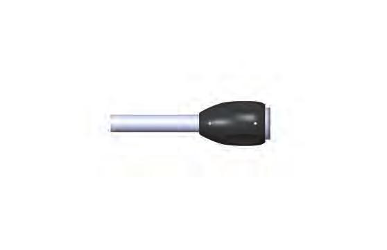
8 Minimally Invasive Spinal System Gray Ø4.5mm Tap Blue Ø Tap Ø Gold Ø Tap Green Tap Distractor Tips Compressor Tips Compression/Distraction Cuffs Compressor Tips, Wide Rod Pusher Ratcheting Handle, T-handle, 1/4 sq 5


9 IMPLANTS AND INSTRUMENTATION Ancillary Driver Calipers Blunt Dissector MIS Distractor MIS Compressor Rod Holder Torque Limiting Handle Dilator #1, Stainless Steel Dilator #2, Stainless Steel Dilator #3, Stainless Steel Dilator #4, Non-Conductive Dilator #5, Non-Conductive Straight Ratcheting Handle Nitinol Guidewire 6
10 Minimally Invasive Spinal System Surgical Technique 1. Preparation and Exposure Preoperative planning is critical in the preparation for spinal surgery. A complete radiographic evaluation (A/P and lateral films) of the patient should be completed for proper diagnosis prior to surgery. Carefully place the patient in the prone position in normal lordosis following induction of anesthesia. 2. Access Needle and K-wire Insertion Create an incision slightly larger than the outer diameter of the radiolucent sleeve, approximately 18mm. Using fluoroscopy, insert the Access Needle Stylet and Access Needle Sheath into the pedicle. Remove the stylet and insert the K-wire through the Access Needle Sheath. Confirm the position of the K-wire with A/P and lateral views. Once the K-wire position is determined, remove only the Access Needle Sheath. 7
11 SURGICAL TECHNIQUE 3. Awl Advance Dilators #1-3 over the K-wire until the distal tip of the Dilators contact the pedicle. Remove Dilators #1 and #2 and insert the Bone Awl over the K-wire and through Dilator #3 to penetrate the cortex. 4. Tap Remove the Bone Awl and insert the radiolucent Dilator #4 over Dilator #3. Remove Dilators #1-3. The radiolucent Dilator #4 assists with increased visualization under fluoroscopy and nerve monitoring. Securely attach the Ratcheting Handle to the cannulated Tap. Pass the Tap over the K-wire and through Dilator #4. Utilizing fluoroscopy to ensure that the K-wire does not advance, tap to the desired depth. Confirm depth measurement on the Tap against the top of Dilator #4 and select the appropriate screw length. NOTE: The thread length at the distal end of the tap is measured at 25mm. 8

12 Minimally Invasive Spinal System 5. Screw Impant Once tapping is complete, remove the Tap and insert the radiolucent Dilator #5 over Dilator #4. Remove Dilator #4. Securely attach the Ratcheting Handle to the Screwdriver. Securely align the Screwdriver tip with the saddle and hex of the polyaxial screw. Rotate the proximal knob on the Screwdriver clockwise to secure the polyaxial screw to the Screwdriver. Utilizing fluoroscopy, insert the polyaxial screw over the K-wire to the appropriate depth. The K-wire should be removed as soon as the polyaxial screw is advanced into the pedicle to the desired depth. Once the screw is inserted, turn the proximal knob on the Screwdriver counter-clockwise and remove the Screwdriver from the screw. Place remaining screws using the same technique. NOTE: Always have visibility of K-wire. When removing the Tap, retrieve tap until threads are out of bone, detach and remove Ratcheting Handle, then carefully remove the Tap with the assist of a K-wire. 9


13 SURGICAL TECHNIQUE 6. Rod Measuring Insert one arm of the rod measuring Caliper into each of the outermost extended tabs until each leg is fully seated in the polyaxial screw head. Check placement via fluoroscopy. Once correctly positioned, read the rod length measurement indicated at the top of the Caliper. NOTE: When the arrow on the Caliper is between two numbers, (i.e. 65mm 75mm), always choose the longer rod length.. 7. Rod Insertion Turn the knob on the Rod Inserter counter clockwise and attach the selected rod at the distal end. Turn the knob on the Rod Inserter clockwise to secure the rod. If required, use the Initial Cap Tightener to engage and turn the knob to secure the rod. 8. Locking Cap Insertion Securely engage the Locking Cap onto the Initial Locking Cap Tightener. While holding the rod in position with the Rod Inserter, advance the Initial Locking Cap Tightener through the extended tabs and rotate clockwise to seat the Locking Cap and secure the rod in place. It is imperative that the connection feature and bulleted profile at the ends of the rod are located outside of the tulip head to ensure the appropriate screw/rod interface is established. Confirm rod position fluoroscopically with A/P and lateral views. Place remaining Locking Caps using the same technique. 10


14 Minimally Invasive Spinal System 9. Final Tightening Option 1 Slide the CT/Tower Breaker over the extended tabs of the screws. Secure the Locking Cap onto the Locking Cap Driver and insert it through the extended tabs. Attach the Torque Limiting Handle and apply a clockwise torque of 80 in-lbs. to secure the construct (an audible and tactile confirmation will alert the user that 80 in-lbs is achieved). Perform final tightening on all the Locking Caps using the same technique. Start = Initial engagement between Locking Cap and internal threads End = The Locking Cap is fully advanced and rod is seated on the tulip head. The Blue Collar will assist in identifying the initial engagement of the Locking Cap with internal threads of tulip head and confirm rod is fully seated Option 2 While pressing the button on the Torque Handle, securely attach it to the Counter Torque Wrench. Slide the Counter Torque Wrench over the extended tabs of the screws. Secure the Locking Cap onto the Locking Cap Driver and insert it through the extended tabs. Attach the Torque Limiting Handle and apply a clockwise torque of 80 in-lbs. to secure the construct (an audible and tactile confirmation will alert the user that 80 in-lbs is achieved). Perform final tightening on all the Locking Caps using the same technique. Note: Using fluoroscopy, verify that the rod overhangs the outermost screws by the bulleted profile at one end and full visualization of the circle of the connection feature at the other end. Press button and hold during attachment to the shaft 11
15 SURGICAL TECHNIQUE 10. Reduction The screw allows 10mm of rod reduction while the Reducer accommodates up to 20mm of additional rod reduction. Internal threads within the tabs promote additional reduction capability. Securely engage the Locking Cap onto the Rod Reducer. While holding the rod in position with the Rod Inserter, advance the Rod Reducer through the extended tabs and rotate clockwise to reduce the rod into the saddle of the screw. Continue to advance the Rod Reducer to seat the Locking Cap and secure the rod in place. Option 1 Once reduction is achieved, the Rod Reducer can be utilized to apply 80 in-lbs. torque and secure the construct. Remove the handle (black) from the Rod Reducer and slide the CT/Tower Breaker over the extended tabs of the screws. Attach a Torque Limiting Handle (orange) on the Rod Reducer. While holding the CT/Tower Breaker in place, turn the Torque Limiting Handle clockwise until 80 in-lbs. torque is achieved (an audible and tactile confirmation will alert the user that 80 in-lbs. is achieved). Option 2 Once reduction is achieved, the Rod Reducer can be utilized to apply 80 in-lbs. torque and secure the construct. Remove the handle (black) from the Rod Reducer and slide the Counter Torque Wrench over the extended tabs of the screws. Attach a Torque Limiting Handle (orange) on the Rod Reducer. While holding the Counter Torque in place, turn the Torque Limiting Handle clockwise until 80 in-lbs. torque is achieved (an audible and tactile confirmation will alert the user that 80 in-lbs. is achieved). 12
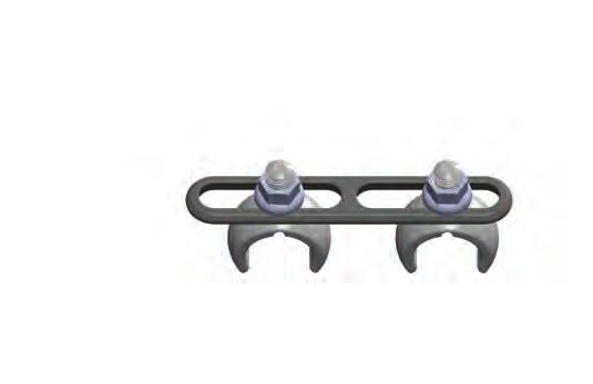
16 Minimally Invasive Spinal System Surgical Technique Guide 11.Compression/Distraction Prior to compression/distraction, perform final tightening to secure one of the constructs at the outermost polyaxial screws. Press and hold the button on each Compression/Distraction Cuff and slide over the Counter Torque Wrenches. Release the buttons and assure the Compression/Distraction Cuffs are attached to the Counter Torque Wrenches. Simply finger tighten the top bolt and loosen the bottom bolt of the Compression/Distraction Cuffs. Attach the Compressor/Distractor to the Counter Torque Wrenches. Apply desired compression or distraction. Perform final tightening on the 2nd polyaxial screw construct. Note: Distractor tips can be used with compressor for closer constructs. Compression/Distraction can be done without cuffs. 12. Tab Removal Option 1 Upon final tightening of the locking cap, the CT/Tower Breaker can be used to break off the extended tab of the screw. While holding onto the Torque Handle, turn the CT/Tower Breaker counter-clockwise to break off the extended tab of the screw. Option 2 With the Counter Torque Wrench seated over the extended tabs and the rod, insert the Extension Tab Remover through the screws. Once inserted completely, turn the Remover clockwise until it engages the slots of the screw tabs. This is confirmed with tactile feedback. Continue turning the Remover clockwise and applying torque until tabs have separated from the screw. 13

17 SURGICAL TECHNIQUE Final Construct Lateral View of the Final Construct A/P View of the Final Construct 13. Removal If revision is required, remove the Locking Cap from the saddle of the screw using the Counter Torque Wrench, T-Handle and Locking Cap Driver. Ensure the Locking Cap Driver is fully seated in the Locking Cap. Apply downward pressure and rotate the T-Handle counter clockwise until the Locking Cap is completely unthreaded. Repeat for all the screws and remove the rod. Securely insert the Ancillary Driver to the screw and turn counter clockwise to remove the screw. 14
18 14. Any case not described in the Indications. 15. Any patient unwilling to cooperate with the post-operative instructions. 16. Any time implant utilization would interfere with anatomical structures or expected physiological performance Patents Pending All Rights Reserved Confidential LIFE SPINE Extended Tab MIS System Standard Product Insert Life Spine Tel: S. Quality Dr. Fax: Huntley, IL USA Important Information on the Extended Tab MIS System Purpose: The Extended Tab MIS System consists of screws, longitudinal rods, and cross connectors intended to provide temporary stabilization and immobilization following surgery to fuse a portion of the thoracic, lumbar, and/or sacral spine. Description: The Extended Tab MIS System consists of an assortment of rods, screws, and cross connectors. The bone screw, head, and taper lock are assembled together during manufacturing to create the Extended Tab MIS System screw assembly component. The cross connectors are also assembled during manufacturing. The Extended Tab MIS System implant components are made from titanium alloy (Ti-6Al-4V ELI) as described by ASTM F136.Do not use any of the Extended Tab MIS System components with the components from any other system or manufacturer. Indications, Contraindications, and Possible Adverse Effects. Indications: Internal fixation implants are load-sharing devices intended to stabilize and maintain alignment until normal healing occurs. Implants are not intended to replace normal body structures or bear the weight of the body in the presence of incomplete bone healing. The Extended Tab MIS System, when properly used, is intended for posterior pedicle screw fixation of the non-cervical posterior spine in skeletally mature patients. It provides stabilization and immobilization of spinal segments as an adjunct to fusion. When used as a posterior spine thoracic/lumbar system, the Extended Tab MIS System is indicated for one or more of the following: (1) degenerative disc disease (is defined as back pain of discogenic origin with degeneration of the disc confirmed by history and radiographic studies), (2) trauma (i.e. fracture or dislocation), (3) curvatures (scoliosis, kyphosis, and/or lordosis), (4) spinal tumor, (5) failed previous fusion (6) pseudarthrosis, (7) spinal stenosis, (8) spondylolisthesis. Contraindications: Contraindications include, but are not limited to: 1. Infection, local to the operative site. 2. Signs of local inflammation. 3. Fever or leukocytosis. 4. Morbid obesity. 5. Pregnancy. 6. Mental illness, alcoholism, drug abuse. 7. Any medical or surgical condition which would preclude the potential benefit of spinal implant surgery, such as the elevation of sedimentation rate unexplained by other diseases, elevation of white blood count (WBC), or a marked left shift in the WBC differential count. 8. Rapid joint disease, bone absorption, osteopenia, and/or osteoporosis. Osteoporosis is a relative contraindication since this condition may limit the degree of obtainable correction, the amount of mechanical fixation, and/or the quality of the bone graft. 9. Suspected or documented metal allergy or intolerance. 10. Any case not needing a bone graft and fusion or where fracture healing is not required. 11. Any case requiring the mixing of metals from different components. 12. Any patient having inadequate tissue coverage over the operative site or where there is inadequate bone stock, bone quality, or anatomical definition. 13. Any condition that totally precludes the possibility of fusion, i.e. cancer, kidney dialysis Potential Adverse Events: A listing of possible adverse events includes, but is not limited to: 1. Early or late loosening of any or all of the components. 2. Disassembly, bending, and/or breakage of any or all of the components. 3. Foreign body (allergic) reaction to implants, debris, corrosion products, graft material, including metallosis, staining, tumor formation, and/or auto-immune disease. 4. Pressure on the skin from component parts in patients with inadequate tissue coverage over the implant possibly causing skin penetration, irritation, and/or pain. Bursitis. Tissue damage caused by improper positioning and placement of implants or instruments. 5. Post-operative change in spinal curvature, loss of correction, height, and/or reduction. 6. Infection. 7. Dural tears. 8. Loss of neurological function, including paralysis (complete or incomplete), dysesthesias, hyperesthesia, anesthesia, paraesthesia, appearance of radiculopathy, and/or the development or continuation of pain, numbness, neuroma, or tingling sensation. 9. Neuropathy, neurological deficits (transient or permanent), bilateral paraplegia, reflex deficits, and/or arachnoiditis. 10. Loss of bowel and/or bladder control or other types of urological system compromise. 11. Scar formation possibly causing neurological compromise around nerves and/or pain. 12. Fracture, microfracture, resorption, damage, or penetration of any spinal bone and/or bone graft or bone graft harvest site at, above, and/or below the level of surgery. 13. Herniated nucleus pulposus, disc disruption, or degeneration at, above, or below the level of surgery 14. Interference with radiographic, CT, and/or MR imaging because of the presence of the implants. 15. Graft donor site complications including pain, fracture, or wound healing problems. 16. Atelectasis, ileus, gastritis, herniated nucleus pulposus, retropulsed graft. 17. Hemorrhage, hematoma, seroma, embolism, edema, stroke, excessive bleeding, phlebitis, wound necrosis, wound dehiscence, or damage to blood vessels. 18. Gastrointestinal and/or reproductive system compromise, including sterility and loss of consortium. 19. Development of respiratory problems, e.g. pulmonary embolism, bronchitis, pneumonia, etc. 20. Change in mental status 21. Non-union (or pseudarthrosis). Delayed union. Mal-union. 22. Cessation of any potential growth of the operated portion of the spine. Loss of spinal mobility or function. 23. Inability to perform the activities of daily living. 24. Paralysis 25. Death Note: Additional surgery may be necessary to correct some of these anticipated adverse events Warnings and Precautions: The Extended Tab MIS System has not been evaluated for safety and compatibility in the MR environment. The Extended Tab MIS System has not been tested for heating or migration in the MR environment. A successful result is not always achieved in every surgical case. This fact is especially true in spinal surgery where many extenuating circumstances may compromise the results. The Extended Tab MIS System is only a temporary implant used for the correction and stabilization of the spine. This system is intended to be used to augment the development of a spinal fusion by providing temporary stabilization. This device system is not intended to be the sole means of spinal support. Bone grafting must be part of the spinal fusion procedure in which the Extended Tab MIS System is utilized. Use of this product without a bone graft or in cases that develop into a non-union will not be successful. This spinal implant cannot withstand body loads without the support of bone. In this event, bending, loosening, disassembly and/or breakage of the device(s) will eventually occur. Preoperative planning and operating procedures, including knowledge of surgical techniques, proper reduction, and proper selection and placement of the implant are important considerations in the successful utilization of the Extended Tab MIS System by the surgeon. Further, the proper selection and compliance of the patient will greatly affect the results. Patients who smoke have been shown to have an increased incidence of non-unions. These patients should be advised of this fact and warned of this consequence. Obese, malnourished, and/or alcohol and/or other drug abuse patients are also not good candidates for spine fusion. Patients with poor muscle and bone quality and/or nerve paralysis are also not good candidates for spine fusion. WARNING: The implantation of pedicle screw spinal systems should be performed only by experienced spinal surgeons with specific training in the use of this pedicle screw spinal system because this is a technically demanding procedure presenting a risk of serious injury to the patient. WARNING: The safety and effectiveness of pedicle screw spinal systems have been established only for spinal conditions with significant mechanical instability or deformity requiring fusion with instrumentation. These conditions are significant mechanical instability or deformity of the thoracic, lumbar, and sacral spine secondary to severe spondylolisthesis with objective evidence of neurologic impairment, fracture, dislocation, scoliosis, kyphosis, spinal tumor, and failed previous fusion (pseudarthrosis). The safety and effectiveness of these devices for any other conditions are unknown. PHYSICIAN NOTE: Although the physician is the learned intermediary between the company and the patient, the indications, contraindications, warnings and precautions given in this document must be conveyed to the patient. CAUTION: FOR USE ON OR BY THE ORDER OF A PHYSICIAN ONLY. CAUTION: FEDERAL LAW (USA) RESTRICTS THESE DEVICES TO SALE BY OR ON THE ORDER OF A PHYSICIAN. Other preoperative, intraoperative, and postoperative warnings are as follows: Implant Selection: The selection of the proper size, shape and design of the implant for each patient is crucial to the success of the procedure. Metallic surgical implants are subject to repeated stresses in use, and their strength is limited by the need to adapt the design to the size and shape of human bones. Unless great care is taken in patient selection, proper placement of the implant, and postoperative management to minimize stresses on the implant, such stresses may cause metal fatigue and consequent breakage, bending or loosening of the device before the healing process is complete, which may result in further injury or the need to remove the device prematurely. PI-0003-E PI-0003-E 15

19 Preoperative: 1. Only patients that meet the criteria described in the indications should be selected. 2. Patient conditions and/or predispositions such as those addressed in the aforementioned contraindications should be avoided. 3. Care should be used in the handling and storage of the implant components. The implants should not be scratched or otherwise damaged. Implants and instruments should be protected during storage especially from corrosive environments. 4. The type of construct to be assembled for the case should be determined prior to beginning the surgery. An adequate inventory of implant sizes should be available at the time of surgery, including sizes larger and smaller than those expected to be used. 5. Since mechanical parts are involved, the surgeon should be familiar with the various components before using the equipment and should personally assemble the devices to verify that all parts and necessary instruments are present before the surgery begins. The Extended Tab MIS System components are not to be combined with the components from another manufacturer. Different metal types should not be used together. 6. All components and instruments should be cleaned and sterilized before use. Additional sterile components should be available in case of an unexpected need. Intraoperative: 1. Any instruction manuals should be carefully followed. 2. At all times, extreme caution should be used around the spinal cord and nerve roots. Damage to nerves will cause loss of neurological functions. 3. When the configuration of the bone cannot be fitted with an available temporary internal fixation device, and contouring is absolutely necessary, it is recommended that such contouring be gradual and great care be used to avoid notching or scratching the surface of the device(s). The components should not be repeatedly or excessively bent any more than absolutely necessary. The components should not be reverse bent at the same location. 4. The implant surfaces should not be scratched or notched, since such actions may reduce the functional strength of the construct. 5. Bone grafts must be placed in the area to be fused and the graft must be extended from the upper to the lower vertebrae to be fused. 6. Bone cement should not be used since this material will make removal of the components difficult or impossible. The heat generated from the curing process may also cause neurological damage and bone necrosis. 7. Recheck the tightness of all screws after finishing ensuring that none have loosened during the tightening of the other screws. Caution: Excessive torque on the threads may cause the threads to strip in the bone, reducing fixation. 8. Breakage, slippage, or misuse of the instruments or implant components may cause injury to the patient or the operative personnel. 9. Extreme caution should be used around the spinal cord and nerve roots. Damage to the nerves will cause loss of neurological functions. 10. To insert a screw properly, a guide wire should first be used, followed by a sharp tap. 11. Do not overtap or use a screw/bolt that is either too long or too large. Overtapping or using an incorrectly sized screw/bolt may cause nerve damage, hemorrhage, or the other possible adverse events listed elsewhere in this package insert. If screw/bolts are being inserted into spinal pedicles, use as large a screw/bolt diameter as will fit into each pedicle. 12. To assume maximum stability, two or more crosslink plates on two bilaterally placed, continuous rods should be used whenever possible. Postoperative: The physician's postoperative directions and warnings to the patient and the corresponding patient compliance are extremely important. 1. Detailed instructions on the use and limitations of the device should be given to the patient. If partial weight-bearing is recommended or required prior to firm bony union, the patient must be warned that bending, loosening or breakage of the components are complications which can occur as a result of excessive or early weight-bearing or excessive muscular activity. The risk of bending, loosening, or breakage of a temporary internal fixation device during postoperative rehabilitation may be increased if the patient is active, or if the patient is debilitated, demented or otherwise unable to use crutches or other such weight supporting devices. The patient should be warned to avoid falls or sudden jolts in spinal position. 2. To allow the maximum chances for a successful surgical result: the patient or device should not be exposed to mechanical vibrations that may loosen the device construct. The patient should be warned of this possibility and instructed to limit and restrict physical activities, especially lifting and twisting motions and any type of sport participation. The patient should be advised not to smoke or consume alcohol during the bone graft healing process. 3. The patient should be advised of their inability to bend at the point of spinal fusion and taught to compensate for this permanent physical restriction in body motion. 4. If a non-union develops or if the components loosen, bend, and/or break, the device(s) should be revised and/or removed immediately before serious injury occurs. Failure to immobilize a delayed or non-union of bone will result in excessive and repeated stresses on the implant. By the mechanism of fatigue these stresses can cause eventual bending, loosening, or breakage of the device(s). It is important that immobilization of the spinal surgical site be maintained until firm bony union is established and confirmed by roentgenographic examination. The patient must be adequately warned of these hazards and closely supervised to insure cooperation until bony union is confirmed. 5. The Extended Tab MIS System implants are temporary internal fixation devices. Internal fixation devices are designed to stabilize the operative site during the normal healing process. After the spine is fused, these devices serve no functional purpose and should be removed. In most patients removal is indicated because the implants are not intended to transfer or support forces developed during normal activities. If the device is not removed following completion of its intended use, one or more of the following complications may occur: (1) Corrosion, with localized tissue reaction or pain, (2) Migration of implant position possibly resulting in injury, (3) Risk of additional injury from postoperative trauma, (4) Bending, loosening and/or breakage, which could make removal impractical or difficult, (5) Pain, discomfort, or abnormal sensations due to the presence of the device, (6) Possible increased risk of infection, and (7) Bone loss due to stress shielding. While the surgeon must make the final decision on implant removal, it is the position of the Orthopedic Surgical Manufacturers Association that whenever possible and practical for the individual patient, bone fixation devices should be removed once their service as an aid to healing is accomplished, particularly in younger and more active patients. Any decision to remove the device should take into consideration the potential risk to the patient of a second surgical procedure and the difficulty of removal. Implant removal, should be followed by adequate postoperative management to avoid fracture. 6. Any retrieved devices should be treated in such a manner that reuse in another surgical procedure is not possible. As with all orthopedic implants, none of the Extended Tab MIS System components should ever be reused under any circumstances. Cleaning and Decontamination: Precleaning: Remove debris from instruments with sterile water and sponge during the procedure to prevent drying of blood and bodily fluids. Blood and bodily fluids are highly corrosive and can produce stains that are difficult to remove. Cleaning: All instruments and trays must first be cleaned before sterilization and introduction into a sterile surgical field. Immediately after the procedure, place the instruments in a tray and cover with a towel moistened with sterile water and transport to decontamination environment. A room temperature enzymatic cleaner bath (soak) or a solution of room temperature water and neutral ph detergent are effective in removing organic material from instruments. Use distilled (demineralized) water if possible. Instruments should be fully submerged for at least 10 minutes. Instruments and trays must be thoroughly cleaned. Be sure dissimilar metal instruments are separated. Immerse instruments fully opened and flush all cannulas with room temperature water until rinse water runs clear. Use a small brush to remove soil from all surfaces of the instrument while fully immersed in the solution. Remove soil from hinges, jaws, tips, box locks, and ratchets. Never use steel wool, wire brushes, or highly abrasive detergents or cleaners to remove soil from instruments and trays. If there is any visual contamination, repeat the steps as necessary until the instruments and trays are visually clean. Rinse instruments and trays under running room temperature water for at least 1 minute to remove solutions. If contamination is unable to be removed, return the instrument and/or tray to Life Spine in a sealed container clearly marked contaminated. Instruments and trays should never be exposed to cleaning agents containing any peroxides. Note: Certain cleaning solutions such as those containing caustic soda, formalin, glutaraldehyde, bleach and/or other alkaline cleaners may damage some devices, particularly instruments; these solutions should not be used. All products should be treated with care. Improper use or handling may lead to damage and possible improper functioning of the device. Sterilization: Unless noted otherwise on the package labeling, the Extended Tab MIS System components are provided non-sterile. These products need to be steam sterilized by the hospital using the following method: Method Cycle Temperature Exposure Time Dry Time Steam Gravity Displacement 270 F(132 C) 30 minutes 60 minutes Method Cycle Temperature Exposure Time Dry Time Steam Prevacuum 270 F(132 C) 4 minutes 60 minutes The Sterility Assurance Level (SAL) is 1 x 10⁻⁶, via the indicated methods. No claims of pyrogenicity are made. Remove all packaging materials prior to sterilization. Do not stack trays during sterilization. Use only sterile products in the operative field. Always immediately re-sterilize all implants, instruments, and trays used in surgery. This process must be performed before handling or (if applicable) returning to Life Spine. This gravity displacement sterilization cycle is not considered by the Food and Drug Administration to be a standard sterilization cycle. It is the end user s responsibility to use only sterilizers and accessories (such as sterilization wraps, sterilization pouches, chemical indicators, biological indicators, and sterilization cassettes) that have been cleared by the Food and Drug Administration for the selected sterilization cycle specifications (time and temperature). Product Complaints: Any Health Care Professional (e.g., customer or user of this system of products), who has any complaints or who has experienced any dissatisfaction in the product quality, identity, durability, reliability, safety, effectiveness and/or performance, should notify the distributor, LIFE SPINE. Further, if any of the implanted Extended Tab MIS System component(s) ever "malfunctions", (i.e., does not meet any of its performance specifications or otherwise does not perform as intended), or is suspected of doing so, the distributor should be notified immediately. If any LIFE SPINE product ever "malfunctions" and may have caused or contributed to the death or serious injury of a patient, the distributor should be notified immediately by telephone, fax or written correspondence. When filing a complaint, please provide the component(s) name and number, lot number(s), your name and address, the nature of the complaint and notification of whether a written report from the distributor is requested. Further Information: Recommended directions for use of this system (surgical operative techniques) are available at no charge upon request. If further information is needed or required, please contact: Life Spine, Inc. Tel: S. Quality Dr. Fax: Huntley, IL USA The Extended Tab MIS System is a trademark of Life Spine. Patents Pending. Packaging: Packages for each of the components should be intact upon receipt. If a loaner or consignment system is used, all sets should be carefully checked for completeness and all components should be carefully checked for lack of damage prior to use. Damaged packages or products should not be used, and should be returned to LIFE SPINE. PI-0003-E PI-0003-E 16
20 Life Spine S. Quality Drive Huntley, IL Phone (847) Fax (847) w w w. l i f e s p i n e. c o m Copyright 2014 by Life Spine Inc. Products referenced with are registered trademarks of Life Spine. U.S. & Foreign U.S. Patents & Foreign Pending Patents Pending Doc. No. STG Doc. No. Rev. STG C Rev. C
BONE GRAFT WASHER _Rev A IMPORTANT INFORMATION ON THE BONE GRAFT WASHER
 0381080_Rev A BONE GRAFT WASHER IMPORTANT INFORMATION ON THE BONE GRAFT WASHER 03/2008 Medtronic Sofamor Danek USA, Inc. 1800 Pyramid Place Memphis, Tennessee 38132 Telephone: 800-933-2625 (in U.S.A.)
nvt Transforaminal Lumbar Interbody Fusion System
 nvt Transforaminal Lumbar Interbody Fusion System 1 IMPORTANT INFORMATION FOR PHYSICIANS, SURGEONS, AND/OR STAFF The nv a, nv p, and nv t are an intervertebral body fusion device used in the lumbar spine
nvp Posterior Lumbar Interbody Fusion System
 nvp Posterior Lumbar Interbody Fusion System 1 IMPORTANT INFORMATION FOR PHYSICIANS, SURGEONS, AND/OR STAFF The nv a, nv p, and nv t are an intervertebral body fusion device used in the lumbar spine following
nva Anterior Lumbar Interbody Fusion System
 nva Anterior Lumbar Interbody Fusion System 1 IMPORTANT INFORMATION FOR PHYSICIANS, SURGEONS, AND/OR STAFF The nv a, nv p, and nv t are an intervertebral body fusion device used in the lumbar spine following
LBL-014. Rev
 Package Insert Z- CLAMP ISP System Device Description: The Z-CLAMP ISP System is supplemental fixation device consisting of a variety of shapes and sizes of one-level lumbar and sacral plates and screws.
A U X I L I A R Y C O N N E C T O R S Surgical Technique
 A U X I L I A R Y C O N N E C T O R S Surgical Technique AUXILIARY CONNECTORS ISSYS LP Auxiliary Connectors The ISSYS LP auxiliary connectors were designed to provide medial-lateral variability for the
TM TM Surgical Technique
 TM TM Surgical Technique TABLE OF CONTENTS Reli SP Spinous Plating System Overview Device Description Implant Features Indications Instruments Access Instruments Preparation Instruments Insertion Instruments
NEO PEDICLE SCREW SYSTEM V. 2.0
 NEO PEDICLE SCREW SYSTEM 2017-08 V. 2.0 Neo Medical S.A. Route de Lausanne 157A 1096 Villette Switzerland 1250 Important Information on the NEO PEDICLE SCREW SYSTEM CAUTION: USA law restricts this device
Thunderbolt. surgical technique. MIS Pedicle Screw System. Where Nimble and Secure Intersect
 Thunderbolt TM MIS Pedicle Screw System Where Nimble and Secure Intersect surgical technique i www.choicespine.com System Features Dovetail set screw: Minimizes head splay and cross-threading Secure connection
ACP1 CERVICAL PLATE SPINAL SYSTEM SURGICAL TECHNIQUE GUIDE II.
 I. ACP1 CERVICAL PLATE II. SPINAL SYSTEM SURGICAL TECHNIQUE GUIDE I. Introduction The Gold Standard Orthopaedics, LLC ACP1 Spinal System was designed with surgeons to incorporate strength, functionality,
INTELLIGENT SPINAL SYSTEM
 INTELLIGENT SPINAL SYSTEM I. Introduction II. Product Specification III. Surgical Technique IV. Ordering Information V. IFU for Lospa IS SPINAL SYSTEM The LOSPA IS spinal system consists of
HydraLok. Operative Technique. Polyaxial Pedicle Screw System
 HydraLok Operative Technique Polyaxial Pedicle Screw System Table of Contents Introduction...1 OPERATIVE TECHNIQUE OVERVIEW...2 DETAILED OPERATIVE TECHNIQUE...4 LOCATE AND PREPARE THE PEDICLE...4 PROBE
X-spine Systems, Inc. Butrex Lumbar Buttress Plating System
 X-spine Systems, Inc. Butrex Lumbar Buttress Plating System GENERAL DESCRIPTION The Butrex Lumbar Buttress Plating System is intended for anterior screw fixation to the L1 to S1 spine. The Butrex System
X-spine Systems, Inc. Spider Cervical Plating System
 X-spine Systems, Inc. Spider Cervical Plating System GENERAL DESCRIPTION The Spider Cervical Plating System consists of screws and plates offered in various sizes so that adaptations can be made to take
X-spine Aranax Anterior Cervical Plating System Instructions for Use / Package Insert
 X-spine Aranax Anterior Cervical Plating System Instructions for Use / Package Insert GENERAL INFORMATION The Aranax Cervical Plating System consists of screws and plates offered in various sizes so that
Spartan S 3 Facet Screw System PACKAGE INSERT
 LB-004 Rev 6 Spartan S 3 Facet Screw System PACKAGE INSERT CAUTION: Federal law (USA) restricts these devices to sale by or on the order of a physician. Implants and disposable instruments single use only.
Y o u r Id e a s En g i n e e r e d t o Li f e
 ISSYS LP Spinal Fixation System Surgical Guide Y o u r Id e a s En g i n e e r e d t o Li f e In t r o d u c t i o n ISSYS LP Sp i n a l Fixation System The foundation of the ISSYS LP Spinal Fixation System
Thoracolumbar Spinal System NAUTILUS SURGICAL TECHNIQUE GUIDE
 NAUTILUS SURGICAL TECHNIQUE GUIDE NAUTILUS CONTENTS Introduction 1 1 Implants 3 Instruments 6 Surgical Technique 10 Product Information 17 NAUTILUS NAUTILUS Thoracolumbar Spinal System The NAUTILUS Thoracolumbar
VTI INTERLINK PEDICLE SCREW SYSTEM
 VTI INTERLINK PEDICLE SCREW SYSTEM SURGICAL TECHNIQUE FORWARD THINKING FOR THE BACK. DEVICE DESCRIPTION The VTI InterLink Pedicle Screw System is comprised of polyaxial pedicle screws in various diameters
Table of Contents.
 surgical technique The Ambassador TM Anterior Cervical Plate System is a versatile system of implants and instruments with a variety of sizes to provide optimal anatomic compatibility. The integrated cam
Threshold Pedicular Fixation System Surgical Technique
 Threshold Pedicular Fixation System Surgical Technique Table of Contents Patient Preparation and Positioning... 2 Determining Incision Location... 3 Assembling the Cannulated Awl... 4 Guide Wire Placement...
X-spine Systems, Inc. Axle Interspinous Fusion System
 X-spine Systems, Inc. Axle Interspinous Fusion System GENERAL INFORMATION The Axle Interspinous Fusion System of X-spine Systems, Inc., is an internal fixation device for spinal surgery. Various sizes
OPERATIVE TECHNIQUE. anterior cervical plating system
 OPERATIVE TECHNIQUE 3º anterior cervical plating system Introduction 1 Pre-Operative Technique 2 Oerative Technique 3 Instructions for Use 12 Part Numbers 16 The surgical technique shown is for illustrative
Valencia Pedicle Screw Surgical Technique
 Valencia Pedicle Screw Surgical Technique VALENCIA CIRCUIT TABLE OF CONTENTS Design Rationale Indications for Use Surgical Technique 1. Pedicle Preparation 2. Screw Insertion 3. Rod Placement 4. Locking
TiLock XT Minimally Invasive Surgery (MIS) Pedicle Screw System
 Pedicle Screw System") TiLock XT Minimally Invasive Surgery (MIS) Pedicle Screw System The Genesys Spine TiLock XT Minimally Invasive Surgery (MIS) Pedicle Screw System consists of rods (straight and curved), lock screws, and
TiLock XT Minimally Invasive Surgery (MIS) Pedicle Screw System The Genesys Spine TiLock XT Minimally Invasive Surgery (MIS) Pedicle Screw System consists of rods (straight and curved), lock screws, and
TiLock 2 Spinal System. Surgical Technique
 TiLock 2 Spinal System Surgical Technique Table of Contents Page Preoperative Planning 4 Pedicle Preparation 5 Probe 5 Tap Pedicle 6 Screw Options 7 Screw Insertion 8 Aligning the Windows 9 Rod Insertion
3 Operative Technique U.S. EDITION
 3 A N T E R I O R C E R V I C A L P L AT E S Y S T E M 3 Operative Technique U.S. EDITION Table of Contents 1 INTRODUCTION 2 PRE-OPERATIVE 3 OPERATIVE 12 INSTRUCTIONS FOR USE 16 PART NUMBERS Orthofix Spinal
X-spine Systems, Inc. Silex Sacroiliac Joint Fusion System
 X-spine Systems, Inc. Silex Sacroiliac Joint Fusion System GENERAL INFORMATION The Silex Sacroiliac Joint Fusion System consists of different diameter bone screws in various lengths and thread configurations
X-spine Systems, Inc. Xpress Minimally Invasive Pedicle Screw System
 X-spine Systems, Inc. Xpress Minimally Invasive Pedicle Screw System GENERAL INFORMATION The Xpress Minimally Invasive Pedicle Screw System consists of rods, pedicle screws, screw caps and hand instruments.
TiLock XT Minimally Invasive Surgery (MIS) Pedicle Screw System
 Pedicle Screw System") Minimally Invasive Surgery (MIS) Pedicle Screw System Surgical Technique Guide 2 Minimally Invasive Surgery (MIS) Pedicle Screw System The Genesys Spine Minimally Invasive Surgery (MIS) Pedicle Screw System
Minimally Invasive Surgery (MIS) Pedicle Screw System Surgical Technique Guide 2 Minimally Invasive Surgery (MIS) Pedicle Screw System The Genesys Spine Minimally Invasive Surgery (MIS) Pedicle Screw System
Cervical Screw System
 Cervical Screw System LnK Posterior Cervical Screw The LnK Cervical Fixation System provides a top-loading, simple and secure system for rigid fixation. The LnK Cervical Fixation system includes instrumentation
Alamo C. Cervical Interbody System Surgical Technique. An Alliance Partners Company
 Cervical Interbody System Surgical Technique Table of Contents Indications for Use................................1 Device Description............................... 1 Alamo C Instruments..............................
Zimmer Anterior Buttress Plate System. Surgical Technique
 Zimmer Anterior Buttress Plate System Surgical Technique 2 Zimmer Anterior Buttress Plate System Surgical Technique Zimmer Anterior Buttress Plate System Surgical Technique Description, Indications & Contraindications...
X-spine Systems, Inc. Calix PC Spinal Implant System
 X-spine Systems, Inc. Calix PC Spinal Implant System Y IMPORTANT NOTE: The user acknowledges that he/she has read and agreed to the conditions in this insert, which are to be considered as contractual.
Pinit Plate Small Bone Fusion System Bone Plate & Screw System
 Pinit Plate Small Bone Fusion System Bone Plate & Screw System Description The Pinit Plate Small Bone Fusion System consists of 2-hole bone plates made available in three length options and two thickness
Royal Oak Cervical Plate System
 Royal Oak Cervical Plate System Manufactured by Nexxt Spine, Inc. Royal Oak Cervical Plate System INTRODUCTION FEATURES AND BENEFITS Table of Contents SURGICAL TECHNIQUE Step 1. Patient Positioning Step
ASFORA ANTERIOR CERVICAL PLATE SYSTEM (AACP) SURGICAL PROCEDURE MANUAL
 SURGICAL PROCEDURE MANUAL") ASFORA ANTERIOR CERVICAL PLATE SYSTEM (AACP) SURGICAL PROCEDURE MANUAL Contents: Introduction Indications Contraindications Warnings Precautions Implant Overview Instruments Overview Surgical Technique
ASFORA ANTERIOR CERVICAL PLATE SYSTEM (AACP) SURGICAL PROCEDURE MANUAL Contents: Introduction Indications Contraindications Warnings Precautions Implant Overview Instruments Overview Surgical Technique
X-spine Systems, Inc. Fixcet Spinal Facet Screw System
 X-spine Systems, Inc. Fixcet Spinal Facet Screw System GENERAL INFORMATION The Fixcet Spinal Facet Screw System is designed to provide bilateral, transfacet fixation of the spinal facet joint in the lumbar
TABLE OF CONTENTS. ShurFit Anterior Cervical Interbody Fusion (ACIF) System Overview 2. Implant Specifications 3. Instrument Features 4
 System Overview 2. Implant Specifications 3. Instrument Features 4") Surgical Technique TABLE OF CONTENTS ShurFit Anterior Cervical Interbody Fusion (ACIF) System Overview 2 Product Highlights 2 Indications 2 Implant Specifications 3 Instrument Features 4 Surgical Technique
Surgical Technique TABLE OF CONTENTS ShurFit Anterior Cervical Interbody Fusion (ACIF) System Overview 2 Product Highlights 2 Indications 2 Implant Specifications 3 Instrument Features 4 Surgical Technique
It is intended that the implants be removed after successful fusion.
 INSTRUCTIONS FOR USE Solanas Posterior Stabilization System GENERAL INFORMATION: The Solanas Posterior Stabilization System facilitates the surgical correction of spinal deformities by providing temporary
EXCELLA ll. Spinal System
 EXCELLA ll Spinal System Excella II Spinal System INDICATIONS FOR USE The Innovasis Excella II Spinal System is intended for use in the non-cervical area of the spine. WARNING: The safety and effectiveness
TABLE OF CONTENTS. Vault C Anterior Cervical Discectomy 2 and Fusion (ACDF) System Overview. Implants 3. Instruments 5. Surgical Technique 10
 System Overview. Implants 3. Instruments 5. Surgical Technique 10") Surgical Technique TABLE OF CONTENTS Vault C Anterior Cervical Discectomy 2 and Fusion (ACDF) System Overview Indications 2 Implants 3 Instruments 5 Surgical Technique 10 1. Preoperative planning 10 2.
Surgical Technique TABLE OF CONTENTS Vault C Anterior Cervical Discectomy 2 and Fusion (ACDF) System Overview Indications 2 Implants 3 Instruments 5 Surgical Technique 10 1. Preoperative planning 10 2.
Tempus Anterior Cervical Plate System
 Anterior Cervical Plate System Table of contents Introduction.... 3 Preoperative planning... 6 Patient positioning and exposure... 6 Implant selection and preparation.... 7 Screw hole preparation.... 10
 Visit our website on www.biotech-medical.com The DLP - Dorso-Lumbar Polyaxial Screw System has been designed to address the pathologies of the thoracolumbar spine. The DLP System contains a wide range
SURGICAL TECHNIQUE GUIDE TRESTLE. Anterior Cervical Plating System
 SURGICAL TECHNIQUE GUIDE TRESTLE Anterior Cervical Plating System 2 SURGICAL TECHNIQUE GUIDE SURGICAL TECHNIQUE GUIDE System Features Large window enables visualization of graft site and end plates Screw
X-spine Surgical Technique
 X-spine Surgical Technique The X90 Pedicle Screw System Revolutionary Design and Function This document is intended exclusively for experts in the field, particularly physicians, and is not intended for
Zimmer Facet Screw System Surgical Technique
 Zimmer Facet Screw System Surgical Technique 2 Zimmer Facet Screw System Surgical Technique Zimmer Facet Screw System Surgical Technique Description, Indications & Contraindications...3 Surgical Technique...4
Lapidus Arthrodesis System Instructions for Use
 Lapidus Arthrodesis System Instructions for Use Description The AlignMATE Lapidus Arthrodesis System consists of bone plates and bone screws (locking, non-locking and interfragmentary), which are intended
X-spine Systems, Inc. Certex Spinal Fixation System
 X-spine Systems, Inc. Certex Spinal Fixation System GENERAL INFORMATION The Certex Spinal Fixation System consists of screws, hooks, rods, plates and connectors. Various sizes of these implants are available
Alamo T Transforaminal Lumbar Interbody System Surgical Technique
 Transforaminal Lumbar Interbody System Surgical Technique Table of Contents Indications and Device Description.............. 1 Alamo T Implant Features and Instruments...........2 Surgical Technique......................
SURGICAL TECHNIQUE. SECURIS Pedicle Screw System for Minimally Invasive Surgery. 2 I SECURIS Pedicle Screw System
 Surgical Technique e Guide SECURIS Pedicle Screw System for Minimally Invasive Surgery Securis Pedicle Screw System has been engineered to provide temporary posterior stabilization of the thoracolumbar
O PE RATIV E TE C HN IQ U E. Minimally Invasive Posterior Fixation
 O PE RATIV E TE C HN IQ U E TM Minimally Invasive Posterior Fixation Table of Contents 1 PRE-OPERATIVE PLANNING Patient Positioning Pedicle Identification and Incision Planning 4 OPERATIVE TECHNIQUE Incision
EXACTECH SPINE. Operative Technique. Cervical Spacer System. Surgeon focused. Patient driven. TM
 EXACTECH SPINE Operative Technique Cervical Spacer System Surgeon focused. Patient driven. TM ACAPELLA ONE Acapella One Cervical Spacer System is an anterior cervical discectomy and fusion device with
Technique Guide Small Bone Fusion System
 Technique Guide Small Bone Fusion System The Pinit Plate Small Bone Fusion System is a super low profile, modular bone plate and screw system designed to stabilize a bunionectomy with a medial to lateral
2. Active systemic infection or infection localized to the site of the proposed implantation is contraindications to implantation.
 OIC Pedicle Screw System! The Orthopaedic Implant Company 316 California Ave #701 Reno, NV 89509 USA System Contents: Non-Sterile Implants Single Use Only Non-Sterile Instruments - Reusable 2 Caution:
Instructions for Use AccuFit Lateral Plate System Caution: Federal (USA) law restricts this device to sale by or on the order of a physician
 law restricts this device to sale by or on the order of a physician") Instructions for Use AccuFit Lateral Plate System Caution: Federal (USA) law restricts this device to sale by or on the order of a physician DISCLAIMER OF WARRANTY AND LIMITATION OF REMEDY There is no
Instructions for Use AccuFit Lateral Plate System Caution: Federal (USA) law restricts this device to sale by or on the order of a physician DISCLAIMER OF WARRANTY AND LIMITATION OF REMEDY There is no
Ascent. Surgical Technique. Breakthrough Thinking. Posterior Occipital Cervico-Thoracic (POCT) System. Germany U.S.A.
 System. Germany U.S.A.") Fusion Motion Preservation Biologics Surgical Technique Breakthrough Thinking Fusion I Motion Preservation I Biologics Posterior Occipital Cervico-Thoracic (POCT) System U.S.A. Corporate Headquarters Blackstone
Fusion Motion Preservation Biologics Surgical Technique Breakthrough Thinking Fusion I Motion Preservation I Biologics Posterior Occipital Cervico-Thoracic (POCT) System U.S.A. Corporate Headquarters Blackstone
DISCLAIMER OF WARRANTY AND LIMITATION OF REMEDY
 0086 Instructions for Use RCS Anterior Buttress Plate System Caution: Federal (USA) law restricts this device to sale by or on the order of a physician DISCLAIMER OF WARRANTY AND LIMITATION OF REMEDY There
Hinged Laminoplasty System surgical technique
 BlackbirdTM Hls Hinged Laminoplasty System surgical technique Blackbird TM Hls The ChoiceSpine Blackbird Hinged Laminoplasty System (HLS) design eliminates fitting plates through trial and error bending.
Doc. No.: IU/3 for. Rev. No.: 07 Adler Spine Implants
 0434 Page 1 of 6 Instructions use For use by an Accredited Orthopaedic Surgeon only Purpose Adler spine implants that include the Zeta Spine System, the OneLock Spine System, the Titan Interbody Spacer
Instructions for Use Reform POCT System Caution: Federal (USA) law restricts this device to sale by or on the order of a physician
 law restricts this device to sale by or on the order of a physician") Instructions for Use Reform POCT System Caution: Federal (USA) law restricts this device to sale by or on the order of a physician DISCLAIMER OF WARRANTY AND LIMITATION OF REMEDY There is no express or
Instructions for Use Reform POCT System Caution: Federal (USA) law restricts this device to sale by or on the order of a physician DISCLAIMER OF WARRANTY AND LIMITATION OF REMEDY There is no express or
Cervical Spacer System surgical technique
 Blackhawk TM Cervical Spacer System surgical technique Blackhawk TM The BLACKHAWK Cervical Spacer System is designed to provide biomechanical stabilization as an adjunct to fusion. Spinal fixation should
ACP. Anterior Cervical Plate System SURGICAL TECHNIQUE
 ACP Anterior Cervical Plate System SURGICAL TECHNIQUE ACP TABLE OF CONTENTS INTRODUCTION 4 INDICATIONS AND CONTRAINDICATIONS 5 WARNINGS AND PRECAUTIONS 6 IMPLANT DESCRIPTION 7 INSTRUMENTS 10 SURGICAL
Surgical Technique. Apache Anterior Lumbar Interbody Fusion
 Surgical Technique Apache Anterior Lumbar Interbody Fusion 2 Table of Contents Page Preoperative Planning 4 Patient Positioning 4 Disc and Endplate Preparation 4 Distraction/Size Selection 5 Implantation
For the Attention of the Operating Surgeon: IMPORTANT INFORMATION ON THE MATRIXRIB FIXATION SYSTEM
 For the Attention of the Operating Surgeon: IMPORTANT INFORMATION ON THE MATRIXRIB FIXATION SYSTEM 10/16 GP2685-E-CAN DESCRIPTION The MatrixRIB Fixation System consists of locking plates, locking screws,
PITBULL. Interspinous Process Decompressiong Device
 PITBULL Interspinous Process Decompressiong Device PITBULL R Interspinous Process Fixation Device indication for use The PITBULL system is intended to be used to help provide immobilization and stabilization
HawkeyeTM Peek. surgical technique
 HawkeyeTM Peek surgical technique Introduction The ChoiceSpine HAWKEYE Vertebral Body Replacement (VBR) System is intended for use in the thoracolumbar spine (T1 - L5) to replace a collapsed, damaged,
Veyron -C Anterior Cervical System Surgical Technique
 Veyron -C Anterior Cervical System Surgical Technique 2 Veyron-C Anterior Cervical System Surgical Technique Veyron-C Anterior Cervical System Surgical Technique Description, Indications & Contraindications...3
OPERATIVE TECHNIQUE. CONSTRUX Mini PTC. Mini PTC Spacer System
 OPERATIVE TECHNIQUE CONSTRUX Mini PTC Mini PTC Spacer System TABLE OF CONTENTS Introduction 1 Operative Technique 2 Part Numbers 6 Indications For Use 7 INTRODUCTION 1 INTRODUCTION The CONSTRUX Mini PTC
For use by an Accredited Orthopaedic Surgeon only
 Page 1 of 5 For use by an Accredited Orthopaedic Surgeon only 1. Purpose: External fixators are intended to aid in surgical stabilization following operative procedures to treat fractures, enable correction
Headless Compession Screw 4.5 / 6.5 SURGICAL TECHNIQUE. Titanium or Stainless Steel. Cannulated Headless Design. Multiple Thread Options.
 Headless Compession Screw SURGICAL TECHNIQUE 4.5 / 6.5 Titanium or Stainless Steel Cannulated Headless Design Multiple Thread Options Torx Driver Sterile and Non-Sterile Options Simple Instrumentation
X-spine Systems, Inc. X90 Pedicle Screw System
 X-spine Systems, Inc. X90 Pedicle Screw System GENERAL INFORMATION The X90 Pedicle Screw System consists of rods, pedicle screws, cross bar connectors and hand instruments. Various forms and sizes of these
Gallery Laminoplasty Spine System
 Surgical Technique Gallery Laminoplasty Spine System A smart, simple to use system with intuitive design features. Smart Plate Design Three hole, cobra head design Plates with hook or standard plates available
Surgical Technique 1
 1 Surgical Technique TELLURIDE 2 MIS SPINAL FIXATION SYSTEM The Telluride 2 MIS Spinal Fixation System is a simple, robust and versatile minimally invasive pedicle screw system consisting of implants and
X-spine Systems, Inc. Irix-A Lumbar Integrated Fusion System
 X-spine Systems, Inc. Irix-A Lumbar Integrated Fusion System GENERAL INFORMATION The Irix-A Lumbar Integrated Fusion System is a stand-alone intervertebral fusion device to restore biomechanical height
Headless Compession Screw 2.5 / 3.0
 SURGICAL TECHNIQUE Headless Compession Screw 2.5 / 3.0 Titanium or Stainless Steel Cannulated Headless Design Multiple Thread Options Torx Driver Sterile and Non-Sterile Options Simple Instrumentation
Surgical Technique & Product Catalogue. Guide for Open & MIS Procedures
 Surgical Technique & Product Catalogue Guide for Open & MIS Procedures INTRODUCTION The VIPER Cortical Fix Fenestrated Screw System is the first pedicle screw implant to offer enhanced fixation in both
O PE RATIV E TE C HN IQ U E. ProView. Expandable Retractor System U.S. EDITION
 O PE RATIV E TE C HN IQ U E ProView M I N I M A L A C C E S S P O R TA L ( M A P ) S Y S T E M Expandable Retractor System U.S. EDITION Table of Contents 1 INTRODUCTION 2 OPERATIVE TECHNIQUE 9 PART NUMBERS
EXCELLA MIS. Spinal System
 EXCELLA MIS Spinal System Excella MIS Spinal System INDICATIONS FOR USE The Innovasis Excella MIS Spinal System is intended for use in the non-cervical area of the spine. WARNING: The safety and effectiveness
100 Interpace Parkway Parsippany, NJ
 100 Interpace Parkway Parsippany, NJ 07054 www.biometspine.com 800-526-2579 All trademarks are the property of Biomet, Inc. or one of its subsidiaries, unless otherwise indicated. Rx Only. 2009 EBI, LLC.
Zeus Intervertebral Body Fusion Devices PACKAGE INSERT
 LB-119 Rev 4 Zeus Intervertebral Body Fusion Devices PACKAGE INSERT CAUTION: Federal law (USA) restricts these devices to sale by or on the order of a physician. Implants and disposable instruments single
Royal Oak IBFD System Surgical Technique Posterior Lumbar Interbody Fusion (PLIF)
") Royal Oak IBFD System Surgical Technique Posterior Lumbar Interbody Fusion (PLIF) Preoperative Planning Preoperative planning is necessary for the correct selection of lumbar interbody fusion devices.
Royal Oak IBFD System Surgical Technique Posterior Lumbar Interbody Fusion (PLIF) Preoperative Planning Preoperative planning is necessary for the correct selection of lumbar interbody fusion devices.
Conventus CAGE PH Surgical Techniques
 Conventus CAGE PH Surgical Techniques Conventus Orthopaedics The Conventus CAGE PH (PH Cage) is a permanent implant comprised of an expandable scaffold, made from nitinol and titanium, which is deployed
SURGICAL TECHNIQUE GUIDE SOLANAS. Posterior Cervico-Thoracic Fixation System Adjustable Bridge System
 SURGICAL TECHNIQUE GUIDE SOLANAS Posterior Cervico-Thoracic Fixation System Adjustable Bridge System 2 SURGICAL TECHNIQUE GUIDE Preface SOLANAS Posterior Cervico-Thoracic Fixation System is designed to
A Fusion of Versatility, Performance and Ease.
 MATRIX Spine System. Degenerative and Deformity. System Guide A Fusion of Versatility, Performance and Ease. Instruments and implants approved by the AO Foundation The MATRIX Spine System is a universal
Dymaxeon Spine System. Simple, Streamlined, Smart. Surgical Procedure
 Simple, Streamlined, Smart Surgical Procedure Introduction The Dymaxeon pedicle screw system offers the spinal surgeon an outstanding system for stabilization of spinal deformity, reduction of spondylolisthesis,
ORION Anterior Cervical Plate System
 ORION Anterior Cervical Plate System Surgical Technique as described by: Gary L. Lowery, M.D., Ph.D. ORION Anterior Cervical Plate System Surgical Technique As described by Gary L. Lowery, MD, PhD Preliminary
DISCLAIMER OF WARRANTY AND LIMITATION OF REMEDY
 0086 Instructions for Use ShurFit Anterior Cervical Interbody Fusion System Caution: Federal (USA) law restricts this device to sale by or on the order of a physician DISCLAIMER OF WARRANTY AND LIMITATION
USS Variable Axis Screw (VAS) System. For posterior fixation of the lumbar spine.
 System. For posterior fixation of the lumbar spine.") USS Variable Axis Screw (VAS) System. For posterior fixation of the lumbar spine. Technique Guide Instruments and implants approved by the AO Foundation Table of Contents Introduction USS Variable Axis
USS Variable Axis Screw (VAS) System. For posterior fixation of the lumbar spine. Technique Guide Instruments and implants approved by the AO Foundation Table of Contents Introduction USS Variable Axis
I. II. SPINAL SYSTEM SURGICAL TECHNIQUE GUIDE
 I. GS1 II. SPINAL SYSTEM SURGICAL TECHNIQUE GUIDE Introduction The Gold Standard Orthopaedics, LLC GS1 Spinal System designed in conjunction with Richard Holt, M.D. incorporates both strength and function
Apache Cervical Interbody Fusion Device. Surgical Technique. Page of 13. LC-005 Rev F
 LC-005 Rev F Apache Cervical Interbody Fusion Device Page of 13 Surgical Technique INDICATIONS: When used as an intervertebral body fusion device, the Genesys Spine Interbody Fusion System is indicated
Technique Guide KISSloc Suture System
 Technique Guide KISSloc Suture System The KISSloc Suture System consists of a strong self-cinching suture assembly, a unique load-dispersing Arrow Plate and procedure specific instrumentation. Simple,
Thoracolumbar Spine Locking Plate (TSLP) System. A low-profile plating system for anterior stabilization of the thoracic and lumbar spine.
 System. A low-profile plating system for anterior stabilization of the thoracic and lumbar spine.") Thoracolumbar Spine Locking Plate (TSLP) System. A low-profile plating system for anterior stabilization of the thoracic and lumbar spine. Technique Guide Instruments and implants approved by the AO Foundation
Thoracolumbar Spine Locking Plate (TSLP) System. A low-profile plating system for anterior stabilization of the thoracic and lumbar spine. Technique Guide Instruments and implants approved by the AO Foundation
Surgical Technique. Apache Posterior Lumbar Interbody Fusion Apache Transforaminal Lumbar Interbody Fusion
 Surgical Technique Apache Posterior Lumbar Interbody Fusion Apache Transforaminal Lumbar Interbody Fusion 2 Table of Contents Page Preoperative Planning 4 Patient Positioning 5 Disc Exposure 5 Disc and
Patient Information MIS LLIF. Lateral Lumbar Interbody Fusion Using Minimally Invasive Surgical Techniques
 Patient Information MIS LLIF Lateral Lumbar Interbody Fusion Using Minimally Invasive Surgical Techniques Table of Contents Anatomy of Spine...2 General Conditions of the Spine....4 What is Spondylolisthesis....5
SAVANNAH-T HIGH TOP PEDICLE SCREW Z A Z C Z L Z O Amendia SV H Z V Z P Z T SURGICAL TECHNIQUE GUIDE
 SAVANNAH-T HIGH TOP PEDICLE SCREW Z A Z C Z L Z O L Sp Cm Amendia 5.5 6.5 7.5 Z P Z T Z V SV H SAVANNAH-T HIGH TOP PEDICLE SCREW SURGICAL TECHNIQUE GUIDE Savannah-T High Top Pedicle Screw System Table
Thoracolumbar Solutions. Cypher. MIS Screw System. Surgical Technique Guide
 Thoracolumbar Solutions Cypher MIS Screw System Surgical Technique Guide 2 Cypher MIS Screw System Surgical Technique Guide Game Changing Technology 3 mm of medial-lateral translation encourages optimal
Amendia Interbody Fusion Devices PACKAGE INSERT
 LB-182 Rev 0 Amendia Interbody Fusion Devices PACKAGE INSERT CAUTION: Federal law (USA) restricts these devices to sale by or on the order of a physician. Implants and disposable instruments single use