INSIGHT LATERAL ACCESS SYSTEM Minimal invasive access system for the thoracolumbar spine.
|
|
|
- Sharlene Henry
- 6 years ago
- Views:
Transcription


1 INSIGHT LATERAL ACCESS SYSTEM Minimal invasive access system for the thoracolumbar spine. Instruments and implants approved by the AO Foundation. This publication is not intended for distribution in the USA. SURGICAL TECHNIQUE
2 Image intensifier control Warning This description alone does not provide sufficient background for direct use of the product. Instruction by a surgeon experienced in handling this product is highly recommended. For general information about reprocessing, care and maintenance of Synthes reusable devices, instrument trays and cases, as well as processing of Synthes non-sterile implants, please consult the Important Information leaflet (SE_0387) or refer to
3 TABLE OF CONTENTS INTRODUCTION INSIGHT Lateral Access System Description of Retractor Parts 4 AO Principles 5 Indications and Contraindications 6 SURGICAL TECHNIQUE Preparation 7 Access und Exposure 9 Retraction 4 Accessories 5 Removal 3 PRODUCT INFORMATION Cleaning Positions /Assembly 36 Instruments 45 Instruments for Neuromonitoring 49 Trays and Vario Cases 50 INSIGHT Lateral Access System Surgical Technique DePuy Synthes
 for fluoroscopic visualization Radiolucent carbon fiber handles to avoid interference during anterior/")

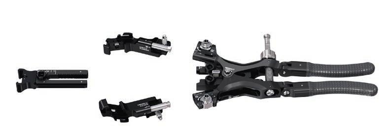
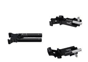
4 INSIGHT LATERAL ACCESS SYSTEM The INSIGHT Lateral Access System is a comprehensive modular system designed to support the minimal invasive approach to the spine. X Ray Visibility: Key parts are semi radiolucent (aluminum) for fluoroscopic visualization Radiolucent carbon fiber handles to avoid interference during anterior/ posterior fluoroscopy Low Profile Accessories: In blade embedded accessories maximize surgeon view Winglets to provide further 7 mm anterior/posterior soft tissue retraction Blade extensions to provide additional 0 mm of blade length in situ Disc anchor blade to increase retractor stability DePuy Synthes INSIGHT Lateral Access System Surgical Technique


5 Seamless Retraction: Speed nut for quick and fine adjustment of retractor opening up to 70 mm Retractor Blades: Click-on blades for quick assembly Blade length 40 to 80 mm Different Retraction Techniques: Various fixation points to strong arm system enables surgeon preferred technique: Backward retraction of third blade (fixation to retractor body) Forward retraction of left-right blades (fixation to third blade holder) Independent Angulation: Individual left and right blade angulation up to 0 Light System: Light accessory to illuminate the surgical field Disposable light with adjustable depth INSIGHT Lateral Access System Surgical Technique DePuy Synthes


6 DESCRIPTION OF RETRACTOR PARTS Angulation nuts Speed nut Accessory grooves PUSH button Light slot RETRACT nut Attachment point for connector for Strong Arm for backward retraction Attachment point for connector for Strong Arm for forward retraction Right blade holder Third blade holder Left blade holder Left and right blade DePuy Synthes INSIGHT Lateral Access System Surgical Technique
7 AO PRINCIPLES The four principles to be considered as the foundation for proper spine patient management underpin the design and delivery of the Curriculum: Stability Alignment Biology Function. Stability Stabilization to achieve a specific therapeutic outcome axial sagittal coronal Alignment Balancing the spine in three dimensions Biology Etiology, pathogenesis, neural protection, and tissue healing Function Preservations and restoration of function to prevent disability Copyright 0 by AOSpine INSIGHT Lateral Access System Surgical Technique DePuy Synthes
8 INDICATIONS AND CONTRAINDICATIONS Intended Purpose The INSIGHT Lateral Access System is a surgical access system intended to provide a minimally invasive approach to the thoracolumbar spine. It is designed for needs of various indications and/or surgical techniques. Indications and Contraindications In case the INSIGHT Lateral Access System is used in combination with implants or instruments, please refer to the respective technique guides for indications and contraindications and additional surgical steps. 6 DePuy Synthes INSIGHT Lateral Access System Surgical Technique
.")
9 PREPARATION Patient Positioning Instruments S Electrode Kit for Neuromonitoring Table Clamp for Universal Arm Strong Arm or Universal Arm For the lateral approach, the patient is placed and taped in the lateral decubitus position as illustrated (). Note: Ensure that the position of the operative level is perpendicular to the floor for easier orientation of fluoroscopy and approach by confirming: In lateral fluoroscopy, the endplates are parallel with superimposed pedicles. In A/P fluoroscopy, the endplates are parallel, the pedicles reside in the cranial portion of the vertebral body and the spinous process is equidistant to both pedicles. For further information, please refer to the dedicated implant technique guides. If neuromonitoring is being used, refer to the respective neuromonitoring technique guide. Precaution: A thorough education and a comprehensive understanding of the respective anatomy as well as practical experience in performing the lateral approach to the thoracolumbar spine is a prerequisite for use of this system. INSIGHT Lateral Access System Surgical Technique DePuy Synthes 7


10 Preparation Set Up Strong Arm System Install table clamp onto the preferred side of the operating table by loosening it and attaching it onto the table rail. Insert the strong arm or universal arm with flat side facing away from the table (). Secure table clamp by tightening it. Precaution: Ensure that the rotation of the strong arm or universal arm is securely locked by the table clamp. 8 DePuy Synthes INSIGHT Lateral Access System Surgical Technique

.")
11 ACCESS UND EXPOSURE Approach the Spine Locate and mark the correct operative level and associated incision site under lateral fluoroscopy and make a skin incision. Incision should be large enough to accommodate the retractor and subsequent retraction. Retract the subcutaneous tissue and bluntly dissect through the abdominal muscle layers and incise the transversalis fascia to enter the retroperitoneal space (). Move the peritoneum anterior with forefinger and continue with blunt dissection to gently palpate down to the psoas by following the anterior border of the quadratus lumborum (). Before puncturing the psoas, fluoroscopy is recommended to ensure targeting the area of interest of the affected disc space. The anterior third of the psoas muscle is the most likely safe zone for avoiding the neural elements of the lumbar plexus. Takatomo Moro, MD, Shin-ichi Kikuchi, MD, PhD, Shin-ichi Konno, MD, PhD and Hiroyuki Yaginuma, MD, PhD: An Anatomic Study of the Lumbar Plexus with Respect to Retroperitoneal Endoscopic Surgery., Spine 003; Volume 8, Number 5, pp INSIGHT Lateral Access System Surgical Technique DePuy Synthes 9
.")
12 Access und Exposure Neuromonitoring Instruments S S Neuromonitoring Stimulation Probe Electrode Kit for Neuromonitoring Handle for Neuromonitoring Stimulation Probe or Kirschner Wire 3.0 mm with blunt tip, length 85 mm, Stainless Steel In order to avoid neural structures it is recommended to use triggered EMG neuromonitoring (detection of motoric nerves). Additionally use direct visual control (detection of sensoric nerves). Note: With the eccentric dilation technique the retractor will be positioned a maximum of 8 mm off-center. Map out a safe corridor through the psoas muscle to the operating level by stimulating with the neuromonitoring probe (). Once achieved, continue to perform a blunt dissection of the psoas muscle under direct visual control. DePuy Synthes INSIGHT Lateral Access System Surgical Technique
13 Precaution: In addition, lateral and AP fluoroscopy should be utilized to place the neuromonitoring probe/k-wire through the psoas and into the annulus of the desired intervertebral disc space (). In case no neuromonitoring is used, the 3.0 mm Kirschner wire can be utilized. Precaution: Ensure the neuromonitoring probe or Kirschner wire remains securely in position until the retractor is in place by having it sufficiently anchored in the disc space. For further information, please refer to the dedicated implant technique guides and to the respective neuromonitoring technique guide. INSIGHT Lateral Access System Surgical Technique DePuy Synthes

 over the neuromonitoring probe or Kirschner wire in the orientation of preferred direction of dilation.")
14 Access und Exposure 3 Insert Dilators Instruments Dilator, 6 mm, eccentric, small, for INSIGHT Lateral Access System Dilator, 0 mm, eccentric, medium, for INSIGHT Lateral Access System Dilator, 6 mm, eccentric, large, for INSIGHT Lateral Access System S Neuromonitoring Stimulation Probe or Kirschner Wire 3.0 mm with blunt tip, length 85 mm, Stainless Steel The eccentric dilators allow for dilation away from any sensitive structures (e.g. posterior nerves). Slide the small dilator (rounded tip first) over the neuromonitoring probe or Kirschner wire in the orientation of preferred direction of dilation. Continue with the remaining two dilators with the groove for the stimulation probe facing the preferred direction of dilation (midline or eccentric ()). Precaution: Use fluoroscopy (lateral and AP) to determine location of dilators. Also ensure that dilators rest firmly against the vertebral body wall in order to determine an accurate skin depth measurement. Keep downward pressure on the dilators until the strong arm or universal arm has been fixed to the retractor. DePuy Synthes INSIGHT Lateral Access System Surgical Technique
.")
15 A second stimulation probe can be placed in the dilator groove in order to check on surrounding nerve structures (). By turning the outermost dilator with a second probe in place, surrounding tissue can be monitored for presence of motoric nervous structures (3). 3 Precaution: Do not stimulate against any instruments in the surgical field. Determine the appropriate retractor blade length from the markings on the dilators and round up to the next available blade length. Note: When determining the blade length, consider the surrounding anatomy (iliac crest, ribs etc). INSIGHT Lateral Access System Surgical Technique DePuy Synthes
 Assemble the retractor by attaching the blade holders to the retractor body (see chapter Cleaning Positions / Assembly p.")
.")
16 RETRACTION Preparation Instruments Retractor Body Screwdriver, for INSIGHT Lateral Access System Blade Holder, left, for No Blade Holder, right, for No Third Blade Holder, for No Blade, length mm (in 0 mm increments) Assemble the retractor by attaching the blade holders to the retractor body (see chapter Cleaning Positions / Assembly p. 37). Open the retractor by compressing the handles and turning the speed nut () and attach the appropriate blades (() top loading click-on connection). If a disc anchor will be used, a disc anchor blade of corresponding length should be attached to the third blade holder (see chapter Accessories, Additional Stability instruction p. 8). Note: The disc anchor blade can only be attached to the third blade holder. DePuy Synthes INSIGHT Lateral Access System Surgical Technique


17 Place Retractor In Zero Position: Close the retractor by releasing speed nut (). Return angulation of left and right blades to the zero position by turning the angulation nuts with the Screwdriver for INSIGHT Lateral Access System accordingly (). Set the third blade to zero position by pushing the PUSH button and/or turning the RETRACT nut in the appropriate direction at the same time (3) until the 0 on the third blade aligns with the 0 on the retractor body. 3 INSIGHT Lateral Access System Surgical Technique DePuy Synthes

18 Retraction Attach Connector Instruments Connector, for Strong Arm No Screwdriver, for INSIGHT Lateral Access System Optional Wrench, for INSIGHT Lateral Access System Attach connector to the respective point on the retractor (A or B, see next page) and tighten with the Screwdriver or wrench depending on tightening preference (). The connector can only be attached in the illustrated positions and orientations (from the left and right side) to avoid subsequent conflict with angulation mechanism. For the role of the different attachment options, see next page. DePuy Synthes INSIGHT Lateral Access System Surgical Technique

 relative to the fixed third blade holder.")

19 Forward/Backward Retraction Options Retract Forward If forward retraction is desired (A), attach the connector to the third blade holder connection point. A Subsequent clockwise rotation of the RETRACT nut results in forward retraction of the retractor body (with left and right blade holders) relative to the fixed third blade holder. or Retract Backward If backward retraction is desired (B), attach the connector to either one of the attachment points on the retractor body. B Subsequent clockwise rotation of the RETRACT nut results in backward retraction of the third blade holder relative to a fixed retractor body (with left and right blade holder). Precaution: Do not place any accessories before retraction. INSIGHT Lateral Access System Surgical Technique DePuy Synthes


20 Retraction Slide Retractor Over the Dilators Use fluoroscopic imaging to determine the position of the dilators (). Slide the retractor with the blades and connector attached over the dilators. Note: The handles of the retractor can be placed either anterior or posterior depending on surgeons preference. Use fluoroscopic imaging to determine the position of the retractor. Retractor blades should rest against the disc space and/or vertebral endplates in a perpendicular orientation to the disc space (). Maintain the dilators and retractor in place until the strong arm or universal arm has been fixed to the retractor. 90 DePuy Synthes INSIGHT Lateral Access System Surgical Technique


21 Precaution: In order to minimize tissue creep: Retractor blades must be in zero position (3) The retractor blades should be placed against the disc space and/or the vertebral endplates. 3 Precaution: Use fluoroscopic images to determine the position of the retractor. Identify presence of osteophytes. Do not apply excessive force when inserting retractor. Attach Retractor to Strong Arm or Universal Arm Attach connector to strong arm or universal arm (,,3) and tighten the stabilizing system by turning the knob on the arm (4). 4 Precaution: Do not maneuver operating-table after fixing the retractor with the strong arm or universal arm system as this may lead to movement of the retractor in the surgical field. 3 INSIGHT Lateral Access System Surgical Technique DePuy Synthes

22 Retraction 3 Retract Lateral Open the retractor in the cranial-caudal direction to the desired position by compressing the handles and turning the speed nut (). Use fluoroscopic images to determine the position of the retractor. Remove the dilators. Use caution when removing the dilators so as not to dislodge the probe/kirschner wire from the disc space. Note: Leave the stimulation neuromonitoring probe/ Kirschner wire in place for orientation while opening the retractor. DePuy Synthes INSIGHT Lateral Access System Surgical Technique

23 4 Retract Forward/Backward Instrument Screwdriver, for INSIGHT Lateral Access System To perform either forward or backward retraction (see A and B in chapter Forward/Backward Retraction Options instruction p. 7), turn the RETRACT nut clockwise with the screwdriver (). Use fluoroscopic imaging during retraction to determine and confirm the position. Precaution: The retractor should not be placed either too anterior or too posterior to minimize the risk of damage to adjacent structures. Always retract under direct visual control. INSIGHT Lateral Access System Surgical Technique DePuy Synthes
 while turning the RETRACT nut counterclockwise using the screwdriver (3).")
24 Retraction Release Forward/Backward Retraction To release the forward or backward retraction, push the button with corresponding laser etching PUSH () while turning the RETRACT nut counterclockwise using the screwdriver (3). 3 DePuy Synthes INSIGHT Lateral Access System Surgical Technique
25 5 Blade Angulation Instrument Screwdriver, for INSIGHT Lateral Access System If additional exposure of the surgical site is needed or if the exposure needs to be centralised around the neuromonitoring probe/kirschner wire, use the screwdriver to independently angle the right or left blade and turn it in the direction of the arrow etched on the retractor (). Use fluoroscopic imaging during change of angulation to determine the position of the blades. In order to reduce the angulation, turn the screwdriver in the other direction. Remove the neuromonitoring probe/kirschner wire. Precaution: Avoid retraction or angulation of the blades to the extent that the segmental vessels are exposed or tissue is over retracted. Precaution: To angle the blades, only turn the screwdriver finger-tight to avoid applying excessive force on the retracted tissue. For further information, please refer to the dedicated implant technique guide for the subsequent procedure. INSIGHT Lateral Access System Surgical Technique DePuy Synthes
26 6 Subsequent Levels Remove the retractor (see chapter Removal p. 3). Repeat patient positioning and neuromonitoring steps for subsequent levels. Note: Patient position may need to be adjusted (through table adjustment) in order to perform subsequent levels (see chapter Patient Positioning, described on p. 7). DePuy Synthes INSIGHT Lateral Access System Surgical Technique
27 ACCESSORIES Light System Instruments Blade, length mm (in 0 mm increments) Reusable Light, for INSIGHT Lateral Access System Bifurcated Light Cable, for No Adapter, for Light and Cable or S Disposable Light, for INSIGHT Lateral Access System, sterile Light Cable, for No S Adapter, for Light and Cable Optional Wolf Adapter, for Light Source Storz Adapter, for Light Source Olympus Adapter, for Light Source ACMI Adapter, for Light Source Screw the appropriate light source adapter (Wolf, Storz, Olympus or ACMI) onto the appropriate light cable and screw the light adapter(s) to the other end(s) of the cable. INSIGHT Lateral Access System Surgical Technique DePuy Synthes


28 Accessories Reusable Light Wolf Storz Olympus ACMI Disposalble Light Wolf Storz Olympus ACMI DePuy Synthes INSIGHT Lateral Access System Surgical Technique

. Depending on light source, temperature of the light, cables and/or adapters may exceed 43 C.")
29 Slide the reusable light () or disposable light () into the light slots. Secure light underneath the provided hooks. Connect the light cable to the light source. Turn on the light source. Precautions and Warnings Do not bend fiber optic cables/lights under a radius of 5 cm. Do not apply pressure on the light cable/lights using a sharp object. Exchange reusable light/cables if it collects fluid inside, appears broken or damaged. Avoid damaging the fiber surfaces at the ends of the light cable, as this will reduce the light output level. Do not use higher wattage than indicated for the light cables and reusable light (300 W). Depending on light source, temperature of the light, cables and/or adapters may exceed 43 C. Therefore avoid contact to user, patient, temperature-sensitive objects and flammable materials such as textiles (curtains) or near cotton swabs or pads that have been soaked with flammable fluids with these parts. The reusable light/disposable light should only be used with the associated light cables. Never leave the light system unattended when light is being transmitted from a light source. Never look directly into the highly intense light since this could cause severe injuries to the eyes. The light instruments containing fiber optics should not be ultrasonically cleaned. INSIGHT Lateral Access System Surgical Technique DePuy Synthes

 ().")
 before and while advancing (AP) the disc anchor into the intervertebral disc in order to confirm that its trajectory does not lead to")
30 Accessories Additional Stability Instruments Disc Anchor Blades, length 80 mm 80 mm (0 mm increments) Instrument for Disc Anchor Blade Inner Shaft, for Instrument for Disc Anchor Blade Turning Knob, for Instrument for Disc Anchor Blade Push Button, for Instrument for Disc Anchor Blade Attach the appropriate disc anchor blade on the third blade holder instead of a common blade. Assemble the instrument for disc anchor blade (see chapter Cleaning Positions/Assembly p. 44). When inserting the assembled instrument into the disc anchor blade, ensure that it is in the disengaged position (with the arrows at the distal end pointing together) (). Slide the instrument down the groove and push down until the disc anchor rests in the desired position (). Precaution: Check position under fluoroscopy (AP and lateral) before and while advancing (AP) the disc anchor into the intervertebral disc in order to confirm that its trajectory does not lead to bone or adjacent (anterior or posterior) structure damage. Always confirm the absence of nerves before inserting the disc anchor. DePuy Synthes INSIGHT Lateral Access System Surgical Technique
31 To retract the disc anchor, slide the instrument (in the disengaged position) () down the groove until it sits on the disc anchor component (3). 3 4 Rotate the turning knob to the engaged position (counter-clockwise) to engage the disc anchor component (4). Retract the disc anchor component by pulling up the instrument (5). Disengage the instrument by turning the knob to the disengaged position (clockwise) (6). Precaution: Do not retract the third blade holder once the disc anchor is in place. As the disc anchor component is permanently attached to the respective blade it must be cleaned according to its specific handling guidelines (see chapter Cleaning Positions/Assembly p. 4). 5 6 INSIGHT Lateral Access System Surgical Technique DePuy Synthes


. The blade extension provides an additional 0 mm in blade length ().")
.")


32 Accessories Additional Retraction 3 Instruments Accessories Instrument Blade Extension Winglet, right Winglet, left Blade, length mm (in 0 mm increments) 7 mm 7 mm Scoop, for INSIGHT Lateral Access System 0 mm To lengthen the blades and to minimise tissue creep, a blade extension can be used with the accessories instrument (). The blade extension provides an additional 0 mm in blade length (). 4 To minimise lateral tissue creep, winglets can be used. Each winglet provides an additional 7 mm in blade width (3). Screw the accessory fully onto the accessories instrument. The groove number on the blade corresponds to numbers / on back of the accessory (4). Precaution: Use the scoop with the blade extension and/or winglet to retract soft tissue. This is to minimize the risk of soft tissue damage due to compression by the blade extension and winglet. DePuy Synthes INSIGHT Lateral Access System Surgical Technique
.")

33 The scoop is used to retract soft tissue. Glide the scoop down on the concave side of the blades to the site of tissue creep. Push the soft tissue behind the blade (5). 5 Then slide the accessory down the respective accessory groove (6). 6 Turn the handle of the scoop counterclockwise (7) into the retractor opening until it no longer resides behind the blade and can be removed. 7 Unscrew the accessories instrument from the extension. Precaution: Do not reposition the retractor or perform further retraction after accessories are placed. Precaution: When inserting and removing subsequent instruments (curettes, trials etc.) ensure that they do not conflict with the retractor blades or accessories, noting that manipulation (including accessory removal) may be required to avoid conflict. INSIGHT Lateral Access System Surgical Technique DePuy Synthes 33

34 REMOVAL Instruments Accessories Instrument Screwdriver, for INSIGHT Lateral Access System Instrument for Disc Anchor Blade Inner Shaft, for Instrument for Disc Anchor Blade Turning Knob, for Instrument for Disc Anchor Blade Push Button, for Instrument for Disc Anchor Blade Switch off the light source and remove the light. Then remove/retract all remaining accessories/disc anchor component with the corresponding instruments (). Precaution: Before the retractor can be removed, all accessories (blade extensions and winglets) have to be removed (), the disc anchor has to be retracted and the retractor must be placed in the zero position. 33 DePuy Synthes INSIGHT Lateral Access System Surgical Technique
. Turn in the opposite direction of the etched arrows.")
35 The retractor has to be placed in the zero position as follows (): Close the left and right blades by loosening the speed nut on the retractor body (). Turn the angulation nuts on the left and right blade holder with the screwdriver to bring the blades back into the zero position (). Turn in the opposite direction of the etched arrows. Push the button etched with PUSH while turning the RETRACT nut counterclockwise (3) to bring the third blade holder into its original zero position. Loosen the strong arm by turning the knob on it counterclockwise and detach connector from strong arm or universal arm. Remove the retractor from the surgical field. 3 INSIGHT Lateral Access System Surgical Technique DePuy Synthes 33

36 Removal Removal After Surgery Instruments Blade Removal Tool Sleeve, for Blade Removal Tool No Screwdriver, for INSIGHT Lateral Access System Optional Wrench, for INSIGHT Lateral Access System Remove the connector for strong arm with the screwdriver or wrench by turning counterclockwise. For cleaning, reprocessing and storage, disassemble the blades from the retractor using the blade removal tool. Assemble the sleeve for blade removal tool onto the blade removal tool (see chapter Cleaning Positions / Assembly p. 40) ensuring that the sleeve is fully pulled back. Engage the assembled blade removal tool into the blade blade holder connection (). Advance the sleeve for the blade removal tool until the blade is engaged (). Alternatively, the flat spring can be compressed by hand without the sleeve. 33 DePuy Synthes INSIGHT Lateral Access System Surgical Technique
37 Pull the blade out (3). Retract the sleeve for the blade removal tool in order to release the blade. 3 Disassemble the blade holders from the retractor body according to the disassembling instructions (see chapter Cleaning Positions/Assembly illustrated on the next page). INSIGHT Lateral Access System Surgical Technique DePuy Synthes 33


38 CLEANING POSITIONS / ASSEMBLY Cleaning Positions /Assembly L R Page /3 33 DePuy Synthes INSIGHT Lateral Access System Surgical Technique


39 L! 3 3 L 4 3 R! Page /3 INSIGHT Lateral Access System Surgical Technique DePuy Synthes 33


40 R 6 3 7! Page 3/3 33 DePuy Synthes INSIGHT Lateral Access System Surgical Technique


41 SE_ AA 07/03 Synthes, Inc. or its affiliates All rights reserved Page / INSIGHT Lateral Access System Surgical Technique DePuy Synthes 33


42 Page / 44 DePuy Synthes INSIGHT Lateral Access System Surgical Technique

43 SE_ AA 05/03 Synthes, Inc. or its affiliates All rights reserved Page /4 INSIGHT Lateral Access System Surgical Technique DePuy Synthes 44

44 SE_ AA 05/03 Synthes, Inc. or its affiliates All rights reserved Page /4 44 DePuy Synthes INSIGHT Lateral Access System Surgical Technique


45 SE_ AA 05/03 Synthes, Inc. or its affiliates All rights reserved Page 3/4 INSIGHT Lateral Access System Surgical Technique DePuy Synthes 44


46 !! 7 SE_ AA 05/03 Synthes, Inc. or its affiliates All rights reserved 8 Page 4/4 44 DePuy Synthes INSIGHT Lateral Access System Surgical Technique


47 INSTRUMENTS Universal Arm Table Clamp for Universal Arm Retractor Body Blade Holder, left, for No Blade Holder, right, for No Third Blade Holder, for No INSIGHT Lateral Access System Surgical Technique DePuy Synthes


48 Instruments Screwdriver, for INSIGHT Lateral Access System Blade Removal Tool Sleeve, for Blade Removal Tool No Instrument for Disc Anchor Blade Inner Shaft, for Instrument for Disc Anchor Blade Turning Knob, for Instrument for Disc Anchor Blade Push Button, for Instrument for Disc Anchor Blade Wrench, for INSIGHT Lateral Access System Holder, for INSIGHT Lateral Access System Scoop, for INSIGHT Lateral Access System Accessories Instrument 6 DePuy Synthes INSIGHT Lateral Access System Surgical Technique

 INSIGHT Lateral Access System Surgical Technique DePuy Synthes 7")
49 Blade Extension Winglet, right Winglet, left Strong Arm Connector, for Strong Arm No Dilator, 6 mm, eccentric, small, for INSIGHT Lateral Access System Dilator, 0 mm, eccentric, medium, for INSIGHT Lateral Access System Dilator, 6 mm, eccentric, large, for INSIGHT Lateral Access System Blade, length 40 mm 90 mm (0 mm increments) Blade, length 00 mm 80 mm (0 mm increments) INSIGHT Lateral Access System Surgical Technique DePuy Synthes 7


50 Instruments Disc Anchor Blade for Third Blade Holder, length 80 mm 80 mm (0 mm increments) Reusable Light, for INSIGHT Lateral Access System Wolf Adapter, for Light Source Storz Adapter, for Light Source Olympus Adapter, for Light Source ACMI Adapter, for Light Source Bifurcated Light Cable, for No Light Cable, for No S Adapter, for Light and Cable S Disposable Light, for INSIGHT Lateral Access System, sterile 8 DePuy Synthes INSIGHT Lateral Access System Surgical Technique


51 INSTRUMENTS FOR NEUROMONITORING S Neuromonitoring Stimulation Probe S Electrode Kit for Neuromonitoring Handle for Neuromonitoring Stimulation Probe INSIGHT Lateral Access System Surgical Technique DePuy Synthes 9
52 TRAYS AND VARIO CASES The trays with the instruments for the INSIGHT Lateral Access System can be assembled to the needs of the surgeon. They can be stored in Vario Cases with corresponding height Tray, for Retractor and Dilators, (without ) for INSIGHT Lateral Access System instruments Tray, for Blades and Scoop, (without for INSIGHT Lateral Access System instruments) Tray, for Accessories and Blades, (without length mm, for INSIGHT Lateral instruments) Access System Tray, for Disc Anchor Blades, (without for INSIGHT Lateral Access System instruments) Tray, for Lighting Instruments, (without for INSIGHT Lateral Access System instruments) Vario Case, Framing, size /, height 88 mm Vario Case, Framing, size /, height 6 mm Lid (Stainless Steel), size /, for Vario Case Vario Case for Strong Arm (without System, with Lid, without Contents instruments) 55 DePuy Synthes INSIGHT Lateral Access System Surgical Technique
53
54
55
56 DSEM/SPN/054/005() 04/5 Synthes GmbH Eimattstrasse Oberdorf Switzerland Tel: Fax: This publication is not intended for distribution in the USA. All surgical techniques are available as PDF files at 03 DePuy Synthes Spine, a division of Synthes GmbH. 05. All rights reserved
Collinear Reduction Clamp
 For minimally invasive fracture reduction Collinear Reduction Clamp Surgical Technique Image intensifier control This description alone does not provide sufficient background for direct use of DePuy Synthes
TSLP Thoracolumbar Spine Locking Plate
 Anterior thoracolumbar spine locking plate TSLP Thoracolumbar Spine Locking Plate Surgical Technique Image intensifier control This description alone does not provide sufficient background for direct use
TELEFIX SURGICAL TECHNIQUE. Implant system for the anterior stabilization of the thoracolumbar spine
 TELEFIX Implant system for the anterior stabilization of the thoracolumbar spine Instruments and implants approved by the AO Foundation. This publication is not intended for distribution in the USA. SURGICAL
Handling Technique. Collinear Reduction Clamp. For minimally invasive fracture reduction.
 Handling Technique Collinear Reduction Clamp. For minimally invasive fracture reduction. Table of Contents Collinear Reduction Clamp 2 Handling Technique 4 Ordering Information 10 Warning This description
Technique Guide. Insight Retractor. Minimal invasive access system to the posterior thoracolumbar spine.
 Technique Guide Insight Retractor. Minimal invasive access system to the posterior thoracolumbar spine. Table of Contents Introduction Insight Retractor 2 AO Principles 4 Indications and Contraindications
USS II ILIO-SACRAL Modular System for Stable Fixation in the Sacrum and Illium
 USS II ILIO-SACRAL Modular System for Stable Fixation in the Sacrum and Illium Instruments and implants approved by the AO Foundation. This publication is not intended for distribution in the USA. TECHNIQUE
The Versatile Polyaxial Solution for the Universal Spine Systems. USS II Polyaxial. Surgical Technique
 The Versatile Polyaxial Solution for the Universal Spine Systems USS II Polyaxial Surgical Technique Image intensifier control This description alone does not provide sufficient background for direct use
Interbody fusion cage for the transforaminal approach. Travios. Surgical Technique
 Interbody fusion cage for the transforaminal approach Travios Surgical Technique Image intensifier control This description alone does not provide sufficient background for direct use of DePuy Synthes
Mini External Fixator.
 Mini External Fixator. Assembly and Surgical Technique This publication is not intended for distribution in the USA. Instruments and implants approved by the AO Foundation. Image intensifier control Warning
XRL A modular expandable radiolucent vertebral body replacement system
 XRL A modular expandable radiolucent vertebral body replacement system This publication is not intended for distribution in the USA. SURGICAL TECHNIQUE Table of Contents Introduction XRL 2 AO Spine Principles
CSLP-Cervical Spine Locking Plate
 For anterior, cervical fixation CSLP-Cervical Spine Locking Plate Surgical Technique Image intensifier control This description alone does not provide sufficient background for direct use of DePuy Synthes
The vertebral body replacement with ratchet mechanism. Synex. Surgical Technique
 The vertebral body replacement with ratchet mechanism Synex Surgical Technique Image intensifier control This description alone does not provide sufficient background for direct use of DePuy Synthes products.
In-Space. Interspinous distraction through a mini-open, posterior, unilateral approach.
 In-Space. Interspinous distraction through a mini-open, posterior, unilateral approach. Surgical Technique Posterior Approach PRODUCT OBSOLETED 30th September 2017 DSEM/SPN/0915/0348(1) This publication
LUMBAR POSTERIOR MINIMALLY INVASIVE SYSTEM. Surgical Technique
 LUMBAR POSTERIOR MINIMALLY INVASIVE SYSTEM Surgical Technique Joint Spine Sports Med M.U.S.T. Mini Open Surgical Technique Joint Spine Sports Med CAUTION Federal law (USA) restricts this device to sale
M.I.S. MAKE IT SMART IN ONE SYSTEM. Surgical Technique. Hip Knee Spine Navigation
 M.I.S. MAKE IT SMART IN ONE SYSTEM Surgical Technique Hip Knee Spine Navigation M.U.S.T. Mini Open Surgical Technique Hip Knee Spine Navigation 2 C O N T E N T S 1 INTRODUCTION 4 2 SURGICAL TECHNIQUE 5
Imola Lateral IBF System Surgical Technique
 Imola Lateral IBF System Surgical Technique IMOLA CIRCUIT TABLE OF CONTENTS Design Rationale Instructions for Use Surgical Technique 1. Table Mounting 2. Surgical Planning & Targeting 3. Access and Preparation
ARCH Laminoplasty System
 Dedicated System for Open-door Laminoplasty ARCH Laminoplasty System Surgical Technique Image intensifier control This description alone does not provide sufficient background for direct use of DePuy Synthes
LCP Low Bend Medial Distal Tibia Plates 3.5 mm. Anatomic plates with low profile head for intra- and extraarticular fractures.
 LCP Low Bend Medial Distal Tibia Plates 3.5 mm. Anatomic plates with low profile head for intra- and extraarticular fractures. Surgical Technique This publication is not intended for distribution in the
ECD EXPANDABLE CORPECTOMY DEVICE Continuously Expandable Vertebral Body Replacement for Tumour Cases
 ECD EXPANDABLE CORPECTOMY DEVICE Continuously Expandable Vertebral Body Replacement for Tumour Cases Instruments and implants approved by the AO Foundation. This publication is not intended for distribution
O PE RATIV E TE C HN IQ U E. ProView. Expandable Retractor System U.S. EDITION
 O PE RATIV E TE C HN IQ U E ProView M I N I M A L A C C E S S P O R TA L ( M A P ) S Y S T E M Expandable Retractor System U.S. EDITION Table of Contents 1 INTRODUCTION 2 OPERATIVE TECHNIQUE 9 PART NUMBERS
Technique Guide. Oracle Spacer System. Instruments and implants for a direct lateral approach to the lumbar spine.
 Technique Guide Oracle Spacer System. Instruments and implants for a direct lateral approach to the lumbar spine. Table of Contents Introduction Oracle Spacer System 2 AO Principles 4 Indications 5 Surgical
VECTRA-T SURGICAL TECHNIQUE. The Translational Anterior Cervical Palate System. This publication is not intended for distribution in the USA.
 VECTRA-T The Translational Anterior Cervical Palate System This publication is not intended for distribution in the USA. SURGICAL TECHNIQUE Image intensifier control This description alone does not provide
Mandible External Fixator II. Provides treatment for fractures of the maxillofacial area.
 Mandible External Fixator II. Provides treatment for fractures of the maxillofacial area. Technique Guide This publication is not intended for distribution in the USA. Instruments and implants approved
T-PAL. Transforaminal Posterior Atraumatic Lumbar Cage System.
 T-PAL. Transforaminal Posterior Atraumatic Lumbar Cage System. Technique Guide This publication is not intended for distribution in the USA. Instruments and implants approved by the AO Foundation. Image
PROXIMAL FEMORAL NAIL REMOVAL SET
 PROXIMAL FEMORAL NAIL REMOVAL SET for PFN, TFN and PFNA/PFNA-II Instruments and Implants approved by the AO Foundation. This publication is not intended for distribution in the USA. SURGICAL TECHNIQUE
SYNEX The vertebral body replacement with ratchet mechanism
 SYNEX The vertebral body replacement with ratchet mechanism Instruments and implants approved by the AO Foundation. This publication is not intended for distribution in the USA. SURGICAL TECHNIQUE Image
SynCage-C short. Surgical Technique. This publication is not intended for distribution in the USA.
 SynCage-C short Surgical Technique This publication is not intended for distribution in the USA. Instruments and implants approved by the AO Foundation. Table of contents Implants 2 Indications/contra-indications
OBSOLETED. LCP Medial Distal Tibia Plate, without Tab. The Low Profile Anatomic Fixation System with Angular Stability and Optimal Screw Orientation.
 LCP Medial Distal Tibia Plate, without Tab. The Low Profile Anatomic Fixation System with Angular Stability and Optimal Screw Orientation. Surgical Technique LCP Small Fragment System This publication
LCP Medial Distal Tibia Plate, without Tab. The Low Profile Anatomic Fixation System with Angular Stability and Optimal Screw Orientation.
 LCP Medial Distal Tibia Plate, without Tab. The Low Profile Anatomic Fixation System with Angular Stability and Optimal Screw Orientation. Technique Guide LCP Small Fragment System Table of Contents Introduction
SYNFIX EVOLUTION SECURED SPACER SYSTEM
 SYNFIX EVOLUTION SECURED SPACER SYSTEM Instruments and implants for stand-alone anterior lumbar interbody fusion Instruments and implants approved by the AO Foundation. This publication is not intended
SYNCAGE EVOLUTION. This publication is not intended for distribution in the USA. SURGICAL TECHNIQUE
 SYNCAGE EVOLUTION This publication is not intended for distribution in the USA. SURGICAL TECHNIQUE Image intensifier control Warning This description alone does not provide sufficient background for direct
FACET WEDGE. Facet joint fixation device.
 FACET WEDGE. Facet joint fixation device. Technique Guide Synthes FACET WEDGE Technique Guide /44 Synthes FACET WEDGE Technique Guide /44 Table of Contents Introduction FACET WEDGE 3 AO Principles 4 Indications
Spinal Correction FRA Spacer System. For use with the Small Stature FRA Spacer and the FRA Spacer.
 Spinal Correction FRA Spacer System. For use with the Small Stature FRA Spacer and the FRA Spacer. Technique Guide Instruments and implants approved by the AO Foundation Table of Contents Introduction
LCP Superior Clavicle Plate. The anatomically precontoured fixation system with angular stability for clavicle shaft and lateral clavicle.
 LCP Superior Clavicle Plate. The anatomically precontoured fixation system with angular stability for clavicle shaft and lateral clavicle. Surgical Technique This publication is not intended for distribution
In-Space. Percutaneous interspinous distraction.
 In-Space. Percutaneous interspinous distraction. Surgical Technique PRODUCT OBSOLETED 30th September 207 DSEM/SPN/095/0344() This publication is not intended for distribution in the USA. Instruments and
LCP Medial Proximal Tibial Plate 3.5. Part of the Synthes small fragment Locking Compression Plate (LCP) system.
 system.") LCP Medial Proximal Tibial Plate 3.5. Part of the Synthes small fragment Locking Compression Plate (LCP) system. Technique Guide This publication is not intended for distribution in the USA. Instruments
LCP Medial Proximal Tibial Plate 3.5. Part of the Synthes small fragment Locking Compression Plate (LCP) system. Technique Guide This publication is not intended for distribution in the USA. Instruments
Augmentable Pedicle Screws for Osteoporotic Bone. Perforated Click X. Surgical Technique
 Augmentable Pedicle Screws for Osteoporotic Bone Perforated Click X Surgical Technique Image intensifier control This description alone does not provide sufficient background for direct use of DePuy Synthes
PEEK Cage for Posterior Lumbar Interbody Fusion (PLIF) Plivios Revolution. Surgical Technique
 Plivios Revolution. Surgical Technique") PEEK Cage for Posterior Lumbar Interbody Fusion (PLIF) Plivios Revolution Surgical Technique Image intensifier control This description alone does not provide sufficient background for direct use of DePuy
PEEK Cage for Posterior Lumbar Interbody Fusion (PLIF) Plivios Revolution Surgical Technique Image intensifier control This description alone does not provide sufficient background for direct use of DePuy
Technique Guide. 3.5 mm LCP Low Bend Medial Distal Tibia Plate Aiming Instruments. Part of the 3.5 mm LCP Percutaneous Instrument System.
 Technique Guide 3.5 mm LCP Low Bend Medial Distal Tibia Plate Aiming Instruments. Part of the 3.5 mm LCP Percutaneous Instrument System. Table of Contents Introduction 3.5 mm LCP Low Bend Medial Distal
LCP Superior Clavicle Plate. The anatomically precontoured fixation system with angular stability for clavicle shaft and lateral clavicle.
 Technique Guide LCP Superior Clavicle Plate. The anatomically precontoured fixation system with angular stability for clavicle shaft and lateral clavicle. Table of Contents Introduction LCP Superior Clavicle
ARCH Laminoplasty System. Dedicated System for Open-door Laminoplasty.
 ARCH Laminoplasty System. Dedicated System for Open-door Laminoplasty. Surgical Technique This publication is not intended for distribution in the USA. Instruments and implants approved by the AO Foundation.
3.5 MM VA-LCP PROXIMAL TIBIA PLATE SYSTEM
 3.5 MM VA-LCP PROXIMAL TIBIA PLATE SYSTEM Part of the DePuy Synthes Variable Angle Periarticular Plating System SURGICAL TECHNIQUE TABLE OF CONTENTS INTRODUCTION 3.5 mm VA-LCP Proximal Tibial Plate 2 AO
Contact Fusion Cage. Surgical Technique
 Contact Fusion Cage Surgical Technique Image intensifier control This description alone does not provide sufficient background for direct use of DePuy Synthes products. Instruction by a surgeon experienced
ORACLE CAGE SYSTEM Comprehensive solution for lumbar interbody fusion using the direct lateral approach.
 ORACLE CAGE SYSTEM Comprehensive solution for lumbar interbody fusion using the direct lateral approach. Instruments and implants approved by the AO Foundation. This publication is not intended for distribution
SynCage. Surgical Technique. This publication is not intended for distribution in the USA. Instruments and implants approved by the AO Foundation.
 SynCage Surgical Technique This publication is not intended for distribution in the USA. Instruments and implants approved by the AO Foundation. Image intensifier control Warning This description alone
Periarticular Aiming Arm Instruments for LCP Proximal Tibial Plate 4.5/5.0. Part of the LCP Periarticular Aiming Arm Instrument System (large).
.") Technique Guide Periarticular Aiming Arm Instruments for LCP Proximal Tibial Plate 4.5/5.0. Part of the LCP Periarticular Aiming Arm Instrument System (large). Image intensifier control Warning This description
Technique Guide Periarticular Aiming Arm Instruments for LCP Proximal Tibial Plate 4.5/5.0. Part of the LCP Periarticular Aiming Arm Instrument System (large). Image intensifier control Warning This description
PERFORATED CLICK X Augmentable pedicle screws for osteoporotic bone
 PERFORATED CLICK X Augmentable pedicle screws for osteoporotic bone Instruments and implants approved by the AO Foundation. This publication is not intended for distribution in the USA. SURGICAL TECHNIQUE
ACIS Anterior Cervical Interbody Spacer
 Implants and Instruments for Interbody Fusion Available in both PEEK and ProTi 360º Titanium Integrated Technology ACIS Anterior Cervical Interbody Spacer Surgical Technique Image intensifier control This
Conventus CAGE PH Surgical Techniques
 Conventus CAGE PH Surgical Techniques Conventus Orthopaedics The Conventus CAGE PH (PH Cage) is a permanent implant comprised of an expandable scaffold, made from nitinol and titanium, which is deployed
USS Variable Axis Screw
 USS Variable Axis Screw Polyaxial side-opening pedicle screw Surgical technique Original Instruments and Implants of the Association for the Study of Internal Fixation AO/ASIF USS Variable Axis Screw
Humerus Block. Discontinued December 2016 DSEM/TRM/0115/0296(1) Surgical Technique. This publication is not intended for distribution in the USA.
 Surgical Technique. This publication is not intended for distribution in the USA.") Humerus Block Surgical Technique Discontinued December 2016 DSEM/TRM/0115/0296(1) This publication is not intended for distribution in the USA. Instruments and implants approved by the AO Foundation. Contents
Humerus Block Surgical Technique Discontinued December 2016 DSEM/TRM/0115/0296(1) This publication is not intended for distribution in the USA. Instruments and implants approved by the AO Foundation. Contents
Technique Guide. T-PAL. Transforaminal posterior atraumatic lumbar spacer system.
 Technique Guide T-PAL. Transforaminal posterior atraumatic lumbar spacer system. Table of Contents Introduction T-PAL 2 AO Principles 4 Indications and Contraindications 5 Surgical Technique Preparation
TABLE OF CONTENTS. 2 (8144 Rev 2)
") 1 (8144 Rev 2) TABLE OF CONTENTS Introduction Conventus CAGE TM - Proximal Humerus...3 Indications and Contraindications...4 Surgical Summary...5 Patient Positioning & Approach...6 Surgical Technique Plate
1 (8144 Rev 2) TABLE OF CONTENTS Introduction Conventus CAGE TM - Proximal Humerus...3 Indications and Contraindications...4 Surgical Summary...5 Patient Positioning & Approach...6 Surgical Technique Plate
Handling instructions. USS Low Profile. Thoracolumbar posterior fixation system.
 Handling instructions USS Low Profile. Thoracolumbar posterior fixation system. U Table of contents Introduction Indications and contraindications 3 USS Low Profile implants 4 Handling implants with stick
VA-LCP Anterior Clavicle Plate. The anatomically precontoured fixation system with angular stability for clavicle shaft and lateral clavicle.
 Technique Guide VA-LCP Anterior Clavicle Plate. The anatomically precontoured fixation system with angular stability for clavicle shaft and lateral clavicle. Table of Contents Introduction VA-LCP Anterior
MATRIX Spine System Deformity
 A Solution for Simple and Complex Spine Pathology MATRIX Spine System Deformity Surgical Technique Image intensifier control This description alone does not provide sufficient background for direct use
Transforaminal Lumbar Interbody Fusion Cage (TLIF)
") Transforaminal Lumbar Interbody Fusion age (TLIF) 990100010 DOULE ENGINE MEDIL MTERIL O., LTD. No. 218 Houxiang Road, Haicang District, Xiamen 361022, P.R.hina Tel: +86 592 6087101 Fax: +86 592 6587078
Transforaminal Lumbar Interbody Fusion age (TLIF) 990100010 DOULE ENGINE MEDIL MTERIL O., LTD. No. 218 Houxiang Road, Haicang District, Xiamen 361022, P.R.hina Tel: +86 592 6087101 Fax: +86 592 6587078
External Distal Radius Fixator. Supplement to the 8 mm rod fixator system
 External Distal Radius Fixator. Supplement to the 8 mm rod fixator system Surgical technique This publication is not intended for distribution in the USA. Instruments and implants approved by the AO Foundation
DOUBLE/TRIPLE PELVIC OSTEOTOMY PLATES For Treating Coxofemoral Joint Instability and Subluxation in Immature Dogs
 DOUBLE/TRIPLE PELVIC OSTEOTOMY PLATES For Treating Coxofemoral Joint Instability and Subluxation in Immature Dogs Instruments and implants approved by the AO Foundation. This publication is not intended
Technique Guide. Locking Attachment Plate. For treatment of periprosthetic fractures.
 Technique Guide Locking Attachment Plate. For treatment of periprosthetic fractures. Table of Contents Introduction Locking Attachment Plate 2 Indications 4 Surgical Technique Patient Positioning 5 Preparation
Technique Guide. StenoFix. Interspinous distraction after surgical decompression.
 Technique Guide StenoFix. Interspinous distraction after surgical decompression. Table of Contents Introduction StenoFix 2 Indications and Contraindications 4 Surgical Technique Preoperative Planning
Technique Guide. MATRIX Spine System MIS Instrumentation. The total solution for simple and complex spine pathology.
 Technique Guide MATRIX Spine System MIS Instrumentation. The total solution for simple and complex spine pathology. Table of Contents Introduction MATRIX Spine System MIS Instrumentation 2 AO Principles
Technique Guide. Oracle Cage System. Comprehensive solution for lumbar interbody fusion using the direct lateral approach.
 Technique Guide Oracle Cage System. Comprehensive solution for lumbar interbody fusion using the direct lateral approach. Image intensifier control Warning This description alone does not provide sufficient
Technique Guide. 3.5 mm LCP Low Bend Medial Distal Tibia Plates. Part of the Synthes locking compression plate (LCP) system.
 system.") Technique Guide 3.5 mm LCP Low Bend Medial Distal Tibia Plates. Part of the Synthes locking compression plate (LCP) system. Table of Contents Introduction 3.5 mm LCP Low Bend Medial Distal Tibia Plates
Technique Guide 3.5 mm LCP Low Bend Medial Distal Tibia Plates. Part of the Synthes locking compression plate (LCP) system. Table of Contents Introduction 3.5 mm LCP Low Bend Medial Distal Tibia Plates
Replacement Device A modular expandable radiolucent vertebral body replacement system
 XRL Vertebral Body Replacement Device A modular expandable radiolucent vertebral body replacement system SURGICAL TECHNIQUE TABLE OF CONTENTS Introduction XRL System 2 AO Principles 5 Indications and Contraindications
LCP Medial Proximal Tibial Plate 4.5/5.0. Part of the Synthes LCP periarticular plating system.
 LCP Medial Proximal Tibial Plate 4.5/5.0. Part of the Synthes LCP periarticular plating system. Technique Guide This publication is not intended for distribution in the USA. Instruments and implants approved
The Calcaneal Plate. The Synthes non-locking solution for the Calcaneus.
 The Calcaneal Plate. The Synthes non-locking solution for the Calcaneus. Surgical Technique This publication is not intended for distribution in the USA. Instruments and implants approved by the AO Foundation.
Cannulated Angled Blade Plate 3.5 and 4.5, 90.
 Cannulated Angled Blade Plate 3.5 and 4.5, 90. Technique Guide This publication is not intended for distribution in the USA. Instruments and implants approved by the AO Foundation. Table of Contents Introduction
Technique Guide. USS Small Stature/Pediatric. A multifaceted deformity system for use in patients of small stature.
 Technique Guide USS Small Stature/Pediatric. A multifaceted deformity system for use in patients of small stature. Image intensifier control Warning This description alone does not provide sufficient background
Threshold Pedicular Fixation System Surgical Technique
 Threshold Pedicular Fixation System Surgical Technique Table of Contents Patient Preparation and Positioning... 2 Determining Incision Location... 3 Assembling the Cannulated Awl... 4 Guide Wire Placement...
AccuVision Minimally Invasive Spinal Exposure System
 Surgical Technique AccuVision Minimally Invasive Spinal Exposure System Working Beyond the Tube Lighted blades for superior viewing Maximum stabilization Contents Introduction... Page 1 Features and Benefits...
LCP Superior Anterior Clavicle Plate. The anatomically precontoured fixation system with angular stability for clavicle shaft and lateral clavicle.
 LCP Superior Anterior Clavicle Plate. The anatomically precontoured fixation system with angular stability for clavicle shaft and lateral clavicle. Surgical Technique This publication is not intended for
Cervical Solutions. Optio-C Anterior Cervical Plate. with Allograft/Autograft. Surgical Technique Guide
 Cervical Solutions Optio-C Anterior Cervical Plate with Allograft/Autograft Surgical Technique Guide 2 Optio-C Anterior Cervical Plate with Allograft/Autograft Surgical Technique Guide The Optio-C System
Technique Guide. LCP Distal Fibula Plates. Part of the Synthes locking compression plate (LCP) system.
 system.") Technique Guide LCP Distal Fibula Plates. Part of the Synthes locking compression plate (LCP) system. Table of Contents Introduction LCP Distal Fibula Plates 2 AO Principles 4 Indications 5 Surgical Technique
Technique Guide LCP Distal Fibula Plates. Part of the Synthes locking compression plate (LCP) system. Table of Contents Introduction LCP Distal Fibula Plates 2 AO Principles 4 Indications 5 Surgical Technique
Thoracolumbar Spine Locking Plate (TSLP) System. A low-profile plating system for anterior stabilization of the thoracic and lumbar spine.
 System. A low-profile plating system for anterior stabilization of the thoracic and lumbar spine.") Thoracolumbar Spine Locking Plate (TSLP) System. A low-profile plating system for anterior stabilization of the thoracic and lumbar spine. Technique Guide Instruments and implants approved by the AO Foundation
Thoracolumbar Spine Locking Plate (TSLP) System. A low-profile plating system for anterior stabilization of the thoracic and lumbar spine. Technique Guide Instruments and implants approved by the AO Foundation
USS Variable Axis Screw (VAS) System. For posterior fixation of the lumbar spine.
 System. For posterior fixation of the lumbar spine.") USS Variable Axis Screw (VAS) System. For posterior fixation of the lumbar spine. Technique Guide Instruments and implants approved by the AO Foundation Table of Contents Introduction USS Variable Axis
USS Variable Axis Screw (VAS) System. For posterior fixation of the lumbar spine. Technique Guide Instruments and implants approved by the AO Foundation Table of Contents Introduction USS Variable Axis
operative technique Universal Application
 operative technique Universal Application Introduction Introduction Building upon the design rationale of the Xia Spinal System, the new Xia Spinal System represents the latest advancement in spinal implant
Distal Radius Plate Instrument and Implant Set. Discontinued December 2017 DSUS/TRM/0916/1063(1)
") Distal Radius Plate Instrument and Implant Set Surgical Technique Discontinued December 2017 DSUS/TRM/0916/1063(1) The Distal Radius Plates Indications For fixation of fractures and osteotomies, including
Distal Radius Plate Instrument and Implant Set Surgical Technique Discontinued December 2017 DSUS/TRM/0916/1063(1) The Distal Radius Plates Indications For fixation of fractures and osteotomies, including
LCP Medial Proximal Tibial Plate 3.5. Part of the Synthes small fragment Locking Compression Plate (LCP) system.
 system.") LCP Medial Proximal Tibial Plate 3.5. Part of the Synthes small fragment Locking Compression Plate (LCP) system. Surgical Technique This publication is not intended for distribution in the USA. Instruments
LCP Medial Proximal Tibial Plate 3.5. Part of the Synthes small fragment Locking Compression Plate (LCP) system. Surgical Technique This publication is not intended for distribution in the USA. Instruments
Minimally Invasive Posterior Instruments
 A Comprehensive Set Supporting Both Direct and Transforaminal Posterior Approaches to the Lumbar Spine Minimally Invasive Posterior Instruments Support mini-open procedures and ideal for use with Minimally
3.5 mm LCP Low Bend Medial Distal Tibia Plate Aiming Instruments
 Part of the 3.5 mm LCP 3.5 mm LCP Low Bend Medial Distal Tibia Plate Aiming Instruments Surgical Technique TABLE OF CONTENTS INTRODUCTION 3.5 mm LCP Low Bend Medial Distal Tibia Plate 2 Aiming Instruments
Technique Guide. Neuromonitoring Kit. Triggered EMG for lateral approach.
 Technique Guide Neuromonitoring Kit. Triggered EMG for lateral approach. Table of Contents Introduction Principle of t-emg Monitoring 2 Neuromonitoring Kit 2 t-emg for Lateral Approach 3 AO Principles
ACIS Anterior Cervical Interbody Spacer
 An enhanced system of implants and instruments for interbody fusion ACIS Anterior Cervical Interbody Spacer Surgical Technique Image intensifier control This description alone does not provide sufficient
Luminary ALIF. Disc preparation and implant insertion instruments.
 Luminary ALIF. Disc preparation and implant insertion instruments. Technique Guide Instruments and implants approved by the AO Foundation Table of Contents Introduction Luminary ALIF 2 AO Principles 4
Technique Guide. ArcoFix. Anterior-only reduction plate.
 Technique Guide ArcoFix. Anterior-only reduction plate. Table of Contents Introduction ArcoFix 2 AO Principles 4 Indications and Contraindications 5 Surgical Technique Preoperative Planning 6 Insert ArcoFix
Valencia Pedicle Screw Surgical Technique
 Valencia Pedicle Screw Surgical Technique VALENCIA CIRCUIT TABLE OF CONTENTS Design Rationale Indications for Use Surgical Technique 1. Pedicle Preparation 2. Screw Insertion 3. Rod Placement 4. Locking
Cannulated Pediatric Osteotomy System (CAPOS). A single system of osteotomy blade plates and cannulated instrumentation.
. A single system of osteotomy blade plates and cannulated instrumentation.") Cannulated Pediatric Osteotomy System (CAPOS). A single system of osteotomy blade plates and cannulated instrumentation. Technique Guide This publication is not intended for distribution in the USA. Instruments
Cannulated Pediatric Osteotomy System (CAPOS). A single system of osteotomy blade plates and cannulated instrumentation. Technique Guide This publication is not intended for distribution in the USA. Instruments
The NBX Non-Bridging External Fixator A Non-Bridging External Fixator/Locking Plate capturing a series of.062mm K-wires and 3mm half-pins that are
 The NBX Non-Bridging External Fixator A Non-Bridging External Fixator/Locking Plate capturing a series of.062mm K-wires and 3mm half-pins that are inserted in a multiplanar and multi-directional fashion
Technique Guide. ECD Expandable Corpectomy Device. Continuously Expandable Vertebral Body Replacement for Tumour Cases.
 Technique Guide ECD Expandable Corpectomy Device. Continuously Expandable Vertebral Body Replacement for Tumour Cases. Table of Contents Introduction Overview 2 AO ASIF Principles 4 Indications and Contraindications
The minimally invasive Schanz Screw system for complete spinal fracture reduction. USS Fracture MIS. Surgical Technique
 The minimally invasive Schanz Screw system for complete spinal fracture reduction USS Fracture MIS Surgical Technique Image intensifier control This description alone does not provide sufficient background
LCP Metaphyseal Plates. For extra-articular fractures.
 LCP Metaphyseal Plates. For extra-articular fractures. Surgical Technique This publication is not intended for distribution in the USA. Instruments and implants approved by the AO Foundation. Image intensifier
Technique Guide. USS Fracture MIS. The minimally invasive Schanz Screw system for complete spinal fracture reduction.
 Technique Guide USS Fracture MIS. The minimally invasive Schanz Screw system for complete spinal fracture reduction. Image intensifier control Warning This description alone does not provide sufficient
TECHNICAL BROCHURE. Capture Facet Fixation System
 TECHNICAL BROCHURE Capture Facet Fixation System Table of Contents Product Overview...2 Instruments...4 Capture Facet Screw Surgical Technique Patient Preparation and Positioning...6 Guide Pin Placement...7
SYNFIX. LR Stand Alone Spacer. Instruments and implants for stand alone anterior lumbar interbody fusion (ALIF). Technique Guide
. Technique Guide") SYNFIX LR Stand Alone Spacer. Instruments and implants for stand alone anterior lumbar interbody fusion (ALIF). Technique Guide Table of Contents Introduction SYNFIX LR Stand Alone Spacer 2 AO Principles
SYNFIX LR Stand Alone Spacer. Instruments and implants for stand alone anterior lumbar interbody fusion (ALIF). Technique Guide Table of Contents Introduction SYNFIX LR Stand Alone Spacer 2 AO Principles
Technique Guide. 3.5 mm LCP Olecranon Plates. Part of the Synthes locking compression plate (LCP) system.
 system.") Technique Guide 3.5 mm LCP Olecranon Plates. Part of the Synthes locking compression plate (LCP) system. Table of Contents Introduction 3.5 mm LCP Olecranon Plates 2 AO Principles 3 Indications 3 Clinical
Technique Guide 3.5 mm LCP Olecranon Plates. Part of the Synthes locking compression plate (LCP) system. Table of Contents Introduction 3.5 mm LCP Olecranon Plates 2 AO Principles 3 Indications 3 Clinical
Alignment Rod. For intraoperatively confirming correction of the mechanical leg axis.
 Alignment Rod. For intraoperatively confirming correction of the mechanical leg axis. Easy to use Accuracy of surgery Reduces X-ray exposure Table of Contents Introduction Alignment Rod 2 Handling Technique
LCP DISTAL TIBIA PLATE
 LCP DISTAL TIBIA PLATE Instruments and implants approved by the AO Foundation. This publication is not intended for distribution in the USA. SURGICAL TECHNIQUE Image intensifier control This description
PediLoc 3.5mm and 4.5mm Contour Femur Plate Surgical Technique
 PediLoc 3.5mm and 4.5mm Contour Femur Plate Surgical Technique Surgical Technique Contour Femur Plate The technique description herein is made available to the healthcare professional to illustrate the
Olecranon Osteotomy Nail. For simple fractures and osteotomies of the olecranon.
 Olecranon Osteotomy Nail. For simple fractures and osteotomies of the olecranon. Technique Guide Discontinued June 2016; AVAILABLE FOR IMPLANT REMOVAL PURPOSES ONLY DSEM/TRM/0517/0843 Table of Contents
Distal Radius Plate 2.4/2.7 dorsal and volar
 Distal Radius Plate 2.4/2.7 dorsal and volar Surgical Technique This publication is not intended for distribution in the USA. Instruments and implants approved by the AO Foundation. Distal Radius Plate