VA-LCP Ankle Trauma System 2.7/3.5. Our most comprehensive ankle plating system.
|
|
|
- Rebecca Weaver
- 6 years ago
- Views:
Transcription


1 VA-LCP Ankle Trauma System 2.7/3.5. Our most comprehensive ankle plating system. Surgical Technique This publication is not intended for distribution in the USA. Instruments and implants approved by the AO Foundation.
2 Image intensifier control This description alone does not provide sufficient background for direct use of DePuy Synthes products. Instruction by a surgeon experienced in handling these products is highly recommended. Processing, Reprocessing, Care and Maintenance For general guidelines, function control and dismantling of multi-part instruments, as well as processing guidelines for implants, please contact your local sales representative or refer to: For general information about reprocessing, care and maintenance of Synthes reusable devices, instrument trays and cases, as well as processing of Synthes non-sterile implants, please consult the Important Information leaflet (SE_023827) or refer to:
3 Table of Contents Introduction VA-LCP Ankle Trauma System 2.7/3.5 2 AO Principles 4 Indications 5 Surgical Techniques Preparation 6 Patient Positioning 7 Approach and Incision 8 Reduce Articular Surface 9 Plate Insertion 11 Plate Positioning and Provisional Fixation 13 Insertion of VA Locking Screws B 2.7 mm 14 Use of Compression/Distraction System 20 Insertion of VA Locking Screws B 3.5 mm 25 Confirmation of Reduction and Fixation 28 Implant Removal 29 Optional Techniques 30 Medial and Anteromedial Plates 30 Insertion of Distal Cortex Screw B 3.5 mm 30 Insertion of VA Locking Screws B 2.7 mm 31 in Anterior Arm Distal Fibula Plates 32 Insertion of Cortex Screw(s) B 3.5 mm and 32 B 4.0 mm in Syndesmotic Slots All Plates 34 Insertion of Low Profile Metaphyseal 34 Compression Screws B 2.7 mm Product Information Plates 35 Screws 40 Instruments 43 MRI Information 51 VA-LCP Ankle Trauma System 2.7/3.5 Surgical Technique DePuy Synthes 1
 options for the medial,")
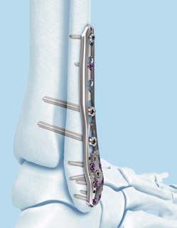
4 VA-LCP Ankle Trauma System 2.7/3.5. Our most comprehensive ankle plating system. Our most comprehensive ankle plating system addresses the individual surgeon s preferences, offering low-profile variable angle locking compression plating (VA-LCP) options for the medial, anteromedial, anterolateral and posterolateral aspects of the distal tibia, and the lateral distal fibula. Note: For information on fixation principles using conventional and locked plating techniques, please refer to the LCP Locking Compression Plate Surgical Technique (DSEM/ TRM/0115/0278). 2.7 mm variable angle locking screws Capture small fracture fragments Distribution of screws across the pilon (as shown in figure 1) 1 VA-LCP Anterolateral Distal Tibia Plate 2.7/3.5 Reduced risk of soft-tissue irritation Thin cross-section Smooth plates with rounded edges Anatomically pre-shaped Minimal screwhead prominence 2 LCP Anterolateral Distal Tibial Plate 3.5 Cross-sections of the VA-LCP Anterolateral Distal Tibial Plate 2.7/3.5 (1) and LCP Anterolateral Distal Tibial Plate 3.5 (2) at the level of the distal tibial pilon. 2 DePuy Synthes VA-LCP Ankle Trauma System 2.7/3.5 Surgical Technique


5 Compression / distraction forceps Syndesmotic screw Secure syndesmotic fixation option through the elongated hole in the VA-LCP Lateral Distal Fibula Plate 2.7. VA-LCP Ankle Trauma System 2.7/3.5 Surgical Technique DePuy Synthes 3

6 AO Principles In 1958, the AO formulated four basic principles, which have become the guidelines for internal fixation.¹, ² Anatomic reduction Fracture reduction and fixation to restore anatomical relationships. 1 2 Stable fixation Fracture fixation providing absolute or relative stability, as required by the patient, the injury, and the personality of the fracture. Early, active mobilization Early and safe mobilization and rehabilitation of the injured part and the patient as a whole. 4 3 Preservation of blood supply Preservation of the blood supply to soft tissues and bone by gentle reduction techniques and careful handling. Copyright 2007 by AO Foundation ¹ Müller ME, M Allgöwer, R Schneider, H Willenegger. Manual of Internal Fixation. 3rd ed. Berlin Heidelberg New York: Springer ² Rüedi TP, RE Buckley, CG Moran. AO Principles of Fracture Management. 2nd ed. Stuttgart, New York: Thieme DePuy Synthes VA-LCP Ankle Trauma System 2.7/3.5 Surgical Technique


7 Indications VA-LCP Medial Distal Tibial Plate 2.7/3.5 Indicated for complex intra- and extra-articular fractures of the distal tibia. VA-LCP Anteromedial Distal Tibial Plate 2.7/3.5 Indicated for complex intra- and extra-articular fractures of the distal tibia. VA-LCP Anterolateral Distal Tibial Plate 2.7/3.5 Indicated for complex intra- and extra-articular fractures of the distal tibia. VA-LCP Lateral Distal Fibula Plate 2.7 Indicated for fractures and non-unions of the metaphyseal and diaphyseal region of the distal fibula, especially in osteopenic bone. VA-LCP Posterolateral L- and T-Plates 2.7 Indicated for buttressing of partial articular fractures and bone fragments of the distal tibia. VA-LCP Ankle Trauma System 2.7/3.5 Surgical Technique DePuy Synthes 5
8 Preparation Required set(s): Plates, Stainless Steel VA-LCP Medial Distal Tibial Plates 2.7/3.5 or VA-LCP Anterolateral Distal Tibial Plates 2.7/3.5 or VA-LCP Lateral Distal Fibula Plates 2.7 or VA-LCP Posterolateral Distal Tibial L and T Plates 2.7 or VA-LCP Anteromedial Distal Tibial Plates 2.7/3.5 or VA-LCP Distal Tibial and Fibula Plates 2.7/3.5 Notes: The direction of the VA locking screws is determined by the design of the plate and based on the average anatomy of the specific bone. If manual plate contouring in the metaphyseal area is necessary, or if the implant does not match the normal patient anatomy, confirm the distal screw trajectories using Kirschner wires. Complete the preoperative radiographic assessment and prepare the preoperative plan. Determine plate length and instruments to be used. Visualization under image intensifier control in both the lateral and AP views is recommended. Screws, Stainless Steel VA-Locking and Cortex Screws B 2.7 mm VA-Locking and Cortex Screws B 3.5 mm Instruments Instruments for VA-Locking and Cortex Screw Insertion Instruments for VA-Locking and Cortex Screw Insertion Reduction Instruments 6 DePuy Synthes VA-LCP Ankle Trauma System 2.7/3.5 Surgical Technique


9 Patient Positioning Medial, anteromedial and anterolateral plates Position the patient supine on a radiolucent operating table. Elevate the leg on a padded rest with the knee moderately flexed to assist placement in a neutral position. Place the opposite leg level on a tabletop. Fibula plate Position the patient supine on a radiolucent operating table with a sandbag (bump) underneath the buttock of the affected side. This allows the foot to lie in a neutral position and prevents the normal external rotation of the leg. Posterolateral L- and T-plates If using a posterior approach, position the patient prone on a radiolucent operating table. Pad bony prominences and take care with arm positioning. The ipsilateral posterior iliac crest may be prepped if autogenous bone grafting is desired. Use a sterile thigh tourniquet in this situation. A small towel bump under the anterior aspect of the operative limb facilitates obtaining a lateral image while avoiding the contralateral limb. This bump is also useful to avoid an apex anterior deformity from the foot abutting the table. VA-LCP Ankle Trauma System 2.7/3.5 Surgical Technique DePuy Synthes 7


10 Approach and Incision Medial and anteromedial plates For a percutaneous approach, make an incision to access the medial malleolus. For an open approach, extend the incision as much as necessary to expose the joint. Precaution: When choosing a percutaneous approach, take care not to damage the saphenous nerve or saphenous vein. Anterolateral plate A longitudinal and straight incision should be centered at the ankle joint, parallel to the fourth metatarsal distally, and between the tibia and fibula proximally. Proximal extension of the incision should end 7 8 cm above the joint. Distally the incision can be extended to the level of the talonavicular joint, allowing exposure of the talar neck. The joint can be exposed using an arthrotomy. Fibula plate Make a straight lateral or posterolateral surgical incision to expose the fibular fracture, the distal fibula, and the fibular diaphysis. A lateral incision directly over the fibula can accentuate plate prominence and the wound closure will be directly over the implant. Alternatively, make the incision along the posterolateral border of the fibula where there is improved soft-tissue coverage. Precaution: Be careful not to damage the superficial peroneal nerve proximally and anteriorly, or the sural nerve posteriorly. Deep dissection allows exposure of the fibula along its length. An extraperiosteal approach to the fibula proximal to the fracture is usually preferred. 8 DePuy Synthes VA-LCP Ankle Trauma System 2.7/3.5 Surgical Technique

11 Reduce Articular Surface Instruments Periarticular Reduction Forceps, with pointed ball tips B 6.5 mm, small Periarticular Reduction Forceps, with pointed ball tips B 6.5 mm, medium Compression Forceps, large, with Speed Lock Distraction Forceps, large, with Speed Lock Compression Wire B 2.8 mm, length 200 mm, thread length mm In spiral or oblique fracture patterns, a periarticular reduction forceps can be applied for reduction. Alternatively, in some fracture patterns the plate can be used to assist with and guide the reduction. This may be especially important in comminuted fractures where a bridging technique is used. VA-LCP Ankle Trauma System 2.7/3.5 Surgical Technique DePuy Synthes 9
12 Reduce Articular Surface Note: Use of the compression or distraction forceps may facilitate obtaining length, fracture reduction and visualization of the joint. Confirm the reduction under image intensifier control. Options for maintaining the reduction depend on the fracture configuration and include: Periarticular reduction forceps Kirschner wires through the plate Compression wires, rods and compression or distraction forceps Independent lag screws Lag screws through the plate VA locking screws through the plate Note: To verify that independent lag screws and Kirschner wires will not interfere with plate placement, evaluate placement intraoperatively with AP and lateral fluoroscopic images. Precaution: VA locking and locking screws do not provide interfragmentary compression. Therefore, any desired compression must be achieved with non-locking screws. The articular surface must be reduced and compressed before fixation of the plate with VA locking screws. 11 DePuy Synthes VA-LCP Ankle Trauma System 2.7/3.5 Surgical Technique

13 Plate Insertion Instruments Drill Sleeve 2.7, for Aiming Arm No , for DHP Guiding Block for right/left VA-LCP Medial Distal Tibial Plate 2.7/3.5 or Guiding Block for right/left VA-LCP Antero lateral Distal Tibial Plate Plate 2.7/3.5 or Guiding Block for right/left VA-LCP Lateral Distal Fibula Plate Screwdriver Shaft Stardrive 3.5, T15, self holding, for AO/ASIF Quick Coupling Silicone Handle with AO/ASIF Quick Coupling Compression/Distraction Rod 2.7, Torque Limiter, 1.2 Nm, with AO/ASIF Quick Coupling VA-LCP Ankle Trauma System 2.7/3.5 Surgical Technique DePuy Synthes 11

14 Plate Insertion Percutaneous insertion Guiding blocks can be used in combination with drill sleeves 2.7 for percutaneous plate insertion. Attach the guiding block to the plate using the attachment screw and screwdriver shaft. Thread drill sleeves 2.7 securely into two of the most distal locking screw holes and use them as handles for percutaneous insertion. Insert the plate through the incision. Carefully push the plate under the soft tissue. Note: The drill sleeves 2.7 ( ) should only be used with a guiding block. The guiding block aligns the drill sleeve to ensure correct thread engagement. Open insertion Open the area as much as necessary to expose the fracture site. Carefully push the plate under the soft tissue for placement on the shaft. Use image intensifier control during plate placement in both the AP and lateral planes to ensure safe implant placement proximally along the shaft. 11 DePuy Synthes VA-LCP Ankle Trauma System 2.7/3.5 Surgical Technique


15 Plate Positioning and Provisional Fixation Instruments Kirschner Wire B 1.6 mm with trocar tip, length 150 mm, Stainless Steel Compression Wire B 2.8 mm, length 200 mm, thread length mm After plate insertion, use image intensifier control to check alignment on the bone. Make any adjustments before inserting screws. The plate may be temporarily held in place using any of the following options: Periarticular reduction forceps 1.6 mm Kirschner wires through the plate head and guiding block or plate shaft tip 2.8 mm compression wire in elongated combi-hole Cortex screw in a distal combi-hole Standard plate-holding forceps Any of these options will allow plate positioning adjustments and prevent plate rotation while inserting the first VA locking screw in the plate head. Note: Ensure proper reduction before inserting the first VA locking screw. Once the VA locking screws are inserted, further reduction is not possible without loosening the VA locking screws. Verify plate placement using image intensifier control. Make any adjustments before inserting screws. VA-LCP Ankle Trauma System 2.7/3.5 Surgical Technique DePuy Synthes 11
16 Insertion of VA Locking Screws 2.7 mm Instruments VA-LCP Drill Sleeve 2.7, for Drill Bits B 2.0 mm Depth Gauge, percutaneous Drill Bit B 2.0 mm, with double marking, length 140/115 mm, 3-flute, for Quick Coupling Silicone Handle with AO/ASIF Quick Coupling Screwdriver Shaft, Stardrive, T8, self-holding Torque Limiter, 1.2 Nm, with AO/ASIF Quick Coupling Handle for Torque Limiters 0.4/0.8/1.2 Nm Drill Sleeve 2.7, for Aiming Arm No , for DHP Guiding Block for right/left VA-LCP Medial Distal Tibial Plate 2.7/3.5 or Guiding Block for right/left VA-LCP Anterolateral Distal Tibial Plate 2.7/3.5 or Guiding Block for right/left VA-LCP Lateral Distal Fibula Plate DePuy Synthes VA-LCP Ankle Trauma System 2.7/3.5 Surgical Technique

17 1 Drill screw hole For insertion at variable angle Remove the guiding block for insertion of the VA locking screws off the nominal axis. Insert the cone-shaped end of drill guide into the desired VA locking hole in the plate. The drill guide cone will self-retain in the hole. The cone-shaped end of the drill guide allows drilling within a 30 cone. When drilling off nominal axis the drill guide should remain in place and the drill bit may be aimed in any direction within the cone. Verify the drill bit angle and depth under image intensifier control to ensure the desired angle has been achieved. If necessary, drill at a different angle and verify again. VA-LCP Ankle Trauma System 2.7/3.5 Surgical Technique DePuy Synthes 11
18 Insertion of VA Locking Screws B 2.7 mm Precautions: For the medial and anteromedial plates, a minimum of five B 2.7 mm VA locking screws should be inserted distally. For the anterolateral plate, a minimum of seven 2.7 mm VA locking screws should be inserted distally. Required number of distal VA locking screws B 2.7 mm Plate type Number of screws VA-LCP Medial Distal Tibial Plate 2.7/3.5 5 VA-LCP Anteromedial Distal Tibial Plate 2.7/3.5 5 VA-LCP Anterolateral Distal Tibial Plate 2.7/3.5 7 Precautions: Avoid excessive re-drilling, especially in poor quality bone. When inserting screws into the anterior arm of the anteromedial plate, the screw lengths should not exceed 26 mm to prevent collisions with other screws and joint surface penetration. 11 DePuy Synthes VA-LCP Ankle Trauma System 2.7/3.5 Surgical Technique

 to drill at the nominal angle in the plate head. Note: The drill sleeve 2.7 must be used with the guiding block.")
19 For screw insertion at nominal angle VA locking screws can be inserted into the plate at the predefined nominal screw trajectory. Option A: Universal drill guide Use the coaxial end of the universal VA locking drill guide 2.0. The drill guide will self-retain in the hole. If the drill bit with depth mark ( ) is used, the drilling depth can be read from the scale on the drill guide. Option B: Guiding blocks Use guiding blocks in combination with the drill sleeve 2.7 ( ) to drill at the nominal angle in the plate head. Note: The drill sleeve 2.7 must be used with the guiding block. Attach the guide block to the plate using the attachment screw and screwdriver shaft. Be sure to attach the correct sided guide block to the plate (right guide block to right plate). If the incorrect side is attached, not all of the 2.7 mm screw holes will be accessible and those that are will not be aimed correctly. Drill to the desired depth. Verify the drill depth under image intensifier control. Notes: If using non-locking screws or inserting VA locking screws off axis, the guide block and threaded drill guide cannot be used. If inserting a 2.7 mm metaphyseal screw, the guide block cannot be used. VA-LCP Ankle Trauma System 2.7/3.5 Surgical Technique DePuy Synthes 11


20 Insertion of VA Locking Screws B 2.7 mm 2 Measure screw length Use the depth gauge to measure for the correct screw length. The percutaneous depth gauge can be used through the guiding block. Note: When measuring for B 2.7 mm VA locking screws, the depth gauge can be used without the adapter sleeve. 3 Insert screws Insert the correct length VA locking screw. Confirm screw position and length prior to final tightening. Always use the torque limiter to finally tighten screws. Precaution: Initial insertion of the VA locking screws may be performed using power equipment. Do not finally lock the screws with power tools. Note: The fibula plate has a hole to accommodate a 2.7 mm metaphyseal or cortex screw distally. 11 DePuy Synthes VA-LCP Ankle Trauma System 2.7/3.5 Surgical Technique

21 If screws are inserted at the nominal angle, the same screw insertion technique can be applied with the guiding blocks. Required number of distal VA locking screws B 2.7 mm Plate type Number of screws VA-LCP Medial Distal Tibial Plate 2.7/3.5 5 VA-LCP Anteromedial Distal Tibial Plate 2.7/3.5 5 VA-LCP Anterolateral Distal Tibial Plate 2.7/3.5 7 VA-LCP Ankle Trauma System 2.7/3.5 Surgical Technique DePuy Synthes 11
22 Use of Compression/Distraction System 1 Insert compression wire Instruments Compression Wire B 2.8 mm, length 200 mm, thread length mm Compression/Distraction Rod 2.7, Compression/Distraction Rod 3.5, Handle for Torque Limiters 0.4/0.8/1.2 Nm Torque Limiter, 1.2 Nm, with AO/ASIF Quick Coupling Screwdriver Shaft, Stardrive, T8, self-holding Handle with Torque Limiting Function, 2.5 Nm Screwdriver Shaft Stardrive 3.5, T15, self-holding, for AO/ASIF Quick Coupling Place the plate on the bone, ensuring appropriate placement according to the specific procedure. Estimate the appropriate thread length needed for the plate-bone combination and choose the appropriate compression wire length. Note: Bicortical fixation is recommended. 22 DePuy Synthes VA-LCP Ankle Trauma System 2.7/3.5 Surgical Technique


23 Use a wire driver to insert the initial compression wire through the non-threaded portion of the plate combi-hole and through the bone. It is recommended to use the elongated combi-hole where possible to maximize the compression or distraction distance. To minimize wire thread stripping, slow down wire insertion when the spherical stop nears the plate. This will allow tactile confirmation of compression between the wire, plate and bone. There should be sufficient force holding the plate to the bone, but the bone should not be tightly compressed as this will limit excursion of the plate relative to the bone. A total of 4.5 mm compression can be achieved through the elongated combi-hole in the distal tibial plates. The syndesmotic slots of the fibula plate allow 10 mm of compression or distraction. Note: It is not recommended to use the compression wires through the VA locking holes 2.7 because the wire diameter is larger than the drill bit size. VA-LCP Ankle Trauma System 2.7/3.5 Surgical Technique DePuy Synthes 22


24 Use of Compression/Distraction System 2 Place second fixation point A second fixation point is required to span the fracture, which can be achieved using one of the following techniques: Option A: Use screw fixation on the opposing fragment through the plate head. Then thread a compression/distraction rod 2.7 into an unused locking hole. Note: The compression/distraction rod needs to be inserted and locked using the appropriate torque limiter (1.2 Nm for rod 2.7, 2.5 Nm for rod 3.5). Option B: Use provisional fixation on the opposing fragment through the plate before fixing the plate to the bone with screws. Provisional fixation can be achieved by inserting a B 2.8 mm compression wire into an unused hole. 22 DePuy Synthes VA-LCP Ankle Trauma System 2.7/3.5 Surgical Technique

25 Option C: Insert a compression wire into the bone independent of the plate. VA-LCP Ankle Trauma System 2.7/3.5 Surgical Technique DePuy Synthes 22

26 Use of Compression/Distraction System 3 Compress or distract Instruments Compression Forceps, large, with Speed Lock or Distraction Forceps, large, with Speed Lock Thread the speed lock retention nut counterclockwise so the forceps are in their open position. Place the compression/distraction forceps into position, with the tips around the compression wire and/or rod spheres. Compress or distract by squeezing the handles. Do not exert excessive force. This may cause the compression wires to strip out of the bone. Thread the speed lock retention nut clockwise while maintaining pressure on the forceps to lock the device. Place at least one screw on either side of the fracture before removing the forceps. After stable fixation is achieved, remove the compression wires and rods. Note: Do not use the torque limiter when removing the rods. 22 DePuy Synthes VA-LCP Ankle Trauma System 2.7/3.5 Surgical Technique

27 Insertion of VA Locking Screws 3.5 mm Instruments VA Double Drill Guide 3.5, for Drill Bits B 2.8 mm Depth Gauge, percutaneous Adapter for Screws B 3.5 mm, for Depth Gauge Drill Bit B 2.8 mm, length 165 mm, for AO/ASIF Quick Coupling VA Fixed Angle Drill Guide 3.5, for Drill Bits 2.8 mm Handle with Torque Limiting Function, 2.5 Nm Screwdriver Shaft Stardrive 3.5, T15, self-holding, for AO/ASIF Quick Coupling 1 Drill screw hole For screw insertion at variable angle To insert the VA locking screws off the nominal axis, insert the cone-shaped end of drill guide into the desired VA locking screw hole in the plate. The drill guide will self-retain in the hole. The cone-shaped end of the drill guide allows drilling within a 30 cone. When drilling off nominal axis, the drill guide should remain in place and the drill bit may be aimed in any direction within the cone. VA-LCP Ankle Trauma System 2.7/3.5 Surgical Technique DePuy Synthes 22

28 Insertion of VA Locking Screws B 3.5 mm Verify the drill bit angle and depth under image intensifier control to ensure the desired angle has been achieved. If necessary, drill at a different angle and verify again. For screw insertion at nominal angle To insert VA locking screws at the nominal angle, insert the coaxial end of the double drill guide, or the VA fixed angle drill guide ( ), into the desired VA locking hole. Verify the position of the drill bit under image intensifier control to ensure the desired position has been achieved. Precaution: Avoid excessive re-drilling, especially in poor quality bone. 22 DePuy Synthes VA-LCP Ankle Trauma System 2.7/3.5 Surgical Technique


29 2 Measure screw length Use the depth gauge to measure for the correct screw length. Note: When measuring for B 3.5 mm and B 4.0 mm screws, the adapter must be attached to the depth gauge. 3 Insert screws Insert the correct length VA locking screws. Confirm screw position and length prior to final tightening. Always use the handle with torque limiting function 2.5 Nm ( ) for final tightening. Precautions: Initial insertion of the VA locking screws may be done using power equipment. Do not finally lock the screws with power tools. Do not lock the screws to the plate under power. Screw engagement and final locking must be done manually with: the torque limiter 1.2 Nm for 2.7 mm or the Handle with Torque Limiting Function, 2.5 Nm for 3.5 mm Only initial insertion of the variable angle locking screws may be done using power equipment. Confirm screw position and length prior to final tightening. Final tightening must be done manually using the 1.2 Nm torque limiter (for 2.7 mm) or the Handle with Torque Limiting Function, 2.5 Nm (for 3.5 mm). VA-LCP Ankle Trauma System 2.7/3.5 Surgical Technique DePuy Synthes 22

30 Confirmation of Reduction and Fixation Carefully assess final reduction and fixation via direct visualization and image intensifier control. Confirm the stability of the fixation and whether there is unrestricted motion at the ankle joint. 22 DePuy Synthes VA-LCP Ankle Trauma System 2.7/3.5 Surgical Technique

31 Implant Removal Optional set Extraction Set for Standard Screws Unlock all screws from the plate, then remove the screws completely from the bone. This prevents simultaneous rotation of the plate when unlocking the last locking screw. If a screw cannot be removed with the screwdriver (e.g. if the hexagonal or Stardrive recess of the locking screw is damaged or if the screw is stuck in the plate), use the T-Handle with Quick-Coupling ( ) to insert the conical Extraction Screw ( or ) into the screw head, and unscrew the screw in a counterclockwise direction. Precaution: Do not use the torque limiting handle for screw removal. VA-LCP Ankle Trauma System 2.7/3.5 Surgical Technique DePuy Synthes 22


32 Optional Techniques Medial and Anteromedial Plates Insertion of Distal Cortex Screw 3.5 mm Instruments Drill Bit B 2.5 mm, length 180/155 mm, 2-flute, for Quick Coupling Universal Drill Guide Silicone Handle with AO/ASIF Quick Coupling Screwdriver Shaft Stardrive 3.5, T15, self-holding, for AO/ASIF Quick Coupling Depth Gauge, percutaneous Adapter for Screws B 3.5 mm, for Depth Gauge Note: The medial and anteromedial distal tibial plates have a hole to accommodate a B 3.5 mm cortex screw distally, which allows the plate to be pulled to the bone. Use the B 2.5 mm drill bit with the universal drill guide 3.5 to predrill the bone. Measure for screw length using the depth gauge and adapter. Select and insert the appropriate B 3.5 mm cortex screw using the silicone handle with the Stardrive screwdriver shaft for final tightening. Also apply this technique if guiding blocks are not attached to the plate. 33 DePuy Synthes VA-LCP Ankle Trauma System 2.7/3.5 Surgical Technique


33 Optional Techniques Medial and Anteromedial Plates Insertion of VA Locking Screws 2.7 mm in Anterior Arm Insert up to three B 2.7 mm VA locking screws or B 2.7 mm non-locking screws into the anterior arm. Precaution: Screws should be no longer than 26 mm to avoid collisions with screws placed from the medial side and to avoid penetrating the joint surface. Refer to page 14 for B 2.7 mm VA locking screw insertion technique. VA-LCP Ankle Trauma System 2.7/3.5 Surgical Technique DePuy Synthes 33

34 Optional Techniques Distal Fibula Plates Insertion of Cortex Screw(s) B 3.5 mm and B 4.0 mm in Syndesmotic Slots Instruments for B 3.5 mm cortex screw insertion Drill Bit B 2.5 mm, length 180/155 mm, 2-flute, for Quick Coupling Universal Drill Guide Silicone Handle with AO/ASIF Quick Coupling Screwdriver Shaft Stardrive 3.5, T15, self-holding, for AO/ASIF Quick Coupling Depth Gauge, percutaneous Adapter for Screws B 3.5 mm, for Depth Gauge Additional instruments for B 4.0 mm cortex screw insertion Drill Bit B 2.9 mm, length 150 mm, 2-flute, for Quick Coupling Double Drill Guide 4.0/ Screwdriver Shaft, hexagonal, small, 2.5 mm Insert the double drill sleeve into the syndesmotic slot on the plate. Note: The slots have 30 angulation to aim the syndesmotic screws into the center of the distal tibia. Follow the angulation of the drill guide. Do not overangulate. Use the respective drill bit to drill to the desired length. Remove the drill sleeve. Use the depth gauge to determine screw length. Note: When measuring for B 3.5 mm and B 4.0 mm screws, the adapter must be attached to the depth gauge. 33 DePuy Synthes VA-LCP Ankle Trauma System 2.7/3.5 Surgical Technique


35 Select and insert the cortex screw using the silicon handle with the appropriate screwdriver shaft for final tightening. Verify the position of the drill bit under image intensifier control to ensure the desired position has been achieved. Note: It is not recommend to use B 2.7 mm cortex screws in the syndesmotic slots as the screwhead diameter is too small and the screw may fall through the slot at certain angulations. VA-LCP Ankle Trauma System 2.7/3.5 Surgical Technique DePuy Synthes 33
36 Optional Techniques All Plates Insertion of Low Profile Metaphyseal Compression Screws B 2.7 mm The low profile metaphyseal compression screw B 2.7 mm can be used in the B 2.7 mm VA locking and B 2.7 mm combi-holes. Insertion is only possible without the use of guiding blocks. The screw can be inserted up to 15 off-axis. Use the same instrumentation as per the insertion of 2.7 mm VA locking screws (see page 14). Precautions: The low profile metaphyseal compression screw 2.7 mm can be used to pull the plate to the bone. However, the screw cannot be used to create interfragmentary compression. The 1.2 Nm torque limiter is recommended for use during insertion to avoid potential screw damage as a result of excessive torque, for example due to screw collisions. As the low profile metaphyseal compression screws 2.7 mm are non-locking, final tightening must be performed carefully, as with other cortical screws. Do not wait for the torque limiter to click during final tightening. This is not required and could result in the screw thread stripping out of the bone. 33 DePuy Synthes VA-LCP Ankle Trauma System 2.7/3.5 Surgical Technique

37 Plates VA-LCP Medial Distal Tibial Plates 2.7/3.5 Stainless Steel Holes Length (mm) Side right left right left right left right left right left Optional right left right left All plates are available sterile packed. For sterile implants add suffix S to article number. VA-LCP Ankle Trauma System 2.7/3.5 Surgical Technique DePuy Synthes 33

38 Plates VA-LCP Anteromedial Distal Tibial Plate 2.7/3.5 Stainless Steel Holes Length (mm) Side right left right left right left right left right left Optional right left right left All plates are available sterile packed. For sterile implants add suffix S to article number. 33 DePuy Synthes VA-LCP Ankle Trauma System 2.7/3.5 Surgical Technique

39 VA-LCP Anterolateral Distal Tibial Plate 2.7/3.5 Stainless Steel Holes Length (mm) Side right left right left right left right left right left Optional right left right left right left All plates are available sterile packed. For sterile implants add suffix S to article number. VA-LCP Ankle Trauma System 2.7/3.5 Surgical Technique DePuy Synthes 33


40 Plates VA-LCP Posterolateral Distal Tibial L-Plate 2.7 Stainless Steel Holes Length (mm) Side right left right left The plates are not anatomically dedicated to the left or the right leg. The indication of the side only helps to identify the different geometries. The plate shown in the picture is the right version. All plates are available sterile packed. For sterile implants add suffix S to article number. VA-LCP Posterolateral Distal Tibial T-Plate 2.7 Stainless Steel Holes Length (mm) All plates are available sterile packed. For sterile implants add suffix S to article number. 33 DePuy Synthes VA-LCP Ankle Trauma System 2.7/3.5 Surgical Technique
41 VA-LCP Lateral Distal Fibula Plate 2.7 Stainless Steel Holes Length (mm) Side right left right left right left right left right left Optional right left right left right left right left All plates are available sterile packed. For sterile implants add suffix S to article number. VA-LCP Ankle Trauma System 2.7/3.5 Surgical Technique DePuy Synthes 33
42 Screws Standard screws VA locking screws B 2.7 mm VA Locking Screw Stardrive B 2.7 mm (head 2.4), self-tapping, length mm, Stainless Steel Note: VA locking screws B 2.7 mm must be tightened to 1.2 Nm. VA locking screws B 3.5 mm VA Locking Screw Stardrive B 3.5 mm, self-tapping, length mm, Stainless Steel Note: VA locking screws B 3.5 mm must be tightened to 2.5 Nm. Cortex screws B 2.7 mm Cortex Screw Stardrive B 2.7 mm, self-tapping, length mm, Stainless Steel Low profile cortex screws B 3.5 mm Low Profile Cortex Screw Stardrive mm, self-tapping, length mm, Stainless Steel All screws are available sterile packed. For sterile implants add suffix S to article number. 44 DePuy Synthes VA-LCP Ankle Trauma System 2.7/3.5 Surgical Technique
43 Screws Optional screws Cortex screws B 4 mm Cortex Screw B 4.0 mm, self-tapping, Length mm, Stainless Steel For use in syndesmotic slots of fibula plate Low profile metaphyseal compression screws 2.7 mm Low Profile Metaphyseal Compression Screw, Stardrive B 2.7 mm, self-tapping, length mm, Stainless Steel All screws are available sterile packed. For sterile implants add suffix S to article number. VA-LCP Ankle Trauma System 2.7/3.5 Surgical Technique DePuy Synthes 44
44 Also compatible with the VA-LCP Ankle Trauma System 2.7/3.5 Locking screws B 2.7 mm Locking Screw Stardrive B 2.7 mm (head LCP 2.4), self-tapping, length mm, Stainless Steel For axial insertion in the VA locking holes Note: Locking screws B 2.7 mm must be inserted at zero degrees and must be tightened to 1.2 Nm. Locking screws B 3.5 mm Locking Screw Stardrive B 3.5 mm, self-tapping, length mm, Stainless Steel For axial insertion in the VA locking holes Note: Locking screws B 3.5 mm must be inserted at zero degrees and must be tightened to 1.5 Nm. Cortex screws B 3.5 mm Cortex Screw Stardrive B 3.5 mm, self-tapping, length mm, Stainless Steel 44 DePuy Synthes VA-LCP Ankle Trauma System 2.7/3.5 Surgical Technique
45 Instruments Standard screw insertion instruments Drill Bit B 2.0 mm, with double marking, length 140/115 mm, 3-flute, for Quick Coupling Drill Bit B 2.5 mm, length 180/155 mm, 2-flute, for Quick Coupling LCP Drill Bit B 2.8 mm with Stop, length 165 mm, 2-flute, for Quick Coupling Drill Bit B 3.5 mm, length 110/85 mm, 2-flute, for Quick Coupling VA-LCP Drill Sleeve 2.7, conical, for Drill Bits B 2.0 mm VA-LCP Drill Sleeve 2.7, coaxial, for Drill Bits B 2.0 mm VA-LCP Ankle Trauma System 2.7/3.5 Surgical Technique DePuy Synthes 43


46 Instruments VA-LCP Drill Sleeve 2.7, for Drill Bits B 2.0 mm Universal Drill Guide Drill Sleeve 2.7, for Aiming Arm No , for DHP VA Double Drill Guide 3.5, for Drill Bits B 2.8 mm VA Fixed Angle Drill Guide 3.5, for Drill Bits B 2.8 mm VA Drill Guide 3.5, for Drill Bits B 2.8 mm, long, with spherical head Trocar for VA Drill Guide 3.5, for Drill Bits B 2.8 mm, long, with spherical head Protection Sleeve for VA Drill Guide 3.5, for Drill Bits B 2.8 mm, long, with spherical head Drill Bit B 2.8 mm with Stop, calibrated, length 250/225 mm, for Quick Coupling 44 DePuy Synthes VA-LCP Ankle Trauma System 2.7/3.5 Surgical Technique


47 Universal Drill Guide Holding Pin for VA Locking Plates 2.4/ Silicone Handle with AO/ASIF Quick Coupling Handle for Torque Limiters 0.4/0.8/1.2 Nm Handle with Torque Limiting Function, 2.5 Nm VA-LCP Ankle Trauma System 2.7/3.5 Surgical Technique DePuy Synthes 45

48 Instruments Screwdriver Shaft Stardrive 3.5, T15, self-holding, for AO/ASIF Quick Coupling Screwdriver Shaft, Stardrive, T8, self-holding Torque Limiter, 1.2 Nm, with AO/ASIF Quick Coupling Depth Gauge, percutaneous Adapter for Screws 3.5 mm, for Depth Gauge Kirschner Wire 1.6 mm with trocar tip, length 150 mm, Stainless Steel 44 DePuy Synthes VA-LCP Ankle Trauma System 2.7/3.5 Surgical Technique
49 Optional instruments for screw insertion Drill Bit B 2.9 mm, length 150 mm, 2-flute, for Quick Coupling Drill Bit B 2.7 mm, length 125/100 mm, 3-flute, for Quick Coupling Double Drill Guide 4.0/ Screwdriver Shaft, hexagonal, small, B 2.5 mm VA-LCP Ankle Trauma System 2.7/3.5 Surgical Technique DePuy Synthes 47


50 Instruments Guiding blocks Guiding Block for right VA-LCP Medial Distal Tibial Plate 2.7/ Guiding Block for left VA-LCP Medial Distal Tibial Plate 2.7/ Guiding Block for right VA-LCP Anterolateral Distal Tibial Plate 2.7/ Guiding Block for left VA-LCP Antero lateral Distal Tibial Plate 2.7/ Guiding Block for right VA-LCP Lateral Distal Fibula Plate Guiding Block for left VA-LCP Lateral Distal Fibula Plate DePuy Synthes VA-LCP Ankle Trauma System 2.7/3.5 Surgical Technique


51 Reduction instruments Periarticular Reduction Forceps, with pointed ball tips B 6.5 mm, small Periarticular Reduction Forceps, with pointed ball tips B 6.5 mm, medium Compression Forceps, large, with Speed Lock Distraction Forceps, large, with Speed Lock VA-LCP Ankle Trauma System 2.7/3.5 Surgical Technique DePuy Synthes 44
52 Instruments Compression/Distraction Rod 3.5, Compression/Distraction Rod 2.7, Compression Wire B 2.8 mm, length 200 mm, thread length 10 to 60 mm (5 mm increments) 55 DePuy Synthes VA-LCP Ankle Trauma System 2.7/3.5 Surgical Technique
53 MRI Information Torque, Displacement and Image Artifacts according to ASTM F , ASTM F e1 and ASTM F Non-clinical testing of a worst case scenario in a 3 T MRI system did not reveal any relevant torque or displacement of the construct for an experimentally measured local spatial gradient of the magnetic field of 3.69 T/m. The largest image artifact extended approximately mm from the construct when scanned using the Gradient Echo (GE). Testing was conducted on a 3 T MRI system. Radio-Frequency-(RF-)induced heating according to ASTM F a Non-clinical electromagnetic and thermal simulations of a worst case scenario lead to temperature rises of 14.7 C (1.5 T) and 6.3 C (3 T) under MRI Conditions using RF Coils (whole body averaged specific absorption rate [SAR] of 2 W/kg for 15 minutes). Precautions: The above mentioned test relies on nonclinical testing. The actual temperature rise in the patient will depend on a variety of factors beyond the SAR and time of RF application. Thus, it is recommended to pay particular attention to the following points: It is recommended to thoroughly monitor patients undergoing MR scanning for perceived temperature and/or pain sensations. Patients with impaired thermoregulation or temperature sensation should be excluded from MR scanning procedures. Generally, it is recommended to use an MRI system with low field strength in the presence of conductive implants. The employed specific absorption rate (SAR) should be reduced as far as possible. Using the ventilation system may further contribute to reduce temperature increase in the body. VA-LCP Ankle Trauma System 2.7/3.5 Surgical Technique DePuy Synthes 55
54
55
56 Synthes GmbH Eimattstrasse Oberdorf Switzerland Tel: Fax: Not all products are currently available in all markets. This publication is not intended for distribution in the USA. All surgical techniques are available as PDF files at DePuy Synthes Trauma, a division of Synthes GmbH All rights reserved DSEM/TRM/0514/0059(3) 03/16
VA-LCP Ankle Trauma System 2.7/3.5. Our most comprehensive ankle plating system.
 VA-LCP Ankle Trauma System 2.7/3.5. Our most comprehensive ankle plating system. Surgical Technique This publication is not intended for distribution in the USA. Instruments and implants approved by the
LCP Distal Fibula Plates. Part of the Synthes locking compression plate (LCP) system.
 system.") LCP Distal Fibula Plates. Part of the Synthes locking compression plate (LCP) system. Surgical Technique This publication is not intended for distribution in the USA. Instruments and implants approved
LCP Distal Fibula Plates. Part of the Synthes locking compression plate (LCP) system. Surgical Technique This publication is not intended for distribution in the USA. Instruments and implants approved
LCP Low Bend Medial Distal Tibia Plates 3.5 mm. Anatomic plates with low profile head for intra- and extraarticular fractures.
 LCP Low Bend Medial Distal Tibia Plates 3.5 mm. Anatomic plates with low profile head for intra- and extraarticular fractures. Surgical Technique This publication is not intended for distribution in the
LCP Distal Fibula Plates. Part of the Synthes locking compression plate (LCP) system.
 system.") LCP Distal Fibula Plates. Part of the Synthes locking compression plate (LCP) system. Surgical Technique This publication is not intended for distribution in the USA. Instruments and implants approved
LCP Distal Fibula Plates. Part of the Synthes locking compression plate (LCP) system. Surgical Technique This publication is not intended for distribution in the USA. Instruments and implants approved
Technique Guide. LCP Distal Fibula Plates. Part of the Synthes locking compression plate (LCP) system.
 system.") Technique Guide LCP Distal Fibula Plates. Part of the Synthes locking compression plate (LCP) system. Table of Contents Introduction LCP Distal Fibula Plates 2 AO Principles 4 Indications 5 Surgical Technique
Technique Guide LCP Distal Fibula Plates. Part of the Synthes locking compression plate (LCP) system. Table of Contents Introduction LCP Distal Fibula Plates 2 AO Principles 4 Indications 5 Surgical Technique
OBSOLETED. LCP Medial Distal Tibia Plate, without Tab. The Low Profile Anatomic Fixation System with Angular Stability and Optimal Screw Orientation.
 LCP Medial Distal Tibia Plate, without Tab. The Low Profile Anatomic Fixation System with Angular Stability and Optimal Screw Orientation. Surgical Technique LCP Small Fragment System This publication
LCP DISTAL TIBIA PLATE
 LCP DISTAL TIBIA PLATE Instruments and implants approved by the AO Foundation. This publication is not intended for distribution in the USA. SURGICAL TECHNIQUE Image intensifier control This description
2.7 mm/3.5 mm Variable Angle LCP. Ankle Trauma System
 Part of the DePuy Synthes Variable Angle Locking Compression Plate (VA LCP ) System 2.7 mm/3.5 mm Variable Angle LCP Ankle Trauma System Surgical Technique Table of Contents Introduction 2.7 mm/3.5 mm
LCP Metaphyseal Plates. For extra-articular fractures.
 LCP Metaphyseal Plates. For extra-articular fractures. Surgical Technique This publication is not intended for distribution in the USA. Instruments and implants approved by the AO Foundation. Image intensifier
2.4 mm Variable Angle LCP Volar Extra-Articular Distal Radius System. For fragment-specific fracture fixation with variable angle locking technology.
 2.4 mm Variable Angle LCP Volar Extra-Articular Distal Radius System. For fragment-specific fracture fixation with variable angle locking technology. Surgical Technique This publication is not intended
2.7 mm/3.5 mm LCP Distal Fibula Plate
 Part of the DePuy Synthes Locking Compression Plate (LCP ) System 2.7 mm/3.5 mm LCP Distal Fibula Plate Surgical Technique Table of Contents Introduction 2.7 mm/3.5 mm LCP Distal Fibula Plates 2 AO Principles
Technique Guide. 2.7 mm/3.5 mm LCP Distal Fibula Plates. Part of the Synthes locking compression plate (LCP) system.
 system.") Technique Guide 2.7 mm/3.5 mm LCP Distal Fibula Plates. Part of the Synthes locking compression plate (LCP) system. Table of Contents Introduction 2.7 mm/3.5 mm LCP Distal Fibula Plates 2 AO Principles
Technique Guide 2.7 mm/3.5 mm LCP Distal Fibula Plates. Part of the Synthes locking compression plate (LCP) system. Table of Contents Introduction 2.7 mm/3.5 mm LCP Distal Fibula Plates 2 AO Principles
LCP Proximal Radius Plates 2.4. Plates for radial head rim and for radial head neck address individual fracture patterns of the proximal radius.
 LCP Proximal Radius Plates 2.4. Plates for radial head rim and for radial head neck address individual fracture patterns of the proximal radius. Surgical Technique This publication is not intended for
Low Bend Distal Tibia Plates
 Part of the DePuy Synthes Locking Compression Plate (LCP ) System 3.5 mm LCP Low Bend Medial Distal Tibia Plates Surgical Technique Table of Contents Introduction 3.5 mm LCP Low Bend Medial Distal Tibia
VA LOCKING CALCANEAL PLATES 2.7
 VA LOCKING CALCANEAL PLATES 2.7 Instruments and Implants approved by the AO Foundation. This publication is not intended for distribution in the USA. SURGICAL TECHNIQUE Image intensifier control Warning
LCP Medial Distal Tibia Plate, without Tab. The Low Profile Anatomic Fixation System with Angular Stability and Optimal Screw Orientation.
 LCP Medial Distal Tibia Plate, without Tab. The Low Profile Anatomic Fixation System with Angular Stability and Optimal Screw Orientation. Technique Guide LCP Small Fragment System Table of Contents Introduction
LCP Proximal Radius Plates 2.4. Plates for radial head rim and for radial head neck address individual fracture patterns of the proximal radius.
 LCP Proximal Radius Plates 2.4. Plates for radial head rim and for radial head neck address individual fracture patterns of the proximal radius. Surgical Technique This publication is not intended for
LCP Anterolateral Distal Tibia Plate 3.5. The low profile anatomic fixation system with optimal plate placement and angular stability.
 LCP Anterolateral Distal Tibia Plate 3.5. The low profile anatomic fixation system with optimal plate placement and angular stability. Technique Guide LCP Small Fragment System Table of Contents Introduction
LCP Medial Proximal Tibial Plate 3.5. Part of the Synthes small fragment Locking Compression Plate (LCP) system.
 system.") LCP Medial Proximal Tibial Plate 3.5. Part of the Synthes small fragment Locking Compression Plate (LCP) system. Surgical Technique This publication is not intended for distribution in the USA. Instruments
LCP Medial Proximal Tibial Plate 3.5. Part of the Synthes small fragment Locking Compression Plate (LCP) system. Surgical Technique This publication is not intended for distribution in the USA. Instruments
LCP Anterolateral Distal Tibia Plate 3.5. The low profile anatomic fixation system with optimal plate placement and angular stability.
 LCP Anterolateral Distal Tibia Plate 3.5. The low profile anatomic fixation system with optimal plate placement and angular stability. Technique Guide LCP Small Fragment System Table of Contents Introduction
VA-LCP Olecranon Plates 2.7/3.5. The fracture-specific low-profile fixation system with variable angle locking technology.
 VA-LCP Olecranon Plates 2.7/3.5. The fracture-specific low-profile fixation system with variable angle locking technology. Surgical Technique This publication is not intended for distribution in the USA.
VA LCP MEDIAL COLUMN FUSION PLATES 3.5
 VA LCP MEDIAL COLUMN FUSION PLATES 3.5 Instruments and Implants approved by the AO Foundation. This publication is not intended for distribution in the USA. SURGICAL TECHNIQUE Image intensifier control
Technique Guide. 3.5 mm LCP Low Bend Medial Distal Tibia Plates. Part of the Synthes locking compression plate (LCP) system.
 system.") Technique Guide 3.5 mm LCP Low Bend Medial Distal Tibia Plates. Part of the Synthes locking compression plate (LCP) system. Table of Contents Introduction 3.5 mm LCP Low Bend Medial Distal Tibia Plates
Technique Guide 3.5 mm LCP Low Bend Medial Distal Tibia Plates. Part of the Synthes locking compression plate (LCP) system. Table of Contents Introduction 3.5 mm LCP Low Bend Medial Distal Tibia Plates
The Calcaneal Plate. The Synthes non-locking solution for the Calcaneus.
 The Calcaneal Plate. The Synthes non-locking solution for the Calcaneus. Surgical Technique This publication is not intended for distribution in the USA. Instruments and implants approved by the AO Foundation.
LCP Medial Proximal Tibial Plate 3.5. Part of the Synthes small fragment Locking Compression Plate (LCP) system.
 system.") LCP Medial Proximal Tibial Plate 3.5. Part of the Synthes small fragment Locking Compression Plate (LCP) system. Technique Guide This publication is not intended for distribution in the USA. Instruments
LCP Medial Proximal Tibial Plate 3.5. Part of the Synthes small fragment Locking Compression Plate (LCP) system. Technique Guide This publication is not intended for distribution in the USA. Instruments
3.5 mm LCP Low Bend Medial Distal Tibia Plate Aiming Instruments
 Part of the 3.5 mm LCP 3.5 mm LCP Low Bend Medial Distal Tibia Plate Aiming Instruments Surgical Technique TABLE OF CONTENTS INTRODUCTION 3.5 mm LCP Low Bend Medial Distal Tibia Plate 2 Aiming Instruments
3.5 mm LCP Extra-articular Distal Humerus Plate
 Part of the DePuy Synthes Locking Compression Plate (LCP ) System 3.5 mm LCP Extra-articular Distal Humerus Plate Surgical Technique Table of Contents Introduction 3.5 mm LCP Extra-articular Distal Humerus
Surgical Technique. This publication is not intended for distribution in the USA. Instruments and implants approved by the AO Foundation.
 LCP Extra-articular Distal Humerus Plate. The anatomically shaped and angular stable fixation system for extraarticular fractures of the distal humerus. Surgical Technique This publication is not intended
LCP Anterolateral Distal Tibia Plate 3.5. The low profile anatomic fixation system with optimal plate placement and angular stability.
 LCP Anterolateral Distal Tibia Plate 3.5. The low profile anatomic fixation system with optimal plate placement and angular stability. Surgical Technique LCP Small Fragment System This publication is not
LCP Condylar Plate 4.5/5.0. Part of the LCP Periarticular Plating System.
 LCP Condylar Plate 4.5/5.0. Part of the LCP Periarticular Plating System. Surgical Technique This publication is not intended for distribution in the USA. Instruments and implants approved by the AO Foundation.
Technique Guide. 3.5 mm LCP Low Bend Medial Distal Tibia Plate Aiming Instruments. Part of the 3.5 mm LCP Percutaneous Instrument System.
 Technique Guide 3.5 mm LCP Low Bend Medial Distal Tibia Plate Aiming Instruments. Part of the 3.5 mm LCP Percutaneous Instrument System. Table of Contents Introduction 3.5 mm LCP Low Bend Medial Distal
PHILOS and PHILOS Long. The anatomic fixation system for the proximal humerus.
 PHILOS and PHILOS Long. The anatomic fixation system for the proximal humerus. Surgical Technique This publication is not intended for distribution in the USA. Instruments and implants approved by the
3.5 mm LCP Distal Tibia T-Plates
 Part of the DePuy Synthes Locking Compression Plate (LCP ) System 3.5 mm LCP Distal Tibia T-Plates Surgical Technique Table of Contents Introduction 3.5 mm LCP Distal Tibia T-Plates 2 AO Principles 4 Indications
VA-LCP Anterior Clavicle Plate. The anatomically precontoured fixation system with angular stability for clavicle shaft and lateral clavicle.
 VA-LCP Anterior Clavicle Plate. The anatomically precontoured fixation system with angular stability for clavicle shaft and lateral clavicle. Surgical Technique This publication is not intended for distribution
Distal Radius Plate 2.4/2.7 dorsal and volar
 Distal Radius Plate 2.4/2.7 dorsal and volar Surgical Technique This publication is not intended for distribution in the USA. Instruments and implants approved by the AO Foundation. Distal Radius Plate
VA-LCP Anterior Clavicle Plate. The anatomically precontoured fixation system with angular stability for clavicle shaft and lateral clavicle.
 Technique Guide VA-LCP Anterior Clavicle Plate. The anatomically precontoured fixation system with angular stability for clavicle shaft and lateral clavicle. Table of Contents Introduction VA-LCP Anterior
LCP Condylar Plate 4.5/5.0. Part of the LCP Periarticular Plating System.
 LCP Condylar Plate 4.5/5.0. Part of the LCP Periarticular Plating System. Surgical Technique This publication is not intended for distribution in the USA. Instruments and implants approved by the AO Foundation.
3.5 mm LCP Anterolateral Distal Tibia Plates
 Part of the DePuy Synthes Locking Compression Plate (LCP ) System 3.5 mm LCP Anterolateral Distal Tibia Plates Surgical Technique Table of Contents Introduction 3.5 mm LCP Anterolateral Distal Tibia Plates
Part of the DePuy Synthes Locking Compression Plate (LCP ) System. 3.5 mm LCP Medial Proximal Tibia Plates
 System. 3.5 mm LCP Medial Proximal Tibia Plates") Part of the DePuy Synthes Locking Compression Plate (LCP ) System 3.5 mm LCP Medial Proximal Tibia Plates Surgical Technique Table of Contents Introduction 3.5 mm LCP Medial Proximal Tibia Plates 2 AO
Part of the DePuy Synthes Locking Compression Plate (LCP ) System 3.5 mm LCP Medial Proximal Tibia Plates Surgical Technique Table of Contents Introduction 3.5 mm LCP Medial Proximal Tibia Plates 2 AO
LCP Periarticular Proximal Humerus Plate 3.5. The anatomic fixation system with anterolateral shaft placement.
 LCP Periarticular Proximal Humerus Plate 3.5. The anatomic fixation system with anterolateral shaft placement. Surgical Technique This publication is not intended for distribution in the USA. Instruments
LCP Superior Anterior Clavicle Plate. The anatomically precontoured fixation system with angular stability for clavicle shaft and lateral clavicle.
 LCP Superior Anterior Clavicle Plate. The anatomically precontoured fixation system with angular stability for clavicle shaft and lateral clavicle. Surgical Technique This publication is not intended for
3.5 mm LCP Olecranon Plates
 Part of the DePuy Synthes Locking Compression Plate (LCP ) System 3.5 mm LCP Olecranon Plates Surgical Technique Table of Contents Introduction 3.5 mm LCP Olecranon Plates 2 AO Principles 3 Indications
3.5 MM VA-LCP PROXIMAL TIBIA PLATE SYSTEM
 3.5 MM VA-LCP PROXIMAL TIBIA PLATE SYSTEM Part of the DePuy Synthes Variable Angle Periarticular Plating System SURGICAL TECHNIQUE TABLE OF CONTENTS INTRODUCTION 3.5 mm VA-LCP Proximal Tibial Plate 2 AO
VA-Locking Intercarpal Fusion System. Variable angle locking technology for mediocarpal partial arthrodesis.
 VA-Locking Intercarpal Fusion System. Variable angle locking technology for mediocarpal partial arthrodesis. Surgical Technique This publication is not intended for distribution in the USA. Image intensifier
LCP Medial Proximal Tibial Plate 4.5/5.0. Part of the Synthes LCP periarticular plating system.
 LCP Medial Proximal Tibial Plate 4.5/5.0. Part of the Synthes LCP periarticular plating system. Technique Guide This publication is not intended for distribution in the USA. Instruments and implants approved
Long Volar Plates for Diaphyseal-Metaphyseal Radius Fractures LCP. Dia-Meta Volar Distal Radius Plates. Surgical Technique
 Long Volar Plates for Diaphyseal-Metaphyseal Radius Fractures LCP Dia-Meta Volar Distal Radius Plates Surgical Technique Table of Contents Introduction LCP Dia-Meta Volar Distal Radius Plates 2 AO Principles
LCP Distal Tibia Plate
 Surgical Technique LCP Locking Compression Plate Original Instruments and Implants of the Association for the Study of Internal Fixation AO/ASIF Table of contents Indications 3 Implants/Instruments 5 Surgical
LCP Proximal Tibial Plate 4.5/5.0 with Periarticular Aiming Arm Instruments
 LCP Proximal Tibial Plate 4.5/5.0 with Periarticular Aiming Arm Instruments Surgical Technique This publication is not intended for distribution in the USA. Instruments and implants approved by the AO
LCP Proximal Femoral Hook Plate 4.5/5.0. Part of the LCP Periarticular Plating System.
 LCP Proximal Femoral Hook Plate 4.5/5.0. Part of the LCP Periarticular Plating System. Surgical Technique This publication is not intended for distribution in the USA. Instruments and implants approved
Technique Guide. LCP Posterior Medial Proximal Tibial Plate 3.5. Part of the Synthes small fragment LCP system.
 Technique Guide LCP Posterior Medial Proximal Tibial Plate 3.5. Part of the Synthes small fragment LCP system. Table of Contents Introduction LCP Posterior Medial Proximal Tibial Plate 3.5 2 AO Principles
LCP Superior Clavicle Plate. The anatomically precontoured fixation system with angular stability for clavicle shaft and lateral clavicle.
 LCP Superior Clavicle Plate. The anatomically precontoured fixation system with angular stability for clavicle shaft and lateral clavicle. Surgical Technique This publication is not intended for distribution
Technique Guide. LCP Proximal Femoral Hook Plate 4.5/5.0. Part of the LCP Periarticular Plating System.
 Technique Guide LCP Proximal Femoral Hook Plate 4.5/5.0. Part of the LCP Periarticular Plating System. Table of Contents Introduction Features and Benefits 2 AO ASIF Principles 4 Indications 5 Surgical
VA-LCP Distal Humerus Plates 2.7/3.5. The low-profile fixation system with variable angle locking technology.
 VA-LCP Distal Humerus Plates 2.7/3.5. The low-profile fixation system with variable angle locking technology. Surgical Technique This publication is not intended for distribution in the USA. Instruments
LCP Ulna Osteotomy System 2.7. Low profile angular stable fixation for ulna shortening osteotomies.
 LCP Ulna Osteotomy System 2.7. Low profile angular stable fixation for ulna shortening osteotomies. Surgical Technique This publication is not intended for distribution in the USA. Instruments and implants
2.4 mm Variable Angle LCP Volar Extra-Articular Distal Radius System. For fragment-specific fracture fixation with variable angle locking technology.
 Technique Guide 2.4 mm Variable Angle LCP Volar Extra-Articular Distal Radius System. For fragment-specific fracture fixation with variable angle locking technology. Table of Contents Introduction 2.4
Technique Guide. PHILOS and PHILOS Long. The anatomic fixation system for the proximal humerus.
 Technique Guide PHILOS and PHILOS Long. The anatomic fixation system for the proximal humerus. Table of Contents Introduction PHILOS and PHILOS Long 2 AO Principles 4 Indications 5 Surgical Technique
VA-LCP Proximal Tibial Plate 3.5
 Part of the Synthes Variable Angle Periarticular Plating System VA-LCP Proximal Tibial Plate 3.5 Surgical Technique Image intensifier control This description alone does not provide sufficient background
3.5 mm LCP Distal Humerus Plates
 Part of the DePuy Synthes Locking Compression Plate (LCP ) System 3.5 mm LCP Distal Humerus Plates Surgical Technique Table of Contents Introduction 3.5 mm LCP Distal Humerus Plates 2 AO Principles 4 Indications
3.5 mm LCP Hook Plate
 Part of the DePuy Synthes Locking Compression Plate (LCP ) System 3.5 mm LCP Hook Plate Surgical Technique Table of Contents Introduction 3.5 mm LCP Hook Plate 2 AO Principles 4 Indications 5 Clinical
Wrist Fusion Instrument and Implant Set.
 Wrist Fusion Instrument and Implant Set. Surgical Technique Discontinued December 2016 DSEM/TRM/0815/0479(2) This publication is not intended for distribution in the USA. Instruments and implants approved
LCP Superior Clavicle Plate. The anatomically precontoured fixation system with angular stability for clavicle shaft and lateral clavicle.
 Technique Guide LCP Superior Clavicle Plate. The anatomically precontoured fixation system with angular stability for clavicle shaft and lateral clavicle. Table of Contents Introduction LCP Superior Clavicle
Periarticular Aiming Arm Instruments for LCP Condylar Plate 4.5/5.0. Part of the LCP Periarticular Aiming Arm Instrument System (large).
.") Periarticular Aiming Arm Instruments for LCP Condylar Plate 4.5/5.0. Part of the LCP Periarticular Aiming Arm Instrument System (large). Surgical Technique This publication is not intended for distribution
Periarticular Aiming Arm Instruments for LCP Condylar Plate 4.5/5.0. Part of the LCP Periarticular Aiming Arm Instrument System (large). Surgical Technique This publication is not intended for distribution
Variable Angle LCP Volar Rim Distal Radius Plate 2.4. For fragment-specific fracture fixation with variable angle locking technology.
 Technique Guide Variable Angle LCP Volar Rim Distal Radius Plate 2.4. For fragment-specific fracture fixation with variable angle locking technology. Image intensifier control Warning This description
Technique Guide. 3.5 mm LCP Periarticular Proximal Humerus Plate. Part of the Synthes locking compression plate (LCP) system.
 system.") Technique Guide 3.5 mm LCP Periarticular Proximal Humerus Plate. Part of the Synthes locking compression plate (LCP) system. Table of Contents Introduction 3.5 mm LCP Proximal Humerus Plate 2 AO Principles
Technique Guide 3.5 mm LCP Periarticular Proximal Humerus Plate. Part of the Synthes locking compression plate (LCP) system. Table of Contents Introduction 3.5 mm LCP Proximal Humerus Plate 2 AO Principles
3.5 mm LCP Clavicle Hook Plates
 Part of the Synthes Locking Compression Plate (LCP ) System 3.5 mm LCP Clavicle Hook Plates Surgical Technique Table of Contents Introduction 3.5 mm LCP Clavicle Hook Plates 2 AO Principles 4 Indications
4.5 mm LCP Medial Proximal Tibia Plates
 Part of the DePuy Synthes LCP Periarticular Plating System 4.5 mm LCP Medial Proximal Tibia Plates Surgical Technique Table of Contents Introduction 4.5 mm LCP Medial Proximal Tibia Plates 2 AO Principles
ANGLED BLADE PLATES FOR ADULTS
 ANGLED BLADE PLATES FOR ADULTS Instruments and implants approved by the AO Foundation. This publication is not intended for distribution in the USA. SURGICAL TECHNIQUE Image intensifier control This description
Technique Guide. 2.4 mm Variable Angle LCP Distal Radius System. For fragment-specific fracture fixation with variable angle locking technology.
 Technique Guide 2.4 mm Variable Angle LCP Distal Radius System. For fragment-specific fracture fixation with variable angle locking technology. Table of Contents Introduction 2.4 mm Variable Angle LCP
Technique Guide. Locking Attachment Plate. For treatment of periprosthetic fractures.
 Technique Guide Locking Attachment Plate. For treatment of periprosthetic fractures. Table of Contents Introduction Locking Attachment Plate 2 Indications 4 Surgical Technique Patient Positioning 5 Preparation
Technique Guide. 3.5 mm LCP Olecranon Plates. Part of the Synthes locking compression plate (LCP) system.
 system.") Technique Guide 3.5 mm LCP Olecranon Plates. Part of the Synthes locking compression plate (LCP) system. Table of Contents Introduction 3.5 mm LCP Olecranon Plates 2 AO Principles 3 Indications 3 Clinical
Technique Guide 3.5 mm LCP Olecranon Plates. Part of the Synthes locking compression plate (LCP) system. Table of Contents Introduction 3.5 mm LCP Olecranon Plates 2 AO Principles 3 Indications 3 Clinical
Periarticular Aiming Arm Instruments for LCP Proximal Tibial Plate 4.5/5.0. Part of the LCP Periarticular Aiming Arm Instrument System (large).
.") Technique Guide Periarticular Aiming Arm Instruments for LCP Proximal Tibial Plate 4.5/5.0. Part of the LCP Periarticular Aiming Arm Instrument System (large). Image intensifier control Warning This description
Technique Guide Periarticular Aiming Arm Instruments for LCP Proximal Tibial Plate 4.5/5.0. Part of the LCP Periarticular Aiming Arm Instrument System (large). Image intensifier control Warning This description
3.0/3.5/4.0/4.5/6.5/7.0/7.3. Cannulated Screws. Surgical Technique
 3.0/3.5/4.0/4.5/6.5/7.0/7.3 Cannulated Screws Surgical Technique Image intensifier control This description alone does not provide sufficient background for direct use of DePuy Synthes products. Instruction
The Locking Calcaneal Plate Instrument and Implant Sets
 Part of the DePuy Synthes Locking Compression Plate (LCP ) System The Locking Calcaneal Plate Instrument and Implant Sets Surgical Technique Table of Contents Introduction Locking Calcaneal Plate 2 AO
3.5 mm Locking Attachment Plate
 For Treatment of Periprosthetic Fractures 3.5 mm Locking Attachment Plate Surgical Technique Table of Contents Introduction 3.5 mm Locking Attachment Plate 2 Indications 4 Surgical Technique Preparation
LCP Percutaneous Aiming System 3.5 for PHILOS. For less invasive surgery at the proximal humerus.
 LCP Percutaneous Aiming System 3.5 for PHILOS. For less invasive surgery at the proximal humerus. Surgical Technique This publication is not intended for distribution in the USA. Instruments and implants
Femoral Neck System. Surgical Technique
 Femoral Neck System Surgical Technique Image intensifier control This description alone does not provide sufficient background for direct use of DePuy Synthes products. Instruction by a surgeon experienced
DOUBLE/TRIPLE PELVIC OSTEOTOMY PLATES For Treating Coxofemoral Joint Instability and Subluxation in Immature Dogs
 DOUBLE/TRIPLE PELVIC OSTEOTOMY PLATES For Treating Coxofemoral Joint Instability and Subluxation in Immature Dogs Instruments and implants approved by the AO Foundation. This publication is not intended
LCP Distal Humerus Plates
 The anatomic fixation system for the distal humerus with angular stability Surgical technique LCP Locking Compression Plate Contents Indications and contraindications 2 Implants 3 Instruments 5 Preparation
LCP Proximal Radius Plates 2.4. Plates for radial head rim and for radial head neck address individual fracture patterns of the proximal radius.
 Technique Guide LCP Proximal Radius Plates 2.4. Plates for radial head rim and for radial head neck address individual fracture patterns of the proximal radius. Table of Contents Introduction LCP Proximal
VA-LCP Condylar Plate 4.5/5.0. Part of the Synthes Variable Angle Periarticular Plating System.
 VA-LCP Condylar Plate 4.5/5.0. Part of the Synthes Variable Angle Periarticular Plating System. Technique Guide This publication is not intended for distribution in the USA. Instruments and implants approved
Cannulated Pediatric Osteotomy System (CAPOS). A single system of osteotomy blade plates and cannulated instrumentation.
. A single system of osteotomy blade plates and cannulated instrumentation.") Cannulated Pediatric Osteotomy System (CAPOS). A single system of osteotomy blade plates and cannulated instrumentation. Surgical Technique This publication is not intended for distribution in the USA.
Cannulated Pediatric Osteotomy System (CAPOS). A single system of osteotomy blade plates and cannulated instrumentation. Surgical Technique This publication is not intended for distribution in the USA.
VA-LCP Distal Humerus Plates 2.7/3.5. The low-profile fixation system with variable angle locking technology.
 VA-LCP Distal Humerus Plates 2.7/3.5. The low-profile fixation system with variable angle locking technology. Technique Guide This publication is not intended for distribution in the USA. Instruments and
3.5 mm LCP Superior Anterior Clavicle Plates
 Part of the DePuy Synthes Locking Compression Plate (LCP ) System 3.5 mm LCP Superior Anterior Clavicle Plates Surgical Technique Table of Contents Introduction 3.5 mm LCP Superior Anterior Clavicle Plates
LCP Wrist Fusion Set. Anatomic plates for total wrist fusion.
 LCP Wrist Fusion Set. Anatomic plates for total wrist fusion. Surgical Technique This publication is not intended for distribution in the USA. Instruments and implants approved by the AO Foundation. Image
Olecranon Osteotomy Nail. For simple fractures and osteotomies of the olecranon.
 Olecranon Osteotomy Nail. For simple fractures and osteotomies of the olecranon. Technique Guide Discontinued June 2016; AVAILABLE FOR IMPLANT REMOVAL PURPOSES ONLY DSEM/TRM/0517/0843 Table of Contents
VECTRA-T SURGICAL TECHNIQUE. The Translational Anterior Cervical Palate System. This publication is not intended for distribution in the USA.
 VECTRA-T The Translational Anterior Cervical Palate System This publication is not intended for distribution in the USA. SURGICAL TECHNIQUE Image intensifier control This description alone does not provide
LCP Extra-articular Distal Humerus Plate.
 Technique Guide LCP Extra-articular Distal Humerus Plate. The anatomically shaped and angular stable fixation system for extraarticular fractures of the distal humerus. Table of Contents Introduction
MEFiSTO. Monolateral External Fixation System for Trauma and Orthopaedics.
 MEFiSTO. Monolateral External Fixation System for Trauma and Orthopaedics. Surgical Technique This publication is not intended for distribution in the USA. Instruments and implants approved by the AO Foundation.
Technique Guide. 3.5 mm LCP Proximal Tibia Plate. Part of the Synthes Small Fragment LCP System.
 Technique Guide 3.5 mm LCP Proximal Tibia Plate. Part of the Synthes Small Fragment LCP System. Table of Contents AO ASIF Principles of Internal Fixation 4 Indications/Contraindications 5 Surgical Technique
Button Plate. Reinforcement for transosseous fixations.
 Button Plate. Reinforcement for transosseous fixations. Product Information This publication is not intended for distribution in the USA. Instruments and implants approved by the AO Foundation. Image intensifier
Technique Guide. VA-Locking Intercarpal Fusion System. Variable angle locking technology for mediocarpal partial arthrodesis.
 Technique Guide VA-Locking Intercarpal Fusion System. Variable angle locking technology for mediocarpal partial arthrodesis. Table of Contents Introduction VA-Locking Intercarpal Fusion System 2 Indications
LCP Locking Compression Plate. Surgical Technique
 LCP Locking Compression Plate Surgical Technique Image intensifier control This description alone does not provide sufficient background for direct use of DePuy Synthes products. Instruction by a surgeon
Technique Guide. TomoFix Osteotomy System. A comprehensive plating system for stable fixation of osteotomies around the knee.
 Technique Guide TomoFix Osteotomy System. A comprehensive plating system for stable fixation of osteotomies around the knee. Table of Contents Introduction TomoFix Osteotomy System 2 AO Principles 4 Indications
Small Fragment Locking Compression Plate (LCP ) System
 System") Stainless Steel and Titanium Small Fragment Locking Compression Plate (LCP ) System Surgical Technique Table of Contents Introduction Small Fragment Locking Compression Plate (LCP) System 2 AO Principles
Stainless Steel and Titanium Small Fragment Locking Compression Plate (LCP ) System Surgical Technique Table of Contents Introduction Small Fragment Locking Compression Plate (LCP) System 2 AO Principles
2.4 mm LCP Radial Head Plates. Part of the Synthes LCP Distal Radius Plate System.
 2.4 mm LCP Radial Head Plates. Part of the Synthes LCP Distal Radius Plate System. Technique Guide Instruments and Implants approved by the AO Foundation Table of Contents Introduction 2.4 mm LCP Radial
2.4 mm Variable Angle LCP Volar Rim Distal Radius Plates
 For Fragment-Specific Fracture Fixation With Variable Angle Locking Technology 2.4 mm Variable Angle LCP Volar Rim Distal Radius Plates Surgical Technique Table of Contents Introduction 2.4 mm Variable
3.5 mm VarIable angle lcp medial column fusion PlatIng SYStem. Part of the 2.7 mm and 3.5 mm VA LCP Midfoot/Hindfoot System
 3.5 mm VarIable angle lcp medial column fusion PlatIng SYStem Part of the 2.7 mm and 3.5 mm VA LCP Midfoot/Hindfoot System SurgIcal technique table of contents Introduction AO Principles and Indications
Cannulated Pediatric Osteotomy System (CAPOS). A single system of osteotomy blade plates and cannulated instrumentation.
. A single system of osteotomy blade plates and cannulated instrumentation.") Cannulated Pediatric Osteotomy System (CAPOS). A single system of osteotomy blade plates and cannulated instrumentation. Surgical Technique This publication is not intended for distribution in the USA.
Cannulated Pediatric Osteotomy System (CAPOS). A single system of osteotomy blade plates and cannulated instrumentation. Surgical Technique This publication is not intended for distribution in the USA.