Determining Rational Planning Target Volume Margins for Intracranial Stereotactic Radiotherapy
|
|
|
- Fay Robbins
- 6 years ago
- Views:
Transcription
1 Determining Rational Planning Target Volume Margins for Intracranial Stereotactic Radiotherapy by Winnie Tsz Yan Li A thesis submitted in conformity with the requirements for the degree of Masters of Science Graduate Department of Institute of Medical Science University of Toronto Copyright by Winnie Tsz Yan Li 2014
2 Determining Rational Planning Target Volume Margins for Intracranial Stereotactic Radiotherapy Abstract Winnie Tsz Yan Li Masters of Science Graduate Department of Institute of Medical Science University of Toronto 2014 Radiation treatment techniques, such as those used in stereotactic radiosurgery (SRS), have been shown to improve treatment outcomes and quality of life for metastatic brain cancer patients. Intracranial SRS relies on highly accurate positioning and invasive immobilization to deliver ablative doses of radiation to the target. Relocatable immobilization allows fractionated stereotactic radiotherapy (SRT) delivery increasing treatment options for patients with multiple brain metastases. To ensure adequate target coverage in SRT, a planning target volume (PTV) margin is added to the target volume to account for inter- and intra-fraction uncertainties over treatment. The methods used in applying margins in SRT are associated with various assumptions, and do not necessarily have widespread applicability. This thesis aims to develop a PTV margin calculator for intracranial SRT as a method to manage geometric uncertainties, potentially improving local control by ensuring a higher degree of treatment accuracy. ii
3 Acknowledgments My interest in research started early in my career as a Radiation Therapist at the Princess Margaret Cancer Centre. As an institution that promotes interdisciplinary collaboration, I was provided with a unique opportunity to combine clinical practice with research activities. This integrated position provided me with insight into the power and usefulness of research and development. I would like to thank Dr. David Jaffray for supporting this initial endeavor, and for his mentorship and support as my supervisor throughout my Master s degree. Thank you for seeing such great potential in me. I would like to thank members of my Program Advisory Committee, Dr. Kristy Brock and Ms. Tara Rosewall. Your time, support, encouragement, and constructive feedback have been instrumental to my success. As leaders in the radiation therapy research arena, I am grateful for all your help and assistance. I am blessed with the support of my Radiation Medicine Program colleagues. Thank you to Dr. Tim Craig, Dr. Young-Bin Cho, Mr. Kevin Wang, Dr. Douglas Moseley, Dr. Monique van Prooijen, Dr. Caroline Chung, and Dr. Mark Ruschin for their help and consultations. Your individual guidance and input have been invaluable. I am especially grateful to Kevin for programming the code in SlicerRT, and to Tim for numerous discussions on the thesis topic. Thank you to my family: Mom, Dad, Ada, Justin and Connor for your love and support. Their confidence in me is overwhelming and appreciated always believing that I can achieve any goal. I love you all. Finally, thank you to my husband Carlson for all your love, encouragement, support, and endless enthusiasm for life. His patience and motivation during my Masters has been incredible. Everything is awesome! iii
4 Table of Contents Acknowledgments... iii Table of Contents... iv List of Abbreviations... ix List of Tables... xi List of Figures... xii Chapter 1 Introduction and Objectives Introduction and Objectives Introduction Stereotactic Radiosurgery Stereotactic Radiotherapy Immobilization Planning Target Volume Margins in Stereotactic Radiosurgery & Radiotherapy Contouring Uncertainties Use of Computed Tomography Use of Magnetic Resonance Imaging Use of Positron Emission Tomography Isocenter placement System iv
5 1.3.2 Patient Set-up Positioning Accuracy Intra-fraction Motion Formula to Calculate Margins Conventional Margin Formulas Effect of Respiration Planning Organs at Risk Volumes Hypofractionated Margin Formulas Rationale for Study Study Hypothesis and Specific Aims Study Significance Chapter 2 The Effect of Planning Target Volume Margins on Irradiated Volumes and Time in Gamma Knife Stereotactic Radiosurgery The Effect of Planning Target Volume Margins on Irradiated Volumes and Time in Gamma Knife Stereotactic Radiosurgery Introduction Effect of PTV Margin Expansion on Treated Volume Impact of PTV Volume on Indicators of Radionecrosis Impact of PTV Prescription Isodose on Treatment Times Methods v
6 2.2.1 Effect of PTV Margin Expansion on Treated Volume Impact of PTV Volume on Indicators of Radionecrosis Impact of PTV Prescription Isodose on Treatment Times Results & Discussion Effect of PTV Margin Expansion on Treated Volume Impact of PTV Volume on Indicators of Radionecrosis Impact of PTV Prescription Isodose on Treatment Times Conclusions Chapter 3 Development and Validation of an Open Source Tool for Determining Planning Target Volume Margins in Intracranial Stereotactic Radiotherapy Development and Validation of an Open Source Tool for Determining Planning Target Volume Margins in Intracranial Stereotactic Radiotherapy Abstract Introduction Development of a Clinical Process for the Margin Calculator Import of Anatomic Target Contours and Dose Distributions Define Geometric Uncertainties Determine Fractionation and Simulation Iterations Specify Treatment Goal Use of Dose Morphology vi
7 3.4 Validation of the Margin Calculator - Methods Phantom Study Dose Scaling Approximation Patient Study Validation of the Margin Calculator - Results Phantom Study Dose Scaling Approximation Patient Study Discussion Conclusions Chapter 4 Impact of Immobilization on Intra-fraction Motion for Gamma Knife Stereotactic Radiosurgery Using Cone-Beam Computed Tomography Impact of Immobilization on Intra-Fraction Motion for Gamma Knife Stereotactic Radiosurgery Using Cone-Beam Computed Tomography Abstract Introduction Methods & Materials Patients and Treatment Planning Image-guidance Data Collection vii
8 4.4 Results Discussion Conclusion Chapter 5 General Discussion and Future Directions General Discussion and Future Directions General Discussion Clinical Implementation Future Directions Summary References viii
9 List of Abbreviations 1D 2D 3D AP BWR frame CBCT CC CT CTV D max D min D 98 DPH DVH EUD GK GTC frame GTV Gd Gy ICRU IGP IGRT kv 1-dimensional 2-dimensional 3-dimensional Anterior-posterior Brown-Wells-Robert frame Cone-beam computed tomography Cranial-caudal Computed tomography Clinical target volume Maximum dose Minimum dose Near-minimum dose Dose population histogram Dose volume histogram Equivalent uniform dose Gamma Knife Gill-Thomas-Cosman frame Gross tumor volume Gadolinium Gray International Commission Radiation Units on Measurements Image-guided Perfexion Image-guided Radiation Therapy kilovoltage ix
10 LCF Linac L-SRS L-SRT M PTV M PRV MvH MRI OAR PET PFX PFX-SRS PFX-SRT PRV PTV RCT RHF RL SD SRS SRT T TCP TMC WBRT Leksell coordinate frame Linear accelerator Stereotactic radiosurgery using a linac Stereotactic radiotherapy using a linac Planning target volume margin Planning organs at risk volume margin Marcel van Herk Magnetic resonance imaging Organs at risk Positron emission tomography Perfexion TM Stereotactic radiosurgery using a Perfexion TM unit Stereotactic radiotherapy using a Perfexion TM unit Planning organ at risk volume Planning target volume Repositioning check tool Relocatable head frame Right-left Standard deviation Stereotactic radiosurgery Stereotactic radiotherapy Tesla Tumor control probability The Margin Calculator Whole brain radiotherapy V12 12-Gy volume x
11 List of Tables Table 1.1 Results of the focus precision test over an 8 month period at our institution Table 1.2 Positioning accuracies of various immobilization devices used for intracranial stereotactic radiotherapy. Table 2.1 Patient and treatment characteristics Table 2.2 The effect of margin expansion on total target volume Table 2.3 Impact of PTV size on the volume of brain receiving a dose of 12 Gy Table 2.4 Impact of prescription isodose on the treatment time required for intracranial stereotactic radiosurgery. Each patient was planned with their original prescribed isodose, and compared to a plan prescribed to the 70% isodose. Table 3.1 Patient and treatment characteristics Table 4.1 Patient and treatment characteristics Table 4.2 Summary statistics for setup/inter-fraction error and intra-fraction error for the Leksell Coordinate Frame (LCF) and Relocatable Head Frame (RHF) immobilization devices. Abbreviations: LR = left/right, AP = anterior/posterior, CC= cranial/caudal, SD = standard deviation xi
12 List of Figures Figure 1.1 (a) A model 4C Gamma Knife unit. (b) The Perfexion Gamma Knife unit. (c) Comparison of the collimator inside the 4C and Perfexion, respectively. Images courtesy of Elekta. Figure 1.2 Example of a rigid frame used for stereotactic radiosurgery. The schematic shows the Leksell Coordinate Frame, attached to the skull vault through 4 surgical pins. Image courtesy of Elekta. Figure 1.3 Frameless Immobilization Devices (a) Illustration of the Relocatable Head Frame with the stereotactic localizer box attached. Image courtesy of Elekta. (b) Gill- Thomas-Cosman frame. (c) Thermoplastic mask. Figure 1.4 Comparison of CT and MRI images for intracranial targets. (a) The CT scan shows exquisite bony anatomy definition, but soft tissue targeting is limited. (b) The MRI scan shown for the same patient, using a T1 weighted scan with the contrast agent Gadolinium (Gd). As shown in this patient with a resected brain target, residual disease remains surrounding the surgical cavity (highlighted in white through Gd). Figure 1.5 Schematic of margin expansion in conventional radiation therapy. The gross tumor volume (GTV) is delineated by the radiation oncologist. The clinical target volume (CTV) represents sub-clinical disease, accounting for microscopic spread. The planning target volume (PTV) accounts of geometric uncertainties in treatment delivery. Figure Effect of planning target volume (PTV) margin on total target volume. GTV = gross tumor volume. Figure 2.2 Effect of planning target volume (PTV) margin on V12 Figure 3.1 Process for the Margin Calculator. The colored steps represent the following: dark grey signify processes performed in the treatment planning system; light grey represent user defined parameters based on clinical data and objectives; and white represent processes performed within the Margin Calculator. Figure 3.2 The Margin Calculator performance assessment loop. Figure 3.3 Study patients a) target locations on CT, b) target geometries on MRI. Red contours=gross tumor volume (GTV); yellow line=prescribed isodose. Figure 3.4 Comparison of the planning target volume margins (M PTV ) predicted by known formula (MvH), and generated by the margin calculator (TMC) for 4 fractionation schedules (Fx). a) Comparison of sphere with 5.2 mm penumbra (R 2 = 0.965), and b) results of sphere with 1.5 mm penumbra (R 2 = 0.976). The black line represents perfect agreement. Figure 3.5 Comparison of the planning target volume margins (M PTV ) predicted by published formula (MvH), and generated by the margin calculator (TMC) for 10 xii
13 intracranial SRT targets. Comparisons are shown for (a) all data points with the outlier patient represented in purple, and (b) with the outlier patient removed. Comparisons without the outlier patient are show for (c) fractionation (Fx) schedule, (d) target size, and e) target shape through a surface area to volume ratio. The black line represents perfect agreement. Figure 4.1 The Gamma Knife Perfexion unit. a) Before: as commercially available, b) After: with the installation of the Image-Guided Perfexion device to enable cone-beam computed tomography imaging. The red arrow is pointing to the x-ray tube. Figure 4.2 Clinical Workflow for CBCT acquisition using Image-Guided Perfexion Abbreviations: CBCT = cone beam CT; TPS = treatment planning system. Figure 4.3 Pre-treatment CBCT registration of the outlier patient from the Leksell Coordinate Frame cohort. The blended overlay shows the reference CT in purple, CBCT in green, and perfect alignment displayed as white. a) Patient bony anatomy is aligned with the bounding box (light blue), but a discrepancy is noted with the localizer frame. b) Localizer frame is aligned with the bounding box, but the patient bony anatomy shows a discrepancy in the cranial/caudal (CC) direction. Figure 5.1 Impact of rotational discrepancies on targets and surrounding organs at risk. a) The cone-beam CT (CBCT) image presents both translational and rotational offsets with respect to the gross tumor volume (GTV) in the reference CT image. b) Image registration is performed automatically with 6 degrees-of-freedom. Both translational and rotational offsets are registered in this match. c) Correction of translational discrepancies only, resulting in a best fit of the GTV. Depending on the rotational offset measured, the relative position of the organs at risk (OAR) may be suboptimal. Figure 5.2 Comparison of (a) current conventional workflow for radiation therapy, and b) proposed workflow incorporating the use of the planning target volume margin calculator. The adaptive process outlined in workflow (b) incorporates the use of individualized margins of the day, sparing normal surrounding tissues while ensuring the target receives prescribed radiation dose. Figure 5.3 (a) Thermoplastic mask immobilization for a metastatic brain patient, with the nose portion cut-out. A reflective marker is placed on the patient s nose to enable infrared tracking. (b) In-room setup of a patient undergoing linear accelerator treatment for brain metastases. The optical camera highlighted with a red arrow monitors any movement. xiii
14 Chapter 1 Introduction and Objectives 1
15 2 1 Introduction and Objectives 1.1 Introduction Between 20-40% of cancer patients will develop brain metastases during the course of their illness [1, 2]. The burden of brain metastases on patients lives is large, as symptomatic lesions contribute to decreased quality of life through headaches, mental disturbances, seizures, visual and sensory disturbances, speech difficulty, and limb ataxia [1]. Depending on the number of brain metastases, status of extracranial disease, treatment technique, patient performance status, patient age and tumor histology, the median survival rate varies from 2-3 months to over 2 years [3, 4]. The main treatment options for metastatic brain patients are surgery and/or radiation therapy. Radiation therapy treatment options comprise of either whole brain radiation therapy (WBRT), stereotactic radiosurgery (SRS), or a combination of both techniques. SRS involves a single fraction of high dose radiation precisely focused on well-localized intracranial targets. A common clinical assumption is that the entire brain is seeded with micrometastatic disease, and therefore WBRT has traditionally been the most routine treatment [2]. SRS with or without WBRT may be prescribed for patients with 1-4 lesions, while in patients with greater than 4 metastases, the standard treatment is WBRT alone. Combinations of surgery with or without either WBRT or SRS are also available options; however, surgical tools result in damage to neighboring blood vessels in the surgical field, and damage to eloquent areas of the brain is associated with unwanted side-effects [5]. While WBRT has traditionally been the standard of palliation, a changing landscape in management has been facilitated by various clinical trials investigating the benefits of WBRT with and without SRS. Andrews et al. concluded that for patients with a single metastatic brain tumor, WBRT with SRS improved functional autonomy and survival for patients when compared to WBRT treatment alone [3]. In a randomized trial, Aoyama et al. showed that the addition of WBRT with SRS did not improve survival for patients with 1 4 brain metastases compared to SRS alone [6]. Chang et al. reported that patients who receive SRS with WBRT were at a greater risk of a significant decline in
16 3 learning and memory function by 4 months than the group who received SRS alone, with the trial supporting the use of SRS alone in the management of patients with 1 to 3 newly diagnosed brain metastases [7]. In a report by Yamamoto et al., the authors compared the efficacy of SRS for patients with multiple brain metastases without the use of WBRT [8]. From a large cohort of 1194 patients, it was found that there was no difference in median survival for patients with 2 to 4 metastases, compared to those with 5 to 10 metastases. The study suggests that SRS might be a suitable alterative to WBRT for patients with up to 10 metastases. As such, the use of SRS for metastatic brain tumor management continues to be an active area of research. The clinical impact of the increasing use of stereotactic treatment for brain metastases is its ability to improve the quality of life for patients while maintaining local control Stereotactic Radiosurgery Stereotactic radiosurgery (SRS) is a technique that involves a single fraction of high dose radiation precisely focused on sharply circumscribed intracranial targets [9]. This technique is a less invasive alternative to surgery and is a well-established therapy for the management of metastatic intracranial disease. The advantage of SRS is the rapid dose fall-off achieved by multiple beam directions and a high degree of conformality to spare normal tissues [10]. The ultimate goal of SRS is local control, with reported rates of 60-80% at 1 year [3]. However, as radiation is delivered in a single fraction, normal tissue toxicities limit the dose of radiation delivered, and the size of target treated. The usual 4 Rs of radiation therapy (repair, reoxygenation, redistribution and repopulation) does not strictly apply to SRS but rather, the effect of early and lateresponding tissues is of higher consideration [11]. The intracranial target may be either early (high α/β ratio) or late responding, but the surrounding normal intracranial structures are always late responding tissues (low α/β ratio). It has been argued that single fraction SRS results in a suboptimal therapeutic ratio between tumor control and late effects on normal tissues [12]. One of the main criticisms of SRS is the delivery of radiation in a single dose, which corresponds to a smaller α/β ratio of late reacting tissues relative to that of the target and early responding tissues [13]. A second issue
17 4 with single dose fractionation is tumor hypoxia as existing hypoxic cells in the target would be difficult to eradicate in a single treatment. Thirdly, single treatment does not take advantage of the cell cycle redistribution of the tumor, lessening the impact of radioresistence of the S-phase cells. Lastly, due to the single fraction nature of SRS, there is an inverse dependence of dose administered to the treated volume, limiting the dose to ensure normal tissue complications are at an acceptable level. Specifically for brain metastases, SRS is usually directed at patients with tumors less than 4 cm in maximum diameter [14]. This limitation for SRS is related to the risk of radiation necrosis, a late toxicity of radiosurgery. Korytko et al showed that the volume receiving 12Gy (V12) is a predictor for radiation necrosis in intracranial tumors, and increases significantly if the volume for V12 is greater than 10 cm 3, regardless of plan conformality [15]. This is an important clinical factor of consideration when designing and adding safety margins to intracranial targets. SRS is commonly prescribed and delivered using a Gamma Knife planning and treatment system. The Gamma Knife (Leksell Gamma Unit, Elekta Radiosurgery Inc, Atlanta, GA) prototype was developed in 1968 by Lars Leksell [9]. The system is composed of three parts: the radiation unit with a treatment couch, a stereotactic frame for target localization and patient immobilization, and a treatment planning system. In the early model of the Gamma Knife unit, 201 Cobalt 60 radioactive sources (1 mm in diameter, 1 mm long) were contained in a protective collimator helmet, shielded behind doors until the treatment plan was executed through couch collimator locks and collimator position (see Figure 1.1a). The technical specifications of the Gamma Knife unit are stringent: alignment of the target to isocenter should be within 0.5 mm, the axes of all beams should intersect at a mechanical center point with a precision of 0.3 mm, and the dose rate within the target should not be significantly lower than 0.5 Gy per minute [5]. The latest Gamma Knife model named Perfexion (Leksell Gamma Unit, Elekta Radiosurgery Inc, Atlanta, GA), contains 192 Cobalt 60 sources with 3 available collimator sizes (4, 8, 16 mm) (see Figure 1.1b). The tungsten collimator array housing the sources is divided into 8 independently moving source sectors, with the ability to


![1c), decreasing collision risks, reducing dose to structures outside the target volume [16], and enables the ability to treat more lateral and](/docs-images/78/77146395/images/18-2.jpg "inferior targets. Figure 1.1 - (a) A model 4C Gamma Knife unit. (b) The Perfexion Gamma Knife unit.")
18 5 deliver multiple small beamlets known as shots delivered through various couch positions. Differentiating it from the previous Gamma Knife model, the collimators are automatically changed inside the head of the machine, and various collimators can be used during the same shot. This capacity allows Perfexion to treat larger and more complex targets more efficiently. Additionally, the larger collimator bore of the Perfexion unit increases the anatomical area assessable for treatment (see Figure 1.1c), decreasing collision risks, reducing dose to structures outside the target volume [16], and enables the ability to treat more lateral and inferior targets. Figure (a) A model 4C Gamma Knife unit. (b) The Perfexion Gamma Knife unit. (c) Comparison of the collimator inside the 4C and Perfexion, respectively. Images courtesy of Elekta. (a) (b) (c)
19 Stereotactic Radiotherapy To improve on the radiobiological therapeutic ratio, stereotactic radiotherapy (SRT) may be considered, a technique that delivers high dose radiation per treatment over a course of 2-5 fractions. The benefit of SRT over SRS is sparing of normal tissue by improving the radiobiological ratio while maintaining the benefits of high dose per fraction [17]. As multiple fractions are required for treatment, geometric uncertainties are associated with daily patient immobilization and isocenter alignment. The successful delivery of SRT is facilitated by image-guidance, leading to a larger biologically effective dose received by the target [17]. At our institution, SRT is given with the following indications: large brain metastases, large arteriovenous malformations, and retreatment of recurrent disease. The use of SRT overcomes the limitations of SRS, allowing larger targets to be treated, and improving the α/β therapeutic ratio Immobilization For Gamma Knife SRS, patients are immobilized in the rigid Leksell Coordinate Frame (LCF), fixed to the patient s skull through four surgical pins to ensure submillimeter precision of 0.3 mm (see Figure 1.2a) [9]. This rigid immobilization is placed by a neurosurgeon. An N-localizer box (not shown) is used to orient the frame into stereotactic space. Other rigid frames, such as the Brown-Wells-Robert (BRW) frame is also affixed to the patient s skull through 4 surgical pins for treatment on a linear accelerator [18]. The BRW frame consists of a head ring, and a localization guidance system using computed tomography to enable spatial orientation of patient anatomy with respect to the stereotactic device.

20 7 Figure 1.2 Example of a rigid frame used for stereotactic radiosurgery. The schematic shows the Leksell Coordinate Frame, attached to the skull vault through 4 surgical pins. Image courtesy of Elekta. The advantage of rigid frame fixation is its high accuracy in terms of repositioning and intra-fraction motion, benchmarking it as the gold standard in SRS. As such, framebased SRS depends critically on maintenance of the spatial relationship of the frame to the skull. However, there are significant disadvantages to rigid frame placement. Head frame placement is an invasive procedure, often traumatizing to the patient. Frame placement through surgical screws involves risk of bleeding and infection, and patients require pre-medication [19]. Furthermore, the care of patients wearing head frames creates a resource burden on the day of care, requiring dedicated nursing and physician support. Head frames may also slip, compromising treatment accuracy, and potentially resulting in injury to the patient [20]. As such, the repeated use of a rigid frame system for fractionated treatment is not an optimal solution. A relocatable head frame (RHF) is currently available on the Gamma Knife machine, facilitating SRT [21]. Each device is manufactured to be patient specific with both a custom dental mold/bite block and head rest. Under vacuum suction to the patient s hard palate, the bite block is attached to the front piece of the RHF and the patient is attached to the treatment couch (see Figure 1.3a). This non-invasive, tensionless fixation device allows SRT to occur over a few days.
 [22], and thermoplastic masks (see Figure 1.3c) with or without the use of a bite block.")


21 8 Other frameless immobilization devices are commercially available for use on linear accelerators, including the Gill-Thomas-Cosman (GTC) frame (see Figure 1.3b) [22], and thermoplastic masks (see Figure 1.3c) with or without the use of a bite block. The GTC frame consists of an aluminum alloy base ring, a patient-specific mouthpiece formed by dental impression, an occipital head support and head straps used for providing reproducible patient positioning and fixation. Thermoplastic masks consist of a frame connected to a sheet of thermoplastic. As the name implies, as the mask is placed in warm water, the plastic becomes soft and pliable to contour to the patient s anatomy. Once shaped and cooled, the mask resembles a replication of the patient anatomy imprinted. Frameless immobilization systems facilitate SRT delivery, and are less invasive for the patient. However, as they are less rigid and patient positioning may differ from day to day, the challenge with these systems is characterizing their inter- and intra-fraction uncertainties, and incorporating them into the treatment plan. Deriving the margin required from these geometric uncertainties ensure the target receives the intended dose while minimizing dose to surrounding tissues. Figure Frameless Immobilization Devices (a) Illustration of a relocatable head frame with the stereotactic localizer box attached. Image courtesy of Elekta. (b) Gill- Thomas-Cosman frame. (c) Thermoplastic mask. GTC (Gill-Thomas-Cossman) GTC Cossman) Relocatable Frame (a) (b) (c)
22 Planning Target Volume Margins in Stereotactic Radiosurgery & Radiotherapy Intracranial SRS/SRT treatment delivery relies on highly accurate positioning and immobilization to deliver ablative doses of gamma radiation to targets such as brain metastases. In the planning process of SRS, the gross tumor volume (GTV) and clinical target volume (CTV) are determined by image fusion and physician delineation. To ensure adequate target coverage in radiation therapy, a planning target volume (PTV) margin is usually added to the CTV to allow for inter- and intra-fraction variations/uncertainties in setup over treatment. With a single fraction and rigid frame fixation, uncertainties are thought to be close to zero. As such, the current PTV margin employed for Gamma Knife SRS is 0 mm, mimicking surgical practice, with the GTV defined as the contrast-enhanced target on magnetic resonance imaging (MRI) [23, 24]. As delivery of SRT occurs over a few days, geometric uncertainties are introduced and a PTV margin should be added to ensure target coverage [25]. However, the methods used in applying PTV margins in SRT have traditionally been based on external beam radiotherapy, and thus do not necessarily have widespread applicability. In standard external beam radiation therapy, various factors are considered when determining the size of the PTV margin. Gross tumor delineation is affected by available technologies, influencing treated target size and overall location. Contouring uncertainties contribute to the demarcation of the GTV, influencing PTV expansion. System and patient uncertainties both between and within a treatment fraction contribute to systematic and random errors. Quantification of these parameters is required to determine the size of the PTV margin. Finally, the formula used to derive the PTV margin has to be valid for the patient population, fractionation schedule, and treatment characteristics. These factors will be discussed in detail in the following section. 1.2 Contouring Uncertainties Precise irradiation of a tumor is only possible if the magnitude of the different uncertainties that may occur during treatment preparation and treatment delivery are
23 10 known and accounted for. The definition of the GTV is one of the most critical steps in the radiotherapy treatment preparation process. The uncertainty related to target volume delineation between observers for brain tumors needs to be quantified to understand its impact on the overall PTV margin construct Use of Computed Tomography An early study by Leunens et al assessed the interphysician variability of brain tumor delineation on lateral orthogonal radiographs generated through computed tomography (CT) scans [26]. Twelve physicians (8 radiation oncologists, 2 neurosurgeons, 2 radiodiagnosticians) delineated targets on 5 glioma tumors (4 post-operative, 1 preoperative) on radiographs constructed from CT scans. The CT scans were acquired with an 8 mm slice thickness, and the delineated target volume and size varied by a factor of and , respectively. Maximum variations were observed in the craniocaudal axis (11 27 mm), and fronto-occipital axis (12 21 mm). The larger slice thickness used in this early study may have attributed to the larger variations seen in the cranial caudal direction, as well as the anterioposterior direction through partial volume effect [27]. An imaging system using a thickness of 8 mm is not capable of producing sub-millimeter accuracy. Coarse scanning resolution may lead to inappropriate rounding of data in the superior-inferior direction of target delineation. Additionally, this interobserver study was performed on 2-dimensional images, and is not a true representation of volumetric, soft tissue targets. This study is not translatable to modern day radiation therapy, as the slice thicknesses of CT images are now commonly 1-2 mm in the treatment area of interest. In another study by Yamamoto et al, CT images were acquired on 9 patients with astrocytomas (5 pre-operative, 4 post-operative) at 1 cm thickness intervals [28]. Four radiation oncologists contoured the GTV as the well enhanced area of the tumor on contrast-enhanced CT slices. The CTV was defined as the low-density areas suggestive of brain edema, with the entire procedure repeated 4 weeks later. While the study found GTV delineation was similar in all cases, higher variability was observed in postoperative patients. Larger variations in the CTV definition were also more prominent in
24 11 post-operative patients. Therefore, the use of CT alone is not appropriate for SRT as the large inter-observer variability would lead to unnecessarily large PTV margins Use of Magnetic Resonance Imaging The use of MRI for brain targets takes advantage of the soft tissue contrast this imaging modality provides. In a study performed by Ten Haken et al, the impact of CT and MRI was assessed in 15 patients with primary brain tumors [29]. The CTs were acquired with 3-5 mm slice thickness, and the MRI, 5-10mm slice thickness. Two tumor volumes were defined by a neuroradiologist and a radiation oncologist: a GTV and CTV from both the MRI and MRI/CT. The study found that targets defined on MR images were larger than those on CT alone. As microscopic disease tumor volumes are independently apparent on the CT and MRI scans with equal validity, composite tumor volume information must be considered. At first analysis, Weltens et al. and Aoyama et al. seem to present different findings with regards to the use of MRI for target delineation for brain tumors [30, 31]. In the Weltens study, 9 physicians (3 radiation oncologists, 3 radiologists, 3 neurosurgeons) delineated the GTV of 5 patients with supratentorial inoperable brain tumors. The targets were delineated with the CT scan only, and then re-contoured 2 weeks later with the fusion of an MRI + CT. The study reported that there were no differences in delineation accuracy between the 3 disciplines, but did recommend interdisciplinary collaboration to reduce variability in tumor volume definition. The reported interobserver variability on fused MRI + CT was as high as CT alone, and the authors attributed this to the fact that it is not easy to demarcate tumor boundaries on MRI. However, when strictly looking at the cohort of 3 radiation oncologist, a reduced level of interobserver variability was observed when the GTV was delineated with a combination of MRI and CT versus the CT alone. Conversely, in the specialties of radiology and neurosurgery, GTV delineation interobserver variability was higher in the MRI and CT fused images, suggesting different disciplines may have various training with different imaging modalities, or have varied training when performing target delineation.
25 12 Similarly, Aoyama et al. found that the use of MRI reduced interobserver deviations in GTV delineation through 41 patients and 4 radiation oncologists [31]. In this study, the MRI used was 0.3 Tesla, and the geometric distortions of the magnetic field were reduced through a grid filter. The interobserver variability in GTV was significantly reduced by the registration of the MR on CT for diseases at the cerebellum/brainstem, and cerebello-pontine angle, and astrocytomas. The study concluded that while MRI provides an advantage in soft tissue visualization and target delineation, a CT still is required for bone visualization and spatial localization (see Figure 1.4a). The use of MRI to reduce interobserver variability in brain tumor delineation was also reported by Cattaneo et al. [32]. The study was performed on 7 patients with postoperative tumors, delineated by 5 physicians through 2 methods: fused CT + MR (matched) and CT + hardcopy MR radiographs (conventional). The procedure was repeated 2 weeks apart, and the ratio between smallest and largest volume averaged across all patients is 2.6 for the conventional method, and 2.1 for the matched method. The authors reported that anatomic changes pre- and post- surgery impacts registration, with the tumors delineated post-surgery having a larger degree of interobserver variability on delineation, thus a larger volume contoured. The combined use of CT and MR images greatly reduces uncertainties in the spatial location of target volume.
 The MRI scan shown for the same patient, using a T1 weighted scan with the contrast agent Gadolinium (Gd).")
 (b) Improved imaging modalities correspond to improvements in target volume definition.")
26 13 Figure Comparison of CT and MRI images for intracranial targets. (a) The CT scan shows exquisite bony anatomy definition, but soft tissue targeting is limited. (b) The MRI scan shown for the same patient, using a T1 weighted scan with the contrast agent Gadolinium (Gd). As shown in this patient with a resected brain target, residual disease remains surrounding the surgical cavity (highlighted in white through Gd). (a) (b) Improved imaging modalities correspond to improvements in target volume definition. Due to its excellent soft tissue contrast, it has been shown that MRI is more sensitive than CT in both lesion detection and margin delineation of brain tumors. However, the limitation lies in reproducibility of target delineation by radiation oncologists, as the process is based on time-intensive, highly subjective manual outlining. As suggested by Massara et al, automatic segmentation of MR images offers the potential to accurately define complex treatment volumes, speed the contouring process, and standardize reproducibility [33]. As such, MRI and CT data from 11 patients with brain gliomas were used for analysis, and 3 radiation oncologists defined the GTV through gadolinium (Gd) enhanced images 3 times over the span of 3 months to prevent memory bias (33 contours total). As Gd is a paramagnetic substance, it changes the signal intensities of target tissues (see Figure 1.4b). Two MRI auto-segmentation tools were tested along with the manual contouring. The intraoperator variability reported averaged 20% ± 16% over 33 contours, with reproducibility generally better in pre-surgical cases than post op. It was observed that radiation oncologist who took the most time for outlining achieved
27 14 the smallest intraoperator variability. Variation between radiation oncologists ranged from 11 69%, showing there is significant uncertainty in target volume definition. Automatic segmentation produced similar contours to the physicians, with the greatest discrepancy at the superior and inferior edges of the tumor. The authors concluded that automatic tools were not robust enough to contour partial tumors, resection cavities, non-enhancing tumors, edema, and structures at risk due to undersegmentation. A limitation to this work is that radiation oncologist s contours were defined as a true volume, and as a consequence, work done by the computer will always be inferior. It is widely accepted that MRI allows high resolution imaging of intracranial diseases, essential for target definition and potential for improvements in inter and intra observer target delineation reproducibility, target delineation accuracy. Increased magnet strength increases the signal to noise ratio in the same acquisition time. However, geometric accuracy of MR images is a concern as distortions caused by system related effects include main field inhomogeneities and gradient magnetic field linearity, as well as patient related effects such as chemical shift and susceptibility artifacts. Zhang et al worked to develop a geometrically accurate imaging protocol for a 3 Tesla (T) MRI, and investigated its accuracy and stability [34]. Subsequently, MacFadden and colleagues investigated the impact of the 3T MRI on interobserver variability in brain tumor delineation versus a 1.5T magnet [35]. Thirty-nine patients were contoured by four physicians (2 radiation oncologists, 2 neurosurgeons), and repeated over 1 week. Though there were improvements in image quality, the results showed targeting reproducibility was the same between the different magnets Use of Positron Emission Tomography Other imaging modalities are currently being investigated to reduce interobserver variability in target delineation. Positron Emission Tomography (PET) with 11cmethionine has shown positive results in target delineation. In this study, a total of 10 meningioma patients (no surgical interventions) were contoured by 2 independent radiation oncologists [36]. The results showed that composite CT/MRI/PET volumes may further reduce interobserver variability. The median volume of intersection between
28 15 the regions delineated by 2 observers increased significantly from 69% to 79% with the use of PET. The results suggest biological target volume delineation contributes additional information to GTV demarcation. Contouring uncertainties are prevalent among available imaging technology. Interobserver variability contributes to the overall size and volume of the target. Though it is not the focus of this work, it is important to note that this difference may have a larger impact on the target size than the PTV margin applied to account for geometric uncertainties. 1.3 Isocenter placement System The reported mechanical positioning accuracy of the Perfexion Gamma Knife is 0.4 mm at the isocenter coordinates [16]. At our institution, weekly tests are performed on the Perfexion unit to ensure accuracy of couch movements with respect to the isocenter of the machine. The quality assurance test performed is known as the precision focus test, where the patient positioning system alignment is measured using the focus precision checking diode test tool [16]. In this process, a diode is mounted to a rigid frame that docks onto the machine. The diode is then moved to the isocenter coordinates of (100, 100, 100) in all three dimensions, seeking out the position of the maximum dose of the selected collimator (i.e. 4 mm). The software calculates the center of the dose distribution curve and reports the offsets between the measured point and original location of the focus at time of installation to the nearest 0.1 mm. This test is performed weekly at our clinical institute, and results for an eight month period are shown in Table 1.1. With a test specification that the difference should be < 0.4 mm in all 3 axes, the reported mean (standard deviation) error were 0.12(0.07) mm for the specified time period. This corresponds to robust mechanical stability and accuracy of couch movement.
29 16 Table Results of the focus precision test over an 8 month period at our institution. Differences (mm) Vector Date Z Y X 11/5/ /21/ /6/ /12/ /24/ /31/ /7/ /14/ /21/ /28/ /4/ /11/ /22/ /25/ /4/ /11/ /22/ /10/ /21/ /27/ /3/ /10/ Mean SD Patient Geometric patient uncertainties are related to the type of immobilization used. The uncertainties may occur between treatments (i.e. inter-fraction variation), as well as during a treatment session (i.e. intra-fraction variation). SRS is a technique that requires high spatial accuracy in dose delivery. The traditional method of SRS delivery was achieved through a stereotactic frame attached to the patient s skull through four surgical pins. As previously described, both the LCF and BWR frames were developed to relate patient anatomy to the stereotactic coordinate space. Any motion of the frame relative to the patient s anatomy (i.e. frame slippage) would result in a misalignment of the radiation and target. Using 2-dimensional (2D) digitally reconstructed radiographs (DRRs), Otto et al. determined an effective method to identify frame slippage [20]. Any slippage or deformation of the frame between planning and treatment results in a displacement of the stereotactic space relative to the target and is important to identify and remediate prior to treatment delivery. Evaluation
30 17 of the stability of the BWR frame was performed by two groups [19, 37]. Both used stereoscopic planar kilo-voltage (kv) images throughout intracranial SRS to determine positioning error and intra-fraction motion (see Table 1.2). Positioning accuracies were reported to be < 1 mm; intra-fraction motion was quantified as 0.4±0.3 mm, showing submillimeter uncertainty of the rigid frame exists. For fractionated SRT, the options of either keeping the patient in hospital with the rigid frame in place over multiple days or repeated frame placement with replanning have been previously addressed but are not optimal [38]. Furthermore, it has been demonstrated that despite the invasiveness of the rigid frame, some degree of motion is still measurable with stress loading [39]. Recent advances in image guidance has facilitated online patient imaging [40]. The integration of guidance system such as cone-beam computed tomography (CBCT) on linear accelerators has increased the confidence and use of frameless systems for SRT. Table 1.2 shows a summary of recently reported positioning accuracy for SRT using both rigid and frameless immobilization systems Set-up Positioning Accuracy Mask-based systems, including thermoplastic, scotch cast, and aquaplast, were the most commonly reported immobilization devices used for SRT. Mean setup errors measured using volumetric image guidance in the literature ranged from 1 4 mm, with standard deviations (SDs) ranging from 1 2 mm [41-45]. Institutions using planar 2D- 2D kv imaging reported smaller magnitudes of positioning error, with means from 0.1 to 1.3 mm, and SDs of ~1.8 mm [37, 46]. Differences in the values presented may not be an indication of the setup reliability of the mask system itself, but the differences in imaging modality. Increased confidence using volumetric technologies allows the user to accept a larger displacement, while with 2D technologies, less anatomy is visible and the user have a tendency to underestimate the error. Two other immobilization devices were assessed. The RHF frame s positioning accuracy (3-dimensional (3D) mean ± SD) was quantified as 2.0 ± 1.1 mm without
31 18 image guidance, and 1.3 ± 0.9 mm with the use of kv-cbct [21]. The GTC frame showed high positioning accuracy through depth helmet readings, with a reported mean ± SD positioning error of 1.03±0.34 mm [47]. All systems and measurement methods of the intracranial anatomic site result in relatively small positioning uncertainties compared to other treatment sites such as the prostate and thorax, but setup displacements are still readily apparent. Thus, the positioning accuracy of frameless devices would benefit from image-guided radiation therapy to reduce uncertainties, facilitating the use of smaller PTV margins Intra-fraction Motion One of the main concerns regarding frameless SRS is the impact of intra-fraction motion. Through frameless immobilization (i.e. mask) with Cyberknife treatment, Kang et al. measured intra-fraction motion on patients receiving SRS to assess their effect on PTV margins [48]. A total of 93 patients were analyzed, with treatment fractions ranging from 1-5. The intra-fraction motion data was calculated in terms of mean and standard deviation, and the authors dosimetrically approximated an effective displacement as a function of these parameters. However, this data is specific to Cyberknife technology where longer treatment times are present, and plans had a penumbra width of 5 mm, which may not be the case for different machines. Intra-fraction motion was measured through various technologies. The strategy of using of pre- and post-treatment images and subtracting the difference was a common method to assess any motion during the patient s treatment [19, 21, 37, 41, 42, 44, 46, 49]. In the majority of the studies, the mean intra-faction motion observed was < 1 mm. The use of a bite block in conjunction with the mask was utilized to evaluate potential improvements in immobilization accuracy. In some studies, the purpose of the bite block was to facilitate optical tracking for intra-fraction monitoring. The motion measured through this technology was reported to be < 0.4 mm [50, 51]. Other studies found the bite block in conjunction with a mask system decreased intra-fraction motion, reporting uncertainties of 0.37±1.0mm [44] and 0.71±0.8mm [41].
32 19 Finally, a patient specific head mold system (i.e. frameless and maskless) was used in studies featuring surface imaging to monitor motion throughout treatment [51-53]. As this is a relatively new technology, data from these studies are limited as the clinics rely on other forms of image-guidance (i.e. kv-cbct) as the gold standard for measurement of patient setup accuracy. Preliminary data show that intra-fraction motion measured through surface tracking is on the order of 1 mm. In summary, regardless of immobilization device or technologies used, intra-fraction motion throughout a course of intracranial SRT exists. Though the reported values are all relatively small, discrepancies occurring inter- and intra-treatment should be considered in the design of a PTV margin. The reported uncertainties for fractionated SRT immobilization devices are larger than that of the rigid frame; accounting for these geometric errors is warranted in a PTV margin formula.
33 20 Table Summary Positioning of Recently Reported accuracies Positioning of Accuracy various of Intrcranial immobilization SRT devices used for intracranial stereotactic radiotherapy. Author Modality Site Immobilization Patients Fractions Imaging Isocenter 3D Displacement Boda- 14 H&N, 7 5X for each Pre & Post Tx Repositioning Intracranial - Rigid: 3.12± mm, 0.29±1.94 ; Thermoplastic: - kv-cbct 14 Scotch Cast Mask 21 Heggemann et Intracranial patient during CBCTs for: Rigid ±1.74 mm, 1.47±3.39 their course of 17 CBCTs; Residual Intracranial - Rigid: 1.88±0.74 mm, 1.17±1.57 ; Thermoplastic: 1.34 ± 7 Thermoplastic Mask fractionated tx Thermoplastic mm, 0.2±1.96 Drabik et al, 2007 Guckenberger et al, 2007 Masi et al, 2008 Hong et al, 2009 Murphy 2009 Ramakrishna et al, 2010 MVCT (Tomotherapy) kv-cbct + Inroom Mobile CT kv-cbct 4 prostate, 4 H&N, 4 Glioblastoma Intracranial (Brain Mets) 2D-2D Planar kv Intracranial SRS/SRT Cyberknife 2D- 2D xray Stereoscopic kv xray Perspex Aquaplast Shell Scotch Cast Mask 8 Thermoplastic mask 18 (20 targets) GBM 54.4Gy/20 Fx (GBM: 13 post tx images) Pre-Tx MVCT, Post MVCT once weekly Glioblastoma Intrafraction motion: 0.28 ± 1.59mm (13 Fx) 17 singles, 3 Pre- + Post-Tx on hypofractionated last 13 patients All patients: 4.0±2.1mm Scotch cast mask: 3±1.7mm, Thermoplastic mask 4.6±2.1mm Brain Mets 40 Thermoplastic mask + 57 (72 Pre Tx Fx; All patients: 3.0±1.4 mm, 1.28 ± 2.24 ; Thermoplast + bite block: 2.9±1.3 mm; 131 Fractions SRT bite block targets) Post tx for 13 Thermoplastic Mask 3.2±1.5 mm 17 Thermoplastic mask patients, 36 fractions Post Tx: 0.37±1.0 mm 42 Rigid Head Frame 55 (71 57 fractions - Pre Tx + Post (21 (SRS) targets) SRS SRS, 6 SRT) Rigid Frame Pre Tx: 43 isos=0 mm, 14 = 1 mm; Post tx, 1 mm 13 Thermoplastic mask (SRT) Mask SRT Pre Tx: 0.10±1.85 mm; Post Tx: 0.41±1.82 mm 250 Cranial & 23 Spine SRS Aquaplast Mask (cranial) Pre + Intra Pre Tx: S=1.3 mm, σ= 1.7 mm; Intra Tx: S=0.2 mm, σ= 1.0 mm Intracranial 102 Rigid Head frame 76 ( SRS, 110 Pre and post Rigid Frame Pre-Tx: 1± 0.5 mm, Post tx: 0.4±0.3mm SRS/SRT (SRS) targets) SRT 7 Aquaplast mask (SRT) Mask Pre-Tx: Not reported; Post-Tx: 0.7±0.5 mm Peng et al, 2010 Wang et al, 2010 Cervino et al, 2010 Li et al, 2011 Ruschin et al, 2011 Tryggestad et al, 2011 Das et al, 2011 Cervino et al, 2012 kv-cbct + Optical Tracking Intracranial SRT Optical tracking + Intracranial 2D-2D Planar kv SRT AlignRT Surface Intracranial Imaging SRT kv-cbct Intracranial (localize) + 2D- SRT 2D Planar + Surface Imaging Intracranial kv-cbct SRT Intracranial kv-cbct SRT Depth Helmet kv-cbct + Surface Imaging Intracranial SRT Intracranial SRT 15 Half thermoplastic mask + bite block 25 First 3 fractions, weekly Pre Half Mask: 1.2±0.7mm; 10 Thermoplastic Mask Thermoplastic mask: 3.2±1.5mm Thermoplastic mask +bite block Pre Mean setup error = 0.37mm Head mould 4 volunteers N/A Pre and post 20 Max intrafraction motion 0.6mm, 0.7mm, 0.4mm, 1.1 mm min interval 4 Head Mould + bite block Pre and Post Motion for Frameless: 0.3±0.2mm and 0.2± Rigid Frame Motion for Rigid Frame: 0.3±0.2mm, 0.2±0.2 Relocatable Head Frame 12 SRT (5000/25F) Pre and Post Pre-Tx: 2.0±1.1mm; Post-Tx 0.4±0.3mm 20 Thermoplastic mask (head) CBCTs Pre and post Pre-Tx: 2.3±1.5mm; Post-Tx 1.06±1.21mm 9 Thermoplastic mask + body immobilizer Pre-Tx: 2.2±1.1mm; Post-Tx 1.05±1.1mm 81 Thermoplastic mask (head and shoulder) + Pre-Tx: 2.7±1.5mm; Post-Tx 0.74±0.85mm 11 Thermoplastic mask (head and shoulder) + cushion + bite block Pre-Tx: 2.1±1.0mm; Post-Tx 0.71±0.8mm GTC Frame Gy in 1.8- Pre Pre Tx: 1.03±0.34 mm 2Gy fractions Head mould SRS, 5 SRT Pre CBCT to Surface Imaging Agreement, Pre-Tx: x -0.8mm, y 1.8mm, z 0mm
34 Formula to Calculate Margins The foundation of radiotherapy is built upon the principles of optimal target coverage and limiting dose to surrounding organs-at-risk (OARs). Competing priorities are present in margin design to ensure target coverage while limiting dose to normal tissue. Optimizing this ratio ensures intended dose delivery to the tumor while limiting the side effects incurred with normal tissues. Precise treatment delivery is hindered by geometric uncertainties introduced in the treatment process. The CTV is an expansion on the GTV as determined by fusion and delineation methods of the physician (see Figure 1.5) [25]. The PTV is a geometric concept, derived purely as an expansion of the CTV. Optimal margin expansion from CTV to PTV is important - if the margin is too large, excessive irradiation of normal healthy tissues will occur but if the margin is too small, the CTV may be under-dosed. As such, various authors have computed margin formulas to best estimate the safe expansion required. Figure Schematic of margin expansion in conventional radiation therapy. The gross tumor volume (GTV) is delineated by the radiation oncologist. The clinical target volume (CTV) represents sub-clinical disease, accounting for microscopic spread. The planning target volume (PTV) accounts of geometric uncertainties in treatment delivery. GTV CTV PTV
35 Conventional Margin Formulas PTV margin (M PTV ) formulas reported to date assume that both systematic and random errors are independently normally distributed. Treatment execution (random) uncertainties include inter-fraction variations (day to day variation in patient setup or equipment) and intra-fraction variations (movement of the patient or GTV/CTV within a single fraction). Treatment preparation (systematic) uncertainties include setup error and organ motion on the CT simulator, delineation errors, and equipment calibration errors. The Gaussian distribution is used as a first approximation to describe real-valued random variables that tend to cluster around a single mean value. The normal distribution arises as the outcome of the central limit theorem, which states that under mild conditions, the sum of a large number of random variables is distributed approximately normal [54]. All authors agree that the systematic and random components of uncertainty should be added in quadrature, validated by Craig et al. [55]. Bel et al. and Antolak et al. took similar approaches to margin generation [56, 57], and focused on the effects of random (σ) error. Both authors measured the distance the high dose region (i.e. 95% isodose line) shrank in the presence of random deviations. The recipes generated by Bel and Atolak were M PTV = 0.7 σ and M PTV = 1.65 σ, respectively, where σ equals 1 SD. Bel s formula ensures that 95% CTV dose coverage is desired, but may not necessarily be uniform for realistic treatment geometries. Antolak s formula results in a larger margin requirement, but ensures that the edge of the CTV is within the PTV approximately 95% of the time, incorporating a dosimetric margin. In both papers, the authors assumed that the systematic error was zero, corrected through quality assurance processes and offline IGRT strategies. Ignoring systematic uncertainties, however small, could underestimate margin requirements for brain targets as systematic uncertainties can shift the whole dose distribution. van Herk et al. defined and separated geometric uncertainties into random (σ) and systematic (Σ) components for his margin formula [54]. The van Herk margin formula (M PTV = 2.5 Σ σ) is often cited by radiation oncology professionals, and widely used [54]. In this paper, the author separated the effects of systematic and random uncertainties on margin design, and derived a formula based on probability histograms.
36 23 The authors calculated probability distributions of the cumulative dose over a population of patients (dose-population histograms) and studied the effects of systematic and random geometric deviations on the cumulative dose to the CTV. The recipe relies on the accuracy of the convolution method to determine the CTV expansion to PTV. A long list of assumptions are associated with the use of this margin recipe: no biological parameters are included, infinite number of fractions, valid for a spherical target, tumor distortion and shape variations ignored, all uncertainties described as translations, patient population assumed to be homogeneous, a conformal radiotherapy beam penumbra, and perfect concordance of dose distribution to the target. In application to intracranial targets, some assumptions of the van Herk s formula are valid for brain metastases. Brain metastases are generally spherical in nature, and doses delivered in SRT are highly conformal, an almost perfect concordance of the dose to the target. However, intracranial SRS is typically delivered over 1 fraction, and with novel frameless immobilization devices, a 3 fraction treatment regimen is now available to patients with larger tumors. The assumptions of a population based margin, over a large fractionation schedule for stereotactic dose distributions may not be valid. The use of an effective systematic and random error may account for the effects of hypo-fractionated schedules in the margin recipe [58, 59]. Through empirical derivation, Stroom et al. [60] derived a margin formula as M PTV = 2 Σ σ, similar to the one derived analytically by van Herk at al. [54]. In the margin proposed by Stroom where the impact of systematic and random uncertainties on coverage probabilities were determined separately, the margin ensures 95% dose to 99% of the CTV. However, for small volumes with diameters less than 2 SD of the distribution of deviations, common with SRT, the derived margin formula will no longer represent the probability that the volume will be partly outside of it, and actual probability will be larger. Another limitation of the formula is that narrow CTV regions are highly blurred by geometric uncertainties. It is also important to note that this formula ensures 95% dose to 99% of the CTV, accounting for the slight variation from the formula derived from van Herk.
37 24 McKenzie et al aimed to further clarify the components needed to account for random errors in the margin formula suggested by van Herk et al [61]. They determined that the margin derived needs to further account for random setup and organ motion uncertainties during treatment for multiple beam configurations. The original formula for random errors of 1.64 (σ - σ p ) does not account for the beam configuration of the treatment plan, and increasing the number of treatment beams reduces the effect of blurring of the edge-defining beams, changed the value of the required margin. The resultant margin derived included the coefficient β, where values for β is insensitive to target shape and corresponds to the level of blurred dose. However, this formula (M PTV = 2.5 Σ + β (σ - σ p )) still allowed for imperfect conformation to the target. With respect to stereotactic radiosurgery for brain metastasis, the validity of beam arrangement and conformation needs to be further investigated as cobalt beamlets (shots) are numerous throughout treatment, and the dose drop-off is sharp. On a single patient undergoing treatment over 14 fractions for stereotactic treatment on the GTC frame, Parker et al formulated a margin recipe based on Monte Carlo calculations. The method used here is of optimal interest as the margin derived was for an intracranial lesion receiving stereotactic treatment. The recipe, M PTV = + (σ ), ensures with 99% confidence that the CTV receives 95% of the PTV dose, valid for both 5 and 30 fraction treatment regimen. However, as the simulation was only performed on one patient, the margin derived needs further validation as the results may not be applicable to other patients. As an extension to the existing formula, van Herk et al aimed to include biological parameters through tumor control probability (TCP) and equivalent uniform dose (EUD) into the formula [62]. Four cases were used to derive a formula that accounted for 1% TCP pop loss for prostate. The recipe, M PTV = 2.5 Σ σ 3mm, assumes tumor cell density is constant, and the CTV dose of 84% corresponds roughly to 98% EUD. As the method used here was for prostate, extrapolation to brain targets would have to be further validated as the biological difference may limit the formula s applicability. The last PTV margin recipe discussed was developed by Herschtal et al. [63]. Through analytic derivation, this work aimed to account for the radius of the CTV when deriving
38 25 the PTV margin. The formula derived, M PTV = α + σ eff + (σt 2 / (w + α + σ eff )), is curvature based as it takes the radius (w) of the CTV into account. This margin recipe does not assume the CTV is infinitely large, and is accurate for small CTVs with potentially large treatment errors, such as in stereotactic lung radiotherapy. As brain targets are assumed to be well localized for treatment through rigid immobilization, this formula that models a small target with large errors due to motion may not be applicable for brain targets Effect of Respiration The effect of respiration on margin design has been investigated by various authors [64-68]. The added complexity of breathing motion is that the distribution is not Gaussian, and work has been done to quantify how to sum this uncertainty to a margin recipe. Various factors, such as the wider beam penumbra in lung, and breathing amplitude were investigated. However, specifically for brain tumors, the effect of respiration is minimal, and therefore the margin recipes as applied for breathing motion will not be further discussed Planning Organs at Risk Volumes The concept of a planning organ at risk volume (PRV) is relatively new as introduced by the ICRU 62 report [25]. McKenzie et al. [69] derived a recipe for the PRV geometrically from the properties of a 1-dimensional (1D) normal distribution. A 1D approach was deemed appropriate for PRV generation as the threat of a high dose to the OAR comes broadly from one direction the high dose region of an adjacent treatment beam or target volume. Furthermore, the authors made the distinction between serial or parallel OARs as they should be treated differently. Serial organs function is compromised when even a small part of it is exposed to a dose above a critical level; hot spots are not well tolerated. Parallel organs will tolerate small volumes raised above a critical level of dose, although loss of functionality is progressive with increase in the volume that is irradiated above this critical level. The approach was to first define a
39 26 margin to encompass the mean position of the OAR in 90% of cases, and determine the effects of random and treatment execution uncertainties on the dose volume histogram (DVH) of the OAR. The resultant margin for the PRVs, M PRV = 1.3 Σ ± 0.5 σ, ensures that, in any single direction, the mean position of the edge of the OAR in this direction will be encompassed by this margin in 90% of treatment plans. Alternately, this means that in 10% of the cases, the PRV dose underestimates the OAR dose. A limitation of this model is that the solution is 1D and sometimes may not be adequate. Some distributions in conformal techniques may be horse-shoe shaped, surrounding OARs such as the spine or rectum, and in these cases a 2D approach is required. Furthermore, IMRT planning may require a 3D approach. In another method to derive PRV margins, through a dosimetric approach, Stroom et al. [70] calculated margins through the use of clinical plans to simulate OAR motion with typical Σ values, and determined the maximum dose (D max ) in the average DVH curves. While PTV margin recipes are based on minimum dose (D min ), PRV recipes are based on D max. Using 20 spinal cords (OAR) from 10 head and neck and 10 lung cancer patients, the critical volume for D max was calculated at 0.1% to derive the formula. Through this method, the authors noted that negative PRV margins for random errors can occur as convolution of the dose distribution will redistribute dose from the higher to the lower dose regions an OAR that was planned in a high dose region can therefore receive less dose in reality b/c of random errors. The recipe, M PRV = 1.6Σ σ, is an average formula derived from the 20 cases. Alternately, to be safe, one can use M PRV = 1.8Σ σ, but for some cases, this margin would be too large. This margin is useful for serial OARs only, different strategy needed for parallel OARs Hypofractionated Margin Formulas Recently there has been increased interest in optimizing PTV margins for the SRS and SRT populations. The previous fractionation formulas may be inappropriate for single or hypofractionated treatment schedules because the systematic and random setup errors may have different effects compared to conventional schedules.
40 27 Zhang et al. aimed to derive PTV margins for single fraction SRS cases [71]. The author notes that in a single fraction treatment, both systematic and random errors displace the dose distribution in a similar fashion. Additionally, the estimation in this work was done assuming a non-zero mean of the errors, incorporating machine specific systematic errors. The formula was derived through mathematical means, using polynomial functions to fit coefficients. Without the use of patient specific data, it is difficult to assess the validity of this work. This work is restrictive as the derived formula is appropriate only for the machines investigated for single fraction treatment. Hypofractionated treatment was defined as 5 treatment fractions or less by Herschtal et al. [72]. The authors introduce an algorithm that calculates the lower limit PTV margins for such treatment regimen. The upper limit is determined by the previously validated van Herk formula [54]. Using Monte Carlo simulations, artificial displacement data was generated for hypothetical patients. Dose population histograms were determined using a range of systematic and random uncertainties. The formula is based on four parameters: systematic and random error, penumbral width and number of fractions. However, as this data was simulated without real patient data or dose distributions, and the algorithm was tested assuming perfectly spherical treatment targets, its applicability may be limited as target shapes and distributions differ between actual patients. In summary, while conventional radiotherapy PTV margin formulas exist in the literature, the methods and criteria associated with their derivation are not readily applicable to SRS or hypofractionated SRT. Recent work has attempted to optimize a margin formula for the SRS/SRT population, but each are associated with shortcomings and have limited applicability. This is not surprising as the concept of margins is new for SRS, traditionally treated with no PTV margin to account for patient positioning errors or intrafraction motion. Use of empirically derived margins of 1 mm and 2 mm has been reported in the literature, with risks of missing the target or over treating organs at risk [73-75]. In the era of frameless fractionated treatment, SRT planning must incorporate effects of movement. As the risk to normal surrounding critical structures are greater in SRT, a margin formula should ideally acknowledge both target coverage as well as critical structure avoidance [46].
41 Rationale for Study Novel radiation treatment techniques in Gamma Knife based radiotherapy are being investigated to improve treatment outcomes and quality of life. Intracranial stereotactic radiosurgery (SRS) relies on highly accurate positioning and immobilization to deliver ablative doses of gamma radiation to targets such as brain metastases, while minimizing dose to surrounding healthy brain tissues. Established methods of treatment involve a rigid frame fixed to the patient s skull through four surgical pins while noninvasive frameless immobilization devices allow SRS to occur over a short fractionated schedule. Delivery of stereotactic radiotherapy (SRT) is associated with targeting uncertainties, as both inter- and intra-fraction errors are present with frameless systems. To ensure adequate target coverage, a planning target volume (PTV) margin must be added to the clinical target volume to compensate for inter- and intra-fraction uncertainties. The current PTV margin employed for Gamma Knife SRS using invasive rigid frame fixation is 0 mm, assuming no geometric uncertainties and could result in geographic miss. The methods used in applying margins for SRT have traditionally been based on population based external beam radiotherapy, and may not be applicable for patient specific hypofractionation treatment schedules. PTV margin formulas in the literature are associated with assumptions that are not readily applicable to intracranial SRT tumors. Optimized margins for fractionated intracranial SRT currently do not exist. Ensuring appropriate margins around the treatment volume ensures treatment of the target while limiting radiation-induced toxicity to the patient. The use of SRT for brain metastases patients facilitates local control while minimizing the impact of toxicities such as loss of memory, improving their quality of life. Though target delineation is an important part of the radiotherapy process, the variability associated with this process will not be discussed in this thesis. This process is dependent on the imaging modality used, and the bias and experience of the clinician. Additionally, it is difficult to determine the true extent of microscopic disease without the aid of histopathology staining. Therefore, the focus of this work will be on the design of the PTV margin, accounting for geometric uncertainties associated with SRT delivery.
42 Study Hypothesis and Specific Aims The general hypothesis of this thesis is: rational design of patient specific planning target volume margins has potential to optimize the therapeutic ratio for intracranial stereotactic radiotherapy. To test this hypothesis, the specific aims listed below were investigated. Specific Aim 1: Quantify the effect of planning target volume margin expansion on volume of normal brain receiving 12 Gy For metastatic brain SRS, treatment is directed at patients with tumors less than 4 cm in maximum diameter, as the volume of normal brain receiving 12 Gy (V12) correlates to increasing risk of radiation necrosis. Radiation necrosis is a late side effect of radiation, and its clinical presentation differs depending on the area of brain affected. It has been shown that V12 is a predictor for radiation necrosis in intracranial tumors, and increases significantly if V12 is greater than 10 cm 3. As the addition of a PTV margin to the GTV increases the volume of brain tissue irradiated, the resultant impact to V12 was evaluated in Chapter 2. This will show the effects of incremental increases of the PTV margin on normal tissues. Specific Aim 2: Develop a process for a rational planning target volume margin and validate it for intracranial stereotactic radiotherapy targets The process for an open source PTV Margin Calculator was developed to assist in the derivation of PTV margins for intracranial targets. The process for the tool was formalized to ensure a logical flow of data and information in and out of the calculator. Patient specific contours and dose distributions are incorporated into the calculation, which account for differences in dose profile characteristics, target shape and sizes. Hypofractionation schedules were validated for various systematic and random uncertainties, with the objective to determine optimal PTV margins for each fractionation schedule through probability coverage criteria. The developed margin calculator was then validated against existing published margin formula. Overall margin calculator performance and validation was assessed using Gamma Knife SRS patient data. In
43 30 Chapter 3, a method to generate evidence-based, patient specific margins for Gamma Knife SRT patients was developed and validated. Specific Aim 3: Characterize inter- and intra-fraction uncertainties associated with intracranial stereotactic radiosurgery and radiotherapy to calculate planning target volume margins As intracranial SRS and SRT relies on highly accurate positioning and immobilization to ensure accurate dose delivery, quantification of set-up and intra-fraction uncertainties during treatment is essential. Chapter 4 use cone-beam CT (CBCT) on the Gamma Knife to measure geometric uncertainties associated with 2 immobilization systems: the invasive rigid frame and a non-invasive relocatable frame system. The measured uncertainties will aid in the calculation of evidence-based PTV margins. 1.7 Study Significance Between 20-40% of cancer patients will develop brain metastases during the course of their illness. The incidence of brain metastases may increase due to advances in the diagnosis and treatment. While patients with brain metastases are associated with an overall poor prognosis, treatment options are now available to directly target the tumors, improving the patient s quality and length of life while maintaining local control. In the changing landscape of radiation therapy management, the standard method of whole brain radiation therapy for palliation is being replaced with stereotactic techniques. SRS has been shown to have similar rates of local control, without loss of neurocognitive function such as memory retention. For patients in the palliative setting, reducing treatment toxicity and improving their quality of life is an optimal strategy. As stereotactic treatments gain popularity and momentum, facilitated by release of technology that allows SRT, fractionated treatments can be prescribed to patients with larger brain metastases or in cases of re-treatment. The use of a fractionated schedule introduces geometric uncertainties in daily setup, and these uncertainties should be
44 31 accounted for in a PTV margin. Optimized margins for intracranial SRT currently do not exist. As PTV margin formulas in the literature are associated with assumptions that are not readily applicable to intracranial SRT tumors, the aim of this work is to develop and validate a rational PTV margin calculator tool for intracranial SRT as a method to manage geometric uncertainties. Ensuring appropriate margins around the treatment volume allows coverage of the target while limiting radiation-induced toxicity to the patient. Optimized treatment and PTV margin design for patients undergoing SRT for brain metastases will potentially improve local control by ensuring a higher degree of treatment accuracy.
45 Chapter 2 The Effect of Planning Target Volume Margins on Irradiated Volumes and Time in Gamma Knife Stereotactic Radiosurgery 32
46 33 2 The Effect of Planning Target Volume Margins on Irradiated Volumes and Time in Gamma Knife Stereotactic Radiosurgery 2.1 Introduction Brain metastases will develop in 20-40% of cancer patients during the course of their disease [1, 6]. The treatment options for brain metastases include surgery, whole-brain radiotherapy, and stereotactic radiosurgery (SRS). Intracranial stereotactic radiosurgery relies on highly accurate positioning and immobilization to deliver ablative doses of radiation to brain targets. Awareness of inter- and intra-fraction uncertainties is increasingly important in the era of fractionated SRS on both linear accelerator and gamma knife (GK) radiotherapy. To prevent geographic miss and account for geometric uncertainties in radiation therapy, a planning target margin (PTV) should be added to the clinical target volume (CTV). However, the traditional method of rigid immobilization fixation for single fraction GK SRS utilizes the convention of a 0 mm PTV, analogous to surgical excision of brain targets. Empirical PTV margins used of SRS have been observed in the literature: Noel et al. selected a 1 mm PTV margin for SRS improved local control, but did not influence complication rates [73]; Nataf et al. found adding a 2 mm PTV margin to single fraction linear accelerator (linac) based SRS resulted in a 12.5% increase in complications [74]; Choi et al. found adding a 2 mm margin around the post-surgical cavity of brain metastasis for SRS improved local control without increasing toxicity when compared to using no margin [75]. The main difference between the Nataf and Choi study was that the latter utilized a fractionated schedule for treatment delivery as the targets with PTV margin expansion were too large to treat with single fraction SRS. Incremental increases in PTV margins can greatly affect the volume of normal brain receiving a dose associated with the risk of radionecrosis; hence, optimized margins should be utilized. Target expansion for GK SRS is a relatively novel process; as such, the potential detrimental effects of this process should be carefully evaluated [21]. The process of PTV margin expansion, while accounting for systematic and random uncertainties, has other consequences on irradiated volume, volume receiving a dose associated with
47 34 increasing risk of radiation necrosis, and impact on overall treatment time. This chapter focuses on analysis performed to provide clinical context to PTV margins generated in latter chapters. Three concepts will be explored: effect of PTV margin expansion on treated volume; impact of PTV volume on indicators of radionecrosis; and impact of PTV prescription isodose line on treatment times Effect of PTV Margin Expansion on Treated Volume Target size for SRS brain tumors is determined through two independent processes: gross tumor delineation and PTV margin expansion. Delineation of the gross tumor is influenced by available technology, such as the use of CT and MRI scans [26, 28-32], and observer contour variability which contribution to uncertainties in the demarcation of the volume. The contour variability for SRS can be large, as seen in a study performed by Stanley et al, where a high level of inter-observer contouring variation was found between 8 physicians and 14 tumors [76]. Of note, the study found that higher variability was common for extremely small volumes due to the sensitive ratio of smaller volumes. It is important to consider the compound effects when adding a PTV margin to the target volume, especially in cases of small targets. In addition to contouring variability with target delineation, the effect of target size also affects the margin required for random errors. Through analytic analysis, Witte et al determined that random error margin decreased with target size [77]. The size of the target determines the shape of the penumbra, as the penumbra varies for different random target displacements. With these concepts in mind, the first subsection shows a simple experiment designed to model the impact of increasing PTV margins on overall target volume Impact of PTV Volume on Indicators of Radionecrosis GK SRS is a complex process, balancing prescribed dose to the target, and potential toxicity from treatment. The acute and late side effects of radiation therapy on the brain are common and represent a significant source of morbidity, especially in patients with baseline tumor-related dysfunction [79]. In the literature, radiation necrosis is defined both as a pathologic endpoint with biopsy as a gold standard, and as a clinical entity
48 35 using physical examination [80]. In the palliative setting, onset of radiation necrosis may result in the patient complaining about difficulty in concentration, and may present with neurological dysfunction such as weakness, language dysfunction, or seizures [80]. Management of these symptoms may include neuropsychological assessments and intervention, speech pathology or physical and occupational therapy or surgical resection of the affected area. Therefore, limiting the risk of radiation necrosis would improve the patient s quality of life. Korytko et al confirmed that the 12Gy volume (V12) is a predictor for radiation necrosis in intracranial tumors [15]. The authors showed that the risk of symptomatic postradiosurgical imaging changes, suggestive of radiation necrosis, correlates with V12 and increases significantly if this volume is greater than 10 cm 3. Similarly, with a large cohort of patients receiving GK-SRS to their arteriovenous malformations, Flickinger et al showed a correlation between V12 and the development of radiation induced necrosis when the volume is greater than 10 cm 3 [81]. Other factors, such as a decrease in prescribed dose with increasing target diameter, also affect the peripheral dose volume of 12Gy [78]. Saghal et al found a significant increase in V12 when comparing multiple to single target SRS. Lawrence et al reported on the effect of radiation necrosis and cognitive deterioration based on brain location [79]. The authors found although location does not influence the susceptibility to radiation necrosis, necrosis is far more likely to be symptomatic in certain areas, such as the corpus callosum and brain stem. His analysis also reconfirms the risk of complications increases with the size of the target volume, and toxicity increased rapidly once V12 is greater than 5-10 cm 3. The literature shows that the volume of brain receiving 12Gy is an important indicator for the development of radionecrosis. This, it is important to understand the implication of expanding PTV margins on this parameter. The second subsection outlines the impact of a PTV margin expansion on V12.
49 Impact of PTV Prescription Isodose on Treatment Times Increasing PTV margin and prescribed dose to target both increase overall peripheral dose - often referred to as the combination of scatter and leakage radiation outside the treatment field. The mechanical and physical limitation of SRS delivery through the GK machine should also be considered when assessing the impact of peripheral doses for SRS targets. It was shown through phantom studies that peripheral dose not only increases with treated volume, but use of the smaller collimator (i.e. 4 mm) with the GK also results in a relatively longer irradiation time, hence, higher peripheral dose [80]. Other studies to show that for multiple shot runs on the GK unit, radiation sector motions also result in additional dose to the target site and periphery due to the shutter effect [81]. In addition to lowering the prescribed dose to target, alternative strategies should be explored to potentially decrease treatment times. The dosimetric characteristics of the GK SRS treatment plans are different from linacbased SRS. In GK SRS, the prescription dose is normally set to the dose level that conforms to the target, (i.e. minimum target dose). The dose to normal tissue is minimized by designing a plan where the isodose that just covers the target surface is along the steepest portion of the dose gradient. In an assessment by Paddick et al, the optimal isodose prescription for various clinics ranged from 30% to 94%, while some groups strictly prescribed to 50%, and others to 65% [82]. Traditionally, and still the most current practice today, the prescription dose for GK SRS corresponds to the 50% line. This is based on the premise that the steepest part of the dose gradient is at half maximum when viewing the sigmoidal curve of the dose profile of a single isocenter. As such, compared with fractionated radiation treatments, radiosurgery treatment plans have significantly less normal tissue included in the prescription isodose volume. On linac-based radiation therapy, it is common to prescribe dose to a higher isodose, often 80% or higher. A consideration of this approach is that the higher the prescription isodose, the penumbra of the beam widens as this drifts away from the steepest portion of the dose gradient. Ohkatar et al have studied the optimal isodose surface selection for target coverage in micro-multileaf collimator based SRS for brain metastases [83]. The authors evaluated 3 prescription levels (70%, 80%, 90%), and found that the 70%
50 37 plans were beneficial for both tumor control and reducing toxicity to surrounding normal tissues. The 50% isodose prescription is historical and may not be truly representative of modern day GK SRS. While this traditional prescription is correct for 1 beam, it is not applicable to the current 201 source machines [82]. While the mythical optimal isodose is 50% for a 4 mm, 8 mm, 14 mm, and 18 mm collimator, the actual maximum gradient is at 63%, 68%, 70%, and 78%, respectively [82]. As the 80% isodose is associated with a wider penumbra, the last section of the chapter studied the impact of prescription to the 70% isodose line on the treatment delivery of SRS. 2.2 Methods Effect of PTV Margin Expansion on Treated Volume Retrospective ethics approval was granted for the period of January 2011 to December 2012 for all patients who received GK SRS. The first twenty patients with single brain targets were selected for analysis, with various diagnoses, shapes and sizes. Patient demographics are summarized in Table 2.1. Table 1: Patient and treatment characteristics 2.1 Patient and treatment characteristics Patients n = 20 Targets n = 20 Diagnosis Gender Age (years) Brain Metastasis n = 10 Acoustic n = 4 Pituitary n = 2 Arteriovenous Malformation n = 2 Meningioma n = 2 Male n = 12 Female n = 8 Median (range) 64 (14-78) Target Size (cm 3 ) Median (range) 3 ( ) SRS Dose Prescription (Gy) Range (12-21)
51 38 All patients had previously undergone GK SRS to a single intracranial target. Clinical practice dictate treatment and prescription to the gross tumor volume (GTV) alone as delineated by the clinician, with no added margin for uncertainties. The GTVs for each patient were exported from the GK treatment planning system (Leksell Gamma Plan v10.1, Elekta Stockholm, Sweden) to the linear accelerator (linac) based treatment planning system (Pinnacle v9.2, Philips, Milpitas, CA). This process was required as the current version of GK treatment planning system lacks the necessary tools for automatic PTV margin expansion. Once the GTV contour was imported into the linac-based treatment planning system, an automatic isotropic PTV margin of 1 and 2 mm was added to the GTV. Additionally, the clinically used PTV margin for fractionated SRS was applied: 1.5 mm in the left/right (LR) and anterior/posterior (AP) direction, and 2 mm in the cranial/caudal (CC) direction [21]. This asymmetric clinical margin approximates to a 1.7 mm expansion. The 3 PTV margins were applied to the GTV, and the effect on total volume increase was calculated and compared Impact of PTV Volume on Indicators of Radionecrosis Utilizing the 20 SRS patients described in Table 2.1, the original target volume (GTV) and 3 newly expanded PTVs (i.e. 1 mm, 1.7 mm, 2 mm) were used for this analysis. The original GTV had an associated clinical plan used for treatment; hence treatment planning was not required. Each PTV volume was imported into the GK treatment planning system (Leksell Gamma Plan v10.1, Elekta Stockholm, Sweden) and a new plan generated. Using the same prescribed dose as the original GTV plan, plan optimization performed using automatic tools. Completed runs were assessed using standard clinical criteria, ensuring at least 98% of the GTV received the prescribed dose. Plan selectivity (ratio of target volume and volume receiving prescription dose divided by the volume receiving prescription dose) and coverage parameters (ratio of target volume and volume receiving prescription dose divided by the target volume) were altered accordingly for subsequent optimization runs to ensure desired coverage results while maintaining clinically acceptable dose gradient indices and selectivity. The original GTV plan and three new PTV plans generated were used to assess dosimetric impact.
52 39 Using the four plans, the volume receiving a dose of 12 Gy was determined. With the measurement tools in the treatment planning system, a dose volume histogram (DVH) was generated for each plan. The volume reported to be receiving at least 12 Gy dose and plan conformality index (measure of how well the distribution of radiation conforms to the target) was recorded Impact of PTV Prescription Isodose on Treatment Times Ten patients from Section with metastatic brain diagnosis were included for analysis, as this patient cohort is most likely to have a PTV margin addition. For each patient, the clinical PTV margin used at our institute was applied: 1.5 mm LR and AP, and 2 mm CC [21], resulting in a 1.7 mm margin. Two plans were generated in the GK treatment planning system using the PTV contours and original prescribed dose to the GTV. One plan was performed with the same prescribed isodose as clinically prescribed by the treating radiation oncologist. The other plan was generated and optimized for an isodose of 70%. Number of shots required, time for treatment delivery, coverage, selectivity, gradient index (ratio of volume of half the prescription dose to the volume of the prescription isodose), conformality index, and volume receiving 12 Gy were collected for the two plans and compared. 2.3 Results & Discussion Effect of PTV Margin Expansion on Treated Volume Table 2.2 shows the volume and percentage increase associated with each PTV margin expansion performed. For a 1 mm PTV margin expansion, the effect on total volume ranged from a 36% increase for larger targets, to 143% increase in the smallest target. Similarly, for the clinical PTV margin expansion of 1.7 mm, volume increase ranged from 54% in the largest target, to 282% in the smallest target. Finally, with a 2 mm PTV expansion, the largest target increased 67% in volume, while the smallest target increased 369% of its original GTV volume. Figure 2.1 depicts a linear relationship between initial GTV versus the corresponding PTV expansion.
53 40 Table The effect of margin expansion on total target volume GTV 1 mm PTV 1 mm PTV 1.7 mm PTV 1.7 mm PTV 2 mm PTV 2 mm PTV Volume Volume Volume Volume Volume Volume Volume cm 3 cm 3 Increase cm 3 Increase cm 3 Increase % % % % % % % % % % % % % % % % % % % % % % % % % % % % % % % % % % % % % % % % % % % % % % % % % % % % % % % % % % % % *Abbreviations: GTV = Gross Target Volume; PTV = Planning Target Volume It is not surprising to observe that when a margin is added to the GTV, the treated volume increases. The relationship of PTV margin addition on volume has previously been quantified in a linear relationship [75]. For reference, in a spherical target volume increases three times relative to an increase in diameter [78]. This effect is most significant in smaller targets: once a margin is added, the target volume can easily be doubled. While the percentage increase for larger targets is smaller, the size increase of a larger target may have detrimental consequences on surrounding healthy brain tissues, especially in areas of eloquent brain and organs at risk. It can also be observed that larger targets are more sensitive to increases in PTV margins than a smaller target. As the size of the target increases, strategies such as fractionation become increasingly important to reduce treatment related toxicities to the patient. This allows adequate dose to be prescribed to the target, while limiting late side effects.
54 41 Figure Effect of planning target volume (PTV) margin on total target volume. GTV = gross tumor volume. PTV Margin Impact of PTV Volume on Indicators of Radionecrosis Table 2.3 shows the effect of increasing PTV margin on the volume of brain tissue receiving a 12 Gy dose with their corresponding conformality index. Figure 2.2 shows a linear effect between increasing PTV margin and increasing volume of brain receiving 12 Gy, in agreement with the recent work of Ma et al [79]. As indicated in the literature, a volume greater than 10 cm 3 is at an increased risk of radionecrosis. The impact of original target size on this parameter can be readily observed regardless of margin size used. While small GTV targets less than 1 cm 3 remain under the 10 cm 3 limit, slightly larger targets quickly approach this limit with a small margin expansion. This is especially important to consider when treating larger targets, as even a 1 mm isotropic margin increase can increase V12 to the critical limit for radionecrosis. Without the addition of a PTV margin, 25% of targets had > 10 cc receiving 12 Gy. With a 1 mm
55 42 PTV margin, 45% of targets were at higher risk. At 1.7 mm and 2.0 mm expansion, 60% of the targets received 12 Gy to > 10 cc of brain tissues. A limitation this analysis is that the V12 is dependent on the prescribed dose to target. A higher prescribed dose results in a larger volume receiving 12 Gy. For example, patients 11 and 12 have a similar GTV volume of ~3.2 cm 3, but patient 11 had a prescribe dose of 15 Gy to target while patient 12 is prescribed to 12 Gy. As a result, when a PTV margin is added to the target and new plans generated, the patient with the higher prescribed dose (i.e. patient 11) receives 12 Gy to a larger volume then patient 12. Therefore, a common strategy to employ when treating larger targets is to lower the prescribed dose as a method to manage V12. Table Impact of PTV size on the volume of brain receiving a dose of 12 Gy Patient GTV Prescribed Volume Receiving 12 Gy (cm3) Plan Conformality Index Number Volume Dose 0mm 1 mm 1.7 mm 2 mm 0mm 1 mm 1.7 mm 2 mm cm 3 (Gy) PTV PTV PTV PTV PTV PTV PTV PTV
56 43 Figure Effect of planning target volume (PTV) margin V12 PTV Margin Impact of PTV Prescription Isodose on Treatment Times Table 2.4 shows the impact of changing prescription isodose on SRS treatment time. For each PTV target, prescribing to the 70% isodose line decreased treatment delivery time, with minimum impact on coverage, selectivity, gradient and conformality index. In all targets, an increase in the 12 Gy volume was observed (range cm 3 ), but changes were relatively small. It can be observed that the largest impact of changing the isodose prescription was time savings with a range of 20.9 to 99.4 minutes representing an average time savings of 42%. Such decrease in treatment times not only decrease the peripheral scatter dose, but improves patient care by decreasing the length they have to lay still for treatment [80]. Though there was an increase in the number of shots required for the 70% isodose prescription, adding to increased shutter dose [81], the influence of this increase is relatively small considering time savings. It has been previously shown by Paddick et al that the gradient index increases as the prescription dose increases [82]. This phenomenon has been confirmed in this investigation - the gradient indexes were higher for the 70% isodose plans compared to the original lower isodoses. Manually tweaking of the plans was not performed to
57 44 ensure reproducibility of results. In the clinical setting, manual adjustments of the plans may be required as a score of 3.0 for the gradient index is optimal. A review of the data below demonstrates an increase in the gradient index in all plans prescribed to 70%, with the most significant increase in smaller targets. This should be considered in the clinical setting, especially when targets are close to sensitive organs at risk. The objective of this experiment was to explore time savings with the 70% isodose prescription. While this was achieved, it has been shown in the literature that lowering the isodose prescription to 40% decreases dose to normal tissues immediately outside the target volume for multi-isocenter plans [82]. Decisions on various parameters should be considered based on all facets that impact on coverage and peripheral dose.
58 45 Table Impact of prescription isodose on the treatment time required for intracranial stereotactic radiosurgery. Each patient was planned with their original prescribed isodose, and compared to a plan prescribed to the 70% isodose. Patient GTV 1.7 mm PTV Prescribed Prescribed Number Beam on Coverage Selectivity Gradiant Volume Conformality Time Time Change Volume Volume Dose Isodose of Shots Time Index 12 Gy Index Savings Savings in V12 (cm 3 ) (cm 3 ) (Gy) (%) (minutes) (cm 3 ) (minutes) (%) (cm 3 ) % % % % % % % % % % 1.29
59 Conclusions A geometric margin around a SRS intracranial target should be designed to account for systematic and random uncertainties. As margin addition is a new concept for SRT, an evaluation of all possible outcomes should be done. Basic principles of PTV margin expansion on a treatment target have been confirmed in this chapter. Adding a PTV margin increases the treated volume in a linear fashion. Increasing the treated volume increases the volume that receives 12 Gy, which has been associated with radionecrosis. When balancing the need for a PTV margin and the potential detrimental effect this increased treated volume may have on the patient, other approaches may be considered. Strategies to negate this factor, such as prescribing to an alternate prescription dose, or increased fractionation should be explored to decrease treatment times and improve patient comfort.
60 47 Chapter 3 Development and Validation of an Open Source Tool for Determining Planning Target Volume Margins in Intracranial Stereotactic Radiotherapy This work was presented in part at the 55 th Annual Meeting of American Society for Therapeutic Radiology and Oncology, Sept 22 nd 25 th 2013, Atlanta, Georgia. This chapter is being prepared for submission to the journal Practical Radiation Oncology with authorship of Winnie Li, Tim Craig, An (Kevin) Wang, Young-Bin Cho, Tara Rosewall, Kristy Brock, and David A Jaffray.
61 48 3 Development and Validation of an Open Source Tool for Determining Planning Target Volume Margins in Intracranial Stereotactic Radiotherapy 3.1 Abstract Purpose/Objective(s): Awareness of inter- and intra-fraction uncertainties is increasingly important in the era of stereotactic radiotherapy (SRT); their incorporation into the planning target volume (PTV) margin (M PTV ) is essential to ensure prescribed dose to the target. The purpose of this work is to develop a method to formulate M PTV for Gamma Knife (GK) intracranial SRT to manage geometric uncertainties. Materials/Methods: The Margin Calculator was developed in open-source software to determine patient-specific M PTV. The tool was validated against van Herk's (MvH) formula using a synthetic sphere. Under ethics approval, 10 gamma-knife intracranial stereotactic radiosurgery targets and dose distributions underwent stochastic simulations for systematic ( ) and random (σ) uncertainties ranging from mm, and 4 fractionation schedules (1, 3, 5, 10). Cumulative dose population histograms were used to assess a goal of 90% population receiving a near-minimum dose (D 98 ) of 95%. Automatic PTV expansion was simulated by image scaling - validation was performed through a comparison of manually generated and automatic scaled plans on the required M PTV. Results: Phantom sphere validation results showed strong agreement between the MvH-predicted and calculator generated M PTV (R 2 =0.965). 640 M PTV were generated for 10 intracranial targets over 4 fractionation schedules. A 73% agreement within ±1 mm between calculated to MvH-predicted M PTV was observed, showing larger (80%) margins were required with the MvH approach. Lower fractionation and irregularly shaped targets required larger M PTV. Compared to manual replans, the automatically scaled plans required an additional 0.2 mm M PTV in 81% (18/22) of the cases; all targets required <1 mm additional M PTV to ensure dosimetric coverage.
62 49 Conclusion: A process for a Margin Calculator has been developed and validated. This open-source tool accounts for patient-specific target size, target contour, dose specifications, geometric uncertainties, fractionation schedules and treatment goals, and is useful for deriving evidence-based M PTV for intracranial GK-SRT. 3.2 Introduction Between 20-40% of cancer patients will develop brain metastases during the course of their illness [1, 6]. Depending on the number of brain metastases, status of extracranial disease, patient performance status, patient age and tumor histology, the median survival rate range from 2-3 months to over 2 years [3, 4]. The main treatment options for metastatic brain patients are surgery and/or radiation therapy. Radiation therapy treatment options comprise of either whole brain radiation therapy (WBRT) with or without stereotactic radiosurgery (SRS). SRS involves a single fraction of high dose radiation precisely focused on well-localized intracranial targets with patients immobilized in a rigid frame to ensure submillimeter precision [9]. Due to the risk of radiation necrosis, intracranial SRS is directed at patients with targets less than 4 cm in maximum diameter [14]. The 12-Gy volume (V12) is a predictor for radiation necrosis in intracranial tumors, and increases significantly if V12 is greater than 10 cm 3 [15]. The radiobiological advantage of stereotactic radiotherapy (SRT) is sparing of normal tissue while maintaining the benefits of high dose per fraction to the target, and has been shown to be beneficial for patients with large lesions [84]. Developed for Gamma- Knife (GK) treatment, a frameless relocatable head frame (RHF) allows delivery of SRT over a few days [21, 85]. As shown on a linac-based study with cone-beam computed tomography (CBCT) image-guidance, the inter- and intra-fraction uncertainties of the RHF are small [21]. The recent development of a CBCT system on the Gamma Knife enables volumetric visualization of patient anatomy, facilitating the clinical use of GK SRT [86].
63 50 Adequate target coverage is achieved by adding a planning target volume (PTV) margin (M PTV ) to the clinical target volume to accomodate inter- and intra-fraction positioning variations. Population systematic ( ) and random (σ) uncertainties are used to determine M PTV through formulas [54, 87]. Margin formulas in the literature used for applying PTV margins in SRT are associated with various assumptions; strategies have been employed to increase their applicability to short fractionation schedules [58, 59]. M PTV formulas for hypofractionation have recently been developed, but are limited as they were derived in the absence of patient data [72]. A Margin Calculator was created in the radiotherapy module SlicerRT (3D Slicer version 4.2) [88]. This customizable, open-source software toolkit, developed for radiation therapy adaptive research, enables the import of treatment plans from various sources for visualization, analysis, comparison, and processing [88]. The purpose of this work is to define a clinical process for using this tool, and validate its use for GK intracranial SRT to manage geometric uncertainties. 3.3 Development of a Clinical Process for the Margin Calculator The Margin Calculator tool was developed to determine optimal M PTV requirements for intracranial SRT. The process for the Margin Calculator depicted in Figure 3.1 will be described in the following section Import of Anatomic Target Contours and Dose Distributions Patient specific 3-dimensional (3D) radiation dose maps and target structures can be imported into the tool from any treatment planning system in Digital Imaging and Communications in Medicine (DICOM) format. Patient specific target shapes and sizes, dose object, and treatment plan are used in the simulation to determine M PTV Define Geometric Uncertainties Sources of geometric uncertainties in a patient population depend on various factors, including the patient s treatment site, type of immobilization used, and presence/absence of image-guidance. The standard deviations (SD) of the geometric and σ uncertainties for a population of patients are required to determine M PTV through
64 51 the Margin Calculator. The uncertainties are subsequently modelled using a Gaussian distribution and sampled by a random number generator. A normal probability distribution is used for the simulations based on the based on the principles of the central limit theorem [54]. The dose distribution is first shifted with the systematic uncertainty, and then convolved by an amount that is randomly sampled (using a Monte Carlo approach) from the random error distribution. The systematic and random uncertainties are the SDs in the left/right, cranial/caudal and anterior/posterior directions; as such, accounting for translational uncertainties only in the simulation Determine Fractionation and Simulation Iterations The fractionation schedule is user-defined. As the Margin Calculator was mainly developed for hypofractionated radiotherapy, fractionation schedules up to 10 were tested. The number of iterations per simulation is also user-defined, with the caveat that the larger the number of iterations, the longer the simulation runs. Simulation convergence metrics were used to assess the optimal number of iterations required per simulation run. Testing was performed for 4 fractionation schedules (1,3,5,10) to generate statistics for optimal simulation iterations, balancing accuracy gain and required simulation time. For a single patient, 10 simulations were tested with 100, 200, 500, 1000, 2000 and 4000 iterations. This process was repeated for all 4 fractionation schedules, and the SD was determined at 95% coverage to the near-minimum dose (D 98 ). The threshold criterion specified was accuracy within 1% of D 98, as 1% is relatively small when compared to other uncertainties in the radiotherapy process (i.e. target delineation). A linear relationship between number of iterations and time required was found (data not shown). For simulation convergence, 2000 iterations are required for 1 fraction, 1000 iterations for 3 fractions, 500 iterations for 5 fractions, and 200 iterations for 10 fractions Specify Treatment Goal The M PTV required for a target s treatment goal depends on the specified dosimetric coverage. The near-minimum dose coverage criteria (i.e. D 98 ) was chosen for the margin calculator, as ICRU 83 recommends doses to a point (i.e. minimum dose) are not a reliable measure [25]. As such, D 98 may be more applicable to hypofractionated
65 52 radiotherapy. The criterion for coverage is 95% to D 98, similar to other margin formulas in the literature [54]. Dose population histograms (DPHs) define the probability in a patient population that receives a specified cumulative target dose [54]. The dose coverage probabilities in the Margin Calculator are determined at 90%, 95% and 99% of the population, corresponding to the specified dosimetric coverage criteria. If the dosimetric coverage objective is met, the margin calculator outputs the required M PTV. If the objective is not met, the calculator grows the dose distribution (see Dose Morphology below), and runs a second iteration of the simulation. This loop continues until the optimal M PTV is attained Use of Dose Morphology Increasing M PTVs are required to account for geometric uncertainties to ensure target coverage, corresponding to an increasing dose object. Methods for enlarging the dose object include manual re-planning with incrementally increasing M PTV, an inefficient and labor intensive process. As such, an automatic method to grow the dose object, corresponding to increasing M PTV, is required. Image scaling methodology is used for dose growing in the Margin Calculator. This algorithm resizes an image by stretching the dose object, applying interpolation from the center of the object. The scale of the stretch applied is determined by the radius of the target contour, and can be applied asymmetrically in each of the translational axes. The dose object is grown in userspecified increments until the dosimetric coverage criteria are met.
66 53 Figure Process for the Margin Calculator. The colored steps represent the following: dark grey signify processes performed in the treatment planning system; light grey represent user defined parameters based on clinical data and objectives; and white represent processes performed within the Margin Calculator. Start Fractionation & Simulation Iterations Translational Random Uncertainty Distribution Translational Systematic Uncertainty Distribution Anatomic Target Contour Dose Distribution Simulate Uncertainties 1) Gaussian distribution modelling 2) Random number sampling 3) Convolution of probability density function of random error 4) Simulate shifts of systematic error New Dose Distribution Grow Dose Distribution (i.e. Image Scaling) Specify Treatment Goal (i.e. Dosimetric Coverage Criteria) Generate probability of achieving desired treatment goal with current PTV margin No Treatment Goal Objective Met? Yes Optimized PTV margin attained
67 Validation of the Margin Calculator - Methods Phantom Study A 5 cm diameter synthetic sphere was created in the SlicerRT module for testing. Validation of the margin calculator tool was performed by covering the sphere with the 95% isodose surface of the dose distribution. To match the assumptions of the van Herk (MvH) formula, a penumbra of 5.2 mm from 95% to 50% was used for the dose object [54]. Minimum dose received by 90% of the population was specified. Fractionation schedules of 1, 3, 5, and 10, and and σ uncertainties ranging from mm in 0.5 mm increments were tested. The calculated M PTV requirements specified by the margin calculator was compared to MvH formula, where M PTV = σ [54]. The effective systematic ( = ( 2 + σ 2 /N)) and random error (σ = ((N-1)/N)σ) were used in the formula to account for the effects of small fractionation (N) [58, 59]. Secondary runs of the sphere were performed with a sharp penumbra width of 1.5 mm to approximate stereotactic dose distributions Dose Scaling Approximation The Margin Calculator uses image scaling as a method of automatic uniform expansion of the dose object, mimicking the effect of an increasing M PTV. Using the size of the target as reference, a scaling factor is determined from the original target and the new target including the required M PTV. Using the scaling factor, the scaling algorithm resizes an image by stretching the dose object, applying interpolation from the center of the object. As the dose object is scaled, the dose gradient may also change; thus a method is required to verify the usability and reliability of the expanded dose. Ten patients (see Table 3.1) were used to assess the performance of the Margin Calculator. For each patient, a set of systematic and random uncertainties for 2 different fractionation schedules, and observed the M PTV generated for dose coverage at 90% population was identified. In addition, for 1 patient, for a given set of systematic and random uncertainties at a chosen fractionation schedule, the PTV margin output for 95% and 99% of the population were also noted. A total of 22 PTV margins generated by the calculator were used for validation.
68 55 The process for performance assessment is outlined in Figure 3.2. The generated M PTV (M PTV-Initial ) was applied to the specified treatment target in SlicerRT. The target with the M PTV structure was exported to the GK treatment planning software and a new plan generated. The re-planning process was performed through inverse planning tools [89], allowing plans to be optimized based on prescribed dose coverage. Planning optimization objectives ensured a minimum of 98% of the target received prescribed target dose, while maintaining clinically acceptable gradient and conformality index. The new dose distribution was imported back into the Margin Calculator. Simulations were repeated using the original target volume (i.e. no M PTV added), the new dose distribution (i.e. including the M PTV ), specified fractionation schedule, and original set of systematic and random uncertainties. If the M PTV-Initial satisfies the coverage criteria with the prescribed dose, then the additional M PTV (M PTV-Additional ) should be close to zero.
69 56 Figure The Margin Calculator performance assessment loop. Start Margin Calculator Optimized PTV Margin attained Expand anatomic target contour with specified PTV margin Export expanded target contour to Treatment Planning System Generate dose distribution with expanded target contour in Treatment Planning System Export new dose distribution to Margin Calculator Margin Calculator Simulate Uncertainties Specify Treatment Goal No Additional PTV Margin required? Yes Stop
70 Patient Study Under ethics approval, the first ten GK SRS patients in the inclusion period (January 2011 December 2012) treated for single brain targets were selected for analysis. Patient demographics, diagnosis, target geometries and treatment characteristics are summarized in Table 3.1. Figure 3.3 outlines the targets relative location, size, and geometries. Table 3.1 Patient and treatment characteristics Patients n = 10 Targets n = 10 Diagnosis Brain Metastasis n = 6 Acoustic n = 1 Pituitary n = 1 Arteriovenous Malformation n = 1 Meningioma n = 1 Gender Male n = 6 Female n = 4 Age (years) Median (range) 66 (14-78) Target Size (cm 3 ) Mean (range) 4.5 ( ) Surface Area:Volume Median (Range) 1.21 ( ) SRS Dose Prescription (Gy) Range (12-21) The clinical plan used for SRS and the treated gross tumor volume (GTV) contour were exported from the treatment planning system (Leksell Gamma Plan version 10.1, Elekta Stockholm, Sweden) and imported into the margin calculator. Fractionation schedules of 1, 3, 5, and 10 were used for simulations to mimic regimen commonly used for SRT. Analytical systematic and random errors were modelled from mm in increments of 0.5 mm were used to model the geometric uncertainties associated with intracranial targets [41]. Results of M PTV from the margin calculator were compared to the MvH formula to assess agreement. [54] The effects of fractionation, target volume, and target shape (i.e. surface area to volume ratio, where a sphere has a ratio of 1, and increasing ratio represents increasing irregularity) on M PTV were also explored.

 target")
")


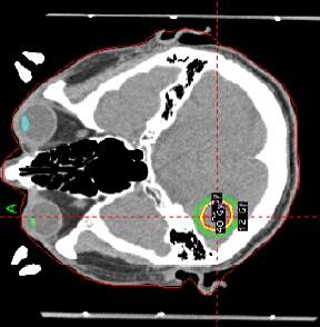


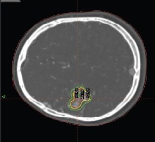


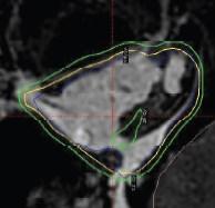
71 58 Figure 3.3 Study patients a) target locations on CT, b) target geometries on MRI. Red contours=gross tumor volume (GTV); yellow line=prescribed isodose. (a) (b)
72 Validation of the Margin Calculator - Results Phantom Study Results of the phantom validation are shown in Figure 3.4, including 64 points of M PTV comparison for each penumbra width tested. Of note, the linear fit (R 2 ) for the sphere with a 5.2 mm and 1.5 mm penumbra widths were R 2 =0.965 and R 2 =0.976, respectively, showing strong agreement and validation of the margin calculator tool. In the sphere with a 5.2 mm penumbra, the single fraction series had better agreement between the MvH predicted and calculated M PTV. The agreement within ± 0.2 mm was 100%, 31%, 19% and 25% for 1, 3, 5, and 10 fractions, respectively. The MvH formula predicted slightly higher margin requirements for the 3, 5, and 10 fraction series, with an average difference of 0.2 mm. All fractionations in the sphere with 1.5 mm penumbra had good agreement between the MvH and calculated M PTV. The agreement within ± 0.2 mm was 100%, 44%, 50% and 38% for 1, 3, 5, and 10 fractions, respectively.
73 60 Figure 3.4 Comparison of the planning target volume margins (M PTV ) predicted by known formula (MvH), and generated by the margin calculator (TMC) for 4 fractionation schedules (Fx). a) Comparison of sphere with 5.2 mm penumbra (R 2 = 0.965), and b) results of sphere with 1.5 mm penumbra (R 2 = 0.976). The black line represents perfect agreement. (a) (b)
74 Dose Scaling Approximation The M PTV-Additional was generated for 22 M PTVs across 10 patients. The median M PTV-Initial assessed was 3.2 mm (range mm). Eighty one percent (18/22) of the runs required an additional 0.2 mm margin. The 4 other targets required (0.4, 0.6, ) mm M PTV-Additional to ensure dosimetric coverage. This difference may be attributed to the difference in dose shape between automatic uniform scaling and clinical replans Patient Study A total of 640 M PTVs were calculated for 10 intracranial SRT patients over 4 fractionation schedules, encompassing 16 combinations of analytical systematic and random errors. Figure 3.5a compares the calculated margins to MvH results. A 73% agreement within ±1 mm was noted between the calculated and MvH M PTV, showing both larger and smaller margins when the published formula is used. The MvH formula generated larger M PTV requirements in 79.9% of the cases, had perfect agreement 12.4%, and smaller M PTV requirements in 7.7% of cases. One outlier patient was identified in the cohort, and their data points have been highlighted in purple. The source of this discrepancy is due to the concave nature of the target contour, affecting the reliability of the dose scaling algorithm. As such, for intracranial SRT where every small incremental increase affects the volume of tissue irradiated, the MvH formula may not be appropriate for use. Figure 3.5b represents patient data with the outlier patient removed. Figure 3.5c suggests that the MvH margin may be inadequate for lower fractionation schedules, in agreement with Herschtal et al. [72]. The agreement within ± 1 mm was 88%, 72%, 66% and 65% for 1, 3, 5, and 10 fractions, respectively. Figure 3.5d shows the effect of target size on M PTV requirements, where most targets show a margin requirement smaller than that of the MvH recipe. The agreement within ± 1 mm was 100%, 72%, 67% and 39% for < 1 cc, 1-5 cc, 5-10 cc, and > 10 cc, respectively. Very small targets (< 1 cc) are observed to agree with the MvH recipe results. This is in agreement with previous works of Witte et al., as the target size affects the shape of the penumbra, increasing the random error contribution to geometric uncertainty. [77]
75 62 The effect of target shape is pronounced in Figure 3.5e, where the margin calculator suggests that that a more irregularly shaped targets (ratio 1.8) also require a larger margin. The agreement within ± 1 mm was 62%, 74%, 100% and 74% for ratios of <1.2, , , and > 1.6, respectively. As previously discussed, on further investigation the concave shape of this outlier target affected the dose scaling algorithm, and the appropriate stretch in isotropic margin expansion was not observed. Other methods, such as dose dilation will have to be further explored to ensure the correct expansion of the dose perimeter. Figure 3.5 Comparison of the planning target volume margins (M PTV ) predicted by published formula (MvH), and generated by the margin calculator (TMC) for 10 intracranial SRT targets. Comparisons are shown for (a) all data points with the outlier patient represented in purple and (b) with the outlier patient removed. Comparisons without the outlier patient are shown for (c) fractionation (Fx) schedule, (d) target size, and (e) target shape through a surface area to volume ratio. The black line represents perfect agreement. (a)
76 63 (b) (c)
77 64 (d) (e)
78 Discussion As intracranial SRT has been shown to provide a high level of tumor control with minimal toxicity comparable to SRS [90], in combination with frameless immobilization systems and image-guidance, its use on the GK unit may increase [21, 86]. As such, determination of an optimal PTV margin is required. Although there are margin formulas in the literature, their limitation lies with their population-based nature, and large fractionation schedules these assumptions may be inappropriate for hypofractionation radiation therapy [54]. As such, an open source Margin Calculator has been developed and validated for hypofractionated radiation therapy. The calculator enables patientspecific M PTV generation for intracranial SRT through assessment of target shape and size, dose object characteristics, fractionation schedule, and treatment objectives. Treatment volumes are sensitive to small increases in M PTV, increasing the volume of normal brain receiving 12Gy, correlated to increased risk of radionecrosis [79]. As such, submillimeter precision may be required in a margin calculator. Accounting for the effects of lower fractionation schedules by using an effective systematic and random error in the MvH margin recipe resulted in larger margin requirements in 80% of the test cases [54, 58, 59]. Ultimately, as any M PTV addition will increase the treated volume, one commonly used clinical strategy is increasing the fractionation schedule, especially for larger intracranial targets. This allows blurring of the dose distribution, and is more forgiving of geometric uncertainties. The phantom sphere analysis was set up to match the assumptions of the published MvH formula; thus the agreement in results validated the calculator s performance. Differences were observed in the patient data as the assumptions related to target size and shape started to break down. This highlights that population-based margins may not be of optimal use in intracranial SRT where slight increases in margins have increasing risk of detrimental late side effects. The dose distribution in the margin calculator is rescaled, not recalculated, for the expanding M PTV, resulting in slightly different dose gradients compared to manually regenerated plans. In this work, assessment of the reliability of the scaled dose object and gradient was performed by comparison to manual replans, with an agreement of <1
79 66 mm. Adding a geometric margin and then re-planning loses the exact conformality of automatic dose scaling. Therefore, the M PTV suggested by calculator may represent a slight overestimation; future work will involve developing a factor to account for the difference between dosimetric and geometric margins, target shape, and risk of failure. The current margin calculator model minimizes the dose to normal tissues by generating the smallest M PTV that meets the treatment goal. Additionally, the M PTV is expanded isotropically, ignoring surrounding organs at risk or bony anatomy. The volume receiving V12 is also not considered, and thus, a secondary clinical assessment is required on the suggested M PTV especially in locations of the brain more at risk of symptomatic radionecrosis [15, 91]. In cases where the M PTV specified corresponds to a volume at high risk of radionecrosis, strategies such as increasing the fractionation schedule, or decreasing overall prescription dose could be employed. It was previously reported that simulated margins lose accuracy with very small targets [77]. In our study, we found very small targets (< 1cc) required relatively larger M PTV than their larger counterparts [54, 77]. With small targets, the ratio of the high dose region to the size of the uncertainty diminishes, resulting in higher sensitivities to increasing random uncertainties. Alternative strategies, such as the use of intensity scaling of the dose object, may be considered [92]. The margin calculator tool currently only accounts for translational uncertainties, negating results that may differ in the presence of rotations. One approach to this issue is to consider the calculated margin a lower limit, as rotational discrepancies will ultimately increase uncertainties [54]. Future work will focus on developing and validating rotational uncertainty modelling into the open source code. Finally, the margin calculator was developed using analytical random and systematic errors from a normal distribution. Actual clinical uncertainties may result in different values and application of patient based uncertainties, yielding different results. The next logical step is to use the calculator to generate PTV margins for inter- and intra-fraction errors characterized on a patient population.
80 Conclusions A process for the Margin Calculator has been developed and validated, and is useful in deriving patient-specific M PTV for intracranial GK SRT. The tool agrees well with published formula when used in scenarios that meets the underlying assumptions. The open source tool accounts for patient-specific target size and shape, dose object, and geometric uncertainties. Fractionation schedule and treatment goals can also be defined for an institution s specific needs. Use of the margin calculator provides evidence-based margins for the treatment target in intracranial SRT, enabling dose escalation while limiting radiation-induced toxicity to the patient.
81 68 Chapter 4 Impact of Immobilization on Intra-fraction Motion for Gamma Knife Stereotactic Radiosurgery Using Cone-Beam Computed Tomography This work will be presented in part at the 56 th Annual Meeting of American Society for Therapeutic Radiology and Oncology, Sept 14 th 17 th 2014, San Francisco, California. This chapter is being prepared for submission to the International Journal of Radiation Biology and Physics, with authorship of Winnie Li, Young-Bin Cho, Kyle Hiemstra, David A Jaffray, and Caroline Chung.
82 69 4 Impact of Immobilization on Intra-Fraction Motion for Gamma Knife Stereotactic Radiosurgery Using Cone- Beam Computed Tomography 4.1 Abstract Purpose/Objective(s): Intracranial stereotactic radiosurgery (SRS) relies on highly accurate positioning and immobilization to ensure accurate dose delivery. This study aims to utilize cone-beam computed tomography (CBCT) to measure geometric uncertainties associated with 2 immobilization systems used for SRS on Gamma Knife (GK). Materials/Methods: Using a novel CBCT system adapted to the GK radiosurgery treatment unit, CBCT images were acquired pre- and post-treatment for each fraction within the context of 2 ethics-approved prospective clinical trials. Patients were immobilized in either the rigid Leksell Coordinate Frame (LCF) or the extend relocatable head frame (RHF). The relative displacement of the patient s skull to the localizer box was measured for each CBCT. Differences between pre- and post-treatment CBCT images were used to assess intra-fraction motion. Results: A total of 26 pre- and 22 post-treatment CBCTs were analyzed in 22 patients: 20 LCF patients treated with single fraction SRS, and 2 patients treated using the RHF for fractionated SRS. The mean translational pre-treatment error ± standard deviation (SD) for 19 LCF patients in the left/right (LR), anterior/posterior (AP) and cranial/caudal (CC) directions were 0.21±0.32 mm, 0.05±0.27 mm, and -0.24±0.2 mm, respectively. One LCF patient had exceptionally large translational displacements of (0.12, 0.61, ) mm in the LR, AP and SI directions, respectively. The mean translational pretreatment error ± SD for the RHF in the LR, AP and CC directions were -0.22±0.27 mm, -0.93±0.87 mm, and 0.81±0.78 mm, respectively. The maximum rotation observed for the LCF was 0.87 and for the RHF, After an average time between pre- and post-treatment CBCT of 82:44 minutes (range 27:00 170:18), the mean intrafraction error ± SD for the LCF were ± 0.05 mm LR, ± 0.18 mm AP, ± 0.12 mm CC; for the RHF, 0.15 ± 0.23 mm LR, 0.10 ± 0.22 AP, and ± 0.35 mm CC.
83 70 Conclusion: Using a novel CBCT system on a GK radiosurgery treatment unit, the measured geometric uncertainties were generally smaller for the invasive frame than the relocatable frame for most data points. However, the presence of an outlier in the LCF cohort reinforces the need for online image-guidance prior to SRS delivery using both LCF and RHF immobilization. Although intra-fraction positional changes through a course of GK SRS are small, the larger set-up uncertainties (i.e. pre-treatment translational error) using the RHF supports the need for planning target volume margins for fractionated SRS. 4.2 Introduction Stereotactic radiosurgery (SRS) involves a single fraction of high dose radiation precisely focused on well-localized intracranial targets [9]. This technique is a less invasive alternative to surgery and is a well-established therapy for the management of metastatic intracranial diseases. The advantage of SRS is the rapid dose fall-off achieved by multiple beam directions and a high degree of collimation to spare normal tissues [10]. The ultimate goal of SRS is local control, with reported rates of 60-80% at 1 year [3]. Due to the risk of radiation necrosis, treatment for brain metastases is usually directed at patients with tumors less than 4 cm in maximum diameter as small increases in size affects the volume of normal brain receiving 12 Gy (V12) [14]. V12 is a predictor for radiation necrosis in intracranial tumors, and increase significantly if the volume for V12 is greater than 10 cm 3 [15]. To improve on the radiobiological therapeutic ratio, stereotactic radiotherapy (SRT) may be considered, a technique that delivers high dose radiation per treatment over a course of 2-5 fractions. The benefit of SRT over SRS is sparing of normal tissue by improving the radiobiological ratio while maintaining the benefits of high dose per fraction [17]. At our institution, single fraction SRS is delivered on the Gamma Knife Perfexion (GK- PFX), with patients immobilized in the rigid Leksell Coordinate Frame (LCF) [9]. A relocatable head frame (RHF) device, consisting of a patient specific dental bite block,
84 71 vacuum fixation, and customized head rest, is used for fractioned PFX-SRT [21, 85]. The RHF s precision for clinical use was determined in an ethics approved study on a linear accelerator with cone-beam computed tomography (CBCT) capabilities, reporting a 3-dimensional (3D) mean ± standard deviation (SD) setup accuracy of 1.3 ± 0.9 mm [21]. The clinical practice of GK-SRS does not utilize a planning target volume (PTV) margin around the intracranial gross tumor volume (GTV) [23, 24]. Reports of the use of PTV margin in the literature to account for geometric uncertainties are conflicting. Nataf et al found a 2 mm PTV margin was added for single fraction linac-srs resulted in a reported 12.5% increase in complications [74]. In another study by Choi et al, the addition of a 2 mm PTV margin to the resection cavity of brain metastases did not increase complication rates though 76% of the patient cohort with a margin added had SRS delivered over a 3 day schedule [75]. Noel et al found a 1 mm PTV margin for SRS improved local control, but did not influence complication rates [73]. With the use of SRT for frameless immobilization, the addition of an optimal PTV margin is required to increase treatment accuracy while limiting toxicity. A novel cone-beam computed tomography (CBCT) capable device has been developed, installed and commissioned at our institution on the PFX unit to facilitate image-guided radiation therapy (IGRT) [86]. Through the acquisition of volumetric images of the patient in the treatment position, a comparison can be made to the planning CT to ensure optimal accuracy. Patient setup geometric uncertainties in 3D can be measured and corrected prior to treatment delivery. Evidence-based uncertainties would optimize the PTV margin used, improving the therapeutic ratio. The purpose of this study was to quantify inter- and intra-fraction uncertainties for brain metastases patients receiving PFX-SRS or PFX-SRT with either the LCF or RHF through CBCT imaging. Quantification of uncertainties will enable evidence-based planning target volume margins for brain metastases patients undergoing treatment with single or multi-fraction SRS.
85 Methods & Materials Patients and Treatment Planning Informed consent was required for participation in this research ethics board approved prospective study. Study participants included 22 patients treated from September 2011 to November 2013 on the GK-PFX. Patients were immobilized supine for simulation and treatment planning in one of two devices. The rigid LCF (Elekta Instruments, Stockholm, Sweden) facilitated single fraction treatment (see Figure 1.2). The extend RHF (Elekta Instruments, Stockholm, Sweden) was utilized for fractionated SRT (see Figure 1.3a) [21]. The fractionation schedules used at our institution range from Gy delivered in a single fraction, to 24 Gy delivered in 3 fractions. A summary of patient and treatment characteristics is provided in Table 4.1. Table 4.1 Patient and treatment characteristics Patients n = 22 Targets n = 40 Immobilization Leksell Coordinate Frame n = 20 Relocatable Head Fame n = 2 Gender Male n = 9 Female n = 13 Dose/Fractionation Gy/1 n = Gy/3 n = 2 Briefly, for treatment planning, all patients underwent a gadolinium enhanced contrast volumetric magnetic resonance imaging (1 mm axial T1 and T2 fluid attenuated inversion recovery images) for target (i.e. GTV) delineation and CT simulation (1 mm
86 73 slice thickness) for treatment planning. For single fraction SRS, no PTV margin was added to the GTV. For fractionated SRT, a 1.5 mm PTV margin was added to the GTV in the left/right (LR) and anterior/posterior (AP) axes, while a 2 mm PTV margin was added in the cranial/caudal (CC) direction. All patients were planned using the gamma knife treatment planning system (Leksell Gamma Plan version 10.1, Elekta Stockholm, Sweden), utilizing 192 cobalt-60 beamlets (i.e. shots) to generate conformal treatment plans with steep dose drop-offs Image-guidance Patients were treated on the GK-PFX (Elekta, Stockholm, Sweden), equipped with a CBCT image guidance unit (see Figure 4.1) [86]. The CBCT scans were acquired with a bow-tie filter over a gantry rotation of 210, with a scan time of 70 seconds and projection rate of 3 frames-per-second. The imaging technique used for CBCT imaging was 90 kvp, 20 ma, and 25 ms, corresponding to a dose of 1.2 cgy measured at the center of a 16 cm cylindrical phantom [86]. The clinical workflow for CBCT acquisition with Image-guided Perfexion (IGP) is outlined in Figure 4.2. After patient docking/positioning on the GK-PFX bed, the IGP device was lowered from its parked position to enable volumetric imaging [86]. A pretreatment CBCT was acquired, and assessed visually to ensure there are no large discrepancies compared to the reference CT image (i.e. > 5 mm). The current research prototype of the system does not enable online registration and fusion of the CBCT to the CT image, thus only visual inspection was used. At the end of treatment, a posttreatment CBCT was acquired with the patient in the treated position. Both CBCT scans were exported to the treatment planning system (Leksell Gamma Plan version 10, Elekta, Stockholm, Sweden) for offline assessment.
 Before: as commercially available, b) After: with the")

87 74 Figure 4.1 The Gamma Knife Perfexion unit. a) Before: as commercially available, b) After: with the installation of the Image-Guided Perfexion device to enable cone-beam computed tomography imaging. The red arrow is pointing to the x-ray tube. (a) (b)
88 75 Figure 4.2 Clinical Workflow for CBCT acquisition using Image-Guided Perfexion. Abbreviations: CBCT = cone beam CT; TPS = treatment planning system. Prepare patient study in image acquisition software Set up patient in immobilization device on treatment couch Move treatment couch to CBCT acquisition position Deploy CBCT system vertical Rotate imaging arm to startof-scan Acquire CBCT using clinical preset Online: Visual comparison of CBCT with published plan Park CBCT System Treat Offline: Export images to TPS for assessment Data Collection All patients pre- and post-treatment CBCTs were exported to the treatment planning system for offline assessment. The relative displacement of the patient s skull to the N-
89 76 localizer box was determined through image fusion (Leksell Gamma Plan version 10, Elekta Stockholm, Sweden) by a single experienced observer. The N-localizer box is a device attached to the immobilization device that allows spatial orientation of the patient to stereotactic space. Regions of interest (i.e. bounding clipbox) were used for automatic fusion to the localizer frame and bony anatomy. The bounding clipbox used for automatic image registration of bony anatomy included the rigid skull, and mobile regions, such as the mandible, were excluded for the match. Data processing of image fusion was performed using a commercial software package (MATLAB 8.1, The MathWorks Inc., Natick, MA). The setup (i.e. inter-fraction) error was determined by the pre-treatment CBCT, noting the difference in automatic registration between patient bony anatomy and the localizer frame. Setup differences observed between pre- and post-treatment CBCT images were used to quantify intra-fraction motion. Patient translational positioning discrepancies, maximum rotation, and image acquisition time stamps were recorded for each CBCT. The group mean and standard deviation (SD) were calculated for each immobilization system in the left-right (LR), anterior-posterior (AP), and cranial-caudal (CC) directions. 4.4 Results A total of 26 pre- and 22 post-treatment CBCTs were analyzed in 22 patients: 20 LCF patients treated with single fraction SRS, and 2 patients treated using the RHF for fractionated SRT. For all patients, the average time between pre- and post-treatment CBCT acquisition was 82 minutes (range minutes). Summary statistics for both immobilization systems are presented in Table 4.2. The average time between pre- and post-treatment CBCT for the LCF patients was 82 minutes (range ). The setup error measured with the LCF patients on the pretreatment CBCTs were small. The mean translational setup error ± SD for 19 LCF patients in the LR, AP and CC directions were 0.21±0.32 mm, 0.05±0.27 mm, and ±0.2 mm, respectively. However, one LCF patient had exceptionally large translational displacements of 0.12 mm, 0.61 mm, mm in the LR, AP and CC
90 77 directions, respectively (see Figure 4.3). This may be indicative of frame slippage. The maximum rotation noted for the LCF device was In the RHF cohort, the average time between pre- and post-treatment CBCT was 83 minutes (range 66 92).The mean translational pre-treatment error ± SD for the RHF in the LR, AP and SI directions were -0.22±0.27 mm, -0.93±0.87 mm, and 0.81±0.78 mm, respectively. The maximum rotation observed for the RHF was Both the translational and rotational discrepanies, while small, were larger than that noted with the rigid LCF device. The intra-fraction error was quantified as the difference noted between the pre- and post-treatment CBCT scans. Both immobilization systems reported submillimeter movement during treatment. The mean intrafraction error ± SD for the LCF were ± 0.05 mm LR, ± 0.18 mm AP, ± 0.12 mm CC. The mean intrafraction error ± SD for the RHF were larger at 0.15 ± 0.23 mm LR, 0.10 ± 0.22 AP, and ± 0.35 mm CC. Table 4.2 Summary statistics for setup/inter-fraction error and intra-fraction error for the Leksell Coordinate Frame (LCF) and Relocatable Head Frame (RHF) immobilization devices. Abbreviations: LR = left/right, AP = anterior/posterior, CC= cranial/caudal, SD = standard deviation Immobilization Setup Error (mm) Intra-fraction Error (mm) LR AP CC LR AP CC LCF Mean n = 20 SD LCF - No Outlier Mean n = 19 SD RHF Mean n = 2 SD


 Patient bony anatomy is aligned with the bounding box (light blue), but a")
 Localizer frame is aligned with the bounding box, but the patient bony")
91 78 Figure 4.3 Pre-treatment CBCT registration of the outlier patient from the Leksell Coordinate Frame cohort. The blended overlay shows the reference CT in purple, CBCT in green, and perfect alignment displayed as white. a) Patient bony anatomy is aligned with the bounding box (light blue), but a discrepancy is noted with the localizer frame. b) Localizer frame is aligned with the bounding box, but the patient bony anatomy shows a discrepancy in the cranial/caudal (CC) direction. (a) Bony Anatomy (b) Localizer Localizer Bony Anatomy Localizer frame misaligned ~2 mm in CC axis Bony anatomy misaligned ~ 2 mm in CC axis
92 Discussion A CBCT image-guidance system for PFX was developed and clinically implemented at our institution [86]. Early results validated the system s capability of intracranial imaging, ensuring the system enabled precise and accurate targeting for fractionated and single-fraction radiosurgery through bony anatomy registration [86], which has previously been shown to be a reliable surrogate for target position of brain metastases [43]. The advantage of 3D image-guidance is that it decreases user subjectivity and inter-observer variation in image assessment and changes in patient anatomy is more easily visualized and assessed. This study presents the first series of patient images acquired from the Image-guided Perfexion (IGP) platform, characterizing this patient population s inter- and intra-fraction uncertainties. The IGP device enabled quantification of setup errors associated with the rigid LCF frame through volumetric imaging. The setup errors reported of < 1 mm is in agreement with previous rigid frame measurements performed with 2D kilovoltage radiographs [19, 37]. An outlier patient was identified in the LCF group, showing a discrepancy of ~2 mm in the CC direction on both the pre- and post-treatment CBCT. As SRS patients at our institution are presently planned with a 0 mm PTV margin around the GTV, this magnitude of setup discrepancy constitutes a geographic miss. Frame slippage is an issue that has been previously identified, as any motion of the frame relative to the patient s anatomy would result in a misalignment of the radiation and target [20]. Furthermore, it has been demonstrated that despite the invasiveness of the rigid frame, some degree of motion is still measurable with stress loading [39]. The presence of the outlier in the study cohort further reinforces the need for image-guidance prior to SRS even with the LCF. One of the main limitations of this analysis is that only 2 patients were included in the RHF cohort to assess setup error for this population of patients. Despite a small number of patients, the inter- and intra-fraction data measured for the RHF device with the IGP was consistent with the previous measurements from the linac study using 14 patients [21]. It is not surprising that the setup error on the frameless immobilization system is larger than that noted with the rigid frame. As the characterization of the uncertainties
93 80 associated with this device was previously collected on the linac study, a PTV margin was designed and clinically used to account for these geometric offsets, reducing the risk of a geographic miss. Submillimeter intra-fraction uncertainties were noted with both immobilization devices, with longer treatment times experienced by the LCF patients. At the time of this investigation, the Cobalt-60 source of the PFX unit had reached its half-life, and was due for a source change. Despite the long treatment times, the volumetric images validate patients do not move much during treatment in either device, allowing for accurate treatment. It is important to note that pre- and post-treatment CBCTs do not monitor intra-fraction during treatment; other strategies, such as passive optical tracking may be an effective strategy for intra-fraction motion management for SRS/SRT [93]. IGP is currently used as a research tool, with assessment of CBCT images performed offline [86]. Integration of this technology for use in the online environment would require additional considerations, as treatment delivery on PFX is performed with multiple shots and isocenters, and couch positions are directly transferred from the planning system to the treatment console. This differs from the linear accelerator setting, where usually a single isocenter is used to treat the entire target. Discrepancies noted on the CBCT image may warrant dose re-computation and further investigation in the treatment planning system prior to displacement corrections and subsequent SRS/SRT delivery. Ensuring appropriate PTV margins around the treatment volume ensures adequate treatment of the target while limiting radiation-induced toxicity to the patient [79]. Characterization of geometric uncertainties associated with various immobilization devices on IGP allows generation of population based PTV margins. Identification and correction of inter-fraction uncertainties through online CBCT for SRT reduces the margin requirement for geometric errors [21]. PTV margin formulas in the literature are associated with assumptions that are not readily applicable to intracranial SRT tumors [54]. Recent work on a margin calculator aims to optimize PTV margins specifically for intracranial SRS/SRT, and can be utilized to compute rational margins for PFX treatment [94]. Preliminary test results using the calculator resulted in PTV margins for a
94 81 LCF patient undergoing SRS at (0.6, 0.6, 0.4) mm in the LR, AP, and CC directions, respectively. Larger margins of (0.4, 1.8, 1.6) mm in the LR, AP, and CC directions, respectively, were required for the RHF at a 3 fraction SRT schedule. 4.6 Conclusion Using a novel CBCT system on the GK radiosurgery treatment unit, the measured geometric uncertainties were generally smaller for the invasive frame than the relocatable frame for most data points. However, the presence of an outlier in the LCF cohort reinforces the need for online image-guidance prior to SRS delivery using both LCF and RHF immobilization. Although intra-fraction positional changes through a course of GK SRS are small, the larger set-up uncertainties (i.e. pre-treatment translational error) using the RHF supports the need for planning target volume margins for fractionated SRS.
95 Chapter 5 General Discussion and Future Directions 82
96 83 5 General Discussion and Future Directions 5.1 General Discussion The incidence of brain metastases is common and their impact on patients can be debilitating [95]. There is a changing landscape in the methods of treating this patient population. Traditionally whole brain radiation therapy was used, but it is associated with decreased neurocognitive function and poor quality of life. As such, targeting the tumors themselves within the brain through stereotactic radiosurgery (SRS) has increased in popularity, as surrounding normal tissues so not receive as much dose. The use of single fraction SRS is limited by target number and size, and there is increasing reliance on fractionated stereotactic radiotherapy (SRT). Novel techniques in frameless intracranial SRT are being investigated to improve treatment outcomes and quality of life. To ensure adequate target coverage in SRT, a planning target volume (PTV) margin must be added to the clinical target volume to allow for inter- and intrafraction uncertainties associated with frameless systems. The geometric PTV margin around an intracranial target is designed to account for systematic and random uncertainties. As margin requirements increase, other patient factors related to toxicity should be carefully considered. Basic principles of the effect of PTV margin expansions from a treatment target were discussed in Chapter 2. Adding a PTV margin causes an increase in the treated volume in a linear fashion. Increasing the treated volume subsequently increases the volume that receives 12 Gy (V12), associated with risk of radionecrosis. Radiation necrosis is a late side effect of radiation, and its clinical presentation differs depending on the location it presents in, and can cause memory loss and decreased motor functions. Prescribing to a higher isodose reduced overall treatment times, improving patient comfort but caused a small increase in V12. A balance between the need for a PTV margin to ensure adequate dose to the target and the potential detrimental increase in toxicity this increased treated volume may have on the patient should be carefully considered. PTV margin formulas in the literature are based upon generalized assumptions and that may not be applicable to SRT [48, 71, 72]. The methods used in applying margins in
97 84 SRT are associated with various assumptions not readily applicable to hypofractionated schedules [54]. These population based margins formulas may not be optimal for SRT as they are associated with large fractionation schedules, and conformal dose distributions. The ability to calculate rational PTV margins for short fraction schedules with stereotactic dose distribution have the potential to optimize the therapeutic ratio for intracranial SRT patients. In Chapter 3, a tool was developed and validated to derive rational PTV margins with assumptions that hold for Gamma Knife (GK) SRT. From the validation assessment, the phantom sphere experiment showed congruence between the published formula and calculated margins as the assumptions of the formula were met. However, for patient data, when compared to the margin calculator, the generic population based van Herk margin formula generated larger PTV margin requirements in ~80% of cases, even after accounting for the effects of low fractionation schedules [54, 58, 59, 67]. This is important to consider as incremental expansion of the PTV margin have a positive correlation to the V12 volume, increasing the risk of radionecrosis [15, 79]. For larger targets, a PTV margin addition of any magnitude increased the treated volume substantially. Thus, alternative strategies such as increasing fractionation or prescribing the target to a lower dose should be explored in the clinical environment [79]. The validation of the margin calculator was performed with analytically selected random and systematic uncertainties, a limitation of the study. Chapter 4 quantified the inter- and intra-fraction uncertainties for 2 immobilization devices used for GK SRS and SRT. Using a novel cone-beam CT (CBCT) system on the GK radiosurgery treatment unit, the measured geometric uncertainties were generally smaller for the invasive Leksell Coordinate Frame (LCF) than the Relocatable Head Frame (RHF). However, the presence of an outlier in the LCF cohort reinforced the need for online image-guidance prior to SRS delivery using both LCF and RHF immobilization. Although intra-fraction positional changes through a course of GK SRS are small, the magnitude of set-up uncertainties (i.e. pre-treatment translational error) using the RHF supports the need for planning target volume margins for fractionated SRT.
98 Clinical Implementation Clinical implementation of the margin calculator tool for intracranial SRT is the next logical step from this work. Preliminary test results were presented at the end of Chapter 4; appropriate quality assurance tests are required prior to full implementation in the clinic. Measuring and identification of systematic and random errors associated with other immobilization devices would serve as inputs into the calculator. Geometric uncertainties of the RHF have previously been measured from linac studies, and could be readily applied [21, 85]. Other devices, such as thermoplastic mask systems, are used for SRS and SRT, and could rival the precision and accuracy of rigid frame immobilization systems when combined with image guidance [41, 50]. Use of CBCT on GK Perfexion for SRT allows online visualization of patient anatomy prior to treatment delivery, further enabling identification and correction of systematic and random setup errors [86]. In the near future, online assessment of pre- and post-treatment CBCTs will validate the stability and reproducibility of various immobilization strategies. These measured uncertainties can be fed into the margin calculator, along with patient-specific parameters, to generate PTV margins that will ensure the safe use of the relocatable system by decreasing the risk of geographic misses. Clinical implementation of the margin calculator will impact the treatment and margin design for patients undergoing SRT for brain metastases, potentially improving local control by ensuring the target receives the prescribed dose. Our investigation has shown that population based margins are too generous for intracranial targets the use of personalized PTVs decreases the amount of normal tissues irradiated. Additionally, the volume at risk of developing radiation necrosis also decreased. Ensuring appropriate margins around the treatment volume limits radiation-induced toxicity to the patient, potentially improving the therapeutic ratio, and increasing the patient s quality of life.
99 Future Directions A margin calculator was developed and validated for translational discrepancies in intracranial stereotactic radiation therapy. As intracranial targets are generally spherical in nature, correction of translational errors may be sufficient to ensure adequate dose delivery to the target. To make the calculator more robust, and increase its applicability to other treatment sites, various modules can be created and added in the future to improve functionality and applicability: 1) The testing criteria used for the margin calculator was limited to intracranial SRS targets from the GK system, 4 hypofractionation schedules, and geometric uncertainties with an upper limit of 1.5 mm. This corresponds to an approximate upper limit of 5 mm PTV margin in most patient scenarios tested. As the margin calculator module was developed in open source code, the tool can be modified and individually validated for other systems such as linear accelerator treatment planning systems [88]. 2) The margin calculator currently accounts for translational uncertainties only, negating results that may differ in the presence of rotations. One approach to this issue is to consider the calculated margin a lower limit, as rotational discrepancies will ultimately increase uncertainties [54, 96]. Figure 5.1 illustrates the effect of rotational displacements on target coverage and impact on surrounding organs at risk. While targets are generally spherical and will be minimally impacted from rotations, surrounding organs at risk will be increasingly affected by the presence of larger rotations. Future work will focus on developing and validating rotational uncertainty modelling into the open source code [97]. 3) The uncertainty distributions were modeled in a Gaussian fashion in accordance with assumptions of the central limit theorem. Other uncertainty distributions, such as sinusoidal or bimodal could be programmed into the calculator tool, depending on the population and motion of interest. Additionally, the Gaussian distribution could possibly be truncated at 2 standard deviations in the era of
100 87 IGRT where large patient setup displacements are rare and efficiently corrected with daily volumetric imaging. 4) The margin calculator could be validated and used for different sites, especially in areas that treat stereotactic body radiation therapy (SBRT). For use on the paraspinal patient cohort, the tool would have to not only optimize for the PTV margin, but also the margin on surround organs at risk [69]. Motion management and incorporation of internal target volume margin concepts would need to be programmed for use in SBRT lung and liver patients [68]. 5) The margin calculator uses image scaling as a method of dose morphology to allow automatic uniform expansion of the dose object, mimicking the effect of increasing PTV margins. The algorithm resizes an image by stretching the dose object, applying interpolation from the center of the mass. Though the reliability of this stretch on the dose gradient was validated in Chapter 3, other methods of dose morphology may be considered. The use of dose dilation using a kernel would grow a dose object without changing the dose gradient. The disadvantage to this method is that the kernel size used is dependent on the voxel size of an image. To grow margins by 0.2 mm increments, an image with a 1 mm voxel size would have to be up-sampled, resulting in longer time required when growing an image. Other novel and more complex methods of changing and growing the dose object through deformable registration could also be explored [98].
101 Figure 5.1 Impact of rotational discrepancies on targets and surrounding organs at risk. a) The cone-beam CT (CBCT) image presents both translational and rotational offsets with respect to the gross tumor volume (GTV) in the reference CT image. b) Image registration is performed automatically with 6 degrees-of-freedom. Both translational and rotational offsets are registered in this match. c) Correction of translational discrepancies only, resulting in a best fit of the GTV. Depending on the rotational offset measured, the relative position of the organs at risk (OAR) may be suboptimal. 88
102 89 The radiation therapy adaptation agenda has been defined as a feedback control strategy to include patient-specific treatment variation explicitly in the control of treatment planning and delivery during the treatment course [99]. Incorporation and clinical implementation the margin calculator into the adaptive radiation therapy loop would increase its use and potential, as patient specific PTV margins allow dose escalation and/or toxicity reduction [100]. It was already shown in Chapter 3 that the margin calculator generated smaller PTV margin requirements then the generic population-based margin formula. Figure 5.2 compares the current workflow of radiation therapy delivery, to a potentially new workflow in the near future. The current workflow corrects identifies and corrects any online setup uncertainties, but the information is not fed back into the treatment plan. The adaptive process monitors the daily setup variation of the patient, and allows modification of the delivered plan to ensure clinical goals are met. Ultimately, this will allow for the use of a smaller margin as any translational uncertainties would be corrected, and PTV margins would only need to account for the residual errors. There are limitations to adaptation, as methods to track delivered doses is still a novel and challenging goal, plan re-optimization takes time, and current solutions may not yet be ready for prime time use. However, in conjunction with deformable registration [101] and dose accumulation tools [102], adapting treatment with smaller margins noted by imaging during treatment will ultimately improve the therapeutic ratio.
103 90 Figure 5.2 Comparison of (a) current conventional workflow for radiation therapy, and (b) proposed workflow incorporating the use of the planning target volume margin calculator. The adaptive process outlined in workflow (b) incorporates the use of individualized margins of the day, sparing normal surrounding tissues while ensuring the target receives prescribed radiation dose. a) Patient b) Consent Patient Consent Simulation Simulation Planning Population-based PTV Margins Planning Population-based PTV Margins Online Treatment Imaging Apply online corrections Treatment Online Treatment Imaging Quantify residual geometric uncertainties PTV Margin Calculator Determine optimal margin based on residual uncertainties Re-optimize Plan 1) Use new PTV margins 2) Track delivered dose No Population-based PTV margin represent the uncertainties of the day? Yes Treatment

 have reported a positive correlation between increased patient motion and time on the treatment bed [103, 104], measuring this uncertainty for")
104 91 Intra-fraction motion management for any immobilization device used on the GK unit is useful for measuring any potential drift experienced by patients receiving SRS or SRT. As the source half-life approaches, treatment on cobalt units increases, and treatments that used to take 30 minutes will eventually require 60 minutes to complete. As other stereotactic treatment sites (i.e. lung and spine) have reported a positive correlation between increased patient motion and time on the treatment bed [103, 104], measuring this uncertainty for intracranial patients is also important. The use of an optical tracking system for patient monitoring could be useful as passive markers placed both on the patient and immobilization device can be tracked by infrared light [105]. Figure 5.3 shows the setup of a current study underway at our institution, to assess the reliability of optical tracking of an infrared nose marker as a measure of intra-fraction motion. The information gained by passive monitoring would supplement the uncertainty data obtained through pre- and post-treatment CBCTs and allow incorporation of intra-fraction uncertainties into the margin calculation. The study will also assess the nose tip as a reliable surrogate point of monitoring motion any movement detected will be compared to bony anatomy registration on the CBCTs. Figure 5.3 (a) Thermoplastic mask immobilization for a metastatic brain patient, with the nose portion cut-out. A reflective marker is placed on the patient s nose to enable infrared tracking. (b) In-room setup of a patient undergoing linear accelerator treatment for brain metastases. The optical camera highlighted with a red arrow monitors any movement. (a) (b)
Image Fusion, Contouring, and Margins in SRS
 Image Fusion, Contouring, and Margins in SRS Sarah Geneser, Ph.D. Department of Radiation Oncology University of California, San Francisco Overview Review SRS uncertainties due to: image registration contouring
Stereotactic Radiosurgery. Extracranial Stereotactic Radiosurgery. Linear accelerators. Basic technique. Indications of SRS
 Stereotactic Radiosurgery Extracranial Stereotactic Radiosurgery Annette Quinn, MSN, RN Program Manager, University of Pittsburgh Medical Center Using stereotactic techniques, give a lethal dose of ionizing
Linac or Non-Linac Demystifying And Decoding The Physics Of SBRT/SABR
 Linac or Non-Linac Demystifying And Decoding The Physics Of SBRT/SABR PhD, FAAPM, FACR, FASTRO Department of Radiation Oncology Indiana University School of Medicine Indianapolis, IN, USA Indra J. Das,
A Patient s Guide to SRS
 A Patient s Guide to SRS Stereotactic Radiosurgery 230 Nebraska St. Sioux City, IA 51101 NOTES 230 Nebraska St. Sioux City, IA 51101 Contents page Introduction 1 SRS and how it works 2 The technology involved
Chapters from Clinical Oncology
 Chapters from Clinical Oncology Lecture notes University of Szeged Faculty of Medicine Department of Oncotherapy 2012. 1 RADIOTHERAPY Technical aspects Dr. Elemér Szil Introduction There are three possibilities
Work partially supported by VisionRT
 Work partially supported by VisionRT Background of frameless intracranial stereotactic radiosurgery UCSD SRS/SRT procedure Clinical Results Summary Total prescribed doses : order of 10 50 Gy Planning targets
UNIVERSITY OF WISCONSIN-LA CROSSE Graduate Studies
 UNIVERSITY OF WISCONSIN-LA CROSSE Graduate Studies A SINGLE INSTITUTION S EXPERIENCE IN DEVELOPING A PURPOSEFUL AND EFFICIENT OFF-LINE TECHNIQUE FOR ADAPTIVE RADIOTHERAPY IN A CLINICAL ENVIRONMENT A Research
Radiosurgery. Most Important! 8/2/2012. Stereotactic Radiosurgery: State of the Art Technology and Implementation Linear Accelerator Radiosurgery
 Therapy SAM Symposium: WE-A-BRCD-1 Stereotactic Radiosurgery: State of the Art Technology and Implementation Linear Accelerator Radiosurgery Kamil M. Yenice, PhD Associate Professor Chief of Clinical Physics
Leksell Gamma Knife Icon A New User s Perspective
 Leksell Gamma Knife Icon A New User s Perspective Steve Herchko, DMP 2017 MFMER slide-1 Disclosures None 2017 MFMER slide-2 Outline Icon Overview Mayo Clinic Experience Frame-Based System Mask-Based System
SRS Uncertainty: Linac and CyberKnife Uncertainties
 SRS Uncertainty: Linac and CyberKnife Uncertainties Sonja Dieterich, PhD Linac/CyberKnife Technological Uncertainties 1 Linac Mechanical/Radiation Isocenters Depuydt, Tom, et al. "Computer aided analysis
Leksell Gamma Knife Icon. Treatment information
 Leksell Gamma Knife Icon Treatment information You may be feeling frightened or overwhelmed by your recent diagnosis. It can be confusing trying to process a diagnosis, understand a new and challenging
Strategies and Technologies for Cranial Radiosurgery Planning: Gamma Knife
 Conflicts of Interest Strategies and Technologies for Cranial Radiosurgery Planning: Gamma Knife David Schlesinger, Ph.D. Research support: Elekta Instruments, AB Lars Leksell Gamma Knife Center University
Evaluation of Monaco treatment planning system for hypofractionated stereotactic volumetric arc radiotherapy of multiple brain metastases
 Evaluation of Monaco treatment planning system for hypofractionated stereotactic volumetric arc radiotherapy of multiple brain metastases CASE STUDY Institution: Odette Cancer Centre Location: Sunnybrook
Overview of MLC-based Linac Radiosurgery
 SRT I: Comparison of SRT Techniques 1 Overview of MLC-based Linac Radiosurgery Grace Gwe-Ya Kim, Ph.D. DABR 2 MLC based Linac SRS Better conformity for irregular target Improved dose homogeneity inside
Can we hit the target? Can we put the dose where we want it? Quality Assurance in Stereotactic Radiosurgery and Fractionated Stereotactic Radiotherapy
 Quality Assurance in Stereotactic Radiosurgery and Fractionated Stereotactic Radiotherapy David Shepard, Ph.D. Swedish Cancer Institute Seattle, WA Timothy D. Solberg, Ph.D. University of Texas Southwestern
Intensity modulated radiotherapy (IMRT) for treatment of post-operative high grade glioma in the right parietal region of brain
 for treatment of post-operative high grade glioma in the right parietal region of brain") 1 Carol Boyd March Case Study March 11, 2013 Intensity modulated radiotherapy (IMRT) for treatment of post-operative high grade glioma in the right parietal region of brain History of Present Illness:
1 Carol Boyd March Case Study March 11, 2013 Intensity modulated radiotherapy (IMRT) for treatment of post-operative high grade glioma in the right parietal region of brain History of Present Illness:
Unrivaled, End-to-End
 PHANTOMS Unrivaled, End-to-End Stereotactic QA Industry-leading 0.1mm accuracy minimizes errors at each link in the stereotactic quality assurance chain. Stereotactic radiosurgery (SRS) is governed by
Feasibility of 4D IMRT Delivery for Hypofractionated High Dose Partial Prostate Treatments
 Feasibility of 4D IMRT Delivery for Hypofractionated High Dose Partial Prostate Treatments R.A. Price Jr., Ph.D., J. Li, Ph.D., A. Pollack, M.D., Ph.D.*, L. Jin, Ph.D., E. Horwitz, M.D., M. Buyyounouski,
Radiosurgery by Leksell gamma knife. Josef Novotny, Na Homolce Hospital, Prague
 Radiosurgery by Leksell gamma knife Josef Novotny, Na Homolce Hospital, Prague Radiosurgery - Definition Professor Lars Leksell The tools used by the surgeon must be adapted to the task and where the human
Evaluation of Whole-Field and Split-Field Intensity Modulation Radiation Therapy (IMRT) Techniques in Head and Neck Cancer
 Techniques in Head and Neck Cancer") 1 Charles Poole April Case Study April 30, 2012 Evaluation of Whole-Field and Split-Field Intensity Modulation Radiation Therapy (IMRT) Techniques in Head and Neck Cancer Abstract: Introduction: This study
1 Charles Poole April Case Study April 30, 2012 Evaluation of Whole-Field and Split-Field Intensity Modulation Radiation Therapy (IMRT) Techniques in Head and Neck Cancer Abstract: Introduction: This study
IGRT Protocol Design and Informed Margins. Conflict of Interest. Outline 7/7/2017. DJ Vile, PhD. I have no conflict of interest to disclose
 IGRT Protocol Design and Informed Margins DJ Vile, PhD Conflict of Interest I have no conflict of interest to disclose Outline Overview and definitions Quantification of motion Influences on margin selection
Changing Paradigms in Radiotherapy
 Changing Paradigms in Radiotherapy Marco van Vulpen, MD, PhD Mouldroomdag-2015 Towards the elimination of invasion 1 NIH opinion on the future of oncology Twenty-five years from now,i hope that we won
Stereotaxy. Outlines. Establishing SBRT Program: Physics & Dosimetry. SBRT - Simulation. Body Localizer. Sim. Sim. Sim. Stereotaxy?
 Establishing SBRT Program: Physics & Dosimetry Lu Wang, Ph.D. Radiation Oncology Department Fox Chase Cancer Center Outlines Illustrate the difference between SBRT vs. CRT Introduce the major procedures
Image Guided Stereotactic Radiotherapy of the Lung
 Image Guided Stereotactic Radiotherapy of the Lung Jamie Marie Harris, MS DABR Avera McKennan Radiation Oncology September 25, 2015 Stereotactic Body Radiotherapy - Clinical Dose/Fractionation - Normal
Let s speak the same language: Standardization in Terminology
 Faculty Disclosure Let s speak the same language: Standardization in Terminology Michael Torrens Gamma Knife Department, Hygeia Hospital, Athens, Greece Why is standardization necessary? Neurosurgical
8/3/2016. Outline. Site Specific IGRT Considerations for Clinical Imaging Protocols. Krishni Wijesooriya, PhD University of Virginia
 Site Specific IGRT Considerations for Clinical Imaging Protocols Krishni Wijesooriya, PhD University of Virginia Outline Image registration accuracies for different modalities What imaging modality best
Institute of Oncology & Radiobiology. Havana, Cuba. INOR
 Institute of Oncology & Radiobiology. Havana, Cuba. INOR 1 Transition from 2-D 2 D to 3-D 3 D conformal radiotherapy in high grade gliomas: : our experience in Cuba Chon. I, MD - Chi. D, MD - Alert.J,
Implementing New Technologies for Stereotactic Radiosurgery and Stereotactic Body Radiation Therapy
 Implementing New Technologies for Stereotactic Radiosurgery and Stereotactic Body Radiation Therapy Implementation of radiosurgery and SBRT requires a fundamentally sound approach Errors don t blur out
EXACTRAC HIGHLY ACCURATE PATIENT MONITORING
 EXACTRAC HIGHLY ACCURATE PATIENT MONITORING PATIENT POSITION MONITORING ExacTrac is an in-room based monitoring system that detects intrafractional motion during treatment delivery. Two kv X-Ray units
IMRT/IGRT Patient Treatment: A Community Hospital Experience. Charles M. Able, Assistant Professor
 IMRT/IGRT Patient Treatment: A Community Hospital Experience Charles M. Able, Assistant Professor Disclosures I have no research support or financial interest to disclose. Learning Objectives 1. Review
Herlev radiation oncology team explains what MRI can bring
 Publication for the Philips MRI Community Issue 46 2012/2 Herlev radiation oncology team explains what MRI can bring The radiotherapy unit at Herlev University Hospital investigates use of MRI for radiotherapy
Treatment Planning Evaluation of Volumetric Modulated Arc Therapy (VMAT) for Craniospinal Irradiation (CSI)
 for Craniospinal Irradiation (CSI)") Treatment Planning Evaluation of Volumetric Modulated Arc Therapy (VMAT) for Craniospinal Irradiation (CSI) Tagreed AL-ALAWI Medical Physicist King Abdullah Medical City- Jeddah Aim 1. Simplify and standardize
Treatment Planning Evaluation of Volumetric Modulated Arc Therapy (VMAT) for Craniospinal Irradiation (CSI) Tagreed AL-ALAWI Medical Physicist King Abdullah Medical City- Jeddah Aim 1. Simplify and standardize
IGRT Solution for the Living Patient and the Dynamic Treatment Problem
 IGRT Solution for the Living Patient and the Dynamic Treatment Problem Lei Dong, Ph.D. Associate Professor Dept. of Radiation Physics University of Texas M. D. Anderson Cancer Center Houston, Texas Learning
Helical Tomotherapy Experience. TomoTherapy Whole Brain Head & Neck Prostate Lung Summary. HI-ART TomoTherapy System. HI-ART TomoTherapy System
 The Challenges Associated with Differential Dose Delivery using IMRT Chester Ramsey, Ph.D. Director of Medical Physics Thompson Cancer Center Knoxville, Tennessee, U.S.A Collaborators Chester Ramsey, Ph.D.
A Comparison of IMRT and VMAT Technique for the Treatment of Rectal Cancer
 A Comparison of IMRT and VMAT Technique for the Treatment of Rectal Cancer Tony Kin Ming Lam Radiation Planner Dr Patricia Lindsay, Radiation Physicist Dr John Kim, Radiation Oncologist Dr Kim Ann Ung,
SRS Plan Quality and Treatment Efficiency: VMAT vs Dynamic Conformal ARCs
 SRS Plan Quality and Treatment Efficiency: VMAT vs Dynamic Conformal ARCs Ahpa Plypoo, MS, CMD, DABR Clinical Medical Physicist, Department of Radiation Oncology Loyola University Health System, Maywood,
biij Initial experience in treating lung cancer with helical tomotherapy
 Available online at http://www.biij.org/2007/1/e2 doi: 10.2349/biij.3.1.e2 biij Biomedical Imaging and Intervention Journal CASE REPORT Initial experience in treating lung cancer with helical tomotherapy
CALCULATION OF OPTIMAL MARGINS BETWEEN CLINICAL TARGET VOLUME (CTV) AND PLANNING TARGET VOLUME (PTV)
 AND PLANNING TARGET VOLUME (PTV)") Available online at http://www.journalijdr.com ISSN: 2230-9926 International Journal of Development Research Vol. 07, Issue, 10, pp.15773-15779, October, 2017 ORIGINAL RESEARCH ARTICLE ORIGINAL RESEARCH
Available online at http://www.journalijdr.com ISSN: 2230-9926 International Journal of Development Research Vol. 07, Issue, 10, pp.15773-15779, October, 2017 ORIGINAL RESEARCH ARTICLE ORIGINAL RESEARCH
Cyberknife Stereotactic Treatment
 Cyberknife Stereotactic Treatment Eugene Lief, Ph.D. Christ Hospital Jersey City, New Jersey USA DISCLAIMER: I am not affiliated with any vendor and did not receive any financial support from any vendor.
It s All About Margins. Maaike Milder, Ph.D. Accuray Symposium April 21 st 2018
 It s All About Margins Maaike Milder, Ph.D. Accuray Symposium April 21 st 2018 Why margins? The smaller the better! Short Introduction Erasmus MC has been using the CyberKnife Robotic Radiosurgery System
CURRICULUM OUTLINE FOR TRANSITIONING FROM 2-D RT TO 3-D CRT AND IMRT
 CURRICULUM OUTLINE FOR TRANSITIONING FROM 2-D RT TO 3-D CRT AND IMRT Purpose The purpose of this curriculum outline is to provide a framework for multidisciplinary training for radiation oncologists, medical
Advanced Technology Consortium (ATC) Credentialing Procedures for 3D Conformal Therapy Protocols 3D CRT Benchmark*
 Credentialing Procedures for 3D Conformal Therapy Protocols 3D CRT Benchmark*") Advanced Technology Consortium (ATC) Credentialing Procedures for 3D Conformal Therapy Protocols 3D CRT Benchmark* Purpose: To evaluate an institution s 3D treatment planning process and the institution
Advanced Technology Consortium (ATC) Credentialing Procedures for 3D Conformal Therapy Protocols 3D CRT Benchmark* Purpose: To evaluate an institution s 3D treatment planning process and the institution
SBRT fundamentals. Outline 8/2/2012. Stereotactic Body Radiation Therapy Quality Assurance Educational Session
 Stereotactic Body Radiation Therapy Quality Assurance Educational Session J Perks PhD, UC Davis Medical Center, Sacramento CA SBRT fundamentals Extra-cranial treatments Single or small number (2-5) of
Technique For Plan Quality and Efficiency Using VMAT Radiosurgery For Patients with Multiple Brain Metastases
 Technique For Plan Quality and Efficiency Using VMAT Radiosurgery For Patients with Multiple Brain Metastases Kimberly Dempsey, BS, CMD, RT(T) Heather Smith, MS, CMD, RT(R)(T) The University of Alabama
THE TRANSITION FROM 2D TO 3D AND TO IMRT - RATIONALE AND CRITICAL ELEMENTS
 THE TRANSITION FROM 2D TO 3D AND TO IMRT - RATIONALE AND CRITICAL ELEMENTS ICTP SCHOOL ON MEDICAL PHYSICS FOR RADIATION THERAPY DOSIMETRY AND TREATMENT PLANNING FOR BASIC AND ADVANCED APPLICATIONS March
From position verification and correction to adaptive RT Adaptive RT and dose accumulation
 From position verification and correction to adaptive RT Adaptive RT and dose accumulation Hans de Boer Move away from Single pre-treatment scan Single treatment plan Treatment corrections by couch shifts
Overview of Advanced Techniques in Radiation Therapy
 Overview of Advanced Techniques in Radiation Therapy Jacob (Jake) Van Dyk Manager, Physics & Engineering, LRCP Professor, UWO University of Western Ontario Acknowledgements Glenn Bauman Jerry Battista
brain SPINE 2 SRS Matures into breast lung spine LUNG Dr. Robert Timmerman Discusses SBRT for Inoperable Lung Cancer BRAIN
 NEWS AND ADVANCES IN THE MANAGEMENT AND TREATMENT OF SERIOUS DISEASE brain SPINE 2 SRS Matures into Mainstream Extracranial Technique lung spine breast LUNG Dr. Robert Timmerman Discusses SBRT for Inoperable
ART for Cervical Cancer: Dosimetry and Technical Aspects
 ART for Cervical Cancer: Dosimetry and Technical Aspects D.A. Jaffray, Ph.D. Radiation Therapy Physics Princess Margaret Cancer Centre/Techna/Ontario Cancer Institute Professor Departments of Radiation
Specification of Tumor Dose. Prescription dose. Purpose
 Specification of Tumor Dose George Starkschall, Ph.D. Department of Radiation Physics U.T. M.D. Anderson Cancer Center Prescription dose What do we mean by a dose prescription of 63 Gy? Isocenter dose
A VMAT PLANNING SOLUTION FOR NECK CANCER PATIENTS USING THE PINNACLE 3 PLANNING SYSTEM *
 Romanian Reports in Physics, Vol. 66, No. 2, P. 401 410, 2014 A VMAT PLANNING SOLUTION FOR NECK CANCER PATIENTS USING THE PINNACLE 3 PLANNING SYSTEM * M. D. SUDITU 1,2, D. ADAM 1,2, R. POPA 1,2, V. CIOCALTEI
Brain Tumor Treatment
 Scan for mobile link. Brain Tumor Treatment Brain Tumors Overview A brain tumor is a group of abnormal cells that grows in or around the brain. Tumors can directly destroy healthy brain cells. They can
ph fax
 This product is available through: JRT Associates www.standardimaging.com 800-261-4446. ph 608-831-0025. fax 608-831-2202 5 Nepperhan Avenue, Suite 2B 3120 Deming Way Middleton WIElmsford, 53562-1461 NY
THE GOLD STANDARD IN INTRACRANIAL RADIOSURGERY
 THE GOLD STANDARD IN INTRACRANIAL RADIOSURGERY LEKSELL GAMMA KNIFE ICON GIVING SOUTH AFRICANS LOCAL ACCESS TO THE GOLD STANDARD FOR THE TREATMENT OF BRAIN CONDITIONS Exclusively for the brain: Gamma Knife
IMRT - the physician s eye-view. Cinzia Iotti Department of Radiation Oncology S.Maria Nuova Hospital Reggio Emilia
 IMRT - the physician s eye-view Cinzia Iotti Department of Radiation Oncology S.Maria Nuova Hospital Reggio Emilia The goals of cancer therapy Local control Survival Functional status Quality of life Causes
Stereotactic Radiosurgery
 27 th ICRO-AROI 2017 Stereotactic Radiosurgery Dr Sajal Kakkar MD, FUICC (USA), FAROI (Fr) Consultant Radiation Oncologist Max Super Speciality Hospital, Mohali SRS Introduction Stereotactic techniques
Dosimetry, see MAGIC; Polymer gel dosimetry. Fiducial tracking, see CyberKnife radiosurgery
 Subject Index Acoustic neuroma, neurofibromatosis type 2 complications 103, 105 hearing outcomes 103, 105 outcome measures 101 patient selection 105 study design 101 tumor control 101 105 treatment options
Subject: Image-Guided Radiation Therapy
 04-77260-19 Original Effective Date: 02/15/10 Reviewed: 01/25/18 Revised: 01/01/19 Subject: Image-Guided Radiation Therapy THIS MEDICAL COVERAGE GUIDELINE IS NOT AN AUTHORIZATION, CERTIFICATION, EXPLANATION
X-Ray Guided Robotic Radiosurgery for Solid Tumors
 X-Ray Guided Robotic Radiosurgery for Solid Tumors Mohan Bodduluri Accuray Incorporated 570 Del Rey Avenue Sunnyvale, CA 94085 USA and J. M. McCarthy Department of Mechanical and Aerospace Engineering
MVCT Image. Robert Staton, PhD DABR. MD Anderson Cancer Center Orlando. ACMP Annual Meeting 2011
 MVCT Image Guidance and QA Robert Staton, PhD DABR MD Anderson Cancer Center Orlando ACMP Annual Meeting 2011 Disclosures MDACCO has received grant funding from TomoTherapy, Inc. Overview TomoTherapy MVCT
Efficient SIB-IMRT planning of head & neck patients with Pinnacle 3 -DMPO
 Investigations and research Efficient SIB-IMRT planning of head & neck patients with Pinnacle 3 -DMPO M. Kunze-Busch P. van Kollenburg Department of Radiation Oncology, Radboud University Nijmegen Medical
4D Radiotherapy in early ca Lung. Prof. Manoj Gupta Dept of Radiotherapy & oncology I.G.Medical College Shimla
 4D Radiotherapy in early ca Lung Prof. Manoj Gupta Dept of Radiotherapy & oncology I.G.Medical College Shimla Presentation focus on ---- Limitation of Conventional RT Why Interest in early lung cancer
Effect of skull contours on dose calculations in Gamma Knife Perfexion stereotactic radiosurgery
 JOURNAL OF APPLIED CLINICAL MEDICAL PHYSICS, VOLUME 15, NUMBER 2, 2014 Effect of skull contours on dose calculations in Gamma Knife Perfexion stereotactic radiosurgery Hisato Nakazawa, 1,2a Masataka Komori,
The objective of this lecture is to integrate our knowledge of the differences between 2D and 3D planning and apply the same to various clinical
 The objective of this lecture is to integrate our knowledge of the differences between 2D and 3D planning and apply the same to various clinical sites. The final aim will be to be able to make out these
Credentialing for the Use of IGRT in Clinical Trials
 Credentialing for the Use of IGRT in Clinical Trials James M. Galvin, DSc Thomas Jefferson University Hospital Jefferson Medical College Philadelphia, PA and The Radiation Therapy Oncology Group RADIATION
A TREATMENT PLANNING STUDY COMPARING VMAT WITH 3D CONFORMAL RADIOTHERAPY FOR PROSTATE CANCER USING PINNACLE PLANNING SYSTEM *
 Romanian Reports in Physics, Vol. 66, No. 2, P. 394 400, 2014 A TREATMENT PLANNING STUDY COMPARING VMAT WITH 3D CONFORMAL RADIOTHERAPY FOR PROSTATE CANCER USING PINNACLE PLANNING SYSTEM * D. ADAM 1,2,
Original Date: April 2016 Page 1 of 7 FOR CMS (MEDICARE) MEMBERS ONLY
 MEMBERS ONLY") National Imaging Associates, Inc. Clinical guidelines STEREOTACTIC RADIATION THERAPY: STEREO RADIOSURGERY (SRS) AND STEREOTACTIC BODY RADIATION THERAPY (SBRT) CPT4 Codes: Please refer to pages 5-6 LCD
National Imaging Associates, Inc. Clinical guidelines STEREOTACTIC RADIATION THERAPY: STEREO RADIOSURGERY (SRS) AND STEREOTACTIC BODY RADIATION THERAPY (SBRT) CPT4 Codes: Please refer to pages 5-6 LCD
Impact of internal variations on the dose distribution during the course of radiotherapy of prostatectomy patients
 SAHLGRENSKA ACADEMY Impact of internal variations on the dose distribution during the course of radiotherapy of prostatectomy patients Tommy Andreasson Thesis: 30 hp Program: Medical Physicist Programme
Proton Stereotactic Radiotherapy: Clinical Overview. Brian Winey, Ph.D. Physicist, MGH Assistant Professor, HMS
 Proton Stereotactic Radiotherapy: Clinical Overview Brian Winey, Ph.D. Physicist, MGH Assistant Professor, HMS Acknowledgements Radiation Oncologists and Physicists at various institutions (MGH, MDACC,
Margins in SBRT. Mischa Hoogeman
 Margins in SBRT Mischa Hoogeman MARGIN CONCEPTS Why do we use margins? Target / tumor To a-priori compensate for (unknown) deviations between the intended target position and the real target position during
pat hways Medtech innovation briefing Published: 16 May 2018 nice.org.uk/guidance/mib147
 pat hways AlignRT for intracranial anial stereotactic radiosurgery Medtech innovation briefing Published: 16 May 2018 nice.org.uk/guidance/mib147 Summary The technology and indication described in this
Which Planning CT Should be Used for Lung SBRT? Ping Xia, Ph.D. Head of Medical Physics in Radiation Oncology Cleveland Clinic
 Which Planning CT Should be Used for Lung SBRT? Ping Xia, Ph.D. Head of Medical Physics in Radiation Oncology Cleveland Clinic Outline Image quality and image dose Free breathing CT, 4DCT, and synthetic
On the road to Gamma Knife Icon workflow automation in radiation oncology. Young Lee Department of Medical Physics
 On the road to Gamma Knife Icon workflow automation in radiation oncology Young Lee Department of Medical Physics Outline - introduction to GK Icon and workflow - goals - processes for automation - on-going
1 : : Medical Physics, Città della Salute e della Scienza, Torino, Italy
 Fusella M. 1, Badellino S. 2, Boschetti A. 1, Cadoni F. 1, Giglioli F. R. 1, Guarneri A. 3, Fiandra C. 2, Filippi A. 2, Ricardi U. 2, Ragona R. 2 1 : : Medical Physics, Città della Salute e della Scienza,
Canadian Partnership for Quality Radiotherapy. Technical Quality Control Guidelines for Gamma Knife Radiosurgery. A guidance document on behalf of:
 Canadian Partnership for Quality Radiotherapy Technical Quality Control Guidelines for Gamma Knife Radiosurgery A guidance document on behalf of: Canadian Association of Radiation Oncology Canadian Organization
Disclosures. Overview 8/3/2016. SRS: Cranial and Spine
 SRS: Cranial and Spine Brian Winey, Ph.D. Department of Radiation Oncology Massachusetts General Hospital Harvard Medical School Disclosures Travel and research funds from Elekta Travel funds from IBA
IROC Liver Phantom. Guidelines for Planning and Irradiating the IROC Liver Phantom. Revised July 2015
 IROC Liver Phantom Guidelines for Planning and Irradiating the IROC Liver Phantom. Revised July 2015 The study groups are requests that each institution keep the phantom for no more than 2 weeks. During
Stereotactic Body Radiotherapy for Lung Lesions using the CyberKnife of-the-art and New Innovations
 Stereotactic Body Radiotherapy for Lung Lesions using the CyberKnife State-of of-the-art and New Innovations Chad Lee, PhD CK Solutions, Inc. and CyberKnife Centers of San Diego Outline Basic overview
Reena Phurailatpam. Intensity Modulated Radiation Therapy of Medulloblastoma using Helical TomoTherapy: Initial Experience from planning to delivery
 Intensity Modulated Radiation Therapy of Medulloblastoma using Helical TomoTherapy: Initial Experience from planning to delivery Reena Phurailatpam Tejpal Gupta, Rakesh Jalali, Zubin Master, Bhooshan Zade,
I. Equipments for external beam radiotherapy
 I. Equipments for external beam radiotherapy 5 linear accelerators (LINACs): Varian TrueBeam 6, 10 & 18 MV photons, 6-18 MeV electrons, image-guided (IGRT) and intensity modulated radiotherapy (IMRT),
RADIATION ONCOLOGY RESIDENCY PROGRAM Competency Evaluation of Resident
 Resident s Name: RADIATION ONCOLOGY RESIDENCY PROGRAM Competency Evaluation of Resident Rotation: PHYS 703: Clinical Rotation 2 Inclusive dates of rotation: Feb. 26, 2016 Aug. 25, 2016 Director or Associate
Evaluation of Three-dimensional Conformal Radiotherapy and Intensity Modulated Radiotherapy Techniques in High-Grade Gliomas
 1 Carol Boyd Comprehensive Case Study July 11, 2013 Evaluation of Three-dimensional Conformal Radiotherapy and Intensity Modulated Radiotherapy Techniques in High-Grade Gliomas Abstract: Introduction:
Varian Edge Experience. Jinkoo Kim, Ph.D Henry Ford Health System
 Varian Edge Experience Jinkoo Kim, Ph.D Henry Ford Health System Disclosures I participate in research funded by Varian Medical Systems. Outline of Presentation Review advanced imaging in Varian Edge Linear
Presentation Outline. Patient Setup Imaging in RT: Getting the Most Bang for your Buck. Main Errors in RT. Hypothetical Patient Examples
 Patient Setup Imaging in RT: Getting the Most Bang for your Buck Olivier Morin, PhD UC SF Comprehensive Cancer Center San Francisco, CA Presentation Outline Errors in RT. Radiographic films in RT. On-board
Pitfalls in SBRT Treatment Planning for a Moving Target
 Pitfalls in SBRT Treatment Planning for a Moving Target Cynthia F. Chuang, Ph.D. Department of Radiation Oncology University of California-San Francisco I have no conflicts of interests to disclose In
Otolaryngologist s Perspective of Stereotactic Radiosurgery
 Otolaryngologist s Perspective of Stereotactic Radiosurgery Douglas E. Mattox, M.D. 25 th Alexandria International Combined ORL Conference April 18-20, 2007 Acoustic Neuroma Benign tumor of the schwann
Case Study. Institution Farrer Park Hospital
 Case Study Single isocenter high definition dynamic radiosurgery (HDRS) for multiple brain metastases HDRS with Monaco, Versa HD and HexaPOD allows multiple brain metastases treatment within standard 15-minute
Flattening Filter Free beam
 Dose rate effect in external radiotherapy: biology and clinic Marta Scorsetti, M.D. Radiotherapy and Radiosurgery Dep., Istituto Clinico Humanitas, Milan, Italy Brescia October 8th/9th, 2015 Flattening
Defining Target Volumes and Organs at Risk: a common language
 Defining Target Volumes and Organs at Risk: a common language Eduardo Rosenblatt Section Head Applied Radiation Biology and Radiotherapy (ARBR) Section Division of Human Health IAEA Objective: To introduce
PRINCESS MARGARET CANCER CENTRE CLINICAL PRACTICE GUIDELINES
 PRINCESS MARGARET CANCER CENTRE CLINICAL PRACTICE GUIDELINES CENTRAL NERVOUS SYSTEM MENINGIOMA CNS Site Group Meningioma Author: Dr. Norm Laperriere Date: February 20, 2018 1. INTRODUCTION 3 2. PREVENTION
MAX-HD SRS PHANTOM THE COMPREHENSIVE END-TO-END SRS PHANTOM SCAN PLAN LOCALIZE TREAT. distributed by:
 SRS PHANTOM SCAN PLAN LOCALIZE TREAT THE COMPREHENSIVE END-TO-END SRS PHANTOM distributed by: Tel: +33 (0) 42 88 68 41 info@orion-france.com www.orion-france.com 2, Avenue du General Balfourier 75016 Paris,
Clinical Implementation of a New Ultrasound Guidance System. Vikren Sarkar Bill Salter Martin Szegedi
 Clinical Implementation of a New Ultrasound Guidance System Vikren Sarkar Bill Salter Martin Szegedi Disclosure The University of Utah has research agreements with Elekta Agenda Historical Review Trans-Abdominal
4 Essentials of CK Physics 8/2/2012. SRS using the CyberKnife. Disclaimer/Conflict of Interest
 SRS using the CyberKnife Sonja Dieterich, PhD, DABR Associate Professor University of California Davis Disclaimer/Conflict of Interest Consulting agreements with Broncus Medical and CyberHeart, Inc. Scientific
IGRT1 technologies. Paweł Kukołowicz Warsaw, Poland
 IGRT1 technologies Paweł Kukołowicz Warsaw, Poland Minimal prerequisite for good, efficient radiotherapy ICTP 2015 Paweł Kukołowicz 2/29 Minimal prerequisite for good, efficient radiotherapy Well trained
In-Room Radiographic Imaging for Localization
 In-Room Radiographic Imaging for Localization Fang-Fang Yin, Zhiheng Wang, Sua Yoo, Devon Godfrey, Q.-R. Jackie Wu Department of Radiation Oncology Duke University Medical Center Durham, North Carolina
Potential systematic uncertainties in IGRT when FBCT reference images are used for pancreatic tumors
 JOURNAL OF APPLIED CLINICAL MEDICAL PHYSICS, VOLUME 16, NUMBER 3, 2015 Potential systematic uncertainties in IGRT when FBCT reference images are used for pancreatic tumors Ahmad Amoush, May Abdel-Wahab,
Radiation treatment planning in lung cancer
 Radiation treatment planning in lung cancer Georg Dietmar 1,2 1 Div. Medical Rad. Phys., Dept. of Radiation Oncology / Medical Univ. Vienna & AKH Wien 2 Christian Doppler Laboratory for Medical Radiation
Estimation of patient setup uncertainty using BrainLAB Exatrac X-Ray 6D system in image-guided radiotherapy
 JOURNAL OF APPLIED CLINICAL MEDICAL PHYSICS, VOLUME 16, NUMBER 2, 2015 Estimation of patient setup uncertainty using BrainLAB Exatrac X-Ray 6D system in image-guided radiotherapy Erminia Infusino, a Lucio
Quality Assurance of Ultrasound Imaging in Radiation Therapy. Zuofeng Li, D.Sc. Murty S. Goddu, Ph.D. Washington University St.
 Quality Assurance of Ultrasound Imaging in Radiation Therapy Zuofeng Li, D.Sc. Murty S. Goddu, Ph.D. Washington University St. Louis, Missouri Typical Applications of Ultrasound Imaging in Radiation Therapy
Additional Questions for Review 2D & 3D
 Additional Questions for Review 2D & 3D 1. For a 4-field box technique, which of the following will deliver the lowest dose to the femoral heads? a. 100 SSD, equal dmax dose to all fields b. 100 SSD, equal