This publication is not intended for distribution in the USA. SURGICAL TECHNIQUE
|
|
|
- Blaise Brown
- 6 years ago
- Views:
Transcription


1 This publication is not intended for distribution in the USA. SURGICAL TECHNIQUE
2
3 CONTENTS Introduction 3 Surgical Technique Templating and Pre Operative Planning 4 Acetabular Reaming 6 Acetabular Cup Trialling and Positioning 7 Implanting a PINNACLE Primary Cup 10 Polyethylene Trial Liners 11 Alternative Trial Bearings 12 Polyethylene Liner Configurations 13 Implanting the Acetabular Cup with Screw Fixation 15 Implanting the Acetabular Cup with Spikes 17 Polyethylene Liner Insertion and Impaction 18 Polyethylene Liner Extraction 20 Alternative Bearing Liner - Insertion Technique 21 Alternative Bearing Gripper - Insertion Technique 22 Alternative Bearing Liner - Extraction Technique 26 Functional Assessment 27 Tight Exposure and Stability Tips 28 Closure 30 Ordering Information 31 PINNACLE Surgical Technique DePuy Synthes Joint Reconstruction

4
5 INTRODUCTION Hip reconstruction has become a successful answer for degenerative hip disease in a more demanding patient population. 1 In addition, hip replacement can provide mobility and pain relief to patients with hip dysplasia or post traumatic arthritis. Experience with total hip arthroplasty has resulted in a more comprehensive understanding of hip anatomy and biomechanics and advances in surgical technique. These advances have allowed the development of more efficient instrumentation and increasingly sophisticated implant design. The PINNACLE Hip Solutions primary surgical technique has been developed in consultation with an experienced surgeon design team and provides the surgeon with general guidance when implanting the PINNACLE Hip Solutions. PINNACLE Surgical Technique DePuy Synthes Joint Reconstruction
6 TEMPLATING AND PRE OPERATIVE PLANNING The primary goal of total hip arthroplasty is the anatomic reconstruction of the hip joint, resulting in favourable prosthetic joint load and function. Mechanically, the goals are to create a stable articulation with an optimised range of motion, restore biomechanics for muscular efficiency and equalise limb lengths. Meeting these goals begins with a thorough analysis of the hip with comparison to the contralateral side in anteroposterior (A/P) and lateral projections. The desired magnification for all imaging should be 20 percent, which corresponds to the templates provided for the PINNACLE Hip Solutions (Figure 1a). Magnification markers taped to the patient s leg at the level of the trochanter will assist in determining actual magnification. For the A/P projection, place both lower limbs in 15 of internal rotation to position the head and neck parallel to the coronal plane. Centre the beam on the symphysis pubis and ensure the proximal femoral shaft is included in the radiograph. Figure 1a PINNACLE Hip Solutions Template (Cat No ) 4 DePuy Synthes Joint Reconstruction PINNACLE Surgical Technique
. Frequently, the affected hip is fixed in external rotation, which leads one to underestimate the amount of offset present. In this situation it may be helpful to template the normal hip.")
7 TEMPLATING AND PRE OPERATIVE PLANNING The radiographs should clearly demonstrate the acetabular configuration and the endosteal and periosteal contours of the femoral head, neck and proximal femur (Figure 1b). Frequently, the affected hip is fixed in external rotation, which leads one to underestimate the amount of offset present. In this situation it may be helpful to template the normal hip. Take into consideration any anatomical anomaly, dysplasia, previous fracture or leg length discrepancy. The PINNACLE Hip Solutions Templates are oriented at 45 and allow measurement of any hip that can be accommodated by the PINNACLE Hip Solutions Primary components (38 66 mm) as well as the PINNACLE Hip Solutions Revision components (54 80 mm). Using the A/P radiograph, position the template to the inter teardrop or interischial line so that the inferomedial aspect of the cup abuts the teardrop and the superior lateral cup is not excessively uncovered (Figure 1c). Figure 1b Acetabulum with good lateral coverage Figure 1c Properly positioned acetabular template PINNACLE Surgical Technique DePuy Synthes Joint Reconstruction
.")

8 ACETABULAR REAMING The goal of acetabular reaming is to restore the centre of the original acetabulum. Initially employ a reamer 6 8 mm smaller than the anticipated acetabular component size to deepen the acetabulum to the level determined by pre operative templating (Figures 2 and 3). Subsequent reaming should proceed in 1 2 mm increments. Centre the reamers in the acetabulum until the deepened socket becomes a true hemisphere. Use a curette to free all cysts of fibrous tissue. Pack any defects densely with cancellous bone. It is important to understand that all PINNACLE Hip Solutions Instrumentation is marked with true dimensions. The reamers, trial cups and actual PINNACLE Acetabular Cups are all 180 (Figure 4). Under reaming of the acetabulum is dependent on bone quality and the size of the acetabular component. A 1 mm under ream is usually sufficient in smaller sockets, while a larger socket may require 1 2 mm under ream. Likewise, soft bone will more readily accommodate a greater press fit of the acetabular component than sclerotic bone. Figure 2 Acetabular reaming In some patients, line-to-line reaming may be sufficient to achieve stability. Where the acetabulum is reamed often determines where the cup will seat, it is important to ream where the final cup is to be positioned. As such a part of the reamer head will be visible on the superolateral rim when reaming (Figure 3). Figure 3 Acetabular reaming A 54 mm QUICKSET Reamer reams a 54 mm cavity A 54 mm trial cup is 54 mm in diameter Figure 4 A 54 mm PINNACLE acetabular cup is 54 mm in diameter as measured over the POROCOAT Porous Coating 6 DePuy Synthes Joint Reconstruction PINNACLE Surgical Technique
.")


. Trial cups in 1 mm incremental sizes are available to assess cup fit and orientation.")
9 ACETABULAR CUP TRIALLING AND POSITIONING Determining the Abduction Angle The pre operative A/P X ray can help determine the ideal abduction angle (Figure 5) and be helpful in determining how much of the acetabular component should be left uncovered to provide the proper implant abduction angle (Figure 6). The landmarks for acetabular component positioning are the medial wall of the acetabulum (the radiographic tear drop) and the lateral-superior rim of the acetabulum. Determining Proper Anteversion A method for determining proper anteversion is the use of the bony landmark or the transverse acetabular ligament. 2 Other methods are subject to error through a change in patient position during the procedure. Defining the bony landmarks of the ischium and pubis during exposure greatly facilitates proper acetabular component position. The plane created by the pubis and the ischium can serve as a guide for proper acetabular cup orientation. The cup should be slightly more anteverted than the pubis/ischial plane. This relationship should remain constant regardless of the depth of reaming (Figures 7 and 8). Trial cups in 1 mm incremental sizes are available to assess cup fit and orientation. Contingent on the quality of the prepared bone, select the acetabular trial equal to or 1 mm larger in diameter than the final reamer size. The size of the trial cup is as marked on the trial cup (54 mm measures 54 mm). Peripheral rim ridges on the trial cup enhance the stability of the trial cup through trial reduction. Even liner trials fit both even and smaller odd trial cups. For example, a 54 mm polyethylene liner trial fits both the 54 mm and the 53 mm trial cups. Using cup and liner trials in conjunction with the femoral component trials aids in ensuring optimum position of the components. Figure 5 Pre operative determination of abduction angle Figure 7 Pre operative assessment of coverage of the acetabulum Figure 6 Cup abduction is typically Figure 8 Cup anteversion is typically PINNACLE Surgical Technique DePuy Synthes Joint Reconstruction

10 CUP POSITIONING Peer reviewed publications highlight the importance of acetabular component positioning in relation to short and long term outcomes during total hip arthroplasty for all types of bearing materials. 3-8 Cup positioning should be varied to optimise fixation, range of motion and dislocation resistance and minimise the likelihood of subluxation, impingement and edge loading. This may be assessed during pre-operative planning, acetabular preparation and cup trialling. Sub-optimal component positioning may lead to edge loading, dislocation, increased wear, ceramic squeaking and polyethylene fracture. 3-8 The target cup inclination (as measured on radiographs) should be taking into account local soft tissue and anatomic landmarks. The target cup anteversion (as measured on radiographs) should be taking into account local soft tissue and anatomic landmarks. 8 DePuy Synthes Joint Reconstruction PINNACLE Surgical Technique


11 ACETABULAR CUP TRIALLING AND POSITIONING ( PINNACLE Straight Cup Impactor/ PINNACLE Version Guide) An alignment guide is provided to assist with cup positioning. However, cup orientation in the patient depends on patient position. The alignment guide does not allow for variation in patient position with respect to the operating table. It should be noted that patient orientation can vary throughout the procedure. Parallel to Floor Vertical The PINNACLE alignment guide system may be used to indicate an acceptable level of acetabular inclination and version. Once assembled, the inserter handle should be raised until the vertical bar is perpendicular to the plane of the operating table. With the patient in the lateral decubitus position and the version guide parallel to the floor (Figure 9) The inserter handle should then be rotated until the horizontal bar is in line with the patient's longitudinal axis (Figure 10). The extended arm of the version guide follows the long axis of the patient s body, corresponding to the affected hip, to achieve appropriate anteversion. Figure 9 Hold the version guide parallel to the floor and select the abduction angle Confirm complete trial seating by sighting through the holes and cutouts in the acetabular trial cup. The screw hole pattern in the trial cup replicates the PINNACLE Sector Cup Implant screw hole pattern to assist with screw targeting. Do not use the trial cup to prepare screw holes. Prepare screw holes only through the final implant. Mid Line Body 30 Figure 10 Position the extended arm of the version guide on the long body axis to determine anteversion (30 anteversion angle on the alignment guide relates to 20 of anteversion radiographically) PINNACLE Surgical Technique DePuy Synthes Joint Reconstruction


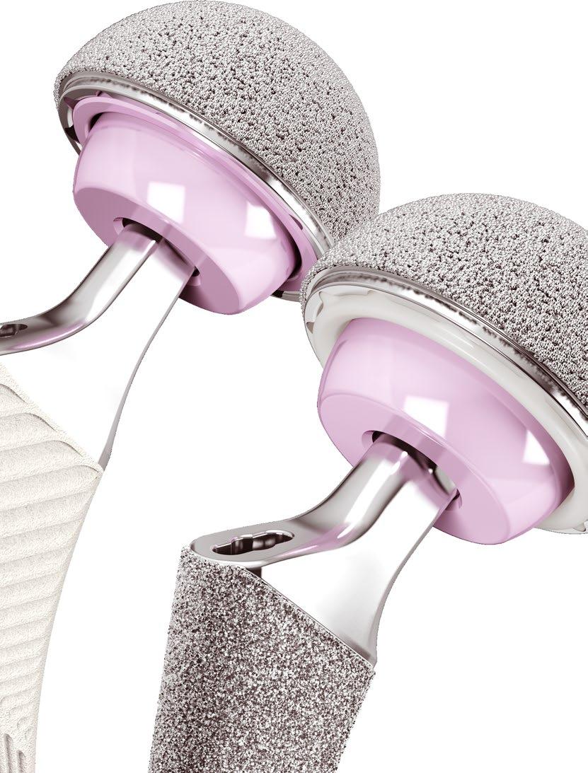
12 IMPLANTING A PINNACLE PRIMARY CUP The natural acetabulum is inclined at an average angle of Therefore when a replacement acetabular component is implanted at the correct position, some cup coating will be visible. To achieve the targeted cup position of inclination and of anteversion, we recommend that 4 6 mm of coating should be left exposed (Figure 11). However, the amount of coating to be left visible is dependant on the angle of the patients acetabulum and the size of the component used Cup Insertion Each PINNACLE Acetabular Cup style is implanted using the same basic surgical technique; however, some cup styles have technique-specific tips that help facilitate implantation. This technique demonstrates the insertion of a PINNACLE 100 Series (no-hole) cup. Before implanting the final prosthesis, take the hip through a full range of motion and stability assessment with all trial components in position. Securely thread the permanent acetabular cup prosthesis onto the acetabular cup positioner (Figure 13). Use the PINNACLE external alignment guide to assist in component orientation. After confirming alignment, impact the prosthesis into position (Figure 12). Given the nature of a hemispherical acetabular component, rim contact will occur before dome seating occurs. This may require additional impaction to ensure seating. Confirm seating by sighting through the apical hole or, if present, screw holes. An apical hole eliminator may be inserted with a standard hex head screwdriver following cup impaction. Following final component seating, if adjustments to the cup orientation are necessary, thread the impactor handle back into the apical hole to adjust the cup position. Avoid adjusting the cup position by impacting the taper region and/or cup face with a punch, as this may cause damage to the taper Figure 11 Securely thread the acetabular cup onto the acetabular cup positioner Figure 12 Confirm acetabular cup alignment Anterior notch Check for psoas tendon impingement with large diameter heads. Posterior Check toe-off impingement. Supero-lateral rim POROCOAT / reamer visible. 10 DePuy Synthes Joint Reconstruction PINNACLE Surgical Technique


 Liner Trial Size (mm) 47, 48 48 49, 50 50 51, 52 52 53, 54 54 55, 56 56 57, 58 58 59, 60 60 61, 62 62 63, 64 64 65, 66 66 67, 68* 68 69, 70* 70 71, 72* 72 40 mm polyethylene trial liners are")
13 POLYETHYLENE TRIAL LINERS Following positioning and seating of the acetabular cup trial, place the appropriate sized liner trial into the trial cup (Figure 13a). Secure the liner trial to the cup trial through the apical hole screw using a standard hex head screwdriver. There are various liner configurations for all head sizes ranging from mm (Figure 13b). With the femoral component trials in position, assess stability and range of motion. Couple the liner trial with the cup trial in the desired position. For liner alternatives other than neutral, there is an orientation reference etch mark on the liner trial and liner implant. Neutral +4 Neutral Lipped Cup and Liner Trial Sizes 28 mm polyethylene trial liners are GREEN 32 mm polyethylene trial liners are BLUE 36 mm polyethylene trial liners are ORANGE Cup Trial Size (mm) Liner Trial Size (mm) 47, , , , , , , , , , , 68* 68 69, 70* 70 71, 72* mm polyethylene trial liners are LIGHT PINK Figure 13b *Appropriate spacer trials to be utilised for head diameters of 28, 32 and 36 mm 44 mm polyethylene trial liners are LIGHT GREEN Figure 13a Trial liners colour guide PINNACLE Surgical Technique DePuy Synthes Joint Reconstruction
14 ALTERNATIVE BEARING TRIAL LINERS When implanting an alternative bearing the trial reduction needs to be done with dedicated trial liners (Figure 14). Please note that alternative bearing trials have a built in offset of +2 mm. Neutral 28 mm alternative bearing trial liners are YELLOW 32 mm alternative bearing trial liners are PINK 36 mm alternative bearing trial liners are PURPLE 40 mm alternative bearing trial liners are AQUA 44 mm alternative bearing trial liners are RED Figure 14 Alternative bearing trial liners colour guide 12 DePuy Synthes Joint Reconstruction PINNACLE Surgical Technique
.")


15 POLYETHYLENE LINER CONFIGURATIONS In the PINNACLE Hip Solutions, a variety of polyethylene liner designs are available. Each design has specific benefits. It is important for the surgeon to understand the geometry of the various liner alternatives and their impact on joint biomechanics and range of motion (Figure 15). 9 Range of Motion information in Figure 15 is shown for movements in Abduction to Adduction, see page 14 Table 1 for more information. Neutral Liner The neutral liner provides 180 of head coverage. The wide face chamfer is optimised for range of motion. The range of motion measured is 119 with a DePuy Synthes AMT 12/14 Taper Stem and a 28 mm +5 head. The femoral head s centre of rotation is concentric with the outer diameter of the cup. +4 Neutral Liner Like the neutral liner, the +4 mm neutral liner provides 180 of head coverage. The wide face chamfer is optimised for range of motion. The range of motion measured is 121 with a DePuy Synthes AMT 12/14 Taper Stem and a 28 mm +5 head. This liner provides a 4 mm lateralisation of the femoral head s centre of rotation. This 4 mm offset both increases soft tissue tensioning and provides 4 mm of increased polyethylene thickness in the cup s dome region. This lateralised liner can be used as an alternative to a longer neck and may enable the surgeon to avoid using a skirted head. A +4 mm lateralised liner will result in about 3 mm of leg length and about 3 mm of offset if the cup is inserted at a 45 abduction angle Face Changing Liner Like the other liners, the liner provides 180 of head coverage and the wide chamfer is optimised for range of motion. The range of motion measured is 115 with a DePuy Synthes AMT 12/14 Taper Stem and a 28 mm +5 head. This liner lateralises the femoral head 4 mm and a 10 face change alters inclination/version dependent upon placement of the liner. Lipped Liner Range of motion is measured at 106 maximum, with a DePuy Synthes AMT 12/14 Taper Stem and a 28 mm +5 head. The lip on this liner can provide additional stability; however, the impact on range of motion and early impingement must be understood. Constrained Liners Constrained liners are available for the PINNACLE cup and are described in brochure Neutral +4 Neutral Face Changing Lipped Figure 15 Liner alternatives 28 mm Inner Diameter (ID) with DePuy Synthes AMT 12/14 Taper Stem (Range of Motion (ROM) calculated as AP sweep angle) 11 PINNACLE Surgical Technique DePuy Synthes Joint Reconstruction

16 POLYETHYLENE LINER CONFIGURATIONS The required ranges of angular movement between the acetabular and femoral components in a total hip joint replacement are specified in ISO 21535:2007(E). 10 The ROM data presented in the below table derive from a computer analysis using 3-dimensional digital models of the actual components. The analysis was carried out on the combinations of PINNACLE and CORAIL hip systems, including cups, liners, femoral heads and femoral components. 9 The acetabular component model was oriented into an initial position which is considered a neutral position for a physiologically oriented acetabular cup component in terms of abduction and version. From the neutral position the femoral stem was rotated until the neck of the stem made contact with the rim of the acetabular cup. The range of motion (ROM) data of physiologically positioned acetabular and femoral components differs from commonly discussed sweep angles and describes maximum achievable movement in flexion and extension, and abduction and adduction (Figure 16). However, these are theoretical numbers and clinical results may be reduced due to skeletal impingement or the presence of soft tissues. Figure 16 The angles achieved in each direction about each axis are shown in the following table: Insert Neutral +4 Neutral Face Lipped Flexion / Extension Abduction / Adduction Flexion / Extension Abduction / Adduction Flexion / Extension Abduction / Adduction Flexion / Extension PE 28 mm PE 32 mm PE 36 mm N/A N/A PE 40 mm * N/A N/A N/A N/A PE 44 mm * N/A N/A N/A N/A PE 48 mm * N/A N/A N/A N/A CERAMIC 28 mm N/A N/A N/A N/A N/A N/A CERAMIC 32 mm N/A N/A N/A N/A N/A N/A CERAMIC 36 mm N/A N/A N/A N/A N/A N/A Abduction / Adduction Table 1 Range of Motion (ROM) tested with a CORAIL 12/14 Taper Stem in accordance with ISO 21535:2009 standard for a physiologically positioned cup and stem. *MARATHON liners in sizes 40, 44 and 48 mm ID are part of the ES3 system and are manufactured with a Charnley bore (raised lip). 14 DePuy Synthes Joint Reconstruction PINNACLE Surgical Technique

. 11 Drill bits of varying lengths are available.")

17 IMPLANTING THE ACETABULAR CUP WITH SCREW FIXATION Screw Insertion The PINNACLE Sector Cup has three screw holes and is designed for insertion with screws. QUICKSET Acetabular Screw Instruments are recommended for screw insertion. Two medial hole alternatives are placed to enable screw placement up the posterior column in either the right or left hip. The single lateral screw provides additional access to the ilium. The drill bit is controlled by the drill guide as it passes through selected holes into the acetabulum (Figure 17). The screw angle may vary by as much as 34 (Figure 18). 11 Drill bits of varying lengths are available. By seating the drill bit completely into the guide, holes corresponding to the effective length of the drill bit will be created. Figure 17 Drill Guide Select holes where the prosthesis is to be anchored with cancellous screws so that the screws lie within a safe quadrant. The safe quadrant is defined by two lines from the anterior inferior iliac spine through the centre of the acetabulum and posterior by a line from the sciatic notch to the centre of the acetabulum (Figure 19) Figure 18 Screw Angulation Figure 19 Screw hole selection PINNACLE Surgical Technique DePuy Synthes Joint Reconstruction
. Insert 6.")
.")
18 IMPLANTING THE ACETABULAR CUP WITH SCREW FIXATION Verify hole depth using the QUICKSET Depth Gauge. Alternating colours on the depth gauge represent 10 mm increments (Figure 20). Insert 6.5 mm PINNACLE Hip Solutions Cancellous Bone Screws using a hex head screwdriver (Figures 21 and 22). The 6.5 mm self tapping screws have four point cutting flutes with a blunt tip to reduce the risk of neurovascular injury (Figure 23). Figure 20 Depth Gauge Figure 21 Screw insertion Figure 22 Screw insertion Figure 23 Screw tip 16 DePuy Synthes Joint Reconstruction PINNACLE Surgical Technique
.")


19 IMPLANTING THE ACETABULAR CUP WITH SPIKES PINNACLE 300 Series Cup Insertion Spikes placed along the radius of the PINNACLE 300 Series cup are coated and are for additional fixation (Figures 24 and 25). The spike height in the 300 Series cup ensures that the spike contacts bone on insertion at the same point that the cup contacts the rim of the prepared acetabulum. This gives the surgeon greater control when inserting the 300 Series cup and ensures the cup bottoms out in the dome of the acetabulum. The recommended acetabular reaming technique for the PINNACLE 300 Acetabular Cup is either 1 mm under or line to line dependent on bone quality. It is important that the cup is well centred in the prepared acetabular cavity in the predetermined alignment indicated by the trial before being impacted. Figure 24 Prior to cup impaction, spikes and rim engage simultaneously when the cup is centred and aligned Spike orientation Spike length Figure 25 PINNACLE Surgical Technique DePuy Synthes Joint Reconstruction
20 POLYETHYLENE LINER INSERTION AND IMPACTION Following insertion of the final acetabular cup and femoral component, the trial liners can be used in the cup to confirm liner selection and evaluate joint stability and range of motion. Prior to inserting the final acetabular liner, thoroughly irrigate and clean the cup. It is important to check the cup/liner locking groove to ensure it is clear of any debris. Remove all soft tissue from the face of the cup so as not to impede liner seating (Figure 26). An apex hole plug may be used prior to liner insertion. Figure 26 Liner placement 18 DePuy Synthes Joint Reconstruction PINNACLE Surgical Technique

.")
21 POLYETHYLENE LINER INSERTION AND IMPACTION Prior to insertion/impaction, mate the liner anti-rotational device (ARD) tabs with the ARD scallops on the cup (Figure 27). There are six ARD tabs on the liners and 12 ARD scallops for cup diameters 48 mm 72 mm. Also, there are four ARD tabs and eight ARD scallops in cup diameters 38 mm 46 mm. This allows the liner to be rotated in 30 increments for cups 48 mm 80 mm and 45 increments for 38 mm 46 mm. Seat the liner using the ID impactor that corresponds to the selected implant. Because the locking mechanism is tapered, it is important to impact the liner directly into the cup with multiple medium blows (Figure 28). Impacting the liner in a tilted position may prevent complete seating. Seating of the liner is visually confirmed when the liner ARDs are flush with the face of the acetabular cup; however, the liner face will remain proud in relation to the cup face by approximately 1 mm for a neutral liner to 4 mm for a lateralised liner (Figure 29). Figure 27 Align the liner anti rotation tabs with cup scallops Figure 28 Liner impaction Figure 29 Seating height of a neutral liner PINNACLE Surgical Technique DePuy Synthes Joint Reconstruction
.")
.")


22 POLYETHYLENE LINER EXTRACTION A polyethylene liner extractor is available to aid in polyethylene liner extraction and to help ensure the PINNACLE Acetabular Cup is not damaged during polyethylene liner extraction (Figure 30). Open the extractor jaws and extend the ARD pin from the extractor tip. Place the ARD pin into an empty ARD and tightly close the jaws of the extractor (Figure 31). The teeth of the extractor should dig into the inner diameter of the polyethylene. Figure 30 Polyethylene Liner Extractor Once the ARD tip and teeth are secure on the polyethylene, advance the extraction knob clockwise until the polyethylene is removed (Figures 32 and 33). It is important to note that an extracted polyethylene liner must not be reused. Figure 31 Extractor placement Figure 32 Rotation of Extraction Knob Figure 33 Polyethylene liner removal 20 DePuy Synthes Joint Reconstruction PINNACLE Surgical Technique


.")
 Gripper (Figure 35) instrumentation is mandatory for the insertion of")
23 ALTERNATIVE BEARING LINER Alternative Bearing Insertion Technique To ensure optimal component placement when using alternative bearing (AB) liners, trialling is critical. Dedicated trials for liners help ensure the correct restoration of biomechanics. If correct joint biomechanics, free of mechanical impingement, cannot be obtained with the alternative bearing trials, perform a trial reduction using the PINNACLE polyethylene liner trials. Then use the PINNACLE polyethylene liner that results in joint stability. 28 mm Alternative Bearing Trial - YELLOW 32 mm Alternative Bearing Trial - PINK 36 mm Alternative Bearing Trial - PURPLE Before placing an alternative bearing into the PINNACLE cup, ensure all mating surfaces are clean and free of debris (Figure 34). Handle the alternative bearing liner carefully to avoid damage that could compromise the mechanical integrity of the liner taper locking mechanism. 40 mm Alternative Bearing Trial - AQUA 44 mm Alternative Bearing Trial - RED Use of the PINNACLE Alternative Bearing (AB) Gripper (Figure 35) instrumentation is mandatory for the insertion of ceramic liners. The surgical technique must be followed when inserting the ceramic liner into the acetabular cup to ensure correct alignment of the liner into the cup prior to impaction. Failure to do so could contribute to rim chipping during insertion or postoperative fracture. Figure 34 Ensure all taper mating surfaces are clean and free of debris Figure 35 Alternative Bearing Gripper PINNACLE Surgical Technique DePuy Synthes Joint Reconstruction
.")
.")
24 ALTERNATIVE BEARING GRIPPER Alternative Bearing Insertion Technique Assemble the appropriate size gripper to the inserter shaft aligning the slot of the gripper with the pin of the shaft (Figure 36). Thread the appropriate size tip to the shaft (Figure 37). Make sure that the gripper is positioned such that it is touching the tip once it has been fully threaded (Figure 38). Figure 36 Figure 37 Figure DePuy Synthes Joint Reconstruction PINNACLE Surgical Technique
.")

25 ALTERNATIVE BEARING GRIPPER Alternative Bearing Insertion Technique Press fit the liner on the gripper component. Verify that the liner is fully seated to ensure proper alignment (Figure 39). Cautiously advance the liner into the incision and align the face of the gripper to the face of the cup. Proper alignment is achieved when the instrument will no longer rotate due to the locking features between the gripper, cup and liner (Figures 40 and 41). Figure 39 Figure 40 Figure 41 PINNACLE Surgical Technique DePuy Synthes Joint Reconstruction
.")

.")
26 ALTERNATIVE BEARING GRIPPER Alternative Bearing Insertion Technique Press firmly on handle to introduce the liner into the cup (Figure 42). Do not attempt to fully engage the taper locking mechanism by striking the end of the AB Gripper Inserter. Carefully remove instrument by pulling back the plastic gripper flange whilst pushing down gently on the gripper handle (Figure 43). Palpate the liner to confirm proper taper alignment and seating in the cup (Figure 44). Figure 42 Figure 43 Figure DePuy Synthes Joint Reconstruction PINNACLE Surgical Technique
. The nature of hard on hard bearings requires precise placement of femoral and acetabular components.")

27 ALTERNATIVE BEARING GRIPPER Alternative Bearing Insertion Technique Use an impactor with appropriate impactor tip for final seating of the liner (Figure 45). Final seating requires two to four moderate blows (Figure 46). The nature of hard on hard bearings requires precise placement of femoral and acetabular components. It is important to optimise component placement to avoid mechanical impingement. To ensure optimal component placement when using alternative bearings, trialling is critical. Dedicated trials for alternative bearings help ensure the correct representation of biomechanics. Note: if any other bearing surface has been impacted into the cup, a CERAMAX liner cannot be used. CERAMAX liners should only be used in new PINNACLE acetabular cups with an "as manufactured" taper. Figure 45 Figure 46 PINNACLE Surgical Technique DePuy Synthes Joint Reconstruction
. Each cup size has a specific extractor, e.g., 48 mm cup uses a 48 mm extractor. Note: AB extractors are available for cups starting at 44 mm OD up to 66 mm OD.")
.")
28 ALTERNATIVE BEARING LINER Alternative Bearing Extraction Technique If it is necessary to remove an AB liner from a PINNACLE cup, thread the extractor handle onto the appropriate size AB extractor (Figure 47). Each cup size has a specific extractor, e.g., 48 mm cup uses a 48 mm extractor. Note: AB extractors are available for cups starting at 44 mm OD up to 66 mm OD. The AB extractor can be used with 28,32,36,40 and 44 mm ID Place the three tips of the AB extractor into any three scallops on the face of the PINNACLE cup (Figure 48). Figure 47 Alternative Bearing Extractor Push down the attached lever with thumb pressure to engage the suction cup against the inner face of the AB liner (Figure 49). To remove the AB liner from the cup, impact the extraction handle lightly one to two times with a metal mallet. The resulting vibration will release the taper lock between the AB liner and the PINNACLE cup. The liner is then lifted out of the cup by the suction cup mechanism (Figure 50). Figure 48 Placement of Alternative Bearing Extractor Figure 49 Engage the suction cup by pushing down on the lever Figure 50 Impact the extractor handle lightly and lift the liner 26 DePuy Synthes Joint Reconstruction PINNACLE Surgical Technique

.")
 until the circumference of the femoral")
 and through a lateral view (Figure 54).")

29 FUNCTIONAL ASSESSMENT Correct component placement is critical for the longevity of the hip reconstruction. Component placement is especially critical when alternative bearings are used in the reconstruction. The following illustration depicts the position of the femoral component neck with relation to the opening of the acetabular component with the reconstructed hip in neutral rotation (Figure 51). To assess the combined anteversion of the femoral stem and acetabular component, place the patient in the lateral decubitus position with the operative hip gently flexed and internally rotated (Figure 52) until the circumference of the femoral head becomes coplanar with the opening of the acetabular insert (i.e., the axis of the femoral neck is perpendicular to the insert face). This position is depicted through a frontal view (Figure 53) and through a lateral view (Figure 54). The angle between horizontal and the internally rotated operative leg provides an estimate of combined anteversion of the acetabular component and the femoral stem. Combined anteversion at degrees is generally acceptable. Figure 51 Figure 52 Combined Anteversion Figure 53 Figure 54 PINNACLE Surgical Technique DePuy Synthes Joint Reconstruction
30 TIGHT EXPOSURE AND STABILITY TIPS Tight Exposure If the exposure is tight, completely incise the anterior capsule, perform a partial or complete release of the gluteus maximus tendon and release the reflected head of the rectus femoris. Stability Assessment Posterior Instability With the trial implants in place, place the hip in 90 degrees of flexion, neutral abduction and internally rotate until subluxation. If there is less than 60 degrees of internal rotation, determine the cause of instability. Prosthetic Impingement Bony Impingement Problem Solution Femoral implant neck levers on the acetabular component rim. Reposition cup to correct version/abduction. Increase head size and evaluate. Increase anteversion of the stem. Problem Solution Prosthetic neck levers on anterior acetabular osteophyte. Greater trochanter impinging on ilium. Remove anterior osteophytes from the acetabulum. Increase stem offset to move the trochanter away from the ilium. Remove anterior trochanteric bone. Soft Tissue Impingement Soft Tissue Laxity Problem Redundant anterior capsule causes head to lever out of socket. Problem Lax soft tissue leading to multidirectional instability. Solution Resect redundant anterior capsule. Solution Increase the neck length. Advance the trochanter. 28 DePuy Synthes Joint Reconstruction PINNACLE Surgical Technique
31 Stability Assessment Anterior Instability With the implant trial in place, place the hip in extension and maximally externally rotate; subluxation should not occur. If subluxation occurs, determine the cause of instability. The Keys to Managing Stability Are: 1. Ensure the appropriate anteversion/abduction of the acetabular and femoral components. 2. Restore correct leg length and femoral offset. 3. Repair the posterior capsule and rotators. Problem Solution Prosthetic Impingement Prosthetic neck impinges on the acetabular cup. Reposition acetabular component to decrease anteversion. Decrease anteversion of the femoral stem. Increase the head size and re-evaluate. 4. Work with the patient to ensure appropriate post-operative precautions are followed. Bony Impingement Problem Solution Femur impinges on the ischium. Increase femoral offset. Decrease acetabular or stem anteversion. PINNACLE Surgical Technique DePuy Synthes Joint Reconstruction

32 CLOSURE Closure is based on the surgeon s preference and the individual case. If the capsule is retained it is closed separately. The gluteus minimus and gluteus medius can be closed separately or as a single unit. At least one stitch is passed through bone. Tension is relieved during the repair with slight internal rotation. The repair should be tested throughout the hip range of motion. 30 DePuy Synthes Joint Reconstruction PINNACLE Surgical Technique
33 ORDERING INFORMATION Instruments PINNACLE Poly Impactor Handle PINNACLE Primary Template PINNACLE Alternative Bearing Suction Cup Inserter PINNACLE Alternative Bearing Extractor Body PINNACLE Alternative Bearing Extractor Body PINNACLE Alternative Bearing Extractor Body PINNACLE Alternative Bearing Extractor Body PINNACLE Alternative Bearing Extractor Body PINNACLE Alternative Bearing Extractor Body PINNACLE Alternative Bearing Extractor Body PINNACLE Alternative Bearing Extractor Body PINNACLE Alternative Bearing Extractor Body PINNACLE Alternative Bearing Extractor Body PINNACLE Alternative Bearing Extractor Body PINNACLE Alternative Bearing Extractor Body PINNACLE Polyethylene Liner Extractor Impactor Tip mm Impactor Tip 26 mm Impactor Tip 28 mm Impactor Tip 32 mm Impactor Tip 36 mm PINNACLE Straight Cup Impactor PINNACLE Version Guide PINNACLE Bantam Acetabular Cup Impacter Adapter PINNACLE Trial Liner Base PINNACLE Trial Liner Lid PINNACLE Alternative Bearing Extractor Case Complete (Case, Tray, Lid) PINNACLE Impactor Tip 40 mm PINNACLE Impactor Tip 44 mm PINNACLE Impactor Tip 48 mm Primary Case Complete (Case, Tray, Lid) PINNACLE AB Inserter Case PINNACLE 28 mm TIP PINNACLE 36 mm TIP AB Curved Handle Assembly PINNACLE 40 mm TIP PINNACLE 44 mm TIP PINNACLE 32 mm TIP PINNACLE 44 mm Gripper PINNACLE 46 mm Gripper PINNACLE 48 mm Gripper PINNACLE 50 mm Gripper PINNACLE 52 mm Gripper PINNACLE 54 mm Gripper PINNACLE 56 mm Gripper PINNACLE 58 mm Gripper PINNACLE 60 mm Gripper PINNACLE 62 mm Gripper PINNACLE 64 mm Gripper PINNACLE 66 mm Gripper Acetabular Alignment Guide Poly Extractor Screwdriver QUICKSET Ratchet Screwdriver Handle QUICKSET Tapered Rigid Hex Screwdriver QUICKSET Tapered Flexible Hex Screwdriver QUICKSET Tapered Hex Screwdriver Cardan QUICKSET Cross Head Screwdriver QUICKSET Flexible Quick Couple Drill Shaft QUICKSET Rigid Quick Couple Drill Shaft QUICKSET Drill Guide 3.8 mm QUICKSET Screw Holding Forceps QUICKSET Ø 3.8 mm Drill Bit 25 mm QUICKSET Ø 3.8 mm Drill Bit 55 mm QUICKSET Ø 3.8 mm Drill Bit 70 mm QUICKSET 70 mm Depth Gauge QUICKSET Tapered Hex Screwdriver U-Joint Apex Hole Elim Tapered Hex Driver Replacement Suction Cup For more detailed information on PINNACLE implants and related trial instruments please refer to the PINNACLE Primary System Overview PINNACLE Surgical Technique DePuy Synthes Joint Reconstruction
34
35
36 References 1. Learmonth ID, Young C, Rorabeck C. The operation of the century: total hip replacement. Lancet 2007;370: Archbold HAP et al. The transverse acetabular ligament: an aid to orientation of the acetabular component during primary total hip replacement. J Bone Joint Surg. 2006;88B: Udomkiat P, Dorr LD, Wan Z. Cementless hemispheric porous-coated sockets implanted with press-fit technique without screws: average ten-year follow-up. J Bone Joint Surg. 2002;84A: Schmalzried TP, Guttmann D, Grecula M, Amstutz H. The relationship between the design, position, and articular wear of acetabular components inserted without cement and the development of pelvic osteolysis. J Bone Joint Surg. 1994;76A: Kennedy JG, Rogers WB, Soffee KE, et al. Effect of acetabular component orientation on recurrent dislocation, pelvic osteolysis, polyethylene wear and component migration. J Arthroplasty 1998;13: Prudhommeaux F, Hamadouche M, Nevelos J, et al. Wear of alumina-on-alumina total hip arthroplasties at a mean 11-year followup. Clin Orthop Relat Res. 2000; 397: Walter WL, O Toole GC, Walter WK, Ellis A, Zicat BA. Squeaking in ceramic-on ceramic hips: the importance of acetabular component orientation. J Arthroplasty. 2007;22: Tower SS, Currier JH, Currier BH, Lyford KA, Van Citters DW, Mayor MB. Rim cracking of the cross-linked longevity polyethylene acetabular liner after total hip arthroplasty. J Bone Joint Surg. 2007;89A(10): Data on file DVE ROM December International Standards Organisation, ISO 21535:2009 Non-active surgical implants. Joint replacement implants. Specific requirements for hip-joint replacement implants. Available from URL: [Accessed 17/12/12]. 11. Data on File. DePuy Synthes Internal Test report L /2013. Johnson & Johnson Medical Limited PO BOX 1988, Simpson Parkway, Livingston, West Lothian, EH54 0AB, United Kingdom. Incorporated and registered in Scotland under company number SC DePuy Orthopaedics, Inc. 700 Orthopaedic Drive Warsaw, IN USA Tel: +1 (800) Fax: +1 (574) DePuy International Ltd St Anthony s Road Leeds LS11 8DT England Tel: +44 (0) Fax: +44 (0) DePuy (Ireland) Loughbeg Ringaskiddy Co. Cork Ireland Tel: Fax: depuysynthes.com Johnson & Johnson Medical Limited All rights reserved. CA#DPEM/ORT/1112/0366(2) Issued:10/14
This publication is not intended for distribution in the USA. SURGICAL TECHNIQUE
 This publication is not intended for distribution in the USA. SURGICAL TECHNIQUE DePuy Synthes DURALOC Surgical Technique CONTENTS Templating and Pre Operative Planning 2 Preparation of the Acetabulum
Templating and Pre Operative Planning 2. Preparation of the Acetabulum 4. Trial Sizing and Impaction of the Shell 5.
 Surgical Technique Contents Templating and Pre Operative Planning 2 Preparation of the Acetabulum 4 Trial Sizing and Impaction of the Shell 5 Cup Positioning 6 Joint Stability 7 Trial sizing and Impaction
PINNACLE Hip Solutions. Surgical Techniques
 PINNACLE Hip Solutions Surgical Techniques 2 DePuy Synthes PINNACLE Hip Solutions Surgical Technique Contents Introduction 3 Surgical Technique Templating and Pre Operative Planning 4 Acetabular Reaming
DePuy Orthopaedics, Inc. 700 Orthopaedic Drive Warsaw, IN USA Tel: +1 (800) Fax: +1 (574)
 Fax: +1 (574)") References 1. Sanchez-Sotelo J, Haidukewych GJ, Boberg CJ. Hospital Cost of Dislocation After Primary Total Hip Arthroplasty. J Bone Joint Surg. 2006;88A:290-294. 2. Brodner W, Grübl A, Jankovsky R, Meisinger
References 1. Sanchez-Sotelo J, Haidukewych GJ, Boberg CJ. Hospital Cost of Dislocation After Primary Total Hip Arthroplasty. J Bone Joint Surg. 2006;88A:290-294. 2. Brodner W, Grübl A, Jankovsky R, Meisinger
DURALOC. Acetabular Cup System. Surgical Technique
 DURALOC Acetabular Cup System Surgical Technique Table of Contents Surgical Technique Templating and Pre Operative Planning 2 Preparation of the Acetabulum 4 Trial Sizing and Impaction of the Shell 5
PRODUCT RATIONALE & SURGICAL TECHNIQUE
 This publication is not intended for distribution in the USA. PRODUCT RATIONALE & SURGICAL TECHNIQUE THE PRODUCT OF LONG-TERM CLINICAL EXPERIENCE The TRILOC cemented UHMWPE cup is a direct descendant of
SURGICAL TECHNIQUE IMPROVED WEAR REDUCTION PROVEN FIXATION PRECISE INSTRUMENTATION RELIABILITY
 SURGICAL TECHNIQUE IMPROVED WEAR REDUCTION PROVEN FIXATION PRECISE INSTRUMENTATION RELIABILITY TABLE OF CONTENTS Surgical Technique PAGE 02 PAGE 04 PAGE 06 PAGE 09 PAGE 10 PAGE 14 PAGE 15 PAGE 16 PAGE
Approach Patients with Confidence
 Approach Patients with Confidence The is the first stem specifically designed to be utilized with tissue sparing approaches, such as the anterior approach, as well as traditional approaches. The implant
This publication is not intended for distribution in the USA. SURGICAL TECHNIQUE
 This publication is not intended for distribution in the USA. SURGICAL TECHNIQUE CONTENTS Introduction 2 Pre-operative Planning 4 Determining the Centre of Rotation 5 Surgical Technique 6 Acetabular Preparation
Surgical Technique CERAMAX ULTAMET MARATHON FREEDOM TO CHOOSE WITHOUT COMPROMISE
 Surgical Technique CERAMAX ULTAMET MARATHON FREEDOM TO CHOOSE WITHOUT COMPROMISE Contents Introduction 3 Surgical Philosophy 4 Surgical Technique Templating and Pre-operative Planning 6 Surgical Approach
Operative Technique Crown Cup Acetabular System
 EXACTECH HIP Operative Technique Crown Cup Acetabular System TABLE OF CONTENTS PRE-OPERATIVE PLANNING... 1 TEMPLATING... 1 INDICATIONS FOR USE... 1 CONTRAINDICATIONS FOR USE... 1 OPERATIVE TECHNIQUE OVERVIEW...
Minimally Invasive System for Total Hip Arthroplasty. Surgical Technique
 Minimally Invasive System for Total Hip Arthroplasty Surgical Technique INTRODUCTION The DePuy MI System was created by an International team of surgeons whose first priority was to achieve patient gain
Manza Cup HA SURGICAL TECHNIQUE.
 1 PRE-OPERATIVE PLANNING. Preoperative assessment of the appropriate size and position of the acetabular component will provide intraoperative guidance for acetabular reaming. To determine the acetabluar
CERAMAX CERAMiC ToTAl Hip SySTEM SuRgiCAl TECHniquE
 CERAMAX Ceramic Total Hip System Surgical Technique Table of Contents Surgical Technique introduction 5 Templating and Pre-operative Planning 6 Surgical Approach Anterolateral 8 Surgical Approach Posterolateral
CERAMAX Ceramic Total Hip System. Surgical Technique
 CERAMAX Ceramic Total Hip System Surgical Technique Table of Contents Surgical Technique Introduction 5 Templating and Pre-operative Planning 6 Surgical Approach Anterolateral 8 Surgical Approach Posterolateral
Dual Mobility System Evaluation surgical technique
 Trinity Dual Mobility System Evaluation surgical technique Contents Operative summary 4 Overview 5 Operative technique 6 1. Acetabular reaming 6 Reamer guide 6 2. Acetabular shell trial 6 3. Acetabular
Dual Mobility System Surgical technique
 Trinity Dual Mobility System Surgical technique 2 Contents Operative summary 4 Overview 5 Operative technique 6 1. Acetabular reaming 6 Reamer guide 6 2. Acetabular shell trial 7 3. Acetabular shell implantation
Trinity. Advanced Bearing Acetabular System Surgical technique
 Advanced Bearing Acetabular System Surgical technique Contents Operative summary Introduction Pre-operative planning Acetabular preparation Acetabular reaming Reamer guide Acetabular shell trials Acetabular
AUTOBLOQUANTE AUTOBLOQUANTE. Product Rationale Surgical Technique
 AUTOBLOQUANTE AUTOBLOQUANTE Product Rationale Surgical Technique AUTOBLOQUANTE The Product of Long-Term Clinical Experience The AUTOBLOQUANTE femoral component is a direct descendant of the original straight
OPTIONAL/ADDITIONAL INSTRUMENTS
 20 Elevated 6320-36-22 20 Elevated Rim Liner, 36mm OD x 22mm ID 6320-80-22 20 Elevated Rim Liner, 80mm OD x 22mm ID 6320-42-26 20 Elevated Rim Liner, 42mm OD x 26mm ID 6320-80-26 20 Elevated Rim Liner,
Enhanced Stability Constrained Liners. Design Rationale Surgical Technique
 Enhanced Stability Constrained Liners Design Rationale Surgical Technique The Pinnacle Acetabular Cup System was designed to maximize the number of options available to the surgeon, and provide those options
Bone Preservation Stem
 TRI-LOCK Bone Preservation Stem Featuring GRIPTION Coating Surgical Technique Implant Geometry Extending the TRI-LOCK Stem heritage The original TRI-LOCK Stem was introduced in 1981. This implant was
*smith&nephew CONTOUR
 Surgical Technique *smith&nephew CONTOUR Acetabular Rings CONTOUR Acetabular Rings Surgical technique completed in conjunction with Joseph Schatzker MD, BSc (Med.), FRCS (C) Allan E. Gross, MD, FRCS (C)
Approach Patients with Confidence
 Surgical Technique Approach Patients with Confidence The ACTIS Total Hip System is the first DePuy Synthes stem specifically designed to be utilized with tissue sparing approaches, such as the anterior
SURGICAL TECHNIQUE FIXATION FIRST ADVANCED MODULARITY MANAGING DISLOCATION WEAR REDUCTION VIP TAPER OPTIMIZING RANGE OF MOTION AND STABILITY
 SURGICAL TECHNIQUE FIXATION FIRST ADVANCED MODULARITY VIP TAPER MANAGING DISLOCATION OPTIMIZING RANGE OF MOTION AND STABILITY WEAR REDUCTION TABLE OF CONTENTS PAGE 02 Design Mission and Vision PAGE 03
Surgical Technique. Cup System
 Surgical Technique Cup System INDICATIONS AND USAGE Indications for the use of the CS2 ACETABULAR CUP SYSTEM must be carefully considered with respect to the patient s entire evaluation and alternative
Encina Taper Stem. Stinson Orthopedics Inc. 303 Twin Dolphin Drive, Suite 600 Redwood City, CA
 Stinson Orthopedics Inc. 303 Twin Dolphin Drive, Suite 600 Redwood City, CA 94065 info@stinsonortho.com www.stinsonortho.com Table of Contents Introduction 3 Features 4 Surgical Technique 5 Preoperative
Trilogy Acetabular System
 Trilogy Acetabular System Surgical Technique Versatility in a proven design Trilogy Acetabular System 1 Trilogy Acetabular System Surgical Technique Table of Contents Acetabular Reaming 2 Component Sizing
Optimum implant geometry
 Surgical Technique Optimum implant geometry Extending proven Tri-Lock heritage The original Tri-Lock was introduced in 1981. This implant was the first proximally coated tapered-wedge hip stem available
PINNACLE REVISION CUP SYSTEM
 PINNACLE REVISION CUP SYSTEM This publication is not intended for distribution in the USA. DESIGN RATIONALE FLEXIBILITY. PRECISION. CONFIDENCE. DePuy Synthes Joint Reconstruction is proud to offer the
Trilogy Acetabular System
 Trilogy Acetabular System Surgical Technique Versatility in a proven design Trilogy Acetabular System 1 Trilogy Acetabular System Surgical Technique Table of Contents Acetabular Reaming 2 Component Sizing
ACETABULAR CUP SURGICAL TECHNIQUE
 ACETABULAR CUP SURGICAL TECHNIQUE ACETABULAR CUP DEVICE INDICATIONS FOR USE The ICONACY I-Hip total hip replacement is indicated for the following conditions: 1. A severely painful and/or disabled hip
AML Hip System. Design Rationale/ Surgical Technique
 AML Hip System Design Rationale/ Surgical Technique Design Rationale Evolution In 1977, DePuy Synthes Companies introduced the original cementless total hip. The AML Hip launched in order to solve one
RECLAIM REVISION SOLUTIONS
 RECLAIM REVISION SOLUTIONS Where Strength and Modularity Connect This publication is not intended for distribution in the USA. SURGICAL TECHNIQUE CONTENTS RECLAIM Modular Revision Hip System SURGICAL TECHNIQUE
HIP SYSTEM SURGICAL TECHNIQUE
 HIP SYSTEM SURGICAL TECHNIQUE Introduction...2 Preoperative Planning...3 Preoperative Planning...3 Templating and Radiographs...4 Determination of Leg Length Discrepancy...5 Determining Acetabular Cup
ESC. Enhanced Stability Liners. Design Rationale & Surgical Technique
 ESC Enhanced Stability Liners Design Rationale & Surgical Technique Choice Without Compromise DePuy Synthes PINNACLE Hip Solutions are designed with a wide range of acetabular cup options, biological and
FMP Surgical Technique
 Contents Design Rationale....3 Indications.... 4 Contraindications.... 4 Preoperative Planning.... 4 Surgical Snapshot.... 5 Surgical Technique.... 6 Sizing Chart.... 11 Instrument Guide.... 12 Individual
Rx90 Total Hip System Acetabular Series
 Rx90 Total Hip System Acetabular Series The Rx90 Total Hip System was developed by Stanley Asnis, M.D., in conjunction with David Dines, M.D. and Micheal Errico M.D., Co-Section-Chiefs of the North Shore
pact SYSTEM Surgical Technique HEMISPHERICAL CEMENTLESS CUP SYSTEM MULTI-HOLE & RIM-HOLE Hip Knee Spine Navigation
 pact SYSTEM HEMISPHERICAL CEMENTLESS CUP SYSTEM MULTI-HOLE & RIM-HOLE Surgical Technique Hip Knee Spine Navigation Mpact Surgical Technique Hip Knee Spine Navigation PREFACE The Mpact Multi-hole and the
FLH183 04/08. Biomet UK Ltd Waterton Industrial Estate Bridgend, South Wales CF31 3XA, United Kingdom. Tel. +44 (0) Fax: +44 (0)
 Fax: +44 (0)") FLH183 04/08 Biomet UK Ltd Waterton Industrial Estate Bridgend, South Wales CF31 3XA, United Kingdom Tel. +44 (0)1656 655221 Fax: +44 (0)1656 645454 Exceed ABT Operative Technique The Exceed ABT TM acetabular
FLH183 04/08 Biomet UK Ltd Waterton Industrial Estate Bridgend, South Wales CF31 3XA, United Kingdom Tel. +44 (0)1656 655221 Fax: +44 (0)1656 645454 Exceed ABT Operative Technique The Exceed ABT TM acetabular
Clinical Evaluation Surgical Technique
 Clinical Evaluation Surgical Technique Table of Contents EMPERION Specifications 3 EMPERION Surgical Technique 9 EMPERION Catalog 18 Nota Bene: This technique description herein is made available to the
Preoperative Planning. The primary objectives of preoperative planning are to:
 Preoperative Planning The primary objectives of preoperative planning are to: - Determine preoperative leg length discrepancy. - Assess acetabular component size and placement. - Determine femoral component
Integral 180 Surgical Technique
 Integral 180 Surgical Technique The Integral 180 and 225 are part of the Alliance Family Total Hip System. The Integral 225 femoral component is marketed for use with bone cement in the United States.
Longevity Offset and Oblique Liners. Surgical Technique
 Longevity Offset and Oblique Liners Surgical Technique Longevity Offset & Oblique Liners Surgical Technique 1 Introduction Complete Acetabular System Joint instability is an important issue in both primary
CC TRIO VERSAFITCUP. Surgical Technique. each to their own. Hip Knee Spine Navigation
 VERSAFITCUP CC TRIO each to their own Surgical Technique Hip Knee Spine Navigation Versafitcup CC TRIO Surgical Technique Hip Knee Spine Navigation EACH TO THEIR OWN The Versafitcup CC Trio is a range
Bi-Polar 22.2mm & 28mm System - Operative technique
 Disclaimer Biomet UK Ltd, as the manufacturer of this device, does not practice medicine and does not recommend any particular surgical technique for use on a specific patient. The surgeon who performs
Surgical Technique. CONQUEST FN Femoral Neck Fracture System
 Surgical Technique CONQUEST FN Femoral Neck Fracture System Table of Contents Introduction... 3 Indications... 3 Product Overview... 4 Surgical Technique... 5 Patient Positioning... 5 Reduce the Fracture...
S U R G I C A L T E C H N I Q U E
 SURGICAL TECHNIQUE RECOVERY FUNCTION SURVIVORSHIP DePuy believes in an approach to total hip replacement that places equal importance on recovery, function and survivorship. The DePuy PROXIMA Hip System
Trilogy Acetabular System
 Trilogy Acetabular System Surgical Technique Versatility in a proven design Trilogy Acetabular System 1 Trilogy Acetabular System Surgical Technique Table of Contents Acetabular Reaming 2 Component Sizing
Surgical Technique r5.indd 1 12/8/10 10:36 AM
 Surgical Technique The science of simplicity With more than 700,000 implantations and two and a half decades of clinical success, the Corail Total Hip System now has the most extensive experience with
Stinson Orthopedics Inc. 303 Twin Dolphin Drive, Suite 600 Redwood City, CA
 Stinson Orthopedics Inc. 303 Twin Dolphin Drive, Suite 600 Redwood City, CA 94065 info@stinsonortho.com www.stinsonortho.com Encina HA Stem Table of Contents Introduction 3 Encina HA Stem Features 4 Surgical
CAUTION: Ceramic liners are not approved for use in the United States.
 Total Hip Prostheses, Self-Centering Hip Prostheses and Hemi-Hip Prostheses IMPORTANT: This essential product information sheet does not include all of the information necessary for selection and use of
SURGICAL TECHNIQUE CEMENTED & PRESS-FIT UNIFIED INSTRUMENTATION INTRAOPERATIVE FLEXIBILITY PROVEN BIOMECHANICS
 SURGICAL TECHNIQUE CEMENTED & PRESS-FIT UNIFIED INSTRUMENTATION INTRAOPERATIVE FLEXIBILITY PROVEN BIOMECHANICS INTRODUCTION The Summit Tapered Hip System s comprehensive set of implants and instruments
Distal Cut First Femoral Preparation
 Surgical Technique Distal Cut First Femoral Preparation Primary Total Knee Arthroplasty LEGION Total Knee System Femoral preparation Contents Introduction...3 DCF femoral highlights...4 Preoperative planning...6
Cementless Tapered Femoral Stem Surgical technique
 Cementless Tapered Femoral Stem Surgical technique Contents Operative summary 4 Pre-operative planning 5 Femoral neck osteotomy 5 Femoral canal preparation 5 Intra-medullary (IM) reamer 6 Sequential rasping
TaperFill. Surgical Technique
 TaperFill Surgical Technique Table of Contents Indications and Contraindications 3 TaperFill Hip Size Charts 4-5 DJO Surgical 9800 Metric Boulevard Austin, TX (800) 456-8696 www.djosurgical.com Preoperative
Fixed and Variable Geometry Total Shoulder Arthroplasty
 Fixed and Variable Geometry Total Shoulder Arthroplasty RECOVERY FUNCTION SURVIVORSHIP DePuy believes in an approach to total shoulder replacement that places equal importance on recovery, function and
Cementless Tapered Femoral Stem Surgical technique
 Cementless Tapered Femoral Stem Surgical technique Contents Operative summary 4 Pre-operative planning 5 Femoral neck osteotomy 5 Femoral canal preparation 5 Intra-medullary (IM) reamer 6 Sequential rasping
TRK REVISION KNEE Surgical Technique
 1 TRK REVISION KNEE Surgical Technique 1. 2. 3. 4. 5. 6. 7. 8. 9. 10. INTERCONDYLAR RESECTION...... page FEMORAL STEM...... page NON CEMENTED FEMORAL STEM...... page TRIAL FEMORAL COMPONENTS...... page
TOTAL KNEE ARTHROPLASTY SYSTEM
 SURGICAL TECHNIQUE TOTAL KNEE ARTHROPLASTY SYSTEM 90-SRK-700000 B.0 0 Contents 1. Implant Sizing 2. Surgical Technique a. Incision and Exposure b. Distal Femoral Resection c. Tibial Resection d. Femoral
THE NATURAL FIT. Surgical Technique. Hip Knee Spine Navigation
 THE NATURAL FIT Surgical Technique Hip Knee Spine Navigation MiniMAX Surgical Technique Hip Knee Spine Navigation INTRODUCTION The MiniMAX TM is a cementless anatomic stem available in 9 right sizes and
VerSys LD/Fx Cemented and Press-Fit Hip Prostheses. Surgical Technique IMAGE TO COME. Versatile solutions for total and partial hip replacement
 VerSys LD/Fx Cemented and Press-Fit Hip Prostheses Surgical Technique IMAGE TO COME Versatile solutions for total and partial hip replacement VerSys LD/Fx Cemented and Press-Fit Hip Prostheses VerSys
CORAIL HIP SYSTEM SURGICAL TECHNIQUE
 CORAIL HIP SYSTEM SURGICAL TECHNIQUE THE SCIENCE OF SIMPLICITY With 2,000,000 stems provided for patients worldwide 1 and thirty years of clinical history, the CORAIL Total Hip System now has a very extensive
Zimmer NexGen MIS Tibial Component. Cemented Surgical Technique IMAGE TO COME
 Zimmer NexGen MIS Tibial Component Cemented Surgical Technique IMAGE TO COME Zimmer NexGen MIS Tibial Component Cemented Surgical Technique 1 Zimmer NexGen MIS Tibial Component Cemented Surgical Technique
Optimum implant geometry
 Design Rationale Optimum implant geometry Extending proven Tri-Lock heritage The original Tri-Lock was introduced in 1981. This implant was the first proximally coated tapered-wedge hip stem available
LAMINA SPREADER SURGICAL TECHNIQUE
 LAMINA SPREADER SURGICAL TECHNIQUE Balanced and appropriate external rotation of the femoral component is important for tibio-femoral stability in flexion and patello-femoral tracking/function. Depending
Optimizing function Maximizing survivorship Accelerating recovery
 Surgical Technique Optimizing Function Maximizing Survivorship Accelerating Recovery The company believes in an approach to patient treatment that places equal importance on: Optimizing function Maximizing
ADDRESSING CLINICAL ISSUES OF CEMENTLESS HIP ARTHROPLASTY
 E C H E L O N P R I M A R Y H I P S Y S T E M P R O D U C T R A T I O N A L E ADDRESSING CLINICAL ISSUES OF CEMENTLESS HIP ARTHROPLASTY Echelon Primary Total Hip System HIGH OFFSET STANDARD OFFSET Cementless
Extramedullary Tibial Preparation
 Surgical Technique Extramedullary Tibial Preparation Primary Total Knee Arthroplasty LEGION Total Knee System Extramedullary tibial preparation Contents Introduction...2 EM tibial highlights...3 Preoperative
Scan Bi-Polar 22/28. Operative Technique
 Scan Bi-Polar 22/28 Operative Technique Disclaimer This publication and all content, artwork, photographs, names, logos and marks contained in it are protected by copyright, trademarks and other intellectual
U2 PSA. Revision Knee. Surgical Protocol
 U2 PSA TM Revision Knee Surgical Protocol Table of Contents 1 Component Removal... 1 2 Tibial Preparation... 1 2.1 Tibial Canal Preparation... 1 2.2 Proximal Tibial Resection... 2 2.3 Non Offset Tibial
EVOLVING OUR HERITAGE, MEETING YOUR NEEDS. Surgical Technique
 EVOLVING OUR HERITAGE, MEETING YOUR NEEDS Surgical Technique Joint Spine Sports Med Mpact DM Surgical Technique Joint Spine Sports Med INTRODUCTION The Mpact DM is part of the Mpact Acetabular System and
28 Surgical Technique
 Surgical Technique 10 12 14 16 18 20 22 24 28 26 Technique described by James L. Guyton, MD Campbell Clinic Memphis, Tennessee James W. Harkess, MD Campbell Clinic Memphis, Tennessee David G. LaVelle,
ZMR Over-the-Junction Instruments for Revision Hip Arthroplasty. Surgical Technique IMAGE TO COME
 ZMR Over-the-Junction Instruments for Revision Hip Arthroplasty Surgical Technique IMAGE TO COME ZMR Over-the-Junction Instruments for Revision Hip Arthroplasty Introduction The ZMR Over-the-Junction (OTJ)
CHARNLEY Wires. Surgical Techniques
 CHARNLEY Wires Surgical Techniques BACKGROUND CHARNLEY Trochanteric Wires are indicated for use in re-attachment of the greater trochanter following a trochanteric osteotomy. The use of a double wire
PAL Pelvic Alignment Level
 PAL Pelvic Alignment Level Surgical Protocol For consistency during surgery Pelvic Alignment Level (PAL) Features Pelvic Alignment Level Surgical Protocol To Table To Floor 1. Patient Positioning & Preparation
StelKast Acetabular. Surgical Protocol and Product Specifications. Including ProForm, Provident, Provident Apical Threaded Hole & Systems
 StelKast Acetabular Surgical Protocol and Product Specifications Including ProForm, Provident, Provident Apical Threaded Hole & Systems StelKast Acetabular Surgical Protocol Introduction StelKast offers
Zimmer M/L Taper Hip Prosthesis. Surgical Technique
 Zimmer M/L Taper Hip Prosthesis Surgical Technique Zimmer M/L Taper Hip Prosthesis 1 Zimmer M/L Taper Hip Prosthesis Surgical Technique Table of Contents Preoperative Planning 2 Determination of Leg Length
THE P.F.C. SIGMA FEMORAL ADAPTER. Surgical Technique
 THE P.F.C. SIGMA FEMORAL ADAPTER Surgical Technique Contents P.F.C. Sigma Femoral Adapter and Revision Knee Surgery Introduction 2 Preoperative Planning 2 Overview 3 Surgical Technique Preparation of the
Metasul LDH Large Diameter Head
 Metasul LDH Large Diameter Head Surgical Technique Metasul LDH Large Diameter Head Surgical Technique Enhancing Stability and Increasing Range of Motion Metasul LDH Large Diameter Head Surgical Technique
Patella Planing System
 REFERENCE GUIDE AND SURGICAL TECHNIQUE Patella Planing System SPECIALIST INSTRUMENTS AN ONLAY PATELLA PREPARATION SYSTEM TECHNIQUE FOR PRIMARY PATELLAR RESURFACING The Specialist 2 Patellar Planer System
PROCOTYL E Acetabular Cup System. Modular to Fit Patient s Anatomy. Versatile for Revisions.
 PROCOTYL E Acetabular Cup System Modular to Fit Patient s Anatomy. Versatile for Revisions. TM PROCOTYL E Shell is a revision modular shell manufactured from titanium alloy. It is ovoid-shaped, with a
NEUFLEX MCP/PIP FINGER JOINT IMPLANT SYSTEMS SURGICAL TECHNIQUE. This publication is not intended for distribution in the USA.
 NEUFLEX MCP/PIP FINGER JOINT IMPLANT SYSTEMS This publication is not intended for distribution in the USA. SURGICAL TECHNIQUE MCP SURGICAL TECHNIQUE Summary provided by designing surgeon Arnold-Peter C.
MIS Cemented Tibial Component
 MIS Cemented Tibial Component NexGen Complete Knee Solution Surgical Technique Table of Contents Surgical Exposure... 2 Finish the Tibia... 2 Position Based on Anatomic Landmarks... 3 Lateral Posterior
Arcos Interlocking Distal Stem. Surgical Technique Addendum to the Arcos Modular Femoral Revision System
 Arcos Interlocking Distal Stem Surgical Technique Addendum to the Arcos Modular Femoral Revision System One Surgeon. One Patient. Over 1 million times per year, Biomet helps one surgeon provide personalized
PLR. Proximal Loading Revision Hip System
 PLR Proximal Loading Revision Hip System The PLR splined revision stem is designed to recreate the natural stresses in the revised femur, where proximal bone may be compromised. PLR Hip System Design Considerations
Design Rationale. ECHELON Primary Hip System
 Design Rationale ECHELON Primary Hip System ECHELON Primary Total Hip System Addressing clinical issues of cementless hip arthroplasty Cementless total hip arthroplasty has provided a proven method of
Hip Resurfacing System
 Hip Resurfacing System The Arthrosurface HemiCAP Hip Hemiarthroplasty System restores the articular surface geometry of the femoral head and preserves functional structures using an innovative 3 dimensional
operative technique Kent Hip
 operative technique Kent Hip The Kent Hip Operative Technique The Kent Hip was developed by Mr Cliff Stossel, FRCS in Maidstone, Kent, UK and first implanted in 1986. It was designed to deal with problems
Signature Personalized Patient Care
 Surgical Technique Acetabular Guide System Contents One Surgeon. One Patient. Over 1 million times per year, Biomet helps one surgeon provide personalized care to one patient. The science and art of medical
RECOVERY. P r o t r u s i o
 RECOVERY P r o t r u s i o TM C a g e RECOVERY P r o t r u s i o TM C a g e Design Features Revision acetabular surgery is a major challenge facing today s total joint revision surgeon. Failed endo/bi-polars,
Zimmer NexGen Trabecular Metal Tibial Tray
 Zimmer NexGen Trabecular Metal Tibial Tray Surgical Technique Zimmer NexGen Trabecular Metal Tibial Tray Surgical Technique Give Bone A Solid Hold Zimmer NexGen Trabecular Metal Tibial Tray Surgical Technique
Allofit /Allofit -S IT Alloclassic Acetabular Cup System
 Allofit /Allofit -S IT Alloclassic Acetabular Cup System Surgical Technique Primary Stability and Simple Application 06.01651.012_2010-01_ST_Allofit.indd 1 16.09.2010 10:07:27 Uhr 06.01651.012_2010-01_ST_Allofit.indd
Triple Tapered Stabilised Hip C-STEM AMT. Surgical Technique
 Triple Tapered Stabilised Hip C-STEM AMT Surgical Technique CONTENTS Pre-operative planning: X-ray templating 2 Step 1: Femoral Neck Resection 3 Step 2: Opening the Femoral Canal 4 Step 3: Metaphyseal
Intramedullary Tibial Preparation
 Surgical Technique Intramedullary Tibial Preparation Primary Total Knee Arthroplasty LEGION Total Knee System Intramedullary tibial preparation Contents Introduction...2 IM tibial highlights...3 Preoperative
Featuring. Technology. Product Rationale
 Featuring Technology Product Rationale 2 Optimum implant geometry Extending proven TRI-LOCK heritage The original TRI-LOCK Stem was introduced in 1981. This implant was the first proximally coated tapered-wedge
FLH /11
 FLH 225 04/11 This publication has been issued by: European Central Marketing Waterton Industrial Estate Bridgend, South Wales CF31 3XA, United Kingdom Tel: +44 (0)1656 655221 Fax: +44 (0)1656 645454 www.biomet.com
Restoration Anatomic Acetabular System Surgical Technique
 Restoration Anatomic Acetabular System Surgical Technique Table of Contents Introduction... 1 Step 1 Pre-operative Planning and X-Ray Evaluation... 2 Step 2 Acetabular Preparation... 3 Step 3 Spherical
VerSys Fiber Metal Taper Hip Prosthesis. Surgical Technique
 VerSys Fiber Metal Taper Hip Prosthesis Surgical Technique VerSys Fiber Metal Taper Hip Prosthesis Surgical Technique 1 VerSys Fiber Metal Taper Hip Prosthesis Surgical Technique Table of Contents Preoperative