FMP Surgical Technique
|
|
|
- Elizabeth Osborne
- 5 years ago
- Views:
Transcription
1

2 Contents Design Rationale....3 Indications Contraindications Preoperative Planning Surgical Snapshot Surgical Technique Sizing Chart Instrument Guide Individual results may vary. DJO Surgical is a manufacturer of orthopedic implants and does not practice medicine. This surgical technique was prepared in conjunction with licensed health care professionals. The treating surgeon is responsible for determining the appropriate treatment, technique(s), and product(s) for each individual patient. 2


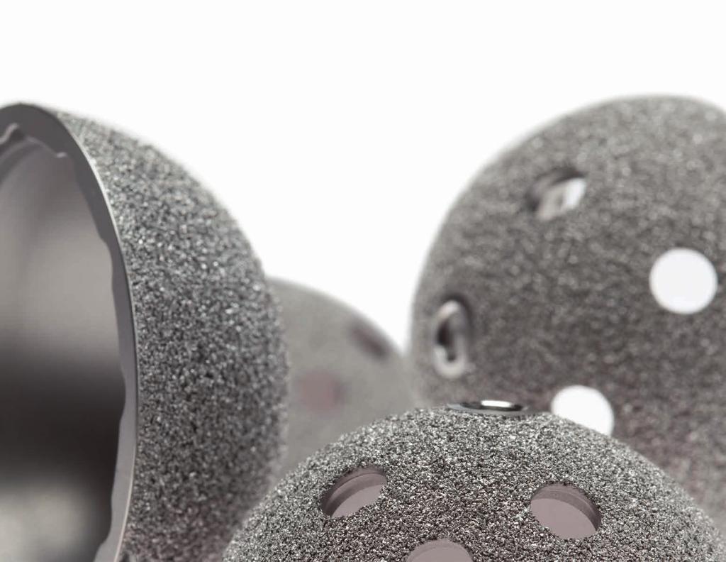
3 System Features THE FMP ACETABULAR SYSTEM CONSISTS OF THE FOLLOWING: Porous hemispherical acetabular shell with clustered screw holes Porous hemispherical acetabular shell without screw holes Porous hemispherical acetabular shell with three spikes Porous hemispherical acetabular shell with multiple screw holes Porous flared rim acetabular shell with clustered screw holes Porous flared rim acetabular shell without screw holes Various compression molded, X-alt, and HXe+ highly Cross-Linked polyethylene liners Constrained Liner 22, 28, 32, 34, 36, 40 and 44mm modular CoCr femoral heads 28, 32, 36, 40 and 44mm BIOLOX delta and BIOLOX OPTION ceramic femoral heads The six metal-backed porous coated acetabular shells feature a thin-wall design allowing for maximum polyethylene thickness of the acetabular liners. All are designed and manufactured with high congruency between the modular liner and the Titanium metal shell. The snap-fit acetabular liners are available in neutral, 10, 20, neutral with a 5mm offset and 10 with a 5mm offset. All Non-Crosslinked liners are sterilized by gamma radiation in a nitrogen-flushed environment. Sterilization of the Highly Cross-Linked Polyethylene Acetabular Liner, and Highly Cross-Linked Polyethylene Vitamin E Acetabular Liner, are performed by hydrogen peroxide gas plasma to achieve a Sterility Assurance Level (SAL) of The flared rim shell provides an additional 2mm of press-fit for increased stability, while the spiked cup features three spikes for increased rotational stability. The bipolar features a modular snap-fit design utilizing 22mm and 28mm modular femoral heads. The unipolar heads range in size from 38-64mm and feature five neck adaptor sleeve options. 3

4 Indications, Contraindications, and Preoperative Planning INDICATIONS Joint replacement is indicated for patients suffering from disability due to: Noninflammatory degenerative joint disease including osteoarthritis and avascular necrosis of the natural femoral head Rheumatoid arthritis Correction of functional deformity Femoral fracture This device may also be indicated in the salvage of previously failed surgical attempts. The constrained acetabular component is indicated for primary or revision patients at high risk of hip dislocation due to a history of prior dislocation, bone loss, soft tissue laxity, neuromuscular disease, or intra-operative instability and for who all other options to constrained acetabular components have been considered. This device is to be used for uncemented applications. supported smooth articulation of the head within the acetabulum; Alcoholism or other addictions; Materials sensitivity; Loss of ligamentous structures; High levels of physical activity (e.g. competitive sports, heavy physical labor); Pregnancy PREOPERATIVE PLANNING Preoperative templates are provided for estimating the optimal acetabular component size. Radiographs should include a full A/P (anterioposterior) and lateral view of the pelvis. As with any surgical procedure, proper radiographs are recommended for accurate templating. The dotted line of the shell represents the outer dimension of the porous shells. The flared rim design is 2mm larger (1mm per side) at the rim (FIGURE 1). CONTRAINDICATIONS Joint replacement is contraindicated where there is: Infection or sepsis; Insufficient bone quality which may affect the stability of the implant; Muscular, neurological or vascular deficiencies, which compromise the affected extremity; Skeletally immature patients and cases where there is a loss of abductor musculature, poor bone stock, poor skin coverage around the hip joint which would make the procedure unjustifiable; Osteomyelitis; Rapid joint destruction or bone absorption apparent on roentgenogram; Pathological conditions of the acetabulum, which would prevent achieving proper range of motion, appropriate head stability, and/or a well-seated and FIGURE 1 4


5 Surgical Snapshot Sequentially ream until good contact is made with the cortical rim. Once the final shell implant size has been determined, remove the dome plug using the hexdriver. Attach the shell to the shell impactor and impact into the acetabulum If using a cluster hole shell, bone screws may now be implanted. The bone screw must be fully seated to ensure engagement of the trial liner or liner implant. Place the trial liner in the shell implant and fully thread the screw using the hexdriver. Once the liner implant has been selected, impact the liner into the shell until the snap locking mechanism engages. 5


6 Surgical Technique FIGURE 2 FIGURE 3 FIGURE 4 FIGURE 5 SURGICAL APPROACH The FMP Acetabular System is designed to accommodate any standard approach based on the surgeon s experience or personal preference. Adequate exposure, which allows bony landmark visualization, component alignment, and thorough soft-tissue assessment should be considered throughout the procedure. ACETABULAR PREPARATION The acetabular rim is exposed by thorough removal of the acetabular labrum. The acetabular fat pad and any osteophytes are removed to identify the true acetabular floor. An acetabular reamer is used to deepen the true acetabular floor. Placing each reamer concentrically into the acetabulum, the reaming progresses until good contact is made with the cortical rim. In a shallow acetabulum, it may be necessary to ream to the medial cortical wall. In an eccentrically deep acetabulum, the cotyloid notch may be left intact. All cysts are curetted and subsequent defects may be packed with cancellous bone obtained from the resected femoral head or acetabular bone reamings. The final reamed diameter should be the same as or 1mm smaller than the selected implant size, depending on the quality of the bone. In normal to sclerotic bone, a line-to-line reaming is sufficient. When using a P2 shell, line-to-line reaming is recommended. In soft bone, under reaming by 1mm may be necessary. If the flared rim cup is selected for implantation, a line-to-line reaming will allow 2mm pressfit around the rim of the acetabulum. If the acetabulum is under reamed by 1mm, a flared rim cup will allow a 1mm press-fit over the hemisphere and a 3mm press-fit around the rim of the acetabulum. Shell trials are available in even sizes in 2mm increments to verify the reamed diameter. The shell trial should make even contact with the rim and walls of the acetabulum and provide feedback that the acetabulum has been prepared adequately for the final implant. ACETABULAR PLACEMENT The dome plug is removed from the acetabular shell (FIGURE 2) and the shell is fully threaded to the shell impactor (FIGURE 3). If a screwhole design shell is selected, the cluster of screwholes may be positioned to the posterior/superior quadrant of the acetabulum. If an alignment guide is used, ensure the alignment rods are aligned with the screwholes. The T-handle is inserted in either the 15 or 20 position depending on the desired degree of anteversion. The alignment rod is threaded into either the left or right alignment hole of the positioner (FIGURE 4). Positioning the T-handle vertical to the floor gives approximately 45 of abduction. Then, positioning the alignment rod parallel to the patient s midline gives approximately 20 or 15 of anteversion depending on the selected position of the alignment rod (FIGURE 5). 6

7 Surgical Technique FIGURE 6 ACETABULAR PLACEMENT CONTINUED When using the straight cup impactor, part number , (FIGURE 6) one of the three modular impaction tips must be used when impacting the shell. Place the impaction tip over the straight cup impactor threads until you feel it snap into place. The impactor threads should be exposed to screw into the shell. The small tip should be used for shell sizes 40-46mm, the medium tip for 48-58mm, and the large tip for 60-70mm. With this straight cup impactor there are two alignment guide options: supine and lateral. The guides will provide 20 degrees of anteversion (vertical rod for supine guide, horizontal rod for lateral guide) and 45 degrees of inclination (horizontal rod for supine guide, vertical rod for lateral). First, thread an alignment rod into the threaded hole on top of the selected guide. Thread the second alignment rod into either the left or right threaded hole. Place the assembly onto the handle of the impactor with the guide label and description facing the modular impaction tip. Rotate the guide into the desired position and secure by tightening the knob. When the horizontal alignment rod aligns with the patient s spine and the vertical rod is perpendicular to the floor, the handle will be oriented at 20 of anteversion and 45 of inclination. 7
.")


8 Surgical Technique FIGURE 7 FIGURE 8 FIGURE 9 FIGURE 10 SCREW PLACEMENT The flexible drill shaft and drill bit are guided by the drill guide through the desired screw hole (FIGURE 7). The drill guide is 15mm in length and the drill bits are available in 45mm or 60mm lengths and 3.2mm or 4.5mm diameters. The working length of the drill bit extending from the drill guide is 30mm and 45mm respectively. A depth gauge is provided to determine the length of the screw needed and to verify that the internal cortex has not been penetrated (FIGURE 8). NOTE: The bone screw must be fully seated to ensure full seating of the trial liner or liner implant. (FIGURE 10). The appropriate cancellous bone screw is inserted using the universal joint screwdriver and the screw forceps (FIGURE 9). 8

.")
9 Surgical Technique FIGURE 11 FIGURE 12 FIGURE 13 LINER TRIALING AND IMPLANTATION The appropriate liner is determined for joint stability. Polyethylene liners are available in neutral, 10 and 20 hooded, neutral with a 5mm offset, 10 with a 5mm offset, and constrained. The 12-position scallops on the various liners allow independent rotation of the liner to the point where additional femoral head coverage is desired. Trial liners can be threaded into the implant shell so that a trial reduction can be performed to assist in final implant selection (FIGURE 11). At this point, measurements of the offset and neck length can be compared to the preosteotomy measurements, but may need to be adjusted to ensure stability depending on final acetabular component seating and anteversion of the femoral stem. Neck length can be adjusted using the various offsets of the femoral head and offset sleeve implants. NOTE: The use of offset sleeves is required with 34, 36, 40 and 44mm CoCr heads. Once the appropriate liner has been determined, the trial liner can be removed and the dome plug can be replaced into the shell (FIGURE 12). The final liner implant is then impacted into the shell using the liner impactor head that corresponds to the implant head size being used (FIGURE 13). Visually confirm symmetrical seating of the polyethylene liner. An osteotome can be lightly inserted between the shell and the inserted liner. Gently attempt to pry upward on the polyethylene liner. There should be no movement of the liner within the shell. If the liner disengages, repeat the impaction until the snap-feature engages. Range of motion typically increases as femoral head size increases 1. If using a smaller femoral head, it is important to verify that sufficient range of motion is achieved. 9
10 Surgical Technique BIOLOX DELTA CERAMIC FEMORAL HEADS If a BIOLOX delta femoral head is being implanted, do not remove the plastic protective wrap until immediately before the trial head is used. The BIOLOX delta femoral heads may only be used on brand new, unused femoral stem tapers. Before placing the BIOLOX delta head onto the trunnion of the femoral stem, thoroughly rinse and dry the stem taper. Inspect the stem and inner taper of the ceramic head and carefully remove any tissue, bone, or foreign substances. Lightly twist the BIOLOX delta head onto the trunnion until it sits firmly. Using the plastic femoral head impactor, moderately tap the mallet so the ceramic head is firmly and definitively fixed onto the femoral stem taper. The metal taper becomes plastically deformed during impaction, thus producing an optimal pressure distribution and torsion-resistant fixation. It is essential for safe function that the greatest care is taken when placing the BIOLOX delta femoral head on the stem. NOTE: In very isolated cases, fracture of ceramic components can occur. The cause of this can be an overload on the prosthesis. For example, through incorrect placement of the BIOLOX delta head on the stem taper or a wrong or missing fit between the BIOLOX delta head and the stem taper. If a ceramic femoral head breaks, a pairing of a metal femoral head with a polyethylene liner may not be used for revision. Never impact the BIOLOX delta or BIOLOX OPTION heads with a metal mallet. A plastic femoral head impactor must always be used. Any reuse or re-sterilization of the BIOLOX OPTION femoral heads is not permitted. BIOLOX OPTION CERAMIC FEMORAL HEADS If a BIOLOX OPTION femoral head is being implanted, the stem taper, femoral head sleeve, and ceramic femoral head must be dry and free of any foreign substances: tissue or bone before the final seating. Lightly twist the BIOLOX OPTION head onto the trunnion until it locks. It should be easy to place the femoral head onto the taper and if any pressure is necessary, the implant must not be used. Using the plastic femoral head impactor, moderately tap the mallet so the ceramic head is firmly and definitively fixed onto the femoral stem taper. The interface between the metal sleeve and the stem taper becomes plastically deformed during impaction, thus producing an optimal pressure distribution and torsion-resistant fixation. Ensure the BIOLOX OPTION femoral head is well fixated by attempting to remove the femoral head by hand. When using the BIOLOX OPTION femoral head on an already compromised stem taper, the surgeon must test the taper for its compatibility with the inner taper of the femoral head sleeve. 10


11 Surgical Technique FIGURE 14 FIGURE 15 If a constrained liner is being used, use standard trial liners and 28mm head trials to determine appropriate femoral head offset. Once the desired sizing has been determined, impact the constrained liner implant using a 28mm ball impactor. To assemble the constrained liner components, first impact the femoral head implant onto the taper of the stem implant. Next, slide the constrained locking ring over the neck of the femoral stem implant so that the locking feature is oriented to correctly engage the liner. Insert the femoral head into the constrained liner (FIGURE 14). Last, snap the locking ring onto the locking scallops of the constrained liner (FIGURE 15). This can be achieved by hand. 11
12 Reference Guide The FMP system uses letters, colors and numbers to designate compatibility between all components. Matching shell and insert codes will ensure proper compatibility. For more implant part numbers and information, please refer to the Acetabular Reference Guide (catalog number ). COLOR/CODE STANDARD SHELL SIZE SPIKED SHELL SIZE ID/HEAD SIZE NEUTRAL/0 10 HOODED 20 HOODED 5MM OFFSET NEUTRAL/0 5MM OFFSET 10 HOODED MIN POLY THICKNESS HXE+ X-ALT HXE+ X-ALT HXE+ X-ALT X-ALT X-ALT STD SHELL MP1* 40 N/A 22mm 5.6mm MP2* 42 N/A MP3 44 N/A MP4 46 N/A MP /50 MP MP MP MP9 56/58 58/60 MP10 60/62 62/64 MP11 64/66 66/68 MP12 68/70 70 MP13* 72/74 N/A MP14* 76/78 N/A MP15* 80 N/A HXE+ AND X-ALT HIGHLY CROSS-LINKED LINERS 22mm 6.7mm 28mm mm 22mm* 7.6mm 28mm mm 28mm mm 32mm mm 28mm mm 32mm mm 32mm mm 34mm mm 36mm mm 32mm mm 36mm mm 32mm mm 36mm mm 40mm mm 32mm mm 36mm mm 40mm mm 32mm mm 36mm mm 40mm mm 44mm mm 32mm mm 36mm mm 40mm mm 44mm mm 32mm mm 36mm mm 40mm mm 44mm mm 36mm mm 40mm mm 44mm mm 36mm mm 40mm mm 44mm mm 36mm mm 40mm mm 44mm mm 12 *Denotes special request *22mm liners (MP1-MP3) available in compression molded only. *Poly thickness is measured 30 degrees from the dome.

13 Reference Guide INSTRUMENT GUIDE 2 1 FMP Acetabular Case #1 - Reamers 1. ACETABULAR REAMER HANDLE (X2) ACETABULAR REAMERS 44mm mm mm mm mm mm mm mm mm mm mm mm mm mm mm mm mm mm mm mm mm *For smaller or larger reamer information, contact your Customer Service representative. 13


14 Reference Guide INSTRUMENT GUIDE FMP Acetabular Case #2 - Trial and Screw: Upper Tray FMP Acetabular Case #2 - Trial and Screw: Lower Tray 1. RATCHETING HANDLE U-JOINT MODULAR SHAFT DRILL BITS 3.2 X 60mm X 60mm X 45mm X 45mm BONESCREW DRILL GUIDE SCREW FORCEPS DEPTH GAUGE FLEXIBLE DRILL SHAFT* STRAIGHT HEXDRIVER *The flexible drill shaft, #7, is now located in the compartment with the straight hexdriver, #8. 1. ACETABULAR TRIAL SHELLS 44mm mm mm mm mm mm mm mm mm mm mm ACETABULAR SHELL IMPACTOR/POSITIONER ALIGNMENT ROD LINER IMPACTOR HANDLE TRIAL LINERS, 22MM, 10 HOODED MP MP MP

15 Reference Guide INSTRUMENT GUIDE 1 2 X-alt Instrument Case 1: Upper Tray 1. FMP ACETABULAR TRIAL LINERS NEUTRAL 28mm ID 46mm CUP OD mm ID 48mm CUP OD mm ID 50mm CUP OD mm ID 50mm CUP OD mm ID 52mm CUP OD mm ID 54mm CUP OD mm ID 56mm CUP OD mm ID 60mm CUP OD mm ID 64mm CUP OD mm ID 68mm CUP OD FMP ACETABULAR TRIAL LINERS 10 HOODED 28mm ID 46mm CUP OD mm ID 48mm CUP OD mm ID 50mm CUP OD mm ID 50mm CUP OD mm ID 52mm CUP OD mm ID 54mm CUP OD mm ID 56mm CUP OD mm ID 60mm CUP OD mm ID 64mm CUP OD mm ID 68mm CUP OD

16 Reference Guide INSTRUMENT GUIDE X-alt Instrument Case 1: Lower Tray 1. HXL TRIAL HEADS 22mm +8.0mm mm mm mm mm mm mm mm NEUTRAL NEUTRAL NEUTRAL NEUTRAL mm mm mm HXL TRIAL HEADS 28mm 4. HXL TRIAL HEADS 34mm 6. HXL TRIAL HEADS 40mm 8. CERAMIC TRIAL HEADS 44mm +10.5mm mm mm mm mm mm mm mm mm mm mm NEUTRAL NEUTRAL NEUTRAL NEUTRAL mm mm mm mm DELTA CERAMIC TRIAL HEAD 32MM, +7.0mm HXL TRIAL HEADS 32mm 5. HXL TRIAL HEADS 36mm 7. HXL TRIAL HEADS 44mm +12.0mm mm mm

17 Reference Guide INSTRUMENT GUIDE X-alt Instrument Case 2: Upper Tray 1. LINER IMPACTOR HANDLE (LONG) SLEEVE EXTRACTOR HANDLE* SLEEVE EXTRACTOR* FEMORAL HEAD IMPACTOR HANDLE FEMORAL HEAD IMPACTOR BALL HEAD ADAPTER 22mm LINER IMPACTOR HANDLE (SHORT) *Numbers 2 and 3 work together to extract the femoral head sleeve. 8. CERAMIC TRIAL HEADS 36mm -4.0mm NEUTRAL mm mm CERAMIC TRIAL HEADS 40mm -4.0mm Neutral mm mm

18 Reference Guide INSTRUMENT GUIDE X-alt Instrument Case 2: Lower Tray 1. ACETABULAR SOMBRERO LINER IMPACTORS 20 HOOD 28mm mm mm mm mm mm mm ACETABULAR SOMBRERO LINER IMPACTORS 10 HOOD 28mm mm mm mm mm mm mm ACETABULAR SOMBRERO LINER IMPACTORS NEUTRAL 28mm mm mm mm mm mm mm ACETABULAR LINER IMPACTOR BALLS 22mm* mm mm mm mm mm mm mm *Use 22mm ball head adapter ( ) in conjunction with liner ball impactor. 18
19 Reference: 1. Crowninshield, et al. (2004). Biomechanics of Large Femoral Heads: What They Do and Don't Do. CORR Vol. 429, pp Individual results may vary. DJO Surgical is a manufacturer of orthopedic implants and does not practice medicine. This surgical technique was prepared in conjunction with licensed health care professionals. The treating surgeon is responsible for determining the appropriate treatment, technique(s), and product(s) for each individual patient.. DJO Surgical I A DJO Global Company T D F Metric Blvd. I Austin, TX I U.S.A. djoglobal.com/djosurgical CAUTION: Federal Law (USA) restricts this device to sale by or on the order of a physician. See package insert for a complete listing of indications, contraindications, warnings, and precautions Encore Medical, L.P. MKT Rev G 1/18
Dual Mobility System Surgical technique
 Trinity Dual Mobility System Surgical technique 2 Contents Operative summary 4 Overview 5 Operative technique 6 1. Acetabular reaming 6 Reamer guide 6 2. Acetabular shell trial 7 3. Acetabular shell implantation
Dual Mobility System Evaluation surgical technique
 Trinity Dual Mobility System Evaluation surgical technique Contents Operative summary 4 Overview 5 Operative technique 6 1. Acetabular reaming 6 Reamer guide 6 2. Acetabular shell trial 6 3. Acetabular
TaperFill. Surgical Technique
 TaperFill Surgical Technique Table of Contents Indications and Contraindications 3 TaperFill Hip Size Charts 4-5 DJO Surgical 9800 Metric Boulevard Austin, TX (800) 456-8696 www.djosurgical.com Preoperative
Trilogy Acetabular System
 Trilogy Acetabular System Surgical Technique Versatility in a proven design Trilogy Acetabular System 1 Trilogy Acetabular System Surgical Technique Table of Contents Acetabular Reaming 2 Component Sizing
OPTIONAL/ADDITIONAL INSTRUMENTS
 20 Elevated 6320-36-22 20 Elevated Rim Liner, 36mm OD x 22mm ID 6320-80-22 20 Elevated Rim Liner, 80mm OD x 22mm ID 6320-42-26 20 Elevated Rim Liner, 42mm OD x 26mm ID 6320-80-26 20 Elevated Rim Liner,
ACETABULAR CUP SURGICAL TECHNIQUE
 ACETABULAR CUP SURGICAL TECHNIQUE ACETABULAR CUP DEVICE INDICATIONS FOR USE The ICONACY I-Hip total hip replacement is indicated for the following conditions: 1. A severely painful and/or disabled hip
Trilogy Acetabular System
 Trilogy Acetabular System Surgical Technique Versatility in a proven design Trilogy Acetabular System 1 Trilogy Acetabular System Surgical Technique Table of Contents Acetabular Reaming 2 Component Sizing
Trinity. Advanced Bearing Acetabular System Surgical technique
 Advanced Bearing Acetabular System Surgical technique Contents Operative summary Introduction Pre-operative planning Acetabular preparation Acetabular reaming Reamer guide Acetabular shell trials Acetabular
Surgical Technique. Cup System
 Surgical Technique Cup System INDICATIONS AND USAGE Indications for the use of the CS2 ACETABULAR CUP SYSTEM must be carefully considered with respect to the patient s entire evaluation and alternative
StelKast Acetabular. Surgical Protocol and Product Specifications. Including ProForm, Provident, Provident Apical Threaded Hole & Systems
 StelKast Acetabular Surgical Protocol and Product Specifications Including ProForm, Provident, Provident Apical Threaded Hole & Systems StelKast Acetabular Surgical Protocol Introduction StelKast offers
CAUTION: Ceramic liners are not approved for use in the United States.
 Total Hip Prostheses, Self-Centering Hip Prostheses and Hemi-Hip Prostheses IMPORTANT: This essential product information sheet does not include all of the information necessary for selection and use of
SURGICAL TECHNIQUE CEMENTED & PRESS-FIT UNIFIED INSTRUMENTATION INTRAOPERATIVE FLEXIBILITY PROVEN BIOMECHANICS
 SURGICAL TECHNIQUE CEMENTED & PRESS-FIT UNIFIED INSTRUMENTATION INTRAOPERATIVE FLEXIBILITY PROVEN BIOMECHANICS INTRODUCTION The Summit Tapered Hip System s comprehensive set of implants and instruments
Rx90 Total Hip System Acetabular Series
 Rx90 Total Hip System Acetabular Series The Rx90 Total Hip System was developed by Stanley Asnis, M.D., in conjunction with David Dines, M.D. and Micheal Errico M.D., Co-Section-Chiefs of the North Shore
Taperloc Complete Hip System. Surgical Technique
 Taperloc Complete Hip System Surgical Technique One Surgeon. One Patient. Over 1 million times per year, Biomet helps one surgeon provide personalized care to one patient. The science and art of medical
Manza Cup HA SURGICAL TECHNIQUE.
 1 PRE-OPERATIVE PLANNING. Preoperative assessment of the appropriate size and position of the acetabular component will provide intraoperative guidance for acetabular reaming. To determine the acetabluar
Cementless Tapered Femoral Stem Surgical technique
 Cementless Tapered Femoral Stem Surgical technique Contents Operative summary 4 Pre-operative planning 5 Femoral neck osteotomy 5 Femoral canal preparation 5 Intra-medullary (IM) reamer 6 Sequential rasping
CC TRIO VERSAFITCUP. Surgical Technique. each to their own. Hip Knee Spine Navigation
 VERSAFITCUP CC TRIO each to their own Surgical Technique Hip Knee Spine Navigation Versafitcup CC TRIO Surgical Technique Hip Knee Spine Navigation EACH TO THEIR OWN The Versafitcup CC Trio is a range
Trilogy Acetabular System
 Trilogy Acetabular System Surgical Technique Versatility in a proven design Trilogy Acetabular System 1 Trilogy Acetabular System Surgical Technique Table of Contents Acetabular Reaming 2 Component Sizing
Restoration Anatomic Acetabular System Surgical Technique
 Restoration Anatomic Acetabular System Surgical Technique Table of Contents Introduction... 1 Step 1 Pre-operative Planning and X-Ray Evaluation... 2 Step 2 Acetabular Preparation... 3 Step 3 Spherical
Cementless Tapered Femoral Stem Surgical technique
 Cementless Tapered Femoral Stem Surgical technique Contents Operative summary 4 Pre-operative planning 5 Femoral neck osteotomy 5 Femoral canal preparation 5 Intra-medullary (IM) reamer 6 Sequential rasping
ESC. Enhanced Stability Liners. Design Rationale & Surgical Technique
 ESC Enhanced Stability Liners Design Rationale & Surgical Technique Choice Without Compromise DePuy Synthes PINNACLE Hip Solutions are designed with a wide range of acetabular cup options, biological and
FLH183 04/08. Biomet UK Ltd Waterton Industrial Estate Bridgend, South Wales CF31 3XA, United Kingdom. Tel. +44 (0) Fax: +44 (0)
 Fax: +44 (0)") FLH183 04/08 Biomet UK Ltd Waterton Industrial Estate Bridgend, South Wales CF31 3XA, United Kingdom Tel. +44 (0)1656 655221 Fax: +44 (0)1656 645454 Exceed ABT Operative Technique The Exceed ABT TM acetabular
FLH183 04/08 Biomet UK Ltd Waterton Industrial Estate Bridgend, South Wales CF31 3XA, United Kingdom Tel. +44 (0)1656 655221 Fax: +44 (0)1656 645454 Exceed ABT Operative Technique The Exceed ABT TM acetabular
SURGICAL TECHNIQUE IMPROVED WEAR REDUCTION PROVEN FIXATION PRECISE INSTRUMENTATION RELIABILITY
 SURGICAL TECHNIQUE IMPROVED WEAR REDUCTION PROVEN FIXATION PRECISE INSTRUMENTATION RELIABILITY TABLE OF CONTENTS Surgical Technique PAGE 02 PAGE 04 PAGE 06 PAGE 09 PAGE 10 PAGE 14 PAGE 15 PAGE 16 PAGE
Operative Technique Crown Cup Acetabular System
 EXACTECH HIP Operative Technique Crown Cup Acetabular System TABLE OF CONTENTS PRE-OPERATIVE PLANNING... 1 TEMPLATING... 1 INDICATIONS FOR USE... 1 CONTRAINDICATIONS FOR USE... 1 OPERATIVE TECHNIQUE OVERVIEW...
Encina Taper Stem. Stinson Orthopedics Inc. 303 Twin Dolphin Drive, Suite 600 Redwood City, CA
 Stinson Orthopedics Inc. 303 Twin Dolphin Drive, Suite 600 Redwood City, CA 94065 info@stinsonortho.com www.stinsonortho.com Table of Contents Introduction 3 Features 4 Surgical Technique 5 Preoperative
pact SYSTEM Surgical Technique HEMISPHERICAL CEMENTLESS CUP SYSTEM MULTI-HOLE & RIM-HOLE Hip Knee Spine Navigation
 pact SYSTEM HEMISPHERICAL CEMENTLESS CUP SYSTEM MULTI-HOLE & RIM-HOLE Surgical Technique Hip Knee Spine Navigation Mpact Surgical Technique Hip Knee Spine Navigation PREFACE The Mpact Multi-hole and the
Zimmer MMC Cup. Surgical Technique. Large Diameter Metal-on-Metal
 Zimmer MMC Cup Surgical Technique Large Diameter Metal-on-Metal 2 Zimmer MMC Cup Surgical Technique Disclaimer This document is intended exclusively for physicians and is not intended for laypersons. Information
EVOLVING OUR HERITAGE, MEETING YOUR NEEDS. Surgical Technique
 EVOLVING OUR HERITAGE, MEETING YOUR NEEDS Surgical Technique Joint Spine Sports Med Mpact DM Surgical Technique Joint Spine Sports Med INTRODUCTION The Mpact DM is part of the Mpact Acetabular System and
SURGICAL TECHNIQUE. Pivot Bipolar Solitude Unipolar
 SURGICAL TECHNIQUE Pivot Bipolar Solitude Unipolar The following technique is a general guide for the instrumentation of the Pivot Bipolar and Solitude Unipolar systems. It is expected that the surgeon
Zimmer Maxera Cup. Surgical Technique. This device is not available for commercial distribution in the United States.
 Zimmer Maxera Cup Surgical Technique This device is not available for commercial distribution in the United States. Surgical Technique General Description of the Implant The Maxera Cup (Fig. 1) is a monoblock
Clinical Evaluation Surgical Technique
 Clinical Evaluation Surgical Technique Table of Contents EMPERION Specifications 3 EMPERION Surgical Technique 9 EMPERION Catalog 18 Nota Bene: This technique description herein is made available to the
SURGICAL TECHNIQUE. Alpine Cementless Hip Stem
 SURGICAL TECHNIQUE Alpine Cementless Hip Stem The following technique is a general guide for the instrumentation of the Alpine Cementless Hip Stem. It is expected that the surgeon is already familiar with
Longevity Offset and Oblique Liners. Surgical Technique
 Longevity Offset and Oblique Liners Surgical Technique Longevity Offset & Oblique Liners Surgical Technique 1 Introduction Complete Acetabular System Joint instability is an important issue in both primary
*smith&nephew CONTOUR
 Surgical Technique *smith&nephew CONTOUR Acetabular Rings CONTOUR Acetabular Rings Surgical technique completed in conjunction with Joseph Schatzker MD, BSc (Med.), FRCS (C) Allan E. Gross, MD, FRCS (C)
THE NATURAL FIT. Surgical Technique. Hip Knee Spine Navigation
 THE NATURAL FIT Surgical Technique Hip Knee Spine Navigation MiniMAX Surgical Technique Hip Knee Spine Navigation INTRODUCTION The MiniMAX TM is a cementless anatomic stem available in 9 right sizes and
System Surgical Protocol
 ADM X3 Mobile Bearing Hip System Surgical Protocol Available with X3 Advanced Bearing Technology For Use With Restoration ADM Cups and Inserts ADM X3 Mobile Bearing Hip System Surgical Protocol Warnings
Design Rationale and Surgical Technique. *smith&nephew TANDEM. Bipolar and Unipolar Hip System
 Design Rationale and Surgical Technique *smith&nephew TANDEM Bipolar and Unipolar Hip System Maximizing performance from every angle Saving time in the operating room is one of the most valuable solutions
Arcos Interlocking Distal Stem. Surgical Technique Addendum to the Arcos Modular Femoral Revision System
 Arcos Interlocking Distal Stem Surgical Technique Addendum to the Arcos Modular Femoral Revision System One Surgeon. One Patient. Over 1 million times per year, Biomet helps one surgeon provide personalized
Optimum implant geometry
 Surgical Technique Optimum implant geometry Extending proven Tri-Lock heritage The original Tri-Lock was introduced in 1981. This implant was the first proximally coated tapered-wedge hip stem available
Duraloc CONSTRAINED LINER
 SURGICAL TECHNIQUE Duraloc CONSTRAINED LINER A COMPREHENSIVE ACETABULAR REVISION SYSTEM DURALOC CONSTRAINED LINER Introduction Dislocation is the most common postoperative complication in total hip reconstruction.
Metasul LDH Large Diameter Head
 Metasul LDH Large Diameter Head Surgical Technique Metasul LDH Large Diameter Head Surgical Technique Enhancing Stability and Increasing Range of Motion Metasul LDH Large Diameter Head Surgical Technique
UNDERSTANDING TRADITION, MASTERING INNOVATION. Surgical Technique
 UNDERSTANDING TRADITION, MASTERING INNOVATION Surgical Technique Joint Spine Sports Med MasterLoc Surgical Technique Joint Spine Sports Med INTRODUCTION This document describes the Surgical Technique for
Progeny Hip Stem. Surgical Protocol and Product Specifications
 Progeny Hip Stem Surgical Protocol and Product Specifications Progeny Hip Stem Introduction With emphasis on maximum stability and ease of use, the StelKast ProgenyTM Hip System provides the surgeon with
VerSys LD/Fx Cemented and Press-Fit Hip Prostheses. Surgical Technique IMAGE TO COME. Versatile solutions for total and partial hip replacement
 VerSys LD/Fx Cemented and Press-Fit Hip Prostheses Surgical Technique IMAGE TO COME Versatile solutions for total and partial hip replacement VerSys LD/Fx Cemented and Press-Fit Hip Prostheses VerSys
Bi-Polar 22.2mm & 28mm System - Operative technique
 Disclaimer Biomet UK Ltd, as the manufacturer of this device, does not practice medicine and does not recommend any particular surgical technique for use on a specific patient. The surgeon who performs
Integral 180 Surgical Technique
 Integral 180 Surgical Technique The Integral 180 and 225 are part of the Alliance Family Total Hip System. The Integral 225 femoral component is marketed for use with bone cement in the United States.
U2 PSA. Revision Knee. Surgical Protocol
 U2 PSA TM Revision Knee Surgical Protocol Table of Contents 1 Component Removal... 1 2 Tibial Preparation... 1 2.1 Tibial Canal Preparation... 1 2.2 Proximal Tibial Resection... 2 2.3 Non Offset Tibial
HIP SYSTEM SURGICAL TECHNIQUE
 HIP SYSTEM SURGICAL TECHNIQUE Introduction...2 Preoperative Planning...3 Preoperative Planning...3 Templating and Radiographs...4 Determination of Leg Length Discrepancy...5 Determining Acetabular Cup
Signature Personalized Patient Care
 Surgical Technique Acetabular Guide System Contents One Surgeon. One Patient. Over 1 million times per year, Biomet helps one surgeon provide personalized care to one patient. The science and art of medical
PROCOTYL E Acetabular Cup System. Modular to Fit Patient s Anatomy. Versatile for Revisions.
 PROCOTYL E Acetabular Cup System Modular to Fit Patient s Anatomy. Versatile for Revisions. TM PROCOTYL E Shell is a revision modular shell manufactured from titanium alloy. It is ovoid-shaped, with a
Modular Unipolar Femoral Head Replacement. Surgical Technique
 1 Modular Unipolar Femoral Head Replacement Surgical Technique 2 Zimmer Modular Unipolar Femoral Head Surgical Technique Introduction The Modular Unipolar Femoral Head construct consists of a CoCr Unipolar
FLH /11
 FLH 225 04/11 This publication has been issued by: European Central Marketing Waterton Industrial Estate Bridgend, South Wales CF31 3XA, United Kingdom Tel: +44 (0)1656 655221 Fax: +44 (0)1656 645454 www.biomet.com
Zimmer Continuum Acetabular System. Surgical Technique
 1 Zimmer Continuum Acetabular System Surgical Technique 2 Surgical Technique Device Description The Continuum Shell is hemispherical in shape with an exterior of Trabecular Metal Material that is bonded
Stinson Orthopedics Inc. 303 Twin Dolphin Drive, Suite 600 Redwood City, CA
 Stinson Orthopedics Inc. 303 Twin Dolphin Drive, Suite 600 Redwood City, CA 94065 info@stinsonortho.com www.stinsonortho.com Encina HA Stem Table of Contents Introduction 3 Encina HA Stem Features 4 Surgical
Enhanced Stability Constrained Liners. Design Rationale Surgical Technique
 Enhanced Stability Constrained Liners Design Rationale Surgical Technique The Pinnacle Acetabular Cup System was designed to maximize the number of options available to the surgeon, and provide those options
Tritanium Acetabular System Surgical Protocol. Cluster Hole Shell Solid Back Shell
 Tritanium Acetabular System Surgical Protocol Cluster Hole Shell Solid Back Shell Tritanium Acetabular System Surgical Protocol Acknowledgements Stryker Orthopaedics would like to thank the following for
Zimmer Continuum Acetabular System. Surgical Technique
 1 Zimmer Continuum Acetabular System Surgical Technique 2 Zimmer Continuum Acetabular System Surgical Technique Device Description The Continuum Shell is hemispherical in shape with an exterior of Trabecular
Zimmer Continuum Acetabular System. Surgical Technique
 1 Zimmer Continuum Acetabular System Surgical Technique 2 Zimmer Continuum Acetabular System Surgical Technique Device Description The Continuum Shell is hemispherical in shape with an exterior of Trabecular
Ovation Hip System. Surgical Technique
 Ovation Hip System Surgical Technique Ovation Hip System Surgical Technique Ovation Designing Surgeons: Andrew Petrella, M.D. Lecanto, FL Richard Vlasak, M.D. Gainesville, FL Ovation Tribute Designing
AVANTEON. Operative Technique & Catalogue Information AVANTEON
 AVANTEON Operative Technique & Catalogue Information AVANTEON H I P S Y S T E M Pre-operative Planning The overall aim of pre-operative planning is to establish anatomical data from the patient to guide
Zimmer Trilogy IT Acetabular System
 1 Zimmer Trilogy IT Acetabular System Surgical Technique 2 Trilogy IT Acetabular System Surgical Technique Device The Trilogy IT Shell is hemispherical in shape with an exterior of commercially pure titanium
Zimmer Continuum Acetabular System. Surgical Technique
 1 Zimmer Continuum Acetabular System Surgical Technique 2 Zimmer Continuum Acetabular System Surgical Technique Device Description The Continuum Shell is hemispherical in shape with an exterior of Trabecular
asterloc Surgical Technique HIP SYSTEM UNDERSTANDING TRADITION, MASTERING INNOVATION Hip Knee Spine Navigation
 asterloc HIP SYSTEM UNDERSTANDING TRADITION, MASTERING INNOVATION Surgical Technique Hip Knee Spine Navigation Masterloc Surgical Technique Hip Knee Spine Navigation INTRODUCTION This document describes
AML Hip System. Design Rationale/ Surgical Technique
 AML Hip System Design Rationale/ Surgical Technique Design Rationale Evolution In 1977, DePuy Synthes Companies introduced the original cementless total hip. The AML Hip launched in order to solve one
ADM X3 Mobile Bearing Hip. System Surgical Protocol. Available with X3 Advanced Bearing Technology. For Use With Restoration ADM Cups and Inserts
 ADM X3 Mobile Bearing Hip System Available with X3 Advanced Bearing Technology For Use With Restoration ADM Cups and Inserts ADM X3 Mobile Bearing Hip System Warnings and Precautions..................................................
TRK REVISION KNEE Surgical Technique
 1 TRK REVISION KNEE Surgical Technique 1. 2. 3. 4. 5. 6. 7. 8. 9. 10. INTERCONDYLAR RESECTION...... page FEMORAL STEM...... page NON CEMENTED FEMORAL STEM...... page TRIAL FEMORAL COMPONENTS...... page
Zimmer Continuum Acetabular System
 Surgical Technique 1 Zimmer Continuum Acetabular System Surgical Technique 2 Surgical Technique Device The Continuum Shell is hemispherical in shape with an exterior of Trabecular Metal Material that is
Surgical Technique. Poly and Ceramic
 Surgical Technique Poly and Ceramic Design surgeon list Smith & Nephew thanks the following surgeons for their participation as part of the R3 system design team: Robert Barrack, MD St. Louis, Missouri
9800 Metric Blvd. Austin, Texas
 rev. A Encore Orthopedics, Inc. 1998 www.encoremed.com 9800 Metric Blvd. Austin, Texas 78758 512-832-9500 1 contents How to use the Foundation Hip 1 2 Plan your approach Select your hardware Preparing
A novel cementless option. Zimmer NexGen Trabecular Metal Primary Patella Surgical Technique
 A novel cementless option Zimmer NexGen Trabecular Metal Primary Patella Surgical Technique Zimmer Trabecular Metal Primary Patella 1 Zimmer NexGen Trabecular Metal Primary Patella Surgical Technique
Biomet Large Cannulated Screw System
 Biomet Large Cannulated Screw System s u r g i c a l t e c h n i q u e A Complete System for Simplified Fracture Fixation 6.5mm & 7.3mm The Titanium, Self-drilling, Self-tapping Large Cannulated Screw
Ceramic Femoral Heads and Acetabular Cup Liners
 Important Information: Please read prior to use in a clinical setting. The Surgeon should be familiar with the operative technique. Caution: Federal (U.S.A) law restricts this device to sale by or on the
operative technique Kent Hip
 operative technique Kent Hip The Kent Hip Operative Technique The Kent Hip was developed by Mr Cliff Stossel, FRCS in Maidstone, Kent, UK and first implanted in 1986. It was designed to deal with problems
Allofit /Allofit -S IT Alloclassic Acetabular Cup System
 Allofit /Allofit -S IT Alloclassic Acetabular Cup System Surgical Technique Primary Stability and Simple Application 06.01651.012_2010-01_ST_Allofit.indd 1 16.09.2010 10:07:27 Uhr 06.01651.012_2010-01_ST_Allofit.indd
Templating and Pre Operative Planning 2. Preparation of the Acetabulum 4. Trial Sizing and Impaction of the Shell 5.
 Surgical Technique Contents Templating and Pre Operative Planning 2 Preparation of the Acetabulum 4 Trial Sizing and Impaction of the Shell 5 Cup Positioning 6 Joint Stability 7 Trial sizing and Impaction
Bone Preservation Stem
 TRI-LOCK Bone Preservation Stem Featuring GRIPTION Coating Surgical Technique Implant Geometry Extending the TRI-LOCK Stem heritage The original TRI-LOCK Stem was introduced in 1981. This implant was
1Acetabular Reaming. 2Shell Sizing and Positioning. Trial Range of Motion. Trabecular Metal Natural Cup System
 Trabecular Metal Natural Cup System 1Acetabular Reaming Use progressively larger reamers to prepare the acetabulum. Hold the reamer steady in the same position in which the cup will be implanted (approximately
Active Articulation. Surgical Technique. Dual Mobility Hip System. Knees Hips Extremities Cement and Accessories PMI Trauma Technology
 Active Articulation Dual Mobility Hip System Surgical Technique Knees Hips Extremities Cement and Accessories PMI Trauma Technology Active Articulation Dual Mobility Hip System Contents Preoperative Planning,
Trident All Poly Acetabular System
 X Trident All Poly Acetabular System Surgeon Contributors: Chitranjan Ranawat, M.D. Hospital for Special Surgery New York, NY Jose A. Rodriguez, M.D. Lenox Hill Hospital New York, NY Vijay J. Rasquinha,
PLR. Proximal Loading Revision Hip System
 PLR Proximal Loading Revision Hip System The PLR splined revision stem is designed to recreate the natural stresses in the revised femur, where proximal bone may be compromised. PLR Hip System Design Considerations
Trabecular Metal Primary Patella
 Trabecular Metal Primary Patella NexGen Complete Knee Solution Surgical Technique Table of Contents Introduction... 2 Prepare the Patella... 2 Patella Reamer Technique... 3 Insetting Technique... 5 Universal
Document No Rev. B Pg. 1 of 5 Approvals / Date Title: INSTRUCTIONS FOR USE DJO SURGICAL MODULAR REVISION HIP SYSTEM AND ACETABULAR CAGE
 Document No. 0400-0205 Rev. B Pg. 1 of 5 Approvals / Date Title: INSTRUCTIONS FOR USE DJO SURGICAL MODULAR REVISION HIP SYSTEM AND ACETABULAR CAGE Revision ECO Date ECO Summary of Changes Deann Rector
Trabecular Metal Acetabular Revision System Cemented Constrained Liner
 Trabecular Metal Acetabular Revision System Cemented Constrained Liner Trabecular Metal Acetabular Revision System Cemented Constrained Liner Surgical Technique The Best Thing Next to Bone... Stability
Exeter X3 RimFit Acetabular Cup
 Exeter X3 RimFit Acetabular Cup Table of Contents Indications and Contraindications... IFC Introduction... 1 Surgical Protocol Step 1 Pre-Operative Planning... 2 Step 2 Acetabular Preparation... 3 Step
SURGICAL TECHNIQUE GUIDE
 DANGER indicates an imminently hazardous situation which, if not avoided, will result in death or serious injury. WARNING indicates a potentially hazardous situation which, if not avoided, could result
This publication is not intended for distribution in the USA. SURGICAL TECHNIQUE
 This publication is not intended for distribution in the USA. SURGICAL TECHNIQUE CONTENTS Introduction 2 Pre-operative Planning 4 Determining the Centre of Rotation 5 Surgical Technique 6 Acetabular Preparation
Trident. Acetabular System Hemispherical Surgical Protocol
 Trident Acetabular System Hemispherical Surgical Protocol Trident Acetabular System Hemispherical Surgical Protocol Indications for Trident Ceramic Insert with Ceramic Head Primary or revision hip arthroplasty
TRABECULAR METAL ACETABULAR RESTRICTOR AND AUGMENT. Surgical Technique
 TRABECULAR METAL ACETABULAR RESTRICTOR AND AUGMENT Surgical Technique ACETABULAR ASSESSMENT AND PREPARATION Intra-operatively, carefully assess any acetabular bone defects present. Note the location, extent,
THE P.F.C. SIGMA FEMORAL ADAPTER. Surgical Technique
 THE P.F.C. SIGMA FEMORAL ADAPTER Surgical Technique Contents P.F.C. Sigma Femoral Adapter and Revision Knee Surgery Introduction 2 Preoperative Planning 2 Overview 3 Surgical Technique Preparation of the
3. PATIENT POSITIONING & FRACTURE REDUCTION 3 8. DISTAL GUIDED LOCKING FOR PROXIMAL NAIL PROXIMAL LOCKING FOR LONG NAIL 13
 Contents IMPLANT FEATURES 2 1. INDICATIONS 3 2. PRE-OPERATIVE PLANNING 3 3. PATIENT POSITIONING & FRACTURE REDUCTION 3 4. INCISION 4 5. ENTRY POINT 4-6 6. PROXIMAL NAIL INSERTION 6-7 7. PROXIMAL LOCKING
Surgical technique MkII instrumentation
 MiniHip Surgical technique MkII instrumentation Contents Operative summary 4 Overview 5 Pre-operative templating 6 Operative technique 7 1. Intra-operative templating 7 2. Neck starter awl 7 3. Curved
28 Surgical Technique
 Surgical Technique 10 12 14 16 18 20 22 24 28 26 Technique described by James L. Guyton, MD Campbell Clinic Memphis, Tennessee James W. Harkess, MD Campbell Clinic Memphis, Tennessee David G. LaVelle,
Zimmer NexGen MIS Tibial Component. Cemented Surgical Technique IMAGE TO COME
 Zimmer NexGen MIS Tibial Component Cemented Surgical Technique IMAGE TO COME Zimmer NexGen MIS Tibial Component Cemented Surgical Technique 1 Zimmer NexGen MIS Tibial Component Cemented Surgical Technique
Scan Bi-Polar 22/28. Operative Technique
 Scan Bi-Polar 22/28 Operative Technique Disclaimer This publication and all content, artwork, photographs, names, logos and marks contained in it are protected by copyright, trademarks and other intellectual
This publication is not intended for distribution in the USA. SURGICAL TECHNIQUE
 This publication is not intended for distribution in the USA. SURGICAL TECHNIQUE DePuy Synthes DURALOC Surgical Technique CONTENTS Templating and Pre Operative Planning 2 Preparation of the Acetabulum
Patella Planing System
 REFERENCE GUIDE AND SURGICAL TECHNIQUE Patella Planing System SPECIALIST INSTRUMENTS AN ONLAY PATELLA PREPARATION SYSTEM TECHNIQUE FOR PRIMARY PATELLAR RESURFACING The Specialist 2 Patellar Planer System
ADEPT Extra Fixation Cup. Operative Technique. Delivering Results Through Performance
 ADEPT Extra Fixation Cup Operative Technique Delivering Results Through Performance Contents Section 1 Introduction 3 Section 2 Preparation of the Acetabulum 4 Section 3 Preparation of the Extra Fixation
PAL Pelvic Alignment Level
 PAL Pelvic Alignment Level Surgical Protocol For consistency during surgery Pelvic Alignment Level (PAL) Features Pelvic Alignment Level Surgical Protocol To Table To Floor 1. Patient Positioning & Preparation
Talar Dome System Surgical Technique
 Talar Dome System Surgical Technique CAP TALAR DOME RESURFACING HEMIARTHROPLASTY IMPLANT Surgical Technique Guide Description The HemiCAP Contoured Articular Prosthetic incorporates an articular resurfacing
MITCH TRH System Modular Head Operative Technique
 MITCH TRH System Modular Head Operative Technique Manufactured by: Pending Pending Approval - - Pending Approval Introduction The MITCH TRH System is an evolutionary design, comprising of traditional resurfacing