An In vitro comparative study of intrabracket width as it relates to torque between three different archwires
|
|
|
- Zoe Nash
- 5 years ago
- Views:
Transcription

 thesis, University of Iowa, 2016. https://ir.uiowa.edu/etd/3183. Follow this and additional works at: https://ir.uiowa.edu/etd Part of the Orthodontics and Orthodontology Commons")
1 University of Iowa Iowa Research Online Theses and Dissertations Spring 2016 An In vitro comparative study of intrabracket width as it relates to torque between three different archwires Terry Jay Schmitt University of Iowa Copyright 2016 Terry Jay Schmitt This thesis is available at Iowa Research Online: Recommended Citation Schmitt, Terry Jay. "An In vitro comparative study of intrabracket width as it relates to torque between three different archwires." MS (Master of Science) thesis, University of Iowa, Follow this and additional works at: Part of the Orthodontics and Orthodontology Commons
2 AN IN VITRO COMPARATIVE STUDY OF INTRABRACKET WIDTH AS IT RELATES TO TORQUE BETWEEN THREE DIFFERENT ARCHWIRES by Terry Jay Schmitt A thesis submitted in partial fulfillment of the requirements for the Master of Science degree in Orthodontics in the Graduate College of The University of Iowa May 2016 Thesis Supervisor: Professor Robert N. Staley
3 Graduate College The University of Iowa Iowa City, Iowa CERTIFICATE OF APPROVAL This is to certify that the Master s thesis of MASTER S THESIS Terry Jay Schmitt has been approved by the Examining Committee for the thesis requirement for the Master of Science degree in Orthodontics at the May 2016 graduation. Thesis Committee: Robert N. Staley, Thesis Supervisor Fang Qian Mike Callan Steven Armstrong
4 To my loving and supportive family. ii
5 ACKNOWLEDGEMENTS I wish to express my sincere appreciation to Professor Staley for his assistance in the preparation of this manuscript and all of his useful ideas and input. I would also like to especially thank my wife, Stephanie, for her patience and unwavering assistance in all things during this endeavor. iii
6 ABSTRACT Orthodontic materials are evolving. The aim was to find out how this affects treatment outcomes. Brackets are getting smaller and smaller in the name of esthetics and patient comfort. The aim of this study was to find out if intrabracket width (the horizontal distance between bracket tie wings) had any effect on maxillary anterior root torque. We also aimed to find out if three common orthodontic archwires were capable of delivering the torque necessary to achieve ideal root torque. A machine was developed to simulate lingual root torque of an upper central incisor. This is the first test of its kind, presumably because intrabracket width is thought to have no effect on torque. It was found that all three archwire groups were capable of delivering the torque needed to accomplish treatment goals. Torque was found in this experiment to be expressed differently in wide and narrow brackets. The wider bracket required less torque in the archwire to produce the same force compared to that in a narrow bracket. The implications of this finding are that orthodontists may need to adjust the torque being placed in archwires based upon the intrabracket width of the brackets they are using. iv
7 PUBLIC ABSTRACT We aimed to find out if the material of the wire in braces made any difference in treatment as it relates to the angulation of the front teeth. We also wanted to find out if the width of the bracket had any effect on the angulation of the front teeth. A machine was developed to measure any differences in the angle when a wire was inserted into the bracket and a load applied. We found that when a load was applied to a wide bracket there was a difference between the angle produced when the same load was applied to a narrow bracket. We also found that the material of the wire had a different angle with the same applied load. All wires tested showed that the angles we need to create in front teeth during orthodontic treatment are achievable with all types of wires tested. It also showed that perhaps the forces we have typically used to angle front teeth may be greater than that needed to get the job done. v
8 TABLE OF CONTENTS LIST OF TABLES... vii LIST OF FIGURES... viii INTRODUCTION... 1 PURPOSE... 3 LITERATURE REVIEW... 7 MATERIAL AND METHODS RESULTS DISCUSSION CONCLUSIONS FUTURE RESEARCH REFERENCES vi
9 LIST OF TABLES Table 1. Torque Values for Maxillary Anterior Teeth as Recorded in the Orthodontic Literature Table 2. Descriptive Statistics for Torque with Wide and Narrow Brackets at 21Nmm Load Within Three Archwire Groups Table 3. Descriptive Statistics for Torque with Wide and Narrow Brackets at 4.91Nmm Load Within Three Archwire Groups Table 4. Descriptive Statistics for Torque with Wide and Modified Steel Insert Narrow Brackets at 21 Nmm Load Within Three Archwire Groups Table 5. Descriptive Statistics for Torque with Wide and Narrow Brackets with 1 mm Tie Wings at 21Nmm Load Within Three Archwire Groups Table 6. Descriptive Statistics for Torque with Wide and Narrow Brackets at 2.94Nmm Load Within Three Archwire Groups Table 7. Pairwise Comparisons of Mean Torque with Wide and Narrow Brackets at 21Nmm Load Between Three Archwire Groups Table 8. Pairwise Comparisons of Mean Torque with Wide and Narrow Brackets at 4.91Nmm Load Between Three Archwire Groups Table 9. Pairwise Comparison of Mean Torque with Wide and Modified Steel Insert Narrow Brackets at 21Nmm Load Between Three Archwire Groups Table 10. Pairwise Comparison of Mean Torque with Wide and Narrow Brackets with 1 mm Tie Wings at 21Nmm Load Between Three Archwire Groups Table 11. Pairwise Comparison of Mean Torque with Wide and Narrow Brackets at 2.94Nmm Load Between Three Archwire Groups vii
10 LIST OF FIGURES Figure 1. Bracket and Archwire Dimensions... 5 Figure 2. Wide and Narrow Brackets... 6 Figure 3. Illustrations of Force and Rotational Tendencies... 9 Figure 4. Couple Figure 5. Archwire Degree of Freedom Figure 6. Front Schemetic Drawing of Torquing Machine Figure 7. Top Schemetic Drawing of Torquing Machine Figure 8. Photos of Torquing Machine Figure 9. Schemetic Drawing of the Brass Wand Assembly Figure 10. Schemetic Drawing of the Steel Inserts Figure 11. Schemetic Drawing of Bracket Standard Figure 12. Photo of Archwire Engaged in Bracket With Steel Inserts viii
11 INTRODUCTION Orthodontists no longer need to band every tooth due to the advent and maturation of material science in bonding. Brackets have become increasingly smaller, for patient comfort and biomechanical purposes (narrow brackets have greater inter-bracket distances, and advantage during initial alignment of the teeth. Is this a good trend? I wanted to find out if the width of the bracket had any effect on torqueing of teeth. Specifically, I wanted to find out if intra-bracket width had any effect on torque. I also wanted to find out if there was a difference between arch wires and torque values. I wanted to compare three major arch wire alloy types and their performance during torqueing. Lastly I wanted to address force levels and their appropriateness in torqueing teeth with the least amount of iatrogenic harm to the teeth and supporting alveolar bone. Torque is the least understood and most complicated movement that we perform in orthodontics. Strang noted that torque has been termed a dangerous and forbidden force by many operators, its danger lies not in the force but in the ignorance of the one who uses it (Strang 1958) Force is a push or pull on an object resulting from an object s interaction with another object. With the help of a force gauge a force can easily be determined in pounds and kilograms. All forces operating in the edgewise fixed bracket are best explained by the levers operating between the arch wire and rectangular edgewise slot. Torque forces operate with the shortest lever arms, and therefore require larger dimension arch wires to develop the forces needed to torque a tooth. When a rectangular arch wire with dimensions appropriate for torque [18 X 25 mils and larger] it must be cinched behind the 1
12 most distal molar in the appliance or tied back to the most distal molar. The cinch or tie back creates a force necessary for torqueing. Without the cinch, the teeth in an arch will move labially and buccally by rotating about their centers of resistance. Torque is applied when the teeth are not allowed to move labially and buccally. If a non-cinched or non-tied back 18 X25 mil rectangular arch wire is tied into an arch of edgewise brackets, all of the teeth will rotate primarily around their centers of resistance located in their roots and make the upper or lower arch wider and the incisors more procumbent. Torque is quantified by the length of the lever arm multiplied by the force. (Torque= Force x Distance). There are two main problems as it relates to torque in a clinical setting. Firstly, there is a wide range of values for torque; with no consensus in the literature to support a narrow range of values that are deemed biologically appropriate. Lastly, torque values are hard to measure in a clinical situation. 2
13 PURPOSE The purpose of this investigation is to: 1. From the literature, record the range of forces recommended by biomechanical experts to torque a maxillary central incisor. 2. Design an apparatus that will measure the torque of x inch arch wires made of three different alloys in a central incisor bracket of x inch slot size with wide and narrow horizontal widths, all other dimensions of the bracket being similar (Figure 1). The brackets are currently manufactured by a major Orthodontic Company: 3M Unitek. The brackets are an upper central incisor bracket [the wide bracket] and a lower incisor bracket [the narrow bracket]. The built in torque values (straight wire torqueing dimensions differ between the upper and lower brackets: Upper +17 degrees; Lower -6 degrees in the MBT prescription. For this reason, brackets with zero built in torque values were chosen for this research project. 3. Evaluate whether the intra-bracket width of a twin edgewise bracket has an effect on torque values (Figure 2). 4. Evaluate whether or not the arch wire alloy composition has an effect on torqueing. Nitinol, TMA (beta Titanium), and Stainless Steel, the three most frequently used metal alloy arch-wires will be compared. These arch-wires have significantly different stiffness: stainless steel wires have the most stiffness, Nitinol (nickel-titanium alloy) has the least stiffness, and TMA (tungsten- 3
14 molybdenum alloy) has a stiffness that is intermediate between the stainless steel and nickel titanium alloys. The following hypotheses will be tested: 1. That all of the arch wire alloys will not differ significantly between the wide and narrow intra-bracket widths using the force recommended by the experts. 2. That all of the arch wire alloys will not differ significantly between the wide and narrow brackets using a force level recommended as physiologically appropriate for the movement of teeth (Staley, 1987). 4
15 Figure 1. Bracket and Archwire Dimensions A bracket showing an x wire being torqued in a x twin edgewise orthodontic bracket slot Slot Height Archwire Slot Depth 5


16 Figure 2. Wide and Narrow Brackets Narrow bracket shows intrabracket width between the tie wings. 6
17 LITERATURE REVIEW Definition of Terms Some confusion exists between definitions for rotational tendencies between the orthodontic, physics and engineering literature (Giancoli 1980, Giancoli 1988, Beer 1976). Terms frequently used to describe rotational tendencies are: moment, couple, and torque. To further confuse matters, some authors combine terms (ie. Moment of a couple, moment of a force, and torque of a couple). I would like to define the terms for our discussion as it relates to the orthodontic field. Moment A moment is the product of the perpendicular force applied to a rigid body, and the distance from the point at which the force is applied to the point of rotation. (Moment= Force x Distance). A force is defined as a push-pull relationship acting in a straight line (Figure 3a). When a line of force passes through the center of mass of a rigid body, no moment is produced. Translation, or bodily movement of an object occurs when the line of force passes through the center of resistance. When the force does not pass through the center of resistance of an object, a moment is created causing rotation (Figure 3b). Three quantities must be known to calculate the moment of a force about a point: 1) the amount of force 2) the moment center of resistance 3) the length of the moment arm. Because there is a direct relationship between the force and the distance, a person can double the magnitude of the moment by either doubling the length of the lever 7
18 arm (distance) or by doubling the force delivered (Mulligan 1979, Nikolai 1985). Figures 3b and 3c illustrate two moments that are equal in magnitude. 8
19 Figure 3. Illustrations of Force and Rotational Tendencies a. A force through the center of resistance produces pure translation. No moment can be produced. b. A force away from the center of resistance will create movement in the direction of the force plus a moment around the center of resistance. c. Force and distance are directly related when calculating a moment. Fig 2b has double the force and half the moment arm. Fig 2c has half the force and double the moment arm. Therefore, the moments in Fig 2b and Fig 2c are equal. F Force a. F Center of Rotation Center of Resistance Distance (Length of Moment Arm) b. F c. F 9
20 Couple Two forces having the same magnitude, parallel lines of action, and opposite direction are said to form a couple (Figure 4a). The resultant movement is pure rotation about a point (Beer 1976). Because the two forces are equal and opposite when torquing a tooth with an archwire, the net force in any direction is zero. Thus theoretically, the possibility of translation is impossible. The net rotational tendency is equal to the sum of the individual forces (forces acting opposite of each other) with respect to the point of rotation (Nikolai 1985). For example, a couple is created in orthodontics when an edgewise archwire is placed in a prescription bracket and the archwire is rotated around its longitudinal axis within the bracket (Burstone 1962). The archwire and the bracket represent the torqueing machine to produce the resultant couple. According to (Yeh and Abrams 1960 ) two force systems are said to be equipollent if they have (1) the same total force and (2) the same total moment about the same moment center. The significance of the concept of equipollence of force systems lies in the following statement: Equipollent force systems acting on a rigid body influence the equilibrium or motion of the body in exactly the same way. To prove the preceding statement, let us assume that a system of forces S consisting of F 1, F 2, F n acts on a rigid body. For each of these forces we can calculate its moment with respect to a common arbitrarily assigned moment center O. We now add to the force system S a pair of equal and opposite forces F r and F n+1 and a pair of equal and opposite moments M r and M n+1. We may let F r and F n+1 act at the point O so that neither force contributes any moment about O. We also let pairs of moments M r and M n+1 be two couples so that neither of them contributes any net force, 10
21 Now the state of equilibrium or motion of the body is obviously not changed by the addition of such equal and opposite pairs of forces and pairs of pairs of moments. But now the sums of the forces and moments are both zero. They actually satisfy the equations of equilibrium, and hence can be removed from our consideration. Therefore, the equilibrium or motion of the body is due solely to the influence of a single force F acting at O and a couple M r. It can be proved that if two force systems are equipollent with respect to some moment center O, they are equipollent with respect to any other moment center, say O. The first part of the condition of equipollence, namely, that the resultant force is the same and the second part of the condition of equipollence states that if two systems are equipollent with respect to the moment center O. To conclude: A general force system can be reduced to (1) a force and a couple in an infinite number of ways, depending on the location of the point on which the force acts, or (2) a wrench in only one way (Yeah and Abrams 1960). For the special case when a force system consists of parallel forces only, M r is always perpendicular to F r and hence consists of cross components only. From the previous discussion, it is seen that such a force system can be reduced to (1) a force and a couple in an infinite number of ways; The force itself must be F r = F and its line of action is determined uniquely by the perpendicular distance d from an arbitrary point O to the line of action of F r, d = M r /F r. When the 18X25 mil archwire rotates against the gingival and occlusal surfaces of the edgewise bracket as it torques the tooth, Yeh and Abrams contend that the couple force acts in an infinite number of ways as it engages the 11
22 gingival and occlusal surfaces of the edgewise brackets in the wide and narrow brackets tested in this experiment. If Yeh and Abrams are correct, we expect to find no differences between the wide and narrow brackets when an 18 X 25 mil rectangular archwire exerts torque forces, because, the wide and narrow brackets encounter the archwire force in an infinite number of ways. We assume that this concept of infinite is fundamental to Newtonian mechanics. 12

23 Figure 4. Couple a. +F a. A couple is defined as two equal and opposite forces acting from a center of rotation. The result is pure rotation. The forces are one positive and one negative and the resultant force is zero. b. Torque is created by using a slotted bracket and a rectangular archwire. This produces a couple at the bracket. b. -F 13
24 Torque Torque can have two different but related meanings to the clinician. First, it describes the angulation of the long axis of the tooth and the position of the root apices with respect to the crowns. Second, and more correctly, it refers to the magnitude of twist applied to the archwire during bracket engagement. Mechanically, torque is defined as a structural or machine member, capable of producing pure rotational displacement about a longitudinal axis. Thus, the resultant is a couple (Nikolai 1985, Nahoum 1962). In orthodontics, we see this when a rectangular archwire is inserted into a pre-torqued bracket causing facial or lingual root movement as it untwists. The archwire is inserted into the bracket slot and depending on the size of the bracket slot and size of the wire, there is a measure of slot play. For example: a 0.018x inch archwire inserted into a inch bracket with zero tip and zero torque built in will have around 15 degrees of slot play before the wire engages the slot to form the couple (Figure 5). The unit definition for torque is the same as for a moment or a couple. Each is defined as equal to force times distance. Although the unit definitions are the same, each describes a different quality of rotational tendencies. 14
25 Figure 5. Archwire Degree of Freedom With a inch slot bracket and an x inch archwire there is 15 degrees of freedom before the archwire is engaged in a couple with the bracket. For example: a 25 degree torque in an archwire would have an effective torque of 10 degrees Slot Height Archwire Slot Depth 15 Degrees of archwire freedom 15
26 Physiological Torque The goal in orthodontics is to move the teeth into alignment as efficiently and atraumatically as possible. Therefore, we would like to determine which combination of forces is necessary to achieve this goal. Torque values are for the most part estimated by clinicians. The exact magnitude of torque is generally not known when an archwire is inserted into a prescription appliance. The amount of torque is dependent on the size of the rectangular archwire, how much deflection is present, slot play, and the interbracket width. A large wire resists deflection more than a small wire. A large torque is produced when a large rectangular archire is deflected in an orthodontic bracket. As the distance between brackets increases, the force needed to reach a desired deflection decreases. Therefore, to produce smaller torque values, it is desirable to use an appliance that has an increased interbracket distance and lighter wires (Creekmore 1979). The ideal angulation for an upper incisor is 7 degrees (Andrews 1972), this means that 22 degrees of torque bent into an archwire and inserted into a.022 slot bracket should be ideal. The goal is to get the desired angulation in the finished orthodontic case in the quickest and most biologically sound way. Biological tooth movement has been investigated. It was found through histologic confirmation that heavy forces crush the periodontal ligament and restrict nutrients to the osteocytes. Loss of the needed nutrients results in limited or no direct bone resorption on the compressed surface of the bone from the osteoclasts. As a consequence, undermining resorption occurs in the neighboring bone structure. The resorption of bone due to heavy forces is not necessarily in the direction of the force. Heavy forces also affect 16
27 surrounding areas of bone resulting in unnecessary loss of bony tissue that may or may not be replaced (Oppenheim 1944). A two-gram force can displace a premolar. This value may potentially be considered the threshold force for tipping a tooth (Weinstein 1967). A study has been done retracted maxillary canines in 20 patients with finger springs in removable appliances that delivered 30 grams (6 patients), 40 grams (7 patients), and 50 grams (7 patients). The canines moved at an equal rate in all three groups at about 1mm/month. Patients in the 50 gram group reported more pain and the canines had more distal tipping than in the 40 and 30 gram groups (Crab and Wilson 1972). It has been postulated that tooth root surface area, root surface shape, type of tooth movement, duration of tooth movement, and individual biologic response must all be considered when evaluating optimal force application. A mean force of approximately 0.30 Newtons per square centimeter (33gm/cm squared) of root surface area is a physiologic force level for bodily tooth movement (Nikolai1975). Differing force levels and tooth movements on bony tissues have been studied histiologically. It is suggested that direct boney resorption without hyalinization (physiological torque) will occur when torque is applied to a tooth such that the force at the apical region is around 1.27 Newtons (130 grams). Because the average distance from the bracket to the root apex of a central incisor is 18.25mm (Wheeler 1965), the torque application can be computed to be 23.3 Newton-millimeters (N-mm)(Reitan 1957). Further research has shown a similar value for optimal torque value for lingual root movement of a human maxillary central incisor with an axis of rotation at the midpoint of the labial surface of the crown at 19.6 Newtonmillimeters (2000 gm-mm) (Burstone and Groves 1960). Wainwright (Wainwright 1973) utilized the information of Burstone and Groves (Burstone and Groves 1960) to establish 17
28 a proportional torque to investigate facial/lingual tooth movement in Macaque speciosa monkeys. He concluded that a proportional torque value of 19.6 Nmm for a human upper central incisor is suitable for lingual root angulation. A Begg torquing auxiliary can produce a force of 1.08 N at the apex of a central incisor. A force of 19.7 Nmm would be required at the bracket to produce this force level at the apex (Wheeler 1965). Similarly, Neuger (Neuger 1967) found that a inch, zero degree spur, 15mm torquing auxiliary effected 10.1 to 16.3 Nmm of torque on a central incisor. A mechanical apparatus has been used in the past to simulate torquing of the upper incisor roots. It was found that 27.7 Nmm of torque was produced on an upper central incisor when a 21.5 x 28 mil stainless steel archwire was inserted into an orthodontic bracket with 15 degrees of activation. An in-vitro model was developed that allowed for direct readings of individual roots when subjected to lingual root torque (Steyn 1977). Individual teeth were studied as well as the entire incisor segment and it was found that 22.7 Nmm of torque was produced in a single lateral incisor with fifteen degrees of activation using a 21 x 25 mil archwire. When all four incisors were torqued together 9.23 Nmm of torque was produced per tooth. Others postulated that for an average incisor segment, the total torque required is 29.4 to 34.2 Nmm. It was also found that an 18 x 22 mil stainless steel archwire can generate more force than this and still be in the elastic range (Nikolai 1985 and Wagner 1985). The recorded literature for physiologic torque is quite variable. A summary of the reported values is shown in Table A. The minimum reported value for a maxillary central incisor was 9.23Nmm. The maximum reported value was 27.7 Nmm for a maxillary central incisor. The torque needed to move all four maxillary incisors together was 18
29 estimated to require 29.4Nmm to 34.3Nmm. I have chosen 21Nmm as my initial testing load because it was in the mean of the most often sited range. I also place a lot of weight on the fact that it has been tested in vivo. 19
30 Table 1. Torque Values for Maxillary Anterior Teeth as Recorded in the Orthodontic Literature Literature Reference Torque Values Teeth Involved Reitan Nmm Maxillary Central Burstone/Grooves Nmm Maxillary Central Wainwright Nmm Maxillary Central Newman Nmm Maxillary Central Neuger Nmm Maxillary Central Schrody Nmm Maxillary Central Steyn Nmm 9.23 Nmm Maxillary Lateral Maxillary Central as Part of Maxillary Incisor Segment Nikolai Nmm Maxillary Incisor Segment 20
31 MATERIAL AND METHODS Brackets A inch x slot bracket with zero mesial-distal tip and zero buccallingual torque was chosen for this study. In other words when the wire is inserted into the bracket it will be passive. A bracket diagram is shown in Figure 12. An ideal bracket was selected to eliminate as many variables as possible. The bracket was selected to meet (as close as possible) ideal manufacture s specifications. It has been shown that brackets have considerable variation (Brown, 2015). Unfortunately, an ideal bracket that meets the manufacturer s specifications is very rare. Variance is the norm--not the exception. After each trial was performed, an Orthotronics slot checker was used to verify slot dimension integrity. Wide Bracket 3M Unitek Edgewise Bracket simulating an upper central incisor: x inch slot wide twin bracket with zero tip and zero built in torque. The tie wings were 0.99mm wide on the distal wings and 0.94mm wide on the mesial wings. The bracket had a measurement of 4.28 mm horizontally including the mesial and distal tie wings and 2.35mm between the tie wings horizontally. Narrow Bracket 3M Unitek Edgewise Bracket simulating a narrow upper central incisor: O.022 inch slot narrow twin bracket with zero tip and zero built in torque. The tie wings were 0.75mm wide on the distal wings and 0.77mm wide on the mesial wings. The bracket had 21
32 a measurement of 2.48mm horizontally including the tie wings and 0.96mm between the tie wings horizontally. Narrow Bracket with 1mm tie wings Standard Edgewise Bracket simulating a narrow upper central incisor: inch slot narrow twin bracket with zero tip and zero built in torque. The tie wings were 1mm wide on the mesial and distal wings. The bracket had a measurement of 2.58mm horizontally including the tie wings and 0.58mm between the tie wings horizontally. Mounting Posts The mounting posts were fabricated from one-quarter inch round steel shafts. The shafts were cut into one-inch pieces. The ends were then squared with a metal lathe. Each end of the post was prepared for bonding by cutting retention grooves with a disc. The Torquing Machine The torquing machine was designed by Dr. Rodney Hillam, an orthodontist, to produce pure rotation of a 0.018x0.025 inch wire in a x inch bracket slot. Required features for machine design and fabrication were : 1. Minimal friction 2. Full Linear and rotational adjustability of the mounted bracket in all three planes of space. 3. The Vector of force applied to the lever arm producing the torque must always be at a right angle to the lever arm. 4. The x inch wire must be held at both ends to minimize wire distortions. 5. The entire rotational assemble must be balanced. 22
33 A machine meeting the above criterion was engineered which consisted of five principal parts. (Figures 6-11) 1. Base 2. Rotational drive mechanism 3. Brass Wand 4. Steel inserts 5. Bracket standard 6. Torque Angle Measurement 23


34 Figure 6. Front Schemetic Drawing of Torquing Machine (Hillam 1990) 24


35 Figure 7. Top Schemetic Drawing of Torquing Machine (Hillam 1990) 25
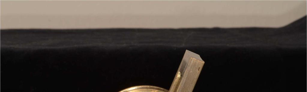
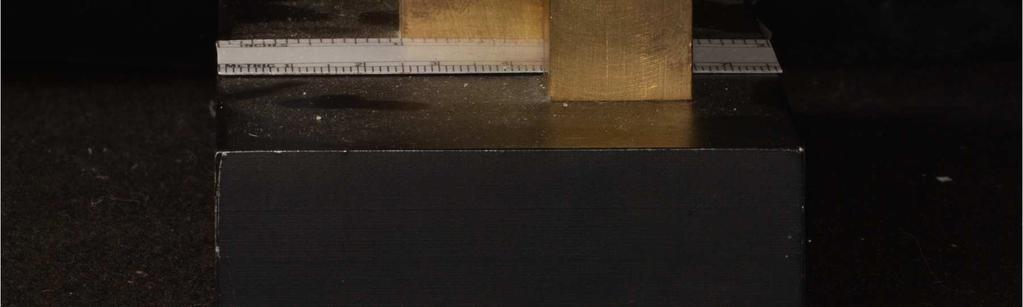
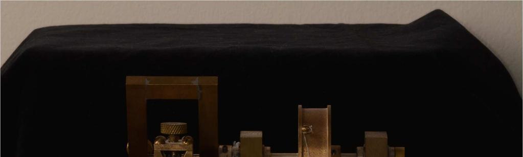
36 Figure 8. Photos of Torquing Machine 26


37 27


38 28
39 Base The base is constructed of one-inch thick steel. The weight of the steel will prevent unwanted movements during testing. The base dimensions are three inches by six inches. There is a one and a quarter inch groove one half inch thick through the base to allow access to the height adjustment screw of the bracket standard. Rotational Drive Mechanism The rotational drive mechanism consists of two supports that contain ball bearings within them, a two-inch wheel, and a drive shaft. The functions of the rotational drive mechanism are: to facilitate pure rotation of the brass wand, to provide a lever arm and link to the applied force via the two inch wheel, and to diminish frictional resistance to rotation. The two-inch wheel is secured to the drive shaft between the supports with a set screw. The drive shaft passes through the two bearings of the supports. The brass wand is secured to the end of the drive shaft as it extends past the support (Figures 6-8). Brass Wand The brass wand is attached to the drive shaft of the rotational drive mechanism. The functions of the brass wand are to enable secure attachment of both ends of the x inch wire and to permit pure rotation of the wire in the bracket slot. The wand is made of one-quarter inch square brass. The outside dimensions of the brass wand are one and three-quarters inch wide and four inches long. Midway along the wand are the holes for the three-sixteenth inch steel inserts which secure the x 29
40 0.025 inch wire. Adjustment screws are provided to stabilize the steel inserts. One adjustment screw is positioned on either side of the brass wand to help prevent unbalanced wand rotation (Figure 9). 30


")
 and")
41 Figure 9. Schemetic Drawing of the Brass Wand Assembly (Hillam 1990) Front view (Left) and side view (right). 31
42 Steel Inserts The steel inserts are constructed from a three-sixteenth inch steel rod. The inserts are one half inch long. The purposes of the steel inserts are to affix the x inch wire to the brass wand, and at the same time allow rotational adjustment of the wire along its long axis by rotation of the inserts in the brass wand. The steel inserts are fabricated specifically for a x inch wire. The base of the slot is milled inches past mid-shaft and the width of the cut is inches. Threads are tapped down through the milled slot for a set screw. This set screw forces the wire into the base of the slot and secures the wire into position. The inserts were positioned on both sides of the brass wand. The inner edges of the inserts are positioned as close to the bracket as possible without touching the mounting posts. This diminishes the possibility of wire distortions during testing by decreasing wire length (Figure 10). 32

 and")
43 Figure 10. Schemetic Drawing of the Steel Inserts (Hillam 1990) Cross sectional view (top) and longitudinal view (bottom) 33
44 Bracket Standard The bracket standard is fastened to the steel base and is located inside the brass wand. The functions of the standard are to hold the mounting posts and to allow full adjustability of the bracket. This permits the wire to be positioned passively into the bracket slot. The bracket standard consists of a male and female portion. The male portion is superior to the female portion. The male portion is constructed of three-quarter inch square brass with a one-quarter inch steel rod extending inferiorly. The upper part of the male portion secures the mounting post with three-point contact. The three-point contact is defined by the two walls of the V shaped notch in the upper compartment of the male portion and the set screw. The set screw tightens the post into place. The quarter inch steel rod extends down into the inferior female portion. A vertical adjustment screw (which is tapped through the base), contacts the inferior-most surface of the quarter inch vertical rod of the male portion. This allows accurate, finite vertical adjustments of the bracket. A set screw midway on the female portion secures the vertical and rotational position of the male portion. The female portion is constructed of three-quarter inch square brass. Two linear bearings are inserted into the female portion, one above the adjustment screw and one below it. This allows sure vertical and rotational adjustment of the bracket (Figure 11). 34


 35")

45 Figure 11. Schemetic Drawing of Bracket Standard (Hillam 1990) 35
46 Torque Measurement A protractor was modified to fit the machine so that angular measurements could be recorded for each test. A pointer was attached to the center of the brass wand to make measurements easier and more accurate to record (Figure 8). Placement of the Bracket into the Torquing Machine The steel inserts and x inch wire were initially adjusted in the brass wand so that the brass wand would assume a vertical position when the wire was fully seated in the bracket slot. The mounting post and bonded bracket were positioned into the upper compartment of the male part of the bracket standard. The mounting post was then positioned so that the gingival portion of the bracket was located superiorly. The bracket standard s adjustment screw was loosened to allow vertical linear and horizontal rotational adjustments. The vertical adjustment screw, located in the groove milled into the steel base, was used to calibrate the vertical height so that the wire fit passively into the bracket slot. The bracket standard adjustment screw was tightened only when the vertical height and horizontal rotation were confirmed. The mounting post s set screw was tightened only when the bracket was fully engaged into the base of the bracket s slot. (Figure 12) 36


47 Figure 12. Photo of Archwire Engaged in Bracket with Steel Inserts 37
48 Torque Determination The torque determination was done using a known weight. Lead weights were measured with a calibrated scale and attached to the two-inch rotational drive wheel with a strand of 25 pound test nylon line (Figure 16). Friction of the Torqueing Machine was determined by allowing an Instron Machine to record a full rotational cycle of the brass wand without a test specimen in place. The values at each half were recorded and an average was calculated. The average frictional resistance of the Torqueing Machine was 9.0 grams. Mathematical Determination Torque is expressed in orthodontics most correctly in Newton-millimeters (Nmm). All torque values will therefore be converted and expressed in Nmm. The conversion is as follows: From gram-millimeters to newton-millimeters: gm-mm x m/s 2 =Nmm Because the force applied to the two-inch wheel of the torqueing machine is at a right angle, the torque can be calculated by multiplying the force times the distance. The distance is the radius of the wheel (which is one inch or 25.4mm). The force is the lead weight determined for each test. To determine torque in gram-millimeters: 25.4mm x grams= gram-millimeters 38
49 This value is converted to newton-millimeters: gram-millimeters x m/s 2 =Nmm The actual force (in grams) to either the gingival or incisal wing can be mathematically calculated by determining the couple produced by the x inch wire in the bracket slot. Several statements regarding couple determination should be made: 1. Rotational tendency at the two-inch wheel equals that at the x inch wire. 2. A two force expollient couple is defined as having (1) the same total force and (2) the same total moment about the same moment center. The two equal but opposite forces cancel each other out. The equilibrium or motion of the body engaged by the expollient couple is due soley to the influence of a single force F, acting at O and a couple (or moment arm) M. [the force is delivered to the archwire by a weight hung from the Torquing Machine that rotates the archwire. The wand holding the archwire moves until the wire has reached an equilibrium position within the bracket slot. Theoretically the result is a pure rotation of the wand. The full rotation of the wand at equilibrium position represents the torque delivered to the wire by the force. 3. The scaler formulation of a couple is defined: Couple=Force x Distance. The force is the magnitude of one of the forces and the distance is the perpendicular distance or moment arm between the forces (Beer 1976). 39
50 4. Because the Torqueing Machine requires 9.0 grams of force to overcome friction, this amount was subtracted from each recorded force measurement. Applying the above statements the following equation was established: Fw x Dw= +Fb Db Where: Fw= selected lead weight at the two inch wheel. Dw= radius of the two inch wheel which is 25.4mm Fb= force from the bracket on wire Db= (0.782mm) the hypotenuse of the x inch wire. By dividing both sides of the equation by Db, the force of the couple can be calculated. Substituting the values for the hypotenuse (0.782mm) and the radius of the two inch wheel (one inch or 25.4mm) into the equation produces a constant of 32.38mm. Fw x Dw/Db=Fb Fw x 25.4mm/0.782mm=Fb Fw x 32.48mm=Fb Therefore, the lead weight (corrected for friction) times the constant equals the force applied by the x inch wire on either the gingival or incisal wings of the bracket. 40
51 For example: A 76 gram weight minus 9 grams for friction equals 67 grams. 67g x 32.48= 2176gmm. Converting this to Nmm by multiplying by m/s 2 = 21.35Nmm at the bracket. Archwire Alloy Selection Nitinol, TMA, and Stainless Steel archwires were selected to meet the exact criteria of the manufacture s specifications. All archwires were supposed to be x inches. It was possible to find Stainless Steel archwires to meet these exact specifications, but was not possible to find an exact match in either TMA or Nitinol. Archwires were measured with a caliper to get as close to manufacture s specifications; to once again remove as many variables as possible. Archwires proved to be highly variable (some too large and some too small) as predicted in previous research (Arreghini 2014). Overview of Statistical Methods Descriptive statistics were computed for the torque with wide and narrow brackets in three types of orthodontic archwires. Multiple tests were run under different loads and conditions, and the torque was recorded. Loads of 2.94Nmm, 4.91Nmm, 21Nmm were tested. A test was also conducted at the 21Nmm load with a narrow bracket with a modified tie wing that was the same as the tie wing of the wide brackets. This was done in order to reduce another variable. An additional test was conducted at the 21Nmm load in which the wire mount was modified in the narrow bracket to be the same distance from 41
52 the distal tie wing to the wire mount on either side. This distance was exactly matched to the distance from distal tie wing of wide bracket to wire mount on either side. This was done to reduce another variable. The torque represents the angle the archwire would need to be bent to, to achieve the desired clinical load at the root apex, which produces physiologic tooth movement. A paired-sample-t-test was used to detect the difference in torque between narrow and wide brackets within each type of archwire group. When considering the narrow and wide brackets separately, one-way ANOVA, followed by the post-hoc Tukey s HSD (Honestly Significant Difference) test, were used to test for the difference in torque among the three types of archwires. All tests utilized a 0.05 level of significance, and statistical analyses were performed using the statistical package SAS System version 9.4 (SAS Institute Inc., Cary, NC, USA). 42
53 RESULTS Fifteen.022X0.028 bracket slots were used in the study (n=5/per group). Descriptive statistics for the torque with wide and narrow brackets for 21Nmm torque are summarized in Table 2. Detecting the difference in torque with 21Nmm load between wide and narrow brackets within each type of archwire group. Stainless Steel Based on the paired-sample t-test, the data revealed that there was a significant difference in mean torque between narrow and wide brackets for the 21Nmm load within the Stainless Steel archwire group (p=0.0029). The mean torque difference between narrow and wide brackets was 4.4 (SD=1.52) degrees, and mean torque was 25.8 (SD=2.17) degrees for narrow brackets and 21.4 (SD=1.14) degrees for wide brackets (Table 1). TMA Based on the paired-sample t-test, the data revealed that there was a significant difference in mean torque between narrow and wide brackets for the 21Nmm load within the TMA archwire group (p=0.0001). The mean torque difference between narrow and wide brackets was 7.9 (SD=1.24) degrees, and mean torque was 33.9 (SD=2.19) degrees for narrow brackets and 26 (SD=1.73) degrees for wide brackets (Table 2). 43
54 Nitinol Based on the paired-sample t-test, the data revealed that there was a significant difference in mean torque between narrow and wide brackets with 21Nmm torque within the Nitinol archwire group (p<0.0001). The mean torque difference between narrow and wide brackets was 12 (SD=1.41) degrees, and mean torque was 38 (SD=1.22) degrees for narrow brackets and 26 (SD=0.71) degrees for wide brackets (Table 2). Detecting the difference in torque with wide and narrow brackets for 21Nmm load between three archwire groups For Wide Bracket Results of one-way ANOVA revealed that there was a significant effect for the archwire group on torque for the wide brackets with 21Nmm load (F(2,12)=22.04; p<0.0001), indicating a significant difference torque between the archwire groups. The post-hoc Tukey s HSD test revealed that the mean torque observed in the Stainless Steel archwire group was significantly lower than those observed in the TMA and Nitinol archwire groups, while no significant difference was found between TMA and Nitinol archwire groups. Table 2 provides detailed results from the post-hoc Tukey s HSD test. For Narrow Bracket Results of one-way ANOVA revealed that there was a significant effect for the type of archwires on torque for the narrow brackets with 21Nmm load (F(2,12)=52.56; p<0.0001), indicating a significant difference in torque between the three archwire groups. The post-hoc Tukey s HSD test revealed that mean torque for Nitinol was 44
55 significantly greater than those observed in the TMA and Stainless Steel archwire groups, while the mean torque observed in TMA was significantly greater than that observed in the Stainless Steel archwire group. Table 7 provides detailed results from the post-hoc Tukey s HSD test. Sixty 0.022X0.028 bracket slots were used in the study (n=5/per group). Descriptive statistics for the torque with wide and narrow brackets under different loads in (Nmm) are summarized in Tables 3 through 6. Evaluation of Torque with 4.91Nmm Load (1) Detecting the difference in torque with 4.91Nmm load between wide and narrow brackets within each archwire group Stainless Steel Based on the paired-sample t-test, no significant difference in torque was found between narrow and wide brackets for the 4.91Nmm load within the Stainless Steel archwire group (p=0.6885). The mean torque difference between narrow and wide bracket was 0.20 (SD=1.04) degrees (Table 3). TMA Based on the paired-sample t-test, no significant difference in mean torque was found between narrow and wide brackets for the 4.91Nmm load within the TMA archwire group (p=0.0641). The mean torque difference between narrow and wide brackets was 3.8 (SD=3.35) degrees (Table 3). 45
56 Nitinol Based on the paired-sample t-test, no significant difference in mean torque was found between narrow and wide brackets for the 4.91Nmm load within the Nitinol archwire group (p=0.1778). The mean torque difference between narrow and wide brackets was -1.6(SD=2.19) degrees (Table 3). Detecting the difference in torque with wide and narrow brackets for 4.91Nmm load between three archwire groups. Wide Bracket Results of one-way ANOVA revealed that there was a significant effect for the archwire group on the torque for the wide brackets with 4.91 Nmm load (F(2,12)=103.03; p<0.0001), indicating a significant difference in torque between the three archwire groups. The post-hoc Tukey s HSD test revealed that the mean torque was observed in the Nitinol archwire group was significantly greater than those observed in the TMA and Stainless Steel archwire groups, while the mean torque for the TMA archwire was significantly greater than that observed in the Stainless archwire. Table 8 provides detailed results from the post-hoc Tukey s HSD test. For Narrow Brackets Results of one-way ANOVA revealed that there was a significant effect for the archwire group on the torque for the narrow brackets with 4.91 Nmm load (F(2,12)=23.45; p<0.0001), indicating a significant difference in torque between the three archwire groups. The post-hoc Tukey s HSD test revealed that the mean torque observed in TMA and Nitinol archwire groups were significantly greater than those observed in the 46
57 Stainless Steel archwire group, while no significant difference was found between TMA and Nitinol archwire groups. Table 8 provides detailed results from the post-hoc Tukey s HSD test. Evaluation of Torque with 21Nmm Load with Modified Steel Inserts Narrow Brackets Detecting the difference in torque with 21Nmm load between wide and narrow brackets within each archwire group Stainless Steel Based on the paired-sample t-test, the data revealed that there was a significant difference in mean torque between narrow and wide brackets with 21Nmm load within the Stainless Steel archwire group (p=0.0086). The mean torque difference between narrow and wide brackets was 3.6 (SD=1.67) degrees, and mean torque was 25 (SD=1.0) degrees for narrow brackets and 21.4 (SD=1.14) degrees for wide brackets (Table 4). TMA Based on the paired-sample t-test, the data revealed that there was a significant difference in mean torque between narrow and wide brackets with 21Nmm load within the TMA archwire group (p=0.0111). The mean torque between narrow and wide brackets was 5.4 (SD=2.7) degrees, and mean torque was 31.4 (SD=1.52) degrees for narrow brackets and 26 (SD=1.73) degrees for wide brackets (Table 4). Nitinol Based on the paired-sample t-test, the data revealed that there was a significant difference in mean torque between narrow and wide brackets with 21Nmm load within 47
58 the Nitinol archwire group (p<0.0001). The mean torque between narrow and wide brackets was 8.8 (SD=0.84) degrees, and mean torque was 34.8 (SD=0.84) degrees for narrow brackets and 26 (SD=0.71) degrees for wide brackets (Table 4). Detecting the difference in torque with wide brackets and modified steel inserts narrow brackets for 21Nmm load between three archwire groups. Wide Bracket Results of one-way ANOVA revealed that there was a significant effect for the archwire groups on the torque for the wide brackets with 21Nmm load (F(2,12)=22.04; p<0.0001), indicating a significant difference in torque between the three archwire groups. The post-hoc Tukey s HSD test revealed that the mean torque observed in the TMA and Nitinol archwire groups were significantly greater than those observed in the Stainless Steel archwire group, while no significant difference was found between TMA and Nitinol archwire groups. Table 9 provides detailed results from the post-hoc Tukey s HSD test. Modified Narrow Brackets Results of one-way ANOVA revealed that there was a significant effect for the type of archwires on the torque for the modified narrow brackets with 21Nmm load (F(2,12)=92.85; p<0.0001), indicating a significant difference in torque between the three types of archwire groups. The post-hoc Tukey s HSD test revealed that the mean torque observed in the Nitinol archwire group was significantly greater than that observed in the Stainless Steel and TMA archwire groups, and the mean torque observed in the TMA 48
59 archwire group was significantly greater than that observed in the Stainless Steel archwire group. Table 9 provides detailed results from the post-hoc Tukey s HSD test. Evaluation of Torque with Narrow Brackets with 1mm Tie Wings for 21Nmm Load Detecting the difference in torque with 21Nmm load between wide and narrow brackets within each archwire group Stainless Steel Based on the paired-sample t-test, the data revealed that there was a significant difference in mean torque between narrow and wide brackets within the Stainless Steel archwire group (p=0.005). The mean torque difference between narrow and wide brackets was 4.3 (SD=1.72) degrees, and mean torque was 25.7 (SD=0.67) for narrow brackets and 21.4 (SD=1.14) degrees for wide brackets (Table 5). TMA Based on the paired-sample t-test, the data revealed that there was no significant difference in mean torque between narrow and wide brackets within the TMA archwire group (p=0.0542). The mean torque between narrow and wide brackets was 4.4 (SD=3.65) degrees, and mean torque was 30.4 (SD=2.61) degrees for narrow brackets and 26 (SD=1.73) degrees for wide brackets (Table 5). Nitinol Based on the paired-sample t-test, the data revealed that there was a significant difference in mean torque between narrow and wide brackets within the Nitinol archwire group (p<0.0001). The mean torque between narrow and wide brackets was
With judicious treatment planning, the clinical
 CLINICIAN S CORNER Selecting custom torque prescriptions for the straight-wire appliance Earl Johnson San Francisco, Calif Selecting custom torque prescriptions based on the treatment needs of each patient
Delta Force. Bracket System. Putting you in the driver s seat for ultimate control
 Delta Force Bracket System Putting you in the driver s seat for ultimate control Variable Force Orthodontics The Delta Force Bracket System incorporates an advanced design that allows you to control the
INDICATIONS. Fixed Appliances are indicated when precise tooth movements are required
 DEFINITION Fixed Appliances are devices or equipments that are attached to the teeth, cannot be removed by the patient and are capable of causing tooth movement. INDICATIONS Fixed Appliances are indicated
System Orthodontic Treatment Program By Dr. Richard McLaughlin, Dr. John Bennett and Dr. Hugo Trevisi
 A Clinical Review of the MBT Versatile+ Appliance System Orthodontic Treatment Program By Dr. Richard McLaughlin, Dr. John Bennett and Dr. Hugo Trevisi Treatment Philosophy of the MBT Appliance System
THE MBT VERSATILE+ APPLIANCE SYSTEM
 THE MBT VERSATILE+ APPLIANCE SYSTEM McLaughlin, Bennett, Trevisi The MBT Versatile+ Appliance System THE DEVELOPMENT OF A TREATMENT MECHANICS AND APPLIANCE PHILOSOPHY The first fully programmed preadjusted
Measurements of the torque moment in various archwire bracket ligation combinations
 European Journal of Orthodontics 34 (2012) 374 380 doi:10.1093/ejo/cjr022 Advance Access Publication 13 May 2011 The Author 2011. Published by Oxford University Press on behalf of the European Orthodontic
Controlled Space Closure with a Statically Determinate Retraction System
 Original Article Controlled Space Closure with a Statically Determinate Retraction System Kwangchul Choy, DDS, MS, PhD a ; Eung-Kwon Pae, DDS, MSc, PhD b ; Kyung-Ho Kim, DDS, MS, PhD c ; Young Chel Park,
Victory Series Active Self-Ligating Brackets. Reliable. and. Effective
 Victory Series Active Self-Ligating Brackets Reliable and Effective Victory Series Active Self-Ligating Brackets Reliability Victory Series SL Brackets are widely accepted as an industry benchmark for
MemRx Orthodontic Appliances
 MemRx Orthodontic Appliances Uses and Instructions The MemRx Fundamentals As the need for faster, more efficient treatment of non-compliant patients increases, orthodontic!technology and materials has
Archwire Insertion and Disengagement Instruments Technique Guide
 Clarity SL and SmartClip SL3 Self-Ligating Brackets Archwire Insertion and Disengagement Instruments Technique Guide Recommended Archwire Insertion Instruments Single point torquing key for tight spots
Enhanced Control in the Transverse Dimension using the Unitek MIA Quad Helix System by Dr. Sven G. Wiezorek
 Enhanced Control in the Transverse Dimension using the Unitek MIA Quad Helix System by Dr. Sven G. Wiezorek Dr. Wiezorek studied dental medicine at Kiel University, Germany from 1987 to 1993. He then finished
Advantages. Fantastic. Treatment. Finishes. 3M Self-Ligating Appliances Lateral Development System. Unitek Lateral Development Archwires
 3M Self-Ligating Appliances Lateral Development System Treatment Advantages Fantastic Finishes Adhesive Coated Appliance System Adhesive Coated Appliance System Unitek Lateral Development Archwires For
Advantages. Fantastic. systems. Together with Unitek Lateral Development Archwires, this system puts you in control to
 3M Self-Ligating Appliances Lateral Development System Treatment Advantages Fantastic Finishes For orthodontic professionals who choose lateral development as a desired treatment outcome, 3M now offers
The management of impacted
 Using a rigid hook and spring auxiliary slid onto the archwire to direct eruption of impacted teeth BY S. JAY BOWMAN, DMD, MSD, AND ALDO CARANO, DR ODONT, MS, SPEC ORTHOD Figure 1: A 12-year-old female
The Tip-Edge appliance and
 Figure 1: Internal surfaces of the edgewise archwire slot are modified to create the Tip-Edge archwire slot. Tipping surfaces (T) limit crown tipping during retraction. Uprighting surfaces (U) control
TURN CLASS II INTO SIMPLE CLASS I PATIENTS.
 TURN CLASS II INTO SIMPLE CLASS I PATIENTS. THE CARRIERE MOTION TM APPLIANCE fast gentle natural The Carriere Philosophy. Fast. Shortens overall treatment time by up to four months as it treats Class II
Plus Combines Traditional Twin Bracket Treatment With Self-Ligation Convenience
 Lotus Plus Combines Traditional Twin Bracket Treatment With Self-Ligation Convenience Designed by an Orthodontist The initial concept for the Lotus Plus Self-Ligating Bracket System started with a simple
The Tip-Edge Concept: Eliminating Unnecessary Anchorage Strain
 Welcome Ron Not Ron? Click here. My Account The Tip-Edge Concept: Eliminating Unnecessary Anchorage Strain VOLUME 26 : NUMBER 03 : PAGES (165-178) 1992 CHRISTOPHER K. KESLING, DDS, MS Tooth movement in
Table of Contents Section 6 Table of Contents
 Table of Contents Section 6 Table of Contents bands and attachments 6 3M Victory Series First Molar Bands... 6.2 3M Victory Series Second Molar Bands... 6.6 3M Unitek General Purpose Molar Bands... 6.10
The Rondeau System. Brackets, Bands, Buccal Tubes and Archwires. Orthodontic supplies recommended by Dr. Brock Rondeau
 The Rondeau System Brackets, Bands, Buccal Tubes and Archwires Orthodontic supplies recommended by Dr. Brock Rondeau Achieve Consistently Accurate Placement The Di-MIM Mini-Twin Bracket s rhomboid shape
Experience with Contemporary Tip-Edge plus Technique A Case Report.
 IOSR Journal of Dental and Medical Sciences (IOSR-JDMS) e-issn: 2279-0853, p-issn: 2279-0861. Volume 13, Issue 3 Ver. I. (Mar. 2014), PP 12-17 Experience with Contemporary Tip-Edge plus Technique A Case
Integrative Orthodontics with the Ribbon Arch By Larry W. White, D.D.S., M.S.D.
 Integrative Orthodontics with the Ribbon Arch By Larry W. White, D.D.S., M.S.D. Abstract The ribbon arch previously had great popularity and utility early in the 20 th century, but lost its appeal as edgewise
Bands and Attachments
 RxWeld Service Custom Services Convenient prescription program for orthodontists who reorder 3M Unitek seamless bands prewelded with 3M Unitek attachments Reduces reorder time and paperwork Eliminates
Gentle-Jumper- Non-compliance Class II corrector
 15 CASE REPORT Gentle-Jumper- Non-compliance Class II corrector Amit Prakash 1,O.P.Mehta 2, Kshitij Gupta 3 Swapnil Pandey 4 Deep Kumar Suryawanshi 4 1 Senior lecturer Bhopal - INDIA 2 Professor Bhopal
Anchorage system. tomas / Sets Page 270 tomas / Pins Page 271 Instruments and accessories Page 273 Patient consultation material Page 282
 tomas / Sets Page 270 tomas / Pins Page 271 Instruments and accessories Page 273 Patient consultation material Page 282 266 . innovative comprehensive efficient. Dentaurum Online Shop shop.dentaurum.com
6. Timing for orthodontic force
 6. Timing for orthodontic force Orthodontic force is generally less than 300gm, so early mechanical stability is enough for immediate orthodontic force. There is no actually difference in success rate
Introducing the Clarity SL Self-Ligating Appliance System
 Introducing the Clarity SL Self-Ligating Appliance System Lunch and Learn Agenda Clarity SL Brackets Overview Consultation Benefits Bracket Positioning Benefits Bonding Benefits Leveling & Aligning Benefits
wiirre e a a n n d d w wiirre e ffo orrms ms
 wire and wire forms wire and wire forms wire and wire forms Leone orthodontic wires are available in a range of alloys and different grades of elasticity and hardness to meet any therapeutic requirements.
(12) Patent Application Publication (10) Pub. No.: US 2005/ A1
 Patent Application Publication (10) Pub. No.: US 2005/ A1") (19) United States US 2005O130094A1 (12) Patent Application Publication (10) Pub. No.: US 2005/0130094A1 Graham (43) Pub. Date: Jun. 16, 2005 (54) ORTHODONTIC ACCESSORY ARCH BAR (52) U.S. Cl.... 433/20
(19) United States US 2005O130094A1 (12) Patent Application Publication (10) Pub. No.: US 2005/0130094A1 Graham (43) Pub. Date: Jun. 16, 2005 (54) ORTHODONTIC ACCESSORY ARCH BAR (52) U.S. Cl.... 433/20
Surveying. 3rd year / College of Dentistry/University of Baghdad ( ) Page 1
 Page 1") د. فائزة Lec.3 Prosthodontics Surveying The ideal requirements for successful removable partial denture are: 1. Be easily inserted and removed by the patient. 2. Resist dislodging forces. 3. It should
د. فائزة Lec.3 Prosthodontics Surveying The ideal requirements for successful removable partial denture are: 1. Be easily inserted and removed by the patient. 2. Resist dislodging forces. 3. It should
ANTERIOR AND CANINE RETRACTION: BIOMECHANIC CONSIDERATIONS. Part One
 In italiano, per favore ANTERIOR AND CANINE RETRACTION: BIOMECHANIC CONSIDERATIONS Part One Gabriele Floria DDS, Lorenzo Franchi DDS, Turi Bassarelli MD English Translation by Dr. Susan Eslambolchi & Dr.
The 20/20 Molar Tube. Ronald M. Roncone, D.D.S., M.S.
 The 20/20 Molar Tube by Ronald M. Roncone, D.D.S., M.S. A) Finish torque STAGE 3: Interactive to Active GOALS 4-6 months B) Finish root uprighting C) Maintain arch form D) Set occlusion with active settling
Use of a Tip-Edge Stage-1 Wire to Enhance Vertical Control During Straight Wire Treatment: Two Case Reports
 Case Report Use of a Tip-Edge Stage-1 Wire to Enhance Vertical Control During Straight Wire Treatment: Two Case Reports Helen Taylor, BDS, MScD, DOrth, MOrth, FDSRCS(Eng) a Abstract: Vertical control is
Simply Great Wire! Great prices.
 2017 CATALOG Simply Great Wire! Great prices. CONTENTS 2-4 NiTi Wires 5 Stainless Steel Wires 6-7 Archforms 8 Beta Titanium Molybdenum Wires 9 Wire Auxiliaries WWW.HIGHLANDMETALS.COM NiTi Wires SuperElastic
Keeping all these knowledge in mind I will show you 3 cases treated with the Forsus appliance.
 Due to technical difficulties there were some audio problems with the webinar recording. Starting at 27:54, please use this guide to follow along with Dr. Kercelli s presentation. Keeping all these knowledge
ORTHODONTIC BANDING AND CEMENTATION. Materials
 ORTHODONTIC BANDING AND CEMENTATION Materials Required Materials for fitting bands: 1. Selection of bands of different sizes for the teeth to which you are fitting bands 2. Tweezers to take the bands out
04 Inserting the HYCON TUBE
 H y c o n D e v i c e f o r s p a c e c l o s u r e hycon HYCON t u b e placement information TUBE placement information 01 The HYCON TUBE block. The teeth of the front block should be laced with a figure
A New Fixed Interarch Device for Class II Correction
 A New Fixed Interarch Device for Class II Correction WILLIAM VOGT, DDS Fixed devices are increasingly being used for molar distalization in Class II treatment because they eliminate the need for special
SnapLink Re-Convertible Tube
 SnapLink Re-Convertible Tube Background Buccal tubes are attached to the upper and lower molars to anchor the distal ends of archwires, or to attach an auxiliary wire, headgear or lip bumper, or as an
A THESIS SUBMITTED TO THE FACULTY OF THE GRADUATE SCHOOL OF THE UNIVERSITY OF MINNESOTA BY
 THE EFFECTIVENESS OF SURESMILE TECHNOLOGY TO ACHIEVE PREDICTED TREATMENT OUTCOME A THESIS SUBMITTED TO THE FACULTY OF THE GRADUATE SCHOOL OF THE UNIVERSITY OF MINNESOTA BY CHRISTOPHER JOHN VAUBEL IN PARTIAL
3M Incognito Appliance System extraction case study.
 SM 3M Health Care Academy 3M Incognito Appliance System extraction case study. Toru Inami, DDS, Ph.D. Dr. Toru Inami graduated from the Aichigakuin University School of Dentistry in 1976. From 1977 to
Dual Force Cuspid Retractor
 CLINICAL INNOVATION 1 Matrishva B Vyas, 2 Neeraj Alladwar ABSTRACT The most time consuming stage of bicuspid extraction-based treatment is cuspid retraction. Cuspid retraction with both types of conventional
TURN CLASS II INTO SIMPLE CLASS I PATIENTS.
 TURN CLASS II INTO SIMPLE CLASS I PATIENTS. THE CARRIERE MOTION TM APPLIANCE fast gentle natural The Carriere Philosophy. Fast. Shortens overall treatment time by up to four months as it treats Class II
Measurement of Forces and Moments in Three- Dimensional Archwires
 Virginia Commonwealth University VCU Scholars Compass Theses and Dissertations Graduate School 2003 Measurement of Forces and Moments in Three- Dimensional Archwires Dwight Van Buelow Virginia Commonwealth
3D CONTROL HAS ARRIVED
 TM 3D CONTROL HAS ARRIVED 1 Pitts 21 Self-Ligating System Pitts 21 Self-Ligating System Integrated Hooks An available option on the 3 s, 4 s and 5 s for your convenience at no extra charge. Smooth, Rounded
Mollenhauer Aligning Auxiliary for Bodily Alignment of Blocked-out Lateral Incisors in Preadjusted Edgewise Appliance Therapy
 Original Research 10.5005/jp-journals-10021-1237 Mollenhauer Aligning Auxiliary for Bodily Alignment of Blocked-out Lateral Incisors in Preadjusted Edgewise Appliance Therapy 1 Sreekrishnan B Nair, 2 AT
INTRAORAL / EXTRAORAL. tportho.com cosmeticbraces.com. POD_TPOC_06_Intraoral_Extraoral_2017, Rev. 1
 6 INTRAORAL / EXTRAORAL tportho.com cosmeticbraces.com POD_TPOC_06_Intraoral_Extraoral_2017, Rev. 1 INTRAORAL / EXTRAORAL Coated Crimpable Hook Standard Aesthetic Ribbed Crimpable Hook Standard Aesthetic
Managing. Not on course. Unplanned reaction 9/15/2011. Possible Reactions. Probable Root causes. invisalign Aligner Tracking Issues
 Managing invisalign Aligner Tracking Issues Tips and Techniques for keeping treatment on course Dr. Karol Miranda DDS Universidad Latino Americana de Ciencia y Tecnología, (ULACIT), Costa Rica. Private
Canine Extrusion Technique with SmartClip Self-Ligating Brackets
 Canine Extrusion Technique with SmartClip Self-Ligating Brackets Dr. Luis Huanca Ghislanzoni Dr. Luis Huanca received his DDS in 2006 and the MS and Specialist in Orthodontics in 2009 from the University
Lab Forms and Communications Precise Indirect Bonding Systems.
 Lab Forms and Communications Precise Indirect Bonding Systems. Presented by IN-tendo www.intendo-ortho.com and The Torque Angulation Laboratory www.torque-angulationlab.com The correct information and
Archwires & Accessories
 Archwires & Accessories Orthodontic products-catalog 01 55 Archwires and Accessories Summary Archwire Shapes 58 Initialloy 59 BioEdge 60 BioActive 61 Reverse Curve 62 Beta Titanium 62 Stainless Steel Archwires
Characterizing constraining forces in the alignment phase of orthodontic treatment
 Original Article Characterizing constraining forces in the alignment phase of orthodontic treatment Christopher G. Gibson a ; Feng-Chang Lin b ; Ceib Phillips c ; Alex Edelman d ; Ching-Chang Ko e ABSTRACT
Forsus Class II Correctors as an Effective and Efficient Form of Anchorage in Extraction Cases
 Forsus Class II Correctors as an Effective and Efficient Form of Anchorage in Extraction Cases by Lisa Alvetro, DDS, MSD After receiving her DDS summa cum laude from Ohio State University, Dr. Alvetro
AlignEUSummit2015_PPT Template- GEN SESSION_
 Innovations of Invisalign Clear Aligners John Morton Director of Research and Technology 1 2016 Align Technology, Inc. All rights reserved. Legal Disclaimer The statements, views and opinions expressed
Interdisciplinary management of Impacted teeth in an adult with Orthodontics & Free Gingival graft : A Case Report
 Original article: Interdisciplinary management of Impacted teeth in an adult with Orthodontics & Free Gingival graft : A Case Report Dr Renuka Patel, Dr Falguni Mehta, Dr. Ashish Pandey Assistant Professor,
Replacing Missing or Debonded Brackets
 CFAST Help Sheet Replacing Missing or Debonded Brackets Brackets becoming deboned are not uncommon you will almost certainly experience this. The important thing to remember is - DON T PANIC! And tell
Technique Guide. Orthodontic Bone Anchor (OBA) System. Skeletal implants for the orthodontic movement of the teeth.
 System. Skeletal implants for the orthodontic movement of the teeth.") Technique Guide Orthodontic Bone Anchor (OBA) System. Skeletal implants for the orthodontic movement of the teeth. Table of Contents Introduction Orthodontic Bone Anchor (OBA) System 2 Indications and
Technique Guide Orthodontic Bone Anchor (OBA) System. Skeletal implants for the orthodontic movement of the teeth. Table of Contents Introduction Orthodontic Bone Anchor (OBA) System 2 Indications and
Clarity. Form meets function: Discover the science behind a versatile self-ligating bracket system. Aesthetic Orthodontic Solutions
 Clarity Aesthetic Orthodontic Solutions Form meets function: Discover the science behind a versatile self-ligating bracket system Armineh Khachatoorian Scientific Affairs Manager 3M Oral Care Rethink your
REPRINTED FROM JOURNAL OF CLINICAL ORTHODONTICS 1828 PEARL STREET, BOULDER, COLORADO Dr. Nanda Dr. Marzban Dr. Kuhlberg
 REPRINTED FROM JOURNAL OF CLINICAL ORTHODONTICS 1828 PEARL STREET, BOULDER, COLORADO 80302 Dr. Nanda Dr. Marzban Dr. Kuhlberg Dr. Nanda is Professor, Head, and Program Director, Dr. Marzban is a thirdyear
Crowded Class II Division 2 Malocclusion
 Class II Division 2 Malocclusion Crowded Class II Division 2 Malocclusion Clinicians: Drs. Chris Chang, Hsin-Yin Yeh, Sophia Pei-Wen Shu, W. Eugene Roberts Patient: Miss Jhan Pre-treatment Diagnosis An
Space Closure Biomechanics Applied Using The MBT System Technique
 Space Closure Biomechanics Applied Using The MBT System Technique by Hugo Trevisi, D.D.S. Dr. Hugo Trevisi, São Paulo, Brazil Dr. Hugo Trevisi received his dental degree in 1974 at Lins College of Dentistry
Bracket Systems. A good bracket is the foundation of a good treatment plan... Go ahead, choose the best. Metal Bracket.
 A good bracket is the foundation of a good treatment plan... Go ahead, choose the best. Metal Bracket Self Ligating System Precimax Iridium Econo Lingual Bracket Aesthetic Bracket Cerabrace Krystal Ice
GREAT LAKES BRACKETS. Treat with Quality. Treat with Confidence.
 GREAT LAKES BRACKETS Treat with Quality. Treat with Confidence. BRACKET SYSTEMS DESIGNED BY ORTHODONTISTS, FOR ORTHODONTISTS, GREAT LAKES BRACKETS DELIVER. EVERY SINGLE BRACKET IS HAND INSPECTED AND ENGINEERED
ORTHOdontics SLIDING MECHANICS
 ORTHOdontics PGI/II SLIDING MECHANICS FOCUS ON TARGETED SPACE GAINING AND ITS APPLICATIONS, INCLUDING WITH RAPID PALATAL EXPANDIONS. ALSO INCLUDES RETENTION AND CLINICAL PEARLS FACULTY: Joseph Ghafari,
SURVEYING OF REMOVABLE PARITAL DENTURES FEB, 11, 2015
 SURVEYING OF REMOVABLE PARITAL DENTURES FEB, 11, 2015 Dental Surveyor: It is a mechanical device used to determine the relative parallelism of the teeth surfaces and the undercuts areas in relation to
CLASS II CORRECTION SIMPLIFIED
 C L A S S I I C O R R E C T O R CLASS II CORRECTION SIMPLIFIED PowerScope 2 delivers simple, efficient Class II correction like you ve never seen before. The latest generation of PowerScope features a
Advanced Probing Techniques
 Module 21 Advanced Probing Techniques MODULE OVERVIEW The clinical periodontal assessment is one of the most important functions performed by dental hygienists. This module begins with a review of the
rocky mountain orthodontics functionaleducation
 rocky mountain orthodontics 3D 1ST PHASE FIXED/REMOVABLE (WILSON ) Without changing your chosen technique, RMO 3D 1st Phase FIXED/REMOVABLE Modular Orthodontics TM (Wilson ) can help your practice target
Aesthetic Brackets and Accessories
 Aesthetic Brackets and Accessories Our Strength is our Service Ortho-Care s version of the MBT prescription shown in this chapter is not claimed to be a duplication, and does not in any way imply endorsement
MBT System as the 3rd Generation Programmed and Preadjusted Appliance System (PPAS) by Masatada Koga, D.D.S., Ph.D
 by Masatada Koga, D.D.S., Ph.D") MBT System as the 3rd Generation Programmed and Preadjusted Appliance System (PPAS) by Masatada Koga, D.D.S., Ph.D Dr. Masatada Koga, D.D.S., Ph.D, is an assistant professor in the Department of Orthodontics
MBT System as the 3rd Generation Programmed and Preadjusted Appliance System (PPAS) by Masatada Koga, D.D.S., Ph.D Dr. Masatada Koga, D.D.S., Ph.D, is an assistant professor in the Department of Orthodontics
History of NiTinol. Ni = Nickel Ti = Titanium N = Naval O = Ordnance L = Laboratory
 History of NiTinol Ni = Nickel Ti = Titanium N = Naval O = Ordnance L = Laboratory NiTinol was discovered in a laboratory of the U.S. Marines in 1962 (US-Naval Ordnance Laboratory). The U.S. Marines wanted
Mx1 to NA = 34 & 10 mm. Md1 to NB = 21 & 3 mm.
 Chapter 16 Clinical cases: mixed dentition and adolescent, CLII non-extraction 219 Full CLII div I OJ = 15 OB = 8 SNA = 82 SNB = 75 Mx1 to NA = 34 & 10 mm. Md1 to NB = 21 & 3 mm. Md1 to A-pog = -2 GO-GN
KEY TO VECTOR FORCES:
 by V. C. Bud White DDS, MS KEY TO VECTOR FORCES: QUALITATIVE VECTOR FORCES-RED QUANTITATIVE VECTOR FORCES-GREEN RESULTANT TOOTH MOVEMENTS CROWN/ROOT-BLACK A vector force is a resolution of all the forces
Orthodontic Product Catalog
 Orthodontic Product Catalog ceramic brackets 1 self-ligating appliances 2 metal brackets 3 3M Vision 3M Technology Advancing Every Company 3M Products Enhancing Every Home 3M Innovation Improving Every
SmartForce features and Attachments. Designed to help you treat with confidence.
 SmartForce features and s. Designed to help you treat with confidence. SmartForce features and s. SmartForce Features are: Engineered to deliver the force systems necessary to achieve more predictable
Treatment of Class II, Division 2 Malocclusion in Adults: Biomechanical Considerations FLAVIO URIBE, DDS, MDS RAVINDRA NANDA, BDS, MDS, PHD
 REPRINTED FROM JOURNAL OF CLINICAL ORTHODONTICS 1828 PEARL STREET, BOULDER, COLORADO 80302 Treatment of Class II, Division 2 Malocclusion in Adults: Biomechanical Considerations FLAVIO URIBE, DDS, MDS
An Effectiv Rapid Molar Derotation: Keles K
 An Effectiv ective e and Precise Method forf Rapid Molar Derotation: Keles K TPA Ahmet Keles, DDS, DMSc 1 /Sedef Impar, DDS 2 Most of the time, Class II molar relationships occur due to the mesiopalatal
Checklist with summary points
 Checklist with summary points Question 1: Are your doctor Invisalign preferences on your home page up to date? Go to your doctor home page and open up your doctor preferences pages. Be sure to update item
Comparative analysis of load/deflection ratios of conventional and heat-activated rectangular NiTi wires
 Comparative analysis of load/deflection ratios of conventional and heat-activated rectangular NiTi wires Fabio Schemann-Miguel 1, Flávio Cotrim-Ferreira 2, Alessandra Motta Streva 3, Alexander Viégas de
Maxillary central incisor crown-root relationships in class I normal occlusions and class III open and deep malocclusions
 University of Iowa Iowa Research Online Theses and Dissertations Spring 2015 Maxillary central incisor crown-root relationships in class I normal occlusions and class III open and deep malocclusions Jessica
HYCON Device. Fast, precise and successful space closure made easy! 25 years - around the globe research - design - manufacturing - distribution
 SMART INNOVATION HYCON Device Fast, precise and successful space closure made easy! 25 years - around the globe research - design - manufacturing - distribution 2 The HYCON Device SMART INNOVATION Fast,
Low-Force Mechanics Nonextraction. Estimated treatment time months (Actual 15 mos 1 week). Low-force mechanics.
. Low-force mechanics.") T.S. Age: 43 Years 1 Month Diagnosis: Class I Nonextraction Adult (severe crowding, very flat profile with tissue-grafting indications) Background: This case is very similar to the previous case of a 14-year-old.
T.S. Age: 43 Years 1 Month Diagnosis: Class I Nonextraction Adult (severe crowding, very flat profile with tissue-grafting indications) Background: This case is very similar to the previous case of a 14-year-old.
The effect of Gable angle size and spring activation distance of 0.016x0.022 NiTi and TMA sectional T-loop towards force, moment y.
 Padjadjaran Journal of Dentistry 2009;21(2):78-87. The effect of angle size and spring activation distance of 0.016x0.022 NiTi and TM sectional T-loop towards force, moment y values Norman Wachyudi, Tono
A finite element analysis of the effects of archwire size on orthodontic tooth movement in extraction space closure with miniscrew sliding mechanics
 Kawamura and Tamaya Progress in Orthodontics (2019) 20:3 https://doi.org/10.1186/s40510-018-0255-8 RESEARCH Open Access A finite element analysis of the effects of archwire size on orthodontic tooth movement
A Modified Three-piece Base Arch for en masse Retraction and Intrusion in a Class II Division 1 Subdivision Case
 Dhaval Ranjitbhai Lekhadia, Gautham Hegde RESEARCH ARTICLE 10.5005/jp-journals-10029-1149 A Modified Three-piece Base Arch for en masse Retraction and Intrusion in a Class II Division 1 Subdivision Case
Unilateral Horizontally Impacted Maxillary Canine and First Premolar Treated with a Double Archwire Technique
 Case Report Unilateral Horizontally Impacted Maxillary Canine and First Premolar Treated with a Double Archwire Technique Chien-Lun Peng a ; Yu-Yu Su b ; Sheng-Yang Lee c Abstract: A patient with a unilateral
BOCL-01: Bonding Materials Checklist
 Task 19: Gather materials to bond partner using toothpaste as etchant Take a photo of gathered materials and submit with this completed checklist BOCL-01: Bonding Materials Checklist Date: Patient: Operator:
HYCON DEVICE: A PRECISE AND CONTROLLED METHOD OF SPACE CLOSURE A CASE REPORT
 HYCON DEVICE: A PRECISE AND CONTROLLED METHOD OF SPACE CLOSURE A CASE REPORT Authors: Dr Arun Kumar G a Master of Dental Surgery(Orthodontics) Associate Professor, Department of Orthodontics & Dentofacial
Principles of. By: Dr. Ahmad Rabah
 Principles of By: Dr. Ahmad Rabah 1. Utilize what's present: Whenever possible, select a design that fits the teeth and soft tissues, rather than choosing one that requires tissue alteration. When minimal
Class II. Bilateral Cleft Lip and Palate. Clinician: Dr. Mike Mayhew, Boone, NC Patient: R.S. Cleft Lip and Palate.
 Bilateral Cleft Lip and Palate Clinician: Dr. Mike Mayhew, Boone, NC Patient: R.S. Class II Cleft Lip and Palate Pretreatment Diagnosis Class II dolichofacial female, age 22 years 11 months, presented
LINGUAL STRAIGHTWIRE BRACKET SYSTEM Designed with Drs. Kyoto Takemoto and Giuseppe Scuzzo
 LINGUAL STRAIGHTWIRE BRACKET SYSTEM Designed with Drs. Kyoto Takemoto and Giuseppe Scuzzo THE WORLD S FIRST SELF-LIGATING SQUARE SLOT BRACKET Simplicity I Efficiency I Comfort ALIAS LINGUAL BRACKET SYSTEM
SE NiTi Heat Activated NiTi Ultra T Heat Activated NiTi Stainless Steel Beta Titanium. Ultra T Archwires
 S1:1 170421 7390 SOLITAIRE Single Pack s OrthoQuest offers the highest quality wires available in the orthodontic industry. Our wires are designed to exact specifications by trained engineers and manufactured
BRACKET CHOICES SYSTEM CHOICES. Empower 2 reconvertible molar tubes provide versatility without compromise.
 IT S ALL ABOUT CHOICE Empower is the industry s most complete self ligating bracket system, bringing you choice like you ve never had before. The Empower family includes bracket and system options that
Table of Contents Section 7 Table of Contents
 Table of Contents Section 7 Table of Contents archwire products 7 3M Unitek Nitinol Heat-Activated Archwire... 7.6 3M Unitek Nitinol Super-Elastic Archwire... 7.7 3M Unitek Nitinol Classic Archwire...
invisibles feature Chief Concern: I don t like the way my teeth look. I ll do braces, but would rather not.
 by Jonathan Nicozisis, DMD, MS Chief Concern: I don t like the way my teeth look. I ll do braces, but would rather not. Highlights of This Case: Invisalign used to correct an anterior crossbite with favorable
GAC Archwire Collection
 GAC Archwire Collection All the Metal That Matters Copper to Nickel and All Points In-Between Your choice in archwires is a critical decision in your quest for excellence. GAC has been recognized as a
Introduction. Formerly known as Susan David
 European Journal of Orthodontics 20 (1998) 589 596 1998 European Orthodontic Society A comparative in vitro study of the frictional characteristics of two types of self-ligating brackets and two types
What is Kinesiology? Basic Biomechanics. Mechanics
 What is Kinesiology? The study of movement, but this definition is too broad Brings together anatomy, physiology, physics, geometry and relates them to human movement Lippert pg 3 Basic Biomechanics the
essentialstm cutting your consumable costs brackets tubes wires springs instruments T:
 2017 essentialstm cutting your consumable costs brackets tubes wires springs instruments T: W: www.tocdental.com www.tocdental.com 1 Value Stainless Steel Brackets Manufactured from advanced 17-4 stainless