AccuVision Minimally Invasive Spinal Exposure System
|
|
|
- Sophie Stone
- 5 years ago
- Views:
Transcription

1 Surgical Technique AccuVision Minimally Invasive Spinal Exposure System Working Beyond the Tube Lighted blades for superior viewing Maximum stabilization

2 Contents Introduction... Page 1 Features and Benefits... Page 2 Instruments... Page 3 Surgical Technique... Page 5 Posterior Fixation With... Page 12 Polaris 5.5 Pedicle Screws AccuVision Frame Removal and Closure... Page 18 Indications for Use... Page 19 Sterilization Recommendations... Page 20 Ordering Information... Page 21 Further Information... Page 22 B
3 Introduction Biomet Spine is proud to present the AccuVision Minimally Invasive Spinal Exposure System. The AccuVision System has been designed to offer a variable approach to lumbar fixation for the ever-growing Minimally Invasive approach to spine surgery. The AccuVision System features a Retractor frame with a series of blades, shims and retractor modules that provide exceptional exposure to the bony anatomy, while utilizing the widely accepted Modified-Wiltse, Paraspinous approach to Spinal Surgery. The design goals for the AccuVision System were simple; provide a familiar modular, variable approach to minimally invasive spine surgery while maximizing the exposure to the anatomy. The ergonomically designed frame allows the surgeon to perform both non-fusion and fusion procedures with minimal change to the surgeon s individual technique. 1
4 Features and Benefits Features Minimal Skin Incision Mechanical Retraction System Variable Blade Lengths Stable Platform Benefits Less trauma to musculature around the spine Provides ample retraction up to four directions Steerable medial/lateral exposure without changing table/frame attachments Maximal exposure with minimal incision Custom fit system based on patient anatomy Provides the surgeon optimized work space without fiddle factor or floating of the frame in the surgical site 2
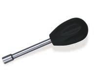
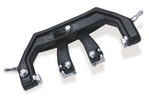
5 Instruments Retractor Frame Retractor Blades Shim Advancer Retractor Arms Shim Retractor Retractor Arms Retractor Wrench 3
")


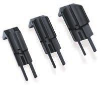
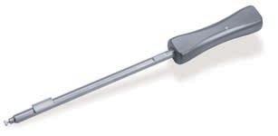
6 Instruments (Continued) Disposable Blade Tips (Lighted and Non-Lighted) Articulating Arm Radial Setting Clamp Dilators 4

7 Surgical Technique Patient Positioning and Pre-Operative Planning The patient is positioned prone in the surgeon preferred position for a posterior approach to spine surgery. Utilize fluoroscopic imaging to confirm necessary visualization of surgical size. The patient is then prepared and draped according to surgeon preference. Utilizing anterior/posterior and lateral fluoroscopy imaging and palpation of the patient s appropriate vertebral landmarks, the incision line is identified 2 to 4 cm lateral to the midline as directed by the surgeon for the indicated surgical procedure. O.R. Tips As part of pre-operative planning, a spinal needle or guide wire can be used to confirm location and trajectory for targeting the pedicle entry point - Discectomy/Non-Fusion Procedures: The target area is the lower aspect of the lamina overlying disc space to be accessed - Fusion Procedures: The target area is midway between the cephalad and caudal pedicle at the level to be fused To perform a contralateral decompression through a single sided approach, the target area should be similar to the approach described above for a fusion procedure For a two-level decompression, target the middle vertebrae - E.G. L3 to L5 laminectomy, target over the middle of L4 vertebrae 5
 should be performed to mobilize deep soft tissue off the bony anatomy and to achieve an accurate estimate of the tissue depth.")

 dilator or the 25mm (blue) dilator dependent upon surgeon preference. O.R.")
8 Surgical Technique (Continued) Incision and Exposure A Gentle sweeping of the first dilator (7.0mm diameter) should be performed to mobilize deep soft tissue off the bony anatomy and to achieve an accurate estimate of the tissue depth. Access to the bony aspect of the posterior spinal anatomy is initiated with a knife incision of the skin at the side and level of the spine requiring exposure for the prescribed procedure. An incision of the fascia overlying the muscle groups is also performed to assist the exposure process. The length of the skin incision line will be dictated by the amount of anatomy needing exposure. O.R. Tips The incision should be further lateral to the mid-line as the distance between the skin and posterior elements increases NOTE: The length of the fascia release can extend beyond the length of the skin incision. Subsequent sequential dilation can either be performed to the 18mm (yellow) dilator or the 25mm (blue) dilator dependent upon surgeon preference. O.R. Tips Following the sequential dilation, remove the dilators and utilize a Cobb elevator to scrape the soft tissue off the posterior elements and re-dilate The correct blade length can be determined via the following method: After the skin incision and fascia release have been completed, sequential dilation of the opening through the muscles is performed. - Sound with the first sequential dilator (7.0mm diameter) into the operative site, using the depth markings to determine blade depth. If the depth is between two markings, utilize the shorter blade 6


9 Attachment of Blade Tips: Articulating Arm Tips: Select the appropriate shape disposable blade and line up the channels of the blade to the posts of the reusable blade. Slide the shim retractor down the channel of the blade and align the T into the hole at the proximal end of the blade tip. Turn the handle of the shim retractor 90 and the spring-loaded instrument will pull the blade up. The AccuVision System comes with the option of attaching lighted or non-lighted blade tips to the individual retractor blades. With this in mind, pre-plan your retraction as necessary to determine where a lighted blade(s) would be necessary to aid in the visualization of the anatomy. The blade assembly can now be loaded into the appropriate parts of the AccuVision Frame. The blade is loaded by aligning the Male T at the proximal portion of the blade to the Female T Slot on the appropriate blade arms. Simply slide the blade into the retaining feature of the arms until an audible click is heard. Light Source Information: AccuVision Lighted Blade Tips are sterile packed with a standard ACMI Adapter. To connect to the O.R. supplied light source, a sterilized light cable needs to be supplied by the O.R. Do NOT connect the lighted blade tip directly to the light source. NOTE: the curved portion of the blade should always be facing towards the center of the frame. To remove the blade from the individual arms, press on the tab of the retaining feature, and pull the blade straight back from the arm. 7

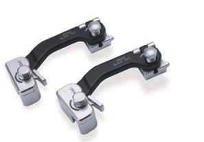
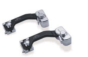
10 Surgical Technique (Continued) Articulating Arm and AccuVision Frame Configuration Assembly of Articulating Arm: Determine whether the articulating arms will be situated on either the surgeon side or the assistant side. Following facility guidelines for aseptic technique, place the radial setting clamp over the surgical drapes to the track along the preferred side of the table, and fix to the track by turning the wing screws clockwise until tight. Wing Screw Turn the blue double ended handle counterclockwise until the channel is open and guide the articulating arm through the opening until the desired height of the arm is achieved and turn the blue handle clockwise until tight. O.R. Tip For maximum stabilization, one arm will be positioned cephalad to the operative site and one arm will be positioned caudal to the operative site. Spreading the table attachments will allow room for the surgical assistant and lateral fluoroscopic visualization Position each articulating arm in the general area of the operative site and provisionally lock the arm in place until the AccuVision Frame is placed onto the surgical field. Select retractor blades according to the length determined during the initial dilation and assemble them to the cephalad and caudal arms of the AccuVision Frame. 8


11 Set-Up of the AccuVision Frame On the Surgical Field Unlock the articulating arm by turning the black star handle counter clockwise, note hold on to the distal portion of the arm as this will release the tension on the articulating arm. Guide the quick connect mechanism to the nearest corner post of the AccuVision Frame, align properly and push down until an audible click is heard. Turn the black star handle clockwise firmly to lock the arm in place. Repeat for the opposite side. Place the AccuVision Frame with the blades attached onto the surgical field. Position the device either medial or lateral to the patient s midline. O.R. Tip While attaching the articulating arms to the AccuVision Frame, hold firm downward pressure on the frame as to not lose the targeted position and trajectory of the setup Ensure that there is no angulation or distraction of the retractor blades. Advance the retractor blades over the sequential dilators into the incision until the distal ends of the blades rest on the bony anatomy of the spine. O.R. Tip If a bi-lateral approach is desired using two AccuVision Frames at once, the frame s longitudinal axis should be positioned lateral so that the patient s midline is uncovered Remove the sequential dilators from the patient. O.R. Tip Use of A/P and lateral fluoroscopic imaging to confirm placement of the device onto the bony anatomy of the spine is recommended 9


12 Surgical Technique (Continued) Intra-Operative Repositioning of the AccuVision Frame and Addition of Supplemental Retractor Blades To extend the exposure of the spine longitudinally within the operative site, use the provided hex wrench to turn the ratchet control point on the long side of the AccuVision Frame to retract the cephalad and caudal retractor blades. To provide additional medial or lateral exposure of the operative site, select the appropriate blade and attach it to the supplemental retractor module. Attach the module to the appropriate dovetail connector on the arm of the AccuVision Frame. To angle the distal end of a retractor blade out, use the hex wrench and turn the setscrew on the arm attached to that blade in a clockwise rotation. 10


 retractor module require clockwise rotation.")
13 Independent articulation of the lateral retractor module and angulation of the retractor blade is achieved by using the hex wrench and turning the setscrew for the desired motion in the correct rotation. NOTE: The primary retractor modules require counter clockwise rotation. Intraoperative medial/lateral angulation of the entire AccuVision Frame is achieved by using the hex wrench to adjust the setscrew on the side of the frame. This angulation will air-plane the entire inner portion of the frame to allow for additional medial or lateral exposure. While the alternate (etched as A ) retractor module require clockwise rotation. View of anatomy with AccuVision Frame in place. Utilization of the primary or alternate lateral retractors is based on surgeon preference. 11


14 Posterior Fixation With Polaris 5.5 Pedicle Screws Pedicle Preparation After adequate exposure is achieved, the appropriate pedicle entry point is selected and the entrance to the pedicle is opened with an awl, burr, or curette. The appropriate diameter Reamer Probe is used to prepare the pedicle using a slow circular motion, allowing the Reamer Probe to center itself along the longitudinal axis of the pedicle. Each Reamer Probe is marked with the major diameter of the screw with which it is to be used. The Reamer Probe is initially advanced to a depth of approximately 30mm using the depth markings as a guide. Prepare the pedicle hole with the Reamer Probe Instead of a Reamer Probe, a Pedicle Probe may be utilized. The Pedicle Probe is used to create the pedicle hole by advancing the Probe to a depth of approximately 30-40mm using the depth markings as a guide. The Pedicle Sound is then used to confirm bony containment of the pedicle hole by palpating all four walls as well as the bottom of the hole through the pedicle and into the vertebral body. Prepare the pedicle hole with the chosen Tap Although the screws are self-tapping, Taps are available with the System and may be utilized to prepare the pedicle hole. Select the corresponding Tap for the chosen screw diameter and advance the Tap into the pedicle hole using the Quick Connect Handle. The Trial Pins may be utilized to confirm proper orientation and trajectory. Confirm containment of the pedicle with the Pedicle Sound Open the entrance to the pedicle with the Pedicle Awl Use the Trial Pins to ensure proper orientation and trajectory 12


15 Screw Selection and Insertion Self-tapping screws are available in several diameters and lengths. The appropriate screw length is determined by using the depth markings on the Pedicle Probe or Reamer Probe. The Multi-axial Screws may be loaded freehand or while seated within the surgical tray. Attach the Multi-axial Screw Driver to the Quick Connect Handle by pulling back on the plunger at the base of the quick connect mechanism, inserting the shaft, and releasing the plunger to lock the shaft in place. Hold the screw by the screw shaft and load the screw onto the tip of the Multi-axial Screw Driver. Ensure that the male pentalobe at the distal tip of the Multi-axial Driver is fully seated within the female pentalobe located at the top of the screw shaft. Turn the knurled-t in a clockwise direction to thread the outer shaft into the seat. Confirm that the screw is straight and secure in the Driver. The screw is advanced into the pedicle to the desired depth. During insertion, guide the Driver by holding the blue sleeve on the shaft of the instrument. The Driver is disengaged from the screw by rotating the knurled-t in a counter-clockwise direction and then lifting the Driver from the screw. NOTE: The Multi-axial Screw must not be driven into the pedicle hole so tightly that variable angulation of the seat is prevented. Load the screw onto Multi-axial Screw Driver Turn the knurled T at the top of the Driver to thread the outer shaft into the seat Select the appropriate screw size Insert the screw into the pedicle 13
 Rod Application Once all screws have been inserted, the appropriate length rod")


16 Posterior Fixation With Polaris 5.5 Pedicle Screws (Continued) Rod Application Once all screws have been inserted, the appropriate length rod should be chosen according to the construct. The Rod Template may be used to aid in rod selection. The rod should project at least 2.0mm beyond the screw seats at the end of the construct. Be sure to account for large curves and distractions when choosing rod length. If necessary, the selected rod may be contoured with the Rod Bender. Insert rod using the Rod Holder Measure length of the rod using the Rod Template Select appropriate length rod Set the dial on the Rod Bender to achieve the desired curvature 14


17 Helical Flange Plug Application When all screws have been inserted and the rods have been placed in the screw seats, the construct is then secured using Helical Flange Plugs. One plug is firmly pressed onto each end of the Double End Plug Starter. All plugs should be placed and then provisionally tightened. If necessary, the Plug Starter may be used in combination with the Rod Persuader, Reduction Fork, or Rod Pusher. When using the Rod Persuader, place the Persuader over the top of the screw seat. The internal stop of the Persuader will ensure the instrument is in the correct position on the seat to facilitate manipulation. Squeeze the handle of the Rod Persuader to fully seat the rod in the screw seat. The Plug Starter will fit through the cannulated portion of the Persuader, allowing for plug application with the Rod Persuader in place. To release the Persuader, press the trigger located underneath the handle. Once released, the Persuader may then be removed from the screw seat. The Persuader may be used to fully seat the rod in the screw seat Load plug onto the Double End Plug Starter Insert plug 15
 Helical Flange Plug Application (Continued) When using the Reduction Fork, position the")


18 Posterior Fixation With Polaris 5.5 Pedicle Screws (Continued) Helical Flange Plug Application (Continued) When using the Reduction Fork, position the fork section underneath screw seat. Tilt the Reduction Fork to persuade the rod into the screw seat. When using the Rod Pusher, place the distal tip onto the rod and push the rod down to persuade the rod into the screw seat. The Torque Stabilizer may be used to reposition the axis of the screw seat while simultaneously acting as a guide for the Plug Starter. NOTE: If soft tissue is interfering with proper plug placement, the Soft Tissue Retractor may be utilized to retract the soft tissue away from the screw by placing the bifid tip of the retractor under the screw seat. Push the rod down to persuade rod into the seat and insert the plug Reduction Fork Torque Stabilizer may be used to guide the Plug Starter The Soft Tissue Retractor aids retraction of the soft tissue away from the screw seat 16


19 Final Locking After provisional tightening, proper implant placement should be confirmed with radiographs. The plugs are then tightened with either the Torque Indicating Wrench or the Torque Limiting Wrench in combination with the Torque Stabilizer. Insert the chosen torquing device through the center of the Torque Stabilizer. Position the tip of the Torque Wrench into the plug. Seat the distal end of the Torque Stabilizer over the screw seat and confirm that the Stabilizer fits firmly on the rod. The rod will be positioned within the slots of the Stabilizer. The Torque Indicating Wrench is turned in a clockwise direction while the Torque Stabilizer is held with resistive force in a counter-clockwise direction. Two etched arrows indicate when the appropriate torque is obtained. The first set of arrows line up showing the start position at zero. Upon reaching the intended final torque, two arrows will line up at 110in-lbs. Arrows of the Torque Indicating Wrench line up at 0, signifying the start position. When the torque level is achieved, the arrow will line up at 110in-lbs. THERE IS NO AUDIBLE CLICK THERE IS NO AUDIBLE CLICK with the Torque Indicating Wrench. Over torquing with the Torque Indicating Wrench (turning beyond the point where the arrows line up) may damage the wrench. Always ensure the wrench indicates 0in-lbs. of torque prior to use. The Torque Limiting Handle attaches to the Plug Driver. The Torque Limiting Wrench is turned in a clockwise direction while the Torque Stabilizer is held with resistive force in a counter-clockwise direction. The Torque Limiting Wrench should be turned until an audible click is heard, applying 110in-lbs of torque. Turn the Torque Limiting Wrench clockwise until an audible click is heard at 110in-lbs of torque NOTE: Use the chosen torque instrument in combination with the Torque Stabilizer. 17


20 AccuVision Frame Removal and Closure After completion of the selected spine procedure(s) utilizing the AccuVision System, first reduce the distraction and angulation from any auxiliary blades and remove all lateral retractor modules. Reduce distraction of the cephalad and caudal blades by engaging the release mechanism and using the hex wrench to turn the ratchet control screw. Once all distraction and angulation is adequately reduced, remove the frame and articulating arms from the surgical field. Closure of the operative site is performed in layers according to standard protocols and facility guidelines. NOTE: Ensure that all AccuVision components have been removed via visual check prior to closure. 18
21 Indications for Use Indications for Use Warnings The AccuVision Minimally Invasive Spinal Exposure System, when used with the Polaris 5.5 Spinal System implants are indicated to provide the surgeon with a minimally invasive approach for posterior spinal surgery for the following indications, regardless of intended use: degenerative disc disease (defined as discogenic back pain with degeneration of the disc confirmed by history and radiographic studies), spondylolisthesis, trauma, (i.e., fracture or dislocation), deformity or curvature (i.e., kyphosis, and lordosis), tumor, stenosis, pseudoarthrosis, and failed previous fusion that warrant the use of a non-cervical spinal fixation device intended for the use as a pedicle screw fixation system or sacral/iliac screw fixation system. Pedicle screw fixation is limited to skeletally mature patients. Contraindications The AccuVision Minimally Invasive Spinal Exposure System is contraindicated in patients with spinal infection or inflammation, morbid obesity, mental illness, alcoholism or drug abuse, pregnancy, mental sensitivity/foreign body sensitivity, patients with inadequate tissue coverage over the operative site or open wounds local to the operative area, or any case not described in the specific indications. The safety and effectiveness of pedicle screw spinal systems have been established only for spinal conditions with significant mechanical instability or deformity requiring fusion with instrumentation. These conditions with significant mechanical instability or deformity of the thoracic, lumbar, and sacral spine secondary to severe Spondylolisthesis (grades 3 and 4) of the L5-S1 vertebra, degenerative spondylolisthesis with objective evidence of neurologic impairment, fracture, dislocation, scoliosis, kyphosis, spinal tumor, and previous failed fusion (pseudarthrosis). The safety and effectiveness of these devices for any other conditions are unknown. Potential risks identified with the use of the device which may require additional surgery, include device component failure, loss of fixation, non-union, fracture of the vertebra, neurological injury, and vascular or visceral injury. See package insert for additional information. See the package insert for warnings, precautions, adverse events and other product information. 19
22 Sterilization Recommendations The AccuVision Minimally Invasive Spinal Exposure System is provided nonsterile and must be sterilized prior to use. All packaging materials must be removed prior to sterilization. The following steam sterilization parameters are recommended. Cycle: Temperature: Time: Note: High Vacuum 270 F (132 C) 8 Minutes Allow for cooling 20
23 Ordering Information AccuVision Disposable Blade Tip Case (Catalog # ) Catalog # Description Qty/Tray Blade Tip 1/3-18mm Dia Blade Tip 1/4-25mm Dia Blade Tip 1/3-25mm Dia Illuminated Blade Tip 1/3-18mm Dia Illuminated Blade Tip 1/4-25mm Dia Illuminated Blade Tip 1/3-25mm Dia. 2 AccuVision Blade Mount Case (Catalog # ) Catalog # Description Qty/Tray mm Blade 40mm Long mm Blade 50mm Long mm Blade 60mm Long mm Blade 70mm Long mm Blade 80mm Long mm Blade 90mm Long mm Blade 100mm Long mm Blade 110mm Long Flat Blade 40mm Long Flat Blade 50mm Long Flat Blade 60mm Long Flat Blade 70mm Long Flat Blade 80mm Long Flat Blade 90mm Long Flat Blade 100mm Long Flat Blade 110mm Long mm Blade 40mm Long mm Blade 50mm Long mm Blade 60mm Long mm Blade 70mm Long mm Blade 80mm Long mm Blade 90mm Long mm Blade 100mm Long mm Blade 110mm Long 3 AccuVision Access Arm Case (Catalog # ) Catalog # Description Qty/Tray AccuVision Articulating Arm AccuVision Radial Setting Clamp 2 AccuVision Retractor Frame Case (Catalog # ) Catalog # Description Qty/Tray AccuVision Retractor Frame - Small AccuVision Lateral Retractor Module A AccuVision Lateral Retractor Retractor Wrench Shim Advancer Shim Retractor mm Dilation Tube - Blue mm Dilation Tube mm Dilation Tube - Yellow mm Dilation Tube mm Dilation Tube mm Trocar Steinmann Pin 1 21
24 Further Information The Polaris 5.5 Spinal System is covered by numerous U.S. and International patents. U.S. Patent numbers: 5,360,431; 5,466,237; 5,474,555 and Patents Pending. Helical Flange is a registered trademark of Roger P. Jackson. CAUTION: Federal Law (USA) restricts this device to sale by or on the order of a physician. For further information, please contact the Customer Service Department at: Biomet Spine 100 Interpace Parkway Parsippany, NJ (973) (800) This brochure is presented to demonstrate the surgical technique utilized by Dan S. Cohen, M.D. Biomet Spine, as the manufacturer and distributor of this device and/or implant and their surgical consultants do not recommend this or any other surgical technique for use on a patient. The surgeon who performs any implant procedure is responsible for determining and utilizing the appropriate techniques for implanting all allograft products in each patient. Biomet is not responsible for selection of the appropriate surgical technique to be utilized for an individual patient. 22
25 Notes: 23
26 Notes: 24
27 C

28 At Biomet, engineering excellence is our heritage and our passion. For over 25 years, through various divisions worldwide, we have applied the most advanced engineering and manufacturing technology to the development of highly durable systems for a wide variety of surgical applications. AccuVision Minimally Invasive Spinal Exposure System Working Beyond the Tube To learn more about this product, contact your local Biomet Sales Representative today. 100 Interpace Parkway Parsippany, NJ BSP216532L 12/ EBI, LLC. All trademarks are the property of Biomet, Inc., or one of its subsidiaries, unless otherwise indicated. U.S. Patent No. 5,360,431; 5,466,237; 5,474,555; and Patents Pending. Helical Flange is a registered trademark of Roger P. Jackson. Rx Only.
Ballista Percutaneous Screw Placement System. Surgical Technique
 Ballista Percutaneous Screw Placement System Surgical Technique Contents Introduction... Page 1 Features And Benefits... Page 2 Implants... Page 3 Instruments... Page 4 Surgical Technique... Page 8 Indications
Ballista Percutaneous Screw Placement System
 Surgical Technique Ballista Percutaneous Screw Placement System A Minimally Invasive Approach for Posterior Spinal Surgery True percutaneous system Helical Flange locking mechanism Contents Introduction...
Threshold Pedicular Fixation System Surgical Technique
 Threshold Pedicular Fixation System Surgical Technique Table of Contents Patient Preparation and Positioning... 2 Determining Incision Location... 3 Assembling the Cannulated Awl... 4 Guide Wire Placement...
100 Interpace Parkway Parsippany, NJ
 100 Interpace Parkway Parsippany, NJ 07054 www.biometspine.com 800-526-2579 All trademarks are the property of Biomet, Inc. or one of its subsidiaries, unless otherwise indicated. Rx Only. 2009 EBI, LLC.
 Visit our website on www.biotech-medical.com The DLP - Dorso-Lumbar Polyaxial Screw System has been designed to address the pathologies of the thoracolumbar spine. The DLP System contains a wide range
Valencia Pedicle Screw Surgical Technique
 Valencia Pedicle Screw Surgical Technique VALENCIA CIRCUIT TABLE OF CONTENTS Design Rationale Indications for Use Surgical Technique 1. Pedicle Preparation 2. Screw Insertion 3. Rod Placement 4. Locking
Polaris Deformity System Trivium Derotation System
 Polaris Deformity System Trivium Derotation System A Three Dimensional Approach to Deformity Correction The Polaris Deformity System in combination with the Trivium Derotation System incorporates Enbloc
Y o u r Id e a s En g i n e e r e d t o Li f e
 ISSYS LP Spinal Fixation System Surgical Guide Y o u r Id e a s En g i n e e r e d t o Li f e In t r o d u c t i o n ISSYS LP Sp i n a l Fixation System The foundation of the ISSYS LP Spinal Fixation System
Biomet Omega21 TM Spinal Fixation System
 Biomet Omega21 TM Spinal Fixation System Surgical Technique Coronal Angulation 50% Axial Angulation Infinite Sagittal Angulation Contents Introduction... Page 1 System Design Features And Benefits... Page
EXCELLA ll. Spinal System
 EXCELLA ll Spinal System Excella II Spinal System INDICATIONS FOR USE The Innovasis Excella II Spinal System is intended for use in the non-cervical area of the spine. WARNING: The safety and effectiveness
X-spine Surgical Technique
 X-spine Surgical Technique The X90 Pedicle Screw System Revolutionary Design and Function This document is intended exclusively for experts in the field, particularly physicians, and is not intended for
Solitaire Anterior Spinal System
 Surgical Technique Solitaire Anterior Spinal System Independent Stabilization for the Anterior Column Available in Titanium and Contents Introduction... Page 1 Design Features... Page 2 Instruments...
Gallery Laminoplasty Spine System
 Surgical Technique Gallery Laminoplasty Spine System A smart, simple to use system with intuitive design features. Smart Plate Design Three hole, cobra head design Plates with hook or standard plates available
A U X I L I A R Y C O N N E C T O R S Surgical Technique
 A U X I L I A R Y C O N N E C T O R S Surgical Technique AUXILIARY CONNECTORS ISSYS LP Auxiliary Connectors The ISSYS LP auxiliary connectors were designed to provide medial-lateral variability for the
Thunderbolt. surgical technique. MIS Pedicle Screw System. Where Nimble and Secure Intersect
 Thunderbolt TM MIS Pedicle Screw System Where Nimble and Secure Intersect surgical technique i www.choicespine.com System Features Dovetail set screw: Minimizes head splay and cross-threading Secure connection
Cervical Solutions. Optio-C Anterior Cervical Plate. with Allograft/Autograft. Surgical Technique Guide
 Cervical Solutions Optio-C Anterior Cervical Plate with Allograft/Autograft Surgical Technique Guide 2 Optio-C Anterior Cervical Plate with Allograft/Autograft Surgical Technique Guide The Optio-C System
Imola Lateral IBF System Surgical Technique
 Imola Lateral IBF System Surgical Technique IMOLA CIRCUIT TABLE OF CONTENTS Design Rationale Instructions for Use Surgical Technique 1. Table Mounting 2. Surgical Planning & Targeting 3. Access and Preparation
L8 Spine System SURGICAL TECHNIQUE. Add: No.1-8, Tianshan Road, Xinbei District, Changzhou, Jiangsu, China
 Add: No.-8, Tianshan Road, Xinbei District, Changzhou, Jiangsu, China 23022 Tel: 0086 59 8595556 Fax: 0086 59 859555 Http://www.kanghui.com Add: F25, Shanghai International Pharmaceutical Trad & Exhibition
HydraLok. Operative Technique. Polyaxial Pedicle Screw System
 HydraLok Operative Technique Polyaxial Pedicle Screw System Table of Contents Introduction...1 OPERATIVE TECHNIQUE OVERVIEW...2 DETAILED OPERATIVE TECHNIQUE...4 LOCATE AND PREPARE THE PEDICLE...4 PROBE
USS Variable Axis Screw (VAS) System. For posterior fixation of the lumbar spine.
 System. For posterior fixation of the lumbar spine.") USS Variable Axis Screw (VAS) System. For posterior fixation of the lumbar spine. Technique Guide Instruments and implants approved by the AO Foundation Table of Contents Introduction USS Variable Axis
USS Variable Axis Screw (VAS) System. For posterior fixation of the lumbar spine. Technique Guide Instruments and implants approved by the AO Foundation Table of Contents Introduction USS Variable Axis
Cyprus Anterior Cervical Plate System. Surgical Technique
 Cyprus Anterior Cervical Plate System Surgical Technique Contents Introduction... Page 1 Design Features... Page 2 System Components... Page 3 Surgical Technique... Page 6 Additional Surgical Options...
Surgical Technique. Available In Titanium And Stainless Steel
 Surgical Technique Available In Titanium And Stainless Steel Contents Introduction... Page 1 System Design Features... Page 2 Implants... Page 3 Standard Instruments... Page 7 Degenerative Surgical Technique...
LUMBAR POSTERIOR MINIMALLY INVASIVE SYSTEM. Surgical Technique
 LUMBAR POSTERIOR MINIMALLY INVASIVE SYSTEM Surgical Technique Joint Spine Sports Med M.U.S.T. Mini Open Surgical Technique Joint Spine Sports Med CAUTION Federal law (USA) restricts this device to sale
M.I.S. MAKE IT SMART IN ONE SYSTEM. Surgical Technique. Hip Knee Spine Navigation
 M.I.S. MAKE IT SMART IN ONE SYSTEM Surgical Technique Hip Knee Spine Navigation M.U.S.T. Mini Open Surgical Technique Hip Knee Spine Navigation 2 C O N T E N T S 1 INTRODUCTION 4 2 SURGICAL TECHNIQUE 5
I. II. SPINAL SYSTEM SURGICAL TECHNIQUE GUIDE
 I. GS1 II. SPINAL SYSTEM SURGICAL TECHNIQUE GUIDE Introduction The Gold Standard Orthopaedics, LLC GS1 Spinal System designed in conjunction with Richard Holt, M.D. incorporates both strength and function
VTI INTERLINK PEDICLE SCREW SYSTEM
 VTI INTERLINK PEDICLE SCREW SYSTEM SURGICAL TECHNIQUE FORWARD THINKING FOR THE BACK. DEVICE DESCRIPTION The VTI InterLink Pedicle Screw System is comprised of polyaxial pedicle screws in various diameters
SURGICAL TECHNIQUE GUIDE TRESTLE. Anterior Cervical Plating System
 SURGICAL TECHNIQUE GUIDE TRESTLE Anterior Cervical Plating System 2 SURGICAL TECHNIQUE GUIDE SURGICAL TECHNIQUE GUIDE System Features Large window enables visualization of graft site and end plates Screw
TECHNICAL BROCHURE. Capture Facet Fixation System
 TECHNICAL BROCHURE Capture Facet Fixation System Table of Contents Product Overview...2 Instruments...4 Capture Facet Screw Surgical Technique Patient Preparation and Positioning...6 Guide Pin Placement...7
Ref: Q400-09T1 EBI Spine. September 05/VS02. c/o BIOMET Spain Orthopaedics, S.L.
 Ref: Q400-09T1 EBI Spine. September 05/VS02 c/o BIOMET Spain Orthopaedics, S.L. www.ebimedical.com EBI Omega 21 TM LP Since its introduction in 1996, and with thousands of patients treated so far, the
Table of Contents.
 surgical technique The Ambassador TM Anterior Cervical Plate System is a versatile system of implants and instruments with a variety of sizes to provide optimal anatomic compatibility. The integrated cam
EXCELLA MIS. Spinal System
 EXCELLA MIS Spinal System Excella MIS Spinal System INDICATIONS FOR USE The Innovasis Excella MIS Spinal System is intended for use in the non-cervical area of the spine. WARNING: The safety and effectiveness
SURGICAL TECHNIQUE. SECURIS Pedicle Screw System for Minimally Invasive Surgery. 2 I SECURIS Pedicle Screw System
 Surgical Technique e Guide SECURIS Pedicle Screw System for Minimally Invasive Surgery Securis Pedicle Screw System has been engineered to provide temporary posterior stabilization of the thoracolumbar
Technique Guide. Insight Retractor. Minimal invasive access system to the posterior thoracolumbar spine.
 Technique Guide Insight Retractor. Minimal invasive access system to the posterior thoracolumbar spine. Table of Contents Introduction Insight Retractor 2 AO Principles 4 Indications and Contraindications
C-THRU Anterior Spinal System
 C-THRU Anterior Spinal System Surgical Technique Manufactured From Contents Introduction... Page 1 Design Features... Page 2 Instruments... Page 3 Surgical Technique... Page 4 Product Information... Page
TM TM Surgical Technique
 TM TM Surgical Technique TABLE OF CONTENTS Reli SP Spinous Plating System Overview Device Description Implant Features Indications Instruments Access Instruments Preparation Instruments Insertion Instruments
ACP. Anterior Cervical Plate System SURGICAL TECHNIQUE
 ACP Anterior Cervical Plate System SURGICAL TECHNIQUE ACP TABLE OF CONTENTS INTRODUCTION 4 INDICATIONS AND CONTRAINDICATIONS 5 WARNINGS AND PRECAUTIONS 6 IMPLANT DESCRIPTION 7 INSTRUMENTS 10 SURGICAL
EXACTECH SPINE. Operative Technique. Cervical Spacer System. Surgeon focused. Patient driven. TM
 EXACTECH SPINE Operative Technique Cervical Spacer System Surgeon focused. Patient driven. TM ACAPELLA ONE Acapella One Cervical Spacer System is an anterior cervical discectomy and fusion device with
O PE RATIV E TE C HN IQ U E. ProView. Expandable Retractor System U.S. EDITION
 O PE RATIV E TE C HN IQ U E ProView M I N I M A L A C C E S S P O R TA L ( M A P ) S Y S T E M Expandable Retractor System U.S. EDITION Table of Contents 1 INTRODUCTION 2 OPERATIVE TECHNIQUE 9 PART NUMBERS
Royal Oak Cervical Plate System
 Royal Oak Cervical Plate System Manufactured by Nexxt Spine, Inc. Royal Oak Cervical Plate System INTRODUCTION FEATURES AND BENEFITS Table of Contents SURGICAL TECHNIQUE Step 1. Patient Positioning Step
Surgical Technique Guide
 Sacroiliac Joint Fusion System Surgical Technique Guide Moving Life Forward Table of Contents SiCure Implant Overview...2 SiCure System Information...3 X-ray Basics...4 Patient Positioning....5 Surgical
FACET WEDGE. Facet joint fixation device.
 FACET WEDGE. Facet joint fixation device. Technique Guide Synthes FACET WEDGE Technique Guide /44 Synthes FACET WEDGE Technique Guide /44 Table of Contents Introduction FACET WEDGE 3 AO Principles 4 Indications
The Most Reliable Spinal Solution
 MFG : 09.02.20 REV : 1 4CIS VANE introduces you the reliable pedicle screw The Most Reliable Spinal Solution Non-slip threaded joint Ergonomic design Wedged trapezoid thread Superior locking mechanism
BAK/C Cervical Anterior Interbody Fusion System
 Surgical Technique BAK/C Cervical Anterior Interbody Fusion System The Comfortable Choice for Cervical Fusion BAK/C Cervical Surgical Technique 1 The BAK/C Cervical Fusion System is an alternative to conventional
OPERATIVE TECHNIQUE. anterior cervical plating system
 OPERATIVE TECHNIQUE 3º anterior cervical plating system Introduction 1 Pre-Operative Technique 2 Oerative Technique 3 Instructions for Use 12 Part Numbers 16 The surgical technique shown is for illustrative
Dymaxeon Spine System. Simple, Streamlined, Smart. Surgical Procedure
 Simple, Streamlined, Smart Surgical Procedure Introduction The Dymaxeon pedicle screw system offers the spinal surgeon an outstanding system for stabilization of spinal deformity, reduction of spondylolisthesis,
operative technique Universal Application
 operative technique Universal Application Introduction Introduction Building upon the design rationale of the Xia Spinal System, the new Xia Spinal System represents the latest advancement in spinal implant
O PE RATIV E TE C HN IQ U E. Minimally Invasive Posterior Fixation
 O PE RATIV E TE C HN IQ U E TM Minimally Invasive Posterior Fixation Table of Contents 1 PRE-OPERATIVE PLANNING Patient Positioning Pedicle Identification and Incision Planning 4 OPERATIVE TECHNIQUE Incision
Technique Guide. MATRIX Spine System MIS Instrumentation. The total solution for simple and complex spine pathology.
 Technique Guide MATRIX Spine System MIS Instrumentation. The total solution for simple and complex spine pathology. Table of Contents Introduction MATRIX Spine System MIS Instrumentation 2 AO Principles
EXPEDIUM 5.5 Spine System Family Product Catalogue
 EXPEDIUM 5.5 Spine System Family Product Catalogue Including: EXPEDIUM EXPEDIUM Vertebral Body Derotation Universal Connector Set Cobalt Chromium Rods INTRODUCTION Contents EXPEDIUM Spine System is a comprehensive
ACP1 CERVICAL PLATE SPINAL SYSTEM SURGICAL TECHNIQUE GUIDE II.
 I. ACP1 CERVICAL PLATE II. SPINAL SYSTEM SURGICAL TECHNIQUE GUIDE I. Introduction The Gold Standard Orthopaedics, LLC ACP1 Spinal System was designed with surgeons to incorporate strength, functionality,
USS II ILIO-SACRAL Modular System for Stable Fixation in the Sacrum and Illium
 USS II ILIO-SACRAL Modular System for Stable Fixation in the Sacrum and Illium Instruments and implants approved by the AO Foundation. This publication is not intended for distribution in the USA. TECHNIQUE
VECTRA-T SURGICAL TECHNIQUE. The Translational Anterior Cervical Palate System. This publication is not intended for distribution in the USA.
 VECTRA-T The Translational Anterior Cervical Palate System This publication is not intended for distribution in the USA. SURGICAL TECHNIQUE Image intensifier control This description alone does not provide
Surgical Technique. CONQUEST FN Femoral Neck Fracture System
 Surgical Technique CONQUEST FN Femoral Neck Fracture System Table of Contents Introduction... 3 Indications... 3 Product Overview... 4 Surgical Technique... 5 Patient Positioning... 5 Reduce the Fracture...
MATRIX Spine System Deformity
 A Solution for Simple and Complex Spine Pathology MATRIX Spine System Deformity Surgical Technique Image intensifier control This description alone does not provide sufficient background for direct use
Occipital Cervical Fusion System. Implants and instruments designed to optimize fixation to the occiput.
 Occipital Cervical Fusion System. Implants and instruments designed to optimize fixation to the occiput. Technique Guide and implants approved by the AO Foundation Table of Contents Introduction Occipital
SURGICAL TECHNIQUE GUIDE SOLANAS. Posterior Cervico-Thoracic Fixation System Adjustable Bridge System
 SURGICAL TECHNIQUE GUIDE SOLANAS Posterior Cervico-Thoracic Fixation System Adjustable Bridge System 2 SURGICAL TECHNIQUE GUIDE Preface SOLANAS Posterior Cervico-Thoracic Fixation System is designed to
Thoracolumbar Spine Locking Plate (TSLP) System. A low-profile plating system for anterior stabilization of the thoracic and lumbar spine.
 System. A low-profile plating system for anterior stabilization of the thoracic and lumbar spine.") Thoracolumbar Spine Locking Plate (TSLP) System. A low-profile plating system for anterior stabilization of the thoracic and lumbar spine. Technique Guide Instruments and implants approved by the AO Foundation
Thoracolumbar Spine Locking Plate (TSLP) System. A low-profile plating system for anterior stabilization of the thoracic and lumbar spine. Technique Guide Instruments and implants approved by the AO Foundation
Thoracolumbar Solutions. Cypher. MIS Screw System. Surgical Technique Guide
 Thoracolumbar Solutions Cypher MIS Screw System Surgical Technique Guide 2 Cypher MIS Screw System Surgical Technique Guide Game Changing Technology 3 mm of medial-lateral translation encourages optimal
VERTEX SELECT. surgical technique. adjustability. Flexibility. adaptability. Reconstruction System
 VERTEX SELECT Reconstruction System surgical technique adjustability. Flexibility. adaptability. adjustability. Flexibility. adaptability. The VERTEX SELECT Reconstruction System is a comprehensive set
Ascent. Surgical Technique. Breakthrough Thinking. Posterior Occipital Cervico-Thoracic (POCT) System. Germany U.S.A.
 System. Germany U.S.A.") Fusion Motion Preservation Biologics Surgical Technique Breakthrough Thinking Fusion I Motion Preservation I Biologics Posterior Occipital Cervico-Thoracic (POCT) System U.S.A. Corporate Headquarters Blackstone
Fusion Motion Preservation Biologics Surgical Technique Breakthrough Thinking Fusion I Motion Preservation I Biologics Posterior Occipital Cervico-Thoracic (POCT) System U.S.A. Corporate Headquarters Blackstone
Thoracolumbar Solutions. Polaris TM Deformity System. Surgical Technique Guide
 Thoracolumbar Solutions Polaris TM 4.75 Deformity System Surgical Technique Guide 2 Polaris TM 4.75 Deformity System Surgical Technique Guide Comprehensive System Accommodates 4.5mm and 4.75mm Rods Axial
Dynesys Top-Loading System
 Surgical Technique Dynesys Top-Loading System The Dynamic Stabilization System 2 Dynesys Top-Loading System Surgical Technique Dynesys Top-Loading Spinal System Surgical Technique Dynesys TL Instruments...3
Conventus CAGE PH Surgical Techniques
 Conventus CAGE PH Surgical Techniques Conventus Orthopaedics The Conventus CAGE PH (PH Cage) is a permanent implant comprised of an expandable scaffold, made from nitinol and titanium, which is deployed
Surgical Technique 4.5/8.5MM BEAMING SYSTEM. Customer Service:
 Patent and Patent Pending CAUTION: Federal Law (USA) restricts this device to sale by or on the order of a physician. INDICATIONS FOR USE The 4.5/8.5 screw system is intended for fixation arthrodesis of
Handling instructions. USS Low Profile. Thoracolumbar posterior fixation system.
 Handling instructions USS Low Profile. Thoracolumbar posterior fixation system. U Table of contents Introduction Indications and contraindications 3 USS Low Profile implants 4 Handling implants with stick
TiLock 2 Spinal System. Surgical Technique
 TiLock 2 Spinal System Surgical Technique Table of Contents Page Preoperative Planning 4 Pedicle Preparation 5 Probe 5 Tap Pedicle 6 Screw Options 7 Screw Insertion 8 Aligning the Windows 9 Rod Insertion
Royal Oak IBFD System Surgical Technique Posterior Lumbar Interbody Fusion (PLIF)
") Royal Oak IBFD System Surgical Technique Posterior Lumbar Interbody Fusion (PLIF) Preoperative Planning Preoperative planning is necessary for the correct selection of lumbar interbody fusion devices.
Royal Oak IBFD System Surgical Technique Posterior Lumbar Interbody Fusion (PLIF) Preoperative Planning Preoperative planning is necessary for the correct selection of lumbar interbody fusion devices.
USS Variable Axis Screw
 USS Variable Axis Screw Polyaxial side-opening pedicle screw Surgical technique Original Instruments and Implants of the Association for the Study of Internal Fixation AO/ASIF USS Variable Axis Screw
Veyron -C Anterior Cervical System Surgical Technique
 Veyron -C Anterior Cervical System Surgical Technique 2 Veyron-C Anterior Cervical System Surgical Technique Veyron-C Anterior Cervical System Surgical Technique Description, Indications & Contraindications...3
Cervical Solutions. Optio-C Anterior Cervical PEEK. Interbody System. Surgical Technique Guide
 Cervical Solutions Optio-C Anterior Cervical PEEK Interbody System Surgical Technique Guide 2 Optio-C Anterior Cervical PEEK Interbody System Surgical Technique Guide The Optio-C System provides a zero-profile
A Fusion of Versatility, Performance and Ease.
 MATRIX Spine System. Degenerative and Deformity. System Guide A Fusion of Versatility, Performance and Ease. Instruments and implants approved by the AO Foundation The MATRIX Spine System is a universal
Surgical Technique. Customer Service:
 Patent and Patent Pending CAUTION: Federal Law (USA) restricts this device to sale by or on the order of a physician. INDICATIONS FOR USE The Axis Charcot Fixation System in diameters of 5.5, 6.5 and 7.5mm
Silverstone Interbody System Surgical Technique
 Silverstone Interbody System Surgical Technique TABLE OF CONTENTS Design Rationale Instructions for Use Surgical Technique 1. Disc Space Preparation 2. Distraction 3. Implant Selection 4. Implant Placement
TABLE OF CONTENTS. 2 (8144 Rev 2)
") 1 (8144 Rev 2) TABLE OF CONTENTS Introduction Conventus CAGE TM - Proximal Humerus...3 Indications and Contraindications...4 Surgical Summary...5 Patient Positioning & Approach...6 Surgical Technique Plate
1 (8144 Rev 2) TABLE OF CONTENTS Introduction Conventus CAGE TM - Proximal Humerus...3 Indications and Contraindications...4 Surgical Summary...5 Patient Positioning & Approach...6 Surgical Technique Plate
Technique Guide. 3.5 mm LCP Low Bend Medial Distal Tibia Plate Aiming Instruments. Part of the 3.5 mm LCP Percutaneous Instrument System.
 Technique Guide 3.5 mm LCP Low Bend Medial Distal Tibia Plate Aiming Instruments. Part of the 3.5 mm LCP Percutaneous Instrument System. Table of Contents Introduction 3.5 mm LCP Low Bend Medial Distal
ONE SYSTEM, MULTIPLE OPTIONS. Surgical Technique. Hip Knee Spine Navigation
 ONE SYSTEM, MULTIPLE OPTIONS Surgical Technique Hip Knee Spine Navigation MUST MINI Surgical Technique Hip Knee Spine Navigation INTRODUCTION The M.U.S.T. Mini posterior cervical screw system is a modular
nva Anterior Lumbar Interbody Fusion System
 nva Anterior Lumbar Interbody Fusion System 1 IMPORTANT INFORMATION FOR PHYSICIANS, SURGEONS, AND/OR STAFF The nv a, nv p, and nv t are an intervertebral body fusion device used in the lumbar spine following
Correction System. Surgical Technique
 Nextra Hammertoe Correction System Surgical Technique Maximized Bone Purchase* Stable and Secure Phalanx Optimized Screw Design Adjustable Bone-to-Bone Apposition Progressive Ratchet Tightening Mechanism
TiLock XT Minimally Invasive Surgery (MIS) Pedicle Screw System
 Pedicle Screw System") TiLock XT Minimally Invasive Surgery (MIS) Pedicle Screw System The Genesys Spine TiLock XT Minimally Invasive Surgery (MIS) Pedicle Screw System consists of rods (straight and curved), lock screws, and
TiLock XT Minimally Invasive Surgery (MIS) Pedicle Screw System The Genesys Spine TiLock XT Minimally Invasive Surgery (MIS) Pedicle Screw System consists of rods (straight and curved), lock screws, and
Technique Guide. Universal Spinal System (USS). Designed to achieve the goals of scoliosis surgery.
. Designed to achieve the goals of scoliosis surgery.") Technique Guide Universal Spinal System (USS). Designed to achieve the goals of scoliosis surgery. Table of Contents Introduction Universal Spinal System 2 AO ASIF Principles of Internal Fixation 3 Indications
Technique Guide Universal Spinal System (USS). Designed to achieve the goals of scoliosis surgery. Table of Contents Introduction Universal Spinal System 2 AO ASIF Principles of Internal Fixation 3 Indications
Zimmer NexGen Trabecular Metal Tibial Tray
 Zimmer NexGen Trabecular Metal Tibial Tray Surgical Technique Zimmer NexGen Trabecular Metal Tibial Tray Surgical Technique Give Bone A Solid Hold Zimmer NexGen Trabecular Metal Tibial Tray Surgical Technique
mild Devices Kit - Instructions for Use
 INDICATION FOR USE The Vertos mild Devices are specialized surgical instruments intended to be used to perform lumbar decompressive procedures for the treatment of various spinal conditions. CONTENTS AND
nvt Transforaminal Lumbar Interbody Fusion System
 nvt Transforaminal Lumbar Interbody Fusion System 1 IMPORTANT INFORMATION FOR PHYSICIANS, SURGEONS, AND/OR STAFF The nv a, nv p, and nv t are an intervertebral body fusion device used in the lumbar spine
MATRIX Spine System Deformity. A posterior pedicle screw, hook, and rod fixation system.
 MATRIX Spine System Deformity. A posterior pedicle screw, hook, and rod fixation system. Technique Guide Instruments and implants approved by the AO Foundation Table of Contents Introduction MATRIX Spine
TSLP Thoracolumbar Spine Locking Plate
 Anterior thoracolumbar spine locking plate TSLP Thoracolumbar Spine Locking Plate Surgical Technique Image intensifier control This description alone does not provide sufficient background for direct use
Transforaminal Lumbar Interbody Fusion Cage (TLIF)
") Transforaminal Lumbar Interbody Fusion age (TLIF) 990100010 DOULE ENGINE MEDIL MTERIL O., LTD. No. 218 Houxiang Road, Haicang District, Xiamen 361022, P.R.hina Tel: +86 592 6087101 Fax: +86 592 6587078
Transforaminal Lumbar Interbody Fusion age (TLIF) 990100010 DOULE ENGINE MEDIL MTERIL O., LTD. No. 218 Houxiang Road, Haicang District, Xiamen 361022, P.R.hina Tel: +86 592 6087101 Fax: +86 592 6587078
4.5 System. Surgical Technique. This publication is not intended for distribution in the USA.
 4.5 System Surgical Technique This publication is not intended for distribution in the USA. Contents EXPEDIUM 4.5 Spine System 2 Features and Benefits 3 Surgical Technique Extended Tandem Connector 4 Placement
Zimmer Trabecular Metal Ankle Interpositional Spacer and Trabecular Metal Ankle Fusion Spacer
 Zimmer Trabecular Metal Ankle Interpositional Spacer and Trabecular Metal Ankle Fusion Spacer Surgical Technique 2 Zimmer Trabecular Metal Ankle Interpositional Spacer and Trabecular Metal Ankle Fusion
TiLock XT Minimally Invasive Surgery (MIS) Pedicle Screw System
 Pedicle Screw System") Minimally Invasive Surgery (MIS) Pedicle Screw System Surgical Technique Guide 2 Minimally Invasive Surgery (MIS) Pedicle Screw System The Genesys Spine Minimally Invasive Surgery (MIS) Pedicle Screw System
Minimally Invasive Surgery (MIS) Pedicle Screw System Surgical Technique Guide 2 Minimally Invasive Surgery (MIS) Pedicle Screw System The Genesys Spine Minimally Invasive Surgery (MIS) Pedicle Screw System
XRL A modular expandable radiolucent vertebral body replacement system
 XRL A modular expandable radiolucent vertebral body replacement system This publication is not intended for distribution in the USA. SURGICAL TECHNIQUE Table of Contents Introduction XRL 2 AO Spine Principles
MEDACTA UNCONSTRAINED SCREW TECHNOLOGY - REDUCTION SCREWS. Surgical Technique. Hip Knee Spine Navigation
 .U.S.T. MEDACTA UNCONSTRAINED SCREW TECHNOLOGY - REDUCTION SCREWS Hip Knee Spine Navigation M.U.S.T. Hip Knee Spine Navigation INTRODUCTION The Medacta Unconstrained Screw Technology [M.U.S.T.] Pedicle
Surgical Technique 1
 1 Surgical Technique TELLURIDE 2 MIS SPINAL FIXATION SYSTEM The Telluride 2 MIS Spinal Fixation System is a simple, robust and versatile minimally invasive pedicle screw system consisting of implants and
Surgical Technique & Product Catalogue. Guide for Open & MIS Procedures
 Surgical Technique & Product Catalogue Guide for Open & MIS Procedures INTRODUCTION The VIPER Cortical Fix Fenestrated Screw System is the first pedicle screw implant to offer enhanced fixation in both
nvp Posterior Lumbar Interbody Fusion System
 nvp Posterior Lumbar Interbody Fusion System 1 IMPORTANT INFORMATION FOR PHYSICIANS, SURGEONS, AND/OR STAFF The nv a, nv p, and nv t are an intervertebral body fusion device used in the lumbar spine following
ONE SYSTEM, MULTIPLE OPTIONS. Surgical Technique
 ONE SYSTEM, MULTIPLE OPTIONS Surgical Technique Joint Spine Sports Med M.U.S.T. Mini Surgical Technique 2 INDEX 1. INTRODUCTION 4 1.1 Indications 4 1.2 Contraindications 4 1.3 Pre-Operative Planning 5
LCP Medial Distal Tibia Plate, without Tab. The Low Profile Anatomic Fixation System with Angular Stability and Optimal Screw Orientation.
 LCP Medial Distal Tibia Plate, without Tab. The Low Profile Anatomic Fixation System with Angular Stability and Optimal Screw Orientation. Technique Guide LCP Small Fragment System Table of Contents Introduction
DFS STANDARD FIXATOR DFS ANKLE CLAMP DFS T-CLAMP
 DFS STANDAD FIXATO DFS ANKLE CLAMP DFS T-CLAMP SUGICAL TECHNIQUE Dr. James V. Nepola Professor of Orthopaedics University of Iowa Hospitals and Clinics Iowa City, Iowa Patent No. 5,662,650 C ontents DynaFix
Technique Guide MAXIMUM ACCESS SURGICAL PLATFORM
 Technique Guide MAXIMUM ACCESS SURGICAL PLATFORM MAXIMUM ACCESS SURGICAL PLATFORM CONTENTS Preface 1 SpheRx II Anterior Technique Guide 2 Equipment Requirements 2 Patient Positioning and O.R. Setup 2 Staple