Thunderbolt. surgical technique. MIS Pedicle Screw System. Where Nimble and Secure Intersect
|
|
|
- Theodora Copeland
- 5 years ago
- Views:
Transcription


1 Thunderbolt TM MIS Pedicle Screw System Where Nimble and Secure Intersect surgical technique
2 i

3 System Features Dovetail set screw: Minimizes head splay and cross-threading Secure connection between pedicle screw and screw extender Tulip Design: Small/sleek design to reduce anatomical impact Interface between rod and rod inserter is robust Effective and user friendly rod reduction The ChoiceSpine THUNDERBOLT Minimally Invasive Pedicle Screw System is a posterior spinal fixation system. The system contains pedicle screws in diameters 5.5mm to 7.5mm in lengths from 30mm to 55mm. The rod diameter is 5.5mm and is available in straight and prebent contours.** ** 4.5mm and 8.5mm pedicle screws available upon request ** Additional screw and rod lengths available upon request Propelling Spinal Surgery ii

4 Step 1 Positioning & Planning Patient position should be prone, lying face down on a radiolucent table. Confirm adequate table clearance for easy C-Arm rotation between the lateral, oblique, and A/P positions. Target the appropriate spine segments using A/P fluoroscopy. The lateral pedicle wall of adjacent levels may also be estimated at this time. Begin surgical procedure with skin incision. Step 2 Targeting Needle Placement Figure 1 A longitudinal incision is made through the skin and fascia. Pass the targeting needle through the incision towards pedicle s entry point of the desired level. Confirm position by using A/P and lateral fluoroscopy. Advance the targeting needle through pedicle using A/P fluoroscopy to direct the tip towards the center of the pedicle. Continue advancement until the needle enters the vertebral body. Confirm placement with A/P and lateral fluoroscopy to ensure that the targeting needle does not breach the wall of the pedicle. Continue advancement and fluoroscopy monitoring until needle has reached desired the depth (Fig 1). Remove the inner stylet of the targeting needle (Fig 2). Figure 2 1
.")
5 Step 3 Guide Wire Insertion Insert the guide wire through targeting needle (Fig 3). Advance guide wire to desired depth. Take care not to bend or kink guide wire during advancement. Remove the targeting needle while holding the guide wire to ensure that it remains in position (Fig 4). To optimize fluoroscopic imaging during guide wire placement, repeat these steps for all guide wires. Figure 3 Step 4 Muscle Dilation Begin muscle dilation by placing dilator 1 (smallest) over the guide wire (Fig 5). Pass dilator 2 (larger) over dilator 1 to complete dilation (Fig 6). NOTE: The splitter knife can be used to separate soft tissue for access to the pedicle (Fig 7). Figure 4 Figure 5 Figure 6 Figure 7 Propelling Spinal Surgery 2
. Caution: Do not tap beyond the tip of the Guide Wire. Determine screw length by referencing the depth graduations on the tap shaft.")
6 Step 5 Pedicle Tapping Remove dilator 1 (Fig 8). Dilator 2 is held in position for soft tissue protection during tapping. Select appropriate sized tap. Advance the tap over the guide wire under fluoroscopy (Fig 9). Caution: Do not tap beyond the tip of the Guide Wire. Determine screw length by referencing the depth graduations on the tap shaft. Tap depth is indicated by depth graduation in line with proximal end of dilator 2 (Fig 10). Figure 8 Figure 9 Figure 10 NOTE: Taps are undersized by 1mm. Actual size is listed on the Tap. CAUTION: Use caution not to disturb guide wire while interfacing with instrumentation. NOTE: The distal tip of Dilator 2 contains radiographic markers to verify Dilator depth. 3


.")

7 Step 6 Screw Extender Loading The THUNDERBOLT MIS system is equipped with eight threaded reduction screw extenders (green) and two smooth (blue) screw extenders. The threaded reduction extenders are timed to the pedicle screw tulips to allow the user to reduce a rod into the underlying screw tulip using the set screw. The smooth screw extenders allow quick passage of the set screw into the screw tulip, when internal rod reduction is not desired. Rod reduction is described further in Step 11. To attach a screw extender to a pedicle screw: Select appropriate size pedicle screw. Retract both screw extender locking pins. Align distal tips of the screw extender over the U shaped cut outs of the tulip until it seats (Fig 11). Rotate the screw extender 90 so the distal tip is aligned with tulip. Visually confirm that the ALIGN laser mark on the screw tulip and distal tip of the screw extender are located on the same side. This will ensure smooth passage of the set screw between the reduction extender and pedicle screw tulip. Secure screw extender with tulip by advancing screw extender locking pins (Fig 12). Repeat these steps for all screws. Figure 11 Figure 12 Propelling Spinal Surgery 4

.")
.")

. Observe the guide wire throughout the screw insertion process to verify position is maintained.")
8 Step 7 Screw Insertion Attach a ratcheting handle to screw driver. Rotate the ratcheting handle setting to the neutral or reverse position. Insert screw driver into screw extender until the driver tip seats in the Hexalobe Feature of the screw body. The screw body may have to be rotated to align the screw into the driver. Tighten the driver onto the screw by rotating the knob on the driver clockwise while holding the ratcheting handle fixed (Fig 14). This will advance the distal feature of the driver into the thread pattern of the tulip. Continue to rotate the knob on the driver until it will no longer advance (Fig 15). Proper seating of the driver can be confirmed by observing rigidity of the screw shank relative to the screw extender and screw driver. Remove dilator 2, taking care not to disturb the guide wire. Rotate the ratcheting handle setting to the forward position, load the screw driver over the guide wire, and advance the screw under fluoroscopy to the desired depth (Fig 16). Observe the guide wire throughout the screw insertion process to verify position is maintained. Repeat these steps for placement of additional screws. Remove the driver by rotating the knob counterclockwise until the driver is no longer engaged with the tulip and/or screw extender. Remove guide wires upon successful insertion of all screws. NOTE: Screw extenders are not to be removed at this step. NOTE: Dilator 3 may be used as a port for screw insertion. Figure 14 Figure 15 NOTE: If using the Reduction Screw Extender be sure both ALIGN. Figure


.")
9 Screw Extender Reattachment In the event that a Screw Extender becomes disengaged from an implanted screw, a screw extender reattachment instrument is available. To reattach, thread the distal tip of the reattachment instrument into the tulip. Slide the screw extender over the reattachment instrument and repeat screw extender loading steps and unscrew the reattachment instrument. Step 8 Rod Length Determination Insert rod caliper into screw extenders until seated (Fig 17). Read corresponding rod length as indicated (Fig 18). NOTE: Caliper measures usable rod length. Figure 17 Figure 18 Propelling Spinal Surgery 6

.")


.")
10 Step 9 Rod Placement Select the correct rod length. Open the working end of the Bayonetted Rod Inserter by turning the knob counterclockwise. * Load the rod into the rod inserter by placing the notched end of the rod into the working end of the inserter until the shoulder on the rod end becomes flush with the face of the rod inserter (Fig. 19). Rotate the knob on the rod inserter clockwise to lock the rod in place. Rod security is confirmed when there is no toggle between the rod and inserter. Figure 19 Pass rod tip downward along outside face of the screw extender and position rod tip within the slotted openings of the screw extender. Rod placement may be simplified if the large slotted opening is on the superior and inferior ends of the construct. Under fluoroscopy work rod tip through tissue until rod tip spans screw extenders, passing through both slotted openings. Fully seat the rod into the screw tulips (Fig 20). NOTE: Screw Extenders are not to be removed at this step. Figure 20 Fascia Blades Fascia Blades can be utilized to separate soft tissue between screw extenders to assist with rod placement. fascia blades load to the rod inserter in the same manner as a rod (Fig 21). Figure

.")


11 Step 10 Set Screw Placement Maintain rod inserter connection to rod and hold rod in position. Load set screw onto tip of set screw starter. Pass set screw starter down screw extender (Fig 22). Engage set screw with screw tulip. Provisionally tighten set screw. Verify rod is fully seated by the line on the set screw starter. Repeat for all screws. NOTE: Screw Extenders and Rod Inserter are not to be removed at this step. Figure 22 Set Screw Retrieval A set screw retriever is available in event that a set screw disengages inside of the screw extender from the set screw starter (Fig 23). Figure 23 Propelling Spinal Surgery 8

, the threads are timed together to allow passage of the set screw between")


.")

.")


12 Step 11 Rod Reduction As mentioned in Step 6, the primary means of rod reduction for the THUNDERBOLT MIS system is through the threaded reduction screw extenders. When the extender is properly attached to the pedicle screw tulip (i.e. ALIGN laser markings are located on the same side), the threads are timed together to allow passage of the set screw between the screw extender and pedicle screw tulip. NOTE: Internal threads of the Reduction Extender perform 20mm of reduction. To reduce a rod, thread the set screw into and through the screw extender, forcing the rod into the screw tulip. The set screw and rod are fully seated in the screw tulip when the EXTENDER laser mark line on the set screw driver shaft is aligned with the top of the extender (Fig. 22). NOTE: An External Rod Reducer is available if additional reduction force is needed or the smooth screw extenders are in use. To use the External Rod Reducer: First verify that the Reducer is in the start position. If needed, rotate the Handle counterclockwise to achieve the required position (Fig 24). Orient the Rod Reducer to the Screw Extender such that the screw extender pins are aligned with the square notches on the distal end of the reducer and slide the Reducer over the Screw Extender until the external reducer locking tabs click into place (Fig. 24 inset). Pulling up on the reducer will confirm that it is locked into place. Once fully seated rotate the Handle of the Reducer clockwise to achieve desired reduction. Note: The External Reducer performs 30mm of reduction. Caution: do not advance the Handle past the reduced line on the Reducer. Load a Set Screw onto Tip of the Set Screw Starter. Pass the Set Screw Starter through the Reducer. Engage Set Screw with Screw Tulip. Provisionally tighten Set Screw and verify Rod is fully seated by confirming that the REDUCER laser mark line on the set screw driver shank is located at the top of the reducer handle (Fig 25 inset). Disengage the Rod Reducer from the Screw Extender by squeezing the top of the reducer locking tabs and lifting the reducer off of the extender (Fig. 24 inset). NOTE: Removable handles will mate to the Reducer for additional leverage. Figure Figure 25


13 Step 12 Compression/Distraction Load the Compressor/Distractor to the Screw Extenders (Fig 26). Compression or distraction will require one provisionally locked Set Screw which allows the other Set Screw to move, or float, along the Rod in desired direction. Rotate the winged handle to compress or distract. Once desired compression or distraction is achieved the floating Set Screw will be provisionally locked to maintain the distracted or compressed position. NOTE: Set Screws may be provisionally and final tightened through the Compressor/Distractor. Figure 26 Step 13 Set Screw Final Tightening Final tighten Set Screws to 70 in-lb using the Torque Handle and Set Screw Final Driver. Position Countertorque to the flat features on the proximal end of Screw Extender. Insert Torque Handle and Final Driver through Screw Extender and engage Set Screw. Rotate the Torque Handle clockwise until the final torque setting is achieved (Fig 27). Repeat the above steps until all Set Screws are final locked. NOTE: Final tightening can occur through the Screw Extender and Compressor/Distractor. Figure 27 Propelling Spinal Surgery 10
.")

14 Step 14 Rod Inserter & Screw Extender Removal After final tightening and verification using fluoroscopy the Rod Inserter can now be disengaged from the Rod. To remove the Rod Inserter, rotate the knob counterclockwise until the rod is released and withdraw the inserter from the Rod (Fig 28). Screw Extenders can be removed after disengaging the Rod Inserter. Retract Screw Extender Locking Pins (Fig 29). Rotate the Screw Extenders 90 so the Distal Tips are aligned over the U shaped cut outs of the Tulip. Figure 28 Extract the Screw Extenders. Screw Removal After exposure is complete, use the Set Screw Final Driver and Hudson T-Handle* to remove the Set Screws. Remove the Rods with Surgical Forceps or similar instrumentation. Attach a ratchet handle to the Driver/Remover/ Adjuster or screwdriver and remove screws. *Hudson T-Handle is available upon request. Figure
15 Item # Description QTY M AXIAL RATCHET HANDLE 4 M SPLITTER KNIFE 1 M DILATOR 1 1 M DILATOR 2 1 M DILATOR 3 1 M DILATOR M TAP 1 M TAP 1 M TAP 1 M SCREW EXTENDER 2 M REDUCTION SCREW EXTENDER 8 M BAYONETTED ROD INSERTER 1 M FASCIA BLADE, 50MM 1 M FASCIA BLADE, 75MM 1 M FASCIA BLADE, 100MM 1 M ROD CALIPER 1 M COUNTERTORQUE 1 M SCREW DRIVER 4 M EXTERNAL ROD REDUCER 2 M SET SCREW RETRIEVER 1 M SCREW DRIVER/REMOVER/ADJUSTER 1 M SET SCREW FINAL DRIVER, EXTENDED 2 Propelling Spinal Surgery 12


16 Item # Description QTY M SET SCREW STARTER, EXTENDED 2 M ROD REDUCER T HANDLE 1 M ROD REDUCER QC BIT 1 M COMPESSOR/DISTRACTOR 1 M SCREW EXTENDER REATTACHER ROB BENDER


17 Thunderbolttm Implant Tray Top Bottom Propelling Spinal Surgery 14
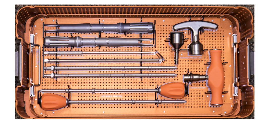
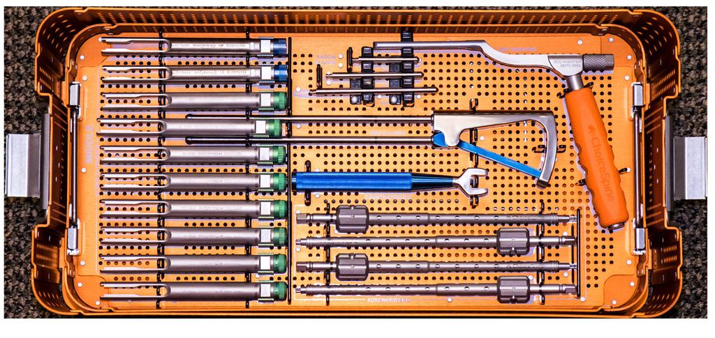
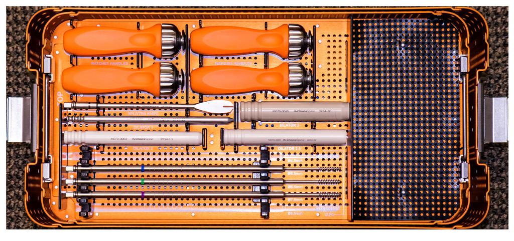
18 Thunderbolttm Instrument Tray Bottom 15 Middle Top
19 Description: The Thunderbolt Minimally Invasive Pedicle Screw System includes implant components made of implant grade titanium alloy (Ti-6Al-4V ELI; ASTM F136) and cobalt chrome alloy (Co-28Cr-6Mo; ASTM F1537). The system also includes instruments made of PEEK (ASTM F2826), Tantalum (ASTM F560), stainless steel (ASTM F899/A564) and aluminum (ASTM B221). These components are available in various designs and sizes that allow the surgeon to build an implant construct suited to a patient s anatomical and physiological requirements. The components include: polyaxial pedicle screws, set screws, rods, instruments and sterilizer trays. Indications: The Thunderbolt Minimally Invasive Pedicle Screw System is intended to provide immobilization and stabilization of spinal segments in skeletally mature patients as an adjunct to fusion in the treatment of the following acute and chronic instabilities or deformities of the thoracic, lumbar, and sacral spine: degenerative disc disease (DDD; defined as back pain of discogenic origin with degeneration of the disc confirmed by history and radiographic studies); spondylolisthesis; trauma (i.e., fracture or dislocation); spinal stenosis; deformities or curvatures (i.e., scoliosis, kyphosis, and/or lordosis); tumor; pseudoarthrosis; and failed previous fusion. When used in a posterior percutaneous approach with MIS instrumentation, the Thunderbolt System is intended for noncervical pedicle fixation for the following indications: degenerative disc disease (defined as back pain of discogenic origin with degeneration of the disc confirmed by history and radiographic studies); spondylolisthesis; trauma (i.e., fracture or dislocation); spinal stenosis; curvatures (i.e., scoliosis, kyphosis, and/or lordosis); tumor, pseudoarthrosis; and failed previous fusion in skeletally mature patients. Contraindications: Contraindications include, but are not limited to: -infection, systemic or localized -signs of local inflammation -morbid obesity -fever or leukocytosis -mental illness -alcoholism or drug abuse -pregnancy -severe osteopenia -suspected or documented sensitivity or allergies to the implant materials -presence of congenital abnormalities, vague spinal anatomy, tumors, or any other condition which prevents secure implant screw fixation and/or decreases the useful life of the device -any condition having inadequate tissue coverage over the operative site -any circumstances not described under Indications for Use -patients unwilling or unable to follow post-operative instructions Cautions, Precautions, Warnings, Possible Adverse Effects CAUTIONS: Mixing of dissimilar metals can accelerate the corrosion Process. Stainless steel and titanium components must NOT be used together. Do not use components of the Thunderbolt and Lancer Pedicle Screw Systems with components from any other manufacturer. As with all orthopedic implants, none of the Thunderbolt and Lancer Pedicle Screw Systems components should ever be reused under any circumstances. Precautions: The implantation of pedicle screw spinal systems should be performed only by experienced spinal surgeons with specific training in the use of this pedicle screw spinal system because this is a technically demanding procedure presenting a risk of serious injury to the patient. Patients who smoke have been shown to have an increased incidence of non-union. These patients should be advised of this fact and warned of the consequences. Other poor candidates for spine fusion include obese, malnourished, those with poor muscle and bone quality, and nerve paralysis patients. Warnings: The safety and effectiveness of pedicle screw spinal systems have been established only for spinal conditions with significant mechanical instability or deformity requiring fusion with instrumentation. These conditions are significant mechanical instability or deformity of the thoracic, lumbar, and sacral spine secondary to severe spondylolisthesis (grade 3 and 4) of the L5-S1 vertebrae, degenerative spondylolisthesis with objective evidence of neurologic impairment, fracture, dislocation, scoliosis, kyphosis, spinal tumor, and failed previous fusion (pseudarthrosis). The safety and effectiveness of these devices for any other conditions are unknown. This device system is not intended to be the sole means of spinal support. It s use without a bone graft or in cases that develop into a non-union will not be successful. No spinal implant can withstand the loads of the body without maturation of a solid fusion mass, and in this case, bending, loosening or fracture of the implant will eventually occur. The proper selection and compliance of the patient will greatly affect the results. The implantation of spinal systems should be performed only by spinal surgeons fully experienced in the surgical techniques required for the use of such implants. Even with the use of spinal implants, a successful result in terms of pain, function, or fusion is not always achieved in every surgical case. The Thunderbolt Minimally Invasive Pedicle Screw System has not been evaluated for safety and compatibility in the MR environment. The Thunderbolt Minimally Invasive Pedicle Screw System has not been tested for heating or migration in the MR environment. Propelling Spinal Surgery 16


20 LIT # Thunderbolt STG REV 02 08/ ERIN DRIVE KNOXVILLE, TN office fax
Table of Contents.
 surgical technique The Ambassador TM Anterior Cervical Plate System is a versatile system of implants and instruments with a variety of sizes to provide optimal anatomic compatibility. The integrated cam
HawkeyeTM Peek. surgical technique
 HawkeyeTM Peek surgical technique Introduction The ChoiceSpine HAWKEYE Vertebral Body Replacement (VBR) System is intended for use in the thoracolumbar spine (T1 - L5) to replace a collapsed, damaged,
A U X I L I A R Y C O N N E C T O R S Surgical Technique
 A U X I L I A R Y C O N N E C T O R S Surgical Technique AUXILIARY CONNECTORS ISSYS LP Auxiliary Connectors The ISSYS LP auxiliary connectors were designed to provide medial-lateral variability for the
Threshold Pedicular Fixation System Surgical Technique
 Threshold Pedicular Fixation System Surgical Technique Table of Contents Patient Preparation and Positioning... 2 Determining Incision Location... 3 Assembling the Cannulated Awl... 4 Guide Wire Placement...
Y o u r Id e a s En g i n e e r e d t o Li f e
 ISSYS LP Spinal Fixation System Surgical Guide Y o u r Id e a s En g i n e e r e d t o Li f e In t r o d u c t i o n ISSYS LP Sp i n a l Fixation System The foundation of the ISSYS LP Spinal Fixation System
TiLock XT Minimally Invasive Surgery (MIS) Pedicle Screw System
 Pedicle Screw System") TiLock XT Minimally Invasive Surgery (MIS) Pedicle Screw System The Genesys Spine TiLock XT Minimally Invasive Surgery (MIS) Pedicle Screw System consists of rods (straight and curved), lock screws, and
TiLock XT Minimally Invasive Surgery (MIS) Pedicle Screw System The Genesys Spine TiLock XT Minimally Invasive Surgery (MIS) Pedicle Screw System consists of rods (straight and curved), lock screws, and
TiLock XT Minimally Invasive Surgery (MIS) Pedicle Screw System
 Pedicle Screw System") Minimally Invasive Surgery (MIS) Pedicle Screw System Surgical Technique Guide 2 Minimally Invasive Surgery (MIS) Pedicle Screw System The Genesys Spine Minimally Invasive Surgery (MIS) Pedicle Screw System
Minimally Invasive Surgery (MIS) Pedicle Screw System Surgical Technique Guide 2 Minimally Invasive Surgery (MIS) Pedicle Screw System The Genesys Spine Minimally Invasive Surgery (MIS) Pedicle Screw System
TM TM Surgical Technique
 TM TM Surgical Technique TABLE OF CONTENTS Reli SP Spinous Plating System Overview Device Description Implant Features Indications Instruments Access Instruments Preparation Instruments Insertion Instruments
nvt Transforaminal Lumbar Interbody Fusion System
 nvt Transforaminal Lumbar Interbody Fusion System 1 IMPORTANT INFORMATION FOR PHYSICIANS, SURGEONS, AND/OR STAFF The nv a, nv p, and nv t are an intervertebral body fusion device used in the lumbar spine
nva Anterior Lumbar Interbody Fusion System
 nva Anterior Lumbar Interbody Fusion System 1 IMPORTANT INFORMATION FOR PHYSICIANS, SURGEONS, AND/OR STAFF The nv a, nv p, and nv t are an intervertebral body fusion device used in the lumbar spine following
nvp Posterior Lumbar Interbody Fusion System
 nvp Posterior Lumbar Interbody Fusion System 1 IMPORTANT INFORMATION FOR PHYSICIANS, SURGEONS, AND/OR STAFF The nv a, nv p, and nv t are an intervertebral body fusion device used in the lumbar spine following
VTI INTERLINK PEDICLE SCREW SYSTEM
 VTI INTERLINK PEDICLE SCREW SYSTEM SURGICAL TECHNIQUE FORWARD THINKING FOR THE BACK. DEVICE DESCRIPTION The VTI InterLink Pedicle Screw System is comprised of polyaxial pedicle screws in various diameters
TiLock 2 Spinal System. Surgical Technique
 TiLock 2 Spinal System Surgical Technique Table of Contents Page Preoperative Planning 4 Pedicle Preparation 5 Probe 5 Tap Pedicle 6 Screw Options 7 Screw Insertion 8 Aligning the Windows 9 Rod Insertion
Valencia Pedicle Screw Surgical Technique
 Valencia Pedicle Screw Surgical Technique VALENCIA CIRCUIT TABLE OF CONTENTS Design Rationale Indications for Use Surgical Technique 1. Pedicle Preparation 2. Screw Insertion 3. Rod Placement 4. Locking
Royal Oak Cervical Plate System
 Royal Oak Cervical Plate System Manufactured by Nexxt Spine, Inc. Royal Oak Cervical Plate System INTRODUCTION FEATURES AND BENEFITS Table of Contents SURGICAL TECHNIQUE Step 1. Patient Positioning Step
 Visit our website on www.biotech-medical.com The DLP - Dorso-Lumbar Polyaxial Screw System has been designed to address the pathologies of the thoracolumbar spine. The DLP System contains a wide range
HydraLok. Operative Technique. Polyaxial Pedicle Screw System
 HydraLok Operative Technique Polyaxial Pedicle Screw System Table of Contents Introduction...1 OPERATIVE TECHNIQUE OVERVIEW...2 DETAILED OPERATIVE TECHNIQUE...4 LOCATE AND PREPARE THE PEDICLE...4 PROBE
Alamo T Transforaminal Lumbar Interbody System Surgical Technique
 Transforaminal Lumbar Interbody System Surgical Technique Table of Contents Indications and Device Description.............. 1 Alamo T Implant Features and Instruments...........2 Surgical Technique......................
SURGICAL TECHNIQUE. SECURIS Pedicle Screw System for Minimally Invasive Surgery. 2 I SECURIS Pedicle Screw System
 Surgical Technique e Guide SECURIS Pedicle Screw System for Minimally Invasive Surgery Securis Pedicle Screw System has been engineered to provide temporary posterior stabilization of the thoracolumbar
Cervical Spacer System surgical technique
 Blackhawk TM Cervical Spacer System surgical technique Blackhawk TM The BLACKHAWK Cervical Spacer System is designed to provide biomechanical stabilization as an adjunct to fusion. Spinal fixation should
SURGICAL TECHNIQUE GUIDE TRESTLE. Anterior Cervical Plating System
 SURGICAL TECHNIQUE GUIDE TRESTLE Anterior Cervical Plating System 2 SURGICAL TECHNIQUE GUIDE SURGICAL TECHNIQUE GUIDE System Features Large window enables visualization of graft site and end plates Screw
X-spine Surgical Technique
 X-spine Surgical Technique The X90 Pedicle Screw System Revolutionary Design and Function This document is intended exclusively for experts in the field, particularly physicians, and is not intended for
EXCELLA ll. Spinal System
 EXCELLA ll Spinal System Excella II Spinal System INDICATIONS FOR USE The Innovasis Excella II Spinal System is intended for use in the non-cervical area of the spine. WARNING: The safety and effectiveness
ACP. Anterior Cervical Plate System SURGICAL TECHNIQUE
 ACP Anterior Cervical Plate System SURGICAL TECHNIQUE ACP TABLE OF CONTENTS INTRODUCTION 4 INDICATIONS AND CONTRAINDICATIONS 5 WARNINGS AND PRECAUTIONS 6 IMPLANT DESCRIPTION 7 INSTRUMENTS 10 SURGICAL
Zimmer Anterior Buttress Plate System. Surgical Technique
 Zimmer Anterior Buttress Plate System Surgical Technique 2 Zimmer Anterior Buttress Plate System Surgical Technique Zimmer Anterior Buttress Plate System Surgical Technique Description, Indications & Contraindications...
Alamo C. Cervical Interbody System Surgical Technique. An Alliance Partners Company
 Cervical Interbody System Surgical Technique Table of Contents Indications for Use................................1 Device Description............................... 1 Alamo C Instruments..............................
ACP1 CERVICAL PLATE SPINAL SYSTEM SURGICAL TECHNIQUE GUIDE II.
 I. ACP1 CERVICAL PLATE II. SPINAL SYSTEM SURGICAL TECHNIQUE GUIDE I. Introduction The Gold Standard Orthopaedics, LLC ACP1 Spinal System was designed with surgeons to incorporate strength, functionality,
Surgical Technique 1
 1 Surgical Technique TELLURIDE 2 MIS SPINAL FIXATION SYSTEM The Telluride 2 MIS Spinal Fixation System is a simple, robust and versatile minimally invasive pedicle screw system consisting of implants and
Ballista Percutaneous Screw Placement System. Surgical Technique
 Ballista Percutaneous Screw Placement System Surgical Technique Contents Introduction... Page 1 Features And Benefits... Page 2 Implants... Page 3 Instruments... Page 4 Surgical Technique... Page 8 Indications
Ballista Percutaneous Screw Placement System
 Surgical Technique Ballista Percutaneous Screw Placement System A Minimally Invasive Approach for Posterior Spinal Surgery True percutaneous system Helical Flange locking mechanism Contents Introduction...
O PE RATIV E TE C HN IQ U E. Minimally Invasive Posterior Fixation
 O PE RATIV E TE C HN IQ U E TM Minimally Invasive Posterior Fixation Table of Contents 1 PRE-OPERATIVE PLANNING Patient Positioning Pedicle Identification and Incision Planning 4 OPERATIVE TECHNIQUE Incision
EXCELLA MIS. Spinal System
 EXCELLA MIS Spinal System Excella MIS Spinal System INDICATIONS FOR USE The Innovasis Excella MIS Spinal System is intended for use in the non-cervical area of the spine. WARNING: The safety and effectiveness
USS Variable Axis Screw (VAS) System. For posterior fixation of the lumbar spine.
 System. For posterior fixation of the lumbar spine.") USS Variable Axis Screw (VAS) System. For posterior fixation of the lumbar spine. Technique Guide Instruments and implants approved by the AO Foundation Table of Contents Introduction USS Variable Axis
USS Variable Axis Screw (VAS) System. For posterior fixation of the lumbar spine. Technique Guide Instruments and implants approved by the AO Foundation Table of Contents Introduction USS Variable Axis
Hinged Laminoplasty System surgical technique
 BlackbirdTM Hls Hinged Laminoplasty System surgical technique Blackbird TM Hls The ChoiceSpine Blackbird Hinged Laminoplasty System (HLS) design eliminates fitting plates through trial and error bending.
OPERATIVE TECHNIQUE. anterior cervical plating system
 OPERATIVE TECHNIQUE 3º anterior cervical plating system Introduction 1 Pre-Operative Technique 2 Oerative Technique 3 Instructions for Use 12 Part Numbers 16 The surgical technique shown is for illustrative
Zimmer Facet Screw System Surgical Technique
 Zimmer Facet Screw System Surgical Technique 2 Zimmer Facet Screw System Surgical Technique Zimmer Facet Screw System Surgical Technique Description, Indications & Contraindications...3 Surgical Technique...4
A Fusion of Versatility, Performance and Ease.
 MATRIX Spine System. Degenerative and Deformity. System Guide A Fusion of Versatility, Performance and Ease. Instruments and implants approved by the AO Foundation The MATRIX Spine System is a universal
INTELLIGENT SPINAL SYSTEM
 INTELLIGENT SPINAL SYSTEM I. Introduction II. Product Specification III. Surgical Technique IV. Ordering Information V. IFU for Lospa IS SPINAL SYSTEM The LOSPA IS spinal system consists of
BAK/C Cervical Anterior Interbody Fusion System
 Surgical Technique BAK/C Cervical Anterior Interbody Fusion System The Comfortable Choice for Cervical Fusion BAK/C Cervical Surgical Technique 1 The BAK/C Cervical Fusion System is an alternative to conventional
Imola Lateral IBF System Surgical Technique
 Imola Lateral IBF System Surgical Technique IMOLA CIRCUIT TABLE OF CONTENTS Design Rationale Instructions for Use Surgical Technique 1. Table Mounting 2. Surgical Planning & Targeting 3. Access and Preparation
Thoracolumbar Solutions. Cypher. MIS Screw System. Surgical Technique Guide
 Thoracolumbar Solutions Cypher MIS Screw System Surgical Technique Guide 2 Cypher MIS Screw System Surgical Technique Guide Game Changing Technology 3 mm of medial-lateral translation encourages optimal
EXACTECH SPINE. Operative Technique. Cervical Spacer System. Surgeon focused. Patient driven. TM
 EXACTECH SPINE Operative Technique Cervical Spacer System Surgeon focused. Patient driven. TM ACAPELLA ONE Acapella One Cervical Spacer System is an anterior cervical discectomy and fusion device with
Technique Guide MAXIMUM ACCESS SURGICAL PLATFORM
 Technique Guide MAXIMUM ACCESS SURGICAL PLATFORM MAXIMUM ACCESS SURGICAL PLATFORM CONTENTS Preface 1 SpheRx II Anterior Technique Guide 2 Equipment Requirements 2 Patient Positioning and O.R. Setup 2 Staple
MEDACTA UNCONSTRAINED SCREW TECHNOLOGY - REDUCTION SCREWS. Surgical Technique. Hip Knee Spine Navigation
 .U.S.T. MEDACTA UNCONSTRAINED SCREW TECHNOLOGY - REDUCTION SCREWS Hip Knee Spine Navigation M.U.S.T. Hip Knee Spine Navigation INTRODUCTION The Medacta Unconstrained Screw Technology [M.U.S.T.] Pedicle
Surgical Technique Manual
 Surgical Technique Manual Surgeon Designers Richard G. Fessler, MD, PhD Northwestern University, Chicago, IL Robert A. Hart, MD Oregon Health and Science University, Portland, OR Robert Labrom, MD Queensland
Thoracolumbar Spine Locking Plate (TSLP) System. A low-profile plating system for anterior stabilization of the thoracic and lumbar spine.
 System. A low-profile plating system for anterior stabilization of the thoracic and lumbar spine.") Thoracolumbar Spine Locking Plate (TSLP) System. A low-profile plating system for anterior stabilization of the thoracic and lumbar spine. Technique Guide Instruments and implants approved by the AO Foundation
Thoracolumbar Spine Locking Plate (TSLP) System. A low-profile plating system for anterior stabilization of the thoracic and lumbar spine. Technique Guide Instruments and implants approved by the AO Foundation
Veyron -C Anterior Cervical System Surgical Technique
 Veyron -C Anterior Cervical System Surgical Technique 2 Veyron-C Anterior Cervical System Surgical Technique Veyron-C Anterior Cervical System Surgical Technique Description, Indications & Contraindications...3
100 Interpace Parkway Parsippany, NJ
 100 Interpace Parkway Parsippany, NJ 07054 www.biometspine.com 800-526-2579 All trademarks are the property of Biomet, Inc. or one of its subsidiaries, unless otherwise indicated. Rx Only. 2009 EBI, LLC.
ASFORA ANTERIOR CERVICAL PLATE SYSTEM (AACP) SURGICAL PROCEDURE MANUAL
 SURGICAL PROCEDURE MANUAL") ASFORA ANTERIOR CERVICAL PLATE SYSTEM (AACP) SURGICAL PROCEDURE MANUAL Contents: Introduction Indications Contraindications Warnings Precautions Implant Overview Instruments Overview Surgical Technique
ASFORA ANTERIOR CERVICAL PLATE SYSTEM (AACP) SURGICAL PROCEDURE MANUAL Contents: Introduction Indications Contraindications Warnings Precautions Implant Overview Instruments Overview Surgical Technique
LCP Medial Distal Tibia Plate, without Tab. The Low Profile Anatomic Fixation System with Angular Stability and Optimal Screw Orientation.
 LCP Medial Distal Tibia Plate, without Tab. The Low Profile Anatomic Fixation System with Angular Stability and Optimal Screw Orientation. Technique Guide LCP Small Fragment System Table of Contents Introduction
4.5 System. Surgical Technique. This publication is not intended for distribution in the USA.
 4.5 System Surgical Technique This publication is not intended for distribution in the USA. Contents EXPEDIUM 4.5 Spine System 2 Features and Benefits 3 Surgical Technique Extended Tandem Connector 4 Placement
TABLE OF CONTENTS. Vault C Anterior Cervical Discectomy 2 and Fusion (ACDF) System Overview. Implants 3. Instruments 5. Surgical Technique 10
 System Overview. Implants 3. Instruments 5. Surgical Technique 10") Surgical Technique TABLE OF CONTENTS Vault C Anterior Cervical Discectomy 2 and Fusion (ACDF) System Overview Indications 2 Implants 3 Instruments 5 Surgical Technique 10 1. Preoperative planning 10 2.
Surgical Technique TABLE OF CONTENTS Vault C Anterior Cervical Discectomy 2 and Fusion (ACDF) System Overview Indications 2 Implants 3 Instruments 5 Surgical Technique 10 1. Preoperative planning 10 2.
Technique Guide. 3.5 mm LCP Low Bend Medial Distal Tibia Plate Aiming Instruments. Part of the 3.5 mm LCP Percutaneous Instrument System.
 Technique Guide 3.5 mm LCP Low Bend Medial Distal Tibia Plate Aiming Instruments. Part of the 3.5 mm LCP Percutaneous Instrument System. Table of Contents Introduction 3.5 mm LCP Low Bend Medial Distal
AccuVision Minimally Invasive Spinal Exposure System
 Surgical Technique AccuVision Minimally Invasive Spinal Exposure System Working Beyond the Tube Lighted blades for superior viewing Maximum stabilization Contents Introduction... Page 1 Features and Benefits...
VECTRA-T SURGICAL TECHNIQUE. The Translational Anterior Cervical Palate System. This publication is not intended for distribution in the USA.
 VECTRA-T The Translational Anterior Cervical Palate System This publication is not intended for distribution in the USA. SURGICAL TECHNIQUE Image intensifier control This description alone does not provide
SURGICAL TECHNIQUE GUIDE SOLANAS. Posterior Cervico-Thoracic Fixation System Adjustable Bridge System
 SURGICAL TECHNIQUE GUIDE SOLANAS Posterior Cervico-Thoracic Fixation System Adjustable Bridge System 2 SURGICAL TECHNIQUE GUIDE Preface SOLANAS Posterior Cervico-Thoracic Fixation System is designed to
Surgical Technique. Apache Anterior Lumbar Interbody Fusion
 Surgical Technique Apache Anterior Lumbar Interbody Fusion 2 Table of Contents Page Preoperative Planning 4 Patient Positioning 4 Disc and Endplate Preparation 4 Distraction/Size Selection 5 Implantation
Dymaxeon Spine System. Simple, Streamlined, Smart. Surgical Procedure
 Simple, Streamlined, Smart Surgical Procedure Introduction The Dymaxeon pedicle screw system offers the spinal surgeon an outstanding system for stabilization of spinal deformity, reduction of spondylolisthesis,
TABLE OF CONTENTS. ShurFit Anterior Cervical Interbody Fusion (ACIF) System Overview 2. Implant Specifications 3. Instrument Features 4
 System Overview 2. Implant Specifications 3. Instrument Features 4") Surgical Technique TABLE OF CONTENTS ShurFit Anterior Cervical Interbody Fusion (ACIF) System Overview 2 Product Highlights 2 Indications 2 Implant Specifications 3 Instrument Features 4 Surgical Technique
Surgical Technique TABLE OF CONTENTS ShurFit Anterior Cervical Interbody Fusion (ACIF) System Overview 2 Product Highlights 2 Indications 2 Implant Specifications 3 Instrument Features 4 Surgical Technique
The Most Reliable Spinal Solution
 MFG : 09.02.20 REV : 1 4CIS VANE introduces you the reliable pedicle screw The Most Reliable Spinal Solution Non-slip threaded joint Ergonomic design Wedged trapezoid thread Superior locking mechanism
Surgical Technique Guide
 Sacroiliac Joint Fusion System Surgical Technique Guide Moving Life Forward Table of Contents SiCure Implant Overview...2 SiCure System Information...3 X-ray Basics...4 Patient Positioning....5 Surgical
Ref: Q400-09T1 EBI Spine. September 05/VS02. c/o BIOMET Spain Orthopaedics, S.L.
 Ref: Q400-09T1 EBI Spine. September 05/VS02 c/o BIOMET Spain Orthopaedics, S.L. www.ebimedical.com EBI Omega 21 TM LP Since its introduction in 1996, and with thousands of patients treated so far, the
Thoracolumbar Solutions. Vital Spinal Fixation System. Degenerative. Surgical Technique Guide
 Thoracolumbar Solutions Vital Spinal Fixation System Degenerative Surgical Technique Guide 2 Vital Spinal Fixation System Surgical Technique Guide Vital Spinal Fixation System is an optimized instrument
OPERATIVE TECHNIQUE. CONSTRUX Mini PTC. Mini PTC Spacer System
 OPERATIVE TECHNIQUE CONSTRUX Mini PTC Mini PTC Spacer System TABLE OF CONTENTS Introduction 1 Operative Technique 2 Part Numbers 6 Indications For Use 7 INTRODUCTION 1 INTRODUCTION The CONSTRUX Mini PTC
InFix. Anterior Lumbar Device. Surgical Technique Guide
 InFix Anterior Lumbar Device Surgical Technique Guide 2 InFix Anterior Lumbar Device Surgical Technique Guide InFix Anterior Lumbar System s modular design is intended to restore lordosis, disc height
operative technique Universal Application
 operative technique Universal Application Introduction Introduction Building upon the design rationale of the Xia Spinal System, the new Xia Spinal System represents the latest advancement in spinal implant
I. II. SPINAL SYSTEM SURGICAL TECHNIQUE GUIDE
 I. GS1 II. SPINAL SYSTEM SURGICAL TECHNIQUE GUIDE Introduction The Gold Standard Orthopaedics, LLC GS1 Spinal System designed in conjunction with Richard Holt, M.D. incorporates both strength and function
VIPER PRIME TM System. Surgical Technique
 VIPER PRIME TM System Surgical Technique Contents Product Overview Introduction 2 Features and Benefits 3 One Tool Screw Insertion 5 Surgical Technique OR Set Up 6 Assembly of the VIPER PRIME TM Inserter
VIPER PRIME TM System. Surgical Technique
 VIPER PRIME TM System Surgical Technique Contents Product Overview Introduction 2 Features and Benefits 3 One Tool Screw Insertion 5 Surgical Technique OR Set Up 6 Assembly of the VIPER PRIME TM Inserter
Cervical Screw System
 Cervical Screw System LnK Posterior Cervical Screw The LnK Cervical Fixation System provides a top-loading, simple and secure system for rigid fixation. The LnK Cervical Fixation system includes instrumentation
Apache Cervical Interbody Fusion Device. Surgical Technique. Page of 13. LC-005 Rev F
 LC-005 Rev F Apache Cervical Interbody Fusion Device Page of 13 Surgical Technique INDICATIONS: When used as an intervertebral body fusion device, the Genesys Spine Interbody Fusion System is indicated
Technique Guide. MATRIX Spine System MIS Instrumentation. The total solution for simple and complex spine pathology.
 Technique Guide MATRIX Spine System MIS Instrumentation. The total solution for simple and complex spine pathology. Table of Contents Introduction MATRIX Spine System MIS Instrumentation 2 AO Principles
M.I.S. MAKE IT SMART IN ONE SYSTEM. Surgical Technique. Hip Knee Spine Navigation
 M.I.S. MAKE IT SMART IN ONE SYSTEM Surgical Technique Hip Knee Spine Navigation M.U.S.T. Mini Open Surgical Technique Hip Knee Spine Navigation 2 C O N T E N T S 1 INTRODUCTION 4 2 SURGICAL TECHNIQUE 5
EXPEDIUM 5.5 Spine System Family Product Catalogue
 EXPEDIUM 5.5 Spine System Family Product Catalogue Including: EXPEDIUM EXPEDIUM Vertebral Body Derotation Universal Connector Set Cobalt Chromium Rods INTRODUCTION Contents EXPEDIUM Spine System is a comprehensive
product overview Implant heights range from 8mm-20mm in 2mm increments, with two lordocic angle options of 6 and 12.
 ETHOS A-Spacer PEEK System Surgical Technique Guide Synchronizing Medical Innovation with Global Markets product overview The SyncMedical Ethos PEEK IBF System is an intervertebral body fusion device for
Trinica and Trinica Select Anterior Cervical Plate System
 Surgical Technique Trinica and Trinica Select Anterior Cervical Plate System A New Twist to Anterior Cervical Plates Trinica and Trinica Select Surgical Technique 1 Trinica and Trinica Select Anterior
Surgical Technique FOR U.S. DOMESTIC USE ONLY
 Surgical Technique FOR U.S. DOMESTIC USE ONLY Polyaxial Screws HA Coated Polyaxial Screws Uniplanar Screws Reduction Screws Reduction Uniplanar Screws Modular Screws TABLE OF CONTENTS Reform Pedicle Screw
MATRIX Spine System Degenerative. A posterior pedicle screw and rod fixation system.
 MATRIX Spine System Degenerative. A posterior pedicle screw and rod fixation system. Technique Guide Instruments and implants approved by the AO Foundation Table of Contents Introduction MATRIX Spine
Royal Oak IBFD System Surgical Technique Posterior Lumbar Interbody Fusion (PLIF)
") Royal Oak IBFD System Surgical Technique Posterior Lumbar Interbody Fusion (PLIF) Preoperative Planning Preoperative planning is necessary for the correct selection of lumbar interbody fusion devices.
Royal Oak IBFD System Surgical Technique Posterior Lumbar Interbody Fusion (PLIF) Preoperative Planning Preoperative planning is necessary for the correct selection of lumbar interbody fusion devices.
Introduction. Our hope is that this Surgical Technique Guide enhances your knowledge and contributes to clinical success for your patients.
 Surgical Technique Introduction DePuy Spine continues to support the goal of expanding the spine surgeon s options for the treatment of spinal disorders. Collaborating with renowned spine specialists,
SMV Scientific Bone Plate and Screw System Surgical Technique
 SMV Scientific Bone Plate and Screw System Surgical Technique Description: The SMV Scientific Bone Plate and Screw System consists of non-locking plates and bone screw fasteners in a variety of lengths,
Surgical Technique. Guide
 Surgical Technique Guide DESIGNING SURGEONS Darrel Brodke, M.D. University of Utah Medical Center Dept. of Orthopedic Surgery Salt Lake City, Utah Iain Kalfas, M.D., F.A.C.S The Cleveland Clinic Foundation
Surgical Technique. CONQUEST FN Femoral Neck Fracture System
 Surgical Technique CONQUEST FN Femoral Neck Fracture System Table of Contents Introduction... 3 Indications... 3 Product Overview... 4 Surgical Technique... 5 Patient Positioning... 5 Reduce the Fracture...
Zimmer Trabecular Metal Ankle Interpositional Spacer and Trabecular Metal Ankle Fusion Spacer
 Zimmer Trabecular Metal Ankle Interpositional Spacer and Trabecular Metal Ankle Fusion Spacer Surgical Technique 2 Zimmer Trabecular Metal Ankle Interpositional Spacer and Trabecular Metal Ankle Fusion
Surgical Technique & Product Catalogue. Guide for Open & MIS Procedures
 Surgical Technique & Product Catalogue Guide for Open & MIS Procedures INTRODUCTION The VIPER Cortical Fix Fenestrated Screw System is the first pedicle screw implant to offer enhanced fixation in both
Surgical Technique. Guide and Ordering Information. Favored Angle Screw
 Surgical Technique Guide and Ordering Information Favored Angle Screw C O N T E N T S SURGICAL TECHNIQUE Introduction 1 Screwdriver Application and Screw Placement 2 Segmental Translation 3-7 Segmental
Technique Guide. 3.5 mm LCP Low Bend Medial Distal Tibia Plates. Part of the Synthes locking compression plate (LCP) system.
 system.") Technique Guide 3.5 mm LCP Low Bend Medial Distal Tibia Plates. Part of the Synthes locking compression plate (LCP) system. Table of Contents Introduction 3.5 mm LCP Low Bend Medial Distal Tibia Plates
Technique Guide 3.5 mm LCP Low Bend Medial Distal Tibia Plates. Part of the Synthes locking compression plate (LCP) system. Table of Contents Introduction 3.5 mm LCP Low Bend Medial Distal Tibia Plates
2. Active systemic infection or infection localized to the site of the proposed implantation is contraindications to implantation.
 OIC Pedicle Screw System! The Orthopaedic Implant Company 316 California Ave #701 Reno, NV 89509 USA System Contents: Non-Sterile Implants Single Use Only Non-Sterile Instruments - Reusable 2 Caution:
SerratoTM. Surgical technique
 TM Surgical technique Table of contents Key design features.... 3 System overview.... 4 Surgical technique Patient positioning... 7 Preparing the pedicle.... 8 Screw insertion... 11 Rod contouring... 12
Surgical Technique. Available In Titanium And Stainless Steel
 Surgical Technique Available In Titanium And Stainless Steel Contents Introduction... Page 1 System Design Features... Page 2 Implants... Page 3 Standard Instruments... Page 7 Degenerative Surgical Technique...
ONE SYSTEM, MULTIPLE OPTIONS. Surgical Technique. Hip Knee Spine Navigation
 ONE SYSTEM, MULTIPLE OPTIONS Surgical Technique Hip Knee Spine Navigation MUST MINI Surgical Technique Hip Knee Spine Navigation INTRODUCTION The M.U.S.T. Mini posterior cervical screw system is a modular
LBL-014. Rev
 Package Insert Z- CLAMP ISP System Device Description: The Z-CLAMP ISP System is supplemental fixation device consisting of a variety of shapes and sizes of one-level lumbar and sacral plates and screws.
Posterior Lumbar Interbody Fusion System
 Px Posterior Lumbar Interbody Fusion System Px PEEK INTERBODY FUSION SYSTEM INDICATIONS FOR USE The Innovasis Px PEEK IBF System is an intervertebral body fusion device for use in patients with degenerative
Minimally Invasive Spinal System AVATAR SURGICAL TECHNIQUE GUIDE. Designs For Life. Designs For Life.
 Designs For Life. Minimally Invasive Spinal System SURGICAL TECHNIQUE GUIDE Designs For Life. Minimally Invasive Spinal System CONTENTS Introduction 1 1 Implants 3 Instruments 4 Surgical Technique 7 Product
Dynesys Top-Loading System
 Surgical Technique Dynesys Top-Loading System The Dynamic Stabilization System 2 Dynesys Top-Loading System Surgical Technique Dynesys Top-Loading Spinal System Surgical Technique Dynesys TL Instruments...3
TECHNICAL BROCHURE. Capture Facet Fixation System
 TECHNICAL BROCHURE Capture Facet Fixation System Table of Contents Product Overview...2 Instruments...4 Capture Facet Screw Surgical Technique Patient Preparation and Positioning...6 Guide Pin Placement...7
PILLAR AL. Anterior Lumbar Interbody Fusion (ALIF) and Partial Vertebral Body Replacement (pvbr) PEEK Spacer System OPERATIVE TECHNIQUE
 and Partial Vertebral Body Replacement (pvbr) PEEK Spacer System OPERATIVE TECHNIQUE") PILLAR AL PEEK Spacer System Anterior Lumbar Interbody Fusion (ALIF) and Partial Vertebral Body Replacement (pvbr) OPERATIVE TECHNIQUE Table of Contents 1 INTRODUCTION 2 PRE-OPERATIVE TECHNIQUE 3 OPERATIVE
PILLAR AL PEEK Spacer System Anterior Lumbar Interbody Fusion (ALIF) and Partial Vertebral Body Replacement (pvbr) OPERATIVE TECHNIQUE Table of Contents 1 INTRODUCTION 2 PRE-OPERATIVE TECHNIQUE 3 OPERATIVE
Advantage ALIF. Keith Shevlin Managing Director
 Advantage ALIF Unit 10, 9-11 Myrtle Street, Crows Nest NSW 2065 Keith Shevlin Managing Director keithshevlin@precisionsurgical.com.au Advantage ALIF Introduction & Indications for Use 1 Surgical Technique