SIGMA Revision and M.B.T. Revision Tray. Surgical Technique
|
|
|
- Katrina Ford
- 6 years ago
- Views:
Transcription


1 SIGMA Revision and M.B.T. Revision Tray Surgical Technique
2
3 Contents The SIGMA Revision System Overview 1 SIGMA Revision / M.B.T. Revision Knee System and Revision Knee Surgery Introduction 2 Pre-operative Planning 2 Surgical Technique 3 Intraoperative Evaluation 5 Tibial Preparation 7 Preparation of the Metaphyseal Bone - Tapered Reamer 9 Proximal Tibial Resection - Tapered Reamer 10 Preparation of the Metaphyseal Bone - Broach 12 Preparation of the Femoral Diaphysis 14 Reaming the Medullary Canal 15 Preparation of the Metaphysis (Sleeve Use) 18 Distal Resection 22 Assembling the Prosthesis 37 Trial Reduction 40 Implant Assembly - Sleeve and Stem Use 41 Preparation of the Patella 46 Appendix Appendix 1 - The Cemented Tibial Stem Extensions 49 Appendix 2 - Step Wedge Preparation 52 Appendix 3 - Thick Tray Preparation 55 Appendix 4 - Femoral Assembly - Stem Only Use 56 Appendix 5 - Femoral Assembly - Sleeve Only Use 60 Appendix 6A - Femoral Revision and M.B.T. Revision Tray Compatibility 64 Appendix 6B - SIGMA Revision Anteroposterior Chart (Sleeve Use) 65 Instrument Glossary 66 Anterior/Posterior Resection 24 Notch and Chamfer Resection 28 The Trial Femoral Component 32 Trial Assembly - Sleeve and Stem Use 33 Final Preparation of the Tiba 36
4 The SIGMA Revision System Overview The M.B.T. Revision Knee System is Comprised of the Following Components: Tibial Components are available in eight sizes The SIGMA Revision Knee System is Comprised of the Following Components: Stabilised Femoral Component is available in seven sizes Tibial Metaphyseal Sleeves are available in 29 mm, 37 mm, 45 mm, 53 mm and 61 mm sizes (M/L dimension) Tibial Wedge Augmentation Components: Step Wedge in 5, 10 and 15 mm thicknesses 75, 115 and 150 mm Fluted Universal Stem lengths in 10 to 24 mm diameters in 2 mm increments 30 and 60 mm Cemented Universal Stem lengths in 13 mm diameters. 90, 120, 150 Cemented Tapered Universal stem lengths in 13 mm diameters Thick Trays are available in three different sizes (2, 3 and 4) and two different thicknesses (+15 mm and +25 mm) TC3 Femoral Component is available in seven sizes Modular Femoral Stem, known as the SIGMA Femoral Adapter, which allows the use of the Femoral Metaphyseal Sleeves and Universal Stems. Available in 5 and 7 degree valgus angles Femoral Metaphyseal Sleeves are available in 20 mm, 31 mm, 34 mm, 40 mm and 46 mm sizes (M/L dimension), and can be used with or without a stem 4 mm, 8 mm, 12 mm and 16 mm Distal Femoral Augmentations 4 mm and 8 mm Posterior Femoral Augmentations M.B.T. Tray accepts Rotating Platform inserts from LCS COMPLETE, SIGMA RP, LCS COMPLETE Revision and SIGMA TC3(TM) RP inserts M.B.T. Tray accepts rotating platform hinged inserts from the Orthogenesis LPS (Limb Preservation System), which is compatible with the S-ROM NOILES Rotating Hinge (NRH) femoral component and LPS femoral component Three anteroposterior stem positions: 0, +2 mm and -2 mm 75 mm, 115 mm and 150 mm Fluted Universal Stem Lengths in 10 mm to 24 mm diameters in 2 mm increments 30 mm and 60 mm Cemented Universal Stem Lengths in 13 mm diameter 30 mm and 60 mm Cemented Universal Stem Lengths at 15 mm diameters (Must be used with a sleeve) 90 mm, 120 mm, and 150 mm Tapered Cemented Universal Stem Lengths in 13 mm diameter 90 mm Tapered Cemented Universal Stem Length at 15 mm diameter (Must be used with a sleeve) 1
5 SIGMA Revision/M.B.T. Revision Tray Knee Surgery Introduction In total knee arthroplasty (TKA), failure may result from many causes including: wear, aseptic loosening, infection, osteolysis, ligamentous instability, arthrofibrosis and patellofemoral complications. In approaching revision procedures, the surgeon must address such considerations as the planning of an incision in a previously operated site, the condition of the soft tissue, mobilisation of the extensor mechanism, extraction of the primary prosthesis and the attendant conservation of bone stock. Among the goals of successful revision arthroplasty are the restoration of anatomical alignment and functional stability, fixation of the revision implants and accurate re-establishment of the joint line. Careful selection of the appropriate prosthesis is of paramount importance. Ideally, the revision knee replacement system will offer the options of adjunctive stem fixation and variable stem positions, femoral and tibial augmentation and various levels of prosthetic constraint. Pre-operative Planning Revision total knee arthroplasty begins with thorough clinical and radiographic evaluation. Physical evaluation includes the examination of the soft tissues, taking into account previous skin incisions, range of motion, motor strength, the condition of all neurovascular structures, ligamentous stability and the integrity of the extensor mechanism. Biplanar radiographic views are obtained, as are tangential views of the patella and full-length standing bilateral extremity views for the assessment of alignment and bone stock, documentation of the joint line and evaluation of the present implant fixation. Stress views are helpful in evaluating ligamentous instability. CAT and MRI scans may at times be of value in cases of massive bone loss or substantial anatomic distortion from trauma or metabolic bone disorders. Templates are employed to establish replacement implant size and the alignment of bone cuts, to indicate augmentation of skeletal deficits and to confirm the anatomic joint line. 2
6 Surgical Technique Initial Incision When possible, follow the scar from the primary procedure (Figure 1). Where parallel incisions are present, the more lateral is usually preferred, as the blood supply to the extensor surface is medially dominant. Where a transverse patellectomy scar is present, the incision should transect it at 90 degrees. Where there are multiple incision scars or substantial cutaneous damage (burn cases, skin grafting, etc.), one may wish to consult a plastic surgeon prior to surgery to design the incision, determine the efficacy of preoperative soft tissue expansion and plan for appropriate soft tissue coverage at closure. Figure 1 Capsular Incision The fascial incision extends from the rectus femoris proximal margin to the distal margin of the tibial tubercle following the patella s medial border, maintaining a 3-4 mm cuff for reapproximation of the vastus medialis aponeurosis at closure (Figure 2). Where mobilisation of the extensor mechanism and patella is problematic, extend the skin and capsular incisions proximally. Figure 2 3
7 Surgical Technique Occasionally an early retinacular release is indicated to assist with patellar eversion. Where eversion difficulties persist, a quadriceps snip, a proximal inverted quadriceps incision (modified V-Y) or a tibial-tubercle osteotomy may be indicated. Perform appropriate ligamentous release based upon preoperative and intraoperative evaluation. Release fibrous adhesions to re-establish the suprapatellar pouch and medial and lateral gutters (Figure 3). In many revision cases, the posterior cruciate ligament will be absent or non-functional; when this is the situation, excise any residual portion. Exercise care when everting the patella. Frequently, subluxing the patella laterally is adequate. Doing so will help avoid patellar tendon aversion. Figure 3 Implant Extraction from the Primary Procedure Take care to preserve as much bone as possible. To this end, assemble a selection of tools, including thin osteotomes, an oscillating saw, a Gigli saw, a high-speed burr and various extraction devices. Many cases will require only a thin osteotome. Carefully disrupt the bone/cement or bone/ prosthesis interface before attempting extraction (Figure 4). Disengage the implanted components and extract as gently as possible, in such manner as to avoid fracture and unnecessary sacrifice of bone stock. Where the entire prosthesis is to be replaced, it is advantageous to remove the femoral component first, as this will enhance access to the proximal tibia. Clear all residual bone cement with hand chisels, or power tools. Figure 4 4
8 Intraoperative Evaluation Recommended Surgical Priority 1) Tibial medullary canal preparation 2) Proximal tibial resection 3) Femoral medullary canal preparation 4) Distal femoral resections 5) Establishment of femoral rotation 6) Anteroposterior, notch and chamfer resections 7) Establishment of tibial rotation 8) Tibial deficit augmentation 9) Final tibial preparation 10) Patellar preparation 11) Implantation of the components The surgeon should establish two anatomic conditions to facilitate revision arthroplasty: the level of the joint line and the disparity in the flexion and extension gaps (Figure 5). Figure 5 Joint Line Evaluation In an average knee in full extension, the true joint line can be approximated in reference to several landmarks. It lies mm distal to the femoral PCL attachment. It lies approximately 3 cm distal to the medial epicondyle and 2.5 cm distal to the lateral epicondyle. It lies distal to the inferior pole of the patella (approximately one finger width). Level with the old meniscal scar, if available. Additional preoperative joint line assessment tools include: 1) Review of original preoperative radiograph of the TKA 2) Review of radiograph of contralateral knee if non-implanted 5
9 Intraoperative Evaluation Joint Space Assessment Joint space is evaluated with spacer blocks to determine the flexion/extension gap relationship and the symmetry of both the flexion and extension gaps, and to indicate if prosthetic augmentation is needed to ensure postoperative equivalence (Figure 6). A 1 mm shim should be used for the extension gap and removed when assessing the flexion gap (Figure 7). This will compensate for the 1 mm component difference between the distal and posterior condyles. Size the tibia first and initially choose the same size of femoral component. This can then be adjusted to accommodate the following: Where flexion gap >extension gap: To decrease flexion gap without affecting extension gap, apply a larger femoral component. This is particularly important where an IM stem extension is indicated, as the stem extension will determine the anteroposterior positioning of the component and the consequent flexion gap. Figure 6 Figure 7 Where stem positioning will not permit posterior augmentation, assemble a 2 mm offset stem bolt with the arrow pointing anteriorly to the component, translating the femoral component 2 mm posteriorly. (Refer to page 34 for further explanation.) Where there is insufficient stability, a cemented femoral stem may be substituted, allowing the component to be seated further posteriorly. Where the joint line is elevated, the preferred correction is posterior femoral augmentation. The alternative additional distal femoral resection and use of a thicker tibial insert to tighten the flexion gap is not recommended, as considerable bone stock has been sacrificed in the primary procedure, and it is important that additional resection of the distal femur be avoided. The possible exception is where the joint line is not elevated and minimal distal resection will increase the extension gap toward equivalency with the flexion gap. Where significant flexion laxity persists despite these manoeuvers, consider the use of the TC3 component. Where extension gap >flexion gap: To decrease extension gap without affecting flexion gap, augment the distal femur with bone graft or prosthetic augmentation. It is important to note that this will lower the joint line, which is usually desirable as it is generally found to be elevated in revision cases. This will lessen the incidence of postoperative patella infera. 6
10 Initial Preparation of the Tibia The Tibial Alignment System When preoperative evaluation and X-rays indicate that fluted stem extensions, metaphyseal sleeves or wedges are required, it is recommended that the proximal tibia be prepared with reference to the position of the IM rod. 2-4 cm Where a cemented Universal Stem Extension is indicated, see Appendix I. Place the knee in maximal flexion with the patella laterally retracted and the tibia distracted anteriorly and stabilised. Release fibrosis around the tibial border or excise as required to ensure complete visualisation of its periphery. Figure 8 Approximate the location of the medullary canal with reference to preoperative anterior/posterior (A/P) and lateral X-rays and to the medial third of the tibial tubercle. Introduce a 5 16 in. (9 mm) drill into the canal to a depth of 2 to 4 cm. Avoid cortical contact (Figures 8 and 9). Figure 9 7
11 Initial Preparation of the Tibia Reaming the Medullary Canal Assemble the straight reamer to the T-handle. If power reaming, it will be necessary to attach the modified Hudson adapter to the straight reamer. The shaft of the reamer contains markings in 25.4 mm (1 in.) increments. Each marking is numbered to use as a reference when reaming to the appropriate depth. Universal fluted stem lengths are available in 75, 115 and 150 mm. Determine the length and diameter of the prosthetic stem extension with templates (Cat. No ) applied to preoperative X-rays. T-handle Straight Reamer Utilising the reamer depth scale and the markings on the straight reamer, ream to the predetermined depth so the preselected marking on the reamer is positioned at the desired tibial resection level. Sequentially open the canal with progressively larger reamers until firm endosteal engagement is established (Figure 10). Note: Simple cortical contact should not be construed as engagement. The fixed relationship of the reamer to the cortices ensures the secure fit of the appropriate reamer and, subsequently, the corresponding fluted stem. It is equally important to not over-ream osteopenic bone. While reaming the proximal tibia, pay close attention to the reamer to assure that it is somewhat centrally located to the exposed proximal tibial surface. Eccentric reaming can occur, which could lead to undersizing of the tibial component. The size of the final reamer indicates the diameter of the implant stem. The universal fluted stems are available in even sizes (10 through 24 mm). Perform final reaming with an even-sized reamer. Figure 10 Refer to Appendix 1 for cemented Universal stem preparation. 8
12 Preparation of the Metaphyseal Bone Tapered Reamer For Diaphyseal Engaging Stem and Metaphyseal Filling Sleeve Attach the appropriately sized stem trial to the end of the reamer. Tapered Reamer Note: Assembly of the stem trial may be aided by the pre-attachment of the T-handle. Tibial Resection Plane Taper ream to the planned proximal tibial resection level (Figure 11). Note: Use the cemented taper reamer when requiring a cement mantle or when utilising a sleeve. Use the press-fit tapered reamer when line-to-line fit is desired and a sleeve will not be utilised (Figure 11). Use end-cutting primary reamer (cat. no ) when a stem or sleeve will not be used. Note: To avoid stem trial disengagement, do not reverse ream. At this point, intraoperatively determine if a metaphyseal sleeve will be used. Note: Metaphyseal sleeves are ideal to provide filling of Engh type II or III defects in revision TKA.* The steps also provide progressive loading of the bone with porous coating. Figure 11 If a metaphyseal sleeve is selected, see page 12 for details of how to broach the metaphyseal bone. If a metaphyseal sleeve will not be used, see page 11 to prepare for the proximal tibial resection. * G. A. Engh, Bone defect classification, in Revision Total Knee Arthroplasty, G. A. Engh and C. H. Rorabeck, Eds., pp , Lippincott Williams & Wilkins, Baltimore, Md, USA,
13 Proximal Tibial Resection Tapered Reamer Attach the 2 degree tibial cutting block to the I.M. tibial referencing device. Attach the I.M. tibial referencing device to the shaft of the tapered reamer. Position the I.M. tibial referencing device with the pre-attached 2 degree cutting block onto the shaft and allow it to descend to the proximal tibial surface. Since considerable bone stock may have been sacrificed in the primary total knee arthroplasty, minimise the amount resected: no more than 1-2 mm from the most prominent condyle, managing residual defects of the contralateral condyle with either prosthetic augment or bone graft. Lateral Set Screw Resection is based on tibial deficiency and the level of the joint line. Compensate deficiencies with sleeves, wedges and/or bone grafts. Advance the cutting block to the anterior tibial cortex and lock into position by tightening the knurled knob on the outrigger. Preliminary rotational alignment is based on the medial third of the tibial tubercle. Secure the alignment device to the reamer shaft with the lateral setscrew. (Figure 12) Figure 12 Pin the tibial cutting block so a minimal resection is made from the proximal tibia. Utilise the stylus when necessary. (Figure 12) 10
14 Proximal Tibial Resection Tapered Reamer Note: If a metaphyseal sleeve is to be used, tibial resection using the 2 degree tibial cutting device is unnecessary as the tibial resection will be performed using the tibial sleeve broach. (see page 14, Figure 15) Note: There is a slotted and non-slotted end to the stylus. The difference between the two is 5 mm. Remove the I.M. device while leaving the 2 degree cutting block in place. Remove the tapered reamer and resect the proximal tibia (Figure 13) (Maximum saw blade thickness 1.5 mm). Figure 13 Note: At this point determine whether a step wedge is necessary on either the medial or lateral side to augment a defect, or both sides in order to restore the joint line. If a wedge is necessary on one side, it is recommended that the step wedge be prepared after rotational position of both the femoral and tibial components have been determined. For step wedge preparation see Appendix 2. 11
15 Preparation of the Metaphyseal Bone Broach Optional For Sleeve Utilisation Only Note: The M.B.T. revision tibial tray will accept either a tibial metaphyseal sleeve or a tibial step wedge if using sleeve sizes 37, 45, 53 and 61 mm, but not both. Only the 29 mm sleeve is indicated for use with a tibial step wedge. Attach the M.B.T. Revision Broach handle to the smallest broach and then attach the appropriately sized stem trial. The broaches are asymmetrical. Position the ANT engraving on the broach anteriorly. Insert the broach into, then out of, the tibia until the top surface of the broach is at the desired proximal tibial resection level. When broaching the proximal metaphysis, take care to assure the appropriate rotation of the broach. Check for rotational stability. If the broach is unstable or the defect is unfilled, repeat with consecutively larger broaches until the desired fit is achieved (Figure 14). Remove the broach handle, leaving the last broach in place. Any defects remaining can be filled with allograft or autologous bone placed in intimate contact with the sleeve. Tibial Resection Plane Figure 14 12
16 Preparation of the Metaphyseal Bone Broach Resect the proximal tibia utilising the top of the broach as a guide (Figure 15). The top of the broach has a 2 degree slope built in. The proximal cut should be parallel to the top of the broach. Slide the tibial view plate which best covers the proximal tibial over the broach post. The tibial view plate is transparent to help visualise tibial coverage (Figure 16). Note the view plate size, as it will dictate the size of the tibial base plate that will be used. The template matches the implant to aid in orienting the tibial sleeve to the tibial base during assembly. Figure 15 Figure 16 13


17 Preparation of Femoral Diaphysis Intramedullary Femoral Alignment System This technique is designed to flow in a logical sequence, from reaming the diaphysis, to broaching the metaphysis and cutting the bone. The length and diameter of the stem extension is determined with templates applied to pre-operative radiographs. Begin the procedure with the preparation of the medullary canal (Figures 17a and 17b). Enter the medullary canal with a 9 mm drill to a depth of 3-5 cm. Take care that the drill avoids the cortices. It is helpful to palpate the distal femoral shaft as the drill is advanced. Where impedance of the intramedullary canal is anticipated, adjust the entry point accordingly. Figure 17a Figure 17b 14
18 Reaming the Medullary Canal Connect the reamer handle to a small diameter M.B.T. Revision reamer. If power reaming, it will be necessary to attach the modified Hudson adapter to the straight reamer. Note that the reamer shaft contains markings in 25.4 mm (1 in.) increments to accommodate the various universal stem/sleeve length combinations (Figure 18). Use the Reamer Depth Chart (Figure 19) to determine reamer depth for each combination of components. Example: Ream to the appropriate mark when using: TC3 femur 60 mm cemented stem 46 mm sleeve Another option to determine reamer depth is to compare the trial assembly against the depth scale ruler. The SIGMA Femoral Component accepts: Universal fluted stems available in lengths of 75, 115 and 150 mm in diameters of mm. Cemented stems available in lengths of 30 and 60 mm lengths and diameters of 13 and 15 mm (15 mm with sleeve use only). Cemented tapered stems available in lengths of 90 mm (13 and 15 mm diameter) with sleeve use only, 120 and 150 mm (13 mm diameter only). Figure 18 15
19 Reaming the Medullary Canal In 1 mm diameter increments, sequentially open the medullary canal with M.B.T. Revision reamers of progressively greater size until firm endosteal engagement is established. Take care to ream the canal in line with the femoral axis to avoid putting the implant in flexion. Do not reverse ream. Cemented Stems C/3 Femur No Sleeve Sleeves 20 mm 31 mm 34 mm 40 mm 46 mm 30 mm mm mm mm It is important that simple cortical contact of the tip not be construed as engagement as it is the fixed relationship of the reamer to the cortices that ensures the secure fit of the appropriate sleeve and subsequently, the corresponding fluted or cemented stem. Universal Slotted Stems 150 mm mm mm mm Cemented Stem Use: Where a cemented stem extension is indicated, perform final reaming with a 15 mm diameter reamer for the 13 mm diameter stem extension; similarly, a 17 mm diameter reamer is used to accommodate the 15 mm diameter stem extension. This allows for creation of a cement mantle. TC3 Femur No Sleeve Sleeves 20 mm 31 mm 34 mm 40 mm 46 mm 30 mm mm Cemented Stems 90 mm mm mm Universal Slotted Stems 75 mm mm mm Figure 19 16
20 Reaming the Medullary Canal Universal Fluted Stem Use: As fluted stems are available in even sizes (10 through 24 mm diameters), perform final reaming with the appropriate even-sized reamer. Note: For stem-only applications, where a fluted stem less than 16 mm in diameter is chosen, use the stem reamer to clear the area around the adapter. Attach the threaded shaft to the stem reamer and then attach the appropriate stem trial to this assembly (Figure 20). Ream the canal (Figure 21). For trial and implant assembly with stem-only use, please see Appendix 4 on page 57. Figure 20 Figure 21 17
21 Preparation of the Metaphysis Sleeve Use After reaming the intramedullary canal, attach the threaded removable shaft to the broach reamer and then to the appropriate stem trial as determined by straight reaming (Figure 22). Ream to the appropriate etch mark on the threaded shaft (Figure 23). When using the broach reamer, the next smaller diameter stem trial may be used to allow for easier reaming. The broach reamer will be necessary when utilising a 20 mm sleeve and for the beginning of larger sequential broaching when a 31 mm or larger sleeve is used. After broach reaming has been completed, attach the 31 mm broach to the broach impactor (Figure 24). Attach the appropriate stem trial to the broach as determined by straight reaming. Figure 22 Planned Level of Figure 23 Planned Level of Distal Resection Distal Resection Figure 24 18

22 Preparation of the Metaphysis Sleeve Use Sequentially broach to the desired dimension of 31, 34, 40 or 46 mm (Figure 25). When the appropriate etch mark on the broach impactor is at the planned distal resection level, check the broach s rotational stability. If the stability of the broach is unsatisfactory, move up to the next broach size. The last broach used will be the femoral sleeve size. The broach depth sets the extension gap/joint line. Planned Level of Distal Resection Give close attention to the medial orientation of the broach. Note: The broach is asymmetrical and the narrow side of the broach must point medially (Figure 26). In patients with a large degree of distal femoral bow, closely monitor the anterior progression of the broach during impaction. Excessive anterior placement of the broach may result in a loose flexion gap. Figure 25 Medial side Lateral side Figure 26 19
23 Preparation of the Metaphysis Sleeve Use After broaching is complete, remove the broach handle from the broach. With the broach seated in the femur, attach the threaded shaft to the broach, as shown in Figure 27, and continue with the distal, A/P and finish cuts. Figure 27 20
24 Preparation of the Metaphysis Sleeve Use The Femoral Locating Device Determine the appropriate valgus angle through the application of templates to the preoperative radiograph. Set the appropriate valgus angle, 5 degree or 7 degree, and Right/Left knee indication and lock into place on the front of the locating device. Place the locating device (Figure 28) over the M.B.T. Revision Reamer, or the threaded shaft attached to the femoral broach and advanced to contact the distal femur. Centre the marked outrigger at the trochlea. Make sure it is in its full raised position relative to the prepared anterior surface (Figure 29). Note: IM rod and sleeve can be used in place of M.B.T. Revision Reamer. Figure 28 Figure 29 21
25 Distal Resection Assemble the distal femoral cutting block onto the marked outrigger by depressing the button located on the right proximal end. Advance the cutting block to the 0 mm designation, which is to the right of the number. Determine the level of distal resection by intraoperative confirmation of the preoperative estimation of the joint line and evaluation of distal condylar deficiency. The cutting block has slots to allow for a 0 mm, 4 mm or 8 mm resection level. Lower the outrigger and cutting block assembly onto the anterior cortex by depressing the button on the left-hand side of the locating device (Figure 30). Introduce either 1 8 drill bits or Steinmann pins through the holes designated zero and enclosed in s. Remove the locating device and outrigger by depressing the button located on the right proximal end of the distal cutting block and pulling the entire assembly (femoral locating device and outrigger) distally over the M.B.T. Revision Reamer or threaded shaft (Figure 31). Figure 30 Figure 31 22
26 Distal Resection An example of lateral resection at 0 mm In many cases, little, if any, bone is removed from the distal femur as the joint line is effectively elevated with the removal of the primary femoral component. As the level of resection is based on the preservation of bone stock, each condyle is cut only to the level required to establish a viable surface, with augmentation employed to correct imbalance (Figure 32). Resection is accordingly performed through the slot appropriate for each condyle, using a standard 1.19 mm blade (Figure 33). Figure 32 An Medial example Resection of medial at 8 resection mm at 8 mm Figure 33 23
27 Anterior/Posterior Resection Assemble the appropriate 5 degrees or 7 degrees, 0 mm or ± 2 mm offset bushing, which corrects for the normal stem position at the selected femoral valgus angle and interior bone loss, to the Revision A/P cutting block. Where indicated, assemble the appropriate distal spacer (4, 8, 12 or 16 mm) to the proximal side of the cutting block to compensate for the condylar discrepancy as determined during spacer block assessment. Assemble the block, in turn, onto the M.B.T. Revision Reamer or threaded shaft through the appropriate Right/Left opening and seat flush to the prepared distal surface (Figure 34). Figure 34 24


.")
28 Anterior/Posterior Resection Rotational positioning of the revision A/P cutting block is critical to the establishment of a symmetrical flexion gap and patellofemoral alignment. Rotation is such that the posterior surface of the cutting block is parallel to the resurfaced proximal tibia under tension. Validate symmetry with spacer blocks or laminar spreaders. Where asymmetry exists, additional soft-tissue balancing may be indicated. Confirm positioning by assuring parallel alignment of the cutting block with the transepicondylar axis (Figures 35a and 35b). Figure 35a With rotation confirmed, secure the cutting block with Steinmann pins introduced through the holes designated (Figure 36). Figure 35b Figure 36 25
. Pass the stylus over the anterior cortex to ensure against femoral notching.")
29 Anterior/Posterior Resection Introduce the foot plate of the stylus into the anterior slot and set the height at 0 mm. The arm of the stylus in contact with the anterior femur should read Slotted (Figure 37). Pass the stylus over the anterior cortex to ensure against femoral notching. Where obstruction is identified, two options are available and are predicated by the flexion gap. If the flexion gap is loose relative to the extension gap, the next larger size femoral component can be used and the posterior condyles augmented. If the flexion gap is too tight relative to the extension gap, the 0 mm bushing is replaced in the A/P cutting block with the +2/-2 mm bushing in the -2 mm position. This will translate the femoral component 2 mm anteriorly. Where minimal anterior separation is identified, it may be compensated with cement at implantation. Figure 37 Where the cutting block is correct but the stylus indicates no anterior bone will be removed, it is recommended that the +2/-2 mm bushing be substituted for the 0 mm and placed in the +2 mm position as long as no flexion space tightness exists. This positions the A/P cutting block 2 mm posteriorly, thereby ensuring maximal anterior contact (Figure 38).This decreases the flexion gap by 2 mm. Figure 38 26
30 Anterior/Posterior Resection Anterior Cut Remove the stylus assembly. Where unilateral distal augmentation is planned, the appropriate spacer remains positioned between the block and the deficient condyle. Where bilateral distal augmentation is planned, the rigidity of the system is such that only the larger of the indicated spacers need be used. In either case, gain further fixation by affixing Steinmann pins through the anterior holes. Anterior resection is performed through the anterior slot using a 1.19 mm blade (Figure 39). Figure 39 Posterior resection is through the slot designated 0 or, where there is posterior condylar deficiency, use the appropriate 4 or 8 mm slot to accommodate the projected augmentation (Figure 40). Example of Posterolateral Cut at 4 mm Figure 40 27
31 Notch and Chamfer Resection Where distal augmentation is planned, insert the appropriate trial spacer into its receptacle on the notch cutting guide (Figure 41). Select the same trial spacer used on the A/P cutting block. Select the appropriate notch/chamfer bushing. This corresponds to the bushing that was used on the A/P cutting block, 0 mm, +2 mm or -2 mm. Assemble it onto the notch/chamfer cutting guide with the appropriate Right/Left and 0, +2 or -2 designation facing up and lock into position by rotating the tabs anteriorly to the stop (Figure 42). Leave the tibial tray trial assembly in position and reposition the spacer block. This ensures appropriate rotational orientation, as previously established. Figure 41 Figure 42 28
. Remove the spacer block.")
32 Notch and Chamfer Resection 1 Assemble the notch guide onto the M.B.T. Revision Reamer or threaded shaft and advance to the prepared distal surface. 3 4 Introduce Steinmann pins in the sequence displayed: anterior 1, contralateral distal 2, anterior 3 and distal 4 (Figure 43). Remove the spacer block. 2 Figure 43 29
33 Notch and Chamfer Resection Make the notch and chamfer cuts with an oscillating saw, using a 1.19 mm blade, with the reamer in position (Figures 44a and 44b). Remove the notch/chamfer bushing. Carefully disengage the M.B.T. Revision Reamer or broach from the reamed canal to preserve the established configuration. Confirm the security of the notch guide. Figure 44a Figure 44b 30

34 Notch and Chamfer Resection TC3 The length of the intercondylar box differs for the SIGMA Stabilised and TC3 femoral components. Their respective transverse cut positions are TC3 STAB STAB TC3 STAB indicated on the anterior surface of the guide: basing the TC3 cut on the proximal surface of the guide bar and the Stabilised (designated STAB) on the distal surface (Figure 45). Perform resection either with an oscillating saw using a 12.5 mm (0.5 in.) blade or with an osteotome (Figure 46). Figure 45 Figure 46 31
35 The Trial Femoral Component The Femoral Component Box Assembly 1 Place the two outrigger tabs of the box trial into the recesses of the posterior condyles (Figure 47). 1 2 Insert the two anterior tabs into the recesses of the anterior flange (Figure 48). 3 Turn the angled screw, located in the side of the box, until tight (Figure 49). Note: Do not overtighten the screw or attempt to remove the screw from the box trial as this will result in damage to the box trial attachment. Figure 47 Position the femoral trial on the prepared distal femur, and evaluate the accuracy of the cuts. 2 Where the component tends to rotate posteriorly, the A/P cuts may require adjustment. Where there is lateral rocking, the depth of the notch is inadequate. Make all appropriate modifications at this time. Figure 48 3 Figure 49 32
36 Trial Assembly Sleeve and Stem Use For trial assembly with sleeve-only use, please see Appendix 5, page 61. Trial assembly order (with sleeve and stem use, see Figure 50): Step 4 Thread sleeve bolt trial through trial femur and trial femoral adapter Place trial sleeve over adapter trial Loosely tighten assembly with hex head screwdriver, or by spinning sleeve Step 2 Add stem trial to trial assembly Add posterior and distal augment trials, if needed Seat trial assembly on femur Once sleeve trial has achieved proper orientation, tighten securely with hex head screwdriver Step 1 Step 3 After distal, A/P and finish cuts are completed, select the appropriate SIGMA Femoral Adapter trial, 5 or 7 degrees, corresponding to the bushing used on the A/P cutting block and the notch chamfer guide. Assemble the trial for either a right or left orientation and assemble with the appropriate orientation markings facing the posterior aspect of the trial femoral component. Pass the appropriate SIGMA Femoral Adapter sleeve bolt trial, neutral or +/-2 mm, corresponding to the bushing selected for the A/P cutting block and notch/chamfer guide, through the hole in the box of the distal femur and through the SIGMA Femoral Adapter trial (Figure 50 - Step 1). Figure 50 Note: Once bolt trial is through cemented trial box, use finger to hold bolt trial and spin femoral adapter trial to engage. Depending on the femoral size and sleeve size, this can also be done with the femoral sleeve. 33
37 Trial Assembly Sleeve and Stem Use Note: Leave the adapter femoral trial construct loose until the sleeve trial is added. If using the +2/-2 mm trial bolt, the arrow is pointing to the direction in which the femoral adapter is located relative to the neutral position (Figure 51). If using the +2 mm position, shift the adapter 2 mm towards the anterior flange. If using the -2 mm position, locate the femoral adapter 2 mm posterior to the neutral position. There are three visual checks to ensure the proper assembly: (1) the arrow on the bolt trial is pointing to the desired position (Figure 52); (2) align the lateral side of the adapter trial and the box trial and (3) position the adapter trial on the trial femoral component such that the angle and the orientation markings are visible from the posterior aspect of the trial femoral component. Note: Trial bolt lengths are different for adapter/sleeve use than for adapter/stem-only use. Tighten by turning the sleeve trial to initially engage the bolt trial thread. This mechanical connection to the adapter/femoral trial construct helps to ensure that the parts do not disassociate during use. Figure 51 Neutral (non-offset) SIGMA Femoral Adapter Sleeve trial bolt Offset (+2/-2 mm) SIGMA Femoral Adapter Sleeve trial bolt Figure 52 34
38 Trial Assembly Sleeve and Stem Use Make sure to properly orient the sleeve trial with the narrow side facing medially. Use the hex head screwdriver to loosely secure the assembly, as shown in Step 3 of Figure 50. Assemble the appropriate stem trial to the sleeve trial, as shown in Step 4 of Figure 50. Note: Please consult the anteroposterior width chart on Appendix 6B page 65 to determine sleeve/femur compatibility and the distance between the anterior flange and the anterior aspect of the sleeve. Where augmentation is employed, assemble the appropriate trial distal and posterior augmentation components to the trial femur (Figure 53). Seat the femoral trial in the femur. The sleeve trial will achieve the rotation and orientation of the final broach used. Figure 53 After the sleeve trial is seated firmly in the metaphysis, securely tighten the bolt trial with the hex head screwdriver. Etch lines have been added to the medial side of the adapter trial for more accurate assessment of the sleeve s rotation during the final implant assembly (Figure 54). Figure 54 35
39 Final Preparation of the Tibia Place the knee in full extension and determine appropriate rotation of the tibial tray (Figure 55). Mark the appropriate rotation with electrocautery on the anterior tibial cortex at the centre and sides of the alignment handle. Position the tibial tray trial with stem extension and sleeve trial if applicable (sleeve trial allows 20 degrees of rotation) into the prepared tibial canal. Assess proximal tibial coverage and rotation of tibial component. Impact the appropriate keel punch (utilise the cemented keel punch if a cement mantle is desired or the press-fit keel punch if line-to-line contact is desired) (Figure 56). The base plate should be positioned to provide the best coverage of the tibial condylar surface. Disconnect the universal handle, leaving the keel punch in place for trial reduction (Figure 57). Figure 55 Figure 56 Figure 57 36
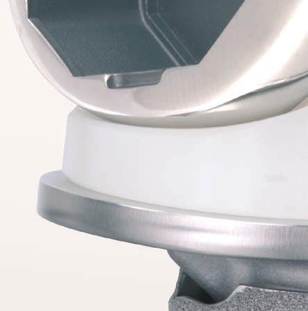
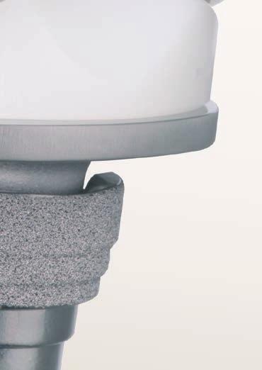
40 Assembling the Prosthesis Tibial Sleeve Assembly Note: It is imperative to assemble the sleeve prior to stem attachment. Note: Sleeves and step wedges can only be used together if using a 29 mm sleeve. Remove trial component in one piece (use as guide for assembly of implants). Figure 59 Place the M.B.T. Revision Tray on a firm, stable, padded surface. Set the tibial sleeve in an orientation that matches the prepared canal. Matching the orientation of the tray/sleeve trial is helpful in determining appropriate rotation of the final tibial tray/sleeve implant (Figure 58). The sleeve can rotate 20 degrees internally or externally. Figure 58 Using the sleeve impactor and a mallet, impact the sleeve onto the M.B.T. Revision Tray. Deliver several strikes to engage the two components (Figure 59). 37
41 Assembling the Prosthesis Wedge Assembly Note: To aid wedge assembly, attach wedge prior to stem attachment. Assemble the designated wedge to the tray and secure using the appropriate screw. Carefully tighten with the large T-handle torque driver until an audible click is discerned, ensuring a full and permanent interlock (Figure 60). Stem Component Assembly Attach the stem extension to the prosthetic tray using the two appropriate wrenches to ensure full engagement (Figure 61). Figure 60 Figure 61 38
42 Assembling the Prosthesis Implanting the Tibial Component Thoroughly cleanse the site with pulsatile lavage. Perforate with small drill holes on the prepared tibial surface to facilitate penetration of the bone cement (Figure 62). Pack residual small cavitary bone defects with cancellous autograft, if available, or allograft. Apply methyl methacrylate cement to the proximal tibial surface or directly to the underside of the tibial tray component. Figure 62 When a fluted stem or a fluted stem with a metaphyseal sleeve is used, ensure the medullary canal remains free of cement. Clear all extruded cement with a curette (Figures 63 and 64). Figure 63 Figure 64 39
43 Trial Reduction When femoral rotation is known, place the revision stem extension into the cone of the M.B.T. Revision implant. Seat the appropriate trial insert in the trial post/tray (Figure 65). The trial femoral component remains in place. Fully extend the knee to maintain pressure as the cement polymerises (Figure 66). After cement polymerisation, cement the femoral component. Revision Trial Post Note: With constrained femoral and tibial components in trial reduction, it may be appropriate to cement the tibial tray implant and the femoral implant using the insert trial. This will allow visibility of final rotation. Figure 65 Figure 66 40
44 Implant Assembly Sleeve and Stem Use Remove the trial components in reverse order and clean the site thoroughly using pulsatile lavage before implantation. Before prosthesis implantation proceeds, attach all augments, sleeves and modular stems to the femoral and tibial components. Implant assembly order (with sleeve and stem use): Femoral Adapter-to-femur Add posterior and distal augments if necessary Sleeve-to-stem Figure 67 Sleeve-to-Femoral Adapter Pass the appropriate SIGMA Femoral Adapter bolt, neutral or +/-2 mm, corresponding to the bushing selected for the A/P cutting block and notch/ chamfer guide, through the hole in the box of the distal femur and into the SIGMA Femoral Adapter (Figure 67). 41
45 Implant Assembly Sleeve and Stem Use Tighten the construct until the base of the adapter is flush with the femoral box. The three A/P etch marks on the base of the adapter implant should face laterally. Note: The Femoral stem bolt is not compatible with the SIGMA Femoral Adapter, as it is approximately 7 mm longer than the SIGMA Femoral Adapter bolt and will prevent the adapter from sitting flush on the femoral box. Attach the SIGMA Femoral Adapter holding clamp to the femoral implant and tighten it. The clamp provides the second moment arm needed to assemble the parts. Place the torque wrench over the SIGMA Femoral Adapter implant and move it clockwise to tighten the adapter to the femoral implant (Figure 68). The torque wrench has a deflection beam, which indicates when sufficient torque has been applied (Figure 69). Figure 68 Note: Torque the assembly to the 270 in. lb mark on the torque wrench to ensure assembly strength (Figure 69). Figure 69 42
46 Implant Assembly Sleeve and Stem Use Attach the augments using the wobble bits included in the augment package. Attach the femoral augments to the femoral component using the augment T-handle provided (Figures 70a and 70b). It may be necessary to use the T-handle extension in conjunction with the T-handle to attach the augments. Figure 70a Fully seat the augments on the component before tightening the screw thread mechanism. The augment assembly sequence chart is shown in Figure 71. For implant assembly with sleeve-only use, please see Appendix 5, page 63. Figure 70b Assembly Rules for Femoral Augmentation 1 For Size 1.5 Femoral Components Distal augmentation components in 4, 8 and 12 mm thicknesses. Assemble last. 2 For Size 4N PS Femoral Components Use size 2 distal and posterior augments. 3 For 4 mm/8 mm Augments They are fully interchangeable. If using 4 mm or 8 mm distal with posterior augment, install distal first. 4 For 12 mm/16 mm Distal Augments: Use 16 mm distal augment with TC3 femoral only. Femoral stem is indicated. On size 2, 2.5 and 3 femoral components, use 4 mm posterior. On size 4, 5 femoral component, may use 4 or 8 mm posterior Note: No size 6 augments available - use size 5 augment with size 6 femur. If using with posterior augment, install posterior augment first. Figure 71 43
47 Implant Assembly Sleeve and Stem Use To attach the universal stem to the revision sleeve, thread the stem onto the sleeve. Grasp the sleeve with the tibial sleeve clamp and use the stem extension wrench to grasp universal stem. Tighten as shown in Figure 72. Apply sufficient force to both wrenches to ensure that the stem is secure. Place the femoral component with the femoral adapter on a firm, stable, padded surface. Place the appropriate sleeve and stem construct on top of the Femoral Adapter assembly. Figure 72 Use the etch marks on the medial side of the adapter implant to assist in recreating sleeve rotation established during trial phase (Figure 73). Figure 73 44

48 Implant Assembly Sleeve and Stem Use Slide the femoral stem/sleeve impactor on top of the stem and forcefully apply three strikes with a mallet to engage the two component assemblies (Figure 74). Note: The femoral stem/sleeve impactor has two uses, one end for use of a sleeve without a stem extension and one end for a sleeve and stem combination. The definitive components are implanted in the following order: Tibial tray (with stem, sleeve or wedges) Femoral component (with stem, sleeve and augments) SIGMA Fixed Bearing or Rotating Platform CS or TC3 inserts Figure 74 Implant the femoral component using the Femoral Impactor (Figure 75). Figure 75 45
49 Preparation of the Patella Where replacement of the patellar component is indicated, it is important that the anteroposterior dimension be maintained and that adequate bone stock be preserved. Problems arise from inadequate, excessive or uneven resection resulting in an abnormal anteroposterior dimension to the complex, subsequent patellar tilt and implant wear. Free sufficient soft tissue at the prepatellar bursa to position calipers at the anterior cortex. Where residual bone stock is adequate, implantation of the replacement prosthesis is essentially routine. Where inadequate, patelloplasty may be indicated. Note: The normal anteroposterior patellar dimension is mm in the female, in the male (Figure 76) Figure 76 46
50 Preparation of the Patella Meticulous disruption of the bone/prosthesis interface is essential. It is performed with thin osteotomes and thin oscillating saw blades (Figure 77). Avoid excessive leverage to minimise possible fracturing. Position the patellar template that most adequately covers the prepared surface along the horizontal axis of the patella and firmly engaged. Fashion the three holes for the fixation pegs of the component with the appropriate drill (Figure 78). Depth is governed by the collar. Figure 77 Figure 78 47

51 Preparation of the Patella Implanting the Patellar Component Perform patella implantation when convenient. Cleanse the site with pulsatile lavage and apply bone cement. Insert the component into the prepared holes and position the patellar clamp. The clamp is designed to fully seat and stabilise the implant. Position it with the silicone O-ring centred over the articular surface of the implant and the metal backing plate against the anterior patellar cortex, avoiding skin entrapment. When snug, the handles are closed and held by the ratchet until polymerisation is complete (Figure 79). Avoid excessive compression as it can fracture osteopenic bone. Remove all extruded cement with a curette. Figure 79 48
52 Appendix 1 The Cemented Tibial Stem Extensions Cemented Stem Reamer Align the tibial tray and secure with two fixation pins inserted through the holes designated (Figure 1). Seat the M.B.T. revision drill bushing onto the tibia trial. Place in the posterior holes. Place the cemented drill bushing into the M.B.T. revision drill bushing (Figure 2). Use the cemented reamer to ream to the predetermined selected depths for tray only or the tray with a 30 or 60 mm cemented stem. Figure 1 Cemented Drill Bushing M.B.T. Revision Drill Bushing Remove the reamer and cemented bushing, leaving the tray trial and M.B.T. revision drill bushing in place (Figure 3). Note: Only a 13 mm diameter cemented stem should be used in conjunction with the M.B.T. revision tray to avoid a step off at the stem/ tray junction. Figure 2 Figure 3 49
53 Appendix 1 The Cemented Tibial Stem Extensions Tapered Reamer Assemble the revision reamer adapter onto the cemented tapered reamer. Modified Hudson Adapter Next, attach the modified Hudson adapter to the tapered reamer, if power reaming. Attach the appropriately sized cemented stem trial (13 x 30 mm or 13 x 60 mm) to the tapered reamer, if utilising a cemented stem extension (Figure 4). Ream until the revision reamer adapter is flush with the M.B.T. revision drill bushing (Figure 5). Revision Reamer Adapter Note: To avoid stem trial disengagement, do not reverse ream. Figure 4 Figure 5 50
54 Appendix 1 The Cemented Tibial Stem Extensions Tapered Cemented Stems Ream the canal with a reamer two sizes larger than the stem. For example, ream the medullary canal with a 15 mm reamer to implant a 13 mm tapered cemented stem, which allows for a 1 mm circumferential cement mantle at the proximal end of the stem. The cement mantle will be greater around the distal end of the cemented tapered stem (3 mm per side). This provides the following benefits: Thicker cement mantle distally helps assure that a circumferential mantle is present and reduces the possibility of thin or non-existent cement coverage of the stem distally. Stresses are greatest at the tip of the stem. A larger cement mantle is advantageous in dissipating these stresses. Thinner cement mantles are more prone to breakdown when exposed to higher stresses. Tibial Keel Preparation Place the knee in full extension and determine appropriate rotation of the tibial tray. Mark the appropriate rotation with electrocautery on the anterior tibial cortex at the centre and sides of the alignment handle. Assemble the appropriate stem trial to the M.B.T. revision tray trial and seat in the prepared bone bed. Figure 6 Impact the cemented keel punch if a cement mantle is desired or the press-fit keel punch if line-to-line contact is desired (Figure 6). Disconnect the universal handle leaving the keel punch in place for trial reduction (if appropriate). It is recommended that a cement restrictor be placed at the appropriate level prior to cementing the component. Use a cement gun to fill the canal with methyl methacrylate cement. 51
55 Appendix 2 Step Wedge Preparation Step Wedge Augmentation Resection for supplementary tibial augmentation may be based on the established position of the trial tray. Remove the femoral trial to provide greater access. Confirm rotational alignment of the tibial tray stem trial. Secure the tray with two fixation pins. Attach the tray trial wedge cutting attachment with the step wedge cutting guide to the trial tray. Slide the block forward to the anterior proximal tibia and secure in place with two Steinmann pins through the holes marked with (Figure 1). Unlock the block and slide the assembly out of the block. Disconnect the handle from the trial tray. Figure 1 Position the step wedge cutting block on the pins so the appropriate cutting surface (5, 10 or 15 mm step) is at the deficient condyle (Figure 2). Figure 2 52
56 Appendix 2 Step Wedge Preparation Step Wedge Cutting Block Trim the tibia accordingly with an oscillating saw so the cut does not extend beyond the central riser. Remove the block and pins (Figure 3). Assemble the trial wedge to the appropriate tibial tray trial (Figure 4) and introduce into the prepared site. Perform minimal correction with a bone file where indicated to ensure maximal contact. Figure 3 Figure 4 53
57 Appendix 2 Step Wedge Preparation Confirm positioning, alignment and security of the tray assembly. If there is old cement or sclerotic bone, relieve this first through the trial tray with a saw blade or burr prior to punching. Position the M.B.T. revision tibial keel punch at the tray and cancellous bone interface and impact into the keel configuration (Figure 5). Leave the punch in place and perform a final trial reduction if necessary. Note: Utilise the cemented keel punch when a cement mantle is desired. Alternative Step Wedge Preparation This is a free-hand resection. Assemble the wedge trial and stem trial to the tibial tray trial. Position the device slightly proximal to the planned resection level. Make a conservative free-hand wedge resection and then check cuts with the trials (Figure 6). Figure 5 Figure 6 54
58 Appendix 3 Thick Tray Preparation After impacting the cement or press-fit keel punch, remove the keel punch. Insert the M.B.T. thick tray trial adapter (15 or 25 mm) onto the tibial tray trial (Figures 1 and 2). Note: The tibial tray trial must be used with the thick tray adapters as the two pieces equal the appropriate sizing 15 or 25 mm. Perform the final trial reductions utilising the same technique as the standard M.B.T. Revision tray. Implant assembly and implantation is also the same as with the standard M.B.T. Revision tray. If utilising a wedge, refer to the Step Wedge Preparation in Appendix 2. Figure 1 Note: A tibial wedge can be used with all thick tray sizes, except for size 2. Sleeves may be used with all thick trays. Note: Due to the taper, trial with appropriate tray trial size. For example, a size 4 thick tray tapers down to a size 2. Use the size 2 tray trial with the size 4 thick tray adapter. The size 3 thick tray tapers down to a size 1. And the size 2 thick tray tapers down to a size 0. The size 0 tray trial can be found in the M.B.T. thick tray instrument set. Figure 2 55
59 Appendix 4 Femoral Trial Assembly - Stem Only Use Trial assembly order (with stem-only use, Figure 1): Thread the stem bolt trial through the trial femur and trial femoral adapter and tighten (Steps 1 and 2) Step 3 Add stem trial to trial assembly (Step 3) Add posterior and distal augment trials Pass the appropriate SIGMA Femoral Adapter stem bolt trial, neutral or +/-2 mm, corresponding to the bushing selected for the A/P cutting block and notch/chamfer guide, through the hole in the box of the distal femur. Thread the bolt trial through the SIGMA Femoral Adapter trial (Figure 1 - Step 1). Step 1 Step 2 Figure 1 56
60 Appendix 4 Femoral Trial Assembly - Stem Only Use Note: Trial bolt lengths are different for adapter/sleeve use than for adapter/stem-only use. Secure the adapter trial to the femoral trial by tightening the trial bolt with hex head screwdriver (Figure 1 - Step 2 on page 57). Assemble the stem trial, corresponding in size to the final diameter of the M.B.T. Revision reamer employed and to the established depth, to the femoral component/ SIGMA Femoral Adapter trial assembly (Figure 1 - Step 3 on page 56). Figure 2 Where augmentation is employed, assemble the appropriate trial distal and posterior augmentation components to the trial femur (Figure 2). Gently impact the trial component assembly into position with the femoral impactor. 57
61 Appendix 4 Femoral Implant Assembly - Stem Only Use Implant assembly order (with stem-only use): Femoral adapter-to-femur Stem implant-to-femoral adapter Add posterior and distal augments if necessary Attach the SIGMA Femoral Adapter holding clamp to the femoral implant and tighten it. The clamp provides the second moment arm needed to assemble the parts. Place the torque wrench over the SIGMA Femoral Adapter implant and move it clockwise to tighten the adapter to the femoral implant (Figure 3). The torque wrench has a deflection beam, which indicates when sufficient torque has been applied (Figure 4). Figure 3 Note: Torque the assembly to the 270 in. lb mark on the torque wrench to ensure assembly strength (Figure 4). Note: The Femoral stem bolt is not compatible with the SIGMA Femoral Adapter, as it is approximately 7 mm longer than the SIGMA Femoral Adapter bolt and will prevent the adapter from sitting flush on the femoral box. Figure 4 58


62 Appendix 4 Femoral Implant Assembly - Stem Only Use To attach the universal stem to the SIGMA Femoral Adapter, thread the stem onto the adapter. With the SIGMA Femoral Adapter holding clamp in place, use the stem extension wrench to grasp the universal stem. Tighten as shown in Figure 5. Apply sufficient force to both the SIGMA Femoral Adapter holding clamp and stem extension wrench to ensure that stem is secure. Figure 5 Implant the femoral component using the femoral impactor (Figure 6). Figure 6 59
63 Appendix 5 Femoral Trial Assembly - Sleeve Only Use Trial assembly order (with sleeve-only use, Figure 1) Thread the bolt trial through the trial femur and trial femoral adapter Step 2 Trial sleeve placed over adapter trial Loosely tighten assembly with hex head screwdriver, or by spinning sleeve Add posterior and distal augment trials if needed Seat trial assembly in femur Once sleeve trial has achieved proper orientation, tighten securely with hex head screwdriver Step 1 Pass the appropriate SIGMA Femoral Adapter sleeve bolt trial, neutral or +/-2 mm, corresponding to the bushing selected for the A/P cutting block and notch/chamfer guide, through the hole in the box of the distal femur. Thread the bolt trial through the SIGMA Femoral Adapter trial (Figure 1 - Step 1). Note: Trial bolt lengths are different for adapter/sleeve use than for adapter/stem-only use. Step 3 When preparing the femoral trial for use with a sleeve, assemble the sleeve trial, corresponding in size to the final broach employed, to the femoral component/sigma Femoral Adapter trial assembly. Tighten by turning the sleeve trial to initially engage the bolt trial thread. Figure 1 60
64 Appendix 5 Femoral Trial Assembly - Sleeve Only Use (continued) Step 2 Make sure to properly orient the sleeve trial with the narrow side facing medially. Use the hex head screwdriver to loosely secure the assembly (Figure 1 - Step 3). This mechanical connection to the adapter/femoral trial construct helps to ensure that the parts do not disassociate during use. Note: Please consult the anteroposterior width chart on page 65 of the Appendix to determine the sleeve/femur compatibility and the distance between the anterior chamfer and the anterior aspect of the sleeve. Where augmentation is employed, assemble the appropriate trial distal and posterior augmentation components to the trial femur. Step 1 Seat the femoral trial in the femur. The sleeve trial will achieve the rotation and orientation of final broach used. After the sleeve trial is seated securely in the metaphysis, securely tighten the bolt trial with the hex head screwdriver. Etch lines have been added to the medial side of the adapter trial and sleeve trials for a more accurate assessment of the sleeve s rotation during final implant assembly. Step 3 Figure 1 61
65 Appendix 5 Femoral Implant Assembly - Sleeve Only Use Implant assembly order (with sleeve-only use): Femoral adapter-to-femur Add posterior and distal augments if necessary Sleeve-to-femoral adapter Pass the appropriate SIGMA Femoral Adapter bolt, neutral or +/-2 mm, corresponding to the bushing selected for the A/P cutting block and notch/ chamfer guide, through the hole in the box of the distal femur and into the SIGMA Femoral Adapter (Figure 2). Note: The Femoral stem bolt is not compatible with the SIGMA Femoral Adapter, as it is approximately 7 mm longer than the SIGMA Femoral Adapter bolt and will prevent the adapter from sitting flush on the femoral box. Figure 2 Attach the SIGMA Femoral Adapter holding clamp to the femoral implant and tighten it. The clamp provides the second moment arm needed to assemble the parts. Place the torque wrench over the SIGMA Femoral Adapter implant and move it clockwise to tighten the adapter to the femoral implant (Figure 3). Figure 3 62
66 Appendix 5 Femoral Trial Assembly - Sleeve Only Use The torque wrench has a deflection beam, which indicates when sufficient torque has been applied (Figure 4). Remove the SIGMA Femoral Adapter holding clamp. Note: Torque the assembly to the 270 in. lb mark on the torque wrench to ensure assembly strength (Figure 4). Place the femoral component with the femoral adapter on a firm, stable, padded surface. Place the appropriate sleeve on top of the adapter. Slide the femoral stem/sleeve impactor on top of the sleeve and forcefully apply three strikes with a mallet to engage the two components (Figure 5). Figure 4 Note: The femoral stem/sleeve impactor has two uses, one end for the sleeve without a stem extension and one end for a sleeve and stem combination. Implant the femoral component using the femoral impactor. Figure 5 63
67 Appendix 6A Femoral Revision and M.B.T. Revision Tray Compatibility Femoral Components Size AP/57ML Size 2 56AP/60ML Size AP/63ML Size 3 61AP/66ML Size 4N 65AP/66ML Size 4 65AP/71ML Size 5 69AP/73ML Size 6 74AP/78ML PS TC3 PS TC3 PS TC3 PS TC3 PS ** PS TC3 PS TC3 PS ** M.B.T. Revision Trays Size 1 39AP/59ML Size AP/62ML Size 2 43AP/65ML Size AP/67ML Size 3 46AP/70ML Size 4 49AP/75ML Size 5 53AP/81ML Size 6 57AP/87ML ** TC3 femurs are not available in size 4N or size 6. Note: RP insert must match femur size for size. Note: For a size 4N femur, use a size 4 RP insert. M.B.T. Revision Trays Made of Cobalt Chrome Tray thickness is 4.8mm M.B.T. Revision Thick Trays Made of Cobalt Chrome Tray thickness is 15mm and 25mm All thick trays taper distally by two sizes to match tibial anatomy. M.B.T. Revision Thick Tray Sizing Chart Size Two Size Three Size Four Proximal size two size three size four Distal size zero (38AP/54ML) *** size one size two *** There are no size zero MBT Revision Step Wedges. 64
68 Appendix 6B Femoral Trial Assembly - Sleeve Only Use The following chart shows the distance (mm) between the anterior flange of a femoral component and the sleeve, based on the size of the component and the anteroposterior option chosen. Fields with an X denote that the sleeve, femur and offset option is not possible. Femoral Size and A/P Position 1.5 Ant 1.5 Neut 1.5 Post 2 Ant 2 Neut 2 Post 2.5 Ant 2.5 Neut 2.5 Post 3 Ant 3 Neut 3 Post 20 mm Size of sleeve (M/L) 31 mm mm X mm X mm X X Femoral Size and A/P Position 4 Ant 4 Neut 4 Post 5 Ant 5 Neut 5 Post 6 Ant 6 Neut 6 Post 20 mm Size of sleeve (M/L) 31 mm mm mm mm

69 Femoral Augmentation Trials & Inserts Cat. No C D B A E Description Cat. No. A Plug Puller B Mod Plus Torque Driver Extension C Mod Plus Torque Driver D Distal Augment Trial Size 1.5, 4 mm Distal Augment Trial Size 1.5, 8 mm Distal Augment Trial Size 1.5, 12 mm Distal Augment Trial Size 2 4, mm Distal Augment Trial Size 2 8, mm Distal Augment Trial Size 2, 12 mm Distal Augment Trial Size 2, 16 mm Distal Augment Trial Size 2.5, 4 mm Distal Augment Trial Size 2.5, 8 mm Distal Augment Trial Size 2.5, 12 mm Distal Augment Trial Size 2.5, 16 mm Distal Augment Trial Size 3, 4 mm Distal Augment Trial Size 3, 8 mm Distal Augment Trial Size 3, 12 mm Distal Augment Trial Size 3, 16 mm Distal Augment Trial Size 4, 4 mm Distal Augment Trial Size 4, 8 mm Distal Augment Trial Size 4, 12 mm Distal Augment Trial Size 4, 16 mm Distal Augment Trial Size 5, 4 mm Distal Augment Trial Size 5, 8 mm Distal Augment Trial Size 5, 12 mm Distal Augment Trial Size 5, 16 mm Description Cat. No. E Posterior Augmentation Trial Size 1.5, 4 mm Posterior Augmentation Trial Size 2, 4 mm Posterior Augmentation Trial Size 2, 8 mm Posterior Augmentation Trial Size 2.5, 4 mm Posterior Augmentation Trial Size 2.5, 8 mm Posterior Augmentation Trial Size 3, 4 mm Posterior Augmentation Trial Size 3, 8 mm Posterior Augmentation Trial Size 4, 4 mm Posterior Augmentation Trial Size 4, 8 mm Posterior Augmentation Trial Size 5, 4 mm Posterior Augmentation Trial Size 5, 8 mm

70 Femoral Revision Tray Base Tray Cat. No A B E G C D F Description Cat. No. A Femoral Notch Guide Size 2 mm Femoral Notch Guide Size 2.5 mm Femoral Notch Guide Size 3 mm Femoral Notch Guide Size 4 mm Femoral Notch Guide Size 5 mm B Femoral Locating Device Outrigger C Femoral Locating Device D Femoral Notch Guide Bushings (1mm increments) E Femoral Box Trial - STB Size 2 mm Femoral Box Trial - STB Size 2.5 mm Femoral Box Trial - STB Size 3 mm Femoral Box Trial - STB Size 4 mm Femoral Box Trial - STB Size 5 mm F Femoral Box Trials - TC3 Size 2 mm Femoral Box Trials - TC3 Size 2.5 mm Femoral Box Trials - TC3 Size 3 mm Femoral Box Trials - TC3 Size 4 mm Femoral Box Trials - TC3 Size 5 mm G Femoral Box Trial Screw Driver

71 Femoral Revision Tray Insert Cat. No A B C D E F G Description Cat. No. A Removable Handles B Femoral Rev A/P Cutting Block Size Femoral Rev A/P Cutting Block Size Femoral Rev A/P Cutting Block Size Femoral Rev A/P Cutting Block Size Femoral Rev A/P Cutting Block Size C Steinmann Pins D Distal Femoral Cutting Block E Femoral Distal Augment Spacers Size 4 mm Femoral Distal Augment Spacers Size 8 mm Femoral Distal Augment Spacers Size 12 mm Femoral Distal Augment Spacers Size 16 mm F Femoral A/P Rev Guide Bushings Size 5 Deg, Femoral A/P Rev Guide Bushings Size 5 Deg, +2/ Femoral A/P Rev Guide Bushings Size 7 Deg, Femoral A/P Rev Guide Bushings Size 7 Deg, +2/ G Stylus

72 SIGMA Femoral Adapter Instruments Top Tray Cat. No A G H I J K B L M C D E F N O P Q R Description Cat. No. A Universal Revision Femoral Broach Reamer B SIGMA Femoral Adapter Removable Shaft C Universal Revision Femoral Broach, 31 mm D Universal Revision Femoral Broach, 34 mm E Universal Revision Femoral Broach, 40 mm F Universal Revision Femoral Broach, 46 mm G Completion Revision Femoral Tapered Reamer H SIGMA Femoral Adapter Stem Bolt Trial, 2 mm Offset I SIGMA Femoral Adapter Stem Bolt Trial, Neutral J SIGMA Femoral Adapter Sleeve Bolt Trial, 2 mm Offset K SIGMA Femoral Adapter Sleeve Bolt Trial, Neutral L SIGMA Femoral Adapter Trial, 5 Deg M SIGMA Femoral Adapter Trial, 7 Deg N LCS/SIGMA Complete Femoral Sleeve Trial 20 mm O LCS/SIGMA Complete Femoral Sleeve Trial 31 mm P LCS/SIGMA Complete Femoral Sleeve Trial 34 mm Q LCS/SIGMA Complete Femoral Sleeve Trial 40 mm R LCS/SIGMA Complete Femoral Sleeve Trial 46 mm

73 SIGMA Femoral Adapter Instruments Bottom Tray Cat. No C D A B Description Cat. No. A SIGMA Femoral Adapter Torque Wrench B SIGMA Femoral Adapter Holding Clamp C Universal Revision Femoral Broach Handle D Completion Femoral Stem/Sleeve Impactor

74 M.B.T. Revision Prep Sterilisation Top Insert Cat. No A B C D E F G H I J L N K M Description Cat. No. A Cemented Stem Reamer 13 mm B 2 Deg Cutting Block C Reamer Adapter D Tibial Punch Press-fit E Tibial Punch Cemented F Pin Holder.125 in G SP2 Pin Puller H Drill Bushing I SP2 I.M. Rod 400 mm J I.M. Rod Handle K Cemented Busing 13 mm L Tapered Press-fit Reamer M Tapered Cemented Reamer N Steinmann Pins

75 M.B.T. Revision Prep Sterilisation Base and Bottom Insert Cat. No A F B G K L C H O M D I N P R S E J Q Description Cat. No. A 2 Deg Broach 29 mm B 2 Deg Broach 37 mm C 2 Deg Broach 45 mm D 2 Deg Broach 53 mm E 2 Deg Broach 61 mm F Sleeve Trial 29 mm G Sleeve Trial 37 mm H Sleeve Trial 45 mm I Sleeve Trial 53 mm J Sleeve Trial 61 mm K M.B.T. Revision Tibial Broach Handle L I.M. Tibial Alignment Device M Tibial Stylus N Sleeve Impactor O Femoral Sleeve/Stem Impactor P Universal Handle Q Tray Impactor R View Plate Size S View Plate Size T View Plate Size U View Plate Size V View Plate Size W View Plate Size X View Plate Size Y View Plate Size

76 Revision Reamers Sterilisation Tray Top Insert Cat. No A B C D F E G Description Cat. No. A Press-fit Rod Wrench B Sleeve Guide 12 mm C Sleeve Guide 14 mm D Reamer Depth Scale E Revision Femoral/Tibial/Sleeve Clamp F I.M. Initiator Drill Tibial 9 mm G M.B.T. Revisions Reamer 10 mm M.B.T. Revisions Reamer 11 mm M.B.T. Revisions Reamer 12 mm M.B.T. Revisions Reamer 13 mm M.B.T. Revisions Reamer 14 mm M.B.T. Revisions Reamer 15 mm

77 Revision Reamers Sterilisation Tray Base and Bottom Insert Cat. No AB AC A AD AE AF AG AH AI Description Cat. No. A M.B.T. Revision Reamer 16 mm M.B.T. Revision Reamer 17 mm M.B.T. Revision Reamer 18 mm M.B.T. Revision Reamer 19 mm M.B.T. Revision Reamer 20 mm M.B.T. Revision Reamer 21 mm M.B.T. Revision Reamer 22 mm M.B.T. Revision Reamer 23 mm M.B.T. Revision Reamer 24 mm B Reamer T-handle C Hudson Adapter D I.M. Rod Sleeve Guide 16 mm E I.M. Rod Sleeve Guide 18 mm F I.M. Rod Sleeve Guide 20 mm G I.M. Rod Sleeve Guide 22 mm H I.M. Rod Sleeve Guide 24 mm I I.M. Rod Sleeve Guide 26 mm

78 Revision Stem Trials & Instruments Sterilisation Tray Top Insert Cat. No A B E F G C D Description Cat. No. A Revision Femoral/Tibial/Sleeve Clamp B Tibial Cemented Trial 13 x C Tibial Cemented Trial 13 x D Stem Trial Extractor E Fluted Tibial Rod Trial 10 x Fluted Tibial Rod Trial 12 x Fluted Tibial Rod Trial 14 x Fluted Tibial Rod Trial 16 x Fluted Tibial Rod Trial 18 x Fluted Tibial Rod Trial 20 x Fluted Tibial Rod Trial 22 x Fluted Tibial Rod Trial 24 x F Fluted Tibial Rod Trial 10 x Fluted Tibial Rod Trial 12 x Fluted Tibial Rod Trial 14 x Fluted Tibial Rod Trial 16 x Fluted Tibial Rod Trial 18 x Fluted Tibial Rod Trial 20 x Fluted Tibial Rod Trial 22 x Fluted Tibial Rod Trial 24 x G Fluted Tibial Rod Trial 10 x Fluted Tibial Rod Trial 12 x Fluted Tibial Rod Trial 14 x Fluted Tibial Rod Trial 16 x Fluted Tibial Rod Trial 18 x Fluted Tibial Rod Trial 20 x Fluted Tibial Rod Trial 22 x Fluted Tibial Rod Trial 24 x

79 Revision Stem Trials & Instruments Sterilisation Tray Base and Bottom Insert Cat. No A B D E F C Description Cat. No. A Press-fit Rod Wrench B Tibial Cemented Trial 13 x C Tibial Cemented Trial 13 x D Fluted Tibial Rod Trial 10 x Fluted Tibial Rod Trial 12 x Fluted Tibial Rod Trial 14 x Fluted Tibial Rod Trial 16 x Fluted Tibial Rod Trial 18 x Fluted Tibial Rod Trial 20 x Fluted Tibial Rod Trial 22 x Fluted Tibial Rod Trial 24 x E Fluted Tibial Rod Trial 10 x Fluted Tibial Rod Trial 12 x Fluted Tibial Rod Trial 14 x Fluted Tibial Rod Trial 16 x Fluted Tibial Rod Trial 18 x Fluted Tibial Rod Trial 20 x Fluted Tibial Rod Trial 22 x Fluted Tibial Rod Trial 24 x F Fluted Tibial Rod Trial 10 x Fluted Tibial Rod Trial 12 x Fluted Tibial Rod Trial 14 x Fluted Tibial Rod Trial 16 x Fluted Tibial Rod Trial 18 x Fluted Tibial Rod Trial 20 x Fluted Tibial Rod Trial 22 x Fluted Tibial Rod Trial 24 x

80 M.B.T. Revision Tray Trials & Wedge Instruments Sterilisation Tray Top Insert Cat. No A B C D E F Description Cat. No. A M.B.T. Step Wedge Trial 5 mm Size M.B.T. Step Wedge Trial 5 mm Size M.B.T. Step Wedge Trial 5 mm Size M.B.T. Step Wedge Trial 5 mm Size M.B.T. Step Wedge Trial 5 mm Size M.B.T. Step Wedge Trial 5 mm Size M.B.T. Step Wedge Trial 5 mm Size M.B.T. Step Wedge Trial 5 mm Size 6/ B M.B.T. Step Wedge Trial 10 mm Size M.B.T. Step Wedge Trial 10 mm Size M.B.T. Step Wedge Trial 10 mm Size M.B.T. Step Wedge Trial 10 mm Size M.B.T. Step Wedge Trial 10 mm Size M.B.T. Step Wedge Trial 10 mm Size M.B.T. Step Wedge Trial 10 mm Size M.B.T. Step Wedge Trial 10 mm Size 6/ C M.B.T. Step Wedge Trial 15 mm Size M.B.T. Step Wedge Trial 15 mm Size M.B.T. Step Wedge Trial 15 mm Size M.B.T. Step Wedge Trial 15 mm Size M.B.T. Step Wedge Trial 15 mm Size M.B.T. Step Wedge Trial 15 mm Size M.B.T. Step Wedge Trial 15 mm Size M.B.T. Step Wedge Trial 15 mm Size 6/

81 M.B.T. Revision Tray Trials & Wedge Instruments Sterilisation Tray Base and Bottom Insert Cat. No B G C A D E F H I I B Description Cat. No. A M.B.T. Tibial Trial Size M.B.T. Tibial Trial Size M.B.T. Tibial Trial Size M.B.T. Tibial Trial Size M.B.T. Tibial Trial Size M.B.T. Tibial Trial Size M.B.T. Tibial Trial Size M.B.T. Tibial Trial Size B Tray Trials with Stem Size Tray Trials with Stem Size Tray Trials with Stem Size Tray Trials with Stem Size Tray Trials with Stem Size Tray Trials with Stem Size Tray Trials with Stem Size Tray Trials with Stem Size C Cut Block D Screw Driver E Wedge Cut Attachment F Alignment Handle G Alignment Rods H Trial Post I Torque Driver J Fixations Pins
THE P.F.C. SIGMA FEMORAL ADAPTER. Surgical Technique
 THE P.F.C. SIGMA FEMORAL ADAPTER Surgical Technique Contents P.F.C. Sigma Femoral Adapter and Revision Knee Surgery Introduction 2 Preoperative Planning 2 Overview 3 Surgical Technique Preparation of the
SIGMA REVISION KNEE AND M.B.T. REVISION TRAY
 SIGMA REVISION KNEE AND M.B.T. REVISION TRAY SURGICAL TECHNIQUE TABLE OF CONTENTS Surgical Technique Key Surgical Steps Summary 4 SIGMA Revision Knee/M.B.T. Revision Tray Knee Surgery 6 The SIGMA Revision
Rotating Hinge Knee System
 S-ROM NOILES Rotating Hinge Knee System Surgical Technique Table of Contents Surgical Technique Key Surgical Steps Summary 4 S-ROM NOILES Rotating Hinge Knee System 6 The S-ROM Hinge System Overview 7
S-ROM NOILES With High Performance Revision Instruments
 S-ROM NOILES With High Performance Revision Instruments This publication is not intended for distribution in the USA. SURGICAL TECHNIQUE CONTENTS Key Surgical Steps Summary 4 S-ROM NOILES Rotating Hinge
REVISION SURGICAL TECHNIQUE REVISION SURGERY FOR FAILED TOTAL-KNEE REPLACEMENT P. F. C. S I G M A K N E E S Y S T E M
 REVISION SURGICAL TECHNIQUE P. F. C. S I G M A K N E E S Y S T E M REVISION SURGERY FOR FAILED TOTAL-KNEE REPLACEMENT CONSULTING SURGEONS THOMAS S. THORNHILL, M.D. Orthopedist-in-Chief Brigham and Women
TRK REVISION KNEE Surgical Technique
 1 TRK REVISION KNEE Surgical Technique 1. 2. 3. 4. 5. 6. 7. 8. 9. 10. INTERCONDYLAR RESECTION...... page FEMORAL STEM...... page NON CEMENTED FEMORAL STEM...... page TRIAL FEMORAL COMPONENTS...... page
LCS COMPLETE Revision Knee System. Surgical Technique
 LCS COMPLETE Revision Knee System Surgical Technique Table of Contents LCS COMPLETE Revision System Surgical Technique Introduction 2 Pre-operative Planning 2 Surgical Technique 3 Intra-operative Evaluation
TOTAL KNEE ARTHROPLASTY SYSTEM
 SURGICAL TECHNIQUE TOTAL KNEE ARTHROPLASTY SYSTEM 90-SRK-700000 B.0 0 Contents 1. Implant Sizing 2. Surgical Technique a. Incision and Exposure b. Distal Femoral Resection c. Tibial Resection d. Femoral
Distal Cut First Femoral Preparation
 Surgical Technique Distal Cut First Femoral Preparation Primary Total Knee Arthroplasty LEGION Total Knee System Femoral preparation Contents Introduction...3 DCF femoral highlights...4 Preoperative planning...6
U2 PSA. Revision Knee. Surgical Protocol
 U2 PSA TM Revision Knee Surgical Protocol Table of Contents 1 Component Removal... 1 2 Tibial Preparation... 1 2.1 Tibial Canal Preparation... 1 2.2 Proximal Tibial Resection... 2 2.3 Non Offset Tibial
Zimmer NexGen MIS Tibial Component. Cemented Surgical Technique IMAGE TO COME
 Zimmer NexGen MIS Tibial Component Cemented Surgical Technique IMAGE TO COME Zimmer NexGen MIS Tibial Component Cemented Surgical Technique 1 Zimmer NexGen MIS Tibial Component Cemented Surgical Technique
Patella Planing System
 REFERENCE GUIDE AND SURGICAL TECHNIQUE Patella Planing System SPECIALIST INSTRUMENTS AN ONLAY PATELLA PREPARATION SYSTEM TECHNIQUE FOR PRIMARY PATELLAR RESURFACING The Specialist 2 Patellar Planer System
NEXGEN COMPLETE KNEE SOLUTION S A. Tibial Stem Extension & Augmentation Surgical. ATechnique
 NEXGEN COMPLETE KNEE SOLUTION ATechnique Tibial Stem Extension & Augmentation Surgical INTRODUCTION The NexGen Complete Knee Solution Intramedullary Tibial Instruments have been designed to provide an
Zimmer NexGen Tibial Stem Extension & Augmentation. Surgical Technique IMAGE TO COME. Stem Extensions and Augments
 Zimmer NexGen Tibial Stem Extension & Augmentation Surgical Technique IMAGE TO COME Stem Extensions and Augments Zimmer NexGen Tibial Stem Extension & Augmentation Surgical Technique 1 Zimmer NexGen Tibial
Zimmer NexGen Trabecular Metal Tibial Tray
 Zimmer NexGen Trabecular Metal Tibial Tray Surgical Technique Zimmer NexGen Trabecular Metal Tibial Tray Surgical Technique Give Bone A Solid Hold Zimmer NexGen Trabecular Metal Tibial Tray Surgical Technique
Zimmer NexGen RH Knee Primary/Revision. Surgical Technique
 Zimmer NexGen Primary/Revision Surgical Technique Zimmer NexGen Primary/Revision Surgical Technique INTRO Introduction The NexGen Rotating Hinge Knee () is designed for revision, difficult primary, and
Surgical Technique. Hinge Disassembly and Rebuild Technique
 Surgical Technique Hinge Disassembly and Rebuild Technique Revision Knee Arthroplasty Surgical Technique LEGION HK Hinge Knee System Introduction The LEGION HK Hinge Knee System has been designed as an
MIS Cemented Tibial Component
 MIS Cemented Tibial Component NexGen Complete Knee Solution Surgical Technique Table of Contents Surgical Exposure... 2 Finish the Tibia... 2 Position Based on Anatomic Landmarks... 3 Lateral Posterior
ANATOMIC SURGICAL TECHNIQUE. 5 in 1. Conventional instrumentation 07/11/2013
 ANATOMIC SURGICAL TECHNIQUE 5 in 1 Conventional instrumentation PRO.GB.933/1.0 Octobre 2013 2 Tibial step 3 Intramedullary technique - Based on the preoperative plan, drill the medullary canal with the
Revolution. Unicompartmental Knee System
 Revolution Unicompartmental Knee System While Total Knee Arthroplasty (TKA) is one of the most predictable procedures in orthopedic surgery, many patients undergoing TKA are in fact excellent candidates
Triathlon TS Knee System. Surgical Protocol
 Triathlon TS Knee System Surgical Protocol Triathlon TS Knee System Surgical Protocol Table of Contents Acknowledgments..........................................................2 Exposure...................................................................4
NATURAL MOTION TECHNOLOGY SURGICAL TECHNIQUE. EMPOWR 3D Knee. EMPOWR PS Knee
 NATURAL MOTION TECHNOLOGY EMPOWR 3D Knee EMPOWR PS Knee SURGICAL TECHNIQUE Contents System Features.... 3 Indications and Contraindications.... 4 Surgical Snap Shot.... Preoperative Planning.... Surgical
MRH Knee System Modular Peg Baseplate Surgical Protocol
 MRH Knee System Modular Peg Baseplate Surgical Protocol Using Monogram IM Revision Instruments 4 N 4 N Modular Rotating Hinge Knee System Using Monogram IM Revision Instruments Mr C R Howie FRCS Consultant
FLK167 02/08. Biomet UK Ltd Waterton Industrial Estate Bridgend, South Wales CF31 3XA, United Kingdom. Tel Fax:
 FLK167 02/08 Biomet UK Ltd Waterton Industrial Estate Bridgend, South Wales CF31 3XA, United Kingdom Tel. 01656 655221 Fax: 01656 645454 Premier Instrumentation CR or PS Surgical Technique Vanguard Premier
S U R G I C A L T E C H N I Q U E David A. McQueen, MD Return to Menu
 S U R G I C A L T E C H N I Q U E David A. McQueen, MD TOTAL KNEE INSTRUMENTS Wichita Fusion Nail Introduction...1 Preoperative Planning...2 Surgical Technique...3-8 Wichita Fusion Nail Surgical Technique
Profix. Total Knee System. As described by
 Profix Total Knee System P R I M A R Y P R O C E D U R E As described by Leo A. Whiteside, M.D. Associate Research Professor Washington University School of Medicine Director, Biomechanical Research Laboratory
Clinical Evaluation Surgical Technique
 Clinical Evaluation Surgical Technique Table of Contents EMPERION Specifications 3 EMPERION Surgical Technique 9 EMPERION Catalog 18 Nota Bene: This technique description herein is made available to the
Triathlon Knee System
 Triathlon Knee System Express Instruments Surgical Protocol Posterior Stabilized & Cruciate Retaining TriathlonKneeSystem Express Instruments Surgical Protocol Acknowledgments..........................................................2
NEXGEN COMPLETE KNEE SOLUTION. Revision Instrumentation Surgical Technique For Legacy Knee Constrained Condylar Knee
 NEXGEN COMPLETE KNEE SOLUTION Revision Instrumentation Surgical Technique For Legacy Knee Constrained Condylar Knee INTRODUCTION Revision total knee arthroplasty can be a very challenging task for any
Extramedullary Tibial Preparation
 Surgical Technique Extramedullary Tibial Preparation Primary Total Knee Arthroplasty LEGION Total Knee System Extramedullary tibial preparation Contents Introduction...2 EM tibial highlights...3 Preoperative
ELEOS Limb Salvage System
 ELEOS Limb Salvage System Surgical Technique Hinge Knee Replacement The ELEOS Limb Salvage System offers options for patients with significant bone loss due to cancer, trauma, or previous surgical procedures.
Resurfacing Distal Femur. Orthopaedic Salvage System
 Resurfacing Distal Femur Orthopaedic Salvage System Primary Arthroplasty OSS 3cm Resurfacing Distal Femur Distal Femoral Resection Drill and ream the distal femur in the following sequence: (Figure 1)
ANTERIOR REFERENCE NEXGEN COMPLETE KNEE SOLUTION. Multi-Reference 4-in-1 Femoral Instrumentation Anterior Reference Surgical Technique
 ANTERIOR REFERENCE NEXGEN COMPLETE KNEE SOLUTION Multi-Reference 4-in-1 Femoral Instrumentation Anterior Reference Surgical Technique For NexGen Cruciate Retaining & Legacy Posterior Stabilized Knees INTRODUCTION
NexGen Cruciate Retaining (CR) and Revision Instrumentation. Surgical Technique
 and Revision Instrumentation. Surgical Technique") NexGen Cruciate Retaining (CR) and Revision Instrumentation Surgical Technique Table of Contents Introduction... 4 Revision Arthroplasty... 4 Multi-Reference 4-in-1 Instrumentation System MICRO-MILL Instrumentation
NexGen Cruciate Retaining (CR) and Revision Instrumentation Surgical Technique Table of Contents Introduction... 4 Revision Arthroplasty... 4 Multi-Reference 4-in-1 Instrumentation System MICRO-MILL Instrumentation
Total Knee Original System Primary Surgical Technique
 Surgical Procedure Total Knee Original System Primary Surgical Technique Where as a total hip replacement is primarily a bony operation, a total knee replacement is primarily a soft tissue operation. Excellent
OPERATIVE TECHNIQUE SKS Total Knee Replacement
 OPERATIVE TECHNIQUE SKS Total Knee Replacement Femoral preparation A40577 1 2 5 1: Alignment rod A30049 + A30124 2: Centromedullary rod A40224 4: T-handle A40232 6: Femoral measuring device A40411 + A40414
CONTRIBUTING SURGEON. Barry Waldman, MD Director, Center for Joint Preservation and Replacement Sinai Hospital of Baltimore Baltimore, MD
 CONTRIBUTING SURGEON Barry Waldman, MD Director, Center for Joint Preservation and Replacement Sinai Hospital of Baltimore Baltimore, MD System Overview The EPIK Uni is designed to ease the use of the
Zimmer NexGen Rotating Hinge Knee Primary/ Revision
 Zimmer NexGen Rotating Hinge Knee Primary/ Revision Surgical Technique Designed for use in revision and difficult primary surgeries 1 INTRODUCTION The NexGen Rotating Hinge Knee Components are designed
Intramedullary Tibial Preparation
 Surgical Technique Intramedullary Tibial Preparation Primary Total Knee Arthroplasty LEGION Total Knee System Intramedullary tibial preparation Contents Introduction...2 IM tibial highlights...3 Preoperative
POSTERIOR REFERENCE NEXGEN COMPLETE KNEE SOLUTION. Multi-Reference 4-in-1 Femoral Instrumentation Posterior Reference Surgical Technique
 POSTERIOR REFERENCE NEXGEN COMPLETE KNEE SOLUTION Multi-Reference 4-in-1 Femoral Instrumentation Posterior Reference Surgical Technique For NexGen Cruciate Retaining & Legacy Posterior Stabilized Knees
Wichita Fusion Nail Surgical Technique. David A. McQueen, MD
 Wichita Fusion Nail Surgical Technique David A. McQueen, MD The patented design with a dual advantage Generates compression intraoperatively Innovative compression screw (a) locks femoral and tibial components
Scorpio TS Single Axis Revision Knee System. Scorpio Total Stabilizer Revision Knee System Surgical Protocol
 Scorpio TS Single Axis Revision Knee System Scorpio Total Stabilizer Revision Knee System Surgical Protocol Table of Contents Scorpio Total Stabilizer Revision Knee System Surgical Protocol Component
Constrained Posterior Stabilized (CPS) Surgical Technique
 Surgical Technique") Constrained Posterior Stabilized (CPS) Surgical Technique Constrained Posterior Stabilized (CPS) Surgical Technique INTRO Introduction The Constrained Posterior Stabilized (CPS) articular surfaces can
Constrained Posterior Stabilized (CPS) Surgical Technique Constrained Posterior Stabilized (CPS) Surgical Technique INTRO Introduction The Constrained Posterior Stabilized (CPS) articular surfaces can
Zimmer Trabecular Metal Ankle Interpositional Spacer and Trabecular Metal Ankle Fusion Spacer
 Zimmer Trabecular Metal Ankle Interpositional Spacer and Trabecular Metal Ankle Fusion Spacer Surgical Technique 2 Zimmer Trabecular Metal Ankle Interpositional Spacer and Trabecular Metal Ankle Fusion
Operative Technique. Constrained Condylar. The Right Track It s not just a road we re on, it s a trail we re blazing.
 Operative Technique Constrained Condylar The Right Track It s not just a road we re on, it s a trail we re blazing. TABLE OF CONTENTS Introduction...1 Design rationale...1 operative technique Overview...2
Proven Gen-Flex Revision Knee System. Surgical Protocol
 Proven Gen-Flex Revision Knee System Surgical Protocol Proven Gen-Flex Revision Knee System Surgeon Design Team The Proven Gen-Flex Revision Knee System Instrumentation and Surgical Protocol were developed
The information contained in this document is intended for healthcare professionals only.
 The information contained in this document is intended for healthcare professionals only. Triathlon Knee System Posterior Stabilized & Cruciate Retaining Table of Contents Acknowledgments.......................................................1
Knee. Surgical Protocol
 U2 TM PS CR Knee Surgical Protocol Table of Contents Pre-Operative Planning... Surgical Incision... 1 2 A. Femoral Preparation A.1. Pilot Hole... A.2. Femoral Valgus Angle Confirmation... A.3. Distal
NexGen Complete Knee Solution. Cruciate Retaining (CR) and Revision Instrumentation Surgical Technique for Cruciate Retaining Augmentable (CRA) Knees
 and Revision Instrumentation Surgical Technique for Cruciate Retaining Augmentable (CRA) Knees") NexGen Complete Knee Solution Cruciate Retaining (CR) and Revision Instrumentation Surgical Technique for Cruciate Retaining Augmentable (CRA) Knees INTRODUCTION This surgical technique document combines
NexGen Complete Knee Solution Cruciate Retaining (CR) and Revision Instrumentation Surgical Technique for Cruciate Retaining Augmentable (CRA) Knees INTRODUCTION This surgical technique document combines
Surgical Technique. VISIONAIRE Disposable Instruments for the LEGION Total Knee System
 Surgical Technique VISIONAIRE Disposable Instruments for the LEGION Total Knee System VISIONAIRE and LEGION Disposable instrument technique* Note: All disposable instruments are interchangeable with the
Arcos Modular Femoral Revision System. Broach and Calcar Proximal Bodies Surgical Technique
 Arcos Modular Femoral Revision System Broach and Calcar Proximal Bodies Surgical Technique Table of Contents Pre-operative Planning...2 Patient Positioning and Surgical Approach...2 Removal of a Cemented
Single Axis Revision Knee System
 Orthopaedics Scorpio TS Single Axis Revision Knee System Scorpio TS Trial Cutting Guide Surgical Protocol Orthopaedics Scorpio TS Single Axis Revision Knee System Scorpio TS Trial Cutting Guide Surgical
Zimmer FuZion Instruments. Surgical Technique (Beta Version)
") Zimmer FuZion Surgical Technique (Beta Version) INTRO Surgical Technique Introduction Surgical goals during total knee arthroplasty (TKA) include establishment of normal leg alignment, secure implant fixation,
Zimmer FuZion Surgical Technique (Beta Version) INTRO Surgical Technique Introduction Surgical goals during total knee arthroplasty (TKA) include establishment of normal leg alignment, secure implant fixation,
Surgical Technique. VISIONAIRE FastPak Instruments for the LEGION Total Knee System
 Surgical Technique VISIONAIRE FastPak Instruments for the LEGION Total Knee System VISIONAIRE FastPak for LEGION Instrument Technique* Nota Bene The technique description herein is made available to the
Zimmer MOST Options System
 Zimmer MOST Options System Surgical Technique Modular Options for Severe Bone Loss and Trauma Zimmer MOST Options System Surgical Technique 1 MOST Options System Surgical Technique Developed in conjunction
EXACTECH KNEE. Operative Technique ADDENDUM. Metaphyseal Cones. Surgeon focused. Patient driven. TM
 EXACTECH KNEE Operative Technique ADDENDUM Metaphyseal Cones Surgeon focused. Patient driven. TM TABLE OF CONTENTS INTRODUCTION...1 DESCRIPTION...1 DETAILED OPERATIVE TECHNIQUE Initial Preparation and
HP Knee Extraction Instrumentation. Product Overview
 HP Knee Extraction Instrumentation Product Overview HP Extraction Knee Instruments DePuy Orthopaedics is working with Symmetry Medical * to distribute Advanced Knee Extraction instruments. These instruments
Knee. Surgical Protocol
 U2 TM PS CR Knee Surgical Protocol Table of Contents Pre-Operative Planning... Surgical Incision... 1 2 A. Femoral Preparation A.1. Pilot Hole... A.2. Femoral Valgus Angle Confirmation... A.3. Distal
Exposure EXPOSURE. Exposure - Incision. Extend old incision proximally Expose virgin quadriceps tendon
 Exposure Aaron G Rosenberg MD Professor of Orthopedic Surgery Rush Medical College Chicago, Illinois Exposure - Incision Single incision can be used or modified Multiple longitudinal incisions favor the
Trabecular Metal Tibial Cone Surgical Technique
 Trabecular Metal Tibial Cone Surgical Technique Provides structural support in areas of bone loss Trabecular Metal Cone 1 Zimmer Trabecular Metal Tibial Cone Surgical Technique Table of Contents Overview
U2 KNEE SYSTEM. High Flexion Engineered
 U2 KNEE SYSTEM High Flexion Engineered TABLE OF CONTENTS Pre-Operative Planning...1 Surgical Incision...2 A. Femoral Preparation A.1. Pilot Hole...3 A.2. Femoral Valgus Angle Confirmation...4 A.3. Distal
AML Hip System. Design Rationale/ Surgical Technique
 AML Hip System Design Rationale/ Surgical Technique Design Rationale Evolution In 1977, DePuy Synthes Companies introduced the original cementless total hip. The AML Hip launched in order to solve one
Arcos Interlocking Distal Stem. Surgical Technique Addendum to the Arcos Modular Femoral Revision System
 Arcos Interlocking Distal Stem Surgical Technique Addendum to the Arcos Modular Femoral Revision System One Surgeon. One Patient. Over 1 million times per year, Biomet helps one surgeon provide personalized
Orthopedic Bone Nail System - Distal Femoral Nail Surgical Technique Manual
 Orthopedic Bone Nail System - Distal Femoral Nail Surgical Technique Manual Note: The surgical procedures should be performed under the guidance of qualified skilled orthopedic surgeons, and this surgical
TRUMATCH PERSONALIZED SOLUTIONS with the SIGMA High Performance Instruments
 TRUMATCH PERSONALIZED SOLUTIONS with the SIGMA High Performance Instruments Resection Guide System SURGICAL TECHNIQUE RESECTION GUIDE SURGICAL TECHNIQUE The following steps are an addendum to the SIGMA
ELEOS Limb Salvage System
 ELEOS Limb Salvage System Surgical Technique Total Femoral Replacement The ELEOS Limb Salvage System offers options for patients with significant bone loss due to cancer, trauma, or previous surgical procedures.
The Bio-Modular Choice Shoulder System,
 Surgical Technique The Bio-Modular Choice Shoulder System, designed for both total and hemiarthroplasty of the shoulder, has enjoyed nearly two decades of clinical success. The variety of head types and
1. Pre-Operative Planning Skin Incision and Arthrotomy
 Stage of Operation 1. Pre-Operative Planning --------------------------1 2. Skin Incision and Arthrotomy ------------------1 3. Femoral valgus angle confirmation ------------2 4. Distal Femur Cutting -----------------------------3
Trabecular Metal Primary Patella
 Trabecular Metal Primary Patella NexGen Complete Knee Solution Surgical Technique Table of Contents Introduction... 2 Prepare the Patella... 2 Patella Reamer Technique... 3 Insetting Technique... 5 Universal
A novel cementless option. Zimmer NexGen Trabecular Metal Primary Patella Surgical Technique
 A novel cementless option Zimmer NexGen Trabecular Metal Primary Patella Surgical Technique Zimmer Trabecular Metal Primary Patella 1 Zimmer NexGen Trabecular Metal Primary Patella Surgical Technique
ClassiQ. Scorpio. Anterior Referencing Surgical Protocol. Anterior Referencing. For use with Scorpio ClassiQ Instrument System
 Scorpio ClassiQ Anterior Referencing Surgical Protocol For use with Scorpio ClassiQ Instrument System For use with Scorpio ClassiQ Single Radius Total Knee System AR Anterior Referencing This document
Triathlon Knee System. Universal Baseplate Surgical Protocol
 Triathlon Knee System Universal Baseplate Surgical Protocol Table of Contents Acknowledgments..........................................................2 Introduction...............................................................2
LPS SYSTEM POCKET GUIDE
 LPS SYSTEM POCKET GUIDE Implants Procedural Uses Instruments & Trials L P S Limb Preservation System L P S Limb Preservation System The purpose of this document is to review the LPS (Limb Preservation
PIN GUIDE SYSTEM SURGICAL TECHNIQUE. with the SIGMA High Performance Instruments System. This publication is not intended for distribution in the USA.
 PIN GUIDE SYSTEM with the SIGMA High Performance Instruments System This publication is not intended for distribution in the USA. SURGICAL TECHNIQUE Pin Guide Surgical Technique The following steps are
GMRS Proximal Tibial Surgical Protocol
 Orthopaedics GMRS Proximal Tibial Surgical Protocol Global Modular Replacement System Acknowledgements Stryker would like to thank all of the surgeons for their contributions in developing the Global Modular
Anterior Cut First Surgical Technique
 Anterior Cut First Surgical Technique GENESIS II Anterior Cut First Surgical Technique Table of Contents Introduction....................................... 2 Preop Planning....................................
The information contained in this document is intended for healthcare professionals only.
 The information contained in this document is intended for healthcare professionals only. Orthopaedics GMRS Proximal Tibial Surgical Protocol Global Modular Replacement System Acknowledgements Stryker
Triathlon Knee System Universal Baseplate Surgical Protocol
 Triathlon Knee System Universal Baseplate Surgical Protocol Triathlon Knee System Universal Baseplate Surgical Protocol Table of Contents Acknowledgments... 2 Introduction... 2 Assembly Instructions...
Constrained Posterior Stabilized (CPS)
") Constrained Posterior Stabilized (CPS) Persona The Personalized Knee Surgical Technique Table of Contents Introduction... 2 Constraint Options Initial Knee Assessment... 3 Femoral Box Cut CPS Tibial Bearing
Constrained Posterior Stabilized (CPS) Persona The Personalized Knee Surgical Technique Table of Contents Introduction... 2 Constraint Options Initial Knee Assessment... 3 Femoral Box Cut CPS Tibial Bearing
TRIAL COMPONENTS SURGICAL TECHNIQUE REAMING THE TIBIAL AND FEMORAL INTRAMEDULLARY CANAL
 Ref. no. 99.27.2TRIALS TRIAL COMPONENTS SURGICAL TECHNIQUE CLINICAL INDICATION This technique is indicated in the case of revisions with significant bone loss when minimal or any resection of bone is required.
NexGen LPS Fixed Bearing Knee. Surgical Technique
 NexGen LPS Fixed Bearing Knee Surgical Technique Table of Contents Introduction...2 Preoperative Planning...2 Surgical Technique...3 Step One: Align the Tibia...3 MICRO-MILL Hand Piece Assembly and Usage
NexGen CR-Flex Fixed Bearing Knee. Surgical Technique
 NexGen CR-Flex Fixed Bearing Knee Surgical Technique Table of Contents Introduction...2 Preoperative Conditioning... 3 Preoperative Planning... 3 Surgical Technique...4 Incision and Exposure... 4 Femoral
Persona. The Personalized Knee. Trabecular Metal Tibia. Surgical Technique
 Persona The Personalized Knee Trabecular Metal Tibia Surgical Technique Table of Contents Resect the Tibia... 4 Size and Finish the Tibia... 4 Trial Fit... 6 Component Implantation... 7 Inserter/Implant
Trabecular Metal Femoral Component. Surgical Technique
 Trabecular Metal Femoral Component Surgical Technique INTRO Trabecular Metal Femoral Component Surgical Technique Introduction The Persona Trabecular Metal Femoral Component is designed to unite stable
Premier Total Knee Instrumentation
 Premier Total Knee Instrumentation Vanguard Complete Knee System Surgical Technique Table of Contents Indications and Contraindications... 3 Introduction... 4 Patient Selection Preoperative Planning Approaches...
Surgical Technique Final Trial Reduction and Component Implantation of
 Surgical Technique Final Trial Reduction and Component Implantation of TC *smith&nephew TC-PLUS PRIMARY Fixed Bearing TC-PLUS PRIMARY Fixed Bearing Final Trial Reduction and Component Implantation of
SCORE Revision. Revision Total Knee Arthroplasty Cemented. Surgical Technique With Conventional Instrumentation Primary cases
 SCORE Revision Revision Total Knee Arthroplasty Cemented Surgical Technique With Conventional Instrumentation Primary cases SCORE REVISION FOR PRIMARY CASES The SCORE Revision is a revision total knee
PRIMARY POROUS PATELLA WITH TRABECULAR METAL. Surgical Technique
 PRIMARY POROUS PATELLA WITH TRABECULAR METAL Surgical Technique 1 SURGICAL TECHNIQUE FOR NEXGEN PRIMARY POROUS PATELLA * WITH TRABECULAR METAL CONTENTS PREPARE THE PATELLA............... 2 Patella Reamer
Unicondylar Surgical Technique
 Unicondylar Surgical Technique Contents Indications, Contra-indications and X-ray Templating 2 Approach and Exposure 3 Proximal Tibial Resection 4 Tibial Jig Alignment 6 Tibial Sizing 9 Balancing 10 Distal
Approach Patients with Confidence
 Surgical Technique Approach Patients with Confidence The ACTIS Total Hip System is the first DePuy Synthes stem specifically designed to be utilized with tissue sparing approaches, such as the anterior
NEXGEN COMPLETE KNEE SOLUTION
 NEXGEN COMPLETE KNEE SOLUTION Surgical Technique for the Legacy Knee LPS-Flex Mobile Bearing Knee This device is not available for commercial distribution in the U.S. Implants and Surgical Technique developed
AGC Total Knee System. Concise Surgical Technique Featuring EquiFlex Instrumentation
 AGC Total Knee System Concise Surgical Technique Featuring EquiFlex Instrumentation AGC TOTAL KNEE SYSTEM Concise Surgical Technique Instrumentation Disclaimer This brochure provides a description of the
14 mm x +30 mm Stem Extension
 14 mm x +30 mm Stem Extension Persona The Personalized Knee Surgical Technique Table of Contents Introduction...2 Preoperative Planning Surgical Approach Patient Preparation Magnet Usage Symbols Screw/Pin
Contact your Zimmer representative or visit us at
 Please refer to the package inserts for complete product information, including contraindications, warnings, precautions, and adverse effects. Contact your Zimmer representative or visit us at www.zimmer.com
LCS COMPLETE SURGICAL TECHNIQUE. MILESTONE Instruments with MBT Tray Preparation
 LCS COMPLETE MILESTONE Instruments with MBT Tray Preparation SURGICAL TECHNIQUE CONTENTS Preface 2 Surgical Concepts 3 Instruments 4 Surgical Technique Summary 6 Surgical Technique 8 Preparation 8 Incision
Technique Guide. *smith&nephew N8TIVE ACL Anatomic ACL Reconstruction System
 Technique Guide *smith&nephew N8TIVE ACL Anatomic ACL Reconstruction System N8TIVE ACL System The N8TIVE ACL Anatomic Reconstruction System provides a novel and simple approach to ACL repair. The N8TIVE
INSTRUMENTS. Measured Resection Classic Surgical Technique
 INSTRUMENTS Measured Resection Classic Surgical Technique RECOVERY FUNCTION SURVIVORSHIP DePuy believes in an approach to knee arthroplasty that places equal importance on recovery, function and survivorship.
INSTRUMENTS. Balanced Surgical Technique
 INSTRUMENTS Balanced Surgical Technique Contemporary total knee arthoplasty demands high performance instrumentation that provides enhanced efficiency, precision and flexibility. Through a program of continuous
The information contained in this document is intended for healthcare professionals only.
 The information contained in this document is intended for healthcare professionals only. Orthopaedics GMRS Distal Femoral Surgical Protocol Global Modular Replacement System Acknowledgements Stryker would