MICA. Minimally Invasive Foot Surgery CHEVRON OSTEOTOMY SURGIC AL TECHNIQUE
|
|
|
- Lydia Walker
- 5 years ago
- Views:
Transcription


1 MICA Minimally Invasive Foot Surgery CHEVRON OSTEOTOMY SURGIC AL TECHNIQUE
2
3 Contents Chapter 1 4 Introduction Chapter 2 5 Indications and Warnings Chapter 3 6 Patient Positioning and Set Up Chapter 4 7 Chevron Osteotomy Surgical Technique 7 Patient Presentations 7 Surgical Approach 7 Osteotomy with Burr 8 Targeting Guide 9 Osteotomy 10 Target Guide 10 Fixation of the Osteotomy 12 Lateral Release Appendix A 13 Explant Information 13 Postoperative Management Appendix B 14 Ordering Information Wright recognizes that proper surgical procedures and techniques are the responsibility of the medical professional. The following guidelines are furnished for information purposes only. Each surgeon must evaluate the appropriateness of the procedures based on his or her personal medical training, experience, and patient condition. Prior to use of the system, the surgeon should refer to the product Instructions For Use package insert for additional warnings, precautions, indications, contraindications and adverse effects. Instructions For Use package inserts are also available by contacting the manufacturer. Contact information can be found on the back of this surgical technique and the Instructions For Use package inserts are available on wright.com under the link for Prescribing Information. Please contact your local Wright representative for product availability. 3

4 Introduction chapter 1 The MICA Screw System is a cannulated fully-threaded titanium alloy screw system that is indicated for use in bone reconstruction, osteotomy, arthrodesis, joint fusion, fracture repair, and fracture fixation of bones appropriate for the size of the device. With self-drilling and self-tapping headless compression screws FIGURE 1 in diameters of 3.0mm and 4.0mm (Table 1), the MICA Screw System provides extensive versatility for surgical procedures of the foot within one comprehensive system. TABLE 1: AVAILABLE DIAMETERS AND LENGTHS FIGURE 1 MICA Fully Threaded Screw FIGURE 2 Colored banding on the pilot drill, driver and countersink simplifies identification with screw size. HEADLESS SCREWS Diameter 3.0mm 4.0mm System Basics Screw Lengths 32mm, 34mm, 36mm, 38mm, 40mm, 42mm, 44mm, 46mm, 48mm 38mm, 40mm, 42mm, 44mm, 46mm, 48mm, 50mm, 52mm, 54mm, 56mm, 58mm, 60mm The MICA Screw System offers the simplicity of self-tapping cannulated compression screws in 3.0mm and 4.0mm diameters. All MICA Screws are manufactured from titanium alloy (Ti 6Al-4V) to provide consistent strength. Screws are color-coded by diameter to easily identify associated instrumentation (Table 2). Pilot Drills, Countersinks, and Drivers have corresponding colorcoded banding to match screw diameter, simplifying the pairing of instrumentation with screw selection. FIGURE 2 Cannulated drill bits are included for use in hard cortical bone, when an oblique approach is desired, or when bicortical fixation is required. Cannulated Countersinks are provided to recess screw heads into the cortex of the bone. TABLE 2: HEADLESS SCREWS Screw Diameter Color Pilot Drill Countersink Driver K-wire 3.0mm Brown 2.2mm 2.8mm 2.0mm Hex 0.9mm 4.0mm Blue 3.0mm 4.0mm 2.5mm Hex 1.4mm 4 Chapter 1 Introduction
5 Indications and Warnings chapter 2 Indications The MICA Screw is indicated for fixation of bone fractures or for bone reconstruction. Examples include: Mono or Bi-Cortical osteotomies in the foot or hand Distal or Proximal metatarsal or metacarpal osteotomies Weil osteotomy Fusion of the first metatarsophalangeal joint and interphalangeal joint Fixation of osteotomies for Hallux Valgus treatment (such as Scarf, Chevron, etc.) Akin type osteotomy Arthrodesis base first metatarsal cuneiform joint to reposition and stabilize metatarsus varus primus Calcaneus/cuboid arthrodesis Talar/navicular arthrodesis Contraindications General Surgical Contraindications: Infection; Physiologically or psychologically inadequate patient; Irreparable tendon system; Possibility for conservative treatment; Growing patients with open epiphyses; Patients with high levels of activity. Prior to use of the system, the surgeon should refer to the product instructions for use package insert for warnings, precautions, indications, contraindications and adverse effects. Instructions for use package inserts are also available by contacting the manufacturer. Contact information can be found on the back of this surgical technique and the instructions for use package inserts are available on wright.com under the link for Prescribing Information. Chapter 2 Indications and Warnings 5


6 Patient Positioning 3 and Set Up NOTE: Patient positioning based on right handed Health Care Professional. Patient positioning equipment set-up is extremely important when performing any MICA procedure. The patient s feet should be positioned off the end of the table, enabling ease of access for x-ray, thereby allowing biplanar x-ray views throughout the procedure. FIGURE 3 The x-ray itself should come in from the patient s right allowing rotation of the c-arm to achieve Anterior-Posterior and Lateral views of each foot. FIGURE 4 The Burr Machine is positioned to the patient s left. FIGURE 5 This set-up enables free movement of the surgeon around the patient s feet, to either stand at the side or end of the table as the operation demands. The position of the equipment is independent of whether the operative side is left or right. FIGURE 6 The positioning of equipment can be mirrored for a left-handed surgeon. FIGURE 3 FIGURE 4 FIGURE 5 FIGURE 6 6 Chapter 3 Patient Positioning and Set Up
 57SR0220 2mm x 20mm MICA Burr NOTE: Burrs were designed to be used at 6000 RPM.")
, a stab incision is placed over the dorso-medial aspect of the proximal edge of the flare of the medial eminence. The placement of this incision is vital.")
 is used to carefully create a working area for the burr.")
7 Surgical Technique 4 Chevron Osteotomy 2mm x 20mm MICA Burr (57SR0220) Patient Presentations: Hallux valgus deformity Surgical Approach 01SM64 MICA Blade 57S0MI06 MICA Blade Handle (part of a set) 57S0MI06 Straight Periosteal Elevator (part of a set) 57SR0220 2mm x 20mm MICA Burr NOTE: Burrs were designed to be used at 6000 RPM. Higher rotation could cause increased risk of bone necrosis or soft tissue damage. Using the MICA Blade (01SM64), a stab incision is placed over the dorso-medial aspect of the proximal edge of the flare of the medial eminence. The placement of this incision is vital. The incision must avoid the dorso-medial cutaneous nerve to the Hallux; if palpable, this nerve should be marked before placing the incision. Once the incision is made, the Straight Periosteal Elevator (57S0MI06) is used to carefully create a working area for the burr. This is created over the dorsal surface of M1 but not on the plantar surface, as this may risk damage to the blood supply of the M1 head. Osteotomy with Burr 2mm x 20mm MICA Burr (57SR0220) The plane of the osteotomy is defined by the entry cut of the burr into the metatarsal. It is from this entry cut that the dorsal and plantar limbs of the chevron are then made. In other words, this first entry of the burr creates the apex of the chevron. It must be noted that the osteotomy will remove 2mm of bone. This needs to be accounted for when deciding on the plane of the osteotomy. The Burr (57SR0220) should generally be perpendicular to the first metatarsal and angled approximately 20 º plantarly, allowing for any lost length and height to be regained when lateralizing the metatarsal head. It is wise to view initial osteotomy planes under x-ray. FIGURES 7 AND FIGURE 7 FIGURE 8 Chapter 4 Surgical Technique - Chevron Osteotomy 7
, follow the directions for use below.")
 into the")
 over the burr and place the k-wire alignment holes proximal of")

 through the Targeting Guide in the preferred plane and direction, and into the base")
 is then inserted using the Targeting Guide.")

8 Targeting Guide ( ) NOTE: Two different styles of targeting guide are available for use with this system. If using the first ( ), follow the directions for use below. If using the second ( ), follow the directions for use following the Osteotomy section below. FIGURE 9 Once the correct plane has been determined, insert the 2 X 20mm MICA Burr (57SR0220) into the medial cortex. Once the burr has exited the lateral cortex, stop and remove the hand piece from the burr. Then, place the Targeting Guide ( ) over the burr and place the k-wire alignment holes proximal of the TMT1 joint. FIGURE 9 FIGURE 10 FIGURE 11 FIGURE 13 NOTE: The more dorsal alignment holes can be used as an external visual check of your k-wire positioning. FIGURE 10 Using x-ray guidance, insert the 1.4mm k-wire (DSDS1014S) through the Targeting Guide in the preferred plane and direction, and into the base of the first metatarsal. The 1.4mm wire should exit proximal to the burr and then be left in situ. FIGURE 11 A 0.9mm k-wire (DSDS1009S) is then inserted using the Targeting Guide. This wire should be distal and parallel to the 1.4mm k-wire. Again, this wire is inserted proximal to the Burr and left in situ until the osteotomy and lateralization are completed. FIGURES 12 and 13 The Burr (57SR0220) is now removed from the metatarsal and the Targeting Guide can slide off the k-wires. FIGURE 14 FIGURE 12 FIGURE Targeting Guide 8 Chapter 4 Surgical Technique - Chevron Osteotomy
 into the stab incision portal and bi-cortical osteotomy hole.")


, the metatarsal head can be displaced along its defined plane.")

9 Osteotomy with Burr The dorsal osteotomy is the first limb to be created. Insert the 2 x 20mm MICA burr (57SR0220) into the stab incision portal and bi-cortical osteotomy hole. FIGURE 15 Once the burr exits the lateral cortex of the metatarsal, rotate and lift the hand piece so that the burr cuts dorsally until you have completed the dorsal limb of the osteotomy. FIGURE 16 FIGURE 15 NOTE: Is it important to rotate AND lift while cutting to both prevent any thermal injury to the skin/soft tissues, and prevent plantar extension of the osteotomy on the near cortex. Imagine the skin portal as the fulcrum point for rotation. The Plantar limb is created by placing the burr back to the original bi-cortical position. Then, under controlled power, slowly translate the burr plantarly and at the same time rotate the hand piece dorsally and laterally (so the burr moves in a plantar medial direction) until the burr exits the medial cortex. FIGURE 17 FIGURE 16 NOTE: After completing the Plantar osteotomy, the hand piece should be dorsal to the Hallux to ensure the burr has fully exited the medial cortex of the metatarsal. Once the cut is complete (confirmed by the motion at the osteotomy site), the metatarsal head can be displaced along its defined plane. Displacement is achieved by placing the Straight Periosteal Elevator (57S0MI06), Elevator ( ) or First Met Translator (577000MT) through the existing portal, into the diaphysis of the proximal fragment and levering the distal fragment laterally. FIGURE 18 NOTE: Care must be taken not to fracture the medial cortex of the proximal fragment. To avoid this, make sure the elevator is inserted sufficiently deeply into the diaphysis. FIGURE 17 NOTE: Elevation of the metatarsal head is avoided by ensuring that the straight periosteal elevator remains directly over the medial eminence during displacement. FIGURE Elevator MT First Met Translator FIGURE 18 Chapter 4 Surgical Technique - Chevron Osteotomy 9


 through the K-Wire Sleeve and into the base of the first metatarsal.")
 into the medial hole of the Target Guide. A 0.")


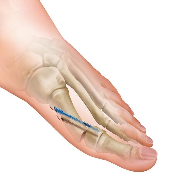
10 Target Guide ( ) Place the Target Guide ( ) into the osteotomy and orient so that the tip is located at the desired exit point of the 4mm MICA Screw. FIGURE 19 FIGURE 19 FIGURE 20 FIGURE 21 FIGURE 22 NOTE: The more dorsal alignment holes can be used as an external visual check of your k-wire positioning. Insert a 1.4mm K-Wire Sleeve ( ) into the lateral hole of the Target Guide. Use the MICA Blade to create a small incision through which to insert the K-Wire Sleeve. Advance the Sleeve until the tip contacts the medial aspect of the first metatarsal. Insert a 1.4mm K-Wire (DSDS1014S) through the K-Wire Sleeve and into the base of the first metatarsal. K-Wire advancement should be stopped just short of the osteotomy. FIGURE 20 Insert a 0.9mm K-Wire Sleeve ( ) into the medial hole of the Target Guide. A 0.9mm K-Wire (DSDS1009S) is then inserted through the 0.9mm K-Wire Sleeve until the tip is just proximal to the osteotomy. FIGURE 21 Both sleeves are now removed from the Target Guide. FIGURE 22 The Guide may be removed from the foot by rotating medially so that the K-Wires slide through the slot in the Target Guide, and then rotating the Target Guide dorsally to remove the tip from the incision site. FIGURE 23 As described previously, once the Target Guide is removed, the osteotomy may be displaced laterally using the Straight Periosteal Elevator, Elevator, or First Met Translator by inserting the tip through the existing portal, into the diaphysis of the proximal fragment and levering the distal fragment laterally. FIGURE 24 Fixation of the Osteotomy The osteotomy is fixed internally with 2 cannulated screws. FIGURE 23 STEP 1 K-WIRE Once the lateralization and plantarization have been achieved, drive the 1.4mm and 0.9mm k-wires into the metatarsal head. (These are already positioned from targeting step). FIGURE Target Guide K-Wire Sleeve 1.4mm K-Wire Sleeve 0.9mm Gold: 0.9mm k-wire Blue: 1.4mm k-wire FIGURE 25 NOTE: The proximal/lateral 1.4mm k-wire should sit in the lateral half of the metatarsal head and the distal/medial 0.9mm wire should sit in the medial half of the metatarsal head. Both 1.4mm and 0.9mm k-wires should not breach the MTP Joint. FIGURE Chapter 4 Surgical Technique - Chevron Osteotomy

 and the 2.8mm Countersink (DSDS1028S). NOTE: Alternatively, non-cannulated drills are available. 2.2mm (57S00122) for the 3.0mm MICA Screw and 3.")

 attached to the Handle (45765001). The 3mm MICA screw will be inserted over the 0.9mm k-wire using the 2.")

11 STEP 2 MEASURE Use the MICA Depth Gauge (577000DG) to determine which size 4mm MICA screw is needed for the proximal/lateral 1.4mm k-wire. Repeat for the distal/medial 3mm MICA screw to be placed over the 0.9mm k-wire. FIGURE 26 FIGURE DG MICA Depth Gauge 57S mm Cannulated Drill 57S mm Cannulated Drill STEP 3 DRILL For the 4mm MICA Screw, use the 3.0mm Cannulated Drill (57S00030) and the 4.0mm Countersink (57S01040). For the 3mm MICA screw, use the 2.2mm Cannulated Drill (57S00022) and the 2.8mm Countersink (DSDS1028S). NOTE: Alternatively, non-cannulated drills are available. 2.2mm (57S00122) for the 3.0mm MICA Screw and 3.0mm (57S00130) for the 4.0mm MICA Screw. NOTE: For greater security, it is recommended to pass the k-wire distally through the skin and attach it to a clip to prevent it from getting stuck in the cannulated drills. FIGURE 28 57S mm Countersink DSDS1028S 2.8mm Countersink 57S mm Solid Drill 57S mm Solid Drill STEP 4 SCREW The 4mm MICA screw will be inserted over the 1.4mm k-wire using the 2.5mm Hex Driver (57S02025) attached to the Handle ( ). The 3mm MICA screw will be inserted over the 0.9mm k-wire using the 2.0mm Hex Driver (57S02020), attached to the Handle ( ). FIGURE 27 FIGURE 27 Insert each screw until the angled head is flush with the medial aspect of the first metatarsal. FIGURE 28 NOTE: It is important to remember to align the line on the Hex Driver with the beveled head of the MICA screw to allow for greater control when inserting the screw. This alignment allows the user to determine when the MICA screw is seated flush. X-ray will also confirm this. FIGURE 29 57S mm Hex Driver FIGURE 29 57S mm Hex Driver Handle Chapter 4 Surgical Technique - Chevron Osteotomy 11
 is angled parallel to the joint, with the blade facing laterally, so as not to damage the articular surfaces.")
 is divided on the plantar aspect of the joint.")
12 Lateral Release If required, this is performed through a stab incision over the lateral extreme of the dorsal aspect of the 1st MTP joint line. The MICA Blade (01SM64) is angled parallel to the joint, with the blade facing laterally, so as not to damage the articular surfaces. The blade is then deepened towards the plantar lateral aspect of the 1st MTPJ. FIGURE 30 The lateral head of the Flexor hallucis brevis (lateral sesamophalangeal ligament) is divided on the plantar aspect of the joint. FIGURE 31 This is a thickening of the plantar lateral capsule of the joint (plantar plate) and has a gritty quality when cut. Do not continue the cut laterally, otherwise the lateral collateral ligament will be cut. The x-ray may help to guide the MICA Blade (01SM64) positioning and a varus movement of the hallux against the correctly positioned blade completes the cut. X-ray views are helpful to confirm the release by observing a static lateral sesamoid on varus movement of the hallux. In mild to moderate Hallux valgus deformities, this is usually sufficient release of the lateral soft tissues. Depending on surgeon preference, with greater deformities, the adductor hallucis and the sesamoid-metatarsal ligament can also be divided. Release of lateral sesamophalangeal ligament Sesamoid bones FIGURE 30 MICA blade position FIGURE Chapter 4 Surgical Technique - Chevron Osteotomy
13 Explant Information Appendix A Removal of the 3.0mm screw may be performed by using the 2.0mm Hex Driver (57S02020). Removal of the 4.0mm screw may be performed by using the 2.5mm Hex Driver (57S02025). If removal of the implant is required due to revision or failure of the device, the surgeon should contact the manufacturer using the contact information located on the back cover of this surgical technique to receive instructions for returning the explanted device to the manufacturer for investigation. POSTOPERATIVE MANAGEMENT Postoperative care is the responsibility of the medical professional. Appendix A Explant Information 13
14 Ordering Information Appendix B MICA Screws Part Number 3.0mm MICA Screws 57S S S S S S S S S mm MICA Screws 57S S S S S S S S S S S S34060 Description MICA Screw 3.0mm x 32mm MICA Screw 3.0mm x 34mm MICA Screw 3.0mm X 36mm MICA Screw 3.0mm X 38mm MICA Screw 3.0mm X 40mm MICA Screw 3.0mm X 42mm MICA Screw 3.0mm X 44mm MICA Screw 3.0mm X 46mm MICA Screw 3.0mm X 48mm MICA Screw 4.0mm X 38mm MICA Screw 4.0mm X 40mm MICA Screw 4.0mm X 42mm MICA Screw 4.0mm X 44mm MICA Screw 4.0mm X 46mm MICA Screw 4.0mm X 48mm MICA Screw 4.0mm X 50mm MICA Screw 4.0mm X 52mm MICA Screw 4.0mm X 54mm MICA Screw 4.0mm X 56mm MICA Screw 4.0mm X 58mm MICA Screw 4.0mm X 60mm 14 Appendix B Ordering Information
15 MICA Instruments Part Number Description Sterile Consumable Instruments DSDS1009S K-Wire MICA 0.9 X 150mm Sterile DSDS1014S K-Wire MICA 1.4 X 150mm Sterile 57S mm X 60mm Drill Bit Sterile 57S mm X 60mm Drill Bit Sterile 57S mm X 60mm Solid Drill Sterile 57S mm X 60mm Solid Drill Sterile 57S mm Hex Driver Sterile 57S mm Hex Driver Sterile 57S0MI06 MIS Sterile Instrument Pack 01SM64 MICA Blade Sterile Burrs 57SC0208 MICA Burr 2 X 8mm Sterile 57SR0212 MICA Burr 2 X 12mm Sterile 57SR0220 MICA Burr 2 X 20mm Sterile 57SC0320 MICA Burr 3 X 20mm Sterile 57SW3113 MICA Wedge Burr 3.1 X 13mm Sterile Non Sterile Instruments Targeting Guide Elevator DG MICA Depth Gauge Cannulated AO Handle Target Guide K-Wire Sleeve 0.9mm K-Wire Sleeve 1.4mm MT First Met Translator Appendix B Ordering Information 15
16

845 833 4435 161 Rue")
4 76 61 35 00 and denote Trademarks and Registered")

17 1023 Cherry Road Memphis, TN Kingston Road Staines-upon-Thames Surrey TW18 4NL United Kingdom +44 (0) Rue Lavoisier Montbonnot Saint Martin France +33 (0) and denote Trademarks and Registered Trademarks of Wright Medical Group N.V. or its affiliates Wright Medical Group N.V. or its affiliates. All Rights Reserved B_17-Oct-2017
CHARLOTTE. 3.0 and 4.3 Multi-Use Compression Screws SURGIC A L T ECHNIQUE
 CHARLOTTE 3.0 and 4.3 Multi-Use Compression Screws SURGIC A L T ECHNIQUE CHARLOTTE 3.0 and 4.3 Multi-Use Compression Screws SURGICAL TECHNIQUE Surgical Technique as described by: Robert Anderson, MD Bruce
CHARLOTTE Lisfranc. Recontruction System SURGICAL TECHNIQUE
 CHARLOTTE Lisfranc Recontruction System SURGICAL TECHNIQUE Contents Preface 3 Chapter 1 4 Chapter 2 4 4 4 4 4 Chapter 3 5 5 5 6 6 6 7 7 8 Chapter 4 8 8 9 10 Appendix 10 Introduction Indications and Contraindications
DARCO. Bow 2 Plate SURGIC AL TECHNIQUE
 DARCO Bow 2 Plate SURGIC AL TECHNIQUE Contents 2 Preface 3 Chapter 1 4 Chapter 2 5 6 7 8 9 Appendix 10 10 11 Intended Use Indications/Contraindications Design Rationale Preoperative Planning Surgical Technique
PROstep Minimally Invasive Surgery HALLUX VALGUS CORRECTION USING PROSTEP MICA MINIMALLY INVASIVE FOOT SURGERY: TWO CASE STUDIES
 PROstep Minimally Invasive Surgery HALLUX VALGUS CORRECTION USING PROSTEP MICA MINIMALLY INVASIVE FOOT SURGERY: TWO CASE STUDIES AS PRESENTED BY: JOEL VERNOIS M.D. 016798A Case Study 1 PROstep Minimally
ORTHOLOC 3Di. Foot Reconstruction System SURGIC AL TECHNIQUE
 ORTHOLOC 3Di Foot Reconstruction System S C R E W TA R G E T I N G G U I D E SURGIC AL TECHNIQUE SURGEON DESIGN TEAM The ORTHOLOC 3Di Foot Reconstruction System was developed in conjuction with: ORTHOLOC
PHALINX. Hammertoe Fixation SURGICAL TECHNIQUE
 PHALINX Hammertoe Fixation SURGICAL TECHNIQUE Contents Chapter 1 4 Product Information 4 Device Description Chapter 2 5 Intended Use 5 Indications 5 Contraindications Chapter 3 6 Surgical Technique 6
MetaFix Ludloff Plate
 Merete MetaFix Ludloff Plate Low Profile Locking Bone Plate System Surgical Technique and Ordering Information - Content - Content 1. Description.................................................. 3 2.
The Flower Medial Column Fusion Plate
 The Flower Medial Column Fusion Plate PROCEDURE GUIDE www.flowerortho.com The Flower Foot & Ankle Application NC FUSION PLATE 2-HOLE COMPRESSION PLATE TMT FUSION PLATE LAPIDUS FUSION PLATE COMPRESSION
PEDUS-L. Locking Plantar Lapidus Plate
 PEDUS-L Locking Plantar Lapidus Plate Page 1 PEDUS-L - Locking Plantar Lapidus Plate Table of Contents Implants 3 System 4 Operation manual 5 Approach 5 Identification of the TMT 1 joint with a cannula
LOWER EXTREMITIES SINGLE-USE INSTRUMENTATION SURGICAL IMPLANTATION TECHNIQUE. First Metatarsal Phalangeal Joint FOOT THE DIFFERENCE IS MOVING.
 LOWER EXTREMITIES SINGLE-USE INSTRUMENTATION SURGICAL IMPLANTATION TECHNIQUE First Metatarsal Phalangeal Joint FOOT THE DIFFERENCE IS MOVING. CARTIVA SYNTHETIC CARTILAGE IMPLANT SURGICAL IMPLANTATION TECHNIQUE
CHARLOTTE. Compression Staple SURGIC A L T ECHNIQUE
 CHARLOTTE Compression Staple SURGIC A L T ECHNIQUE CHARLOTTE Compression Staple SURGICAL TECHNIQUE Surgical Technique as described by: Robert Anderson, MD Bruce Cohen, MD W. Hodges Davis, MD Contents Chapter
ORTHOLOC. 3Di. Ankle Fusion Plating System SYSTEM OVERVIEW
 ORTHOLOC with 3Di Technology Ankle Fusion Plating System SYSTEM OVERVIEW ORTHOLOC with 3Di Technology Ankle Fusion Plating System The ORTHOLOC Ankle Fusion Plating System with 3Di Technology contains plates
Merete PlantarMAX Lapidus Plate Surgical Technique. Description of Plate
 Merete PlantarMAX Lapidus Plate Surgical Technique Description of Plate Merete Medical has designed the PlantarMax; a special Plantar/Medial Locking Lapidus plate which places the plate in the most biomechanically
SALVATION 3Di. Plating System SURGICAL TECHNIQUE
 SALVATION 3Di Plating System SURGICAL TECHNIQUE Contents Chapter 1 4 Introduction Chapter 2 5 Intended use 5 Indications 5 Contraindications Chapter 3 6 Device Description Chapter 4 7 Preoperative Planning
Introduction Basics MIS Screw 2 System Characteristics 2 Indication 2
 Clinical Advisor M. Walther. M.D., Ph.D. Professor of Orthopedic Surgery Head of Department Centre for Foot and Ankle Surgery Schön Klinik München Harlaching FIFA Medical Centre Table of Contents Introduction
Zimmer Small Fragment Universal Locking System. Surgical Technique
 Zimmer Small Fragment Universal Locking System Surgical Technique Zimmer Small Fragment Universal Locking System 1 Zimmer Small Fragment Universal Locking System Surgical Technique Table of Contents Introduction
CSS. Cannulated Screw System SURGICAL TECHNIQUE
 CSS Cannulated Screw System SURGICAL TECHNIQUE Contents Chapter 1 4 Product Information 4 Device Description Chapter 2 5 Intended Use 5 Indications 5 Contraindications Chapter 3 6 Surgical Technique Appendix
ORTHOLOC Calcaneal Fracture System SURGIC AL TECHNIQUE
 ORTHOLOC Calcaneal Fracture System SURGIC AL TECHNIQUE Contents Chapter 1 4 Chapter 2 5 Chapter 3 6 7 8 9 Appendix 1 10-12 ORTHOLOC Calcaneal Fracture System - Introduction - ORTHOLOC Polyaxial Locking
CHARLOTTE. 7.0 Multi-Use Compression Screw System SURGICAL TECHNIQUE
 CHARLOTTE 7.0 Multi-Use Compression Screw System SURGICAL TECHNIQUE Contents Chapter 1 1 Chapter 2 2 2 3 4 Appendix A 5 6 Appendix B 7 8 Preoperative Planning Surgical Technique Subtalar Arthrodesis Guide
Merete BLP. Surgical Technique. - Bunion Locking Plate - Low Profile Locking Bone Plate System
 Merete BLP - Bunion Locking Plate - Low Profile Locking Bone Plate System Surgical Technique Merete Medical, Inc. 49 Purchase Street Rye, N.Y. 10580 Phone: 914 967-1532 www.merete-medical.com - Surgical
Axi+LineTM Proximal Bunion CorrectionSystem. Surgical Technique
 Axi+LineTM Proximal Bunion CorrectionSystem Surgical Technique A i Line Proximal Bunion Correction System TM Desired angle correction is built into the plate, providing a self-reducing, 5-hole construct
CANNULINK. Intraossous Fixation System SURGICAL TECHNIQUE
 CANNULINK Intraossous Fixation System SURGICAL TECHNIQUE Contents Chapter 1 4 Introduction The CANNULINK Advantage Indications for Use Preoperative Planning Chapter 2 5 Surgical Technique CANNULINK Standard
DYNAMIC, TRANSVERSE COMPRESSION. Low Profile, Anatomic Design, Type II Anodized. Mechanical Compression Designed to Stimulate the Fusion Process
 CoLink_XP_ST_080218.pdf 1 8/2/18 8:36 AM SURGICAL TECHNIQUE CoLink XP Plates DYNAMIC, TRANSVERSE COMPRESSION C M Y CM MY CY CMY K MTP Std. Plate MTP Revision Plate Lapidus Standard +1mm and +2mm Y Plate
ORTHOLOC 3Di. Foot Reconstruction System Midfoot Fusion Plate SURGICAL TECHNIQUE
 ORTHOLOC 3Di Foot Reconstruction System Midfoot Fusion Plate SURGICAL TECHNIQUE ORTHOLOC Foot Reconstruction System Midfoot Fusion Plate SURGICAL TECHNIQUE Surgeon Design Team The ORTHOLOC 3Di Foot Reconstruction
SURGICAL TECHNIQUE GUIDE: JONES FRACTURE USING THE PRECISION JONES FRACTURE SCREW SYSTEM
 PRODUCT DESCRIPTION The PRECISION Jones Fracture Screw System offers extensive options of Type II Anodized Titanium screws. System-specific instrumentation is designed to address procedural challenges
Accu-Cut Osteotomy Guide System
 Accu-Cut Osteotomy Guide System Surgical Technique Contents Product The BioPro Accu-Cut Osteotomy Guide System provides precise and repeatable osteotomies for many types of bunion correction surgery. Table
GRAVITY Plantar Plate Repair System SURGIC AL TECHNIQUE
 GRAVITY Plantar Plate Repair System SURGIC AL TECHNIQUE Contents PREFACE Preface 4 4 5 5 Chapter 1 6 6 7 8 9 11 12 13 13 Appendix 14 Introduction Positioning Indications Contraindications Surgical Technique
HammerFUZE HAMMERTOE COMPRESSION SYSTEM SURGICAL TECHNIQUE
 HammerFUZE HAMMERTOE COMPRESSION SYSTEM SURGICAL TECHNIQUE HammerFUZE HAMMERTOE COMPRESSION SYSTEM SURGICAL TECHNIQUE Design Rationale The HammerFUZE Hammertoe Compression System was designed to simplify
Flower Opening Wedge Plate
 Flower Opening Wedge Plate PROCEDURE GUIDE www.flowerortho.com The Flower Foot & Ankle Application NC FUSION PLATE 2-HOLE COMPRESSION PLATE TMT FUSION PLATE LAPIDUS FUSION PLATE COMPRESSION T-PLATE, OBLIQUE
LCP Distal Humerus Plates
 The anatomic fixation system for the distal humerus with angular stability Surgical technique LCP Locking Compression Plate Contents Indications and contraindications 2 Implants 3 Instruments 5 Preparation
ORTHOLOC CROSSCHECK TECHNOLOGY OVERVIEW FOR HOSPITAL VALUE ANALYSIS COMMITTEE
 ORTHOLOC CROSSCHECK TECHNOLOGY OVERVIEW FOR HOSPITAL VALUE ANALYSIS COMMITTEE Indications for Use The ORTHOLOC 3Di Foot Reconstruction System is intended for use in stabilization of fresh fractures, revision
CARTIVA. Synthetic Cartilage Implant SURGICAL IMPLANTATION TECHNIQUE. First Metatarsal Phalangeal Joint THE DIFFERENCE IS MOVING.
 CARTIVA Synthetic Cartilage Implant SURGICAL IMPLANTATION TECHNIQUE First Metatarsal Phalangeal Joint THE DIFFERENCE IS MOVING. CARTIVA SYNTHETIC CARTILAGE IMPLANT TABLE OF CONTENTS Introduction... 3 Cartiva
Contents. Chapter 1 4 Chapter Chapter Chapter Chapter 5 15
 Contents Chapter 1 4 Chapter 2 5 5 Chapter 3 6 6 7 Chapter 4 8 8 8 8 9 10 10 11 12 13 14 14 Chapter 5 15 Introduction Intended Use Indications Device Description Implant Options and Sizing Instrumentation
Foot Reconstruction System SURGICAL TECHNIQUE
 ORTHOLOC 3Di Foot Reconstruction System SURGICAL TECHNIQUE SURGEON DESIGN TEAM The ORTHOLOC 3Di Foot Reconstruction System was developed in conjuction with: Robert B. Anderson, MD OrthoCarolina Charlotte,
Lateral TTC Plate SURGICAL TECHNIQUE
 MAXLOCK EXTREME Lateral TTC Plate SURGICAL TECHNIQUE Contents Overview 2 Exposure 3 Surgical Technique 4 Implants and Instruments 10 11 Proper surgical procedures and techniques are the responsibility
CHARLOTTE. 7.0 Multi-Use Compression Screw System SURGICAL TECHNIQUE
 CHARLOTTE 7.0 Multi-Use Compression Screw System SURGICAL TECHNIQUE Contents Chapter 1 1 Chapter 2 2 Chapter 3 3-9 Chapter 4 10-12 Appendix A 13-14 Design Rationale Screw Behavior Surgical Technique Procedure
Technique Guide. 6.5 mm Midfoot Fusion Bolt. For intramedullary fixation of the medial column of the foot.
 Technique Guide 6.5 mm Midfoot Fusion Bolt. For intramedullary fixation of the medial column of the foot. Table of Contents Introduction 6.5 mm Midfoot Fusion Bolt 2 AO Principles 4 Indications 5 Surgical
ToeMobile. Surgical Technique. Great Toe Endoprosthesis
 Great Toe Endoprosthesis Surgical Technique Merete Medical, Inc. 99 Purchase Street Rye, N.Y. 10580 Phone: 914 967-1532 Fax: 914-967-1542 E-Mail: service@merete-medical.com www.merete-medical.com - Description
3. PATIENT POSITIONING & FRACTURE REDUCTION 3 8. DISTAL GUIDED LOCKING FOR PROXIMAL NAIL PROXIMAL LOCKING FOR LONG NAIL 13
 Contents IMPLANT FEATURES 2 1. INDICATIONS 3 2. PRE-OPERATIVE PLANNING 3 3. PATIENT POSITIONING & FRACTURE REDUCTION 3 4. INCISION 4 5. ENTRY POINT 4-6 6. PROXIMAL NAIL INSERTION 6-7 7. PROXIMAL LOCKING
Integra. ADVANSYS Plating System SURGICAL TECHNIQUE
 Integra ADVANSYS Plating System SURGICAL TECHNIQUE Table of Contents Dorsal Lisfranc Plate Indications...2 Contraindications...2 Description...2 Surgical Technique...3 Surgical Site Preparation...3 Step
STS. Subtalar Spacer System SURGICAL TECHNIQUE
 STS Subtalar Spacer System SURGICAL TECHNIQUE Contents Chapter 1 4 Introduction 4 Device Description Chapter 2 5 Intended Use 5 Indications Chapter 3 6 Surgical Technique 9 Postoperative Protocol 9 Explant
Surgical Technique 4.5/8.5MM BEAMING SYSTEM. Customer Service:
 Patent and Patent Pending CAUTION: Federal Law (USA) restricts this device to sale by or on the order of a physician. INDICATIONS FOR USE The 4.5/8.5 screw system is intended for fixation arthrodesis of
Correction System. Surgical Technique
 Re+Line Bunion Correction System Surgical Technique Bunion Correction System Easy insertion and medial placement accuracy using Landmark Guide technology 1 mm compression slot and fixed tines to encourage
Surgical Technique. Surgical Technique
 Surgical Technique Surgical Technique Chevron Osteotomy Akin Osteotomy Basal Osteotomy 1st Mtpj Cheilectomy Distal Metatarsal Osteotomy Calcaneal Osteotomy Minimally Invasive Foot Surgery 1 Introduction
Surgical Technique. Customer Service:
 Patent and Patent Pending CAUTION: Federal Law (USA) restricts this device to sale by or on the order of a physician. INDICATIONS FOR USE The Axis Charcot Fixation System in diameters of 5.5, 6.5 and 7.5mm
STABILIZATION AND FRACTURE FIXATION
 STABILIZATION AND FRACTURE FIXATION 150838-1 The following languages are included in this packet: English (en) Deutsch (de) Nederlands (nl) Français (fr) Español (es) Italiano (it) Português (pt) Türkçe
Flower Medium Headless & Cannulated Screws
 Flower Medium Headless & Cannulated Screws PROCEDURE GUIDE www.flowerortho.com The Flower Foot & Ankle Application NC FUSION PLATE 2-HOLE COMPRESSION PLATE TMT FUSION PLATE LAPIDUS FUSION PLATE COMPRESSION
Locking Radial Head Plates
 Locking Radial Head Plates Locking Radial Head Plates Since 1988, Acumed has been designing solutions to the demanding situations facing orthopaedic surgeons, hospitals and their patients. Our strategy
Surgical Technique. Cannulated Angled Blade Plate 3.5 and 4.5, 90
 Surgical Technique Cannulated Angled Blade Plate 3.5 and 4.5, 90 Cannulated Angled Blade Plate 3.5 and 4.5, 90 Table of contents Indications/Contraindications 2 Implants 3 Surgical technique 5 Implant
wave Calcaneal Fracture Plate
 wave Calcaneal Fracture Plate s u r g i c a l t e c h n i q u e Tornier WAVE Calcaneal fracture plate system surgical procedure Indications for Use: The Tornier Calcaneal Fracture Plate System is indicated
CHARLOTTE. Snap-Off Screws SURGICAL TECHNIQUE
 CHARLOTTE Snap-Off Screws SURGICAL TECHNIQUE CHARLOTTE snap-off screws surgical technique SURGICAL ADVISORS ROBERT ANDERSON, MD BRUCE COHEN, MD W. HODGES DAVIS, MD Proper surgical procedures and techniques
Integra. surgical technique. Advansys Midfoot Plating System. eng. D.L.P. Dorsal Lisfranc Plate. M.L.P. Medial Lisfranc Plate
 eng Integra Advansys Midfoot Plating System surgical technique D.L.P. Dorsal Lisfranc Plate M.L.P. Medial Lisfranc Plate Table of Contents Advansys Medial Lisfranc Plate (DLP)... 4 Indications... 4 Contraindications...
Correction System. Surgical Technique
 Re+Line Bunion Correction System Surgical Technique Bunion Correction System Easy insertion and medial placement accuracy using Landmark Guide technology Greater and repeatable uniform compression across
System. Humeral Nail. Surgical Technique
 System Humeral Nail Surgical Technique Contents IMPLANT FEATURES 2 1. INDICATIONS 3 2. PRE-OPERATIVE PLANNING 3 3. PATIENT POSITIONING & FRACTURE REDUCTION 3 4. INCISION 4 5. ENTRY POINT 4-6 6. PROXIMAL
Integra. DigiFuse Cannulated Intramedullary Fusion System SURGICAL TECHNIQUE
 Integra DigiFuse Cannulated Intramedullary Fusion System SURGICAL TECHNIQUE Table of Contents Design Rationale... 2 System Features... 2 Indications... 2 Contraindications... 2 Surgical Technique...3 Step
SURGICAL TECHNIQUE. Compression screw FOREFOOT SOLUTIONS
 SURGICAL TECHNIQUE Compression screw FOREFOOT SOLUTIONS SCARF OSTEOTOMY The Scarf osteotomy consists of a horizontal cut and two transversal cuts of the first metatarsal, allowing for a broad range of
ALLOPURE. Bicortical Allograft Wedges Specific for Evans and Cotton Osteotomies SURGICAL TECHNIQUE
 ALLOPURE Bicortical Allograft Wedges Specific for Evans and Cotton Osteotomies SURGICAL TECHNIQUE Contents Chapter 1 4 Chapter 2 5 5 5 Chapter 3 6 6 7 8 8 Appendix A 9 Introduction Intended Use Indications
Surgical Technique. CONQUEST FN Femoral Neck Fracture System
 Surgical Technique CONQUEST FN Femoral Neck Fracture System Table of Contents Introduction... 3 Indications... 3 Product Overview... 4 Surgical Technique... 5 Patient Positioning... 5 Reduce the Fracture...
Distal Ulnar Locking Plate
 INDEX Indications Patient Position Surgical Technique - Step 1 Approach - Step 2 Plate Contouring - Step 3 Fracture Reduction - Step 4 Distal Plate Fixation - Step 5 Confirm Proper Reconstruction - Step
3. Insert Tocar Sleeves Insert the NCB tissue protection sleeve assembly 1.6 to 10mm through a skin incision (Fig. 38).
.") NCB Proximal Humerus Plating System Surgical Technique 19 2. Temporary Plate Fixation The plate can be temporary fixed to the bone with 1.6mm K-wire through the proximal cannulated fixation screw of the
NCB Proximal Humerus Plating System Surgical Technique 19 2. Temporary Plate Fixation The plate can be temporary fixed to the bone with 1.6mm K-wire through the proximal cannulated fixation screw of the
InCoreTM Lapidus System
 InCoreTM Lapidus System Precision Guided Correction Surgical Technique InCore TM Lapidus System Precision Guided Correction Tri-Planar Correction Targeting Guide is intended to aid and stabilize angular/rotational
DARCO. LPS Plate SURGICAL TECHNIQUE
 DARCO LPS Plate SURGICAL TECHNIQUE Contents Preface 3 Chapter 1 4 Chapter 2 5 5 6 7 9 Appendix 10 10 11 Design Rationale Preoperative Planning Surgical Technique Surgical Approach Joint Preparation Surgical
LCP Medial Distal Tibia Plate, without Tab. The Low Profile Anatomic Fixation System with Angular Stability and Optimal Screw Orientation.
 LCP Medial Distal Tibia Plate, without Tab. The Low Profile Anatomic Fixation System with Angular Stability and Optimal Screw Orientation. Technique Guide LCP Small Fragment System Table of Contents Introduction
Implantable K-wire SURGIC A L T ECHNIQUE
 Implantable K-wire SURGIC A L T ECHNIQUE Contents Chapter 1 4 Product Information 4 Device Description 4 Indications 4 Contraindications Chapter 2 5 Surgical Technique 5 Hammertoe Correction 6 MTP Joint
Hallux Valgus Deformity OPERATIVE TECHNIQUE
 Hallux Valgus Deformity OPERATIVE TECHNIQUE Table of Contents 1 ORDERING INFORMATION 3 OPERATIVE TECHNIQUE 9 INDICATIONS FOR USE The surgical technique shown is for illustrative purposes only. The technique(s)
INVISION Total Ankle Replacement System with PROPHECY Preoperative Navigation Revision of a Failed Agility Total Ankle Replacement
 016625 REVISION R INVISION Total Ankle Replacement System with PROPHECY Preoperative Navigation Revision of a Failed Agility Total Ankle Replacement CASE STUDY Patient History The patient was a 65-year-old
Pre-Operative Planning. Positioning of the Patient
 Surgical Technique Pre-Operative Planning Decide upon the size and angle of the barrel plate to be used from measuring the x-rays. To maximise the sliding action when using shorter lag screws, the Short
Forefoot/Midfoot Plating System. Surgical Technique
 Forefoot/Midfoot Plating System Surgical Technique Acumed is a global leader of innovative orthopaedic and medical solutions. We are dedicated to developing products, service methods, and approaches that
Forefoot/Midfoot Plating System
 Surgical Technique Forefoot/Midfoot Plating System Acumed is a global leader of innovative orthopaedic and medical solutions. We are dedicated to developing products, service methods, and approaches that
PediLoc 3.5mm and 4.5mm Contour Femur Plate Surgical Technique
 PediLoc 3.5mm and 4.5mm Contour Femur Plate Surgical Technique Surgical Technique Contour Femur Plate The technique description herein is made available to the healthcare professional to illustrate the
MSP TM Metatarsal Shortening System. Surgical Technique
 MSP TM Metatarsal Shortening System Surgical Technique Metaphyseal/Diaphyseal osteotomy does not result in plantar displacement of metatarsal head Osteotomy guide integrated into implant allows for controlled
Technique Guide. 3.5 mm LCP Low Bend Medial Distal Tibia Plates. Part of the Synthes locking compression plate (LCP) system.
 system.") Technique Guide 3.5 mm LCP Low Bend Medial Distal Tibia Plates. Part of the Synthes locking compression plate (LCP) system. Table of Contents Introduction 3.5 mm LCP Low Bend Medial Distal Tibia Plates
Technique Guide 3.5 mm LCP Low Bend Medial Distal Tibia Plates. Part of the Synthes locking compression plate (LCP) system. Table of Contents Introduction 3.5 mm LCP Low Bend Medial Distal Tibia Plates
Supplemental Use Guide Standard Triple Arthrodesis
 Acutrak 2 Headless Compression Screw System 4.7 mm and 7.5 mm Screws Supplemental Use Guide Standard Triple Arthrodesis Acumed is a global leader of innovative orthopaedic and medical solutions. We are
MICA SCREWS For additional information and translations please contact the manufacturer or local distributor.
 MICA SCREWS 152580-0 The following languages are included in this packet: English (en) Deutsch (de) Nederlands (nl) Français (fr) Español (es) Italiano (it) Português (pt) 中文 - Chinese (sch) Türkçe (tk)
Anchorage. Foot & Ankle. Plating System. Operative Technique
 Foot & Ankle Anchorage Plating System Operative Technique Foot & Ankle Anchorage Plate System MTP Plates Lapidus Plates Lisfranc Plates Basal Osteotomy Plates Utility Plates Anchorage Cross Plate System
Technique Guide. TomoFix Osteotomy System. A comprehensive plating system for stable fixation of osteotomies around the knee.
 Technique Guide TomoFix Osteotomy System. A comprehensive plating system for stable fixation of osteotomies around the knee. Table of Contents Introduction TomoFix Osteotomy System 2 AO Principles 4 Indications
Bunion Correction System
 Bunion Correction System Easy insertion and medial placement accuracy using Landmark Guide technology Maximized and repeatable uniform compression across osteotomy site Stable Fixation of the Metatarsal
Astrid Modular Forefoot System. Surgical Technique
 Astrid Modular Forefoot System Surgical Technique Table of Contents Astrid a System for Surgery of the Forefoot... Scarf Osteotomies...6 Stabilization by Means of Two Parallel Double-Threaded Screws Introduced
Surgical Technique Guide
 Guide CAUTION: Federal Law (USA) restricts this device to sale by or on the order of a physician. INDICATIONS FOR USE The Align Anterior Ankle Fusion Plate is intended to facilitate arthrodesis of the
ORTHOFLEX. Silicone Hammertoe Implant SURGICAL TECHNIQUE
 ORTHOFLEX Silicone Hammertoe Implant SURGICAL TECHNIQUE Contents Chapter 1 4 Product Information 4 Device Description Chapter 2 4 Intended Use 5 Indications 5 Contraindications Chapter 3 6 Surgical Technique
SURGICAL TECHNIQUE GUIDE: LAPIDUS ARTHRODESIS USING THE PHANTOM INTRAMEDULLARY NAIL INTRAMEDULLARY NAIL
 LAPIDUS ARTHRODESIS USING THE PHANTOM INTRAMEDULLARY NAIL INTRAMEDULLARY NAIL LAPIDUS ARTHRODESIS USING THE PHANTOM INTRAMEDULLARY NAIL Acknowledgment: Paragon 28 would like to thank James T. Clancy, DPM
Ankle Fracture System SURGICAL TECHNIQUE
 ORTHOLOC 3Di Ankle Fracture System SURGICAL TECHNIQUE SURGEON DESIGN TEAM The ORTHOLOC 3Di Ankle Fracture System was developed in conjuction with: Robert B. Anderson, MD OrthoCarolina Charlotte, NC ORTHOLOC
Technique Guide Hammertoe Correction System
 Technique Guide Hammertoe Correction System TM The ToeMATE Hammertoe Correction System is an easy to implant bone screw system intended for the correction of hammertoe deformity. It is provided in a complete
Variable Angle LCP Forefoot/Midfoot System 2.4/2.7. Procedure specific plates for osteotomies, arthrodeses and fractures of the foot.
 Variable Angle LCP Forefoot/Midfoot System 2.4/2.7. Procedure specific plates for osteotomies, arthrodeses and fractures of the foot. Compression technology Variable angle locking technology Anatomic and
Cannulated Angled Blade Plate 3.5 and 4.5, 90.
 Cannulated Angled Blade Plate 3.5 and 4.5, 90. Technique Guide This publication is not intended for distribution in the USA. Instruments and implants approved by the AO Foundation. Table of Contents Introduction
ORTHOLOC Calcaneal Fracture System SURGICAL TECHNIQUE
 ORTHOLOC Calcaneal Fracture System SURGICAL TECHNIQUE ORTHOLOC Calcaneal Fracture System SURGICAL TECHNIQUE Contents Chapter 1 4 Chapter 2 5 Chapter 3 6 7 8 9 Appendix 1 10-12 ORTHOLOC Calcaneal Fracture
MSP TM Metatarsal Shortening System. Surgical Technique
 MSP TM Metatarsal Shortening System Surgical Technique Metaphyseal/Diaphyseal osteotomy does not result in plantar displacement of metatarsal head Osteotomy guide integrated into implant allows for controlled
SURGICAL TECHNIQUE GUIDE
 DANGER indicates an imminently hazardous situation which, if not avoided, will result in death or serious injury. WARNING indicates a potentially hazardous situation which, if not avoided, could result
Surgical Technique. Distal Humerus Locking Plate
 Surgical Technique Distal Humerus Locking Plate PERI-LOC Locked Plating System Distal Humerus Locking Plate Surgical Technique Table of Contents Introduction...2 Indications...3 Plate Features...3 Patient
LCP Anterior Ankle Arthrodesis Plates. Part of the Synthes Locking Compression Plate (LCP) System.
 System.") LCP Anterior Ankle Arthrodesis Plates. Part of the Synthes Locking Compression Plate (LCP) System. Technique Guide Instruments and implants approved by the AO Foundation Table of Contents Introduction
LCP Anterior Ankle Arthrodesis Plates. Part of the Synthes Locking Compression Plate (LCP) System. Technique Guide Instruments and implants approved by the AO Foundation Table of Contents Introduction
Olecranon Osteotomy Nail. For simple fractures and osteotomies of the olecranon.
 Olecranon Osteotomy Nail. For simple fractures and osteotomies of the olecranon. Technique Guide Discontinued June 2016; AVAILABLE FOR IMPLANT REMOVAL PURPOSES ONLY DSEM/TRM/0517/0843 Table of Contents
AcUMEDr. Locking Proximal Humeral Plate. PoLARUSr PHPt
 AcUMEDr Locking Proximal Humeral Plate PoLARUSr PHPt PoLARUSr PHPt LOCKING PROXIMAL HUMERAL PLATE Since 1988 Acumed has been designing solutions to the demanding situations facing orthopedic surgeons,
Ratcheting Compression Plating System. Surgical Technique
 Ratcheting Compression Plating System Surgical Technique Acumed is a global leader of innovative orthopaedic and medical solutions. We are dedicated to developing products, service methods, and approaches
NCB Distal Femur System. Surgical Technique
 NCB Distal Femur System Surgical Technique NCB Distal Femur System Surgical Technique 3 Surgical Technique NCB Distal Femur System Table of Contents Introduction 4 Indications 8 Preoperative Planning
Lapidus Arthrodesis System Instructions for Use
 Lapidus Arthrodesis System Instructions for Use Description The AlignMATE Lapidus Arthrodesis System consists of bone plates and bone screws (locking, non-locking and interfragmentary), which are intended
MICRONAIL. Intramedullary Distal Radius System SURGICAL TECHNIQUE
 MICRONAIL II Intramedullary Distal Radius System SURGICAL TECHNIQUE Contents Introduction 3 4 Chapter 1 5 Chapter 2 6 Appendix A 18 Appendix B 19 Surgeon Design Team Introduction Product Information Surgical
Surgical Technique. Anterolateral and Medial Distal Tibia Locking Plates
 Surgical Technique Anterolateral and Medial Distal Tibia Locking Plates PERI-LOC Periarticular Locked Plating System Anterolateral and Medial Distal Tibia Locking Plates Surgical Technique Contents Product
Asnis. Micro Cannulated screw system. Xpress operative technique
 Asnis Micro Cannulated screw system Xpress operative technique Asnis Micro Cannulated screw system Table of contents Indications, precautions & contraindications 3 Operative technique 4 This publication