Thoracolumbar Solutions. Sacroiliac Joint Fusion System. Surgical Technique Guide
|
|
|
- Heather Hudson
- 5 years ago
- Views:
Transcription


1 Thoracolumbar Solutions TriCor Sacroiliac Joint Fusion System Surgical Technique Guide


2 2 TriCor Sacroiliac Joint Fusion System Surgical Technique Guide
3 TriCor Sacroiliac Joint Fusion System Surgical Technique Guide 3 TriCor Sacroiliac Joint Fusion System Table of Contents System Overview... 4 Anatomy Overview... 5 Imaging Techniques... 6 Patient Preparation... 7 Intraoperative Imaging... 8 Pre-Op Planning... 8 Open Surgical Technique... 9 Tissue Shield Surgical Technique...19 Implant Removal and Adjustment Surgical Technique...26 Instrument Visual Guide...27 Kit Contents...29 Important Information on the TriCor Sacroiliac Joint Fusion System...30 Zimmer Biomet Spine does not practice medicine. This technique was developed in conjunction with health care professionals. This document is intended for surgeons and is not intended for laypersons. Each surgeon should exercise his or her own independent judgment in the diagnosis and treatment of an individual patient, and this information does not purport to replace the comprehensive training surgeons have received. As with all surgical procedures, the technique used in each case will depend on the surgeon s medical judgment as the best treatment for each patient. Results will vary based on health, weight, activity and other variables. Not all patients are candidates for this product and/or procedure.


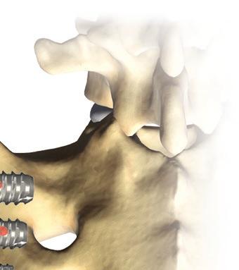
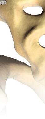
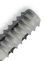
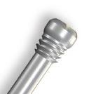
4 4 TriCor Sacroiliac Joint Fusion System Surgical Technique Guide System Overview The TriCor System allows for fusion and stabilization of the SI joint in eligible patients where appropriate non-surgical treatment has failed. The TriCor System is intended for sacroiliac joint fusion for conditions including degenerative sacroiliitis and sacroiliac joint disruptions. The device optionally incorporates a proprietary dualpitch compression-thread design and titanium plasma coating to stabilize the SI joint in fusion procedures. The design of the implant allows for bone graft to be introduced into the joint and implant in order to promote fusion. The TriCor System is a true bony fusion and arthrodesis system. The implant and instrumentation suite allows for direct exposure and preparation of the SI joint surface, placement of bone graft into the SI joint space under direct visualization and placement of bone graft directly within the TriCor implant itself. Fluoroscopic Outlet View showing TriCor implant positioning


5 TriCor Sacroiliac Joint Fusion System Surgical Technique Guide 5 Anatomy Overview Structural Anatomy Sacroiliac Joint Bicondylar synovial joint Joins the sacrum to the pelvis Weight-bearing, shock absorber Kidney-bean shape Strengthens ligamentous support and irregular articular surfaces help to resist shear forces Ilium SI Joint Ilium SI Joint Sacrum Sacral Canal Articular Process Ala Vertebral Body Ala SI Joint

 Ala (2 lines")

 1 SI Joint 2")


6 6 TriCor Sacroiliac Joint Fusion System Surgical Technique Guide Imaging Techniques Lateral View Posterior Sacral Wall (PSW) Ala (2 lines superimposed) Anterior Sacral Wall Inferior Endplate L Superior Endplate S1 6 Greater Sciatic Notch Inlet View (20 25 Caudally) 1 SI Joint 2 S1 Foramen 3 S2 Foramen 4 L5 Nerve 5 Pelvic Brim Outlet View (40 60 Cephalad) 1 SI Joint 2 Superior Alar Surface 3 Inferior Endplate of L5 4 Superior Endplate of S S1 Foramen S2 Foramen 6


7 TriCor Sacroiliac Joint Fusion System Surgical Technique Guide 7 Patient Preparation Posterior Sacral Wall Sacral Notch SI Joint Sacral Canal S1 Foramen Anterior Sacral Wall Ala Greater Sciatic Notch Superior Endplate S1 Inferior Endplate L5 S2 Foramen L5 Nerve SI Joint Inferior Endplate L5 Superior Endplate S1


8 8 TriCor Sacroiliac Joint Fusion System Surgical Technique Guide Intraoperative Imaging Lateral View In order to obtain a true lateral view, align the alae so they are superimposed over one another. Inlet View Tilt the C-Arm until a clear, strong pelvic brim is seen; the anterior wall of the sacrum will appear as one line. Outlet View The SI joint, ilium, sacrum and sacral foramen will be visible. Pre-Op Planning Operating Room Setup Patient positioned in a prone position Jackson or flat table preferably C-Arm positioned on non-operative side


9 TriCor Sacroiliac Joint Fusion System Surgical Technique Guide 9 Open Surgical Technique Posterior Skin Incision Lateral Skin Marking and Incision 1 2 Fig. 1 Step 1 Make an incision along the posterior two-thirds of the iliac crest following the posterior superior iliac spine. Use preferred retraction method to access and visualize the symptomatic SI joint. Cut into the ilium and remove a block of bone, as well as any necessary cartilage. Once the cartilage removal is complete, place the bone back so it contacts the sacral bone. Make sure the block is secure in order to prepare the SI joint for bony arthrodesis. (Fig. 1) NOTE: The Right Angle Curette or any other preferred medical instruments may be used to decorticate, remove cartilage and prepare the SI joint for bony arthrodesis. Fig. 2 Step 2 Use the Exchange Pin to mark the Posterior Sacral Wall (PSW, #1) and Sacral Alar Line (#2) with a marking pen. Make a skin incision along the Posterior Sacral Wall, approximately 3 5cm in length, starting at intersection with sacral ala skin marking. Beginning in the Lateral View, take the Trocar Steinmann Pin and insert the Steinmann Pin through the skin incision approximately 1cm anterior to the Posterior Sacral Wall and 1cm inferior to the ala. (Fig. 2) NOTE: Use the #1 Tissue Shield to stabilize the Trocar Steinmann Pin for impaction. Trocar Steinmann Pin (Z ) #1 Tissue Shield (X )
10 10 TriCor Sacroiliac Joint Fusion System Surgical Technique Guide Steinmann Pin Placement Fig. 3a Fig. 3b Fig. 3c Step 3 Confirm placement in three views: LATERAL VIEW Place the Trocar Steinmann Pin approximately 1cm anterior to the PSW and 1cm inferior to the ala. (Fig. 3a) INLET VIEW The angle of the Trocar Steinmann Pin should be heading towards the middle of the sacrum. (Fig. 3b) OUTLET VIEW The Trocar Steinmann Pin should be parallel to S1 endplate. Mallet the Steinmann Pin in final desired depth in Outlet View. (Fig. 3c) NOTE: Blunt or Threaded Steinmann Pins are available to replace the Trocar Steinmann Pin after placement, if desired. Mallet (X )
11 TriCor Sacroiliac Joint Fusion System Surgical Technique Guide 11 Measure Drill Assembly Drill Fig. 4 Step 4 Position #2 or #3 Tissue Shield over the Steinmann Pin. While keeping the Tissue Shield in place, use the Steinmann Pin Depth Gage/Guide to select the appropriate implant. Insert the Steinmann Pin Depth Gage/Guide underneath the inserted Steinmann Pin and dock onto the proximal end of the Tissue Shield. Measure with the #3 Tissue Shield for 12.5mm implants and measure with #2 Tissue Shield for 7mm implants. Remove the Tissue Shield. (Fig. 4) NOTE: Utilize the correct side of the Steinmann Pin Depth Gage/Guide; it is indicated for #2 and #3 Tissue Shields. Fig. 5 Step 5 Attach the drill bit to the Ratcheting T-Handle or cordless power drill using the provided Jacobs Chuck. (Fig. 5) NOTE: Make sure the flat portion of the Jacobs Chuck attachment fits flush to the walls if using a cordless power drill. NOTE: The Drill flutes are designed to capture the autogenous bone graft for reuse in the 12.5mm anchor implant. Fig. 6 Step 6 Place the Drill over the Steinmann Pin, slowly advancing until the ilium is reached. Make sure the drill is co-linear with the pin to avoid binding on the pin. Using the Outlet View, confirm accurate placement of the Drill over the Steinmann Pin. Under fluoroscopic guidance, continue to advance the Drill just across the sacroiliac joint, through the sacral cortex. Try to preserve the sacral bone for re-packing the implant. (Fig. 6) NOTE: Once the Drill reaches the SI joint, exercise caution advancing into the sacrum. NOTE: Once the Drill has reached the desired depth as indicated by the markings on the shaft, place the Exchange Pin down the cannulated portion of the driver until it reaches the proximal tip of the Steinmann Pin. Slowly remove the Drill while keeping pressure on the Exchange Pin to ensure the Steinmann Pin remains in place. Steinmann Pin Depth Gage/Guide (X ) Drills, Cannulated mm (X ) mm (X ) Ratcheting T-Handle (N ) Jacobs Chuck Adaptor (N ) Tissue Shields #2 (X ) #3 (X ) Exchange Pin (X )
 NOTE: Do not tap under power. Fig. 8 Step 8 Place the Tap over the Steinmann Pin, slowly advancing until you reach the ilium.")

12 12 TriCor Sacroiliac Joint Fusion System Surgical Technique Guide Tap Assembly Tap Decortication and Sacroiliac Joint Visualization Fig. 7 Step 7 Attach the Tap to the Ratcheting T-Handle. (Fig. 7) NOTE: Do not tap under power. Fig. 8 Step 8 Place the Tap over the Steinmann Pin, slowly advancing until you reach the ilium. Make sure the Tap is collinear with the pin to avoid binding on the pin. Using the Outlet View, confirm placement. Under fluoroscopic guidance, continue to advance the Tap across the sacroiliac joint, through to the sacral cortex. Try to preserve sacral bone for re-packing into the implant. (Fig. 8) NOTE: Once the Tap reaches the SI joint, exercise caution advancing into the sacrum. NOTE: Once the Tap has reached the desired depth as indicated by the markings on the shaft, place the Exchange Pin down the cannulated portion of the driver until it reaches the proximal tip of the Steinmann Pin. Slowly remove the Tap while keeping pressure on the Exchange Pin to ensure the Steinmann Pin remains in place. Fig. 9 Step 9 Take the Right Angle Curette and follow along the Steinmann Pin down to the SI joint. Once a tactile feel has been achieved, confirm in the Outlet View to verify placement in the joint. Rotate the instrument to prepare the SI joint space for bony arthrodesis. Remove the instrument once the site has been properly prepared. (Fig. 9) NOTE: A standard 2mm scope may be used through the #3 Tissue Shield for additional SI joint visualization. Right Angle Curette (X ) Tap, Cannulated mm (X ) mm (X )

13 TriCor Sacroiliac Joint Fusion System Surgical Technique Guide 13 Bone Graft Pre-Pack (12.5mm Implant Only) Fig. 10 Fig. 11 Step 10 Use the Graft Packing Block to pre-pack selected implant with preferred bone grafting choice. Place the distal tip of the implant on the block and insert the bone graft into the implant through the proximal end. (Fig. 10) CAUTION: Do not over pack, as implant will obtain patient autograft during implantation. Step 11 Select the Implant Screwdriver and place onto the Ratcheting T-Handle. Select the corresponding implant and place onto the distal tip of the driver, making sure the implant is fully seated with the driver shaft. Insert the distal end of the implant over the Steinmann Pin and advance the implant, under fluoroscopy, to desired depth. (Fig. 11) TriCor System Bone Graft Volumes (Approximate) 12.5mm implants LENGTH 30mm 35mm 40mm 45mm 50mm 55mm 60mm 65mm 70mm VOLUME 1.50cc 1.70cc 2.00cc 2.20cc 2.50cc 2.70cc 3.10cc 3.30cc 3.50cc 12.5mm Graft Packing Block (X ) 12.5mm Implant Screwdriver (X )
 OUTLET VIEW Implant progression. (Fig. 12b) OUTLET VIEW Implant progression.")
14 14 TriCor Sacroiliac Joint Fusion System Surgical Technique Guide Implant Loading and Final Placement Fig. 12a Fig. 12b Fig. 12c Step 12 OUTLET VIEW Implant progression. Initial placement. (Fig. 12a) OUTLET VIEW Implant progression. (Fig. 12b) OUTLET VIEW Implant progression. Fully seated. (Fig. 12c)
15 TriCor Sacroiliac Joint Fusion System Surgical Technique Guide 15 Steinmann Pin Depth Gage Bone Graft Post Fill (12.5mm Implant Only) Fig. 13 Step 13 Using the first Steinmann Pin, insert the fixed portion of the Steinmann Pin Depth Gage/ Guide over the already inserted pin. Under fluoroscopy in the Lateral View, insert the second pin following the curve of the sacrum. Confirm in the three views (Lateral, Inlet, Outlet) that the second Steinmann Pin placement is accurate. Repeat steps above for implant insertion of the subsequent implants. (Fig. 13) Fig. 14 Step 14 After the Second Steinmann Pin placement is confirmed, insert the Bone Graft Funnel over the Steinmann Pin from the first implant. Rotate the funnel until fully engaged with the implant. Remove the Steinmann Pin from the first implant once the Bone Graft Funnel is in place. Next, insert the preferred bone graft through the Bone Graft Funnel, following with the Graft Tamp until fully seated with the implant. (Fig. 14) Steinmann Pin Depth Gage/Guide (X ) Trocar Steinmann Pin (Z ) 12.5mm Graft Funnel (X ) Graft Tamp (X )


 OUTLET VIEW (Fig. 15c) LATERAL VIEW (Fig.")

16 16 TriCor Sacroiliac Joint Fusion System Surgical Technique Guide Second Implant Targeting Fig. 15a Fig. 15b Fig. 15c Step 15 Repeat Step 3 for placement of the second Trocar Steinmann Pin. INLET VIEW (Fig. 15b) OUTLET VIEW (Fig. 15c) LATERAL VIEW (Fig. 15a) Second Implant Insertion Fig. 16a Fig. 16b Fig. 16c Step 16 Repeat Steps LATERAL VIEW (Fig. 16a) INLET VIEW (Fig. 16b) OUTLET VIEW (Fig. 16c)

 INLET VIEW (Fig. 17b) OUTLET VIEW (Fig.")

17 TriCor Sacroiliac Joint Fusion System Surgical Technique Guide 17 Third Implant Targeting Fig. 17a Fig. 17b Fig. 17c Step 17 Repeat Step 3 for targeting of the third implant. LATERAL VIEW (Fig. 17a) INLET VIEW (Fig. 17b) OUTLET VIEW (Fig. 17c) Third Implant Insertion Fig. 18a Fig. 18b Fig. 18c Step 18 Repeat Steps LATERAL VIEW (Fig. 18a) INLET VIEW (Fig. 18b) OUTLET VIEW (Fig. 18c)
18 18 TriCor Sacroiliac Joint Fusion System Surgical Technique Guide Final Implant Construct Fig. 19a Fig. 19b Fig. 19c Step 19 Confirm final implant placement using Lateral, Inlet and Outlet Views under fluoroscopy. INLET VIEW (Fig. 19b) OUTLET VIEW (Fig. 19c) LATERAL VIEW (Fig. 19a)


 Step 2 Make a skin incision along the Posterior")


19 TriCor Sacroiliac Joint Fusion System Surgical Technique Guide 19 Tissue Shield Surgical Technique Skin Marking Skin Incision 1 2 Fig. 20 Step 1 Use the Exchange Pin to mark the Posterior Sacral Wall (PSW, #1) and Sacral Alar Line (#2) with a marking pen. (Fig. 20) Step 2 Make a skin incision along the Posterior Sacral Wall, approximately 3 5cm in length, starting at intersection with sacral ala skin marking. Beginning in the Lateral View, insert the Trocar Steinmann Pin through skin incision approximately 1cm anterior to the Posterior Sacral Wall and 1cm inferior to the ala. (Fig. 20) Exchange Pin (X )

20 20 TriCor Sacroiliac Joint Fusion System Surgical Technique Guide Steinmann Pin Placement Fig. 21a Fig. 21b Fig. 21c Step 3 Confirm placement in three views: LATERAL VIEW Place Steinmann Pin approximately 1cm anterior to PSW and 1cm inferior to ala. (Fig. 21a) NOTE: Use the #1 Tissue Shield to stabilize the Trocar Steinmann Pin for impaction. INLET VIEW The angle of Steinmann Pin should be heading towards the middle of the sacrum. (Fig. 21b) OUTLET VIEW The Steinmann Pin should be parallel to the S1 endplate. Mallet the Steinmann Pin to final desired depth in Outlet View. (Fig. 21c) NOTE: Blunt or Threaded Steinmann Pins are available to replace the Trocar Steinmann Pin after placement, if desired. Steinmann Pins Trocar (Z ) Threaded (Z ) Blunt (Z ) Mallet (X ) #1 Tissue Shield (X )
21 TriCor Sacroiliac Joint Fusion System Surgical Technique Guide 21 Tissue Shield Placement Measuring/Implant Selection Fig. 22 Step 4 Drop #1, #2 and #3 Tissue Shields, in sequence, over the Steinmann Pin. Once the #3 Tissue Shield is in place, remove the #1 and #2 Tissue Shields. (Fig. 22) NOTE: Optional Tissue Shield Guide Handle may be used for added stability. Fig. 23 Step 5 While keeping the Tissue Shield in place, use the Steinmann Pin Depth Gage/Guide to select appropriate implant. Insert the Steinmann Pin Depth Gage underneath the inserted Steinmann Pin and dock onto the proximal end of the Tissue Shield. Measure with #3 Tissue Shield for 12.5mm implants and measure with #2 Tissue Shield for 7mm implants. (Fig. 23) NOTE: Utilize the correct side of the Steinmann Pin Depth Gage/Guide; it is indicated for #2 and #3 Tissue Shields. Tissue Shields #1 (X ) #2 (X ) #3 (X ) Tissue Shield Guide Handle (X ) Steinmann Pin Depth Gage/Guide (X )
22 22 TriCor Sacroiliac Joint Fusion System Surgical Technique Guide Drill Assembly Drill Tap Assembly Fig. 24 Step 6 Attach the Drill to the Ratcheting T-Handle or cordless power drill using the provided Jacobs Chuck. (Fig. 24) NOTE: Make sure the flat portion of the provided Jacobs Chuck attachment fits flush to the walls if using the cordless power drill. NOTE: The Drill flutes are designed to capture the autogenous bone graft for reuse in the 12.5mm anchor implant. Fig. 25 Step 7 Place the Drill over the Steinmann Pin slowly advancing until the ilium is reached. Make sure that the Drill is collinear with the Pin to avoid binding on the Pin. Using the Outlet View, confirm accurate placement of the Drill over the Steinmann Pin. Under fluoroscopic guidance, continue to advance the Drill just across the sacroiliac joint, through the sacral cortex. Try to preserve sacral bone for re-packing the implant. (Fig. 25) NOTE: Once the Drill has reached the desired depth as indicated by the markings on the shaft, place the Exchange Pin down the cannulated portion of the driver until it reaches the proximal tip of the Steinmann Pin. Slowly remove the Drill while keeping pressure on the Exchange Pin to ensure that the Steinmann Pin remains in place. NOTE: Once the Drill reaches the SI joint, exercise caution advancing into the sacrum. Fig. 26 Step 8 Attach the Tap to the Ratcheting T-Handle. (Fig. 26) CAUTION: Do not tap under power. Drills, Cannulated mm (X ) Ratcheting T-Handle (N ) Jacobs Chuck Adaptor (N ) Exchange Pin (X ) Tap, Cannulated mm (X ) mm (X ) mm (X )

 NOTE: Once the Tap reaches the SI joint, exercise caution advancing into the sacrum.")
23 TriCor Sacroiliac Joint Fusion System Surgical Technique Guide 23 Tap Decortication and Sacroiliac Joint Visualization Bone Graft Pre-Pack (12.5mm Implant Only) Fig. 27 Fig. 28 Fig. 29 Step 9 Place the Tap over Steinmann Pin, slowly advancing until you reach the ilium. Make sure that the Tap is collinear with the pin to avoid binding on the pin. Using the Outlet View, confirm placement. Under fluoroscopic guidance, continue to advance the Tap across the sacroiliac joint, through to the sacral cortex. Try to preserve sacral bone for re-packing into the implant. (Fig. 27) NOTE: Once the Tap reaches the SI joint, exercise caution advancing into the sacrum. NOTE: Once the Tap has reached the desired depth as indicated by the markings on the shaft, place the Exchange Pin down the cannulated portion of the driver until it reaches the proximal tip of the Steinmann Pin. Slowly remove the Tap while keeping pressure on the Exchange Pin to ensure that the Steinmann Pin remains in place. Step 10 Take the Right Angle Curette and place through the #3 Tissue Shield. Once a tactile feel has been achieved, confirm in the Outlet View to verify placement in the joint. Rotate the instrument to prepare the SI joint space for bony arthrodesis. Remove the instrument once the site has been properly prepared. (Fig. 28) NOTE: A standard 2mm scope may be used through the #3 Tissue Shield for additional SI joint visualization. Step 11 Use the Graft Packing Block to pre-pack selected implant with preferred bone grafting choice. Place the distal tip of the implant on the block and insert the bone graft into the implant through the proximal end. (Fig. 29) CAUTION: Do not over pack as implant will obtain patient autograft during implantation. TriCor System Bone Graft Volumes (Approximate) 12.5mm implants LENGTH VOLUME 30mm 1.50cc 35mm 1.70cc 40mm 2.00cc 45mm 2.20cc 50mm 2.50cc 55mm 2.70cc 60mm 3.10cc 65mm 3.30cc 70mm 3.50cc Right Angle Curette (X ) 12.5mm Graft Packing Block (X )

 Fig.")


24 24 TriCor Sacroiliac Joint Fusion System Surgical Technique Guide Implant Loading and Final Placement Steinmann Pin Depth Gage Fig. 30 Step 12 Select the Implant Screwdriver and place onto the Ratcheting T-Handle. Select the corresponding implant and place onto the distal tip of the driver, making sure the implant is fully seated with the driver shaft. Insert the distal end of the implant over the Steinmann Pin and advance the implant, under fluoroscopy, to desired depth. (Fig. 30) Fig. 31 Step 13 Using the first Steinmann Pin, insert the Steinmann Pin Depth Gage/Guide starting in the 0 position over the already inserted pin. Under fluoroscopy in the Lateral View, insert the second pin at the 20 marker while following the curve of the sacrum. Confirm in the three views (Lateral, Inlet, Outlet) that the second Steinmann Pin placement is accurate. Repeat steps above for implant insertion of the subsequent implants. (Fig. 31) Repeat steps on pages using the Tissue Shield for the remaining two implants. Steinmann Pin Depth Gage/Guide (X ) Implant Screwdriver mm (X ) mm (X )
25 TriCor Sacroiliac Joint Fusion System Surgical Technique Guide 25 Bone Graft Post Fill (12.5mm Implant Only) Fig. 32 Step 14 After the Second Steinmann Pin placement is confirmed, insert the Graft Funnel through the #3 Tissue Shield and over the Steinmann Pin from the first implant. Rotate the Graft Funnel until fully engaged with the implant. Remove the Steinmann Pin from the first implant once the Graft Funnel is in place. Next, insert the preferred bone graft through the Graft Funnel, following with the Graft Tamp until fully seated with the implant. (Fig. 32) Step 15 Repeat steps 4 14 on pages of the Tissue Shield Technique for the remaining two implants. Refer to pages for images showing implant placement. 12.5mm Graft Funnel (X ) Graft Tamp (X )
26 26 TriCor Sacroiliac Joint Fusion System Surgical Technique Guide Implant Removal and Adjustment Surgical Technique Implant Removal and Adjustment Fig. 33 After the Second Steinmann Pin placement: OPTION #1 12.5mm IMPLANT Attach the Ratcheting T-Handle to the 12.5mm Implant Screwdriver, and locate the proximal end of the implant that needs adjusting. Fully seat the distal end of the Implant Screwdriver into the desired implant. With the Ratcheting T-Handle, rotate counterclockwise to adjust or fully remove the implant. (Fig. 33) OPTION #2 12.5mm IMPLANT Using palpation and fluoroscopy, locate the proximal end of the implant that needs adjusting. Insert the distal end of the 12.5mm Implant Removal Instrument into the desired implant until the initial fenestration is reached. Rotate the implant removal tool counterclockwise or pull axially to adjust or fully remove the implant. NOTE: The knob at the proximal end of the 12.5mm Implant Removal Tool must be pulled proximally during insertion into the implant. Next, upon finding the fenestration, the knob is pushed forward and locked to retain the implant. 7mm ANCHOR IMPLANT Attach the Ratcheting T-Handle to the 7mm Adjustment Screwdriver, and locate the proximal end of the implant that needs adjusting. Fully seat the distal end of the Implant Screwdriver into the desired implant. With the Ratcheting T-Handle, rotate counterclockwise to adjust or fully remove the implant. 12.5mm Implant Screwdriver (X ) 7mm Adjustment Screwdriver (X ) Ratcheting T-Handle (N ) 12.5mm Implant Removal Instrument (X )
27 TriCor Sacroiliac Joint Fusion System Surgical Technique Guide 27 Instrument Visual Guide Ratcheting T-Handle (N ) Jacobs Chuck Adaptor (N ) #1 Tissue Shield, Stainless Steel, 9mm (X ) #2 Tissue Shield, Stainless Steel, 13mm (X ) #3 Tissue Shield, Stainless Steel, 16mm (X ) Tissue Shield Guide Handle (X ) Implant Screwdrivers, Cannulated mm (X ) mm (X ) Drills, Cannulated mm (X ) mm (X ) Taps, Cannulated mm (X ) mm (X ) Bone Awl, Cannulated (X ) 12.5mm Graft Packing Block (X ) Mallet (X )
28 28 TriCor Sacroiliac Joint Fusion System Surgical Technique Guide 12.5mm Graft Funnel (X ) Graft Tamp (X ) Steinmann Pin Depth Gage/Guide (X ) Right Angle Curette (X ) 12.5mm Implant Removal Instrument (X ) 7mm Adjustment Screwdriver (X ) Cannula Cleaner (X ) Steinmann Pin Trocar (Z ) Threaded (Z ) Blunt (Z ) Exchange Pin (X )
29 TriCor Sacroiliac Joint Fusion System Surgical Technique Guide 29 Kit Contents TriCor Sacroiliac Joint Fusion Instrument and Implant System Kit Number: Implants Part Number Description Quantity Cannulated Screw, Dual Thread, ø7mm 30mm Cannulated Screw, Dual Thread, ø7mm 35mm Cannulated Screw, Dual Thread, ø7mm 40mm Cannulated Screw, Dual Thread, ø7mm 45mm Cannulated Screw, Dual Thread, ø7mm 50mm Cannulated Screw, Dual Thread, ø7mm 55mm Cannulated Screw, Dual Thread, ø7mm 60mm Cannulated Screw, Dual Thread, ø7mm 65mm Cannulated Screw, Dual Thread, ø7mm 70mm Washer, 13mm Cannulated Screw, Dual Thread, Plasma Coated, ø12.5mm 30mm Cannulated Screw, Dual Thread, Plasma Coated, ø12.5mm 35mm Cannulated Screw, Dual Thread, Plasma Coated, ø12.5mm 40mm Cannulated Screw, Dual Thread, Plasma Coated, ø12.5mm 45mm Cannulated Screw, Dual Thread, Plasma Coated, ø12.5mm 50mm Cannulated Screw, Dual Thread, Plasma Coated, ø12.5mm 55mm Cannulated Screw, Dual Thread, Plasma Coated, ø12.5mm 60mm Cannulated Screw, Dual Thread, Plasma Coated, ø12.5mm 65mm Cannulated Screw, Dual Thread, Plasma Coated, ø12.5mm 70mm 2 Part Number Description Quantity Part Number Description Quantity Steinmann Pin Depth Gage/Guide #2 Tissue Shield, Stainless Steel, 13mm Graft Tamp #3 Tissue Shield, Stainless Steel, 16mm Graft Packing Block, 12.5mm Mallet Sterilization Case Right Angle Curette Steinmann Pin Holder (Trocar) ø12.5mm Implant Screwdriver, Cannulated Steinmann Pin Holder (Threaded) ø12.5mm Drill, Cannulated Instructions for Use ø12.5mm Tap, Cannulated ø7mm Implant Screwdriver, Cannulated Steinmann Pin Holder (Blunt) ø7mm Adjustment Screwdriver, Cannulated ø12.5mm Graft Funnel ø7mm Drill, Cannulated Tissue Shield Guide Handle ø7mm Tap, Cannulated Ratcheting T-Handle, 1/4" Drive Bone Awl, Cannulated Jacobs Chuck Adaptor, 1/4" Square mm Stylet (.090"), Cannula Cleaner ø12.5mm Implant Removal Instrument #1 Tissue Shield, Stainless Steel, 9mm 1 Single-Use Part Number Description Quantity ø2.4mm 300mm (.094") Steinmann Pin (Trocar) ø2.4mm 300mm (.094") Steinmann Pin (Threaded) ø2.4mm 300mm (.094") Steinmann Pin (Blunt) mm Exchange Pin 2
30 30 TriCor Sacroiliac Joint Fusion System Surgical Technique Guide Important Information on the TriCor Sacroiliac Joint Fusion System DEVICE DESCRIPTION The TriCor System consists of different diameter implants in various lengths and thread configurations to accommodate variations in patient anatomy. The TriCor System is manufactured from titanium alloy in accordance with ASTM F136, as well as an optional version where exterior surfaces are coated with medicalgrade commercially pure titanium (CP Ti) per ASTM F1580. All implants are intended as single use only and should not be reused under any circumstances. Note: 12.5mm anchor implants are plasmacoated, 7mm locking implants are not coated. INDICATIONS The TriCor Sacroiliac Joint Fusion System is intended for sacroiliac joint fusion for conditions including degenerative sacroiliitis and sacroiliac joint disruptions. CONTRAINDICATIONS Contraindications for the TriCor Joint Fusion System are similar to those of other systems of similar design, and include, but are not limited to: 1. Patients with probable intolerance to the materials used in the manufacture of this device. 2. Patients with infection, inflammation, fever, tumors, elevated white blood count, obesity, pregnancy, mental illness and other medical conditions which would prohibit beneficial surgical outcome. 3. Patients resistant to following post-operative restrictions on movement, especially in athletic and occupational activities. 4. Use with components from other systems. 5. Grossly distorted anatomy caused by congenital abnormalities. 6. Any other medical or surgical condition which would preclude the potential benefit of spinal implant surgery. 7. Rapid joint disease, bone absorption, osteopenia. Osteoporosis is a relative contraindication since this condition may limit the degree of obtainable correction, stabilization, and/or the amount of mechanical fixation. 8. Any case where the implant components selected for use would be too large or too small to achieve a successful result. 9. Any patient having inadequate tissue coverage over the operative site or inadequate bone stock or quality. 10. Any patient in which implant utilization would interfere with anatomical structures or expected physiological performance. 11. Any case not described in the indications for use. 12. Reuse or multiple uses. WARNINGS AND PRECAUTIONS As with any surgical system, the TriCor Sacroiliac Joint Fusion system should be used by experienced surgeons with specific training in the use of the spinal system because this is a technically demanding procedure presenting a risk of serious injury to the patient. Knowledge of surgical techniques, proper reduction, selection and placement of implants, and pre- and post-operative patient management are considerations essential to a successful surgical outcome. Appropriate selection, placement and fixation of the spinal system components are critical factors which affect implant service life. As in the case of all prosthetic implants, the durability of these components is affected by numerous biologic, biomechanics and other extrinsic factors, which limit their service life. Accordingly, strict adherence to the indications, contraindications, precautions, and warnings for this product is essential to potentially maximize service life. (Note: While proper implant selection can minimize risks, the size and shape of human bones present limitations on the size, shape, and strength of the implants). Patients who smoke have been shown to have an increased incidence of pseudoarthrosis. Such patients should be advised of this fact and warned of the potential consequences. Patients with previous spinal surgery at the level to be treated may have different clinical outcomes compared to those without a previous surgery. Based on the fatigue testing results, the physician/ surgeon should consider the level of implantation, patient weight, patient activity level, and other patient conditions, etc. which may have an impact on the performance of the system. If the patient is involved in an occupation or activity which applies inordinate stress upon the implant (e.g. substantial walking, running, lifting, or muscle strain) resultant forces can cause failure of the device. In some cases, progression of degenerative disease may be so advanced at the time of implantation that the expected useful life of the appliance may be substantially decreased. In such cases, orthopedic devices may be considered only as a delaying technique or to provide temporary relief. Patients should be instructed in detail about the limitations of the implants, including, but not limited to, the impact of excessive loading through patient weight or activity, and be taught to govern their activities accordingly. The patient should understand that a metallic implant is not as strong as normal, healthy bone and will bend, loosen or fracture if excessive demands are placed on it. An active, debilitated, or demented patient who cannot properly use weight supporting devices may be particularly at risk during postoperative rehabilitation. Care must be taken to protect the components from being marred, nicked or notched as a result of contact with metal or abrasive objects. Alterations will produce defects in surface finish and internal stresses which may become the focal point for eventual breakage of the implant. As with all orthopedic and neurosurgical implants, none of the TriCor System components should ever be reused under any circumstances. Risks associated with reuse include infection, non-union (pseudarthrosis), serious patient injury or death. Due to the presence of implants, interference with roentgenographic, CT and/or MR imaging may result. The TriCor System has not been evaluated for safety and compatibility in the MR environment. The TriCor System has not been tested for heating or migration in the MR environment. It must be noted that there are several different manufacturers and generations of MRI systems available, and Zimmer Biomet Spine cannot make any claims regarding the safety of Zimmer Biomet Spine implants and devices with any specific MR system. Physician Note: The physician is the learned intermediary between the company and the patient. The indications, contraindications, warnings, and precautions given in this document must be conveyed to the patient.
31 TriCor Sacroiliac Joint Fusion System Surgical Technique Guide 31
32 Disclaimer: This document is intended exclusively for physicians and is not intended for laypersons. Information on the products and procedures contained in this document is of a general nature and does not represent and does not constitute medical advice or recommendations. Because this information does not purport to constitute any diagnostic or therapeutic statement with regard to any individual medical case, each patient must be examined and advised individually, and this document does not replace the need for such examination and/or advice in whole or in part. Caution: Federal (USA) law restricts this device to sale by or on the order of a physician. Rx Only. Please refer to the package inserts for important product information, including, but not limited to, indications, contraindications, warnings, precautions, adverse effects and patient counseling information. Manufactured by: X-spine Systems, Inc. 452 Alexandersville Road Miamisburg, OH Distributed by: Zimmer Biomet Spine, Inc Westmoor Dr. Westminster, CO USA EMERGO EUROPE Prinsessegracht AP, The Hague The Netherlands zimmerbiomet.com 2017 Zimmer Biomet Spine, Inc. All rights reserved. All content herein is protected by copyright, trademarks and other intellectual property rights owned by or licensed to Zimmer Biomet Spine, Inc. or one of its affiliates unless otherwise indicated, and must not be redistributed, duplicated or disclosed, in whole or in part, without the express written consent of Zimmer Biomet Spine. This material is intended for health care professionals, the Zimmer Biomet sales force and authorized representatives. Distribution to any other recipient is prohibited GLBL-en-REV0417
Surgical Technique Guide
 Sacroiliac Joint Fusion System Surgical Technique Guide Moving Life Forward Table of Contents SiCure Implant Overview...2 SiCure System Information...3 X-ray Basics...4 Patient Positioning....5 Surgical
Zimmer Facet Screw System Surgical Technique
 Zimmer Facet Screw System Surgical Technique 2 Zimmer Facet Screw System Surgical Technique Zimmer Facet Screw System Surgical Technique Description, Indications & Contraindications...3 Surgical Technique...4
Veyron -C Anterior Cervical System Surgical Technique
 Veyron -C Anterior Cervical System Surgical Technique 2 Veyron-C Anterior Cervical System Surgical Technique Veyron-C Anterior Cervical System Surgical Technique Description, Indications & Contraindications...3
Zimmer Anterior Buttress Plate System. Surgical Technique
 Zimmer Anterior Buttress Plate System Surgical Technique 2 Zimmer Anterior Buttress Plate System Surgical Technique Zimmer Anterior Buttress Plate System Surgical Technique Description, Indications & Contraindications...
TM TM Surgical Technique
 TM TM Surgical Technique TABLE OF CONTENTS Reli SP Spinous Plating System Overview Device Description Implant Features Indications Instruments Access Instruments Preparation Instruments Insertion Instruments
nvt Transforaminal Lumbar Interbody Fusion System
 nvt Transforaminal Lumbar Interbody Fusion System 1 IMPORTANT INFORMATION FOR PHYSICIANS, SURGEONS, AND/OR STAFF The nv a, nv p, and nv t are an intervertebral body fusion device used in the lumbar spine
nvp Posterior Lumbar Interbody Fusion System
 nvp Posterior Lumbar Interbody Fusion System 1 IMPORTANT INFORMATION FOR PHYSICIANS, SURGEONS, AND/OR STAFF The nv a, nv p, and nv t are an intervertebral body fusion device used in the lumbar spine following
nva Anterior Lumbar Interbody Fusion System
 nva Anterior Lumbar Interbody Fusion System 1 IMPORTANT INFORMATION FOR PHYSICIANS, SURGEONS, AND/OR STAFF The nv a, nv p, and nv t are an intervertebral body fusion device used in the lumbar spine following
Single-Thread Screw Available in 25-45mm lengths (5mm Increments) Dual-Thread Screw Available in 30-45mm lengths (5mm Increments)
 Dual-Thread Screw Available in 30-45mm lengths (5mm Increments)") Single-Thread Screw Available in 25-45mm lengths (5mm Increments) Dual-Thread Screw Available in 30-45mm lengths (5mm Increments) 4.5mm diameter screws All screws cannulated 12mm percutaneous incision
Single-Thread Screw Available in 25-45mm lengths (5mm Increments) Dual-Thread Screw Available in 30-45mm lengths (5mm Increments) 4.5mm diameter screws All screws cannulated 12mm percutaneous incision
EXACTECH SPINE. Operative Technique. Cervical Spacer System. Surgeon focused. Patient driven. TM
 EXACTECH SPINE Operative Technique Cervical Spacer System Surgeon focused. Patient driven. TM ACAPELLA ONE Acapella One Cervical Spacer System is an anterior cervical discectomy and fusion device with
Table of Contents.
 surgical technique The Ambassador TM Anterior Cervical Plate System is a versatile system of implants and instruments with a variety of sizes to provide optimal anatomic compatibility. The integrated cam
HawkeyeTM Peek. surgical technique
 HawkeyeTM Peek surgical technique Introduction The ChoiceSpine HAWKEYE Vertebral Body Replacement (VBR) System is intended for use in the thoracolumbar spine (T1 - L5) to replace a collapsed, damaged,
Cervical Spacer System surgical technique
 Blackhawk TM Cervical Spacer System surgical technique Blackhawk TM The BLACKHAWK Cervical Spacer System is designed to provide biomechanical stabilization as an adjunct to fusion. Spinal fixation should
N-Force Fixation System. Surgical Technique
 N-Force Fixation System Surgical Technique Table of Contents Features... 2 Indications/Contraindications... 3 Surgical Technique 4.0 mm...6 11 Step 1: Preoperative Radiographic Fracture Assessment and
Lapidus Arthrodesis System Instructions for Use
 Lapidus Arthrodesis System Instructions for Use Description The AlignMATE Lapidus Arthrodesis System consists of bone plates and bone screws (locking, non-locking and interfragmentary), which are intended
JuggerLoc Bone-to-Bone System for Ankle Syndesmosis Fixation. Surgical Technique
 JuggerLoc Bone-to-Bone System for Ankle Syndesmosis Fixation Surgical Technique Table of Contents Position and Preparation... 2 Incision... 2 Fracture Reduction... 2 Drill Fibula and Tibia... 3 JuggerLoc
SURGICAL TECHNIQUE GUIDE TRESTLE. Anterior Cervical Plating System
 SURGICAL TECHNIQUE GUIDE TRESTLE Anterior Cervical Plating System 2 SURGICAL TECHNIQUE GUIDE SURGICAL TECHNIQUE GUIDE System Features Large window enables visualization of graft site and end plates Screw
X-spine Systems, Inc. Silex Sacroiliac Joint Fusion System
 X-spine Systems, Inc. Silex Sacroiliac Joint Fusion System GENERAL INFORMATION The Silex Sacroiliac Joint Fusion System consists of different diameter bone screws in various lengths and thread configurations
UniLink Interspinous Fusion System UniLink 5/1 Interspinous Fusion System UniLink Graft. Surgical Technique
 UniLink Interspinous Fusion System UniLink 5/1 Interspinous Fusion System UniLink Graft Surgical Technique 2 UniLink and UniLink 5/1 Interspinous Fusion System Surgical Technique UniLink and Unlink 5/1
Correction System. Surgical Technique
 Nextra Hammertoe Correction System Surgical Technique Maximized Bone Purchase* Stable and Secure Phalanx Optimized Screw Design Adjustable Bone-to-Bone Apposition Progressive Ratchet Tightening Mechanism
TECHNICAL BROCHURE. Capture Facet Fixation System
 TECHNICAL BROCHURE Capture Facet Fixation System Table of Contents Product Overview...2 Instruments...4 Capture Facet Screw Surgical Technique Patient Preparation and Positioning...6 Guide Pin Placement...7
Alamo C. Cervical Interbody System Surgical Technique. An Alliance Partners Company
 Cervical Interbody System Surgical Technique Table of Contents Indications for Use................................1 Device Description............................... 1 Alamo C Instruments..............................
InFix. Anterior Lumbar Device. Surgical Technique Guide
 InFix Anterior Lumbar Device Surgical Technique Guide 2 InFix Anterior Lumbar Device Surgical Technique Guide InFix Anterior Lumbar System s modular design is intended to restore lordosis, disc height
The AperFix II System
 The AperFix II System A Complete Anatomic Solution Transtibial Surgical Technique 2 AperFix II System Transtibial Surgical Technique Figure 1 A Complete Anatomic Solution The Cayenne Medical AperFix and
ACP. Anterior Cervical Plate System SURGICAL TECHNIQUE
 ACP Anterior Cervical Plate System SURGICAL TECHNIQUE ACP TABLE OF CONTENTS INTRODUCTION 4 INDICATIONS AND CONTRAINDICATIONS 5 WARNINGS AND PRECAUTIONS 6 IMPLANT DESCRIPTION 7 INSTRUMENTS 10 SURGICAL
Pinit Plate Small Bone Fusion System Bone Plate & Screw System
 Pinit Plate Small Bone Fusion System Bone Plate & Screw System Description The Pinit Plate Small Bone Fusion System consists of 2-hole bone plates made available in three length options and two thickness
Alamo T Transforaminal Lumbar Interbody System Surgical Technique
 Transforaminal Lumbar Interbody System Surgical Technique Table of Contents Indications and Device Description.............. 1 Alamo T Implant Features and Instruments...........2 Surgical Technique......................
Technique Guide Small Bone Fusion System
 Technique Guide Small Bone Fusion System The Pinit Plate Small Bone Fusion System is a super low profile, modular bone plate and screw system designed to stabilize a bunionectomy with a medial to lateral
Correction System. Surgical Technique
 Re+Line Bunion Correction System Surgical Technique Bunion Correction System Easy insertion and medial placement accuracy using Landmark Guide technology 1 mm compression slot and fixed tines to encourage
Cervical Solutions. Trinnect. Hydrated Anterior Cervical Spacer System. Surgical Technique Guide
 Cervical Solutions Trinnect Hydrated Anterior Cervical Spacer System Surgical Technique Guide 2 Trinnect Hydrated Anterior Cervical Spacer System Surgical Technique Guide Trinnect Cervical Allograft Spacers
Threshold Pedicular Fixation System Surgical Technique
 Threshold Pedicular Fixation System Surgical Technique Table of Contents Patient Preparation and Positioning... 2 Determining Incision Location... 3 Assembling the Cannulated Awl... 4 Guide Wire Placement...
Zimmer Trabecular Metal Ankle Interpositional Spacer and Trabecular Metal Ankle Fusion Spacer
 Zimmer Trabecular Metal Ankle Interpositional Spacer and Trabecular Metal Ankle Fusion Spacer Surgical Technique 2 Zimmer Trabecular Metal Ankle Interpositional Spacer and Trabecular Metal Ankle Fusion
HydraLok. Operative Technique. Polyaxial Pedicle Screw System
 HydraLok Operative Technique Polyaxial Pedicle Screw System Table of Contents Introduction...1 OPERATIVE TECHNIQUE OVERVIEW...2 DETAILED OPERATIVE TECHNIQUE...4 LOCATE AND PREPARE THE PEDICLE...4 PROBE
OPERATIVE TECHNIQUE. CONSTRUX Mini PTC. Mini PTC Spacer System
 OPERATIVE TECHNIQUE CONSTRUX Mini PTC Mini PTC Spacer System TABLE OF CONTENTS Introduction 1 Operative Technique 2 Part Numbers 6 Indications For Use 7 INTRODUCTION 1 INTRODUCTION The CONSTRUX Mini PTC
Thoracolumbar Spine Locking Plate (TSLP) System. A low-profile plating system for anterior stabilization of the thoracic and lumbar spine.
 System. A low-profile plating system for anterior stabilization of the thoracic and lumbar spine.") Thoracolumbar Spine Locking Plate (TSLP) System. A low-profile plating system for anterior stabilization of the thoracic and lumbar spine. Technique Guide Instruments and implants approved by the AO Foundation
Thoracolumbar Spine Locking Plate (TSLP) System. A low-profile plating system for anterior stabilization of the thoracic and lumbar spine. Technique Guide Instruments and implants approved by the AO Foundation
Royal Oak Cervical Plate System
 Royal Oak Cervical Plate System Manufactured by Nexxt Spine, Inc. Royal Oak Cervical Plate System INTRODUCTION FEATURES AND BENEFITS Table of Contents SURGICAL TECHNIQUE Step 1. Patient Positioning Step
C-THRU Anterior Spinal System
 C-THRU Anterior Spinal System Surgical Technique Manufactured From Contents Introduction... Page 1 Design Features... Page 2 Instruments... Page 3 Surgical Technique... Page 4 Product Information... Page
X-spine Systems, Inc. Axle Interspinous Fusion System
 X-spine Systems, Inc. Axle Interspinous Fusion System GENERAL INFORMATION The Axle Interspinous Fusion System of X-spine Systems, Inc., is an internal fixation device for spinal surgery. Various sizes
Surgical Technique. CONQUEST FN Femoral Neck Fracture System
 Surgical Technique CONQUEST FN Femoral Neck Fracture System Table of Contents Introduction... 3 Indications... 3 Product Overview... 4 Surgical Technique... 5 Patient Positioning... 5 Reduce the Fracture...
Headless Compession Screw 4.5 / 6.5 SURGICAL TECHNIQUE. Titanium or Stainless Steel. Cannulated Headless Design. Multiple Thread Options.
 Headless Compession Screw SURGICAL TECHNIQUE 4.5 / 6.5 Titanium or Stainless Steel Cannulated Headless Design Multiple Thread Options Torx Driver Sterile and Non-Sterile Options Simple Instrumentation
Thoracolumbar Solutions. Zyston Curve. Interbody Spacer System. Surgical Technique Guide
 Thoracolumbar Solutions Zyston Curve Interbody Spacer System Surgical Technique Guide 2 Zyston Curve Interbody Spacer System Surgical Technique Guide The Zyston Curve Interbody System is designed to optimize
Asnis. Micro Cannulated screw system. Xpress operative technique
 Asnis Micro Cannulated screw system Xpress operative technique Asnis Micro Cannulated screw system Table of contents Indications, precautions & contraindications 3 Operative technique 4 This publication
Hinged Laminoplasty System surgical technique
 BlackbirdTM Hls Hinged Laminoplasty System surgical technique Blackbird TM Hls The ChoiceSpine Blackbird Hinged Laminoplasty System (HLS) design eliminates fitting plates through trial and error bending.
TABLE OF CONTENTS. Vault C Anterior Cervical Discectomy 2 and Fusion (ACDF) System Overview. Implants 3. Instruments 5. Surgical Technique 10
 System Overview. Implants 3. Instruments 5. Surgical Technique 10") Surgical Technique TABLE OF CONTENTS Vault C Anterior Cervical Discectomy 2 and Fusion (ACDF) System Overview Indications 2 Implants 3 Instruments 5 Surgical Technique 10 1. Preoperative planning 10 2.
Surgical Technique TABLE OF CONTENTS Vault C Anterior Cervical Discectomy 2 and Fusion (ACDF) System Overview Indications 2 Implants 3 Instruments 5 Surgical Technique 10 1. Preoperative planning 10 2.
X-spine. Product Guide. Silex Sacroiliac Joint Fusion System
 SM X-spine Product Guide Silex Sacroiliac Joint Fusion System SILEX TM CONSIDERATIONS Safe, Reproducible Lateral Access Minimal Step Technique True Arthrodesis of the Sacroiliac Joint (SI Joint) 1 Index
OPERATIVE TECHNIQUE. anterior cervical plating system
 OPERATIVE TECHNIQUE 3º anterior cervical plating system Introduction 1 Pre-Operative Technique 2 Oerative Technique 3 Instructions for Use 12 Part Numbers 16 The surgical technique shown is for illustrative
Biomet Large Cannulated Screw System
 Biomet Large Cannulated Screw System s u r g i c a l t e c h n i q u e A Complete System for Simplified Fracture Fixation 6.5mm & 7.3mm The Titanium, Self-drilling, Self-tapping Large Cannulated Screw
INTELLIGENT SPINAL SYSTEM
 INTELLIGENT SPINAL SYSTEM I. Introduction II. Product Specification III. Surgical Technique IV. Ordering Information V. IFU for Lospa IS SPINAL SYSTEM The LOSPA IS spinal system consists of
A U X I L I A R Y C O N N E C T O R S Surgical Technique
 A U X I L I A R Y C O N N E C T O R S Surgical Technique AUXILIARY CONNECTORS ISSYS LP Auxiliary Connectors The ISSYS LP auxiliary connectors were designed to provide medial-lateral variability for the
BAK/C Cervical Anterior Interbody Fusion System
 Surgical Technique BAK/C Cervical Anterior Interbody Fusion System The Comfortable Choice for Cervical Fusion BAK/C Cervical Surgical Technique 1 The BAK/C Cervical Fusion System is an alternative to conventional
Cervical Solutions. Alta. ACDF System. Surgical Technique Guide
 Cervical Solutions Alta ACDF System Surgical Technique Guide 2 Alta ACDF System Surgical Technique Guide A comprehensive system to address a continuum of fixation requirements and anatomic demands. Alta
Apache Cervical Interbody Fusion Device. Surgical Technique. Page of 13. LC-005 Rev F
 LC-005 Rev F Apache Cervical Interbody Fusion Device Page of 13 Surgical Technique INDICATIONS: When used as an intervertebral body fusion device, the Genesys Spine Interbody Fusion System is indicated
EasyStep. Operative technique
 Operative technique EasyStep - Step staple This publication sets forth detailed recommended procedures for using Stryker Osteosynthesis devices and instruments. It offers guidance that you should heed,
LCP Medial Distal Tibia Plate, without Tab. The Low Profile Anatomic Fixation System with Angular Stability and Optimal Screw Orientation.
 LCP Medial Distal Tibia Plate, without Tab. The Low Profile Anatomic Fixation System with Angular Stability and Optimal Screw Orientation. Technique Guide LCP Small Fragment System Table of Contents Introduction
RibFix Blu. Thoracic Fixation System
 RibFix Blu RibFix Blu Thoracic Fixation System The New Era of Rib Fixation Begins Now Designed by Trauma Surgeons for Trauma Surgeons Your work matters and so do your patients. We are continually engineering
3.0 mm Cannulated Screw System. Surgical Technique
 3.0 mm Cannulated Screw System Surgical Technique 3 3.0 mm Cannulated Screw System Surgical Technique 3.0 mm Cannulated Screw System The 3.0 mm Cannulated Screw System is part of a series of cannulated
Headless Compession Screw 2.5 / 3.0
 SURGICAL TECHNIQUE Headless Compession Screw 2.5 / 3.0 Titanium or Stainless Steel Cannulated Headless Design Multiple Thread Options Torx Driver Sterile and Non-Sterile Options Simple Instrumentation
X-spine Aranax Anterior Cervical Plating System Instructions for Use / Package Insert
 X-spine Aranax Anterior Cervical Plating System Instructions for Use / Package Insert GENERAL INFORMATION The Aranax Cervical Plating System consists of screws and plates offered in various sizes so that
100 Interpace Parkway Parsippany, NJ
 100 Interpace Parkway Parsippany, NJ 07054 www.biometspine.com 800-526-2579 All trademarks are the property of Biomet, Inc. or one of its subsidiaries, unless otherwise indicated. Rx Only. 2009 EBI, LLC.
VTI INTERLINK PEDICLE SCREW SYSTEM
 VTI INTERLINK PEDICLE SCREW SYSTEM SURGICAL TECHNIQUE FORWARD THINKING FOR THE BACK. DEVICE DESCRIPTION The VTI InterLink Pedicle Screw System is comprised of polyaxial pedicle screws in various diameters
Surgical Technique Manual
 Surgical Technique Manual Surgeon Designers Richard G. Fessler, MD, PhD Northwestern University, Chicago, IL Robert A. Hart, MD Oregon Health and Science University, Portland, OR Robert Labrom, MD Queensland
SURGICAL TECHNIQUE GUIDE
 The following general surgical technique is for illustrative purposes only. As with all surgical procedures, the technique used in each case will depend on the surgeon s medical judgment as to the best
A UNIQUE APPROACH TO SACROILIAC JOINT FUSION PROCEDURES. Rialto PROCEDURE OVERVIEW. SI Fusion System
 A UNIQUE APPROACH TO SACROILIAC JOINT FUSION PROCEDURES PROCEDURE OVERVIEW Rialto SI Fusion System A DIFFERENT APPROACH TO SI JOINT FUSION. TABLE OF CONTENTS GLUTEUS MEDIUS Most SI fusion devices today
Flexible Fragment Fixation. Surgical Technique
 Flexible Fragment Fixation Surgical Technique 2 F 3 Flexible Fragment Fixation The F 3 Fragment Plating System offers low profile, yet strong fixation in a locked plating construct that can be contoured
Conventus CAGE PH Surgical Techniques
 Conventus CAGE PH Surgical Techniques Conventus Orthopaedics The Conventus CAGE PH (PH Cage) is a permanent implant comprised of an expandable scaffold, made from nitinol and titanium, which is deployed
Gallery Laminoplasty Spine System
 Surgical Technique Gallery Laminoplasty Spine System A smart, simple to use system with intuitive design features. Smart Plate Design Three hole, cobra head design Plates with hook or standard plates available
Signature Personalized Patient Care
 Surgical Technique Acetabular Guide System Contents One Surgeon. One Patient. Over 1 million times per year, Biomet helps one surgeon provide personalized care to one patient. The science and art of medical
ACP1 CERVICAL PLATE SPINAL SYSTEM SURGICAL TECHNIQUE GUIDE II.
 I. ACP1 CERVICAL PLATE II. SPINAL SYSTEM SURGICAL TECHNIQUE GUIDE I. Introduction The Gold Standard Orthopaedics, LLC ACP1 Spinal System was designed with surgeons to incorporate strength, functionality,
Surgical Technique 4.5/8.5MM BEAMING SYSTEM. Customer Service:
 Patent and Patent Pending CAUTION: Federal Law (USA) restricts this device to sale by or on the order of a physician. INDICATIONS FOR USE The 4.5/8.5 screw system is intended for fixation arthrodesis of
TSLP Thoracolumbar Spine Locking Plate
 Anterior thoracolumbar spine locking plate TSLP Thoracolumbar Spine Locking Plate Surgical Technique Image intensifier control This description alone does not provide sufficient background for direct use
Zimmer MIS Periarticular 3.5mm Proximal Tibial Locking Plate
 Zimmer MIS Periarticular 3.5mm Proximal Tibial Locking Plate Surgical Technique The Science of the Landscape Zimmer MIS Periarticular 3.5mm Proximal Tibial Locking Plate Surgical Technique 1 Zimmer MIS
CROSS -FUSE P E E K V B R / I B F SYST E M
 S U R G I C A L T E C H N I Q U E CROSS -FUSE P E E K V B R / I B F SYST E M S U R G I C A L S Y S T E M O V E R V I E W 2 CROSS-FUSE P E E K V B R / I B F S Y S T E M S U R G I C A L T E C H N I Q U E
CrossFix II. All-Suture, All-Inside Meniscal Repair System. Surgical Technique
 CrossFix II All-Suture, All-Inside Meniscal Repair System Surgical Technique 3 CrossFix II All- Suture Repair System Surgical Technique All-Inside Repair with Inside-Out Results The CrossFix II Meniscal
Thunderbolt. surgical technique. MIS Pedicle Screw System. Where Nimble and Secure Intersect
 Thunderbolt TM MIS Pedicle Screw System Where Nimble and Secure Intersect surgical technique i www.choicespine.com System Features Dovetail set screw: Minimizes head splay and cross-threading Secure connection
PediLoc 3.5mm and 4.5mm Contour Femur Plate Surgical Technique
 PediLoc 3.5mm and 4.5mm Contour Femur Plate Surgical Technique Surgical Technique Contour Femur Plate The technique description herein is made available to the healthcare professional to illustrate the
ComposiTCP Anchor with BroadBand Tape
 ComposiTCP Anchor with BroadBand Tape featuring Medial Row Knot Tying Surgical Technique 2 ComposiTCP Anchor with BroadBand Tape Surgical Technique Figure 1 Figure 2 Step 1 Place the ComposiTCP punch/tap
3.5 mm LCP Olecranon Plates
 Part of the DePuy Synthes Locking Compression Plate (LCP ) System 3.5 mm LCP Olecranon Plates Surgical Technique Table of Contents Introduction 3.5 mm LCP Olecranon Plates 2 AO Principles 3 Indications
MIS Cemented Tibial Component
 MIS Cemented Tibial Component NexGen Complete Knee Solution Surgical Technique Table of Contents Surgical Exposure... 2 Finish the Tibia... 2 Position Based on Anatomic Landmarks... 3 Lateral Posterior
SACROILIAC JOINT FIXATION WITH SAMBA SCREW SYSTEM SURGICAL PROCEDURE MANUAL
 SACROILIAC JOINT FIXATION WITH TM SAMBA SURGICAL PROCEDURE MANUAL SAMBATM Contents: Introduction Indications Contraindications Warnings Potential Adverse Events Implant Device Overview Instrument Overview
Zimmer Small Fragment Universal Locking System. Surgical Technique
 Zimmer Small Fragment Universal Locking System Surgical Technique Zimmer Small Fragment Universal Locking System 1 Zimmer Small Fragment Universal Locking System Surgical Technique Table of Contents Introduction
Zimmer ITST Intertrochanteric/ Subtrochanteric Fixation System. Abbreviated Surgical Technique
 Zimmer ITST Intertrochanteric/ Subtrochanteric Fixation System Abbreviated Surgical Technique ITST System Abbreviated Surgical Technique Indications The ITST Intramedullary Nail is indicated for use in
BONE GRAFT WASHER _Rev A IMPORTANT INFORMATION ON THE BONE GRAFT WASHER
 0381080_Rev A BONE GRAFT WASHER IMPORTANT INFORMATION ON THE BONE GRAFT WASHER 03/2008 Medtronic Sofamor Danek USA, Inc. 1800 Pyramid Place Memphis, Tennessee 38132 Telephone: 800-933-2625 (in U.S.A.)
For the Attention of the Operating Surgeon: IMPORTANT INFORMATION ON THE MATRIXRIB FIXATION SYSTEM
 For the Attention of the Operating Surgeon: IMPORTANT INFORMATION ON THE MATRIXRIB FIXATION SYSTEM 10/16 GP2685-E-CAN DESCRIPTION The MatrixRIB Fixation System consists of locking plates, locking screws,
Royal Oak IBFD System Surgical Technique Posterior Lumbar Interbody Fusion (PLIF)
") Royal Oak IBFD System Surgical Technique Posterior Lumbar Interbody Fusion (PLIF) Preoperative Planning Preoperative planning is necessary for the correct selection of lumbar interbody fusion devices.
Royal Oak IBFD System Surgical Technique Posterior Lumbar Interbody Fusion (PLIF) Preoperative Planning Preoperative planning is necessary for the correct selection of lumbar interbody fusion devices.
Technique Guide. 3.5 mm LCP Olecranon Plates. Part of the Synthes locking compression plate (LCP) system.
 system.") Technique Guide 3.5 mm LCP Olecranon Plates. Part of the Synthes locking compression plate (LCP) system. Table of Contents Introduction 3.5 mm LCP Olecranon Plates 2 AO Principles 3 Indications 3 Clinical
Technique Guide 3.5 mm LCP Olecranon Plates. Part of the Synthes locking compression plate (LCP) system. Table of Contents Introduction 3.5 mm LCP Olecranon Plates 2 AO Principles 3 Indications 3 Clinical
Y o u r Id e a s En g i n e e r e d t o Li f e
 ISSYS LP Spinal Fixation System Surgical Guide Y o u r Id e a s En g i n e e r e d t o Li f e In t r o d u c t i o n ISSYS LP Sp i n a l Fixation System The foundation of the ISSYS LP Spinal Fixation System
Low Bend Distal Tibia Plates
 Part of the DePuy Synthes Locking Compression Plate (LCP ) System 3.5 mm LCP Low Bend Medial Distal Tibia Plates Surgical Technique Table of Contents Introduction 3.5 mm LCP Low Bend Medial Distal Tibia
NCB Distal Femur System. Surgical Technique
 NCB Distal Femur System Surgical Technique NCB Distal Femur System Surgical Technique 3 Surgical Technique NCB Distal Femur System Table of Contents Introduction 4 Indications 8 Preoperative Planning
VECTRA-T SURGICAL TECHNIQUE. The Translational Anterior Cervical Palate System. This publication is not intended for distribution in the USA.
 VECTRA-T The Translational Anterior Cervical Palate System This publication is not intended for distribution in the USA. SURGICAL TECHNIQUE Image intensifier control This description alone does not provide
Surgical Technique. Customer Service:
 Patent and Patent Pending CAUTION: Federal Law (USA) restricts this device to sale by or on the order of a physician. INDICATIONS FOR USE The Axis Charcot Fixation System in diameters of 5.5, 6.5 and 7.5mm
3.5 mm Locking Attachment Plate
 For Treatment of Periprosthetic Fractures 3.5 mm Locking Attachment Plate Surgical Technique Table of Contents Introduction 3.5 mm Locking Attachment Plate 2 Indications 4 Surgical Technique Preparation
Posterior Lumbar Interbody Fusion System
 Px Posterior Lumbar Interbody Fusion System Px PEEK INTERBODY FUSION SYSTEM INDICATIONS FOR USE The Innovasis Px PEEK IBF System is an intervertebral body fusion device for use in patients with degenerative
Technique Guide. 3.5 mm LCP Low Bend Medial Distal Tibia Plates. Part of the Synthes locking compression plate (LCP) system.
 system.") Technique Guide 3.5 mm LCP Low Bend Medial Distal Tibia Plates. Part of the Synthes locking compression plate (LCP) system. Table of Contents Introduction 3.5 mm LCP Low Bend Medial Distal Tibia Plates
Technique Guide 3.5 mm LCP Low Bend Medial Distal Tibia Plates. Part of the Synthes locking compression plate (LCP) system. Table of Contents Introduction 3.5 mm LCP Low Bend Medial Distal Tibia Plates
3. Insert Tocar Sleeves Insert the NCB tissue protection sleeve assembly 1.6 to 10mm through a skin incision (Fig. 38).
.") NCB Proximal Humerus Plating System Surgical Technique 19 2. Temporary Plate Fixation The plate can be temporary fixed to the bone with 1.6mm K-wire through the proximal cannulated fixation screw of the
NCB Proximal Humerus Plating System Surgical Technique 19 2. Temporary Plate Fixation The plate can be temporary fixed to the bone with 1.6mm K-wire through the proximal cannulated fixation screw of the
Technique Guide KISSloc Suture System
 Technique Guide KISSloc Suture System The KISSloc Suture System consists of a strong self-cinching suture assembly, a unique load-dispersing Arrow Plate and procedure specific instrumentation. Simple,
Thoracolumbar Solutions. Avenue T. TLIF Cage. with ertebridge PLATING TECHNOLOGY. Surgical Technique Guide
 Thoracolumbar Solutions Avenue T TLIF Cage with ertebridge PLATING TECHNOLOGY Surgical Technique Guide 2 Avenue T TLIF Cage Surgical Technique VerteBRIDGE Plating is the integrated fixation designed specifically
X-spine Surgical Technique
 X-spine Surgical Technique The X90 Pedicle Screw System Revolutionary Design and Function This document is intended exclusively for experts in the field, particularly physicians, and is not intended for
VLIFT System Overview. Vertebral Body Replacement System
 VLIFT System Overview Vertebral Body Replacement System VLIFT System System Description The VLIFT Vertebral Body Replacement System consists of a Distractible In Situ (DIS) implant, which enables the surgeon