CANNULINK. Intraossous Fixation System SURGICAL TECHNIQUE
|
|
|
- Clementine Atkins
- 6 years ago
- Views:
Transcription


1 CANNULINK Intraossous Fixation System SURGICAL TECHNIQUE
2
3 Contents Chapter 1 4 Introduction The CANNULINK Advantage Indications for Use Preoperative Planning Chapter 2 5 Surgical Technique CANNULINK Standard and MAX Implant CANNULINK EXT Implant Angled CANNULINK Implant Chapter 3 11 Implants and Instruments Proper surgical procedures and techniques are the responsibility of the medical professional. The following guidelines are furnished for information purposes only as techniques used by the design surgeons. Each surgeon must evaluate the appropriateness of the procedures based on his or her personal medical training and experience. Prior to use of the system, the surgeon should refer to the product package insert for complete warnings, precautions, indications, contraindications and adverse effects. Package inserts are also available by contacting Wright Medical Technology, Inc. Contact information can be found on the back of this surgical technique, and the package insert is available at Please contact your local Wright representative for product availability.
4 Introduction chapter 1 The CANNULINK Advantage Design Feature Advantage CANNULINK EXT Angled Max Cannulation Cancellous Threads Threaded Implant Extension Angled Expandable Barbs Provides surgeons the option to pin across the DIP and MTP joints to address mallet toe and floating toe Robust distal threads optimize pull-out in the poor bone quality of the middle phalanx Versatility to address compromised bone quality by providing additional purchase in the proximal phalanx, increasing the fixation of the overall construct 10 of planer angulation to match anatomy Maximizes bone purchase and pullout strength in the proximal bone X X X X X X X X X Indications for Use The CANNULINK Intraosseous Fixation System is indicated to stabilize and aid in fixation of fractures, fusions, and osteotomies of the phalanges. Preoperative Planning a) Cases where the patient has very poor bone quality or density, CANNULINK Max or CANNULINK EXT Implants may be requested in addition to the standard tray configuration in order to provide additional purchase in the proximal phalanx. b) The CANNULINK System affords the physician the optionality to use the implant with or without temporary guide wire fixation. Use of the guide wire may help minimize MTP subluxation postoperatively. c) Complications with temporary guide wire fixation, such as possible pin tract infections and patient discomfort, could exist with this method. The final treatment option determination can be made intraoperatively at the discretion of the physician. 4 Chapter 1 Introduction


5 Surgical Technique chapter 2 Joint Preparation Step 1 Create an incision over the dorsal aspect of the PIP joint. Perform a transverse capsulotomy with release of the collateral ligaments off the head of the proximal phalanx. Figure 1 The joint dissection and access should provide complete visualization of the articular surfaces of the middle and proximal phalanges. Step 2 Figure 1 A straight toe orientation is achieved when the cuts are perpendicular to the long axis of each phalanx. Resect the distal head of the proximal phalanx. Figure 2 Slight resection is also required of the subchondral bone on the proximal aspect of the middle phalanx. Note: If the toe is desired to be fused at an angle, it is necessary to prepare the resection of the bones at the appropriate angle. Consider using the CANNULINK Angled implants. Reference this surgical technique on page 14. Tip: Assemble the bones after the cuts have been made to ensure they fit together as desired. Note: If using the CANNULINK EXT implant to increase proximal fixation, reference page 10 for implantation of the EXT implants. Figure 2 Implant Sizing Step 3 Determining the appropriate size is a critical step to the procedure. After the necessary resection has been accomplished, the appropriate implant size can now be chosen. There are four implant trial sizers in the set, one for each implant size. Hold the trial sizer on the dorsal and lateral aspects of the bone and take fluoroscopic images in both dorsal-plantar and medial-lateral views. It is imperative that the entire profile of the trial sizer fit within the medullary canal of the phalange (and not overlap with any of the cortical shell). Figure 3 Note: There are two ends on some of the trial sizers. Use the end labeled Neutral for the Standard 2.2, 2.4, 2.7 and 2.9 mm CANNULINK implants and the end labeled Deployed for the 2.4 mm and 2.9 mm CANNULINK Max implants. Figure 3 Both of these states on the sizer represent the splayed state after the guide wire has been inserted through the implant. CAUTION: Do not insert the trial sizer into the bone. Lay the sizer over top of the bone for proper sizing. Chapter 2 Surgical Technique 5
6 CANNULINK Implants CAUTION: Correct implant sizing is critical. Implants that are oversized for a given anatomy can prevent the implant from being completely inserted into the proximal phalanx which may lead to the inability to fully reduce the joint. Implant Selection 12mm 13mm Step 4 Select the implant size (determined from Step 3) and corresponding guide wire. ø2.2 mm ø2.4 mm Implant Part Number Implant Size Wire Size IFS ø2.2 mm 0.8 mm IFS N ø2.4 mm 1.1 mm IFS N ø2.7 mm 1.4 mm IFS N ø2.9 mm 1.6 mm 13mm 14mm Note: Use only the guide wires supplied with the system. CANNULINK Max Optional Implants Implant Part Number Implant Size Wire Size IFS ø2.4 mm 1.1 mm IFS ø2.9 mm 1.6 mm ø2.7 mm ø2.9 mm Proximal Phalanx Preparation Step 5 Based on the size selected, insert the trocar tip of the corresponding guide wire into the proximal phalanx along its central axis. Verify the correct position of the guide wire with dorsal-plantar and medial-lateral fluoroscopy views. After the wire location has been verified, continue to advance the wire until it reaches the desired depth. Figure 4 CAUTION: Correct trajectory is critical as incorrect placement of the wire may cause difficulty implanting the device or misalignment of the joint. Tip: If pinning the MPJ is desired, it is recommended for the trocar tip to pierce the distal cortex of the metatarsal at this time. Figure 4 Instruments depicted throughout the remainder of the technique are used in conjunction with the 2.4 mm CANNNULINK implant. 6 Chapter 2 Surgical Technique

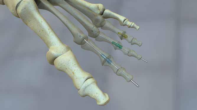
7 Step 6 Figure 5 Based on implant selection, choose the appropriate cannulated drill bit. Color-coded drill bits that correspond with the implant are provided in the system. The 2.2 mm implants correspond with the 1.7 mm diameter yellow drill bit, the 2.4 mm implants correspond with the 2.0 mm diameter green drill bit Figure 5, the 2.7 mm implants correspond with the 2.3 mm diameter magenta drill bit and the 2.9 mm implants correspond with the 2.5 mm diameter blue drill bit. Drill over the guide wire until the boss of the bit abuts the cut surface of the proximal phalanx. Figure 6 CAUTION: If the pilot hole is not drilled to the indicated depth, fully implanting the proximal, barbed portion of the implant may be difficult or not possible. Tip: If the bone is very dense and the cannulated drill is unable to drill to the appropriate depth, utilize the solid drill bits instead (the guide wire will need to be removed). Figure 6 Step 7 If the proximal phalanx is composed of moderate or dense bone and pinning to the MPJ is desired, the drilled pilot hole may require a lead-in. Select the appropriate reamer and attach it to the handle. Place the reamer over the wire and rotate until the boss of the reamer abuts the cut surface of the proximal phalanx. Figure 7 CAUTION: If guide wire fixation is not desired or the bone quality is poor, no reaming is advised. Figure 7 IFS Middle Phalanx Preparation Step 8 Remove the guide wire from the proximal phalanx and insert the trocar tip of the guide wire into the middle phalanx along its central axis. Verify the correct position of the guide wire with dorsal-plantar and medial-lateral fluoroscopy views. After the position has been verified, continue to drive the guide wire distally through both the middle and distal phalanges until it exits the toe. Continue to drive the guide wire distally (by engaging the wire driver s collet on the distal end of the guide wire and pulling) until the laser etched line on the conical tipped end of the wire just contacts the cut surface of the middle phalanx. Figure 8 Figure 8 Chapter 2 Surgical Technique 7


8 Figure 9 Step 9 A countersink is provided to ensure the implant drive feature can be buried below the cut surface of the middle phalanx. Insert the countersink into the handle provided. Figure 9 Place the countersink over the exposed wire and rotate several times so that the countersink shoulder bottoms out on the cut surface of the middle phalanx. Figure 10 Device Implantation and Toe Fixation Figure 10 Step 10 Select the implant that is preloaded onto the driver socket and attach the socket to the handle. Place the implant/handle assembly over the guide wire. Figure 11 Drive the threaded portion of the implant into the middle phalanx by screwing it in place. Continue to drive the threaded portion until the rim of the driver socket is completely within the pocket created by the countersink in the middle phalanx. Remove and dispose of the driver socket from the implant leaving the barbed portion of the implant exposed. Figure 12 Figure 11 CAUTION: Do not insert the implant over the wire unless it is retracted to the laser line because the implant will not be able to be inserted over the wire to the appropriate level and therefore unable to fully engage the middle phalanx. Note: If the guide wire was not advanced to the laser etched line in order to preserve the DIP joint, remove the guide wire prior to driving the implant into the middle phalanx. Figure 12 Step 11 Position the implant in axial alignment with the proximal phalanx drill hole. FIGURE 13 Insert the barbed portion of the implant into the pre-drilled hole in the proximal phalanx. Apply axial force (firmly compress the joint) until appropriate apposition is achieved between the middle and proximal phalanges. Figure 14 Confirm with fluoroscopy in multiple views. Any overhanging bone at the fusion site should be excised. CAUTION: Be aware that the sharp guide wire tip is exposed when implanting. Figure 13 Figure 14 8 Chapter 2 Surgical Technique


9 Tip: The impactor may be used to aid in fully seating the implant in the proximal phalanx. To use the impactor, assemble the impactor into the handle and place it over the wire and onto the distal phalanx. Tap the end of the handle until the middle and proximal phalanx meet. IFS-060 Step 12 Drive the conical tip of the guide wire proximally through the implant and back into the metatarsal to stabilize the MTP joint if desired. Figure 15 This will cause the barbed portion of the implant to splay and increase purchase in the proximal phalanx. Figure 16 Based on the surgeon s discretion, the guide wire fixation of the toe to the metatarsal can be left in place for the initial recovery period to allow the soft tissues to heal and prevent MTP joint subluxation. Optimal fixation strength is obtained by leaving the wire in the implant. Figure 15 Figure 16 CAUTION: If the guide wire does not pass through the implant following application of moderate force, turn off the wire driver. Use fluoroscopy to investigate any implant size or trajectory issues. If a guide wire does not pass through the implant following 2 3 brief attempts, the guide wire should be removed and the implant should be used without it, or a smaller diameter guide wire from the set may be inserted. CAUTION: The 0.8 mm guide wire should not be used to pin across the MPJ. Step 13 Verify the correction and the implant position in multiple views using fluoroscopy. Closure and Post-Operative Care Step 14 Close the surgical site according to surgical preference. If the guide wire is temporarily left in place, trim with wire cutters, and cover exposed end with a Jurgan ball. Post-operative care regimen should be assigned according to surgeon preference. NOTE: Surgeon discretion should be used when considering the appropriate guide wire diameter and duration of temporary fixation provided by the guide wire as wire fracture and pin tract infections are possible. Chapter 2 Surgical Technique 9


10 CANNULINK WITH EXT Step 1-2: See previous technique Step 3 The EXT implants are used in conjunction with the CANNULINK Standard implants that dock within the base of the EXT implant. The EXT implants are named and color coded according to the size of the CANNULINK Neutral implant they are compatible with. Primary Surgery: For use during a primary surgery the implants can be selected by evaluating the EXT implant over a guide wire under fluoroscopy. The profile of the EXT implant should fit within the outer boundary of the cortical shell of the proximal phalanx. Figure 17 Revision Surgery: For the revision of a previously implanted CANNULINK Neutral implant, select the correspondingly named EXT implant. CANNULINK Implant Part Number IFS N IFS N IFS N EXT Implant Part Number IFS N-15S IFS N-18S IFS N-15S IFS N-18S IFS N-16S IFS N-19S Wire Size 1.1 mm 1.4 mm 1.6 mm Note: Use only the guide wires supplied with the system. Proximal Phalanx Preparation Step 4 Figure 18 Base on the implant selected; insert the trocar tip of the corresponding guide wire (the side without the laser etched band) into the proximal phalanx along its central axis. Figure 18 Verify the correct position of the guide with dorsal-plantar and medial-lateral fluoroscopy views. The face planer can be used to correct the cut face of the proximal surface if it is not aligned to the trajectory of the wire. With the face planer loaded into the handle, rotate it back and forth over the guide wire until the bone surface is adequately prepped. Any residual bone on the margins of the phalanx can be removed with a rongeur. CAUTION: Correct trajectory is critical as incorrect placement of the wire may cause difficulty implanting the device or misalignment of the joint. Face Planer IFS-070-P CAUTION: When using the Face Planer, take care not to resect too much bone, especially on the middle phalanx. 10 Chapter 2 Surgical Technique


11 Step 5 Color-coded drill bits that correspond with each EXT implant are provided in the EXT caddy. The 2.4 mm implants correspond with the 3.3 mm diameter green drill bit, Figure 19 the 2.7 mm implants correspond with the 3.6 mm diameter magenta drill bit and the 2.9 mm implants correspond with the 3.8 mm diameter blue drill bit. Drill over the guide wire until the boss of the bit hits the cut surface of the proximal phalanx. Figure 20 Figure 19 Note: The smaller tip diameter of the EXT implant is self-drilling and self-tapping, therefore, it does not require predrilling the entire length of the EXT implant. CAUTION: If the pilot hole is not drilled to the indicated depth, fully implanting the base portion of the EXT implant may be difficult or not possible TIP: If the bone is very dense and the cannulated drill is unable to drill to the appropriate depth, utilize the solid drill bits (the guide wire will need to be removed). Figure 20 EXT Implantation Step 6 Insert the EXT implant into the proximal phalanx using the corresponding color-coded driver. Figure 21 Thread the EXT implant into the proximal phalanx until the hexagonal shoulder hits the resected face. Note: The hexagonal shoulder of the EXT implant must be left proud out of the proximal phalanx, but will reside within the countersink created in the middle phalanx. Figure 21 CAUTION: Driving the EXT implant too far into the proximal phalanx will prevent engagement of the CANNULINK Neutral implant. Middle Phalanx Preparation Step 7 Figure 22 Remove the guide wire from the proximal phalanx and insert the trocar tip of the guide wire into the middle phalanx along its central axis. Verify the correct position of the guide wire with dorsal-plantar and medial-lateral fluoroscopy views. After the position has been verified, continue to drive the guide wire distally through both the middle and distal phalanges until it exits the toe. Continue to drive the guide wire distally (by engaging the wire driver s collet on the distal end of the guide wire and pulling) until the laser etched line on the conical tipped end of the wire just contacts the cut surface of the middle phalanx. Figure 22 CAUTION: If excessive guide wire length is exposed from the middle phalanx, the implant will not be able to be inserted over the wire to the appropriate level and therefore unable to fully engage the middle phalanx. Tip: If guide wire fixation is not desired, do not disrupt the DIP joint or pass the wire distally out the toe. Chapter 2 Surgical Technique 11


12 Step 8 A countersink is provided to ensure the implant drive feature can be buried below the cut surface of the middle phalanx. Figure 23 Insert the countersink into the handle provided. Place the countersink over the exposed wire and rotate several times so that the countersink shoulder bottoms out on the cut surface of the middle phalanx. Figure 24 Figure 23 Figure 24 Device Implantation and Toe Fixation Step 9 Select the CANNULINK Standard implant that is preloaded onto the driver socket and attach the socket to the handle. Place the implant/handle assembly over the guide wire. Figure 25 Drive the threaded portion of the implant into the middle phalanx by screwing it in place. Continue to drive the threaded portion until the rim of the driver socket is completely within the pocket created by the countersink in the middle phalanx. Remove and dispose of the driver socket from the implant leaving the barbed portion of the implant exposed. Figure 26 Figure 25 CAUTION: Do not insert the implant over the wire unless it is retracted to the laser line because the implant will not be able to be inserted over the wire to the appropriate level and therefore unable to fully engage the middle phalanx. Note: If the guide wire was not advanced to the laser etched line in order to preserve the DIP joint, remove the guide wire prior to driving the implant into the middle phalanx. Figure Chapter 2 Surgical Technique
13 Step 10 Position the CANNULINK Standard implant in axial alignment with the EXT implant. Insert the barbed portion of the Standard implant into the EXT implant. Apply axial force (firmly compress the joint) until the implants dock with each other. Ensure apposition is achieved between the middle and proximal phalanges. Confirm with fluoroscopy in multiple views. Any overhanging bone at the fusion site should be excised. Tip: The impactor may be used to aid in fully seating the implant in the proximal phalanx. To use the impactor, assemble the impactor into the handle and place it over the wire and onto the distal phalanx. Tap the end of the handle until the middle and proximal phalanx meet. Note: The hex of the CANNULINK Standard implant must fully engage inside of the EXT for the construct to properly assemble. If engagement cannot be achieved with axial force, use the EXT driver to unthread (counter-clockwise rotation) the EXT implant by a half rotation. If the implant components still do not engage, use the hex driver for the Standard implant to unthread (counter-clockwise rotation) the Standard implant from the middle phalanx by a quarter rotation. Step 11 If desired, drive the conical tip of the guide wire proximally through the implant assembly and back into the metatarsal to stabilize the MTP joint. Based on the surgeon s discretion, the guide wire fixation of the toe to the metatarsal can be left in place for the initial recovery period to allow the soft tissues to heal and prevent MTP joint subluxation. Step 12 Verify the implant position in multiple views using fluoroscopy. Closure and Post-Operative Care Step 13 Close the surgical site according to surgical preference. If the guide wire is temporarily left in place, trim with wire cutters, and cover exposed end with a Jurgan ball. Post-operative care regimen should be assigned according to surgeon preference. NOTE: Surgeon discretion should be used when considering the appropriate guide wire diameter and duration of temporary fixation provided by the guide wire as wire fracture and pin tract infections are possible. Chapter 2 Surgical Technique 13


14 10 Figure 27 ANGLED CANNULINK TECHNIQUE Joint Preparation Step 1 Create an incision over the dorsal aspect of the PIP joint. Perform a transverse capsulotomy with release of the collateral ligaments off the head of the proximal phalanx. The joint dissection access should provide complete visualization of the articular surfaces of the middle and proximal phalanges. Figure 27 Step 2 Resect the distal head of the proximal phalanx just posterior to the head of the phalange. To utilize the angled implants, cut the proximal phalanx at a 10 degree angle in the plantar direction. Slight resection is also required of the subchondral bone on the proximal aspect of the middle phalanx. Figure 28 Figure 28 Figure 29 Tip: Place the middle and proximal phalanx as desired for fusion to verify the bones mate as desired. Figure 29 Implant Sizing Step 3 Determining the appropriate size implant is a critical step to the procedure. After the necessary resection has been accomplished, the appropriate implant size can be chosen. There are implant trial sizers in the set, one for each implant size. Select the neutral side of the sizer and hold it on the dorsal and lateral aspects of the bone and take fluoroscopic images in both dorsal-plantar and medial-lateral views. Figure 30 It is imperative that the entire profile of the trial sizer fit within the medullary canal of the phalange (it must not overlap the cortical shell). CAUTION: Do not insert the trial sizer into the bone. Lay the sizer over top of the bone for proper sizing. Figure 30 CAUTION: Correct implant sizing is critical. Implants that are oversized for a given anatomy can prevent the implant from being completely inserted into the proximal phalanx which may lead to the inability to fully reduce the joint. Fluoroscopic Images 14 Chapter 2 Surgical Technique


15 12 mm CannuLink Angled Implants 13 mm 14 mm Implant Selection Step 4 Select the implant size (determined from Step 3) and corresponding guide wire. Implant Part Number Implant Size Wire Size IFS A ø2.2mm 0.8mm IFS A ø2.4mm 1.1mm IFS A ø2.9mm 1.6mm ø2.2 mm ø2.4 mm ø2.9 mm Note: Use only the guide wires supplied with the system. Proximal Phalanx Preparation Step 5 Based on the size selected, insert the trocar tip of the corresponding guide wire into the proximal phalanx along its central axis. Verify the correct position of the guide wire with dorsal-plantar and medial-lateral fluoroscopy views. After the wire location has been verified, continue to advance the wire until it reaches the desired depth. Figure 31 Figure 31 Figure 32 CAUTION: Correct trajectory is critical, as incorrect placement of the wire may cause difficulty implanting the device or misalignment of the joint. Note: It is not recommended to utilize temporary guide wire fixation across the MPJ in conjunction with Angled CANNULINK Implants. Guide wires should only be utilized for proper intramedullary placement. Step 6 Based on implant selection, choose the appropriate cannulated drill bit. Color-coded drill bits that correspond with the implant are provided in the system. The 2.2 mm implants correspond with the 1.7mm diameter yellow drill bit, the 2.4mm implants correspond with the 2.0mm diameter green drill bit Figure 32 and the 2.9mm implants correspond with the 2.5mm diameter blue drill bit. Drill over the guide wire until the boss of the bit abuts the cut surface of the proximal phalanx. Figure 33 CAUTION: If the pilot hole is not drilled to the indicated depth, fully implanting the proximal, barbed portion of the implant may be difficult or not possible. Tip: If the bone is very dense and the cannulated drill is unable to drill to the appropriate depth, utilize the solid drill bits instead (the guide wire will need to be removed). Figure 33 Chapter 2 Surgical Technique 15


16 Middle Phalanx Preparation Step 7 Remove the guide wire from the proximal phalanx and insert the trocar tip of the guide wire into the middle phalanx along its central axis. Verify the correct position of the guide wire with dorsal-plantar and medial-lateral fluoroscopy views. Figure 34 After the position has been verified, continue to drive the guide wire distally through both the middle and distal phalanges until it exits the toe. Continue to drive the guide wire distally (by engaging the wire driver s collet on the distal end of the guide wire and pulling) until the laser etched line on the conical tipped end of the wire just contacts the cut surface of the middle phalanx. Figure 35 CAUTION: If excessive guide wire length is exposed from the middle phalanx, the implant will not be able to be inserted over the wire to the appropriate level and therefore unable to fully engage the middle phalanx. Tip: If preserving the DIP joint is desired, do not pass the wire distally out the toe. The wire will need to be removed after the countersinking for the drive feature. Figure 34 Figure 35 Step 8 A countersink is provided to ensure the implant drive feature can be buried below the cut surface of the middle phalanx. Insert the countersink into the handle provided. Figure 36 Place the countersink over the exposed wire and rotate several times so that the countersink shoulder bottoms out on the cut surface of the middle phalanx. Figure 37 Figure 36 Figure Chapter 2 Surgical Technique


17 Figure 38 Step 9 Select the implant that is preloaded onto the driver socket and attach the socket to the handle. Figure 38 Place the implant/handle assembly over the guide wire. Drive the threaded portion of the implant into the middle phalanx by screwing it in place. Continue to drive the threaded portion until the rim of the driver socket is completely within the pocket that was created by the countersink in the middle phalanx. The angled implant is orientation dependent. When the flat of the driver is pointed dorsally, the implant is angled plantar. Drive the screw portion of the implant until the words THIS SIDE UP are in line with the dorsal aspect of the middle phalanx. Figure 39 Remove and dispose the driver socket from the implant leaving the barbed portion of the implant exposed. Figure 40 Dorsal View Figure 39 Figure 40 Figure 41 CAUTION: Do not insert the implant over the wire unless it is retracted to the laser line because the implant will not be able to be inserted over the wire to the appropriate level and therefore unable to fully engage the middle phalanx. If the guide wire was not advanced to the laser etched line in order to preserve the DIP joint, remove the guide wire prior to driving the implant into the middle phalanx. Tip: If the surgeon removes the driver socket from the implant prior to achieving the correct, final orientation of the implant, the surgeon must reload the implant on the driver to spin the implant to the desired location. In order to do so, the angled barbed portion of the implant must point away from the flat surface of the driver with the text THIS SIDE UP. When the correct orientation is achieved, axial pressure will allow the implant drive mechanism to engage in the driver and the implant is reloaded. Step 10 Position the implant in axial alignment with the proximal phalanx drill hole. Insert the barbed portion of the implant into the pre-drilled hole in the proximal phalanx. Apply axial force (firmly compress the joint) until appropriate apposition is achieved between the middle and proximal phalanges. Figure 41 Confirm with fluoroscopy in multiple views. Any overhanging bone at the fusion site should be excised. Tip: The impactor may be used to aid in fully seating the implant in the proximal phalanx. To use the impactor, assemble the impactor into the handle and place it over the wire and onto the distal phalanx. Tap the end of the handle until the middle and proximal phalanx meet. Step 11 Verify the correction and the implant position in multiple views using fluoroscopy. Closure and Post-Operative Care Step 12 Remove the wire and close the surgical site according to surgical preference. Postoperative care regimen should be assigned according to surgeon preference. Chapter 2 Surgical Technique 17
18 Implants and Instruments APPENDIX STANDARD IMPLANTS Description Part # 2.2mm Implant & Driver Assembly 2.4mm Implant & Driver Assembly 2.7mm Implant & Driver Assembly 2.9mm Implant & Driver Assembly IFS IFS N IFS N IFS N OPTIONAL IMPLANTS Description Part # 2.4mm Max Implant & Driver Assembly 2.9mm Max Implant & Driver Assembly 2.2mm Angled Implant & Driver Assembly 2.4mm Angled Implant & Driver Assembly 2.9mm Angled Implant & Driver Assembly IFS IFS IFS A IFS A IFS A EXT IMPLANTS Description Part # 2.4mm 15mm EXT Implant IFS N-15S 2.4 mm 18mm EXT Implant IFS N-18S 2.7 mm 15mm EXT Implant IFS N-15S 2.7mm 18 mm EXT Implant IFS N-18S 2.9mm 16mm EXT Implant IFS N-16S 2.9mm 19mm EXT Implant IFS N-19S 18 CANNULINK Intraossous Fixation System
19
20 1023 Cherry Road Memphis, TN Nesbitt Avenue South Bloomington, MN and denote Trademarks and Registered Trademarks of Wright Medical Group N.V., or its affiliates Wright Medical Group N.V. or its affiliates. All Rights Reserved. IFS REV B ECN Apr-2016
Contents. Chapter 1 4 Chapter Chapter Chapter Chapter 5 15
 Contents Chapter 1 4 Chapter 2 5 5 Chapter 3 6 6 7 Chapter 4 8 8 8 8 9 10 10 11 12 13 14 14 Chapter 5 15 Introduction Intended Use Indications Device Description Implant Options and Sizing Instrumentation
DuaFit. Proximal Interphal angeal Impl ant
 DuaFit Proximal Interphal angeal Impl ant DUAFIT - TABLE OF CONTENTS PRODUCT DESCRIPTION 3 INDICATIONS 6 SURGICAL TECHNIQUE #1 7 Without guide wire (DuaFit 0 10 17 ) SURGICAL TECHNIQUE #2 14 With guide
CSS. Cannulated Screw System SURGICAL TECHNIQUE
 CSS Cannulated Screw System SURGICAL TECHNIQUE Contents Chapter 1 4 Product Information 4 Device Description Chapter 2 5 Intended Use 5 Indications 5 Contraindications Chapter 3 6 Surgical Technique Appendix
HammerFUZE HAMMERTOE COMPRESSION SYSTEM SURGICAL TECHNIQUE
 HammerFUZE HAMMERTOE COMPRESSION SYSTEM SURGICAL TECHNIQUE HammerFUZE HAMMERTOE COMPRESSION SYSTEM SURGICAL TECHNIQUE Design Rationale The HammerFUZE Hammertoe Compression System was designed to simplify
Correction System. Surgical Technique
 Nextra Hammertoe Correction System Surgical Technique Maximized Bone Purchase* Stable and Secure Phalanx Optimized Screw Design Adjustable Bone-to-Bone Apposition Progressive Ratchet Tightening Mechanism
Correction System. Surgical Technique
 Nextra Hammertoe Correction System Surgical Technique Maximized Bone Purchase* Stable and Secure Phalanx Optimized Screw Design Adjustable Bone-to-Bone Apposition Progressive Ratchet Tightening Mechanism
PHALINX. Hammertoe Fixation SURGICAL TECHNIQUE
 PHALINX Hammertoe Fixation SURGICAL TECHNIQUE Contents Chapter 1 4 Product Information 4 Device Description Chapter 2 5 Intended Use 5 Indications 5 Contraindications Chapter 3 6 Surgical Technique 6
TORNIER BIO-RSA. Bony Increased Offset - Reversed Shoulder Arthroplasty SURGICAL TECHNIQUE
 TORNIER BIO-RSA Bony Increased Offset - Reversed Shoulder Arthroplasty SURGICAL TECHNIQUE 2 Table of Contents: Concept...4 Bony Increased Offset Reversed Shoulder Arthroplasty (BIO-RSA ) Concept...4 Surgical
Conventus CAGE PH Surgical Techniques
 Conventus CAGE PH Surgical Techniques Conventus Orthopaedics The Conventus CAGE PH (PH Cage) is a permanent implant comprised of an expandable scaffold, made from nitinol and titanium, which is deployed
SURGICAL TECHNIQUE GUIDE
 DANGER indicates an imminently hazardous situation which, if not avoided, will result in death or serious injury. WARNING indicates a potentially hazardous situation which, if not avoided, could result
Surgical Technique. Customer Service:
 Patent and Patent Pending CAUTION: Federal Law (USA) restricts this device to sale by or on the order of a physician. INDICATIONS FOR USE The Axis Charcot Fixation System in diameters of 5.5, 6.5 and 7.5mm
Surgical Technique 4.5/8.5MM BEAMING SYSTEM. Customer Service:
 Patent and Patent Pending CAUTION: Federal Law (USA) restricts this device to sale by or on the order of a physician. INDICATIONS FOR USE The 4.5/8.5 screw system is intended for fixation arthrodesis of
CHARLOTTE. 7.0 Multi-Use Compression Screw System SURGICAL TECHNIQUE
 CHARLOTTE 7.0 Multi-Use Compression Screw System SURGICAL TECHNIQUE Contents Chapter 1 1 Chapter 2 2 2 3 4 Appendix A 5 6 Appendix B 7 8 Preoperative Planning Surgical Technique Subtalar Arthrodesis Guide
Integra. DigiFuse Cannulated Intramedullary Fusion System SURGICAL TECHNIQUE
 Integra DigiFuse Cannulated Intramedullary Fusion System SURGICAL TECHNIQUE Table of Contents Design Rationale... 2 System Features... 2 Indications... 2 Contraindications... 2 Surgical Technique...3 Step
ORTHOLOC 3Di. Foot Reconstruction System SURGIC AL TECHNIQUE
 ORTHOLOC 3Di Foot Reconstruction System S C R E W TA R G E T I N G G U I D E SURGIC AL TECHNIQUE SURGEON DESIGN TEAM The ORTHOLOC 3Di Foot Reconstruction System was developed in conjuction with: ORTHOLOC
SURGICAL TECHNIQUE GUIDE: JONES FRACTURE USING THE PRECISION JONES FRACTURE SCREW SYSTEM
 PRODUCT DESCRIPTION The PRECISION Jones Fracture Screw System offers extensive options of Type II Anodized Titanium screws. System-specific instrumentation is designed to address procedural challenges
Technique Guide Hammertoe Correction System
 Technique Guide Hammertoe Correction System TM The ToeMATE Hammertoe Correction System is an easy to implant bone screw system intended for the correction of hammertoe deformity. It is provided in a complete
3. PATIENT POSITIONING & FRACTURE REDUCTION 3 8. DISTAL GUIDED LOCKING FOR PROXIMAL NAIL PROXIMAL LOCKING FOR LONG NAIL 13
 Contents IMPLANT FEATURES 2 1. INDICATIONS 3 2. PRE-OPERATIVE PLANNING 3 3. PATIENT POSITIONING & FRACTURE REDUCTION 3 4. INCISION 4 5. ENTRY POINT 4-6 6. PROXIMAL NAIL INSERTION 6-7 7. PROXIMAL LOCKING
Lesser MPJ Hemi Implant
 Lesser MPJ Hemi Implant Surgical Technique Contents Product The BioPro Lesser MPJ Hemi Implant is a simple, durable, metallic hemiarthroplasty resurfacing prosthesis for the treatment of arthritis, Freiberg
Foot & Ankle. Smart Toe II. Intramedullary Implant. Operative Technique. Foot & Ankle
 Foot & Ankle Smart Toe II Intramedullary Implant Operative Technique Foot & Ankle Smart Toe This publication sets forth detailed recommended procedures for using Stryker Osteosynthesis devices and instruments.
COMPARING KIRSCHNER WIRE FIXATION TO A NEW DEVICE USED FOR PROXIMAL INTERPHALANGEAL FUSION
 C H A P T E R 3 0 COMPARING KIRSCHNER WIRE FIXATION TO A NEW DEVICE USED FOR PROXIMAL INTERPHALANGEAL FUSION Scott R. Roman, DPM INTRODUCTION The most common fixation for proximal interphalangeal fusion
MICRONAIL. Intramedullary Distal Radius System SURGICAL TECHNIQUE
 MICRONAIL II Intramedullary Distal Radius System SURGICAL TECHNIQUE Contents Introduction 3 4 Chapter 1 5 Chapter 2 6 Appendix A 18 Appendix B 19 Surgeon Design Team Introduction Product Information Surgical
MICA. Minimally Invasive Foot Surgery CHEVRON OSTEOTOMY SURGIC AL TECHNIQUE
 MICA Minimally Invasive Foot Surgery CHEVRON OSTEOTOMY SURGIC AL TECHNIQUE Contents Chapter 1 4 Introduction Chapter 2 5 Indications and Warnings Chapter 3 6 Patient Positioning and Set Up Chapter 4 7
System. Humeral Nail. Surgical Technique
 System Humeral Nail Surgical Technique Contents IMPLANT FEATURES 2 1. INDICATIONS 3 2. PRE-OPERATIVE PLANNING 3 3. PATIENT POSITIONING & FRACTURE REDUCTION 3 4. INCISION 4 5. ENTRY POINT 4-6 6. PROXIMAL
CHARLOTTE. 3.0 and 4.3 Multi-Use Compression Screws SURGIC A L T ECHNIQUE
 CHARLOTTE 3.0 and 4.3 Multi-Use Compression Screws SURGIC A L T ECHNIQUE CHARLOTTE 3.0 and 4.3 Multi-Use Compression Screws SURGICAL TECHNIQUE Surgical Technique as described by: Robert Anderson, MD Bruce
DARCO. Bow 2 Plate SURGIC AL TECHNIQUE
 DARCO Bow 2 Plate SURGIC AL TECHNIQUE Contents 2 Preface 3 Chapter 1 4 Chapter 2 5 6 7 8 9 Appendix 10 10 11 Intended Use Indications/Contraindications Design Rationale Preoperative Planning Surgical Technique
Surgical Technique Carpal Fusion
 Carpal Fusion Patent and Patent Pending CAUTION: Federal Law (USA) restricts this device to sale by or on the order of a physician. INDICATIONS FOR USE The Extremity Medical Lag Screw and X-Post System
Foot and Ankle Technique Guide Proximal Inter-Phalangeal (PIP) Fusion
 Fusion") Surgical Technique Foot and Ankle Technique Guide Proximal Inter-Phalangeal (PIP) Fusion Prepared in consultation with: Phinit Phisitkul, MD Department of Orthopedics and Rehabilitation University of Iowa
Surgical Technique Foot and Ankle Technique Guide Proximal Inter-Phalangeal (PIP) Fusion Prepared in consultation with: Phinit Phisitkul, MD Department of Orthopedics and Rehabilitation University of Iowa
LMH. Minimal Bone Resection. Lesser Metatarsal Head Implant. Thin, low-profile design for minimal bone resection
 Minimal Bone Resection LMH Lesser Metatarsal Head Implant Thin, low-profile design for minimal bone resection Stem offset dorsally for anatomically correct alignment in medullary canal Rectangular shape
Surgical Technique. CONQUEST FN Femoral Neck Fracture System
 Surgical Technique CONQUEST FN Femoral Neck Fracture System Table of Contents Introduction... 3 Indications... 3 Product Overview... 4 Surgical Technique... 5 Patient Positioning... 5 Reduce the Fracture...
CHARLOTTE Lisfranc. Recontruction System SURGICAL TECHNIQUE
 CHARLOTTE Lisfranc Recontruction System SURGICAL TECHNIQUE Contents Preface 3 Chapter 1 4 Chapter 2 4 4 4 4 4 Chapter 3 5 5 5 6 6 6 7 7 8 Chapter 4 8 8 9 10 Appendix 10 Introduction Indications and Contraindications
Implantable K-wire SURGIC A L T ECHNIQUE
 Implantable K-wire SURGIC A L T ECHNIQUE Contents Chapter 1 4 Product Information 4 Device Description 4 Indications 4 Contraindications Chapter 2 5 Surgical Technique 5 Hammertoe Correction 6 MTP Joint
Zimmer NexGen MIS Tibial Component. Cemented Surgical Technique IMAGE TO COME
 Zimmer NexGen MIS Tibial Component Cemented Surgical Technique IMAGE TO COME Zimmer NexGen MIS Tibial Component Cemented Surgical Technique 1 Zimmer NexGen MIS Tibial Component Cemented Surgical Technique
CHARLOTTE. 7.0 Multi-Use Compression Screw System SURGICAL TECHNIQUE
 CHARLOTTE 7.0 Multi-Use Compression Screw System SURGICAL TECHNIQUE Contents Chapter 1 1 Chapter 2 2 Chapter 3 3-9 Chapter 4 10-12 Appendix A 13-14 Design Rationale Screw Behavior Surgical Technique Procedure
DYNAMIC, TRANSVERSE COMPRESSION. Low Profile, Anatomic Design, Type II Anodized. Mechanical Compression Designed to Stimulate the Fusion Process
 CoLink_XP_ST_080218.pdf 1 8/2/18 8:36 AM SURGICAL TECHNIQUE CoLink XP Plates DYNAMIC, TRANSVERSE COMPRESSION C M Y CM MY CY CMY K MTP Std. Plate MTP Revision Plate Lapidus Standard +1mm and +2mm Y Plate
Surgical Technique Guide
 Surgical Technique Guide Minimally Invasive, Intramedullary Device For Distal Radius Fragility Fractures The Sonoma WRx Wrist Fracture Repair Device is flexible, inserting easily through a small incision
SURGICAL TECHNIQUE CHI. Cannulated Hemi Implants 1 ST MPJ ARTHROPLASTY
 CHI Cannulated Hemi Implants 1 ST MPJ ARTHROPLASTY SURGICAL TECHNIQUE CHI Cannulated Hemi Implants Design Rationale Pain of the great toe joint often leads to altered lifestyles. The goal of MPJ implant
Lateral TTC Plate SURGICAL TECHNIQUE
 MAXLOCK EXTREME Lateral TTC Plate SURGICAL TECHNIQUE Contents Overview 2 Exposure 3 Surgical Technique 4 Implants and Instruments 10 11 Proper surgical procedures and techniques are the responsibility
AcUMEDr. Olecranon Threaded Compression Rod
 AcUMEDr Olecranon Threaded Compression Rod Olecranon Threaded Compression Rod Since 1988, Acumed has been designing solutions to the demanding situations facing orthopaedic surgeons, hospitals and their
AEQUALIS PERFORM + REVERSED
 TO R N I E R AEQUALIS PERFORM + REVERSED Glenoid WEDGED AUGMENT SURGIC AL TECHNIQUE Table of Contents: AEQUALIS PERFORM + REVERSED Glenoid...3 Overview...3 Indications/Contraindications...4 Pre-Operative
Zimmer Small Fragment Universal Locking System. Surgical Technique
 Zimmer Small Fragment Universal Locking System Surgical Technique Zimmer Small Fragment Universal Locking System 1 Zimmer Small Fragment Universal Locking System Surgical Technique Table of Contents Introduction
RFS. Resorbable Fixation System SURGICAL TECHNIQUE
 RFS Resorbable Fixation System SURGICAL TECHNIQUE Product Information RFS Resorbable Material - PLGA - What is it? The RFS Pins and Solid/Cannulated Screws are made of PLGA, a bioabsorbable poly lactic/glycolic
ORTHOLOC 3Di. Foot Reconstruction System Midfoot Fusion Plate SURGICAL TECHNIQUE
 ORTHOLOC 3Di Foot Reconstruction System Midfoot Fusion Plate SURGICAL TECHNIQUE ORTHOLOC Foot Reconstruction System Midfoot Fusion Plate SURGICAL TECHNIQUE Surgeon Design Team The ORTHOLOC 3Di Foot Reconstruction
Technique Guide. LCP Proximal Femoral Hook Plate 4.5/5.0. Part of the LCP Periarticular Plating System.
 Technique Guide LCP Proximal Femoral Hook Plate 4.5/5.0. Part of the LCP Periarticular Plating System. Table of Contents Introduction Features and Benefits 2 AO ASIF Principles 4 Indications 5 Surgical
wave Calcaneal Fracture Plate
 wave Calcaneal Fracture Plate s u r g i c a l t e c h n i q u e Tornier WAVE Calcaneal fracture plate system surgical procedure Indications for Use: The Tornier Calcaneal Fracture Plate System is indicated
SALVATION 3Di. Plating System SURGICAL TECHNIQUE
 SALVATION 3Di Plating System SURGICAL TECHNIQUE Contents Chapter 1 4 Introduction Chapter 2 5 Intended use 5 Indications 5 Contraindications Chapter 3 6 Device Description Chapter 4 7 Preoperative Planning
Zimmer ITST Intertrochanteric/ Subtrochanteric Fixation System. Abbreviated Surgical Technique
 Zimmer ITST Intertrochanteric/ Subtrochanteric Fixation System Abbreviated Surgical Technique ITST System Abbreviated Surgical Technique Indications The ITST Intramedullary Nail is indicated for use in
Foot & Ankle. EasyClip. Osteosynthesis Compression Staples. Foot & Ankle
 Foot & Ankle EasyClip Osteosynthesis Compression Staples Foot & Ankle Operative Technique EasyClip Osteosynthesis Compression Staples 2 This publication sets forth detailed recommended procedures for using
Surgical Technique. Clavicle Locking Plate
 Surgical Technique Clavicle Locking Plate PERI-LOC Locked Plating System Clavicle Locking Plate Surgical Technique Table of Contents Introduction...2 Indications...3 Plate Features...3 Patient Positioning...4
InCoreTM Lapidus System
 InCoreTM Lapidus System Precision Guided Correction Surgical Technique InCore TM Lapidus System Precision Guided Correction Tri-Planar Correction Targeting Guide is intended to aid and stabilize angular/rotational
Cervical Solutions. Optio-C Anterior Cervical Plate. with Allograft/Autograft. Surgical Technique Guide
 Cervical Solutions Optio-C Anterior Cervical Plate with Allograft/Autograft Surgical Technique Guide 2 Optio-C Anterior Cervical Plate with Allograft/Autograft Surgical Technique Guide The Optio-C System
Surgical Technique. Forearm Fracture Solutions
 Surgical Technique Forearm Fracture Solutions Acumed is a global leader of innovative orthopaedic and medical solutions. We are dedicated to developing products, service methods, and approaches that improve
Zimmer NexGen Trabecular Metal Tibial Tray
 Zimmer NexGen Trabecular Metal Tibial Tray Surgical Technique Zimmer NexGen Trabecular Metal Tibial Tray Surgical Technique Give Bone A Solid Hold Zimmer NexGen Trabecular Metal Tibial Tray Surgical Technique
TORNIER SIMPLICITI. Shoulder System SURGICAL TECHNIQUE
 TORNIER SIMPLICITI Shoulder System SURGICAL TECHNIQUE Table of Contents: Indications & Contraindications... 4 System Compatibility & Pre-operative Planning... 4 Humeral Head Resection... 6 Freehand Resection
GRAVITY Plantar Plate Repair System SURGIC AL TECHNIQUE
 GRAVITY Plantar Plate Repair System SURGIC AL TECHNIQUE Contents PREFACE Preface 4 4 5 5 Chapter 1 6 6 7 8 9 11 12 13 13 Appendix 14 Introduction Positioning Indications Contraindications Surgical Technique
Surgical Technique. Distal Humerus Locking Plate
 Surgical Technique Distal Humerus Locking Plate PERI-LOC Locked Plating System Distal Humerus Locking Plate Surgical Technique Table of Contents Introduction...2 Indications...3 Plate Features...3 Patient
Surgical Technique. Olecranon Locking Plate
 Surgical Technique Olecranon Locking Plate PERI-LOC Locked Plating System Olecranon Locking Plate Surgical Techniquealog Infor Table of Contents Introduction...2 Indications...3 Plate Features...3 Patient
MIS Cemented Tibial Component
 MIS Cemented Tibial Component NexGen Complete Knee Solution Surgical Technique Table of Contents Surgical Exposure... 2 Finish the Tibia... 2 Position Based on Anatomic Landmarks... 3 Lateral Posterior
LOWER EXTREMITIES SINGLE-USE INSTRUMENTATION SURGICAL IMPLANTATION TECHNIQUE. First Metatarsal Phalangeal Joint FOOT THE DIFFERENCE IS MOVING.
 LOWER EXTREMITIES SINGLE-USE INSTRUMENTATION SURGICAL IMPLANTATION TECHNIQUE First Metatarsal Phalangeal Joint FOOT THE DIFFERENCE IS MOVING. CARTIVA SYNTHETIC CARTILAGE IMPLANT SURGICAL IMPLANTATION TECHNIQUE
Distal Cut First Femoral Preparation
 Surgical Technique Distal Cut First Femoral Preparation Primary Total Knee Arthroplasty LEGION Total Knee System Femoral preparation Contents Introduction...3 DCF femoral highlights...4 Preoperative planning...6
SURGICAL TECHNIQUE GUIDE: LAPIDUS ARTHRODESIS USING THE PHANTOM INTRAMEDULLARY NAIL INTRAMEDULLARY NAIL
 LAPIDUS ARTHRODESIS USING THE PHANTOM INTRAMEDULLARY NAIL INTRAMEDULLARY NAIL LAPIDUS ARTHRODESIS USING THE PHANTOM INTRAMEDULLARY NAIL Acknowledgment: Paragon 28 would like to thank James T. Clancy, DPM
Technique Guide. 3.5 mm LCP Low Bend Medial Distal Tibia Plate Aiming Instruments. Part of the 3.5 mm LCP Percutaneous Instrument System.
 Technique Guide 3.5 mm LCP Low Bend Medial Distal Tibia Plate Aiming Instruments. Part of the 3.5 mm LCP Percutaneous Instrument System. Table of Contents Introduction 3.5 mm LCP Low Bend Medial Distal
SMV Scientific Bone Plate and Screw System Surgical Technique
 SMV Scientific Bone Plate and Screw System Surgical Technique Description: The SMV Scientific Bone Plate and Screw System consists of non-locking plates and bone screw fasteners in a variety of lengths,
AxSOS Locking Plate System
 AxSOS Locking Plate System Operative Technique Small Fragment Basic Fragment 1 2 Contents Page 1. Introduction 4 2. Features & Benefits 5 4 and 5mm Compression Plates 5 Reconstruction and 1/3 Tubular Locking
TABLE OF CONTENTS. 2 (8144 Rev 2)
") 1 (8144 Rev 2) TABLE OF CONTENTS Introduction Conventus CAGE TM - Proximal Humerus...3 Indications and Contraindications...4 Surgical Summary...5 Patient Positioning & Approach...6 Surgical Technique Plate
1 (8144 Rev 2) TABLE OF CONTENTS Introduction Conventus CAGE TM - Proximal Humerus...3 Indications and Contraindications...4 Surgical Summary...5 Patient Positioning & Approach...6 Surgical Technique Plate
Locking Radial Head Plates
 Locking Radial Head Plates Locking Radial Head Plates Since 1988, Acumed has been designing solutions to the demanding situations facing orthopaedic surgeons, hospitals and their patients. Our strategy
Flower Medium Headless & Cannulated Screws
 Flower Medium Headless & Cannulated Screws PROCEDURE GUIDE www.flowerortho.com The Flower Foot & Ankle Application NC FUSION PLATE 2-HOLE COMPRESSION PLATE TMT FUSION PLATE LAPIDUS FUSION PLATE COMPRESSION
Hemi Phalangeal Implant SURGICAL TECHNIQUE
 SURGICAL TECHNIQUE SIZING AND ORDERING HEAD WIDTH A HEAD HEIGHT B HPI-0001 1 16.9 12 HPI-0002 2 19.5 13.8 HPI-0003 3 22.4 15.9 PART NO. A B SIZE DIMENSIONS ARE IN MILLIMETERS. The HPI stemmed prosthesis,
Arcos Interlocking Distal Stem. Surgical Technique Addendum to the Arcos Modular Femoral Revision System
 Arcos Interlocking Distal Stem Surgical Technique Addendum to the Arcos Modular Femoral Revision System One Surgeon. One Patient. Over 1 million times per year, Biomet helps one surgeon provide personalized
Surgical Technique. VISIONAIRE FastPak Instruments for the LEGION Total Knee System
 Surgical Technique VISIONAIRE FastPak Instruments for the LEGION Total Knee System VISIONAIRE FastPak for LEGION Instrument Technique* Nota Bene The technique description herein is made available to the
BLUEPRINT. 3D Planning + PSI SURGIC AL TECHNIQUE
 TO R N I E R BLUEPRINT 3D Planning + PSI SURGIC AL TECHNIQUE V 1. 5. 3 P O LYA M I D E Contents 4 5 6 7 9 Patient Specific Instrumentation Overview 3D Planning PSI Guide Creation and Order Use of PSI
Headless Compession Screw 2.5 / 3.0
 SURGICAL TECHNIQUE Headless Compession Screw 2.5 / 3.0 Titanium or Stainless Steel Cannulated Headless Design Multiple Thread Options Torx Driver Sterile and Non-Sterile Options Simple Instrumentation
Anchorage. Foot & Ankle. Plating System. Operative Technique
 Foot & Ankle Anchorage Plating System Operative Technique Foot & Ankle Anchorage Plate System MTP Plates Lapidus Plates Lisfranc Plates Basal Osteotomy Plates Utility Plates Anchorage Cross Plate System
A locking plate system that expands a surgeon s options in trauma surgery. Zimmer NCB Plating System
 A locking plate system that expands a surgeon s options in trauma surgery Zimmer NCB Plating System The Power of Choice The power of having true intraoperative options is at your fingertips. Using standard
Acutrak 2 Headless Compression Screw System Micro, Mini, and Standard Screws. Supplemental Use Guide Four Corner Fusion
 Acutrak 2 Headless Compression Screw System Micro, Mini, and Standard Screws Supplemental Use Guide Four Corner Fusion Acumed is a global leader of innovative orthopaedic and medical solutions. We are
Correction System. Surgical Technique
 Re+Line Bunion Correction System Surgical Technique Bunion Correction System Easy insertion and medial placement accuracy using Landmark Guide technology 1 mm compression slot and fixed tines to encourage
NeoGen Tibia Nail System
 NeoGen Tibia Nail System LESS IS MORE TE-2070-03 Surgical Technique BLE OF CONTENT Preface Surgical Technique Appendix Products Information Patient Preparation Entry Portal Fracture Reduction Canal Preparation
Biotrak Resorbable Fixation System
 Surgical Technique Biotrak Resorbable Fixation System Acumed is a global leader of innovative orthopaedic and medical solutions. We are dedicated to developing products, service methods, and approaches
Surgical Technique. Targeter Systems Overview
 Surgical Technique Targeter Systems Overview PERI-LOC Locked Plating System Targeter Systems Overview Table of contents Product overview... 2 Introduction... 2 Indications... 2 Design features and benefits...
CrossTIE. PIP Arthrodesis Implant. surgical technique ordering information PEEK IMPLANTS PEEK IMPLANTS ALLOGRAFT IMPLANTS CROSSTIE INSERTER
 ordering information x x 0o 1443-3301 1444-3300 x x 10o 1443-3311 1444-3310 2.5mm x 2.5mm x 0o 1443-2501 1444-2500 2.5mm x 2.5mm x 10o 1443-2511 1444-2510 ALLOGRAFT IMPLANTS * Sterile Packaged in Saline,
Olecranon Osteotomy Nail. For simple fractures and osteotomies of the olecranon.
 Olecranon Osteotomy Nail. For simple fractures and osteotomies of the olecranon. Technique Guide Discontinued June 2016; AVAILABLE FOR IMPLANT REMOVAL PURPOSES ONLY DSEM/TRM/0517/0843 Table of Contents
Technique Guide. *smith&nephew N8TIVE ACL Anatomic ACL Reconstruction System
 Technique Guide *smith&nephew N8TIVE ACL Anatomic ACL Reconstruction System N8TIVE ACL System The N8TIVE ACL Anatomic Reconstruction System provides a novel and simple approach to ACL repair. The N8TIVE
Surgical Technique. Calcaneal Locking Plate
 Surgical Technique Calcaneal Locking Plate PERI-LOC Locked Plating System Calcaneal Locking Plate Surgical TechniqueCatalog Infor Table of Contents Introduction...2 Indications...3 Plate Features...3 Patient
Technique Guide. 3.5 mm LCP Olecranon Plates. Part of the Synthes locking compression plate (LCP) system.
 system.") Technique Guide 3.5 mm LCP Olecranon Plates. Part of the Synthes locking compression plate (LCP) system. Table of Contents Introduction 3.5 mm LCP Olecranon Plates 2 AO Principles 3 Indications 3 Clinical
Technique Guide 3.5 mm LCP Olecranon Plates. Part of the Synthes locking compression plate (LCP) system. Table of Contents Introduction 3.5 mm LCP Olecranon Plates 2 AO Principles 3 Indications 3 Clinical
CHARLOTTE. Compression Staple
 CHARLOTTE Compression Staple CHARLOTTE compression staple surgical technique SURGICAL ADVISORS ROBERT ANDERSON, MD BRUCE COHEN, MD W. HODGES DAVIS, MD Proper surgical procedures and techniques are the
humerus InSafeLOCK Nail
 humerus InSafeLOCK Nail Introduction Content Humerus InSafeLOCK Nail is an innovative intramedullary nailing system, developed for humerus problems. Humerus fractures have 5-6 % incidence of all bone fractures.
The AperFix II System
 The AperFix II System A Complete Anatomic Solution Transtibial Surgical Technique 2 AperFix II System Transtibial Surgical Technique Figure 1 A Complete Anatomic Solution The Cayenne Medical AperFix and
LCP Medial Distal Tibia Plate, without Tab. The Low Profile Anatomic Fixation System with Angular Stability and Optimal Screw Orientation.
 LCP Medial Distal Tibia Plate, without Tab. The Low Profile Anatomic Fixation System with Angular Stability and Optimal Screw Orientation. Technique Guide LCP Small Fragment System Table of Contents Introduction
AcUMEDr. FoREARM ROD SYSTEM
 AcUMEDr FoREARM ROD SYSTEM FoREARM ROD SYSTEM Since 1988 Acumed has been designing solutions to the demanding situations facing orthopedic surgeons, hospitals and their patients. Our strategy has been
Surgical Technique. Proximal Humerus Locking Plate
 Surgical Technique Proximal Humerus Locking Plate PERI-LOC Upper Extremity Locked Plating System 3.5mm & 4.5mm Proximal Humerus Locking PlatesCatalog Infor Table of Contents Introduction.........................................................2
Technique Guide. 6.5 mm Midfoot Fusion Bolt. For intramedullary fixation of the medial column of the foot.
 Technique Guide 6.5 mm Midfoot Fusion Bolt. For intramedullary fixation of the medial column of the foot. Table of Contents Introduction 6.5 mm Midfoot Fusion Bolt 2 AO Principles 4 Indications 5 Surgical
Zimmer MIS Periarticular 3.5mm Proximal Tibial Locking Plate
 Zimmer MIS Periarticular 3.5mm Proximal Tibial Locking Plate Surgical Technique The Science of the Landscape Zimmer MIS Periarticular 3.5mm Proximal Tibial Locking Plate Surgical Technique 1 Zimmer MIS
The Flower Medial Column Fusion Plate
 The Flower Medial Column Fusion Plate PROCEDURE GUIDE www.flowerortho.com The Flower Foot & Ankle Application NC FUSION PLATE 2-HOLE COMPRESSION PLATE TMT FUSION PLATE LAPIDUS FUSION PLATE COMPRESSION
The Vilex FUZETM. Dual Thread Screw & Intramedullary Nail in One Implant. The Ultimate TTC Arthrodesis Internal Fixator
 The Vilex FUZETM Dual Thread Screw & Intramedullary Nail in One Implant The Ultimate TTC Arthrodesis Internal Fixator Introduction The Vilex FUZE TM TTC Arthrodesis Compression Nail combines the attributes
CARTIVA. Synthetic Cartilage Implant SURGICAL IMPLANTATION TECHNIQUE. First Metatarsal Phalangeal Joint THE DIFFERENCE IS MOVING.
 CARTIVA Synthetic Cartilage Implant SURGICAL IMPLANTATION TECHNIQUE First Metatarsal Phalangeal Joint THE DIFFERENCE IS MOVING. CARTIVA SYNTHETIC CARTILAGE IMPLANT TABLE OF CONTENTS Introduction... 3 Cartiva
Hip Resurfacing System
 Hip Resurfacing System The Arthrosurface HemiCAP Hip Hemiarthroplasty System restores the articular surface geometry of the femoral head and preserves functional structures using an innovative 3 dimensional
DARCO. LPS Plate SURGICAL TECHNIQUE
 DARCO LPS Plate SURGICAL TECHNIQUE Contents Preface 3 Chapter 1 4 Chapter 2 5 5 6 7 9 Appendix 10 10 11 Design Rationale Preoperative Planning Surgical Technique Surgical Approach Joint Preparation Surgical
CHARLOTTE. Snap-Off Screws SURGICAL TECHNIQUE
 CHARLOTTE Snap-Off Screws SURGICAL TECHNIQUE CHARLOTTE snap-off screws surgical technique SURGICAL ADVISORS ROBERT ANDERSON, MD BRUCE COHEN, MD W. HODGES DAVIS, MD Proper surgical procedures and techniques
AxSOS. Locking Plate System. Operative Technique. Small Fragment Basic Fragment
 AxSOS Locking Plate System Operative Technique Small Fragment Basic Fragment Stryker Plating Contents Page 1. Introduction 4 2. Features & Benefits 5 4 and 5 Compression Plates 5 Reconstruction and 1/3
STRENGTH FROM WITHIN. Surgical Technique for Representatives
 STRENGTH FROM WITHIN Surgical Technique for Representatives Table of Contents PREOPERATIVE TEMPLATING... p.3 OUTRIGGER DRILL GUIDE OVERVIEW... p.4 PATIENT POSITIONING...p.5 STEP 1: REDUCE THE FRACTURE...p.5-6