RFS. Resorbable Fixation System SURGICAL TECHNIQUE
|
|
|
- Harvey Marsh
- 6 years ago
- Views:
Transcription


1 RFS Resorbable Fixation System SURGICAL TECHNIQUE

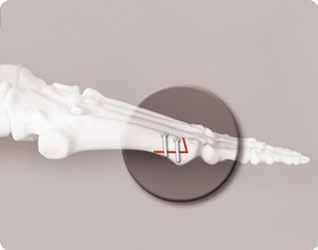
2 Product Information RFS Resorbable Material - PLGA - What is it? The RFS Pins and Solid/Cannulated Screws are made of PLGA, a bioabsorbable poly lactic/glycolic acid copolymer (PLGA). These polymers have a long history of safe medical use and they degrade in vivo by hydrolysis into alpha-hydroxy acids that are metabolized by the body. The manufacturing process generates the high initial mechanical strength and stiffness of the screws. A special characteristic of the RFS screw is auto-compression. It is a lengthwise contraction of the screw by 1-2% (Figure 1), and related expansion in the diameter of the screw once the screw is implanted and hydrolysis begins. This memory effect, based on mechanical activity, both creates compression on the fracture line and prevents the screw from loosening as metal screws commonly do. The fixation achieved with the RFS Screw improves by itself over the first postoperative weeks. Wright s RFS Screw is the only bioabsorbable screw offering controlled longterm compression on the healing fracture. The RFS Pin s functionality begins during surgery with instant locking due to the grooved surface design (Figure 2), and they actively contribute to improving fixation after implantation due to a self-locking property based on a hydrolytical shape memory. The product s properties create optimal conditions for bone repair, leading to better ossification. Using the RFS Pin allows surgeons to attend to more patients, as the removal procedure is no longer needed. Figure 1: Auto Compression Figure 2: RFS Grooved Surface Design Tornier RFS Screw Arthrex TRIM-IT Screw * ConMed/Linvatec SmartScrew II ** BioMet/Arthrotek Reunite Screw *** Inion Optima Screw (Inion OTPS Screw) **** CHARACTERISTICS Time to Strength Loss (<80%) 8-16 weeks >24 weeks weeks 8-12 weeks weeks Resorption Time approx. 2 years N/A 2-4 years 9-15 months 2-4 years References: * ** *** ****


3 Industry standard screw thread with detachable adaptor The RFS Cannulated Screws are constructed of oriented bioresorbable L-lactic/co-glycolic acid copolymer (PLGA 85L/15G) and feature a small, low-profile resorbable screw head, industry standard compatible screw thread design and a detachable industry standard compatible head adaptor offering ease of insertion and greater confidence. The cannulated screw and associated instruments provide for precise placement and procedural simplicity. The RFS Advantage Feature 85/15 PLGA Maintains Strength Through the Healing Process Fully Cannulated System Bioabsorbability Auto Compression Multiple Applications Accepts Additional Strength Fully Threaded and Lag Options Advantage The copolymer degrades in vivo by hydrolysis into alpha hydroxy acids that are metabolized by the body. The RFS Cannulated Screw is designed to maintain its functional structure for at least 8 weeks and to completely resorb within approximately 2 years. Allows the screw to be precisely placed for maximum purchase. No retained hardware = no hardware prominence or hardware removal. The implant is designed to change its dimensional characteristics in hydrolytic conditions. Diameter increases and length decreases 1% - 2% compared to initial dimensions. This innovative feature provides sustained compression during bone healing and reduces the risk of unstable fixation. Indicated for fixation of bone fractures, osteotomies, arthrodeses, bone grafts and osteochondral fractures of upper extremity, ankle and foot in the presence of appropriate immobilization. 4.0 mm and 4.5 mm RFS Cannulated Screw can be used, applying a combination technique with a 1.5 mm RFS by inserting the pin inside an RFS Cannulated Screw. Allows for multiple techniques.
.")

 using an appropriate cannulated drill bit.")
4 Surgical Technique 1 2 Insert guide wire through the drill sleeve to appropriate depth under image intensification. Optional Technique: Insert additional guide wire for extra stabilization and guidance. Countersink (optional). In areas where soft tissue coverage is minimal, and when the head of the fully threaded screw is needed as additional support, the appropriate countersink can be used in order to make space for the screw head and to avoid soft tissue irritation by the protruding screw head. Use appropriate cannulated countersink without drill sleeve. 4 5 Select the appropriate RFS Cannulated Screw for the indication. Drill the screw hole through the drill sleeve to a sufficient depth under image intensification (not including the last 5 mm of the guide wire) using an appropriate cannulated drill bit. Use irrigation. 7 Tap the screw hole manually through the drill sleeve to a sufficient depth using an appropriate cannulated bone tap. 8 Fully insert the screw along the guide wire into the drill hole. NOTE: When the reduction is good and drilling and tapping are done properly, the insertion should be easy with the two finger technique. In case the friction increases too much during insertion, the screw must be removed and the hole must be rinsed and/or retapped. Remove and discard the guide wire. After the screw is fully inserted, the Insertion Adapter must be detached from the screw (e.g. with screwdriver or with pliers). Once detached, dispose the Insertion Adapter. After insertion in cases where the screw head is not needed (e.g. in the case of the syndesmosis screw), the screw is cut along the bone or plate surface after insertion to avoid soft tissue irritation by the protruding screw head. Scissors, reciprocating saw or a hot wire can be used to cut the RFS Cannulated Screw. DO NOT cut the head of a LAG-screw.


5 3 Measure the screw length by sliding the tapered end of the cannulated depth gauge along the guide wire to the bone surface. If countersink has been used, the measuring device must be placed at the bottom of the countersink. Read the scale at the end of the guide wire to determine appropriate screw length. This reading will place the screw 5 mm short of the guide wire tip to maintain the stabilization effect of the guide wire throughout the procedure. Optional Technique to Increase Strength In cases where more shear strength of the implant is needed, it is possible to increase strength of the 4.0 mm and 4.5 mm RFS Cannulated Screws by inserting the 1.5 mm RFS Pin implant inside the cannulated screw (e.g. with the RFS Pin Applicator). This technique also allows the RFS Pin to fill the distal end of the guide wire hole to increase the overall strength of the screw. The 3.5 mm RFS Cannulated Screw can NOT be used with the RFS Pin. 6 A B The prepared hole should be irrigated prior to screw insertion to flush out bone debris. Open the RFS Cannulated Screw Holder cap. Pick the screw out of the RFS Cannulated Screw Holder by the appropriate cannulated screwdriver. Select appropriate length of the 1.5 mm RFS Pin implant and insert pin inside the RFS Cannulated Screw with customized RFS instrumentation according to the normal insertion technique of the RFS Pin. Insert RFS Pin fully into the hole to reach the distal end of the guide wire hole with the grooved pin. Detach the Instrument from the pin. After insertion, in cases where the pin is too long, the proximal portion of the pin may be cut flush to the surface of the screw head (with a hot wire) to avoid soft tissue irritation by the protruding pin. Optional Technique for Steps 1-8 In areas where soft tissue coverage is more than 20 mm, protection sleeve can be inserted through a small incision and all the steps can be done through the sleeve to prevent soft tissue damage. In step 6, the surgeon must remove the insertion adapter from screw before insertion and insert the screw with the customized direct driver through the protection sleeve. Remove the guide wire after insertion. Additional Information On the basis of the surgeon s decision, radiographs are taken before wound closure. After fixation, the wound is closed in layers applying standard principles of orthopaedics and traumatology. Meticulous hemostasis and complete primary skin closure over the implant are essential.


6 Product Information Universal screw head adaptor RFS Solid Screw The RFS Screws are constructed of oriented bioresorbable L-lactic/co-glycolic acid copolymer (PLGA 85L/15G) and feature a small, low-profile resorbable screw head, industry standard compatible screw thread design and a detachable industry standard compatible head adaptor offering ease of insertion and greater confidence. The RFS Advantage Feature Advantage 85/15 PLGA The copolymer degrades in vivo by hydrolysis into alpha hydroxy acids that are metabolized by the body. Maintains Strength Through the Healing Process The RFS Pin is designed to maintain its functional structure for at least 8 weeks and to completely resorb within approximately 2 years. Bioabsorbability No retained hardware = no hardware prominence or hardware removal. Auto Compression The implant is designed to change its dimensional characteristics in hydrolytic conditions. Diameter increases and length decreases 1% - 2% compared to initial dimensions. This innovative feature provides sustained compression during bone healing and reduces the risk of unstable fixation. AO Compatibility Industry standard compatible design with detachable screw head. RFS Solid Screw Competitive Product Multiple Applications Indicated for fixation of bone fractures, osteotomies, arthrodeses, bone grafts and osteochondral fractures of upper extremity, ankle and foot in the presence of appropriate immobilization. Fully Threaded and Lag Options Allows for multiple techniques. Small, low profile screw head
 before screw insertion.")
7 Surgical Technique 1 2 Select the appropriate RFS Solid Screw for the indication. Drill a screw channel through the fracture plane using appropriate drill bit. Use irrigation. Tap the screw hole manually to a sufficient depth using the appropriate AO-compatible bone tap (corresponding to the screw diameter) before screw insertion. Make sure to tap the drill canal all the way in. 3 4 When the head of the fully threaded screw is needed as additional support, appropriate countersink can be used in order to make space for the screw head and to avoid soft tissue irritation by the protruding screw head. 5 Hold the screwdriver and the screw parallel to the long axis of the drill hole and insert the screw fully into the drill hole. NOTE: When the reduction is good and drilling and tapping are done properly, the insertion should be easy with the two finger technique. In case the friction increases too much during insertion, the screw must be removed and the hole must be rinsed and/or retapped. The prepared hole should be irrigated prior to screw insertion to flush out bone debris. Open the RFS Solid Screw Holder cap. Pick the screw out of the RFS Screw Holder by the appropriate AO-compatible screwdriver. 6 After the screw is fully inserted, the Insertion Adapter must be detached from the screw by pulling and slightly bending the adapter with the screwdriver. Do NOT try to twist the adapter loose. Once detached, dispose the Insertion Adapter. Additional Information After insertion in cases where the screw head is not needed (e.g. in the case of the syndesmosis screw), the screw is cut along the bone or plate surface after insertion to avoid soft tissue irritation by the protruding screw head. Scissors, reciprocating saw or a hot wire can be used to cut the RFS Solid Screw. DO NOT cut the head of a LAG-screw. On the basis of the surgeon s decision, radiographs are taken before wound closure. After fixation, the wound is closed in layers applying standard principles of orthopaedics and traumatology. Meticulous hemostasis and complete primary skin closure over the implant are essential.

8 Product Information RFS Pin Cross-section The RFS Pins are constructed of bioabsorbable lactic/glycolic acid copolymer (85/15 PLGA). These polymers have a long history of safe medical use and they degrade in vivo by hydrolysis into alpha hydroxy acids that are metabolized by the body. The implants functionality begins during surgery with instant locking due to the grooved surface design, and they actively contribute to improving fixation after implantation due to a self-locking property based on a hydrolytical shape memory. The RFS Advantage Feature 85/15 PLGA Maintains Strength Through the Healing Process Advantage The copolymer degrades in vivo by hydrolysis into alpha hydroxy acids that are metabolized by the body. The RFS Pin is designed to maintain its functional structure for at least 8 weeks and to completely resorb within approximately 2 years. Multiple Applications Indicated for bone fractures, osteotomies, arthrodeses and osteochondral fractures in the presence of appropriate immobilization. Auto Compression Allows for the RFS Pin to expand 1-2% in hydrolytic conditions. Grooved Design Ridges on the outer surface of the pin resist rotation. Applicator Piston Plastic Sleeve Scored Guide Wire Note: The Guide Wire for the 2.0 mm Pin has a stepped shaft to accommodate standard pin drivers. RFS Pins are 50 mm long and are available in 1.5 mm, 2.0 mm and 2.7 mm diameters individually packaged in a Pin Holder.


9 Surgical Technique 1 2 Select the appropriate RFS Pin for the indication. Drill a hole which corresponds to the pin diameter through the fracture/osteotomy plane. To prevent overdrilling, multiple reaming with the drill bit should be avoided. Open the RFS Pin Holder cap. Pick the pin by pushing the RFS Pin Applicator Piston/ Arthroscopic Piston distal head into the RFS Pin Holder until it is attached to the pin. 3 4 Slide attached pin and piston inside to the RFS Pin Applicator Sleeve through the twist lock by twisting the Piston clockwise. 5 During insertion of the pin, hold the applicator and the pin parallel to the long axis of the drill hole so that it slides easily to the drill hole. Insert the pin by lightly tapping the Piston with a mallet. Introduce the pin into the hole by sliding the Piston. 6 Tap the Piston until entire pin is forced fully into the drill hole. The RFS Pin Applicator is designed so that it sinks the pin 1-2 mm when the Piston is tapped to the end of the sleeve. This prevents the head of the pin from protruding which could cause soft tissue irritation. Additional Information After insertion, if the pin is too long, scissors, reciprocating saw, or a hot wire can be used to cut the RFS Pin. In such a case, the proximal end of the pin must be pushed 1-2 mm below the cortical surface or smoothened at least to the cortical level, to avoid soft tissue irritation. Two or more pin fixations can be applied if necessary (depending on the nature and size of the fracture). In such a case, it is recommended that pins be inserted at divergent angles to one another, rather than parallel, for best results. On the basis of the surgeon s decision, radiographs are taken before wound closure. After fixation, the wound is closed in layers applying standard principles of orthopaedics and traumatology. Meticulous hemostasis and complete primary skin closure over the implant are essential.


10 Indication and Procedure Matrix Scarf Osteotomy Phalangeal Fusion Closing Wedge Closing Wedge Osteotomy Maleolar


11 Chevron/Austin Bunionectomy Calcaneal Slide Osteotomy Syndesmotic Reverdin Green
12 Ordering Information RFS Cannulated Screw Product Information The RFS Cannulated Screw system includes a procedurespecific instrument set and screws in the following sizes: RFS Solid Screw Product Information The RFS Solid Screw system includes a procedure-specific instrument set and screws in the following sizes: Diameter Length Diameter Length 3.5 mm Cannulated 24 mm - 40 mm 3.5 mm Cannulated LAG 24 mm - 45 mm 4.0 mm Cannulated 35 mm - 90 mm 4.0 mm Cannulated LAG 35 mm - 90 mm 4.5 mm Cannulated 40 mm - 90 mm 4.5 mm Cannulated LAG 40 mm - 90 mm RFS Cannulated Screw Indications: The RFS Cannulated Screw is indicated for fixation of bone fractures, osteotomies, arthrodeses, bone grafts and osteochondral fractures of the upper extremity, ankle and foot in the presence of appropriate immobilization. RFS Cannulated Screw Contraindications: Fractures and osteotomies of diaphyseal bone (except in the hand and foot) Situations where internal fixation is otherwise contraindicated, e.g., active or potential infection and where patient s cooperation cannot be guaranteed 2.7 mm Fully Threaded 14 mm - 24 mm 3.5 mm Fully Threaded 14 mm - 40 mm 3.5 mm LAG 20 mm - 45 mm 4.5 mm Fully Threaded 35 mm - 90 mm 4.5 mm LAG 30 mm - 50 mm RFS Solid Screw Indications: The RFS Screw is indicated for fixation of bone fractures, osteotomies, arthrodeses, bone grafts and osteochondral fractures of the upper extremity, ankle and foot in the presence of appropriate immobilization. RFS Solid Screw Contraindications: Fractures and osteotomies of diaphyseal bone (except in the hand & foot) Situations where internal fixation is otherwise contraindicated, e.g., active or potential infection and where patient s cooperation cannot be guaranteed RFS Pin Information Each RFS DPA contains a scored Guide Wire for pre-drilling and measurement, an Applicator Piston for aseptic Pin access, and an Applicator Sleeve to facilitate accurate insertion. Pin Size Pin CAT# DPA CAT# 1.5 mm RFS -P015 RFS -PA mm RFS -P020 RFS -PA mm RFS -P027 RFS -PA27 RFS Pin Surgical Indications: Fixation of bone fractures, osteotomies, arthrodeses and osteochondral fractures in the presence of appropriate immobilization. Prior to using any Wright device, please review the instructions for use and surgical technique for a complete listing of indications, contraindications, warnings, precautions, potential adverse events, and directions for use. RFS Pin Contraindications: Fractures and osteotomies of diaphyseal bone (except in the hand & foot) Fractures and osteotomies in weight bearing cancellous bone Situations where internal fixation is otherwise contraindicated, e.g., active or potential infection and where patient s cooperation cannot be guaranteed 1023 Cherry Road Memphis, TN Nesbitt Avenue South Bloomington, MN RFS is a trademark or registered trademark of Tornier in the U. S. and other countries. Trademarks and Registered marks of Wright Medical Technology, Inc Wright Medical Technology, Inc. All Rights Reserved. CAW-4708 rev C ECN Jan-2016
Inion FreedomScrew Syndesmosis Repair. Biodegradable Fixation System
 Inion FreedomScrew Syndesmosis Repair Biodegradable Fixation System Inion FreedomScrew for Syndesmosis Repair Inion FreedomScrew is a strong and versatile resorbable screw for orthopaedic fixations. Because
LCP Medial Distal Tibia Plate, without Tab. The Low Profile Anatomic Fixation System with Angular Stability and Optimal Screw Orientation.
 LCP Medial Distal Tibia Plate, without Tab. The Low Profile Anatomic Fixation System with Angular Stability and Optimal Screw Orientation. Technique Guide LCP Small Fragment System Table of Contents Introduction
Biotrak Resorbable Fixation System
 Surgical Technique Biotrak Resorbable Fixation System Acumed is a global leader of innovative orthopaedic and medical solutions. We are dedicated to developing products, service methods, and approaches
Surgical Technique. CONQUEST FN Femoral Neck Fracture System
 Surgical Technique CONQUEST FN Femoral Neck Fracture System Table of Contents Introduction... 3 Indications... 3 Product Overview... 4 Surgical Technique... 5 Patient Positioning... 5 Reduce the Fracture...
Biomet Large Cannulated Screw System
 Biomet Large Cannulated Screw System s u r g i c a l t e c h n i q u e A Complete System for Simplified Fracture Fixation 6.5mm & 7.3mm The Titanium, Self-drilling, Self-tapping Large Cannulated Screw
Technique Guide. 3.5 mm LCP Low Bend Medial Distal Tibia Plates. Part of the Synthes locking compression plate (LCP) system.
 system.") Technique Guide 3.5 mm LCP Low Bend Medial Distal Tibia Plates. Part of the Synthes locking compression plate (LCP) system. Table of Contents Introduction 3.5 mm LCP Low Bend Medial Distal Tibia Plates
Technique Guide 3.5 mm LCP Low Bend Medial Distal Tibia Plates. Part of the Synthes locking compression plate (LCP) system. Table of Contents Introduction 3.5 mm LCP Low Bend Medial Distal Tibia Plates
DARCO. Bow 2 Plate SURGIC AL TECHNIQUE
 DARCO Bow 2 Plate SURGIC AL TECHNIQUE Contents 2 Preface 3 Chapter 1 4 Chapter 2 5 6 7 8 9 Appendix 10 10 11 Intended Use Indications/Contraindications Design Rationale Preoperative Planning Surgical Technique
A locking plate system that expands a surgeon s options in trauma surgery. Zimmer NCB Plating System
 A locking plate system that expands a surgeon s options in trauma surgery Zimmer NCB Plating System The Power of Choice The power of having true intraoperative options is at your fingertips. Using standard
Surgical Technique. Calcaneal Locking Plate
 Surgical Technique Calcaneal Locking Plate PERI-LOC Locked Plating System Calcaneal Locking Plate Surgical TechniqueCatalog Infor Table of Contents Introduction...2 Indications...3 Plate Features...3 Patient
CANNULINK. Intraossous Fixation System SURGICAL TECHNIQUE
 CANNULINK Intraossous Fixation System SURGICAL TECHNIQUE Contents Chapter 1 4 Introduction The CANNULINK Advantage Indications for Use Preoperative Planning Chapter 2 5 Surgical Technique CANNULINK Standard
Surgical Technique. Clavicle Locking Plate
 Surgical Technique Clavicle Locking Plate PERI-LOC Locked Plating System Clavicle Locking Plate Surgical Technique Table of Contents Introduction...2 Indications...3 Plate Features...3 Patient Positioning...4
CHARLOTTE Lisfranc. Recontruction System SURGICAL TECHNIQUE
 CHARLOTTE Lisfranc Recontruction System SURGICAL TECHNIQUE Contents Preface 3 Chapter 1 4 Chapter 2 4 4 4 4 4 Chapter 3 5 5 5 6 6 6 7 7 8 Chapter 4 8 8 9 10 Appendix 10 Introduction Indications and Contraindications
MetaFix Ludloff Plate
 Merete MetaFix Ludloff Plate Low Profile Locking Bone Plate System Surgical Technique and Ordering Information - Content - Content 1. Description.................................................. 3 2.
3. Insert Tocar Sleeves Insert the NCB tissue protection sleeve assembly 1.6 to 10mm through a skin incision (Fig. 38).
.") NCB Proximal Humerus Plating System Surgical Technique 19 2. Temporary Plate Fixation The plate can be temporary fixed to the bone with 1.6mm K-wire through the proximal cannulated fixation screw of the
NCB Proximal Humerus Plating System Surgical Technique 19 2. Temporary Plate Fixation The plate can be temporary fixed to the bone with 1.6mm K-wire through the proximal cannulated fixation screw of the
LCP Distal Tibia Plate
 Surgical Technique LCP Locking Compression Plate Original Instruments and Implants of the Association for the Study of Internal Fixation AO/ASIF Table of contents Indications 3 Implants/Instruments 5 Surgical
Low Bend Distal Tibia Plates
 Part of the DePuy Synthes Locking Compression Plate (LCP ) System 3.5 mm LCP Low Bend Medial Distal Tibia Plates Surgical Technique Table of Contents Introduction 3.5 mm LCP Low Bend Medial Distal Tibia
Surgical Technique. Distal Humerus Locking Plate
 Surgical Technique Distal Humerus Locking Plate PERI-LOC Locked Plating System Distal Humerus Locking Plate Surgical Technique Table of Contents Introduction...2 Indications...3 Plate Features...3 Patient
Surgical Technique. Olecranon Locking Plate
 Surgical Technique Olecranon Locking Plate PERI-LOC Locked Plating System Olecranon Locking Plate Surgical Techniquealog Infor Table of Contents Introduction...2 Indications...3 Plate Features...3 Patient
A locking plate system that expands a surgeon s options in trauma surgery. Zimmer NCB Plating System
 A locking plate system that expands a surgeon s options in trauma surgery Zimmer NCB Plating System The Power of Choice The power of having true intraoperative options is at your fingertips. Using standard
Surgical Technique. Proximal Humerus Locking Plate
 Surgical Technique Proximal Humerus Locking Plate PERI-LOC Upper Extremity Locked Plating System 3.5mm & 4.5mm Proximal Humerus Locking PlatesCatalog Infor Table of Contents Introduction.........................................................2
Zimmer Small Fragment Universal Locking System. Surgical Technique
 Zimmer Small Fragment Universal Locking System Surgical Technique Zimmer Small Fragment Universal Locking System 1 Zimmer Small Fragment Universal Locking System Surgical Technique Table of Contents Introduction
PHALINX. Hammertoe Fixation SURGICAL TECHNIQUE
 PHALINX Hammertoe Fixation SURGICAL TECHNIQUE Contents Chapter 1 4 Product Information 4 Device Description Chapter 2 5 Intended Use 5 Indications 5 Contraindications Chapter 3 6 Surgical Technique 6
Zimmer ITST Intertrochanteric/ Subtrochanteric Fixation System. Abbreviated Surgical Technique
 Zimmer ITST Intertrochanteric/ Subtrochanteric Fixation System Abbreviated Surgical Technique ITST System Abbreviated Surgical Technique Indications The ITST Intramedullary Nail is indicated for use in
wave Calcaneal Fracture Plate
 wave Calcaneal Fracture Plate s u r g i c a l t e c h n i q u e Tornier WAVE Calcaneal fracture plate system surgical procedure Indications for Use: The Tornier Calcaneal Fracture Plate System is indicated
A sequenced approach to flush graft placement. GLENOID BONE LOSS SYSTEM Procedural Solution
 A sequenced approach to flush graft placement GLENOID BONE LOSS SYSTEM Procedural Solution One comprehensive system, two ways of treating glenoid bone loss The GLENOID BONE LOSS SYSTEM provides you with
Surgical Technique. Anterolateral and Medial Distal Tibia Locking Plates
 Surgical Technique Anterolateral and Medial Distal Tibia Locking Plates PERI-LOC Periarticular Locked Plating System Anterolateral and Medial Distal Tibia Locking Plates Surgical Technique Contents Product
AcUMEDr. BIoTRAKt Resorbable Pin
 AcUMEDr BIoTRAKt Resorbable Pin Biotrak Pin Since 1988, Acumed has been designing solutions to the demanding situations facing orthopaedic surgeons, hospitals and their patients. Our strategy has been
ARTHROTUNNELER TUNNELPRO SYSTEM
 TORNIER ARTHROTUNNELER TUNNELPRO SYSTEM Transosseous Rotator Cuff Repair SURGICAL TECHNIQUE ARTHROTUNNELER TUNNELPRO SYSTEM ARTHROTUNNELER Surgical Technique Step 1. Drill medial tunnel(s) to a positive
Surgical Technique. Fibula Rod System
 Surgical Technique Fibula Rod System Acumed is a global leader of innovative orthopaedic and medical solutions. We are dedicated to developing products, service methods, and approaches that improve patient
3. PATIENT POSITIONING & FRACTURE REDUCTION 3 8. DISTAL GUIDED LOCKING FOR PROXIMAL NAIL PROXIMAL LOCKING FOR LONG NAIL 13
 Contents IMPLANT FEATURES 2 1. INDICATIONS 3 2. PRE-OPERATIVE PLANNING 3 3. PATIENT POSITIONING & FRACTURE REDUCTION 3 4. INCISION 4 5. ENTRY POINT 4-6 6. PROXIMAL NAIL INSERTION 6-7 7. PROXIMAL LOCKING
Technique Guide. 3.5 mm LCP Low Bend Medial Distal Tibia Plate Aiming Instruments. Part of the 3.5 mm LCP Percutaneous Instrument System.
 Technique Guide 3.5 mm LCP Low Bend Medial Distal Tibia Plate Aiming Instruments. Part of the 3.5 mm LCP Percutaneous Instrument System. Table of Contents Introduction 3.5 mm LCP Low Bend Medial Distal
Merete BLP. Surgical Technique. - Bunion Locking Plate - Low Profile Locking Bone Plate System
 Merete BLP - Bunion Locking Plate - Low Profile Locking Bone Plate System Surgical Technique Merete Medical, Inc. 49 Purchase Street Rye, N.Y. 10580 Phone: 914 967-1532 www.merete-medical.com - Surgical
Orthopedic Bone Nail System - Distal Femoral Nail Surgical Technique Manual
 Orthopedic Bone Nail System - Distal Femoral Nail Surgical Technique Manual Note: The surgical procedures should be performed under the guidance of qualified skilled orthopedic surgeons, and this surgical
Surgical Technique International Version. Clavicle Locking Plate
 Surgical Technique International Version Clavicle Locking Plate PERI-LOC Upper Extremity Locked Plating System Clavicle Surgical Techniquefor Table of Contents Introduction........................................................2
System. Humeral Nail. Surgical Technique
 System Humeral Nail Surgical Technique Contents IMPLANT FEATURES 2 1. INDICATIONS 3 2. PRE-OPERATIVE PLANNING 3 3. PATIENT POSITIONING & FRACTURE REDUCTION 3 4. INCISION 4 5. ENTRY POINT 4-6 6. PROXIMAL
Fibula Rod System. Lateral Malleolus Fracture Indications:
 Fibula Rod System Fibula Rod System Since 1988, Acumed has been designing solutions for the demanding situations facing orthopaedic surgeons, hospitals and their patients. Our strategy has been to know
Flexible Fragment Fixation. Surgical Technique
 Flexible Fragment Fixation Surgical Technique 2 F 3 Flexible Fragment Fixation The F 3 Fragment Plating System offers low profile, yet strong fixation in a locked plating construct that can be contoured
TORNIER BIO-RSA. Bony Increased Offset - Reversed Shoulder Arthroplasty SURGICAL TECHNIQUE
 TORNIER BIO-RSA Bony Increased Offset - Reversed Shoulder Arthroplasty SURGICAL TECHNIQUE 2 Table of Contents: Concept...4 Bony Increased Offset Reversed Shoulder Arthroplasty (BIO-RSA ) Concept...4 Surgical
OBSOLETED. LCP Medial Distal Tibia Plate, without Tab. The Low Profile Anatomic Fixation System with Angular Stability and Optimal Screw Orientation.
 LCP Medial Distal Tibia Plate, without Tab. The Low Profile Anatomic Fixation System with Angular Stability and Optimal Screw Orientation. Surgical Technique LCP Small Fragment System This publication
Correction System. Surgical Technique
 Nextra Hammertoe Correction System Surgical Technique Maximized Bone Purchase* Stable and Secure Phalanx Optimized Screw Design Adjustable Bone-to-Bone Apposition Progressive Ratchet Tightening Mechanism
Lateral TTC Plate SURGICAL TECHNIQUE
 MAXLOCK EXTREME Lateral TTC Plate SURGICAL TECHNIQUE Contents Overview 2 Exposure 3 Surgical Technique 4 Implants and Instruments 10 11 Proper surgical procedures and techniques are the responsibility
Technique Guide. 6.5 mm Midfoot Fusion Bolt. For intramedullary fixation of the medial column of the foot.
 Technique Guide 6.5 mm Midfoot Fusion Bolt. For intramedullary fixation of the medial column of the foot. Table of Contents Introduction 6.5 mm Midfoot Fusion Bolt 2 AO Principles 4 Indications 5 Surgical
Locking Ankle Plating System. Surgical Technique
 Locking Ankle Plating System Surgical Technique Acumed is a global leader of innovative orthopaedic and medical solutions. We are dedicated to developing products, service methods, and approaches that
Technique Guide. 3.5 mm LCP Olecranon Plates. Part of the Synthes locking compression plate (LCP) system.
 system.") Technique Guide 3.5 mm LCP Olecranon Plates. Part of the Synthes locking compression plate (LCP) system. Table of Contents Introduction 3.5 mm LCP Olecranon Plates 2 AO Principles 3 Indications 3 Clinical
Technique Guide 3.5 mm LCP Olecranon Plates. Part of the Synthes locking compression plate (LCP) system. Table of Contents Introduction 3.5 mm LCP Olecranon Plates 2 AO Principles 3 Indications 3 Clinical
Zimmer Trabecular Metal Ankle Interpositional Spacer and Trabecular Metal Ankle Fusion Spacer
 Zimmer Trabecular Metal Ankle Interpositional Spacer and Trabecular Metal Ankle Fusion Spacer Surgical Technique 2 Zimmer Trabecular Metal Ankle Interpositional Spacer and Trabecular Metal Ankle Fusion
TABLE OF CONTENTS. 2 (8144 Rev 2)
") 1 (8144 Rev 2) TABLE OF CONTENTS Introduction Conventus CAGE TM - Proximal Humerus...3 Indications and Contraindications...4 Surgical Summary...5 Patient Positioning & Approach...6 Surgical Technique Plate
1 (8144 Rev 2) TABLE OF CONTENTS Introduction Conventus CAGE TM - Proximal Humerus...3 Indications and Contraindications...4 Surgical Summary...5 Patient Positioning & Approach...6 Surgical Technique Plate
Surgical Technique. Cannulated Angled Blade Plate 3.5 and 4.5, 90
 Surgical Technique Cannulated Angled Blade Plate 3.5 and 4.5, 90 Cannulated Angled Blade Plate 3.5 and 4.5, 90 Table of contents Indications/Contraindications 2 Implants 3 Surgical technique 5 Implant
Axi+LineTM Proximal Bunion CorrectionSystem. Surgical Technique
 Axi+LineTM Proximal Bunion CorrectionSystem Surgical Technique A i Line Proximal Bunion Correction System TM Desired angle correction is built into the plate, providing a self-reducing, 5-hole construct
PEDUS-L. Locking Plantar Lapidus Plate
 PEDUS-L Locking Plantar Lapidus Plate Page 1 PEDUS-L - Locking Plantar Lapidus Plate Table of Contents Implants 3 System 4 Operation manual 5 Approach 5 Identification of the TMT 1 joint with a cannula
Correction System. Surgical Technique
 Nextra Hammertoe Correction System Surgical Technique Maximized Bone Purchase* Stable and Secure Phalanx Optimized Screw Design Adjustable Bone-to-Bone Apposition Progressive Ratchet Tightening Mechanism
Surgical Technique Carpal Fusion
 Carpal Fusion Patent and Patent Pending CAUTION: Federal Law (USA) restricts this device to sale by or on the order of a physician. INDICATIONS FOR USE The Extremity Medical Lag Screw and X-Post System
Technique Guide. 2.7 mm/3.5 mm LCP Distal Fibula Plates. Part of the Synthes locking compression plate (LCP) system.
 system.") Technique Guide 2.7 mm/3.5 mm LCP Distal Fibula Plates. Part of the Synthes locking compression plate (LCP) system. Table of Contents Introduction 2.7 mm/3.5 mm LCP Distal Fibula Plates 2 AO Principles
Technique Guide 2.7 mm/3.5 mm LCP Distal Fibula Plates. Part of the Synthes locking compression plate (LCP) system. Table of Contents Introduction 2.7 mm/3.5 mm LCP Distal Fibula Plates 2 AO Principles
Surgical Technique. Targeter Systems Overview
 Surgical Technique Targeter Systems Overview PERI-LOC Locked Plating System Targeter Systems Overview Table of contents Product overview... 2 Introduction... 2 Indications... 2 Design features and benefits...
LCP Distal Humerus Plates
 The anatomic fixation system for the distal humerus with angular stability Surgical technique LCP Locking Compression Plate Contents Indications and contraindications 2 Implants 3 Instruments 5 Preparation
CHARLOTTE. Compression Staple
 CHARLOTTE Compression Staple CHARLOTTE compression staple surgical technique SURGICAL ADVISORS ROBERT ANDERSON, MD BRUCE COHEN, MD W. HODGES DAVIS, MD Proper surgical procedures and techniques are the
Resorbable Orthopedic Fixation System
 TM Resorbable Orthopedic Fixation System Made exclusively from Resorbable Copolymer The Resorbable Orthopedic Mesh Panel and Sheet System Resorbable fixation that s as easy as 1 LactoSorb Copolymer 82%
Technique Guide Hammertoe Correction System
 Technique Guide Hammertoe Correction System TM The ToeMATE Hammertoe Correction System is an easy to implant bone screw system intended for the correction of hammertoe deformity. It is provided in a complete
Double Engine Orthopedic Bone Nail System Universal Humeral Nail
 Double Engine Orthopedic Bone Nail System ----------- Universal Humeral Nail Surgical Technique Manual Note: The surgical procedures should be performed under the guidance of qualified skilled orthopedic
SURGICAL TECHNIQUE GUIDE
 DANGER indicates an imminently hazardous situation which, if not avoided, will result in death or serious injury. WARNING indicates a potentially hazardous situation which, if not avoided, could result
Small Fragment Plating System
 Small Fragment Plating System Securing optimal fixation through locked and compression plating technology SURGICAL TECHNIQUE RECOVERY FUNCTION SURVIVORSHIP DePuy believes in an approach to trauma surgery
Technique Guide. Locking Attachment Plate. For treatment of periprosthetic fractures.
 Technique Guide Locking Attachment Plate. For treatment of periprosthetic fractures. Table of Contents Introduction Locking Attachment Plate 2 Indications 4 Surgical Technique Patient Positioning 5 Preparation
LCP Low Bend Medial Distal Tibia Plates 3.5 mm. Anatomic plates with low profile head for intra- and extraarticular fractures.
 LCP Low Bend Medial Distal Tibia Plates 3.5 mm. Anatomic plates with low profile head for intra- and extraarticular fractures. Surgical Technique This publication is not intended for distribution in the
MICA. Minimally Invasive Foot Surgery CHEVRON OSTEOTOMY SURGIC AL TECHNIQUE
 MICA Minimally Invasive Foot Surgery CHEVRON OSTEOTOMY SURGIC AL TECHNIQUE Contents Chapter 1 4 Introduction Chapter 2 5 Indications and Warnings Chapter 3 6 Patient Positioning and Set Up Chapter 4 7
COMPARING KIRSCHNER WIRE FIXATION TO A NEW DEVICE USED FOR PROXIMAL INTERPHALANGEAL FUSION
 C H A P T E R 3 0 COMPARING KIRSCHNER WIRE FIXATION TO A NEW DEVICE USED FOR PROXIMAL INTERPHALANGEAL FUSION Scott R. Roman, DPM INTRODUCTION The most common fixation for proximal interphalangeal fusion
CHARLOTTE. Compression Staple SURGIC A L T ECHNIQUE
 CHARLOTTE Compression Staple SURGIC A L T ECHNIQUE CHARLOTTE Compression Staple SURGICAL TECHNIQUE Surgical Technique as described by: Robert Anderson, MD Bruce Cohen, MD W. Hodges Davis, MD Contents Chapter
Humeral SuturePlate. Surgical Technique
 Humeral SuturePlate Surgical Technique The humeral SuturePlate is an anatomically designed, low profile, titanium polyaxial locking plate and screw system. Multiple chamfered suture eyelets along the margin
Technique Guide. LCP Distal Fibula Plates. Part of the Synthes locking compression plate (LCP) system.
 system.") Technique Guide LCP Distal Fibula Plates. Part of the Synthes locking compression plate (LCP) system. Table of Contents Introduction LCP Distal Fibula Plates 2 AO Principles 4 Indications 5 Surgical Technique
Technique Guide LCP Distal Fibula Plates. Part of the Synthes locking compression plate (LCP) system. Table of Contents Introduction LCP Distal Fibula Plates 2 AO Principles 4 Indications 5 Surgical Technique
Olecranon Osteotomy Nail. For simple fractures and osteotomies of the olecranon.
 Olecranon Osteotomy Nail. For simple fractures and osteotomies of the olecranon. Technique Guide Discontinued June 2016; AVAILABLE FOR IMPLANT REMOVAL PURPOSES ONLY DSEM/TRM/0517/0843 Table of Contents
Small Fragment Plating System. Securing optimal fixation through locked and compression plating technology
 Small Fragment Plating System Securing optimal fixation through locked and compression plating technology Contents Design Rationale Introduction Interfragmentary Fixation Insertion of a 3.5 mm Cortical
SWEMAC CHS. Compression Hip Screw System
 SWEMAC CHS Compression Hip Screw System Swemac CHS Compression Hip Screw System This system provides a simple and easy-to-use solution for all surgeons facing hip fractures. Offering a wide choice of hip
Conventus CAGE PH Surgical Techniques
 Conventus CAGE PH Surgical Techniques Conventus Orthopaedics The Conventus CAGE PH (PH Cage) is a permanent implant comprised of an expandable scaffold, made from nitinol and titanium, which is deployed
SURGICAL TECHNIQUE GUIDE: JONES FRACTURE USING THE PRECISION JONES FRACTURE SCREW SYSTEM
 PRODUCT DESCRIPTION The PRECISION Jones Fracture Screw System offers extensive options of Type II Anodized Titanium screws. System-specific instrumentation is designed to address procedural challenges
AxSOS Locking Plate System
 AxSOS Locking Plate System Operative Technique Small Fragment Basic Fragment 1 2 Contents Page 1. Introduction 4 2. Features & Benefits 5 4 and 5mm Compression Plates 5 Reconstruction and 1/3 Tubular Locking
STRENGTH FROM WITHIN. Surgical Technique for Representatives
 STRENGTH FROM WITHIN Surgical Technique for Representatives Table of Contents PREOPERATIVE TEMPLATING... p.3 OUTRIGGER DRILL GUIDE OVERVIEW... p.4 PATIENT POSITIONING...p.5 STEP 1: REDUCE THE FRACTURE...p.5-6
Surgical Technique. 3.5mm and 4.5mm Lateral Proximal Tibia Locking Plates
 Surgical Technique 3.5mm and 4.5mm Lateral Proximal Tibia Locking Plates PERI-LOC Periarticular Locked Plating System 3.5mm and 4.5mm Lateral Proximal Tibia Locking Plate Surgical Technique Contents Product
CHARLOTTE. 7.0 Multi-Use Compression Screw System SURGICAL TECHNIQUE
 CHARLOTTE 7.0 Multi-Use Compression Screw System SURGICAL TECHNIQUE Contents Chapter 1 1 Chapter 2 2 Chapter 3 3-9 Chapter 4 10-12 Appendix A 13-14 Design Rationale Screw Behavior Surgical Technique Procedure
6.5 mm midfoot fusion bolt
 6.5 mm midfoot fusion bolt For intramedullary fixation of the medial column of the foot SurgIcal technique Table of Contents Introduction 6.5 mm Midfoot Fusion Bolt 2 AO Principles 4 Indications 5 Surgical
JuggerLoc Bone-to-Bone System for Ankle Syndesmosis Fixation. Surgical Technique
 JuggerLoc Bone-to-Bone System for Ankle Syndesmosis Fixation Surgical Technique Table of Contents Position and Preparation... 2 Incision... 2 Fracture Reduction... 2 Drill Fibula and Tibia... 3 JuggerLoc
Thoracolumbar Spine Locking Plate (TSLP) System. A low-profile plating system for anterior stabilization of the thoracic and lumbar spine.
 System. A low-profile plating system for anterior stabilization of the thoracic and lumbar spine.") Thoracolumbar Spine Locking Plate (TSLP) System. A low-profile plating system for anterior stabilization of the thoracic and lumbar spine. Technique Guide Instruments and implants approved by the AO Foundation
Thoracolumbar Spine Locking Plate (TSLP) System. A low-profile plating system for anterior stabilization of the thoracic and lumbar spine. Technique Guide Instruments and implants approved by the AO Foundation
The Flower Four Corner Fusion Plate
 The Flower Four Corner Fusion Plate PROCEDURE GUIDE www.flowerortho.com The Flower Upper Extremity Application PROXIMAL HUMERUS PLATE SMALL BONE PLATES FOUR CORNER FUSION PLATE ANATOMIC DISTAL RADIUS PLATE
3.5 mm LCP Olecranon Plates
 Part of the DePuy Synthes Locking Compression Plate (LCP ) System 3.5 mm LCP Olecranon Plates Surgical Technique Table of Contents Introduction 3.5 mm LCP Olecranon Plates 2 AO Principles 3 Indications
CSS. Cannulated Screw System SURGICAL TECHNIQUE
 CSS Cannulated Screw System SURGICAL TECHNIQUE Contents Chapter 1 4 Product Information 4 Device Description Chapter 2 5 Intended Use 5 Indications 5 Contraindications Chapter 3 6 Surgical Technique Appendix
Flower Opening Wedge Plate
 Flower Opening Wedge Plate PROCEDURE GUIDE www.flowerortho.com The Flower Foot & Ankle Application NC FUSION PLATE 2-HOLE COMPRESSION PLATE TMT FUSION PLATE LAPIDUS FUSION PLATE COMPRESSION T-PLATE, OBLIQUE
Surgical Technique International Version
 Surgical Technique International Version PERI-LOC VLP Variable-Angle Locked Plating System Surgical Technique Table of Contents Product Overview...2 Introduction...2 Indications and Contraindications...3
Pre-Operative Planning. Positioning of the Patient
 Surgical Technique Pre-Operative Planning Decide upon the size and angle of the barrel plate to be used from measuring the x-rays. To maximise the sliding action when using shorter lag screws, the Short
OSS Orthopedic Salvage System Compress Device. Surgical Technique
 OSS Orthopedic Salvage System Compress Device Surgical Technique Table of Contents Quick Reference Guide... 2 Device Description... 3 Resection... 4 No Face Adapter Provisional Construct... 4 Canal Preparation...
Surgical Technique Guide
 Surgical Technique Guide Minimally Invasive, Intramedullary Device For Distal Radius Fragility Fractures The Sonoma WRx Wrist Fracture Repair Device is flexible, inserting easily through a small incision
PediNail Pediatric Femoral Nail
 PediNail Pediatric Femoral Nail Surgical Technique Table of Contents Indications...3 Patient Positioning...3 Approach...4 Reaming...5 Nail Placement...6 Proximal Interlocking...7 Distal Interlocking...8
LCP Anterolateral Distal Tibia Plate 3.5. The low profile anatomic fixation system with optimal plate placement and angular stability.
 LCP Anterolateral Distal Tibia Plate 3.5. The low profile anatomic fixation system with optimal plate placement and angular stability. Technique Guide LCP Small Fragment System Table of Contents Introduction
AcUMEDr. Olecranon Threaded Compression Rod
 AcUMEDr Olecranon Threaded Compression Rod Olecranon Threaded Compression Rod Since 1988, Acumed has been designing solutions to the demanding situations facing orthopaedic surgeons, hospitals and their
Technique Guide. 3.5 mm LCP Proximal Tibia Plate. Part of the Synthes Small Fragment LCP System.
 Technique Guide 3.5 mm LCP Proximal Tibia Plate. Part of the Synthes Small Fragment LCP System. Table of Contents AO ASIF Principles of Internal Fixation 4 Indications/Contraindications 5 Surgical Technique
S U R G I C A L T E C H N I Q U E David A. McQueen, MD Return to Menu
 S U R G I C A L T E C H N I Q U E David A. McQueen, MD TOTAL KNEE INSTRUMENTS Wichita Fusion Nail Introduction...1 Preoperative Planning...2 Surgical Technique...3-8 Wichita Fusion Nail Surgical Technique
Surgical Technique Guide
 Sacroiliac Joint Fusion System Surgical Technique Guide Moving Life Forward Table of Contents SiCure Implant Overview...2 SiCure System Information...3 X-ray Basics...4 Patient Positioning....5 Surgical
Integra. DigiFuse Cannulated Intramedullary Fusion System SURGICAL TECHNIQUE
 Integra DigiFuse Cannulated Intramedullary Fusion System SURGICAL TECHNIQUE Table of Contents Design Rationale... 2 System Features... 2 Indications... 2 Contraindications... 2 Surgical Technique...3 Step
The Flower Straight Fibula Plate
 The Flower Straight Fibula Plate PROCEDURE GUIDE www.flowerortho.com The Flower Foot & Ankle Application STRAIGHT LOCKING FIBULA PLATE ANTERIOR LATERAL DISTAL TIBIAL PLATE MEDIAL DISTAL TIBIAL PLATE ANATOMIC
NCB Distal Femur System. Surgical Technique
 NCB Distal Femur System Surgical Technique NCB Distal Femur System Surgical Technique 3 Surgical Technique NCB Distal Femur System Table of Contents Introduction 4 Indications 8 Preoperative Planning
InCoreTM Lapidus System
 InCoreTM Lapidus System Precision Guided Correction Surgical Technique InCore TM Lapidus System Precision Guided Correction Tri-Planar Correction Targeting Guide is intended to aid and stabilize angular/rotational
Clinical. Solutions. Synthes Solutions. Foot and Ankle.
 Clinical Solutions Foot and Ankle. Foot and Ankle. Fractures of the tibial shaft Fractures of the distal fibula Fractures of the distal tibia Fractures and osteotomies of the calcaneus Arthrodesis Fractures,