The Top-loading Pedicle Screw and Rod System Designed for the Posterior Stabilization of the Lower Back. Click X System. Surgical Technique
|
|
|
- Preston Stafford
- 5 years ago
- Views:
Transcription


1 The Top-loading Pedicle Screw and Rod System Designed for the Posterior Stabilization of the Lower Back Click X System Surgical Technique
2 Image intensifier control This description alone does not provide sufficient background for direct use of DePuy Synthes products. Instruction by a surgeon experienced in handling these products is highly recommended. Processing, Reprocessing, Care and Maintenance For general guidelines, function control and dismantling of multi-part instruments, as well as processing guidelines for implants, please contact your local sales representative or refer to: For general information about reprocessing, care and maintenance of Synthes reusable devices, instrument trays and cases, as well as processing of Synthes non-sterile implants, please consult the Important Information leaflet (SE_023827) or refer to:
3 Table of Contents Introduction Overview 2 AO Spine Principles 4 Indications and Contraindications 5 Product Information Implants 6 Instruments 8 Surgical Technique General Surgical Technique 11 Surgical Technique for Spondylolisthesis Reduction 33 Remobilization and Removal of Undamaged Click X Implants 39 Removal of Click X Implants with Damaged Hexagonal Socket 43 Click X System Surgical Technique DePuy Synthes 1


 Designed for rapid insertion and secure anchorage in both,")


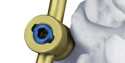
4 Overview Two step locking mechanism Initial locking with locking cap designed for secure positiong of rod whilst screw heads remain mobile Final locking of construct with blue set screw designed for unconstrained locking without cross threading Click X Standard (Polyaxial with click-on head) Click-on mechanism for enhanced field visualisation during segment preparation Polyaxial head for case specific manipulation Intra-Op Post-Op Dual core screw (with double thread) Designed for rapid insertion and secure anchorage in both, cortical and cancellous bone Click X Standard Polyaxial Screws Cylindrical zone with cortical bone thread profile Short conical transition zone enhances pull-out strength Cylindrical zone with cancellous bone thread profile Threaded, round tip designed for immediate bone grip 2 DePuy Synthes Click X System Surgical Technique


5 Click X Preassembled Preassembled polyaxial screw with reliability and retaining force: Designed to allow controlled reduction of even very rigid spondylolisthesis Click X Monoaxial Rotational Rotatable, preassembled head for ease of positioning and manipulation: Monosegmental instrumentation for Spondylolisthesis reduction Multi-segmental instrumentation as stand alone or in combination with Click X Standard screws Pre-Op Post-Op Spondylolisthesis correction with Click X Preassembled Pre-Op Post-Op. Click X preassembled and Click X monoaxial rotational screws used in the slipped vertebrae for Spondy lolisthesis correction in the lumbar region Click X Preassembled Screws Click X Monoaxial Rotational Screws Click X System Surgical Technique DePuy Synthes 3
6 AO Spine Principles The four principles to be considered as the foundation for proper spine patient management underpin the design and delivery of the Curriculum: Stability Alignment Biology Function. 1,2 Stability Stabilization to achieve a specific therapeutic outcome axial sagittal coronal Alignment Balancing the spine in three dimensions Biology Etiology, pathogenesis, neural protection, and tissue healing Function Preservations and restoration of function to prevent disability Copyright 2012 by AOSpine 1 Aebi M, Arlet V, Webb JK, (2007): AOSPINE Manual (2 vols), Stuttgart, New York: Thieme. 2 Aebi M, Thalgott JS, Webb JK (1998): AO ASIF Principles in Spine Surgery. Berlin: Springer. 1 DePuy Synthes Click X System Surgical Technique
7 Indications and Contraindications Intended use The Click X system is a posterior thoracolumbar pedicle screw system intended to provide precise and segmental stabilization of the spine in skeletally mature patients. Indications General indications The implants can be used for the following indications in the area of the lower thoracic and lumbar spine Degenerative instabilities Instabilities following decompression Type A1 fractures and related types of the B and C group Type A2 and A3 fractures as well as similar fractures of the C group, if combined with an anterior intervention Tumors without anterior defect Indications Spondylolisthesis Spondylolisthesis in the lumbar region Notes: An anterior release is recommended for spondylolisthesis greater than grade I. An anterior release is essential for spondylolisthesis greater than grade II. A 360 fixation is recommended particularly after a major reduction. 1 Contraindications Deformities In fractures and tumors with severe anterior vertebral body disruption, an additional anterior support or column reconstruction is required. Osteoporosis 1 Aebi M., Thalgott J.S., Webb J.K. (1998): AO ASIF Principles in Spine Surgery, Springer Verlag, Berlin, Chap , p. 102 sq. Click X System Surgical Technique DePuy Synthes 5

8 Implants 1. Screws Click X Standard, pedicle screw with dual core and click-on head, titanium alloy TAN (Ti Al6 Nb7) Art. No. B Lengths Colour mm mm violet mm mm dark blue mm mm green mm mm pink mm mm turquoise 3-D head for Click X Standard pedicle screw Art. No. Material TAN Click X Preassembled, pedicle screw with dual core, titanium alloy TAN (Ti Al6 Nb7) Art. No. B Lengths Colour mm mm violet mm mm dark blue , 7.0 mm mm green mm mm pink mm mm turquoise Click X Monoaxial Rotational, pedicle screw with dual core Available in TAV (Ti Al6 V4) only Art. No. B Lengths Colour V 507V 5.5 mm mm gold V 517V 6.2 mm mm blue V 527V 7.0 mm mm green Click X locking cap Art. No. Material Drive TAN 3.5 mm hexagonal TAN Stardrive T25 6 DePuy Synthes Click X System Surgical Technique
 Art. No. Colour 498.813 dark blue Cross-link, rod B 3.5 mm, titanium alloy (TAN) Art. No. Length 496.")
9 2. Rods Click X rod, curved, normalized, pure titanium Art. No. B Lengths mm mm USS rod, soft, pure titanium Art. No. B Lengths mm mm 3. Transverse Connectors Cross-link clamp, for rods B 6 mm, preassembled, titanium alloy (TAN) Art. No. Colour dark blue Cross-link, rod B 3.5 mm, titanium alloy (TAN) Art. No. Length mm mm mm mm mm Click X System Surgical Technique DePuy Synthes 7
10 Instruments Instruments for pedicle preparation Pedicle Awl B 4.0 mm with Canevasit Handle, for Pedicle Screws B 5.0 to 7.0 mm or Pedicle Awl B 4.0 mm with Silicone Handle, length 255 mm, for Pedicle Screws B 5.0 to 7.0 mm Pedicle Awl B 3.0 mm, length 230 mm, for Screws B 4.0 and 4.2 mm Pedicle Awl B 4.2 mm with Silicone handle, for pedicle screws B 8.0 and 9.0 mm /546 Feeler for Screw Channel, B 2.3 mm, length 275 mm, straight/curved Length Indicator for Pedicle Screws range to 110 mm or Length Indicator for Pedicle Screws B 4.2 to 9.0 mm Tap for Pedicle screws B mm with dual core, length 230/35 mm Burr for Pedicle Screw Click X Standard Reamer for preassembled Pedicle Screws Pedicle Probe B 3.8 mm with Canevasit Handle, length 230 mm, for Pedicle Screws B 5.0 to 7.0 mm or Pedicle Probe B 3.7 mm with Silicone Handle, length 240 mm, for Pedicle Screws B 5.0 to 7.0 mm or Pedicle Probe with shaft, with Hexagonal Quick Coupling B 6.0 mm Pedicle Probe B 3.8 mm, curved, with Silicone Handle, for Pedicle Screws B 5.0 to 7.0 mm Pedicle Probe B 5.0 mm, with Silicone Handle, length 240 mm, for Pedicle Screws B 8.0 and 9.0 mm or Pedicle Probe B 4.8 mm, with Canevasit Handle, length 230 mm, for Pedicle Screws B 8.0 and 9.0 mm 8 DePuy Synthes Click X System Surgical Technique
11 Instruments for screw insertion Screwdriver, hexagonal, B 3.5 mm, with T-Handle or Screwdriver Shaft 3.5 mm, with Hexagonal Quick Coupling 6.0 mm, for Click X Screwdriver Shaft 3.5 mm, long, with Hexagonal Quick Coupling 6.0 mm, for Click X Screwdriver, hexagonal, B 3.5 mm with T-Handle, for Pedicle Screws Click X preassembled Screwdriver Shaft 3.5 mm, long, with Hexagonal Quick Coupling 6.0 mm, for preassembled Click X Pedicle Screws or Screwdriver Shaft 3.5 mm, short, with Hexagonal Quick Coupling 6.0 mm, for preassembled Click X Pedicle Screws with Holding Sleeve, long, for No or Holding Sleeve, short, for No with Outer Sleeve for No Holding Sleeve for Pedicle Screws Click X Monoaxial, rotational Instruments for rod insertion Bending Template B 6.0 mm, length 150 mm or Bending Template B 6.0 mm, length 150 mm, single use Bending Pliers with Rolls for Rods B 6.0 mm, length 300 mm or Bending Pliers with Rolls for USS Rods B 5.0 mm, with Radius Adjustment Holding Forceps, straight, with Scissors Grip, for Rods B 6.0 mm Holding Forceps, angled, with Scissors Grip, for Rods B 6.0 mm /374 Holding Forceps with narrow tip, straight, length 300 mm, for Rods B 6.0 mm Holding Forceps with broad Tip, length 290 mm, for Rods B 6.0 mm Rod Pusher for Rods B 6.0 mm Rod Pusher for Click X Rod Pusher for Click X, long Holding Sleeve for Pedicle Screws Click X preassembled Holding Sleeve for Pedicle Screws Click X preassembled, for No Holding Sleeve with Locking, for Pedicle Screws Click X Standard Positioning Holder for Click X 3-D Head, with Disconnecting Device Click X System Surgical Technique DePuy Synthes 9
12 Instruments Instruments for locking cap insertion (hexagonal and Stardrive) Screwdriver for Click X Locking Cap, self-holding, with T-Handle or Screwdriver for Click X Locking Cap, self-holding, long, with T-Handle Screwdriver for Click X Locking Cap, self-holding, long, with Knurled Handle or Screwdriver for Click X Locking Cap, self-holding, with Knurled Handle Instruments for locking cap insertion (Stardrive) Locking Cap Driver with T-Handle, for Pangea with Screwdriver Shaft Stardrive, T25, with Hexagonal Coupling 6.0 mm Instruments for distraction and compression Spreader Forceps for Pedicle Screws, length 330 mm Distractor, adjustable, with short feet, length 320 mm, for Pedicle Screws Click X Standard Distractor, adjustable, with long feet, length 320 mm, for preassembled Pedicle Screws Instruments for Spondylolisthesis reduction Click X Reduction Instrument for Spondylolisthesis Removal instruments for damaged screw sockets Extraction Pliers for Click X Centering sleeve for Rod Pusher for Click X Extraction Screw, conical, cannulated, for ClickX preassembled T-Handle, cannulated, for Extraction Screw for Click X Extraction Screw, conical, for Click X Kirschner Wire B 2.0 mm with trocar tip, length 150 mm, Titanium Alloy (TAV) Vice Grip, length 180 mm Removal instruments for locking caps Extractor, with L-Handle, for damaged Click X Locking Caps Sleeve with L-Handle, for Extractor No Ratchet Wrench for Nut, hexagonal, 11.0 mm Compression Forceps, length 360 mm, for Pedicle Screws or Compression Forceps, length 335 mm, for Pedicle Screws 11 DePuy Synthes Click X System Surgical Technique
13 General Surgical Technique Required instrument sets Click X Basic Instrument Set in Vario Case Optional instrument sets Instrument Set for Pedicle Preparation Set, in Vario Case 1. Open and prepare pedicles a. Open pedicles and determine screw length Pedicle Awl B 4.0 mm with Silicone Handle, length 255 mm, for Pedicle Screws B 5.0 to 7.0 mm Pedicle Probe B 3.7 mm with Silicone Handle, length 240 mm, for Pedicle Screws B 5.0 to 7.0 mm Note: Use image intensifier control to confirm instrument position. Click X System Surgical Technique DePuy Synthes 11

14 General Surgical Technique Optional instruments Pedicle Probe B 3.8 mm, curved, with Silicone Handle, length 290 mm, for Pedicle Screws B 5.0 to 7.0 mm Pedicle Awl B 3.0 mm, length 230 mm, for Screws B 4.0 and 4.2 mm Pedicle Awl B 4.2 mm with Silicone Handle, length 255 mm, for Pedicle Screws B 8.0 and 9.0 mm Pedicle Probe B 5.0 mm with Silicone Handle, length 240 mm, for Pedicle Screws B 8.0 and 9.0 mm Locate pedicles as described in AO ASIF Principles in Spine Surgery. Use a Pedicle Awl to open the cortex of the pedicles (to a depth of 10 mm). Continue opening the pedicles using a Pedicle Probe with markings at 30, 40 and 50 mm and determine the length of the Click X pedicle screws. Note: For correct fit of pedicle screws check diameter of Pedicle Awl and Pedicle Probe and corresponding screw size. 11 DePuy Synthes Click X System Surgical Technique
15 b. Measure screw channel (optional) /546 Feeler for Screw Channel, B 2.3 mm, length 275 mm, straight/curved Optional instruments Length Indicator for Pedicle Screws range to 110 mm Measure the pedicle screw channel to determine the length of the pedicle screw with a Feeler for Screw Channel and make sure there are no perforations. Note: Use image intensifier control to confirm instrument position. Click X System Surgical Technique DePuy Synthes 11
16 General Surgical Technique c. Tapping (optional) All Click X screws are self-tapping, therefore it is not necessary to tap the pedicles. However, if tapping is preferred, use the appropriate size tap with tap handle. Required instrument sets Instrument Set for Pedicle Preparation Set, in Vario Case with Tap for Pedicle Screws with dual core Use the pedicle preparation set with the corresponding inserts for taps. Choose the tap according to screw type and size. Follow the appropriate technique for screw insertion: Click X Standard pedicle screws (step 2.1) Click X Preassembled pedicle screws (step 2.2) Click X Monoaxial Rotational pedicle screws (step 2.3) 11 DePuy Synthes Click X System Surgical Technique
17 2.1. Insert Click X Standard pedicle screws a. Insert Click X Standard pedicle screw Screwdriver Shaft 3.5 mm, with Hexagonal Quick Coupling 6.0 mm, for Click X with Ratchet Wrench with T-Handle, with Hexagonal Quick Coupling 6.0 mm Holding Sleeve with Locking, for Pedicle Screws Click X Standard Optional instruments Screwdriver Shaft 3.5 mm, long, with Hexagonal Quick Coupling 6.0 mm, for Click X Attach the Holding Sleeve to a B 3.5 mm Hexagonal Screwdriver, ensuring that the Holding Sleeve is open to the red line. Load a Click X Standard screw on the screwdriver assembly. Slide the Holding Sleeve over the head of the screw, and close the Holding Sleeve by rotating the knurled sleeve in the direction of the close arrow. Insert the screw into the prepared pedicle. Repeat for each screw. Click X System Surgical Technique DePuy Synthes 11

. Insert the Distraction Forceps in closed position between both screws.")
18 General Surgical Technique Optional If desired, posterior interbody fusion may be performed at this time. Independent placement of the screws allows improved visualisation and access to the disc space Distractor, adjustable, with short feet, length 320 mm, for Pedicle Screws Click X Standard For interbody fusion, the use of Distraction Forceps facilitates the procedure (PLIF or T-PLIF). Insert the Distraction Forceps in closed position between both screws. Slowly open the Distraction Forceps while guiding the tips beneath the screw heads. After interbody fusion procedure is completed remove instrument. 11 DePuy Synthes Click X System Surgical Technique

19 b. Prepare site for 3-D head Burr for Pedicle Screw Click X Standard Place the Reamer over the Click X Standard pedicle screw. Prepare the surrounding bone for the 3-D head, using rotating movements with the tilted reamer until any interfering bone has been removed. Proper reaming will ensure that enough space is created around the 3-D head of the pedicle screw. This allows the head to align properly and enables stressfree instrumentation. Repeat for each pedicle screw. Note: Care should be taken when reaming the most superior (and inferior) level to maintain and protect the non-fused facet joints. Click X System Surgical Technique DePuy Synthes 11


20 General Surgical Technique c. Attach 3-D head Positioning Holder for Click X 3-D Head with Disconnecting Device Using the Positioning Holder, pick up a Click X 3-D Head from the implant rack. Press or click the 3-D head securely over the Click X Standard pedicle screw. Press the button at the distal end of the instrument to push down the fuchsia conical element and release the 3-D head. The 3-D head is still polyaxial at this time. Note: If deeper insertion of the pedicle screw with attached 3-D head is required, make sure the 3-D head is not touching the bone surface as this will limit its polyaxial freedom and could lead to disengagement of the 3-D head. Note: Prior to loading the 3-D head onto the Positioning Holder, verify that the fuchsia conical element in the 3-D head is not pressed down. If it is pressed down, it must be lifted in its upper position using the Extraction Pliers ( ) as described on page 40. Follow the appropriate technique for rod insertion: Insert rods (step 3 on page 25). Correct Incorrect 11 DePuy Synthes Click X System Surgical Technique
21 2.2. Insert Click X Preassembled pedicle screws a. Prepare site for 3-D head Reamer for preassembled Pedicle Screws Insert the tip of the Reamer into the probed hole. Prepare the surrounding bone for free mobility of the 3-D head, using rotating movements with the tilted Reamer until any interfering bone has been removed. Repeat for each pedicle. Note: Care should be taken when reaming the most superior (and inferior) level to maintain and protect the non-fused facet joints. Click X System Surgical Technique DePuy Synthes 11
22 General Surgical Technique b. Insert Click X Preassembled pedicle screws Screwdriver Shaft 3.5 mm, with Hexagonal Quick Coupling 6.0 mm, for Click X with Ratchet Wrench with T-Handle, with Hexagonal Quick Coupling 6.0 mm Holding Sleeve for Pedicle Screws Click X preassembled Optional instruments Screwdriver Shaft 3.5 mm, long, with Hexagonal Quick Coupling 6.0 mm, for preassembled Click X pedicle screws with Holding Sleeve, long, for No and Outer Sleeve for No Position the assembly of Screwdriver for 3.5 mm Hexagonal Socket and Holding Sleeve for Click X Preassembled on the 3-D head and pick up a screw from the rack. Assure the Holding Sleeve is properly fitting in the 3-D head and that it is firmly tightened. Insert the Click X Preassembled pedicle screw into the prepared pedicle and withdraw the Holding Sleeve from the screw. Repeat for each screw. 22 DePuy Synthes Click X System Surgical Technique


23 Optional If desired, posterior interbody fusion may be performed at this time Distractor, adjustable, with long feet, length 320 mm, for preassembled Pedicle Screws For interbody fusion, the use of Distraction Forceps facilitates the procedure (PLIF or T-PLIF). Insert the Distraction Forceps in closed position between both screws. Slowly open the Distraction Forceps while guiding the tips beneath the screw heads. After interbody fusion procedure is completed remove instrument. Follow the appropriate technique for rod insertion: Insert rods (step 3 on page 25). Click X System Surgical Technique DePuy Synthes 22

24 General Surgical Technique 2.3. Insert Click X Monoaxial Rotational pedicle screws a. Prepare site for rotational head Reamer for preassembled Pedicle Screws Insert the tip of the Reamer into the probed hole. Prepare the surrounding bone for free mobility of the rotational head, using rotating movements with the tilted Reamer until any interfering bone has been removed. Repeat for each pedicle screw. Note: Care should be taken when reaming the most superior (and inferior) level to maintain and protect the non-fused facet joints. 22 DePuy Synthes Click X System Surgical Technique
25 b. Insert Click X Monoaxial Rotational pedicle screw Screwdriver Shaft 3.5 mm, with Hexagonal Quick Coupling 6.0 mm, for Click X with Ratchet Wrench with T-Handle, with Hexagonal Quick Coupling 6.0 mm Holding Sleeve for Click X Monoaxial, rotational Position the assembly of Screwdriver for 3.5 mm Hexagonal Socket and the Holding Sleeve for Click X Mono axial Rotational on the 3-D head and pick up a screw from the rack. Assure the Holding Sleeve is properly fitting in the rotational 3-D head and that it is firmly tightened. Insert the screw into the prepared pedicle and withdraw the Holding Sleeve from the screw. Repeat for each screw. Click X System Surgical Technique DePuy Synthes 22


26 General Surgical Technique Optional If desired, posterior interbody fusion may be performed at this time Distractor, adjustable, with long feet, length 320 mm, for preassembled Pedicle Screws For interbody fusion, the use of Distraction Forceps facilitates the procedure (PLIF or T-PLIF). Insert the Distraction Forceps in closed position between both screws. Slowly open the Distraction Forceps while guiding the tips beneath the screw heads. After interbody fusion procedure is completed remove instrument. Follow the appropriate technique for rod insertion: Insert rods (step 3 on page 25). 22 DePuy Synthes Click X System Surgical Technique

27 3. Insert rods a. Select and prepare rod Trial Rod B 6.0 mm, length 150 mm Bending Pliers with Rolls for USS Rods B 5.0 mm, with Radius Adjustment Determine the appropriate rod contour and length using the Bending Template. The polyaxial mobility of the 3-D head compensates for some lateral screw offset (except Click X Monoaxial Rotational pedicle screws). Select the appropriate length and, if necessary, bend the rod using Bending Pliers. Note: Titanium rods must not be bent back and forth. Repeated bending can weaken the rod. b. Insert rod / Holding Forceps, straight, with Scissors Grip, for Rods B 6.0 mm Insert the rod into the 3-D or rotational head using Rod Holding Forceps. Note: Before inserting a rod, ensure each of the 3D heads can move freely. If there is limited polyaxial movement, back out the screw assembly by turning counterclockwise until full range of motion is obtained. Click X System Surgical Technique DePuy Synthes 22

28 General Surgical Technique c. Push rod into 3-D head Rod Pusher for Click X Optional instruments Rod Pusher for Rods B 6.0 mm Rod Pusher for Click X, long Using a Rod Pusher, push the rod firmly into the 3-D or rotational head. For constructs with two or more levels, it is recommended to begin with the central 3-D head. 22 DePuy Synthes Click X System Surgical Technique

29 4. Attach locking caps Screwdriver for Click X Locking Cap, self-holding, with Knurled Handle Rod Pusher for Click X Optional instruments Screwdriver for Click X Locking Cap, self-holding, long, with Knurled Handle Rod Pusher for Click X, long Using a Screwdriver for Click X Locking Cap, pick up a locking cap from the implant rack. Ensure the screwdriver tongs fit firmly into the slots of the locking cap. With the Rod Pusher in place, insert the Locking Cap and finger tighten with thumb and forefinger to capture the rod within the head. The head will retain its polyaxial resp. rotatable mobility. Note: Use of the Rod Pusher ensures correct alignment and reduces cross-threading of the locking cap. Repeat for the remaining pedicle screws, ensuring that all locking caps are attached. Click X System Surgical Technique DePuy Synthes 22
30 General Surgical Technique 5. Compress or distract Compression and distraction can be applied in two different modes: a. Lordotic manipulation: With mobile polyaxial 3-D heads the angle of the pedicle screws and the rod is variable. The trapezium shaped disc space between the vertebral bodies may be compressed or distracted at the posterior end only to reposition the curvature of the lumbar spine. LORDODIC LORDODIC COMPRESSION Note: With Click X Monoaxial Rotational pedicle screws lordotic compression is not possible as polyaxial head movement is not possible. The heads will not align to the rod and might not be locked properly. b. Parallel manipulation: With fixed 3-D resp. rotational heads the angle of the pedicle screw and the rod is fixed. The trapezium shaped disc space between the vertebral bodies may be compressed or distracted with a linear load distribution over the endplates to reposition the height of a motion segment. PARALLEL PARALLEL COMPRESSION Locked Unlocked 22 DePuy Synthes Click X System Surgical Technique

31 a. Lordotic manipulation: Compress or distract with mobile 3-D heads to reposition curvature Compression Forceps, length 335 mm, for Pedicle Screws Spreader Forceps for Pedicle Screws, length 330 mm Screwdriver for Click X Locking Cap, self-holding, with T-Handle Screwdriver Shaft 3.5 mm, with Hexagonal Quick Coupling 6.0 mm, for Click X with Ratchet Wrench with T-Handle, with Hexagonal Quick Coupling 6.0 mm Rod Pusher for Click X Compression Optional instruments Screwdriver for Click X Locking Cap, self-holding, long, with T-Handle Screwdriver Shaft 3.5 mm, long, with Hexagonal Quick Coupling 6.0 mm, for Click X Rod Pusher for Click X, long Use Compression Forceps to achieve compression, or Distraction Forceps to achieve distraction. Once the desired compression or distraction is achieved, keep it and simultaneously tighten the blue set screws by inserting a Screwdriver for 3.5 mm Hexagonal Socket through the Rod Pusher, using the Rod Pusher as countertorque. Repeat for each level. Note: Compression or distraction with mobile 3-D heads is only possible if the blue set screw of the locking caps has not been tightened yet. Click X System Surgical Technique DePuy Synthes 22

32 General Surgical Technique b. Parallel manipulation: Compress or distract with fixed 3-D heads to reposition height of disc space Compression Forceps, length 335 mm, for Pedicle Screws Spreader Forceps for Pedicle Screws, length 330 mm Screwdriver for Click X Locking Cap, self-holding, with T-Handle Screwdriver Shaft 3.5 mm, with Hexagonal Quick Coupling 6.0 mm, for Click X with Ratchet Wrench with T-Handle, with Hexagonal Quick Coupling 6.0 mm Rod Pusher for Click X Distraction Optional instruments Screwdriver for Click X Locking Cap, self-holding, long, with T-Handle Screwdriver Shaft 3.5 mm, long, with Hexagonal Quick Coupling 6.0 mm, for Click X Rod Pusher for Click X, long Restore proper lordosis, then place a Screwdriver for 3.5 mm Hexagonal Socket through the Rod Pusher. Tighten the blue set screw while using the Rod Pusher as countertorque. Repeat for each screw. Place the Screwdriver for Click X locking cap through the Rod Pusher and onto the assembly, inserting the prongs into the locking cap. Insert a 3.5 mm Hexagonal Socket through the shaft of the Screwdriver for Click X locking caps. 33 DePuy Synthes Click X System Surgical Technique
33 Loosen the locking cap set screw while counteracting torque with both the Rod Pusher and the locking cap screwdriver. This will prevent the locking cap from loosening. Use Compression Forceps to achieve compression or Distraction Forceps to achieve distraction. Once the desired compression or distraction is achieved, keep it and simultaneously retighten the blue set screws with a 3.5 mm Hexagonal Screwdriver. Click X System Surgical Technique DePuy Synthes 33

34 General Surgical Technique 6. Final tightening Screwdriver Shaft 3.5 mm, with Hexagonal Quick Coupling 6.0 mm, for Click X Rod Pusher for Click X Optional instruments Screwdriver Shaft 3.5 mm, long, with Hexagonal Quick Coupling 6.0 mm, for Click X Rod Pusher for Click X, long Place the Rod Pusher over the 3-D resp. rotational head. Using a 3.5 mm Hexagonal Screwdriver, thighten the set screw until the audible screeching noise, which windicates the proper locking of the assembly. Repeat for all locking caps. Optional If desired, a torque-limiting handle may be used. Attach a screwdriver shaft to the handle and tighten until the audible click noise. Optional If desired, transverse connectors may be added. They are intended to stabilize the construct and increase stability. 33 DePuy Synthes Click X System Surgical Technique


35 Surgical Technique for Spondylolisthesis Reduction Required instrument sets Click X Basic Instrument Set in Vario Case Click X Reduction Instruments for Spondylolisthesis in Vario Case Optional instrument sets Instrument Set for Pedicle Preparation Set, in Vario Case Spondylolisthesis reduction can be achieved using the Click X Spondylolisthesis Reduction Instruments. For pedicle screw placement refer to the surgical technique described earlier in this brochure. For a single level spondylolisthesis reduction two methods are possible: a. Bi-segmental instrumentation All types of Click X screws can be used cranial and caudal to the slipped vertebra. For the slipped vertebra itself, the use of Click X Preassembled pedicle screws is mandatory. b. Mono-segmental instrumentation Since bending strength is limited with all polyaxial pedicle screws, use only Click X Monoaxial Rotational pedicle screws caudal (or cranial) to the slipped vertebra. For the slipped vertebra itself, the use of Click X Preassembled pedicle screws is mandatory. The surgical technique described shows a bi-segmental instrumentation of a spondylolisthesis on L5/S1 with Click X Standard pedicle screws cranial and caudal to the slipped vertebrae. Click X System Surgical Technique DePuy Synthes 33

36 Surgical Technique for Spondylolisthesis Reduction 1. Insert Click X screws Follow steps 1 and 2 described in the surgical technique for Click X screws. Insert Click X Standard, Preassembled or Monoaxial Rotational pedicle screws in the adjacent vertebrae. Insert Click X Preassembled pedicle screws into the affected level. Note: Care should be taken when reaming the most superior (and inferior) level to maintain and protect the non-fused facet joints. 2. Insert rods Follow step 3 described in the surgical technique for Click X screws Select the appropriate rod length and insert into the 3-D heads. Place locking caps in the 3-D heads of the cranial and caudal vertebrae. Tighten the caudal set screws only. This will prevent the slippage of the rod during the subsequent reduction. Note: The Click X Preassembled pedicle screws are pulled right up to the rod during reduction. The reduction track is determined by the curve of the rod and the position resp. insertion depth of the screws. 33 DePuy Synthes Click X System Surgical Technique


37 3. Apply reduction instruments a. Attach reduction instruments Click X Reduction Instrument for Spondylolisthesis Check that the black nut on each Reduction Instrument is near the handle of the instrument. Place reduction instruments bilaterally on the 3-D heads in the level to be reduced. Slide the guiding tubes down the rods, ensuring that the 3-D heads are engaged. b. Reduce vertebral body Click X Reduction Instrument for Spondylolisthesis Rotate the nuts on each instrument simultaneously in clockwise direction to grad ually pull each screw to the rod. Once the red line appears on the thread, the rod is fully seated in the 3-D head. Note: Distraction between L5/S1 or L4/L5 may be required prior to reduction. Please refer to step 2.2 described in the general surgical technique for Click X screws. Click X System Surgical Technique DePuy Synthes 33

38 Surgical Technique for Spondylolisthesis Reduction 4. Assemble construct a. Attach locking caps on remaining 3-D heads Screwdriver for Click X Locking Cap, self-holding, long, with Knurled Handle Click X Reduction Instrument for Spondylolisthesis Remove the inner tube of the Reduction Instruments. Use the long Screwdriver for Click X Locking Cap to insert the locking caps. Finger tighten with thumb and fore finger each locking cap while applying counter torque with the Reduction Instrument. b. Remove reduction instruments Fully unscrew the black nuts on both Reduction Instruments, push the guiding tubes upwards and remove the instruments. 33 DePuy Synthes Click X System Surgical Technique
39 5. Compress or distract Follow step 5 described in the general surgical technique for Click X screws Compression and distraction can be applied in two different modes: a. Lordotic manipulation: With mobile polyaxial 3-D Heads the angle of the pedicle screws and the rod is variable. The trapezium shaped disc space between the vertebral bodies may be compressed or distracted at the posterior end only to reposition the curvature of the lumbar spine. LORDODIC LORDODIC COMPRESSION Note: With Click X Monoaxial Rotational pedicle screws lordotic compression is not possible as polyaxial head movement is not possible. The heads will not allign to the rod and might not be locked properly. PARALLEL PARALLEL COMPRESSION b. Parallel manipulation: With fixed 3-D resp. rotational heads the angle of the pedicle screw and the rod is fixed. The trapezium shaped disc space between the vertebral bodies may be compressed or distracted with a linear load distribution over the endplates to reposition the height of a motion segment. Locked Unlocked Click X System Surgical Technique DePuy Synthes 33
40 Surgical Technique for Spondylolisthesis Reduction 6. Apply final tightening Follow step 6 described in the general surgical technique for Click X screws. Optional If desired, transconnectors may be added. They are intended to stabilize the construct and increase stability. 33 DePuy Synthes Click X System Surgical Technique

41 Remobilization and Removal of Undamaged Click X Implants Required instrument sets Click X Basic Instrument Set in Vario Case or Instrument Set for Removal of Click X Implants in Vario Case 1. Removal of Click X Locking Cap Screwdriver, hexagonal, B 3.5 mm, with T-Handle Rod Pusher for Click X Centering Sleeve for Rod Pusher for Click X Place the Rod Pusher over the 3-D head. Use the assembly of Rod Pusher, Centering Sleeve and Screwdriver to loosen the blue set screw of the locking cap while counteracting torque with the Rod Pusher. Note: Never use a self-holding Screwdriver for Click X Locking Cap (e.g ) to loosen or remove the locking caps. Click X System Surgical Technique DePuy Synthes 33

, remove it by toggling the head while pulling.")
42 Remobilization and Removal of Undamaged Click X Implants 2. Remobilization of Click X 3-D head Extraction Pliers for Click X Remove the rod. The 3-D head has to be remobilized with the Extraction Pliers. Introduce the pliers deeply into the head and compress the handle. Check if the 3-D head is mobile. 3.1 Removal of Click X Standard pedicle screw Screwdriver, hexagonal, B 3.5 mm, with T-Handle Holding Sleeve for Click X Standard pedicle screws After remobilizing the 3-D head (steps 1 and 2), remove it by toggling the head while pulling. Use the assembly of Holding Sleeve for Click X Standard screws and Screwdriver. Close the Holding Sleeve, assure firm locking and remove the Click X Standard pedicle screw. Note: Do not reuse removed 3-D heads. 44 DePuy Synthes Click X System Surgical Technique
43 3.2. Removal of Click X Preassembled pedicle screw Screwdriver, hexagonal, B 3.5 mm, with T-Handle Holding Sleeve for Pedicle Screws Click X preassembled After remobilizing the 3-D head (steps 1 and 2) use the assembly of Holding Sleeve for Click X Preassembled screws and Screwdriver. Close the Holding Sleeve, assure firm locking and remove the Click X Preassembled pedicle screw. Click X System Surgical Technique DePuy Synthes 44

44 Remobilization and Removal of Undamaged Click X Implants 3.3. Removal of Click X Monoaxial Rotational pedicle screw Screwdriver, hexagonal, B 3.5 mm, with T-Handle Holding Sleeve for Pedicle Screws Click X Monoaxial, rotational Remove locking cap and rod. Use the assembly of Holding Sleeve for Click X Monoaxial Rotational screws and Screwdriver. Assure firm locking of the Holding Sleeve and remove the Click X Monoaxial Rotational pedicle screw. 44 DePuy Synthes Click X System Surgical Technique

45 Removal of Click X Implants with Damaged Hexagonal Socket Required instrument sets Instrument Set for Removal of Click X Implants in Vario Case Note: Click X removal with the help of an extraction screw is only applicable on screws with damaged hexagonal sockets. For screws with intact hexagonal sockets, use the standard screwdrivers (see preceding part) Removal of Click X Locking Cap with damaged hex socket using an extraction screw Rod Pusher for Click X Centering Sleeve for Rod Pusher for Click X T-Handle, cannulated, for Extraction Screw for Click X Extraction Screw, conical, for Click X Put the Rod Pusher over the Click X head and make sure that it is aligned over the head (if not remove disturbing structures around the head). Insert the Centering Sleeve with red marking into the Rod Pusher. Mount the Extraction Screw with red marking on the T-Handle and introduce the assembly through the Centering Sleeve. Click X System Surgical Technique DePuy Synthes 44


46 Removal of Click X Implants with Damaged Hexagonal Socket Turn the handle counter-clockwise to secure the Extraction Screw in the damaged socket of the locking cap set screw. Counteract torque with the Rod Pusher. Continue turning to loosen the blue set screw and go on until the locking cap is removed. Notes: Never use a self holding Screwdriver for Click X Locking Cap (e.g ) to loosen or remove the locking caps. Only the Extraction Screw with red marking is intended for the removal of locking caps, never use the Cannulated Extraction Screw. 44 DePuy Synthes Click X System Surgical Technique


47 1.2. Removal of Click X Locking Cap with damaged hex socket using locking cap removal tools Required instrument sets Extraction Instrument Set for Damaged Click X Locking Caps, in Vario Case Extractor, with L-Handle, for damaged Click X Locking Caps Sleeve, with L-Handle, for Extractor No Ratchet Wrench for Nut, hexagonal, 11.0 mm Note: The locking cap removal tools can be used to remove the locking cap from a Click X assembly. They are used in revision surgery in which the blue locking cap set screw has been damaged. These tools damage the 3-D heads. After removing the locking cap, the Click X screws and 3-D heads must be replaced. Insert the Extractor, with L-Handle, for damaged Click X Locking Caps through the Sleeve with L-Handle. Place the distal end of the extractor on the locking cap and slide the sleeve down over the rod. Hand-tighten the nut of the extractor. Place the Ratchet Wrench on the 11 mm nut so that the word ON is visible on the body of the wrench. Use the Ratchet Wrench to tighten the nut. While holding the Sleeve with L-Handle, for Extractor No in place, turn the extractor counterclockwise, until there is no resistance. Remove the extractor and sleeve from the assembly. Remove the locking cap from the extractor. Using the Ratchet Wrench in the OFF position, turn the nut counterclockwise until the cap is released. Click X System Surgical Technique DePuy Synthes 44


48 Removal of Click X Implants with Damaged Hexagonal Socket 2.1. Removal of Click X Standard pedicle screw with damaged hex socket Holding Sleeve with Locking, for Pedicle Screws Click X Standard T-Handle, cannulated, for Extraction Screw for Click X Extraction Screw, conical, for Click X Vice Grip, length 180 mm Assure that the 3-D head is remobilized as described in step 2 on page 40. Remove the 3-D head by toggling sideways and pulling upwards, either by hand or with the vice grip. Assemble the Holding Sleeve, the T-Handle and the Extraction Screw with red marking. Place the Holding Sleeve over the Click X Standard pedicle screw and close it by assuring firm locking. If the Holding Sleeve fails to align the assembly, remove disturbing bone structure. Turn the T-Handle counter-clockwise to secure the Extraction Screw in the damaged socket. Continue turning to remove the pedicle screw. 44 DePuy Synthes Click X System Surgical Technique

49 2.2 Removal of Click X Preassembled pedicle screw with damaged hex socket Kirschner Wire B 2.0mm with trocar tip, length 150 mm, Titanium Alloy (TAV) Extraction Screw, conical, cannulated, for ClickX preassembled T-Handle, cannulated, for Extraction Screw for Click X Assure that the 3-D head is remobilized as described in step 2 on page 40. Insert the Kirschner wire into the central hole of the hexagonal socket of the Click X Preassembled pedicle screw. Assemble the T-Handle and the Cannulated Extraction Screw. Slide the assembly over the Kirschner wire and turn the T-Handle counter-clockwise to secure the Extraction Screw in the damaged socket. Continue turning to remove the implant. Note: The Kirschner wire must be used to provide proper guidance of the Cannulated Extraction Screw. Click X System Surgical Technique DePuy Synthes 44


50 Removal of Click X Implants with Damaged Hexagonal Socket 2.3. Removal of Click X Monoaxial Rotational pedicle screw with damaged hexagonal socket Holding Sleeve for Pedicle Screws Click X Monoaxial, rotational T-Handle, cannulated, for Extraction Screw for Click X Extraction Screw, conical, for Click X Assemble the Holding Sleeve, the T-Handle and the Extraction Screw with red marking. Place the assembly on the grey monoaxial head and close by assuring firm locking. If the Holding Sleeve does not fit over the head, remove disturbing bone structure. Turn the T-Handle counter-clockwise to secure the Extraction Screw in the damaged hexagonal socket. Continue turning to remove the pedicle screw. 44 DePuy Synthes Click X System Surgical Technique
51 3. Detaching of implants from Extraction Screws Vice Grip, length 180 mm Hold the locking cap firmly with the Vice Grip and turn the Extraction Screw clock-wise (as a normal screw would be tightened). Note: Carefully inspect the thread of the Extraction Screw. Do not reuse if the screw is damaged (see Care and Maintenance of Synthes Instruments ). 4. Failure of Extraction Screw in damaged hex socket S HSS Drill Bit B 3.5 mm for Implant Steel, sterile Power tool with Jacobs chuck If removal with the help of an Extraction Screw fails at first instance, the grip of the Extraction Screw in the damaged hexagonal socket can be enhanced by drilling further into the hexagonal socket with an HSS Drill Bit. Repeat removal step by step with an intact Extraction Screw. Click X System Surgical Technique DePuy Synthes 44
52 Synthes GmbH Eimattstrasse Oberdorf Switzerland Tel: Fax: Not all products are currently available in all markets. This publication is not intended for distribution in the USA. All surgical techniques are available as PDF files at DePuy Synthes Spine, a division of Synthes GmbH All rights reserved DSEM/SPN/0115/0258(2) 08/17
The Versatile Polyaxial Solution for the Universal Spine Systems. USS II Polyaxial. Surgical Technique
 The Versatile Polyaxial Solution for the Universal Spine Systems USS II Polyaxial Surgical Technique Image intensifier control This description alone does not provide sufficient background for direct use
TSLP Thoracolumbar Spine Locking Plate
 Anterior thoracolumbar spine locking plate TSLP Thoracolumbar Spine Locking Plate Surgical Technique Image intensifier control This description alone does not provide sufficient background for direct use
TELEFIX SURGICAL TECHNIQUE. Implant system for the anterior stabilization of the thoracolumbar spine
 TELEFIX Implant system for the anterior stabilization of the thoracolumbar spine Instruments and implants approved by the AO Foundation. This publication is not intended for distribution in the USA. SURGICAL
USS Variable Axis Screw
 USS Variable Axis Screw Polyaxial side-opening pedicle screw Surgical technique Original Instruments and Implants of the Association for the Study of Internal Fixation AO/ASIF USS Variable Axis Screw
CSLP-Cervical Spine Locking Plate
 For anterior, cervical fixation CSLP-Cervical Spine Locking Plate Surgical Technique Image intensifier control This description alone does not provide sufficient background for direct use of DePuy Synthes
USS Variable Axis Screw (VAS) System. For posterior fixation of the lumbar spine.
 System. For posterior fixation of the lumbar spine.") USS Variable Axis Screw (VAS) System. For posterior fixation of the lumbar spine. Technique Guide Instruments and implants approved by the AO Foundation Table of Contents Introduction USS Variable Axis
USS Variable Axis Screw (VAS) System. For posterior fixation of the lumbar spine. Technique Guide Instruments and implants approved by the AO Foundation Table of Contents Introduction USS Variable Axis
USS II ILIO-SACRAL Modular System for Stable Fixation in the Sacrum and Illium
 USS II ILIO-SACRAL Modular System for Stable Fixation in the Sacrum and Illium Instruments and implants approved by the AO Foundation. This publication is not intended for distribution in the USA. TECHNIQUE
ARCH Laminoplasty System
 Dedicated System for Open-door Laminoplasty ARCH Laminoplasty System Surgical Technique Image intensifier control This description alone does not provide sufficient background for direct use of DePuy Synthes
Interbody fusion cage for the transforaminal approach. Travios. Surgical Technique
 Interbody fusion cage for the transforaminal approach Travios Surgical Technique Image intensifier control This description alone does not provide sufficient background for direct use of DePuy Synthes
The vertebral body replacement with ratchet mechanism. Synex. Surgical Technique
 The vertebral body replacement with ratchet mechanism Synex Surgical Technique Image intensifier control This description alone does not provide sufficient background for direct use of DePuy Synthes products.
Handling instructions. USS Low Profile. Thoracolumbar posterior fixation system.
 Handling instructions USS Low Profile. Thoracolumbar posterior fixation system. U Table of contents Introduction Indications and contraindications 3 USS Low Profile implants 4 Handling implants with stick
Augmentable Pedicle Screws for Osteoporotic Bone. Perforated Click X. Surgical Technique
 Augmentable Pedicle Screws for Osteoporotic Bone Perforated Click X Surgical Technique Image intensifier control This description alone does not provide sufficient background for direct use of DePuy Synthes
Technique Guide. Pangea Spine System. Top loading pedicle screw and hook system for posterior stabilization and correction of spinal deformities.
 Technique Guide Pangea Spine System. Top loading pedicle screw and hook system for posterior stabilization and correction of spinal deformities. Table of Contents Introduction Pangea Spine System 4 Dual
VECTRA-T SURGICAL TECHNIQUE. The Translational Anterior Cervical Palate System. This publication is not intended for distribution in the USA.
 VECTRA-T The Translational Anterior Cervical Palate System This publication is not intended for distribution in the USA. SURGICAL TECHNIQUE Image intensifier control This description alone does not provide
MATRIX Spine System Deformity
 A Solution for Simple and Complex Spine Pathology MATRIX Spine System Deformity Surgical Technique Image intensifier control This description alone does not provide sufficient background for direct use
PERFORATED CLICK X Augmentable pedicle screws for osteoporotic bone
 PERFORATED CLICK X Augmentable pedicle screws for osteoporotic bone Instruments and implants approved by the AO Foundation. This publication is not intended for distribution in the USA. SURGICAL TECHNIQUE
Thoracolumbar Spine Locking Plate (TSLP) System. A low-profile plating system for anterior stabilization of the thoracic and lumbar spine.
 System. A low-profile plating system for anterior stabilization of the thoracic and lumbar spine.") Thoracolumbar Spine Locking Plate (TSLP) System. A low-profile plating system for anterior stabilization of the thoracic and lumbar spine. Technique Guide Instruments and implants approved by the AO Foundation
Thoracolumbar Spine Locking Plate (TSLP) System. A low-profile plating system for anterior stabilization of the thoracic and lumbar spine. Technique Guide Instruments and implants approved by the AO Foundation
ARCH Laminoplasty System. Dedicated System for Open-door Laminoplasty.
 ARCH Laminoplasty System. Dedicated System for Open-door Laminoplasty. Surgical Technique This publication is not intended for distribution in the USA. Instruments and implants approved by the AO Foundation.
Contact Fusion Cage. Surgical Technique
 Contact Fusion Cage Surgical Technique Image intensifier control This description alone does not provide sufficient background for direct use of DePuy Synthes products. Instruction by a surgeon experienced
Comprehensive posterior and anterior deformity system with screws and hooks with dual opening USS II. Surgical Technique
 Comprehensive posterior and anterior deformity system with screws and hooks with dual opening USS II Surgical Technique Image intensifier control This description alone does not provide sufficient background
ECD EXPANDABLE CORPECTOMY DEVICE Continuously Expandable Vertebral Body Replacement for Tumour Cases
 ECD EXPANDABLE CORPECTOMY DEVICE Continuously Expandable Vertebral Body Replacement for Tumour Cases Instruments and implants approved by the AO Foundation. This publication is not intended for distribution
Technique Guide. USS Small Stature/Pediatric. A multifaceted deformity system for use in patients of small stature.
 Technique Guide USS Small Stature/Pediatric. A multifaceted deformity system for use in patients of small stature. Image intensifier control Warning This description alone does not provide sufficient background
XRL A modular expandable radiolucent vertebral body replacement system
 XRL A modular expandable radiolucent vertebral body replacement system This publication is not intended for distribution in the USA. SURGICAL TECHNIQUE Table of Contents Introduction XRL 2 AO Spine Principles
Technique Guide. NFlex. Semi-rigid rods for posterior lumbar stabilization.
 Technique Guide NFlex. Semi-rigid rods for posterior lumbar stabilization. Table of Contents Introduction NFlex 2 Indications and Contraindications 4 NFlex Principles 6 Surgical Technique Preoperative
SYNEX The vertebral body replacement with ratchet mechanism
 SYNEX The vertebral body replacement with ratchet mechanism Instruments and implants approved by the AO Foundation. This publication is not intended for distribution in the USA. SURGICAL TECHNIQUE Image
Mandible External Fixator II. Provides treatment for fractures of the maxillofacial area.
 Mandible External Fixator II. Provides treatment for fractures of the maxillofacial area. Technique Guide This publication is not intended for distribution in the USA. Instruments and implants approved
Valencia Pedicle Screw Surgical Technique
 Valencia Pedicle Screw Surgical Technique VALENCIA CIRCUIT TABLE OF CONTENTS Design Rationale Indications for Use Surgical Technique 1. Pedicle Preparation 2. Screw Insertion 3. Rod Placement 4. Locking
EXCELLA ll. Spinal System
 EXCELLA ll Spinal System Excella II Spinal System INDICATIONS FOR USE The Innovasis Excella II Spinal System is intended for use in the non-cervical area of the spine. WARNING: The safety and effectiveness
Thoracolumbar Anterior Compression (TAC) System. Allows distraction, compression, and lateral fixation of the lower thoracic and lumbar spine.
 System. Allows distraction, compression, and lateral fixation of the lower thoracic and lumbar spine.") Thoracolumbar Anterior Compression (TAC) System. Allows distraction, compression, and lateral fixation of the lower thoracic and lumbar spine. Technique Guide Instruments and implants approved by the AO
Thoracolumbar Anterior Compression (TAC) System. Allows distraction, compression, and lateral fixation of the lower thoracic and lumbar spine. Technique Guide Instruments and implants approved by the AO
The CerviFix System. Including the StarLock Components. CerviFix Clamp and Screw. StarLock Clamp and Screw
 The CerviFix System Including the StarLock Components CerviFix Clamp and Screw StarLock Clamp and Screw The CerviFix System The CerviFix System is a comprehensive set of implants, including clamps, screws,
LCP Low Bend Medial Distal Tibia Plates 3.5 mm. Anatomic plates with low profile head for intra- and extraarticular fractures.
 LCP Low Bend Medial Distal Tibia Plates 3.5 mm. Anatomic plates with low profile head for intra- and extraarticular fractures. Surgical Technique This publication is not intended for distribution in the
Technique Guide. Universal Spinal System (USS). Designed to achieve the goals of scoliosis surgery.
. Designed to achieve the goals of scoliosis surgery.") Technique Guide Universal Spinal System (USS). Designed to achieve the goals of scoliosis surgery. Table of Contents Introduction Universal Spinal System 2 AO ASIF Principles of Internal Fixation 3 Indications
Technique Guide Universal Spinal System (USS). Designed to achieve the goals of scoliosis surgery. Table of Contents Introduction Universal Spinal System 2 AO ASIF Principles of Internal Fixation 3 Indications
Dual-Opening USS. For deformity correction.
 Dual-Opening USS. For deformity correction. Technique Guide Instruments and implants approved by the AO Foundation Table of Contents Introduction Dual-Opening USS 2 AO Principles 4 Indications 5 Preoperative
Technique Guide. MATRIX Spine System MIS Instrumentation. The total solution for simple and complex spine pathology.
 Technique Guide MATRIX Spine System MIS Instrumentation. The total solution for simple and complex spine pathology. Table of Contents Introduction MATRIX Spine System MIS Instrumentation 2 AO Principles
MATRIX Spine System Deformity. A posterior pedicle screw, hook, and rod fixation system.
 MATRIX Spine System Deformity. A posterior pedicle screw, hook, and rod fixation system. Technique Guide Instruments and implants approved by the AO Foundation Table of Contents Introduction MATRIX Spine
SynCage-C short. Surgical Technique. This publication is not intended for distribution in the USA.
 SynCage-C short Surgical Technique This publication is not intended for distribution in the USA. Instruments and implants approved by the AO Foundation. Table of contents Implants 2 Indications/contra-indications
USS II Poly Perforated
 Treatment solution for pedicle screws in osteoporotic bone USS II Poly Perforated Surgical Technique Image intensifier control This description alone does not provide sufficient background for direct use
LCP Medial Distal Tibia Plate, without Tab. The Low Profile Anatomic Fixation System with Angular Stability and Optimal Screw Orientation.
 LCP Medial Distal Tibia Plate, without Tab. The Low Profile Anatomic Fixation System with Angular Stability and Optimal Screw Orientation. Technique Guide LCP Small Fragment System Table of Contents Introduction
Click X Surgical Technique
 Surgical Technique Original Instruments and Implants of the Association for the Study of Internal Fixation AO/ASIF Table of contents Indications / Contra-indications 3 Surgical technique 4 Implant removal
Collinear Reduction Clamp
 For minimally invasive fracture reduction Collinear Reduction Clamp Surgical Technique Image intensifier control This description alone does not provide sufficient background for direct use of DePuy Synthes
Technique Guide. ArcoFix. Anterior-only reduction plate.
 Technique Guide ArcoFix. Anterior-only reduction plate. Table of Contents Introduction ArcoFix 2 AO Principles 4 Indications and Contraindications 5 Surgical Technique Preoperative Planning 6 Insert ArcoFix
OBSOLETED. LCP Medial Distal Tibia Plate, without Tab. The Low Profile Anatomic Fixation System with Angular Stability and Optimal Screw Orientation.
 LCP Medial Distal Tibia Plate, without Tab. The Low Profile Anatomic Fixation System with Angular Stability and Optimal Screw Orientation. Surgical Technique LCP Small Fragment System This publication
MATRIX Spine System Degenerative. A posterior pedicle screw and rod fixation system.
 MATRIX Spine System Degenerative. A posterior pedicle screw and rod fixation system. Technique Guide Instruments and implants approved by the AO Foundation Table of Contents Introduction MATRIX Spine
L8 Spine System SURGICAL TECHNIQUE. Add: No.1-8, Tianshan Road, Xinbei District, Changzhou, Jiangsu, China
 Add: No.-8, Tianshan Road, Xinbei District, Changzhou, Jiangsu, China 23022 Tel: 0086 59 8595556 Fax: 0086 59 859555 Http://www.kanghui.com Add: F25, Shanghai International Pharmaceutical Trad & Exhibition
LCP DISTAL TIBIA PLATE
 LCP DISTAL TIBIA PLATE Instruments and implants approved by the AO Foundation. This publication is not intended for distribution in the USA. SURGICAL TECHNIQUE Image intensifier control This description
Mini External Fixator.
 Mini External Fixator. Assembly and Surgical Technique This publication is not intended for distribution in the USA. Instruments and implants approved by the AO Foundation. Image intensifier control Warning
CERVIFIX Modular tension band system for posterior fixation of the occipito cervical spine, upper and lower cervical spine, and upper thoracic spine
 CERVIFIX Modular tension band system for posterior fixation of the occipito cervical spine, upper and lower cervical spine, and upper thoracic spine PRODUCT OBSOLETED 30th June 2017 DSEM/SPN/1215/0387(1)
PROXIMAL FEMORAL NAIL REMOVAL SET
 PROXIMAL FEMORAL NAIL REMOVAL SET for PFN, TFN and PFNA/PFNA-II Instruments and Implants approved by the AO Foundation. This publication is not intended for distribution in the USA. SURGICAL TECHNIQUE
Replacement Device A modular expandable radiolucent vertebral body replacement system
 XRL Vertebral Body Replacement Device A modular expandable radiolucent vertebral body replacement system SURGICAL TECHNIQUE TABLE OF CONTENTS Introduction XRL System 2 AO Principles 5 Indications and Contraindications
Technique Guide. ARCH Laminoplasty System. Dedicated System for Open-door Laminoplasty.
 Technique Guide ARCH Laminoplasty System. Dedicated System for Open-door Laminoplasty. Table of Contents Introduction Overview 2 AO ASIF Principles 4 Indications and Contraindications 5 Product Information
In-Space. Interspinous distraction through a mini-open, posterior, unilateral approach.
 In-Space. Interspinous distraction through a mini-open, posterior, unilateral approach. Surgical Technique Posterior Approach PRODUCT OBSOLETED 30th September 2017 DSEM/SPN/0915/0348(1) This publication
SynCage. Surgical Technique. This publication is not intended for distribution in the USA. Instruments and implants approved by the AO Foundation.
 SynCage Surgical Technique This publication is not intended for distribution in the USA. Instruments and implants approved by the AO Foundation. Image intensifier control Warning This description alone
LCP Superior Clavicle Plate. The anatomically precontoured fixation system with angular stability for clavicle shaft and lateral clavicle.
 LCP Superior Clavicle Plate. The anatomically precontoured fixation system with angular stability for clavicle shaft and lateral clavicle. Surgical Technique This publication is not intended for distribution
LCP Medial Proximal Tibial Plate 3.5. Part of the Synthes small fragment Locking Compression Plate (LCP) system.
 system.") LCP Medial Proximal Tibial Plate 3.5. Part of the Synthes small fragment Locking Compression Plate (LCP) system. Technique Guide This publication is not intended for distribution in the USA. Instruments
LCP Medial Proximal Tibial Plate 3.5. Part of the Synthes small fragment Locking Compression Plate (LCP) system. Technique Guide This publication is not intended for distribution in the USA. Instruments
SYNFIX. LR Stand Alone Spacer. Instruments and implants for stand alone anterior lumbar interbody fusion (ALIF). Technique Guide
. Technique Guide") SYNFIX LR Stand Alone Spacer. Instruments and implants for stand alone anterior lumbar interbody fusion (ALIF). Technique Guide Table of Contents Introduction SYNFIX LR Stand Alone Spacer 2 AO Principles
SYNFIX LR Stand Alone Spacer. Instruments and implants for stand alone anterior lumbar interbody fusion (ALIF). Technique Guide Table of Contents Introduction SYNFIX LR Stand Alone Spacer 2 AO Principles
USS UNIVERSAL SPINE SYSTEM Side-opening Pedicle Screws and Hooks
 USS UNIVERSAL SPINE SYSTEM Side-opening Pedicle Screws and Hooks Instruments and implants approved by the AO Foundation. This publication is not intended for distribution in the USA. SURGICAL TECHNIQUE
In-Space. Percutaneous interspinous distraction.
 In-Space. Percutaneous interspinous distraction. Surgical Technique PRODUCT OBSOLETED 30th September 207 DSEM/SPN/095/0344() This publication is not intended for distribution in the USA. Instruments and
Technique Guide. Compact 2.0 LOCK Mandible. The locking system for the mandible.
 Technique Guide Compact 2.0 LOCK Mandible. The locking system for the mandible. Table of Contents Introduction Compact 2.0 LOCK Mandible 2 AO Principles 4 Indications and Contraindications 5 Surgical
operative technique Universal Application
 operative technique Universal Application Introduction Introduction Building upon the design rationale of the Xia Spinal System, the new Xia Spinal System represents the latest advancement in spinal implant
Technique Guide. 3.5 mm LCP Low Bend Medial Distal Tibia Plates. Part of the Synthes locking compression plate (LCP) system.
 system.") Technique Guide 3.5 mm LCP Low Bend Medial Distal Tibia Plates. Part of the Synthes locking compression plate (LCP) system. Table of Contents Introduction 3.5 mm LCP Low Bend Medial Distal Tibia Plates
Technique Guide 3.5 mm LCP Low Bend Medial Distal Tibia Plates. Part of the Synthes locking compression plate (LCP) system. Table of Contents Introduction 3.5 mm LCP Low Bend Medial Distal Tibia Plates
Technique Guide. 3.5 mm LCP Olecranon Plates. Part of the Synthes locking compression plate (LCP) system.
 system.") Technique Guide 3.5 mm LCP Olecranon Plates. Part of the Synthes locking compression plate (LCP) system. Table of Contents Introduction 3.5 mm LCP Olecranon Plates 2 AO Principles 3 Indications 3 Clinical
Technique Guide 3.5 mm LCP Olecranon Plates. Part of the Synthes locking compression plate (LCP) system. Table of Contents Introduction 3.5 mm LCP Olecranon Plates 2 AO Principles 3 Indications 3 Clinical
MATRIX Spine System MIS Instrumentation. A minimally invasive instrument system for use with the MATRIX Spine System.
 MATRIX Spine System MIS Instrumentation. A minimally invasive instrument system for use with the MATRIX Spine System. Technique Guide Instruments and implants approved by the AO Foundation Table of Contents
LCP Medial Proximal Tibial Plate 4.5/5.0. Part of the Synthes LCP periarticular plating system.
 LCP Medial Proximal Tibial Plate 4.5/5.0. Part of the Synthes LCP periarticular plating system. Technique Guide This publication is not intended for distribution in the USA. Instruments and implants approved
Technique Guide. Locking Attachment Plate. For treatment of periprosthetic fractures.
 Technique Guide Locking Attachment Plate. For treatment of periprosthetic fractures. Table of Contents Introduction Locking Attachment Plate 2 Indications 4 Surgical Technique Patient Positioning 5 Preparation
CSLP-CERVICAL SPINE LOCKING PLATE For anterior, cervical fixation
 CSLP-CERVICAL SPINE LOCKING PLATE For anterior, cervical fixation Instruments and implants approved by the AO Foundation. This publication is not intended for distribution in the USA. SURGICAL TECHNIQUE
Synex System TECHNIQUE GUIDE. An expandable vertebral body replacement device
 Synex System TECHNIQUE GUIDE An expandable vertebral body replacement device Original Instruments and Implants of the Association for the Study of Internal Fixation AO ASIF Synex System Overview The Synex
LCP Distal Tibia Plate
 Surgical Technique LCP Locking Compression Plate Original Instruments and Implants of the Association for the Study of Internal Fixation AO/ASIF Table of contents Indications 3 Implants/Instruments 5 Surgical
3.5 mm LCP Olecranon Plates
 Part of the DePuy Synthes Locking Compression Plate (LCP ) System 3.5 mm LCP Olecranon Plates Surgical Technique Table of Contents Introduction 3.5 mm LCP Olecranon Plates 2 AO Principles 3 Indications
Ref: Q400-09T1 EBI Spine. September 05/VS02. c/o BIOMET Spain Orthopaedics, S.L.
 Ref: Q400-09T1 EBI Spine. September 05/VS02 c/o BIOMET Spain Orthopaedics, S.L. www.ebimedical.com EBI Omega 21 TM LP Since its introduction in 1996, and with thousands of patients treated so far, the
X-spine Surgical Technique
 X-spine Surgical Technique The X90 Pedicle Screw System Revolutionary Design and Function This document is intended exclusively for experts in the field, particularly physicians, and is not intended for
SYNCAGE EVOLUTION. This publication is not intended for distribution in the USA. SURGICAL TECHNIQUE
 SYNCAGE EVOLUTION This publication is not intended for distribution in the USA. SURGICAL TECHNIQUE Image intensifier control Warning This description alone does not provide sufficient background for direct
Technique Guide. T-PAL. Transforaminal posterior atraumatic lumbar spacer system.
 Technique Guide T-PAL. Transforaminal posterior atraumatic lumbar spacer system. Table of Contents Introduction T-PAL 2 AO Principles 4 Indications and Contraindications 5 Surgical Technique Preparation
Technique Guide. 3.5 mm LCP Low Bend Medial Distal Tibia Plate Aiming Instruments. Part of the 3.5 mm LCP Percutaneous Instrument System.
 Technique Guide 3.5 mm LCP Low Bend Medial Distal Tibia Plate Aiming Instruments. Part of the 3.5 mm LCP Percutaneous Instrument System. Table of Contents Introduction 3.5 mm LCP Low Bend Medial Distal
Y o u r Id e a s En g i n e e r e d t o Li f e
 ISSYS LP Spinal Fixation System Surgical Guide Y o u r Id e a s En g i n e e r e d t o Li f e In t r o d u c t i o n ISSYS LP Sp i n a l Fixation System The foundation of the ISSYS LP Spinal Fixation System
Dymaxeon Spine System. Simple, Streamlined, Smart. Surgical Procedure
 Simple, Streamlined, Smart Surgical Procedure Introduction The Dymaxeon pedicle screw system offers the spinal surgeon an outstanding system for stabilization of spinal deformity, reduction of spondylolisthesis,
Cannulated Angled Blade Plate 3.5 and 4.5, 90.
 Cannulated Angled Blade Plate 3.5 and 4.5, 90. Technique Guide This publication is not intended for distribution in the USA. Instruments and implants approved by the AO Foundation. Table of Contents Introduction
PEEK Cage for Posterior Lumbar Interbody Fusion (PLIF) Plivios Revolution. Surgical Technique
 Plivios Revolution. Surgical Technique") PEEK Cage for Posterior Lumbar Interbody Fusion (PLIF) Plivios Revolution Surgical Technique Image intensifier control This description alone does not provide sufficient background for direct use of DePuy
PEEK Cage for Posterior Lumbar Interbody Fusion (PLIF) Plivios Revolution Surgical Technique Image intensifier control This description alone does not provide sufficient background for direct use of DePuy
LCP Superior Clavicle Plate. The anatomically precontoured fixation system with angular stability for clavicle shaft and lateral clavicle.
 Technique Guide LCP Superior Clavicle Plate. The anatomically precontoured fixation system with angular stability for clavicle shaft and lateral clavicle. Table of Contents Introduction LCP Superior Clavicle
VA LOCKING CALCANEAL PLATES 2.7
 VA LOCKING CALCANEAL PLATES 2.7 Instruments and Implants approved by the AO Foundation. This publication is not intended for distribution in the USA. SURGICAL TECHNIQUE Image intensifier control Warning
Surgical Technique. Occipito-Cervico-Thoracic System
 OASYS Surgical Technique Occipito-Cervico-Thoracic System System Overview The OASYS Occipito-Cervico-Thoracic System was developed to provide the surgeon with versatility for the treatment of pathologies
ONE SYSTEM, MULTIPLE OPTIONS. Surgical Technique. Hip Knee Spine Navigation
 ONE SYSTEM, MULTIPLE OPTIONS Surgical Technique Hip Knee Spine Navigation MUST MINI Surgical Technique Hip Knee Spine Navigation INTRODUCTION The M.U.S.T. Mini posterior cervical screw system is a modular
Technique Guide. ECD Expandable Corpectomy Device. Continuously Expandable Vertebral Body Replacement for Tumour Cases.
 Technique Guide ECD Expandable Corpectomy Device. Continuously Expandable Vertebral Body Replacement for Tumour Cases. Table of Contents Introduction Overview 2 AO ASIF Principles 4 Indications and Contraindications
Occipital Cervical Fusion System. Implants and instruments designed to optimize fixation to the occiput.
 Occipital Cervical Fusion System. Implants and instruments designed to optimize fixation to the occiput. Technique Guide and implants approved by the AO Foundation Table of Contents Introduction Occipital
Technique Guide. Insight Retractor. Minimal invasive access system to the posterior thoracolumbar spine.
 Technique Guide Insight Retractor. Minimal invasive access system to the posterior thoracolumbar spine. Table of Contents Introduction Insight Retractor 2 AO Principles 4 Indications and Contraindications
BAK/C Cervical Anterior Interbody Fusion System
 Surgical Technique BAK/C Cervical Anterior Interbody Fusion System The Comfortable Choice for Cervical Fusion BAK/C Cervical Surgical Technique 1 The BAK/C Cervical Fusion System is an alternative to conventional
The Calcaneal Plate. The Synthes non-locking solution for the Calcaneus.
 The Calcaneal Plate. The Synthes non-locking solution for the Calcaneus. Surgical Technique This publication is not intended for distribution in the USA. Instruments and implants approved by the AO Foundation.
VA-LCP Anterior Clavicle Plate. The anatomically precontoured fixation system with angular stability for clavicle shaft and lateral clavicle.
 Technique Guide VA-LCP Anterior Clavicle Plate. The anatomically precontoured fixation system with angular stability for clavicle shaft and lateral clavicle. Table of Contents Introduction VA-LCP Anterior
2.4 mm Variable Angle LCP Volar Extra-Articular Distal Radius System. For fragment-specific fracture fixation with variable angle locking technology.
 2.4 mm Variable Angle LCP Volar Extra-Articular Distal Radius System. For fragment-specific fracture fixation with variable angle locking technology. Surgical Technique This publication is not intended
T-PAL. Transforaminal Posterior Atraumatic Lumbar Cage System.
 T-PAL. Transforaminal Posterior Atraumatic Lumbar Cage System. Technique Guide This publication is not intended for distribution in the USA. Instruments and implants approved by the AO Foundation. Image
Surgical technique. synex. The vertebral body replacement with ratchet mechanism.
 Surgical technique synex. The vertebral body replacement with ratchet mechanism. Table of contents Indications and contraindications 2 Implants 3 Surgical technique 4 Cleaning of instruments 10 Optional
M.I.S. MAKE IT SMART IN ONE SYSTEM. Surgical Technique. Hip Knee Spine Navigation
 M.I.S. MAKE IT SMART IN ONE SYSTEM Surgical Technique Hip Knee Spine Navigation M.U.S.T. Mini Open Surgical Technique Hip Knee Spine Navigation 2 C O N T E N T S 1 INTRODUCTION 4 2 SURGICAL TECHNIQUE 5
LCP Metaphyseal Plates. For extra-articular fractures.
 LCP Metaphyseal Plates. For extra-articular fractures. Surgical Technique This publication is not intended for distribution in the USA. Instruments and implants approved by the AO Foundation. Image intensifier
Low Bend Distal Tibia Plates
 Part of the DePuy Synthes Locking Compression Plate (LCP ) System 3.5 mm LCP Low Bend Medial Distal Tibia Plates Surgical Technique Table of Contents Introduction 3.5 mm LCP Low Bend Medial Distal Tibia
LCP Proximal Radius Plates 2.4. Plates for radial head rim and for radial head neck address individual fracture patterns of the proximal radius.
 LCP Proximal Radius Plates 2.4. Plates for radial head rim and for radial head neck address individual fracture patterns of the proximal radius. Surgical Technique This publication is not intended for
3. Insert Tocar Sleeves Insert the NCB tissue protection sleeve assembly 1.6 to 10mm through a skin incision (Fig. 38).
.") NCB Proximal Humerus Plating System Surgical Technique 19 2. Temporary Plate Fixation The plate can be temporary fixed to the bone with 1.6mm K-wire through the proximal cannulated fixation screw of the
NCB Proximal Humerus Plating System Surgical Technique 19 2. Temporary Plate Fixation The plate can be temporary fixed to the bone with 1.6mm K-wire through the proximal cannulated fixation screw of the
MATRIX Spine System Perforated
 The total solution for simple and complex spine pathology MATRIX Spine System Perforated Surgical Technique Image intensifier control Warning This description alone does not provide sufficient background
HydraLok. Operative Technique. Polyaxial Pedicle Screw System
 HydraLok Operative Technique Polyaxial Pedicle Screw System Table of Contents Introduction...1 OPERATIVE TECHNIQUE OVERVIEW...2 DETAILED OPERATIVE TECHNIQUE...4 LOCATE AND PREPARE THE PEDICLE...4 PROBE
Surgical Technique & Product Catalogue. Guide for Open & MIS Procedures
 Surgical Technique & Product Catalogue Guide for Open & MIS Procedures INTRODUCTION The VIPER Cortical Fix Fenestrated Screw System is the first pedicle screw implant to offer enhanced fixation in both
3.5 mm LCP Clavicle Hook Plates
 Part of the Synthes Locking Compression Plate (LCP ) System 3.5 mm LCP Clavicle Hook Plates Surgical Technique Table of Contents Introduction 3.5 mm LCP Clavicle Hook Plates 2 AO Principles 4 Indications
3.0/3.5/4.0/4.5/6.5/7.0/7.3. Cannulated Screws. Surgical Technique
 3.0/3.5/4.0/4.5/6.5/7.0/7.3 Cannulated Screws Surgical Technique Image intensifier control This description alone does not provide sufficient background for direct use of DePuy Synthes products. Instruction