3D Static Strength Prediction Program TM Version User's Manual. The University of Michigan Center for Ergonomics
|
|
|
- Sabina Isabel Hodges
- 6 years ago
- Views:
Transcription
1 3D Static Strength Prediction Program TM Version User's Manual The University of Michigan Center for Ergonomics July 2014
2
3 3D Static Strength Prediction Program Version 6 3D Static Strength Prediction Program TM Version User's Manual The University of Michigan Center for Ergonomics QUESTIONS? Questions regarding computer hardware and operating systems should be addressed by the analyst's computer support personnel. Questions regarding this software may be addressed to The University of Michigan, Office of Technology Transfer, 1600 Huron Parkway, 2nd Floor, Ann Arbor, MI Tel: (734) , Fax: (734) um-software@umich.edu
4 Page ii 3D Static Strength Prediction Program Version 6 COPYRIGHT AND DISCLAIMER The program contained on the original distribution disk is the sole property of The Regents of The University of Michigan. NO part of the program or this manual may be reproduced or distributed in any form or by any means without the prior written permission of The Regents of The University of Michigan, with the exception that you may transfer copies of the original program to a hard disk to run or to another disk for backup purposes only. THE PROGRAM ON THE ORIGINAL DISTRIBUTION DISK IS PROVIDED "AS IS" WITH- OUT WARRANTY OF ANY KIND, EITHER EXPRESS OR IMPLIED, INCLUDING WAR- RANTIES OF MERCHANTABILITY AND FITNESS FOR A PARTICULAR PURPOSE. The entire risk as to the performance of the program and interpretation of the output from the program is with the user. The University of Michigan assumes no responsibility or liability of any kind for errors in the program, errors in the output from the program, or for any consequential or incidental damages that may arise from use of the program. All display screens used by the program are copyrighted by the University of Michigan. No screen or part thereof may be used in any publication or promotion without the express written consent of The Regents of The University of Michigan. U.S. GOVERNMENT RESTRICTED RIGHTS. The PROGRAM and documentation are provided with restricted rights. Use, duplication, or disclosure by the Government is subject to restrictions as set forth in subdivisions (c)(1)(ii) of the Rights in Technical Data and Computer Software clause at Contractor/Manufacturer is The University of Michigan, Ann Arbor, Michigan, Copyright 2014 The Regents of The University of Michigan Windows XP, Windows Vista, and Windows 7 are registered trademarks of the Microsoft Corporation.
5 3D Static Strength Prediction Program Version 6 Page iii TABLE OF CONTENTS Copyright and Disclaimer... ii Chapter 1: INTRODUCTION PURPOSE OF MANUAL CAUTION BACKGROUND Static Strength Model SDL and SUL Strength Limits L5/S1 Forces and Moments D Compression and Torso Muscle Force Optimization at L4/L Low Back Compression Limits MEASUREMENT COORDINATE SYSTEM REMOTE OPERATION ERROR REPORTING SPECIAL DEFINITIONS SPECIAL TYPEFACES... 7 Chapter 2: GETTING STARTED INSTALLING AND STARTING 3D SSPP REGISTRATION STARTUP SCREENS EVALUATION OPERATION D STATIC VS DYNAMIC MODE... 9 Chapter 3: SCREEN AREAS PROGRAM WINDOW PROGRAM TITLE BAR MENU BAR ORTHOGONAL VIEW ( 3-VIEW ) WINDOWS DIRECT MANIPULATION OF POSTURE Moving Joint Markers Rotating Body Segments about a Joint (SHIFT Key Use)... 14
6 Page iv 3D Static Strength Prediction Program Version Direct Manipulation Hints Moving Hips Trunk Flexion and Lateral Bending Trunk Axial Rotation Hand Positions Joint Angle Range Errors OBLIQUE VIEW WINDOW Manipulate Hominoid View STATUS WINDOW Anthropometry and Hand Forces Hand Locations Low Back Compression Strength Percent Capable Balance Analysis Coefficient of Friction ANIMATION FRAME CONTROL BAR STATUS BAR REPORT WINDOWS Chapter 4: FILE MENU COMMANDS NEW OPEN SAVE SAVE AS SET STARTUP TASK TO CURRENT RESET STARTUP TASK PRINT PREVIEW PRINT SETUP PRINT ACTIVE WINDOW PRINT APPLICATION PRINT DESKTOP COPY ACTIVE WINDOW COPY APPLICATION COPY DESKTOP PRINTING USING THE WINDOWS CLIPBOARD... 21
7 3D Static Strength Prediction Program Version 6 Page v 4.16 EXIT Chapter 5: EDIT MENU COMMANDS UNDO/REDO POSTURE CHANGES UNDO/REDO FRAMES FRAME CUT, COPY, AND PASTE Chapter 6: TASK INPUT MENU COMMANDS DESCRIPTION SET METRIC / ENGLISH UNITS SET MODE GRAVITY SUPPORT SELECTION Feet Support Support Selection Seating Parameters ANTHROPOMETRY Gender Height and Weight Shoes Basic Anthropometry Values Maintain Hand Positions Modify Population Factors Open Population File Reset to Default Population Edit Population Population Anthropometric Factors Gender File Manipulation Feet and Hand Dimensions Strength Means Predicted Value Actual Value Standard Deviation Body Weight and Stature... 35
8 Page vi 3D Static Strength Prediction Program Version Posture Range of Motion Limits BODY SEGMENT ANGLES Body Segment Angle Dialog Body Segment Angle Depictions in Orthogonal-View (3-View) Windows Body Segment Angles Horizontal Angles Vertical Angles Upper Arm Humeral Rotation Upper Leg Femoral Rotation Clavicle Horizontal Angle Clavicle Vertical Angle Trunk Flexion Angle Trunk Lateral Bending Angle Trunk Axial Rotation Angle Pelvic Forward Rotation Angle Pelvic Lateral Tilt Angle Pelvic Axial Rotation Head Flexion Angle Head Lateral Bending Angle Head Axial Rotation Angle HAND POSTURE Hand Type Hand Segment Angles Hand Segment Horizontal Angle Hand Segment Vertical Angle Hand Rotation Angle PRE-SET POSTURES POSTURE PREDICTION Introduction to the Inverse Kinematics Method of Posture Prediction Posture Prediction Dialog LOCKING MODE HAND LOADS Horizontal Hand Force Angle Vertical Hand Force Angle ADVANCED HAND LOADS... 53
9 3D Static Strength Prediction Program Version 6 Page vii Zero All EXTERNAL APPLIED FORCES AND MOMENTS Zero Current Zero All RUN BATCH FILE Batch File Format First Line of File Command Structure ANTHROPOMETRY Command AUTOEXPORT Command COMMENT Command DESCRIPTION Command EXPORT Command FRAME Command HANDLOADS Command PAUSE Command POSTUREPREDICTION Command SEGMENT ANGLES Command SEGMENT ANGLES Command for Version 5 Angle Definitions Example Batch File OPERATION OF 3DSSPP FROM WITHIN ANOTHER PROGRAM Chapter 7: DISPLAY MENU COMMANDS AUTO TILE TILE NOW STATUS BAR STRENGTH LIMITS MEASUREMENT COORDINATE SYSTEM ORIGIN WINDOWS DISPLAY SELECT Chapter 8: ORTHOGONAL-VIEW (3-VIEWS) MENU COMMANDS SHOW FORCES COLORS Chapter 9: OBLIQUE-VIEW MENU COMMANDS... 65
10 Page viii 3D Static Strength Prediction Program Version HUMAN FIGURE Model Type Enable Shoes Clothing Color Skin Color ENVIRONMENT Floor Handheld Object Barrier Color CAMERA BACKGROUND Image Color Figure Transparency LIGHTING Chapter 10: ANIMATION MENU COMMANDS FRAME PARAMETERS FOR BIOMECHANICAL ANALYSES ANIMATION FRAME CONTROL BAR Playing Animation Frames Animation Context Menu Animation Edit Buttons Inserting a String of Blank Frames IMPORT LOCATION FILE PREDICT REACH MOTION Dialog for HUMOSIM Motion Prediction Standing or Seated Mode Reach Type Offset Between Hands Box Angle Initial and Final Postures Motion Length Dialog for Interpolation Motion Prediction Standing or Seated Mode Initial and Final Postures Motion Length EXPORT AVI FILE... 76
11 3D Static Strength Prediction Program Version 6 Page ix Chapter 11: REPORTS MENU COMMANDS TASK INPUT SUMMARY REPORT ANALYSIS SUMMARY Hand Forces Disc Compression Force Compression Limits Percent Capable Strength Limits Leg Load and Balance Required Coefficient of Ground Friction FATIGUE REPORT D LOW-BACK ANALYSIS REPORT SAGITTAL PLANE LOW BACK ANALYSIS REPORT Estimated L5/S1 Ligament Strain STRENGTH CAPABILITIES REPORT SHOULDER MUSCLE MODEL REPORT ANTHROPOMETRY REPORT BALANCE REPORTS (SEATED AND STANDING) Maximum Balance Moments Leg Loads Residual Support Moments Center of Body Mass Calculation Center of Pressure Calculation Base of Support Stability Balance Condition Center of Pressure Graphic FORCES REPORT LOCATIONS REPORT MOMENTS REPORT POSTURE REPORT Range of Joint Motion Limits STRENGTH DIRECTION VECTORS REPORT PRINT REPORT COMMAND EXPORT OUTPUT SUMMARY Export Output File Format... 96
12 Page x 3D Static Strength Prediction Program Version 6 References Index to Sections
13 3D Static Strength Prediction Program Version Page 1 Chapter 1: INTRODUCTION The University of Michigan's 3D Static Strength Prediction Program TM (3DSSPP) is based on over 35 years of research at the Center for Ergonomics regarding the biomechanical and static strength capabilities of the employee in relation to the physical demands of the work environment. This manual provides the user of the 3D Static Strength Prediction Program with an instructional reference for properly applying the 3DSSPP to aid in the evaluation of the physical demands of a prescribed job. For a complete discussion of occupational biomechanics and details on the mathematical models see Occupational Biomechanics; 4th Edition by Chaffin, Andersson, and Martin; 2006 (published by J. Wiley & Sons, Inc., 605 Third Ave., New York, NY 10158). This is an excellent reference. The 3DSSPP can aid the ergonomics analyst as a design and evaluation tool in both proactive and reactive analysis of workplaces and work tasks. It can be a valuable quantitative tool to illustrate the benefits of an ergonomic intervention. It is often used for instructional purposes in the classroom, plant floor, and board room. 1.1 PURPOSE OF MANUAL The primary purpose of this manual is to document: 1. The task parameters, inputs to the program, and how they are measured. 2. The entry of the task parameters. 3. The program options. 4. The program outputs. 1.2 CAUTION 3DSSPP should not be used as the sole determinant of worker strength performance or job designs based on that performance. Other criteria and professional judgment are required to properly design safe and productive jobs. Be sure to read the End-User License Agreement at the beginning of this manual. 1.3 BACKGROUND 3DSSPP is most useful in the analysis of the "slow" movements used in heavy materials handling tasks since the biomechanical computations assume that the effects of acceleration and momentum are negligible. Such tasks can be evaluated best by dividing the activity into a sequence of static postures and analyzing each individual posture. To aid in posture entry, an inverse kinematics algorithm was developed from research on the preferred postures of individuals manipulating loads with known hand positions. This behavioral-based algorithm is intended to provide a first approximation of the posture based on the specified hand positions and torques and forces on the hands and joints.
14 Page 2 3D Static Strength Prediction Program Version However, the inverse kinematics algorithm may not yield a posture representative of the actual posture being modeled since the actual posture can be affected by individual factors such as differences in body type, postural preference and training, as well as environmental factors such as the nature of the object being handled, workplace obstructions, traction and the feet-floor interface, and worker apparel. To minimize these effects, only experienced workers should be observed performing the tasks in question. Should additional posture modifications be necessary, the program contains easy-to-use methods for altering the initial predicted posture to more closely represent the posture observed in the workplace Static Strength Model A technical discussion of the static strength model used in the program is provided in Chapter 6 of Occupational Biomechanics; 4th Edition by Chaffin, Andersson, and Martin; 2006 (published by J. Wiley & Sons, Inc., 605 Third Ave., New York, NY 10158). The 3DSSPP strength model is a topdown model starting with the forces and moments applied to the hands and ending with the forces and moments applied to the floor by the feet (in the basic standing case). Figure 1.1 illustrates many of the force and moment vectors calculated by the model. The reactive moments at each joint required to maintain the posture are compared to worker popu- Figure 1.1: Diagram of the strength model
15 3D Static Strength Prediction Program Version Page 3 lation strengths. These strengths have been compiled from a collection of strength studies described and referenced in the text as well as from some additional studies offering updated experimental joint strength capabilities of industrial and civilian populations. See the Strength Capabilities Report (Section 11.6). Results from this model demonstrate a strong correlation with average population static strengths (r = 0.8) SDL and SUL Strength Limits NIOSH recommended limits for percent capables (percent of the population with sufficient strength) are used in the program by default. Other limits may be set by the user (Section 7.4). The 3DSSPP Strength Limits are named Strength Design Limit (SDL) and Strength Upper Limit (SUL) and correspond to the NIOSH Action Limit (AL) and Maximum Permissible Limit (MPL). These values are documented in the Work Practices Guide for Manual Lifting (NIOSH, 1981). The SDL designation is delimited in the program bar graphs by the green to yellow transition and is set at 99% for men or 75% for women. The SUL designation, on the other hand, is delimited by the yellow to red transition and is set at 25% for men or 1% for women. The SDL guidelines are consistent with the biomechanical and psychophysical criteria used to develop the revised 1991 lifting equation (Waters et al, 1993) while the SUL are consistent with the criteria used to develop the 1981 equation. Because the 1991 version has moved from a three-stage decision matrix to a single lifting index in assessing the risk of low-back pain, these upper limits were not included as criteria for the 1991 version. Further discussion concerning the back compression design and upper limits as well as the basis for strength design and upper limits can be found in Occupational Biomechanics, Chaffin L5/S1 Forces and Moments The Lumbar Disc Compression Force at L5/S1 disc level is calculated as the sum of Erector Spinae / Rectus Abdominus (either one active per posture), abdominal force, upper body weight above L5/S1 level, and hand load (Figure 1.2). Furthermore, forces acting upon the L5/S1 disc are resolved to compute the shear components in the Anterior- Posterior and Lateral directions. The vector sum of these two shear forces is called the Resultant Shear Force on the L5/S1 disc. In addition to the Resultant Shear Force, the disc may be subjected to further stress due to those loading and postural conditions which create torsion about the longitudinal axis of the L5/S1 disc, often called the Moment about the L5/S1 disc normal. Uneven hand loads and/or rotation of the torso from side to side during the task can easily generate an axial rotation moment normal to L5/S1 disc (Figure 1.3). For a typical lifting task, the low-back Erector Spinae muscle produces a contractile force, acting at the muscle moment arm distance (this varies between male and female), for the moment equilibrium at L5/S1 level. Abdominal force, acting at the abdominal moment arm distance (which also varies between males and females as well as between population percentiles), also is balancing the moment equilibrium on the Erector Spinae muscle side of the equation (i.e., helping to reduce the required Erector Spinae muscle force). According to the model s algorithm for a press-down task, however, the anterior rectus abdominus muscle would produce a contractile force to maintain L5/S1 moment equilibrium, acting at the muscle moment arm distance (which also varies between males and females as well as between population percentiles). As documented so far, the L5/S1 compression algorithm is based on Erector Spinae muscle contraction, Rectus Abdominus muscle contraction (either one active at any given time), the Abdominal Pressure (affected by posture), and the resultant moment and forces at L5/S1 joint.
16 Page 4 3D Static Strength Prediction Program Version Figure 1.2: Simplistic diagram of sagittal model low-back forces for lifting Torsion About the L5/S1 Normal Vertebrae +Y (Anterior-Posterior Dir) Sagittal Plane Shear Force On L5/S1 Disc +X (Right Side) Frontal Plane Shear Force Resultant (Vector Sum of X and Y) Shear Force On L5/S1 Figure 1.3: Shear forces and torsion on a vertebral disc Erector Spinae, Rectus Abdominus, and Abdominal Force computation for L5/S1 moment equilibrium are based on the moment arm length data (with standard deviation) as compiled from studies by McGill, Patt and Norman (1988); Reid, Costigan & Comrie (1987); Nemeth and Ohlsen (1986); and Chaffin, Redfern, Erig and Goldstein (1989) D Compression and Torso Muscle Force Optimization at L4/L5 Torso muscle moment arms and muscle orientation data for the L4/L5 level have been studied more extensively than at any other lumbar level. Hence, the three dimensional back compression optimization is computed at L4/L5 lumbar level. L4/L5 level torso muscle (five on the left side and
17 3D Static Strength Prediction Program Version Page 5 five on the right side) areas, moment arms, and contractile force direction data were utilized from studies by McGill, Patt and Norman (1988); Reid, Costigan & Comrie (1987); Nemeth and Ohlsen (1986); Chaffin, Redfern, Erig & Goldstein (1989); Kumar (1988), Tracy et. al. (1989) ; and McGill and Norman (1986). Torso muscle tensile forces are computed using the double optimization technique of Bean, Chaffin and Shultz (1988). First, an upper bound on muscle intensity (the ratio of muscle force to physiological cross sectional area) is found by minimizing the maximum muscle intensity such that the moment equilibrium conditions are satisfied; and second, the muscle forces satisfying the moment conditions and muscle intensity bounds which minimize the muscular contribution to spinal compression force are determined. L4/L5 joint resultant moments (after the abdominal force effect) and joint forces in three dimensions over the tilted L4/L5 disc, torso muscle moment arms (lateral and anterior-posterior), and muscle areas are the inputs to the three dimensional torso muscle force optimization routine. The routine outputs the resultant muscle contraction forces at the L4/L5 level and the disc compression force as the vector sum of muscle (ten muscles) contractile forces, abdominal force, upper body weight above L4/L5 level, and the hand loads. Depiction of torso muscle areas and orientation with respect to the L4/L5 disc is shown in Figure 1.4. The initials L and R before the muscle labels represent the Left (in the - X quadrant) and Right (in the + X quadrant) sides of torso. The vector sum of Anterior-Posterior Shear Force and Lateral Shear Forces represents the Total Shear Force Low Back Compression Limits NIOSH recommended limits are use for evaluation the back compression values in 3DSSPP. The Back Compression Back Compression Design Limit (BCDL) and the Back Compression Upper Limit (BCUL) correspond to the NIOSH Action Limit (AL) and Maximum Permissible Limit (MPL). The limiting values are documented in the Work Practices Guide for Manual Lifting (NIOSH, 1981). L4/L5 LEVEL +Y L Rectus Abdo. R. Rectus Abdo. LEFT L. External Ob. Anterio-Posterior Shear F RIGHT R. External Ob. L. Internal Ob. -X R. Internal Ob. +X Lateral Shear F L. Latis. Dorsi R. Latis. Dorsi L. Erector Spi. R. Erector Spi. -Y Figure 1.4: Low-back forces and moments
18 Page 6 3D Static Strength Prediction Program Version The BCDL guidelines are consistent with the biomechanical and psychophysical criteria used to develop the revised 1991 lifting equation (Waters et al, 1993) while the BCUL are consistent with the criteria used to develop the 1981 equation. In the 3DSSPP the BCDL is delimited in the bar graphs by the green to yellow transition and the BCUL is delimited by the yellow to red transition. Because the 1991 version of the Lifting Guide has moved from a three-stage decision matrix to a single lifting index in assessing the risk of low-back pain, these upper limits were not included as criteria for the 1991 version. Further discussion concerning the back compression design and upper limits as well as the basis for strength design and upper limits can be found in Occupational Biomechanics, Chaffin REMOTE OPERATION 3DSSPP may be operated remotely (by another program). This permits value added software vendors to use the 3DSSPP as a biomechanical engine in their products. In this case 3DSSPP must still be licensed from the University of Michigan and may be operated as a stand alone analysis tool. Value added vendors wishing to implement the 3DSSPP engine must purchase a special license from the University of Michigan. University of Michigan Software Technology Management Office Wolverine Tower, Room South State Street Ann Arbor, MI Tel: (734) , Fax: (734) MEASUREMENT COORDINATE SYSTEM 3DSSPP uses a Cartesian coordinate system of X, Y, and Z axes. The directions of the axes are defined with respect to the center of the pelvis. The X -axis extends laterally (left to right hip center) with positive to the hominoid s right. The positive Y- axis extends forward (horizontal) and the positive Z -axis extends vertically with positive upwards. This forms a right-had coordinate system. The center of the measurement coordinate system can be set using the Measurement Coordinate Center Dialog (Section 7.5). The default center for standing mode cases is at the center of the feet. (Center of the ankles projected downward to the floor support of the lowest foot.) For seated mode cases the default center is at the Seat Reference Point (SRP). The SRP is automatically calculated from the intersection of the trunk and upper leg angles and is displaced perpendicular to the body segments by population factors which are fraction of stature. 1.6 ERROR REPORTING Considerable effort has been made to eliminate software errors ( bugs ) from this version of the 3DSSPP software prior to release. If, however, a software error occurs at any time during 3DSSPP operations, the computer system will display an error message and request to close the application. Should this occur, please note the posture being analyzed, any other programs currently running, and the version of the computer system. Then please copy the message in its entirety, close the application, and contact us as below. By providing the above information when problems occur, the Center is aided greatly in its efforts to develop useful software of the highest quality. The University of Michigan The Center For Ergonomics 1205 Beal - IOE Building Ann Arbor, MI SSPPSupport@umich.edu Phone: (734) , Fax: (734)
19 3D Static Strength Prediction Program Version Page SPECIAL DEFINITIONS This manual assumes the user is familiar with basic Windows terminology such as icons, clipboard, Dialog boxes, click, drag, and re-sizing windows. If this is not the case, please refer to the Windows Help for additional details. In addition, the following definitions will aid in understanding the descriptions and instructions found in this manual: Orthogonal-Views (3-View): The three posture entry windows displaying the posture being modeled in top, right side, and front views. Oblique-View: The window displaying a figure in the posture modeled from a user-defined orientation. In new files, this is the lower left hand window. Vertical Tilt: Referring to the camera metaphor of the oblique-view, this is a measure of the angle from the horizontal plane at which the object is being observed. Ranging from -89 to 89 degrees, 0 degrees is at waist level looking at the object and 89 degrees is directly overhead looking down on the object. Rotation: Also referring to the camera metaphor of the oblique-view, this is a measure of the angle from a vertical plane separating the left and right halves of the object at which it is being observed. Ranging from -180 to 180 degrees, 0 degrees is looking directly at the front of the figure while 90 degrees is looking at the figure's left side. Focal Length: Also referring to the camera metaphor of the oblique-view, this simulates the effect of the camera focal length on the image for better posture matching with photographs. Long focal lengths magnify and flatten images while short focal lengths shrink and distort images. Distance: Referring to the camera metaphor of the oblique-view, this is the distance from which the figure is observed. Input Field: The section of the screen highlighted or underlined by the cursor. Model Output: All of the output with respect to one set of task parameters. Only part of the output is displayed on the screen at any one time. Posture: The different angles about the joints of the body describing the orientation of the body in space Reactive Load: Reaction force or moments provided by the body's musculoskeletal system to the resultant load. Record: One set of task parameters. Resultant Load: The load in force or moments acting upon the body. Task Parameters: Data describing the task including the force magnitude and direction, anthropometry, and postural angles. 1.8 SPECIAL TYPEFACES THE FORMAT DESCRIBED BELOW IS USED THROUGHOUT THE MANUAL TO INDICATE IF OR WHEN INFORMATION SHOULD BE ENTERED OR A KEY PRESSED, TO DESCRIBE MESSAGES THAT APPEAR ON THE SCREEN, AND OUTLINE EXAMPLES USED WITHIN THE MANUAL. 1. If instructed to type information, the information will appear in capital letters. For example, if a task description is to be typed, the instruction will appear as follows: type: CART PUSHING TASK 2. If one key is to be pressed, the key to be pressed will appear in bold faced text. For example, if the TAB key is to be pressed, the instruction will appear as follows: press: TAB
20 Page 8 3D Static Strength Prediction Program Version If two keys are to be pressed at the same time, the keys to be pressed will appear in bold faced text with a plus sign (+) between them. The first key should be held while the second key is pressed. For example, if instructed to hold ALT and press PrtSc (print screen), the instruction will appear as follows: press: ALT+PrtSc 4. If a specific menu sequence is to be followed, the sequence will appear in italicized bold faced text with a pipe symbol ( ) between each item. For example, to access the Units Selection Dialog, the instruction to choose the Task-Input Menu and select the Units item would appear as: Task-Input Units
21 3D Static Strength Prediction Program Version Page 9 Chapter 2: GETTING STARTED 2.1 INSTALLING AND STARTING 3DSSPP 1. Insert media or download and find the installation file and double-click its icon. The file will be named 3DSSPP_600_Setup.exe or something very similar. 2. Follow the on-screen instructions. Be sure to read the End-User License Agreement. 3. To begin working with 3DSSPP, doubleclick on the main program icon (3D) or the filename (3DSSPP.exe). If the program has been added to the Start Menu or desktop, then it can be started there as well. Note: If your computer is on a network, your account may not have sufficient privileges to install new software. If you experience difficulties with installation, consult your network administrator. Installation of 3DSSPP on a network (not just a single workstation) requires a special license. purchase of 3DSSPP. The name and code must be entered the first time the program is used or when the program is first used after the evaluation period. A correct name and registration code will only need to be entered once. When a major revision of 3DSSPP is released, however, a new name and code may be required. To purchase a license and receive a registration number see our website, STARTUP SCREENS Before the data entry windows appear, three preliminary screens of general information are displayed which should be read carefully if the program is being used for the first time. After each screen is read, either press ENTER or click on the OK button to continue. After the final information screen, the program will load. 2.2 REGISTRATION In order to use 3DSSPP beyond the evaluation period, the user must enter a name and registration code. This should have been provided with your 2.4 EVALUATION OPERATION Users without a proper registration code can run 3DSSPP but for a limited number of days. After the evaluation period a registration code must be purchased and entered.
22 Page 10 3D Static Strength Prediction Program Version D STATIC VS. DYNAMIC MODE The 3DSSPP can be run in two modes. The 3D Static Mode is very similar to previous versions of the program. 3D Dynamic Mode add the ability to analyze multiple tasks or a sequence of frames. Note that the 2D Mode of operation, a subset of the 3D Mode, is no longer supported. Despite the name Dynamic Mode, the mechanical calculations are still STATIC. The future plan is to add dynamic calculations where the movement velocities and accelerations can be calculated from the animation frames.
 contains the 3D")
23 3D Static Strength Prediction Program Version Page 11 Chapter 3: SCREEN AREAS and DIRECT POS- TURE MANIPULATION 3.1 PROGRAM WINDOW The program window (Figure 3.1) contains the 3DSSPP application with title bar, menu bar, view windows, animation frame control bar, and status bar. 3.2 PROGRAM TITLE BAR At the top of the main program window is the main program title bar which contains the program title, the name of the postural data file currently in use, and standard Windows control buttons for the entire Figure 3.1: Main program window
 on the title bar will open a context menu with additional commands to manipulate the program window.")

24 Page 12 3D Static Strength Prediction Program Version program. If the task file has been modified from its last saved state, an asterisk will appear in the title bar after the filename. Clicking the right mouse button (right-clicking) on the title bar will open a context menu with additional commands to manipulate the program window. The title bars of the program sub-windows as well as report windows also have a context menu which is useful for printing and copying, see Figure 3.2. Figure 3.2: Example Title Bar Context Menu 3.3 MENU BAR Located directly under the program title bar is the menu bar which contains the pull-down menus available in 3DSSPP. Clicking directly on the menu name activates the menu. An alternative method to access the menus via the keyboard is to depress the ALT key and then also depress the letter underlined in the menu name. The menus and menu options are described in the following chapters. 3.4 ORTHOGONAL-VIEW ("3-VIEW") WINDOWS The three orthogonal-view posture entry windows display the posture being modeled in the top, front, and right side views (Figure 3.3). The posture is displayed using stick figures so that joint angles are easily seen. Each Orthogonal-View Window has its own title bar which contains the direction of the view and has buttons on the right side for controlling the sizing of that window: either convert to a button or enlarge to full screen for easier posture manipulation (close is not allowed). The title bar also indicates what coordinate axis lines up with the view The view is from the positive direction of the axis. The body segments of the hominoid can be directly manipulated by clicking any joint and dragging it to a new location. When the mouse cursor is over a selectable joint, it will change from an arrow into a hand. The name of the joint currently pointed to will be displayed in the status bar at the bottom of the main window and in a pop up message near the cursor. Figure 3.3: Orthogonal-View (3-View) Window
 inside one of the 3-View Windows will bring up a context menu of commands commonly used while entering postures (Figure 3.4).")
. Figure 3.")
25 3D Static Strength Prediction Program Version Page 13 Clicking the right mouse button (right-clicking) inside one of the 3-View Windows will bring up a context menu of commands commonly used while entering postures (Figure 3.4). will now move the joint while the posture adjusts. When the mouse button is released the cross hairs vanish and the joint is no longer selected. Joints with hollow markers cannot be selected. They may not be directly movable or they may be locked (Section 6.11). Figure 3.4: Orthogonal-View (3-View) Context Menu The windows within a program are sometimes referred to as tiles, and the act of arranging the windows is called tiling. The tiling of the three Orthogonal-View Window and the other two windows is controlled under the Display Menu. To automatically fit all five main windows inside the primary program window, just press Ctrl+T or select Display Tile Now. See Chapters 7 and 8 for additional comments and more details on display options. 3.5 DIRECT MANIPULATION OF POSTURE To manipulate the posture through the Orthogonal-View Windows, select the joint to be manipulated by placing the mouse cursor on one of the round solid joint markers on the Orthogonal-View Windows. The cursor changes from the normal arrow to a pointing finger when the cursor is over a marker and a descriptive popup message appears, Figure 3.5. The message describes the action to take place when the cursor is moved Upon pressing the left mouse button the marker is selected the cursor changes to a set of cross hairs. Moving the mouse Figure 3.5: Selecting marker to Move Left Hand Moving Joint Markers Moving joint markers as described above invokes the program's Posture Prediction command which is an inverse kinematics algorithm with some posture preference information included, see Section Moving joints using direct manipulation is similar to the Posture Prediction command with the addition of the constraint of the joint being moved. The default constraints are the locations of the hands and feet. Joint locations can be selected and moved in any of the three Orthogonal-View windows, however one window is usually better than the others depending upon the direction of desired movement. Some practice may be required. Joints can only be moved to locations that are

26 Page 14 3D Static Strength Prediction Program Version physically possible. The algorithm is constrained by body segment lengths and joint range of motion. Balance is not considered and must be monitored by the user. If a joint is moved beyond a possible location, then the figure ceases to move until the curser is returned to a feasible location. If the hips are moved then all of the joints between the hands and feet may be adjusted. Moving selected joints above the hips will only affect the upper body and moving selected joints below the hips will only adjust the lower body. In standing mode the position of the floor on the screen is always the same. Therefore, if one foot is lifted off the ground and then the other is lifted, the body will drop to the floor. The floor is defined to be located at the level of the lowest foot. Both feet are always assumed to be supported, even when positioned at different levels. For one foot support, see Support Selection (Section 6.5). Note that by default the hand locations are measured with respect to the center of the ankles at the lowest floor in standing mode. Thus if one foot is moved, then the origin of the measurement is moved and the numerical hand locations will change, but the relative location of the hands to the stationary foot will be maintained. To change the measurement center see Measurement Coordinate System Origin (Section 7.5) Rotating Body Segments about a Joint (SHIFT Key Use) If the SHIFT key is pressed while the mouse cursor arrow is moved over a solid joint marker a different popup message will appear and describe an available rotation about a joint., Figure 3.6. Upon pressing the left mouse button the marker is selected the cursor changes to a set of cross hairs. Moving the mouse will now rotate the body segment proximal to the selected joint location about the proximal joint. Note that all segments distal to the rotated segment will rotate also. This is not inverse kinematics; but rather simple forward kinematics. The root of the human graphic model is the center of the hips. Figure 3.6: Selecting marker to Rotate Left Hand Direct Manipulation Hints Moving Hips The most straightforward manner for altering bending postures from stoop to squat or to straightening the legs is by moving the hip center location. The left and the right hip can only be moved in tandem; when the hips are selected, the right and left hip are selected simultaneously. The position of the hips can only be altered in two dimensional (sagittal plane) space and is easiest to manipulate in the side view. To stoop more raise the hips and to squat more lower the hips. To increase the bend in the legs, adjust the hips downward; conversely, to straighten the legs, move the hips upward Trunk Flexion and Later Bending Trunk flexion corresponds to the forward bending of the trunk and lateral bending corresponds to side-to-side bending. The center of rotation is the
27 3D Static Strength Prediction Program Version Page 15 hip. The side view gives the best perspective on trunk flexion. The front view is best for lateral bending. The graphic marker associated with trunk flexion/bending is located at the base of the neck. Either movement or rotation can be selected. Rotation is centered at the L5S1. Note that within the biomechanical model the trunk is formed by the pelvis and the torso links which are each assigned separate angles based on the entered trunk flexion angle according to an algorithm derived from empirical data (Anderson, 1983). The two links are visible in the human graphics in the display view windows Trunk Axial Rotation Trunk axial rotation corresponds to the rotation of the trunk about the axis of the spine. To change the rotation value select and move (or rotate) the solid marker sternum where the clavicles meet. Axial rotation is the most difficult of the joint angles to enter. At times the computer may have difficulty in interpreting the cursor position. Therefore, it may be necessary to click in several locations to see how the computer interprets the cursor position. For this angle, trying the different view windows may be helpful if altering axial rotation in one of the views does not appear to work well; however, in general, the top view tends to be more favorable for erect postures, whereas the front view tends to be easier to manipulate with stoop postures. It may be useful to utilize the Undo program feature (Section 5.1). will remain in the same location, but the rest of the body will be predicted. Therefore, the hand positions should be set before altering the rest of the body. To select and move both hands at the same time hold down the control key (Ctrl), select one of the hands with the left mouse button, and move the mouse Joint Angle Range Errors If a posture is entered such that a joint angle is outside its range of motion then the joint on the orthogonal-view graphic is set to red. See the Posture Report for range of motion limits. 3.6 OBLIQUE-VIEW WINDOW The Oblique-View Window is the lower left hand view window (Figure 3.7) and, by default, displays a shaded flesh human graphic figure with a surface made of over 7000 polygons. The title bar displays the task title as entered under the Task-Input Description Menu. Also displayed is an indicator of the Measurement Coordinate Center and the directions of the coordinate axes. Right-clicking inside the Oblique-View Window will bring up a context menu of commonly used commands (Figure 3.8) Hand Positions If the locations of the hands in three dimensional space are known, then the best method for specifying the hand locations is to choose Task-Input Posture Prediction to use the Posture Prediction Dialog. However, sometimes the hand locations are not known. In this case, the user may want to set the hand locations by selecting each hand with the mouse and moving them to the desired locations in an appropriate orthogonal-view. The opposite hand


28 Page 16 3D Static Strength Prediction Program Version Figure 3.7: Oblique-View Window Manipulate Hominoid View The oblique-view of the hominoid can be manipulated from the Oblique-View Menu (see Chapter 9) by using the context menu as above or using the mouse with the following commands. Note that CLICK alone always refers to left-clicking. 3.7 STATUS WINDOW This window is positioned in the lower right hand corner of the standard program window. It lists miscellaneous input data and summary results (Figure 3.9). The title bar contains the defined name of the task from the Task Description dialog Move hominoid within window CLICK + DRAG Rotate hominoid RIGHT-CLICK + DRAG CTRL + CLICK + DRAG Zoom in/out (camera focal length) SHIFT+CLICK+DRAG HORIZONTAL Move camera closer or farther away SHIFT+CLICK+DRAG VERTICAL ROTATE MOUSE WHEEL Figure 3.8: Oblique-View Context Menu

29 3D Static Strength Prediction Program Version Page 17 (Section 6.2) as well as the number of the current selected frame. In Static Mode (Section 6.3) it will simply indicate Frame Anthropometry and Hand Forces The Anthropometry box lists the selected values used in the current analysis. The Forces box list the magnitudes of the hand forces. Note that additional forces and torques may also be included in the analysis yet not listed here Hand Locations The Hand Locations box lists the current calculated hand location. The location is calculated using kinematics given the current posture angles and the anthropometry (body segment lengths). The center of reference for the measures can be set by the user (Section 7.5). In standing mode it defaults to the center of the ankles projected downward to the lowest floor surface. In seated mode the default is the Seat Reference Point Low Back Compression The first data bar graph shows the current 3D Low Back Compression value. The vertical black line indicates the calculated value which is also printed to the right of the bar. The green region depicts an acceptable value and the red is unacceptable. The limit value between the green and yellow regions is the NIOSH compression limit and the limit between the yellow and red regions is two times this limit. See the Analysis Summary Report (Section ). Figure 3.9: Results Status window
30 Page 18 3D Static Strength Prediction Program Version Strength Percent Capable The Strength Percent Capable box lists a summary of the strength analysis for the major joints strengths. The vertical black line indicates the calculated value which is also printed to the right of the bar. The green region depicts an acceptable strength requirement value while the red depicts an unacceptable strength requirement. Note that when there is a left and right joint or multiple strengths for a joint, the most limiting value is displayed. The default limit value between the green and yellow regions is the NIOSH action limit value and the default limit between the yellow and red regions is the NIOSH upper limit.. See the Analysis Summary Report (Section ). Note that the limit values can be set by the user. 3.8 ANIMATION FRAME CONTROL BAR The Animation Frame Control Bar (Figure 3.9) only appears in the 3D Dynamic Mode of 3DSSPP operation (Section 6.3). In this mode multiple postures can be entered and analyzed using 3DSSPP. For more information see Chapter STATUS BAR The Status Bar is at the very bottom of the program window. It contains help statement for each of the menu items and may be useful for beginners. The Status Bar can be turned on or off, see Section Balance Analysis On the right side of the Summary Window is a graphical representation of the hominoid s Basis of Support and Center of Pressure. The posture is in balance if the center, the round dot, is within the marked area. See the Balance Report (Section 11.9). Below the graphic is a verbal indication of the balance condition REPORT WINDOWS Report windows are generated whenever a report option is selected from the Reports Menu, Chapter 11. Changes in units, anthropometry, load, or posture will automatically be reflected in any open report window. To close a report window easily, simply press the Escape key while the report is the active window (or use the standard close command on the window s title bar) Coefficient of Friction Below the balance information is listed the calculated minimum foot-floor Coefficient of Friction. This value is only valid when the eternal forces on the body include horizontal components. See Section Figure 3.9: Animation Frame Control Bar

31 3D Static Strength Prediction Program Version Page 19 Chapter 4: FILE MENU COMMANDS The File Menu (Figure 4.1) contains the file management and printing options for 3DSSPP. Additional file management functions are available through Windows. When any of the file management Dialog boxes are opened for the first time in any 3DSSPP session, the files displayed are located in the "working directory". Once a file is saved or opened in a directory other than the working directory, the directory used last becomes the default directory for the remainder of the session. 4.1 NEW Selecting File New resets all task parameters to their default values (Section 4.5) and changes the file name in the main title bar to "UNTITLED". If the current file was not previously saved, then a Dialog box appears asking if the current file should be saved; if the file is not saved, any changes to that file since its last save are lost. Choose NO to continue or YES to invoke the File Save As Dialog and save changes. 4.2 OPEN To work with previously defined task parameters (posture, loads, etc.) saved in 3DSSPP Version 5.0 choose File Open. Select the desired file and 3DSSPP will then restore the program to the task settings in force at the time the file was last saved and will add default values for the features new to Version 6. Files older than Version 5 are not supported. 4.3 SAVE Choosing File Save will save the current task settings to the file name under which the file was last saved. If the task parameters have never been saved, choosing File Save opens the same Dialog box used by File Save As. Figure 4.1: File Menu

32 Page 20 3D Static Strength Prediction Program Version SAVE AS 4.7 PRINT PREVIEW Choosing File Save As will allow the current task settings to be saved under a new file name. Simply enter the desired file name. It will be given the extension of.tsk for task file. If the file name already exists, a Dialog box appears asking if the existing file is to be replaced with the new file. Choose the appropriate response. If NO, the previous Dialog box is reopened to allow a new file name to be entered. If YES, the existing file is overwritten. 4.5 SET STARTUP TASK TO CUR- RENT 3DSSPP has the ability to save a set of input and view parameters as the Startup Task. Selecting this option will cause 3DSSPP to save all current parameters (including joint angles, colors, window positions, reports open, hand loads, etc.) in a startup task file. This file will be opened automatically whenever 3DSSPP loads. Use this option to create a default workspace with commonly used parameters. Selecting File Print Preview opens the Windows Print Preview display (Figure 4.2). Print Preview displays the contents of the currently active window as it would be printed were the File Print option selected. The following options are relevant to 3DSSPP: Print: Prints the displayed window. Zoom in/zoom out: Three levels of magnification are possible: 25%, 50%, and 100%. 25% allows the entire page to be seen while 100% allows any text to be clearly read. Zooming in increases the magnification while zooming out decreases the magnification. Close: This option exits the Print Preview screen and returns to the prior view. For example, if the you wish to always work with a different colored background or to start with a certain posture, then just create a new task and click Set Startup Task to Current. 4.6 RESET STARTUP TASK Use this option to restore the startup task to the factory defaults the same startup parameters that come with a new install of 3DSSPP. Figure 4.2: Print Preview display
33 3D Static Strength Prediction Program Version Page PRINT SETUP Selecting File Print Setup displays the Windows Dialog box. It will vary depending upon the version of windows. It will allow various printer options to be set PRINT DESKTOP Selecting File Print Desktop prints the contents of the screen at the time of selection using the default print settings. The process may be interrupted by clicking on CANCEL in the print status box that appears onscreen. 4.9 PRINT ACTIVE WINDOW Five printing options are possible in 3DSSPP: Printing analysis screens and individual windows using the Print Active Window command, printing a series of reports using the Print Reports command, generating custom reports using the Copy-to- Clipboard commands and a word processing program, printing the Windows desktop, or printing the 3DSSPP main program window. The first option will be discussed here. Instructions for printing a series of reports can be found in Section Printing by copying to the clipboard is found in Section The final two printing options are found in Sections 4.10 and In each case, printing is handled through Windows, which does not support printing more than one window at a time. Please consult the Windows documentation for additional details on these options. To print a specific view or report window make sure it is the active window (the window with the highlighted title bar). The selected window can be verified using the File Print Preview command. To print the window choose File Print Active Window COPY ACTIVE WINDOW Selecting File Copy Active Window will place a picture of the selected window to the Windows clipboard. Once copied, the picture can be pasted into drawing and publishing applications COPY APPLICATION Selecting File Copy Application will place a picture of the 3DSSPP program window on the Windows clipboard. Once copied, the picture can be pasted into drawing and publishing applications COPY DESKTOP Selecting this menu option will copy a picture of the entire screen (including visible programs other than 3DSSPP) to the Windows clipboard. Once copied, the picture can be pasted into drawing and publishing applications PRINT APPLICATION Selecting File Print Application prints the 3DSSPP main program window (Figure 3.1) as displayed at the time of selection. Printing begins without any further user input, relying instead on the default print settings. The process may be interrupted by clicking on CANCEL in the print status box that appears onscreen PRINTING USING THE WINDOWS CLIPBOARD In this printing method, the Windows Clipboard is used as a translator between 3DSSPP and another Windows application, typically a word processor. After the 3DSSPP views are arranged (tiled) in the

34 Page 22 3D Static Strength Prediction Program Version desired format, the program window is copied to the clipboard by choosing File / Copy Application or File / Copy Desktop. Next, the operation is switched to the other Windows application and the Clipboard contents are pasted into the working area. Since the pasted 3DSSPP layout is treated as a graphic image, it can be manipulated within the other application as necessary to create a custom report. Please note that only one display can be copied to the Clipboard at one time. For example, to copy the five view windows and the command bars into a Windows-based word processing program (Figure 4.3): 1. Arrange the windows as desired by clicking and dragging the borders to shrink each window and then by clicking and dragging on the title bars. 2. Choose: File / Copy Application. Figure 4.3: Sample report layout as printed through the Windows clipboard and a word processor
35 3D Static Strength Prediction Program Version Page Switch to the word processing application; if not already running, load the word processing application with an appropriate document. 4. Position the cursor in the word processor at the desired location and paste the Clipboard contents into the document. To copy an individual window including reports to the word processor, 1. Select the desired window or select a currently displayed report. 2. Choose: File / Copy Active Window. 3. Switch to the word processing application; if not already running, load word processing application with an appropriate document. 4. Position the cursor in the word processor at the desired location and paste the Clipboard contents into the document. Once the desired 3DSSPP data is pasted into the word processor, comments or a report body can be added and the entire report package printed at one time through the word processing application EXIT Selecting File Exit will end the program. If the current task parameters have been changed since the last save, a Dialog box will appear asking if changes to the file should be saved. Choose the appropriate response: if YES, the file is saved (if the task parameters have never been saved, the File Save As Dialog box will appear); if NO, the program terminates and the recent changes to the file are lost; and if CANCEL, the program continues running with the file currently opened.
36 Page 24 3D Static Strength Prediction Program Version 6.0.6
 contain common editing related commands which are applicable to posture manipulation and/or animation frame manipulation.")

37 3D Static Strength Prediction Program Version Page 25 Chapter 5: EDIT MENU COMMANDS The Edit Menus (Figures 5.1 and 5.2) contain common editing related commands which are applicable to posture manipulation and/or animation frame manipulation. is also available in the 3-Views context menu and in the Body Segments Dialog. 5.2 UNDO/REDO FRAMES Selecting Undo Frame Add removes the recently added frame and the Redo Frame Add will add the frame back. These commands are applicable to the animation frames in the 3D Dynamic Mode and can also be accessed from the Animation Frame Control Bar context menu. Figure 5.1: Edit Menu 5.1 UNDO/REDO POSTURE CHANGES Selecting Undo Posture returns the posture to the previous posture if it exists. The user can undo multiple posture changes and Undo will work for all posture changes, whether made by direct manipulation, posture prediction, or directly through the Body Segment Angles Dialog. The Undo command is also available in the 3-Views context menu and in the Body Segments Dialog. Selecting Redo Posture replaces the current posture with the most recently undone posture. It also allows multiple levels and is only valid if the undo command has been used. Redo will work for all posture changes, whether made by direct manipulation, posture prediction, or directly through the Body Segment Angles Dialog. The Redo command Figure 5.2: Edit Menu 5.3 FRAME CUT, COPY, AND PASTE The Frame Cut, Copy, and Paste commands are applicable to the animation frames in the 3D Dynamic Mode. They can also be accessed from the Animation Frame Bar context menu.
38 Page 26 3D Static Strength Prediction Program Version 6.0.6
 contains the Dialog boxes for specifying a description of the analysis task, the main program controls, and the three major inputs required to use 3DSSPP: the worker anthropometry, posture, and")
39 3D Static Strength Prediction Program Version Page 27 Chapter 6: TASK INPUT MENU COMMANDS The Task Input Menu (Figure 6.1) contains the Dialog boxes for specifying a description of the analysis task, the main program controls, and the three major inputs required to use 3DSSPP: the worker anthropometry, posture, and load exertions for the task to be analyzed. There are three methods by which postures can be entered into 3DSSPP: the body segment angle method, the posture prediction method, and the direct manipulation method. The body segment angle method requires the analyst to specify about 30 angles for the body using the Task-Input Body Segment Angle command. The posture prediction method requires the user to define the location of the hands in three dimensional space using the Posture Prediction Dialog. 3DSSPP then predicts a possible posture based on inverse kinematics and a posture preference algorithm. For either method, the user may adjust the posture further using the direct manipulation method by selecting a joint segment and indicating a new joint position by dragging to the location. Or, if desired, direct manipulation may be used initially to explore various joint positions without using either of the other posture entry methods. 6.1 DESCRIPTION Selecting Task-Input Description allows the user to specify the name and other information relative to the task being analyzed and include additional comments about the task (Figure 6.2). The name and part of the comment field appear in the analysis report headers SET METRIC / ENGLISH UNITS This command toggles the units used for data entry and analysis results between the Metric and English systems. The current units are switched to the units specified in the displayed command. The default is English units. Any open windows will be updated immediately. Figure 6.1: Task-Input Menu
.")
. Figure 6.2: Task Description Dialog 6.")
40 Page 28 3D Static Strength Prediction Program Version GRAVITY This menu item will open a Dialog box that allows the user to alter the gravity factor that 3DSSPP uses in its calculations (Figure 6.3). Several suggested alternative gravity values are provided. Note that changing the gravity value will not affect external forces on the body only the force caused by the weight of the body s links. 6.5 SUPPORT SELECTION This command opens the Support Selection Dialog, which controls standing and seated support parameters (Figure 6.4). Figure 6.2: Task Description Dialog 6.3 SET MODE This command toggles between the 3D Static and 3D Dynamic entry mode. The 3D/3DD program icon at the top left corner of the program windows changes to indicate the current mode. 3D Static mode limits the input to a single task/posture analysis with a more limited set of posture angles. It is comparable to previous versions of the 3DSSPP. The 3D Dynamic mode offers the ability to enter multiple posture frames as in an animation of a task. In addition new abilities to posture the head, shoulders, wrists, and legs are included as well as many other features. Use this Dialog to choose either a standing analysis or a seated analysis. In the standing mode the program automatically estimates support forces for the feet in order to balance the bodyweight and other forces on the body. In the seated mode the program can estimate additional support forces including forces supporting the ischial tuberosities of the pelvis, the back of the upper legs above the knees, and the back of the torso. When in seated mode, the center of the measurement coordinate system defaults to the Seat Reference Point (SRP). The SRP is automatically calculated from the intersection of the trunk and upper leg angles and is displaced perpendicular to the body segments by population factors which are fractions of stature. When switching from Dynamic to Static Mode, the body segment angles not enabled in Static Mode will be set to default values. Figure 6.3: Gravity Dialog

41 3D Static Strength Prediction Program Version Page 29 Figure 6.4: Support Selection Dialog Feet Support The user can specify which feet are supported. If two feet are chosen then the program will automatically determine the load in each foot. Otherwise the full load is placed in the chosen foot. The case of No foot support is only valid when the subject is seated. In this case the feet are assumed to be dangling from the seat. If the back rest is chosen, then the program will estimate the support applied to the torso by the back rest. The back rest will only provide support if there is a negative X torso resultant moment. The height of the back rest can be adjusted as low as 7.5 inches from the Seat Reference Point (SRP). The tilt of the seat back is determined by the extension of the torso. If the torso is flexed, then the seat back is positioned as if the torso was erect. If the torso is flexed, then the seat back will provide no support Support Selection When seated mode is selected, the user can choose whether or not to include front seat pan support and whether or not to include support from a back rest. If the front seat pan support is selected, then forces are applied to the back of the upper legs from the front edge of the seat pan. This might be the case of an office type chair. The length of the seat pan is set by population factors which are a fraction of stature. If the front seat pan support is not selected, then the backs of the upper legs are not supported. This might illustrate the use of a stool Seating Parameters Here the user can change the pelvic tilt. The program estimates the pelvic tilt assuming a standing posture. Additional tilt as when seated can be added. Suggested normal values are displayed. The default values are 0 degrees for standing and 15 degrees for seated.

42 Page 30 3D Static Strength Prediction Program Version ANTHROPOMETRY Selecting Task-Input Anthropometry opens the Anthropometry Dialog (Figure 6.5). Use this Dialog to enter the desired anthropometry for the analysis Gender The gender entry chooses between male and female anthropometry factors and strength data Height and Weight This entry selects the method to be used to set the anthropometry: either 95th, 50th, 5th population or data entry to input a specific height and weight. The default is the 50th percentile. If the method to be used is data entry, move the cursor to the input fields and enter the height and weight. If one of the percentiles is selected then the input fields contain the selected percentile height and weight. The default population heights and weights are taken from the NHANES study ( of US civilians ages 18 through 70. Extreme anthropometries have not been validated. The data entry values acceptable for height are inches ( cm) and for weight are pounds ( kg). Body mass distributions are not altered for obese subjects and will lead to erroneous estimates of biomechanical factors. Figure 6.5: Anthropometry Dialog

43 3D Static Strength Prediction Program Version Page Shoes This section of the Dialog controls the addition of shoes and sets the shoe height. The shoe height is included in all location measurements and appropriate calculations. The default height is set at 25 mm, Pheasant Basic Anthropometry Values This section of the Dialog lists the basic link length and weight values which will be used in the analysis. The default basic values depend upon the chosen gender, body height, and body weight. If the gender, height, or weight are changed, then the basic values will be reset to their default values. To alter the basic values after the gender, height, and weight have been set, un-check the use default values box and enter the basic values desired. Figure 6.6: Population Factors Dialog The MODIFY POPULATIONS FAC- TORS button is used to select an alternate set of anthropometry values including: Stature, body weight, link lengths, link weights, link centers of gravity, and strength. The Population Dialog is shown in Figure 6.6. The values are for a US industrial population as determined by the University of Michigan Center For Ergonomics. Sources included: Dempster 1955, Drillis and Contini 1966, Chaffin 1972, Tilley 1993, De Leva 1996, Pheasant 2001, Durkin and Dowling 2003, and others. Note that the Population used in an analysis will be saved with the task data when an analysis is saved. The current program Population will be set to this Population when the saved task is recalled. Use the RESET TO DEFAULT button to reset the current population factors back to the program default values Maintain Hand Positions If the Maintain Hand Positions box is checked when the anthropometry is changed, then the hand locations of the former posture will be unchanged in the new posture. Note that for the hands to be in the same location, the posture must change if the body segment lengths have changed. 3DSSPP automatically performs a posture prediction after the anthropometry is changed Open Population File The OPEN POPULATION FILE button is used to select a population file using the Windows Open File Dialog. The anthropometric values contained in the file are used in place of the program default values Reset to Default Population Modify Population Factors The RESET TO DEFAULT button reinstates the program default anthropometric values.
. The population factors are critical to the accuracy of the biomechanical analyses.")
44 Page 32 3D Static Strength Prediction Program Version Edit Population The EDIT POPULATION FACTORS button is used to create new population files. A password is required to use this command and it is not recommended for normal program users (Figure 6.7). The population factors are critical to the accuracy of the biomechanical analyses. Most users should ignore the next section and skip to Section 6.7. Figure 6.7: Population Edit Access Dialog Population Anthropometric Factors The 3DSSPP population anthropometric factors are set in the Population Editor Dialogs. These Dialogs are used to create new population factor files which can be used in place of the default population factors in 3DSSPP. The user should consult the text Occupational Biomechanics, Chaffin 2006, for information about population anthropometric factors. The main Dialog (Figure 6.8) is used to enter the Link Length, Link Mass, and Link Center of Mass values. The link lengths and link masses are fractions to be multiplied by the stature or body weight. The centers of mass are the fraction of the link length from the proximal to distal joint. Figure 6.8: Main Population Edit Dialog


45 3D Static Strength Prediction Program Version Page Gender There are two sets of anthropometric factors; one for male and one for females. The gender buttons are used to view and allow the entry of factors for each set File Manipulation The Factors Name entry box and buttons near the top of the Dialog can be used to enter a name for a new set of factors and to save the factors in a file for later use. The name of the factors is displayed on appropriate 3DSSPP output screens and reports Feet and Hand Dimensions The FEET and HANDS buttons in the Lengths box open Dialogs for entering various feet and hand dimension (Figures 6.9 and 6.10). More hand dimensions will be added in the future. Figure 6.10: Dialog for hand dimensions Strength Means The strength means box contains three buttons which open Dialogs for entry of predicted joint strength values, actual joint strength values, and standard deviations of the joint strengths. There are separate values for males and females as directed by the gender selection buttons on the main editor Dialog Predicted Value The Predicted Value Dialog (Figure 6.11) contains strength values from the strength prediction equations evaluated at the posture used to obtain the actual male and actual female population strength values. These values must be hand calculated and the units must be the same as the units used for the actual population strength values. Contact 3DSSPP technical support for assistance Actual Value The Actual Value Dialog (Figure 6.12) contains the mean strength values from the measured population. These values are divided by the predicted values to calculate a scaling factor to be applied to the mean strength prediction equations for analyses. Figure 6.9: Dialog for feet dimensions
46 Page 34 3D Static Strength Prediction Program Version Figure 6.11: Dialog of predicted strength values for twenty strengths Figure 6.12:Dialog of actual population strength values for twenty strengths Standard Deviation The Standard Deviation Dialog (Figure 6.13) contains the population standard deviations measured for each strength. These are used to calculate the percentile strengths of the population and assume a normal distribution.


47 3D Static Strength Prediction Program Version Page 35 Figure 6.13: Dialog of population strength standard deviations for twenty strengths Body Weight and Stature The EDIT MEANS AND STANDARD DE- VIATIONS button opens the Dialog in Figure These values are the current population height and body weight values used for 5th, 50th, and 95th percentile males and females. The 3DSSPP program default values are discussed in Section Posture Range of Motion Limits The EDIT ROM LIMITS button opens the Dialog in Figure These values are the current posture range of motion limits. Alternative values can be entered. 6.7 BODY SEGMENT ANGLES When using the body segment angles method for entering postures, 3DSSPP can model virtually any posture if the user enters the appropriate body segment angles described below. Figure 6.14: Dialog for entry of population height and body weight values Care has been taken to make body segment angle entry as consistent as possible. Nonetheless, the degrees of freedom require special attention for proper entry. Depending on what is being described, the reference planes for some of these angles differ. The program will, in certain cases, disallow an input if its error checking algorithm decides that the input exceeds a joint's range of motion. The angle definitions are given below. Note that the horizontal angles do not have

48 Page 36 3D Static Strength Prediction Program Version Figure 6.15: Posture Range of Motion Limits Dialog meaning when the arms or legs are perfectly vertical and need not be entered in this case Body Segment Angle Dialog Choosing Task-Input Body Segment Angles indicates that the body segment angle method for posture entry is to be used and displays the Body Segment Angle Entry Dialog. The Dialogs for the 3D Static and 3D Dynamic modes are shown in Figures 6.16 and The 3D Dynamic Mode includes additional angles to posture the clavicles, feet, and head. To use the body segment angle method for posture entry simply enter the body segment angles according to the definitions below. To enter a value in a specific field, click on the field or use the TAB key to move from field to field. The field sequence using the TAB key is to move through the left side first, then the right side, and finally the trunk and head angles. After entering values select the Apply or OK buttons to affect the posture change. If the posture is symmetric, enter the angles for one side and click on the SYMMETRY button to copy the values to the other side of the body. A body segment angle can also be altered using the increment buttons. Click on the angle value, then click on the increment value desired (1, 5, 10, 15, 20, 25), finally click on the "+" to increase the value in steps of the increment selected or click on the "-" to decrease the value. The posture will redraw automatically to provide feedback as to the effect of the incremental posture change. Note that


49 3D Static Strength Prediction Program Version Page 37 Figure 6.16: Body Segment Angles Dialog for 3D Static Mode Figure 6.17: Body Segment Angles Dialog for 3D Dynamic Mode the body segment angle changed is the angle highlighted in the "Limb Angles", "Trunk Angles", or Head Angles section prior to using this feature. The Maintain Wrist Posture Angles when checked will maintain the hand posture relative to the forearm when the forearm angles are changed. The Hand Angles button will open the Hand Posture Dialog, see Section 6.8. Undo and Redo buttons are available for convenience and function as is standard. The NEU- TRAL SIT/STAND button is also convenient to set the posture angles for either a neutral sitting or standing posture depending upon the current support mode.
50 Page 38 3D Static Strength Prediction Program Version Body Segment Angle Depictions in Orthogonal-View (3-View) Windows When and angle entry box in the Body Segment Angles Dialog is selected a graphic depiction of the angle is displayed on the appropriate stick figures in the Three-View windows. This is a valuable help in understanding the angles and entering them correctly. If a posture is entered such that a joint angle is outside the range of motion for the joint then the joint on the orthogonal-view graphic is set to red. See the Posture Report for range of motion limits Body Segment Angles Most of the body segment angles are measured as global angles with respect to the horizon of the environment. The hand, lower arm, upper arm, clavicle, upper leg, lower leg, and foot are all similarly described by two angles; a horizontal angle and a vertical angle. The trunk and head are each similarly described using three angles; flexion, lateral bend, and axial rotation. They will be defined individually. For example, the angle formed between the projected lower arm and the X axis constitutes the forearm horizontal angle. When the right forearm is aligned with the positive (+) X axis and the forearm is pointing away from the body to the right side, the angle is 0 degrees. When the left forearm is aligned with the negative (-) X axis and the forearm is pointing away from the body to the left side, the angle is 0 degrees. When either forearm is located in front of the X-axis, the angle is positive and is measured with respect to the X axis. If the forearm crosses behind the X-axis, then the angle is negative. This horizontal angle measurement convention holds for the hand, lower arm, upper arm, upper leg, lower leg, and foot. The X-Y plane for the hand is created at the wrist joint center, for the lower arm at the elbow, for the upper arm at the shoulder joint center, for the upper leg at the hip joint center, for the lower leg at the knee joint center, and for the foot at the ankle joint center. Hand posturing is covered in Section 6.8. Note that the horizontal angle does not have meaning when the body segment link is perfectly vertical (it has no projection onto the X-Y plane other than a point). The horizontal angle need not be entered in this case. The pelvis is allowed to tilt forward/backward or laterally and is described using global angles. The rotation of the pelvis about the vertical axis is not entered because the forward direction of the pelvis defines the front of the hominoid or the positive Y-axis. The pelvis is the graphic root of the structure Horizontal Angles Horizontal angles are measured between the body segment, or link, and the X axis while looking down onto the figure from overhead (Figure 6.18). Technically the angle is measured between the X axis and the projection of the link onto the horizontal X-Y plane at the superior joint of the link.


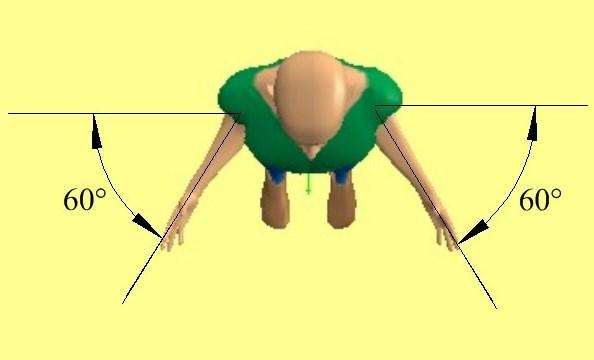


51 3D Static Strength Prediction Program Version Page 39 Figure 6.18: Horizontal angle measurements
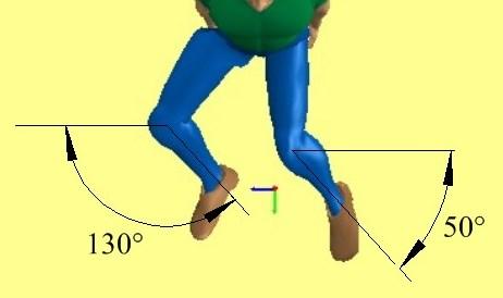
52 Page 40 3D Static Strength Prediction Program Version Vertical Angles Upper Arm Humeral Rotation Vertical angles are measured between the lower arm and the horizontal X-Y plane intersecting the superior joint of the link. This time instead of projecting the link line of the arm onto the plane we simply measure the angle between the link and the plane. When the body segment is level with the joint, the link is on the plane and the joint angle is 0 degrees. If the link is above the plane, then the vertical angle is positive; if below, then the angle is negative (Figure 6.19). This vertical angle measurement convention holds for the hand, lower arm, upper arm, clavicle, upper leg, lower leg, and foot. The measurement plane is the same as for the horizontal angle measurement in each case. Note that hand posturing is covered in Section 6.8. The shoulder joint is capable of three degrees of freedom. The upper arm horizontal and vertical angles define the direction of the upper arm but not the axial rotation about the upper arm bones (humeral rotation). 3DSSPP automatically determines the humeral rotation from the relationship between the lower and upper arms Upper Leg Femoral Rotation The hip joint, like the shoulder, is capable of three degrees of freedom. The upper leg horizontal and vertical angles define the direction of the upper leg but not the axial rotation about the upper leg bone (femoral rotation). 3DSSPP automatically determines the femoral rotation from the relationship between the lower and upper legs.


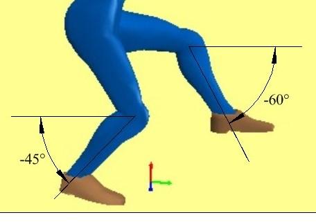

53 3D Static Strength Prediction Program Version Page 41 Figure 6.19: Vertical angle measurements


. 6.7.3.")

54 Page 42 3D Static Strength Prediction Program Version Clavicle Horizontal Angle The clavicle angles allow the shoulder joint itself to move with respect to the torso. Adjustment of the clavicle angles is only available in the 3D Dynamic Mode. The clavicle horizontal angle is the angle formed between the clavicle and the lateral dimension of the torso when viewing down the spine. Thus it is an angle local to the spine. If the clavicle is rotated forward of the torso, then the angle is positive; if the clavicle is rotated backward, then the angle is negative. This convention holds for both the right and left clavicle horizontal angles (Figure 6.20) Clavicle Vertical Angle The clavicle vertical angle is measured between the clavicle and the transverse plane intersecting the sternoclavicular joint. The transverse plane is perpendicular to the spine and so the angle is a local angle. When the clavicle is above the SCJ, the forearm vertical angle is positive; if below, the angle is negative (Figure 6.21). Figure 6.20: Clavicle horizontal angles Figure 6.21: Clavicle vertical angles
 onto the Z-Y plane and the positive Y axis (Figure 6.22). When standing straight, the trunk angle is 90 degrees.")


55 3D Static Strength Prediction Program Version Page Trunk Flexion Angle The trunk flexion angle is the angle between the projection of the trunk axis (the center of the hips to the center of the shoulders) onto the Z-Y plane and the positive Y axis (Figure 6.22). When standing straight, the trunk angle is 90 degrees. If the trunk is level with the horizontal plane (ground), the angle is 0. If the trunk is flexed below the horizontal plane, the angle is negative. The range of motion for this angle should be such that the angle between the trunk and the upper legs is between 40 and 100 degrees Trunk Lateral Bending Angle The trunk lateral bending angle is formed between the trunk axis and the Z-Y plane. If the torso is bent towards the positive X axis, the angle is positive. If the torso is bent toward the negative X axis, the angle is negative. Referring to Figures 6.23 a and b, note that this convention holds whether the torso is bent or erect. The range of motion for lateral bending is limited to +/-40 degrees. Note that within the biomechanical model the trunk is formed by the pelvis and the torso links which are each assigned separate angles based on the entered trunk flexion angle according to an algorithm derived from empirical data (Anderson, 1983). The two links are visible in the human graphics in the display view windows. (a) Figure 6.22: Trunk flexion angle (b) Figure 6.23: Lateral bending angle with stooped and non-stooped torsos

.")

56 Page 44 3D Static Strength Prediction Program Version Trunk Axial Rotation Angle The trunk axial rotation angle is defined as the rotation of the torso about the axis formed by the line segment from the L5/S1 disc to the center of the shoulders. The rotation should be measured as the left shoulder location relative to the X axis. If the left shoulder is rotated behind the X axis, the angle is positive (Figure 6.24a). If the left shoulder is rotated in front of the X axis, the angle is negative (Figure 6.24b). In other words, for counterclockwise rotation, the angle is positive and vice versa. The range of motion for this angle is limited to +/-90 degrees Pelvic Forward Rotation Angle Pelvic forward rotation is estimated by an algorithm within the 3DSSPP. However the angle can be altered in the Support Selection Dialog (Section 6.5). It is measured as the forward tilt of the pelvis about the centers of the hips (Figure 6.25). Draw a line from the center of the hips to the L5S1 and determine the angle between it and vertical. The axis of rotation is the Y axis. Forward rotation is positive for the purpose of the program Dialogs and reports. Internally, according to the right hand rule, it would be negative. The seated pelvis is normally tilted backward more than estimated by 3DSSPP so an adjustment is required. See the Support Selection Dialog (Section 6.5). The amount of adjustment varies widely as subjects tend to slump by varying amounts. (a) (b) Figure 6.24: Trunk positive axial rotation (a) and negative axial rotation (b) Figure 6.25: Forward tilt of the pelvis

. 6.7.3.")
57 3D Static Strength Prediction Program Version Page Pelvic Lateral Tilt Angle Pelvic lateral tilt is the rotation of the pelvis from side to side (Figure 6.26). The axis of rotation is the Y axis. Rotation to the right, towards the positive X axis, is positive and to the left is negative Head Flexion Angle The head flexion angle is a local angle measured with respect to the torso. As the torso is moved the head will stay in the same relative position. The angle is measure between the axis of the head/neck and a line drawn directly forward of the upper torso in a transverse plane at the C7T1 spine level (Figure 6.27) Pelvic Axial Rotation Pelvic axial rotation is the rotation of the pelvis about the Z axis. From overhead counterclockwise rotation is positive. Figure 6.26: Lateral tilt of the pelvis Figure 6.27: Head flexion angle

. Bending to the left is negative and to the right is positive.")


58 Page 46 3D Static Strength Prediction Program Version Head Lateral Bending Angle The head lateral bending angle is a local angle with respect to the torso. As the torso is moved the head will stay in the same relative position. The angle is measured between the axis of the head/ neck and the projection of the same axis on the sagittal plane of the torso (Figure 6.28). Bending to the left is negative and to the right is positive. The range of motion for head lateral bending is limited to +/-40 degrees Head Axial Rotation Angle The head axial rotation angle is a local angle measured with respect to the torso. As the torso is moved the head will stay in the same relative position. The rotation is about the axis of the head/neck (Figure 6.29). If the head is directed forward and symmetrical with respect to the torso, then the rotation angle is zero. Rotation to the right is negative and to the left is positive. (a) (a) (b) Figure 6.28: Head lateral bending angle (b) Figure 6.29: Head positive axial rotation (a) and negative axial rotation (b) with torso rotation

59 3D Static Strength Prediction Program Version Page HAND POSTURE Selecting Task-Input Hand Posture opens the Hand Posture Dialog (Figure 6.30). To manipulate the wrist simply enter the hand segment angles according to the definitions below. To enter a value in a specific field, click on the field or use the TAB key to move from field to field. After entering values select the Apply or OK buttons to affect the posture change. If the posture is symmetric, enter the angles for one side and click on the SYMMETRY button to copy the values to the other side of the body. A NEUTRAL button can be selected to reset the wrist angles to neutral such that the hand will be in line with the lower arm. A hand segment angles can also be altered using the INCREMENT buttons. Click on the angle value, then click on the increment value desired (1, 5, 10, 15, 20, 25), finally click on the "+" to increase the value in steps of the increment selected or click on the "-" to decrease the value. The posture will redraw automatically to provide feedback as to the effect of the incremental posture change. Note that when the Maintain Wrist Posture Angles is checked in the Body Segment Angles dialog if the lower arm is reoriented by changing the body segment angles or by other means, the relative hand orientation to the lower arm is kept constant. Thus the hand segment angles will be change as the lower arm is moved. The Set to forearm angles button will force the wrist to be straight and the hand will follow the angle of the forearm Hand Type The Hand Type box provides for the selection of various grasp types for the hominoid display. This does not currently affect biomechanical analyses. Only the open hand is available at this time Hand Segment Angles The hand angles allow manipulation of the wrist flexion and deviation and of the forearm rotation (supination/pronation). The hand segment is defined from the wrist center to the center of grasp. The angles are defined below. Figure 6.30: Hand Postures Dialog
.")

60 Page 48 3D Static Strength Prediction Program Version Hand Segment Horizontal Angle The horizontal angle is measured while looking down onto the arm (such that the hand segment is projected onto the X-Y plane at the wrist). The angle formed between the hand segment and the X axis constitutes the horizontal angle (Figure 6.31). When the hand segment is aligned with the X axis and the hands are pointing away from and to the side of the body, the angle is 0 degrees. When the the hand moves upward and decreases as the hand moves downward as indicated by Figure Be aware that, in this convention, the origin of the horizontal plane is located at the wrist and is independent of arm angles and overall body posture. Figure 6.31: Hand segment horizontal angles hand segment is pointing in front of the X-axis, the angle is positive. If the hand segment crosses behind the X-axis, then the angle is negative. This convention holds for both the right and left horizontal angles. Note that the horizontal angle does not have meaning when the hand segment is perfectly vertical (it has no projection onto the X-Y plane other than a point) and need not be entered in this case. Figure 6.32: Hand segment vertical angle Hand Rotation Angle The hand rotation angle is a measure of the axial rotation of the wrist about the bones of the forearm and may be known as wrist supination/ pronation. The angle is a local angle measured with respect to the arm posture and its magnitude is difficult to estimate from observation. Therefore it is best to enter a value and adjust it until the hominoid appears correct. Technically the magnitude is the angle difference between the axis of the elbow and the flexion/extension axis of the wrist (Figure 6.33) Hand Segment Vertical Angle The vertical angle is formed between the hand segment and the horizontal X-Y plane intersecting the wrist. When the hand is level with the wrist, the joint angle is 0 degrees. If the hand is above the wrist, the vertical angle is positive; if below, the angle is negative. For both the right and left hand vertical angles, the value of the angle increases as


61 3D Static Strength Prediction Program Version Page POSTURE PREDICTION Introduction to the Inverse Kinematics Method of Posture Prediction Figure 6.33: Hand rotation angle Note that if the elbow included angle is 180, the elbow is straight, then the Hand Rotation Angle also affects the rotation of the upper arm, the humeral rotation angle. When the elbow is bent this angle is given by the orientation of the forearm with respect to the upper arm. When the elbow is not bent, the humeral rotation is unknown. In this case one half of the hand rotation angle is applied to the upper arm and one half to the lower arm. 6.9 PRE-SET POSTURES Selecting Task-Input Pre-Set Posture displays a list of postures (Figure 6.34) that can be selected and applied to the hominoid. These can be used as a starting point when entering postures via the body segment angles or other methods. Choosing Task-Input Posture Prediction indicates the inverse kinematics method of posture entry is to be used. The concept of inverse kinematics is that if the positions of the hands relative to the feet can be specified, the positions of the other body joints and segments can be computed from algorithms based upon behavioral data. This means that in order to specify a posture, all that needs to be done is for the analyst to enter the positions of the hands, and the program will automatically predict the locations of the other body segments and joints. This prediction is based on these hand locations, the anthropometry of the worker, and the load at the hands. However, because the inverse kinematics algorithm is based upon regression equations, it yields the average posture a person would tend to take as a function of the hand locations and other task parameters. Obviously, because of behavioral, experiential, and training differences between individuals, not everyone will assume the same posture when the hands are at the same location. However, predicting a posture from known hand locations is always a good starting point for an analysis, since the preferred posture generated by inverse kinematics Figure 6.34: Pre-Set Posture Dialog

62 Page 50 3D Static Strength Prediction Program Version algorithm is typically a reasonable posture for the sake of analysis. Once the starting posture is specified, the posture can be fine-tuned through manipulating or moving individual body joints or segments. Thus, in most cases, the general procedure employed when using the inverse kinematics method will be to first specify a starting posture by setting the locations of the hands, and then adjusting the posture by manipulating other joints of the body. No matter how much the rest of the body is manipulated, the hands will remain in the same position Posture Prediction Dialog The Posture Prediction Dialog (Figure 6.35) is used to specify the positions of the hands relative to a point on the floor between the ankles. Note that the hand orientation helps the computer decide upon elbow elevation. When the palm is prone (palm down), the elbow tends to be higher in the air. The elbow is lower when the hand is semi -prone and is very low when the palm is supine (palm upward). A good rule of thumb is that if there is any doubt about the hand orientation, choose neutral. If the palm is not completely pointing down or completely pointing up, the best choice is neutral. To use posture prediction enter the hand locations referenced to the Measurement Coordinate Center. The Tab key can be used to move to each entry box. Horizontal: refers to the distance from the reference point in the forward-backward direction where forward distances are positive and backward distances are negative. Vertical: refers to the vertical distance from the reference point where positive values are above the point and negative values are below the point. Lateral: refers to the side-to-side distance from the center point where positive values are to the right and negative values are to the left of the subject. If the posture is symmetric, enter the angles for the right hand and click on the SYMMETRY button to copy the values to the left side LOCKING MODE One way to enhance the direct manipulation posture entry method is by using segment locking. This feature allows certain body segments of the modeled posture to be locked, preventing the inverse kine- Figure 6.35: Posture Prediction Dialog


63 3D Static Strength Prediction Program Version Page 51 locked, the legs will be re-predicted and the joint angles changed by the inverse kinematics algorithm. Other segments and combinations can be locked. The locked joint markers change to hollow circles which cannot be selected for direct manipulation. The Locking Mode Dialog is shown in Figure HAND LOADS Figure 6.36: Locking Mode Dialog matics algorithm from changing the joint angles of those segments. For example, if the legs are in the desired posture, the legs should be locked before manipulating the hand positions. If the legs are not The Hand Loads Dialog is used to enter loads at the hands (Figure 6.37). Please note that, in 3DSSPP, hand load refers to the load being applied TO the hand, not the load applied by the hand. A verbal description of the action of each hand in response to the load exerted on it is displayed to confirm the correct entry. Separate force magnitudes and directions are entered for each hand. The force directions may be entered using direct manipulation (Section 3.3.1). Figure 6.37: Hand Loads Dialog
64 Page 52 3D Static Strength Prediction Program Version The magnitude and angle values can be altered using the INCREMENT buttons. Click on the value to change, then click on the increment value desired (1, 5, 10, 15, 20, 25), and finally click on the "+" to increase the value in steps of the increment selected or click on the "-" to decrease the value. The biomechanical output values will update immediately. In 3D Dynamic Mode loads will be applied to all selected frames. See Chapter Horizontal Hand Force Angle Illustrating the hand load force as a vector with its tail in the grip center of the hand and its arrow pointing in the direction of the force, the hand load horizontal angle is the angle between the X axis and the force vector when viewing the figure from overhead (i.e. when the force vector is projected onto the X-Y plane). If the vector is directed forward of a vertical plane at the hand, the angle has a range of 0 to 180 degrees. If the vector is directed behind a vertical plane at the hand, the angle has a range of 0 to -180 degrees. For both hand vectors, 0 lies along the positive X axis. Refer to Figures 6.38 and 6.39 for clarification. Figure 6.39: Negative hand force vector horizontal angles Note that the horizontal angle does not have meaning when the force direction is perfectly vertical (it has no projection on to the X-Y plane other than a point) and need not be entered in this case Vertical Hand Force Angle Assuming the hand force vector tail is in the grip center of the hand, the angle between the vector and the horizontal X-Y plane is the hand force vertical angle. If the vector is directed above the horizontal plane, the angle has a range of 0 to 90 degrees. Should the vector be directed below the horizontal plane, the angle ranges from 0 to -90 degrees. Refer to Figure 6.40 for additional clarification. Figure 6.38: Positive horizontal hand force vector angles

65 3D Static Strength Prediction Program Version Page Zero All This button will clear all the entered hand load forces and torques EXTERNAL APPLIED FORCES AND MOMENTS Figure 6.40: Vertical hand force vector angles with right horizontal angle of 0 and left horizontal angle of ADVANCED HAND LOADS In addition to the Hand Loads Dialog, 3DSSPP provides the Advanced Hand Loads Dialog (Figure 6.41) for component entry of hand loads. To enter either a force or a torque for either hand, just enter the component forces or component torques, and SSPP will automatically compute the total torque or force. The coordinate system is defined with the X- axis extending laterally with positive to the subjects right. The positive Y-axis extends forward and the positive Z-axis extends vertically. This forms a right-had coordinate system and the forces and moments are defined accordingly. In 3D Dynamic Mode loads will be applied to all selected frames. See Chapter 10. The External Applied forces and Moments Dialog box is used to enter loads at joints other than the hands (Figure 6.42). Torques and forces can be applied to any listed joint (Elbows, Shoulders, L5S1, Hips, Knees, Ankles). Use this functionality to simulate situations like leaning against a table (force on the hips) or carrying a backpack (force and torque on the shoulder). By default joint forces are displayed in the Orthogonal-View Windows. To turn off the display of these joints, uncheck the 3-Views Show Forces Menu option. In 3D Dynamic Mode loads will be applied to all selected frames. See Chapter Zero Current This button will zero the entered force and torque for the currently selected joint. Figure 6.41: Advanced Hand Loads Dialog

66 Page 54 3D Static Strength Prediction Program Version Batch File Format First Line of File The first line of all batch files must be: 3DSSPPBATCHFILE # Command Structure Figure 6.42: External Applied Forces and Moments Dialog Zero All This button will clear the entered forces and torques on every joint even those not currently shown. This button will not affect hand loads. All lines must have one and only one command. The command must begin with a command name, upper case only, and must end with the terminating character #. No characters should follow the terminating character. Blanks are used to delimit all commands, data items, and the terminating character. At least one blank must be used; additional blanks for visual organization are acceptable. The legal commands and their abbreviations are as follows: 6.15 RUN BATCH FILE The Run Batch File feature enables automatic analysis of tasks specified in a data file. It is useful when many biomechanical analyses are to be performed on data derived from another program. The input data file must follow a specific format and must include all of the information normally specified for an analysis. The results of the analyses are output to an export file (Section 11.17). A log file is also produced. Both file locations default to the folder containing the batch file. ANTHROPOMETRY AUTOEXPORT COMMENT DESCRIPTION EXPORT FRAME HANDLOADS SEGMENTANGLES SEGMENTANGLES V5 POSTUREPREDICTION PAUSE (ANT) (AUT) (COM) (DES) (EXP) (FRM) (HAN) (JOA) (JOI) (PPR) (PAU)
67 3D Static Strength Prediction Program Version Page ANTHROPOMETRY Command The ANTHROPOMETRY command is used to set the gender and anthropometry values for the subsequent analyses. The first data item is an integer representing the gender; Male is 0 and Female is 1. The second data item is an integer representing the percentile for height and weight; 95 th is 0, 50 th is 1, and 5 th is 2. If the percentile integer is 3 then the height and weight are set according the next two data items. The third data item is the entry for Height and the last data item is the entry for Weight. These are both floating point values. If the percentile data item is not 3 then the third and last data items are not used in the analysis and should be entered as zeros DESCRIPTION Command The DESCRIPTION command is used to set the analysis units and the three documentation fields which are normally entered under the Task Description Dialog. The first data item is an integer, either 0 or 1, which sets the analysis units. English is 0 and metric is 1. The remaining four data items are strings which must be enclosed in quotes. They are the Task Name, Analyst Name, Analysis Comment, and Company Name. A typical description command line is as follows: DES 0 "Task Name" "Analyst Name" "Just some comments." "Company" # ANT # EXPORT Command AUTOEXPORT Command The AUTOEXPORT command causes all subsequent ANT, HAN, JOA, JOI, and PPR commands to be followed by an analysis and exportation of result to the export file. The data item is an integer digit representing the desired state of the command. On is 1 and off is 0. The EXPORT command initiates an analysis and exports the results to the export file. The data exported and the format are controlled by the Export Output Summary Report command (Section 11.16). The exported filename will be the batch filename with the extension.exp. This command has no data items. EXP # AUT 1 # COMMENT Command The COMMENT command is used to document the batch file and can be used as often as desired in the batch file. It is ignored by 3DSSPP. An ordinary comment command might be entered as follows: COM Anything you want to type to document your file. #
68 Page 56 3D Static Strength Prediction Program Version FRAME Command PAUSE Command The FRAME command specifies the program s current frame. Subsequent batch commands will operate on this frame. If the frame command is not used in a batch file then all commands will apply to the current frame before starting the batch file. Parameters for the FRAME command include: + n move n frames forward The PAUSE command causes a pause after all subsequent analyses. The data item is an integer representing the desired length of the pause in milliseconds. If the integer given is 0, then a message window is displayed instructing the user to click to continue. PAU 0 # - n move n frames backward n move to frame n FIRST move to first frame LAST move to last frame There must be spaces between the command and the parameter. There must also be a space between the operator (+ or -) and the frame number (n). FRM LAST # FRM + 1 FRM POSTURE PREDICTION Command The POSTUREPREDICTION command performs a posture prediction using the hand locations as in the programs posture prediction command. The values to be entered and their order are: : Left hand horizontal location, left hand vertical location, left hand lateral location, right hand horizontal location, right hand vertical location, right hand lateral location, and Hand Orientation. The units can be either inches or cm and will be interpreted depending upon the units mode of the program when the batch file is run. The Hand Orientation value must be either 0,1, or 2 corresponding to pronated, neutral, and supinated. PPR # HANDLOADS Command The HANDLOADS command is used to input the magnitude and direction of the loads on each hand for the subsequent analyses. The magnitude data items are floating point values and the angle data items are integers. The values must be specified in the following order: Left magnitude, left vertical angle, left horizontal angle, right magnitude, right vertical angle, and right horizontal angle. HAN #
69 3D Static Strength Prediction Program Version Page SEGMENTANGLES Command The SEGMENTANGLES command is used to enter the posture segment angles as listed in the Segment Angles Menu Dialog for subsequent analyses. (See the next command for compatibility with Version 5 batch files.) All of the values are integers and the data items are input in the order of left side, right side, and trunk. Specifically: Hand left horizontal, hand left vertical, hand left rotation, forearm left horizontal, forearm left vertical, upper arm left horizontal, upper arm left vertical, clavicle left horizontal, clavicle left vertical, upper leg left horizontal, upper leg left vertical, lower leg left horizontal, lower leg left vertical, foot left horizontal, foot left vertical, hand right horizontal, hand right vertical, hand right rotation, forearm right horizontal, forearm right vertical, upper arm right horizontal, upper arm right vertical, clavicle right horizontal, clavicle right vertical, upper leg right horizontal, upper leg right vertical, lower leg right horizontal, lower leg right vertical, foot right horizontal, foot right vertical, head flexion, head rotation, head lateral bending, neck flexion, neck rotation, neck lateral bending, trunk flexion, trunk rotation, trunk lateral bending, pelvis rotation, and pelvis lateral bending SEGMENTANGLES Command for Version 5 Angle Definitions 3DSSPP Version 5 used different body segment angle definition for the legs. This command is has been retained to support older batch files. New batch files should use the JO6 command to specify the posture. All of the values are integers and the data items are input in the order of left side, right side, and trunk. Specifically: Forearm left horizontal, forearm left V, upper arm left horizontal, upper arm left vertical, upper leg left vertical, lower leg left vertical, forearm right horizontal, forearm right vertical, upper arm right horizontal, upper arm right vertical, upper leg right vertical, lower leg right vertical, trunk flexion, trunk rotation, and trunk bending. JOI # JOA #
70 Page 58 3D Static Strength Prediction Program Version Example Batch File 3DSSPPBATCHFILE # COM # DES 0 "Sample Batch" "Suzy Anybody" "Nothing very meaningful" "Company" # AUT 0 # PAU 0 # ANT # JOA # HAN # EXP # COM # COM # COM Enable auto export and do 5 different hand loads # AUT 1 # DES 0 "Loads A" "Suzy Anybody" "Hand loads case A" "Company" # HAN # DES 0 "Loads B" "Suzy Anybody" "Hand loads case B" "Company" # HAN # DES 0 "Loads C" "Suzy Anybody" "Hand loads case C" "Company" # HAN # DES 0 "Loads D" "Suzy Anybody" "Hand loads case D" "Company" # HAN # DES 0 "Loads E" "Suzy Anybody" "Hand loads case E" "Company" # HAN # COM # COM # COM Do the 3 different percentiles for female with English output # COM Note: For values of percentile not equal to 3, the height and weight # COM data entries are ignored and may be anything readable (here set to 0) # COM # DES 0 "Anthro A" "Suzy Anybody" "Female 5th" "Company" # ANT # DES 0 "Anthro B" "Suzy Anybody" "Female 50th" "Company" # ANT # DES 0 "Anthro C" "Suzy Anybody" "Female 95th" "Company" # ANT # 6.16 OPERATION OF 3DSSPP FROM WITHIN ANOTHER PROGRAM Version 6 can be configured such that the 3DSSPP calculations can be used within another program. The model calculations are contained in a dll and it requires a special licensed from the University of Michigan.

71 3D Static Strength Prediction Program Version Page 59 Chapter 7: DISPLAY MENU COMMANDS The Display Menu (Figure 7.1) contains the Dialog boxes for controlling the program display window. Automatic tiling of the default five window arrangement can be enabled or disabled, or the program can be tiled on command. In addition the Message Bar can be displayed or hidden. 7.2 TILE NOW If the Tile Now command is selected the view window tiling will be reset to the standard 3 over 2 arrangement. 7.1 AUTO TILE If the Auto Tile command is checked, then the standard 3 over 2 arrangement of the view windows will be reset when ever the program window is sized. If an alternative arrangement of the view windows is desired, then the Auto Tile feature should be disabled. To enable or disable simply click on the command. 7.3 STATUS BAR This command controls the appearance of the Message Bar. The Message Bar displays various help and error messages. It is displayed if the command is checked and hidden if it is not checked. To check or uncheck simply click on the command.
. Custom upper and lower limits for males and female can easily be entered.")

72 Page 60 3D Static Strength Prediction Program Version STRENGTH LIMITS The strength limits shown on the screens and used in the reports are set in the Strength Limits Dialog (Figure 7.2). The default values are from NIOSH, (Section ). Custom upper and lower limits for males and female can easily be entered. The center of the measurement coordinate system can be set using the Measurement Coordinate System Origin Dialog (Figure 7.3). Changing the center will alter all of the entered, displayed, and reported location values. The default center for standing mode cases is at the center of the feet. (Center of the ankles projected downward to the floor support of the lowest foot.) For seated mode cases the default center is at the Seat Reference Point (SRP). Center locations other than the default can be set using the Dialog. 7.5 MEASUREMENT COORDINATE SYSTEM ORIGIN Figure 7.2: Strength Limits Dialog Figure 7.3: Measurement Coordinate System Origin Dialog
 can be used to hide or display the main program windows.")
73 3D Static Strength Prediction Program Version Page WINDOW DISPLAY SELECT The Window command (Figure 7.4) can be used to hide or display the main program windows. If a window is accidently closed by selecting a title bar box, then it can be re-displayed using this command. Figure 7.4: Windows Display Select
74 Page 62 3D Static Strength Prediction Program Version 6.0.6
 contains the Dialog boxes for controlling the display attributes of the three Orthogonal-View Windows. These windows may be rearranged and manipulated as desired by the analyst.")

75 3D Static Strength Prediction Program Version Page 63 Chapter 8: ORTHOGONAL-VIEW (3-VIEWS) MENU COMMANDS The 3-Views Menu (Figure 8.1) contains the Dialog boxes for controlling the display attributes of the three Orthogonal-View Windows. These windows may be rearranged and manipulated as desired by the analyst. The Orthogonal-View Windows consist of three views: top view (horizontal plane), front view (frontal plane), and right side view (sagittal plane). When a new task file is opened, the default layout locates the top view in the top left window, the front view in the top center window, and the side view in the top right window. The figures, representing the posture being modeled, are drawn to scale according to the selected anthropometry and include force direction arrows when applicable (force vectors which are perpendicular to the plane of the screen are not drawn). These are the only windows in which direct manipulation can be used to adjust the modeled posture; in addition, direct manipulation can only be used when the figures are displayed as stick figures. 8.1 SHOW FORCES Selecting 3-Views Show Forces allows the user to toggle the display of joint and hand forces in the Orthogonal-View Windows. 8.2 COLORS Selecting 3-Views Colors brings up a Dialog box (Figure 8.2) that allows the user to change the color of elements in the Orthogonal-View Windows. To change any color, simply click the corresponding button and use the Color Selection Dialog box to choose a new color. Figure 8.1: 3-Views Menu Figure 8.2: 3-Views Colors Dialog
76 Page 64 3D Static Strength Prediction Program Version 6.0.6
 contains the Dialog boxes for controlling the display attributes of the Oblique-View Window.")
77 3D Static Strength Prediction Program Version Page 65 Chapter 9: OBLIQUE-VIEW MENU COMMANDS The Oblique-View Menu (Figure 9.1) contains the Dialog boxes for controlling the display attributes of the Oblique-View Window. While the orthogonal-views are useful for viewing vertical and horizontal angles for data entry, they do not offer an accurate means of comparing the final posture to photographs or video of the actual worker performing the task. 3DSSPP provides this user-defined oblique-view utilizing a Graphic Human Model. This view simplifies the process of comparing the modeled posture to photographs and aids in accurately representing the actual task. In the Oblique-View Window the human figure may be viewed from any distance and view angle. Additionally, a camera focal length can be simulated which changes the perspective in the scene. This is very useful when comparing the modeled posture to photographs taken with different focal length lenses since different focal lengths produce different perspective distortions. These can be matched by setting the focal length to match the camera using the Oblique-View Camera command. The Oblique-View Window can also enhance posture evaluation and realism if environment objects are used. 3DSSPP provides three different kinds of objects that can be placed in the figure s immediate environment: a hand-held object (cube, sphere, or cylinder), a barrier (vertical wall or horizontal table), and a floor. The barrier can be userdefined for length and width as well as positioned using a cylindrical coordinate system centered on the human figure. 3DSSPP automatically fits the handheld object to the space between the figure s hands and always centers the hands on the sides of the hand-held object. If the task being modeled involves an asymmetrically held object, the oblique -view image will not match the actual task. This is a function of the graphics display and has no bearing on the biomechanical analyses. 9.1 HUMAN FIGURE Figure 9.1: Oblique-View Menu
 which allows the user to select the following display options relevant to the human figure. This selection applies shoes to the oblique display of the human model.")
78 Page 66 3D Static Strength Prediction Program Version Selecting Oblique-View Human Figure displays a dialog box (Figure 9.2) which allows the user to select the following display options relevant to the human figure. This selection applies shoes to the oblique display of the human model. It makes no difference to the calculations or results Model Type Two graphic models of the human figure are provided. The default is to display the Flesh figure model. The Wireframe figure model is transparent and shows the surface elements (quadrangles) used in both figure models Clothing Color These buttons allow the user to change the color of the hominoid s apparel. Individual colors can be specified for shirts and pants for both males and females Skin Color Enable Shoes Figure 9.2: Oblique-View Hu-

79 3D Static Strength Prediction Program Version Page 67 The figure s skin can be changed to any color. The current skin color is displayed in the color box. To change the color, click Skin Color button and select a new color using the provided dialog box Floor This object (Figure 9.4) has fixed dimensions and is automatically positioned beneath the figure s feet. Click on the box to insert or remove the floor from display. 9.2 ENVIRONMENT Selecting Oblique-View Environment displays a dialog box (Figure 9.3) which allows the user to select the following display options relevant to environment objects. This feature is provided to aid the analyst in matching postures to photographs or video images. However, physical interaction between the environment items and the human figure is not calculated nor are analysis results affected by the presence or absence of environment objects Handheld Object Be aware that 3DSSPP always positions the handheld object between the hands with the hands centered on the sides of the object: if the task being modeled involves an asymmetrically held object, the modeled image will not match the actual task. The inclusion of the hand-held object on the graphics display has no bearing on the biomechanical analyses and is only included for realistic appearance. Type: Four object options are available - none, cube, cylinder, or sphere. The object is automatically positioned at the midpoint of the hands and scaled to fill the space between the hands. The default is no object. Height: With this field, the vertical dimension of the handheld object is specified in inches or centimeters, depending on the units currently selected. The vertical dimension is measured from the bottom to top of the object at its largest cross section. Depth: With this field, the horizontal (forward-backward) dimension of the handheld object can be specified in inches or centimeters, depending on the units currently selected. The horizontal dimension is measured from the front of the object (farthest side from the figure) to its back (closest side to the figure) along a line that lies in the global horizontal plane and is perpendicular to the line connecting the hand centers. In the three-dimensional display, typically appears as the depth of the object when the figure is viewed from the side. Figure 9.3: Oblique-View Environment Dialog

80 Page 68 3D Static Strength Prediction Program Version Figure 9.4: Example of Oblique-View environment Barrier A barrier represents either a wall or a table as a thin plate of user-defined thickness. A wall and a table cannot be displayed simultaneously. The barrier may be repositioned if it appears to be in contact with the humanoid. The Distance, Elevation, and Azimuth input fields refer to a cylindrical coordinate system with the origin at the center of the feet at the height of the lowest foot. The central axis points up vertically and the angle reference line projects straight ahead from the figure. Type: Three barrier options are available - none, wall, and table. Only one barrier can be displayed at a time and the default is no barrier. The wall type is oriented vertically and always faces the figure. The table type is oriented horizontally with its inner edge always facing the figure. Length: This field specifies the barrier s left-toright horizontal dimension. This dimension appears the same and is measured the same for either the wall or the table barrier types. Width: This field allow the user to specify the barrier s vertical dimension as a wall or its horizontal front-to-back dimension as a table. Thickness: This field allows the user to specify thickness of the barrier. Distance: This input field specifies the radial distance of the barrier from the hominoid s central vertical axis. For both the wall and the table, this dimension is measured horizontally from the vertical axis of the cylindrical coordinate system to the barrier s center (see above). Azimuth: This input field specifies, in degrees, the angular position of the barrier s center with respect to a reference line projecting straight out in front of the hominoid from the feet center point. Facing the hominoid from the front, positive azimuth values move the barrier to the viewer s right (the figure s left) in a circular arc centered on the cylindrical coordinate system s vertical axis. Negative azimuth values move the barrier around to the viewer s left. The range of azimuth values is -180 to 180 degrees. Elevation: For both the wall and the table, this input field asks for the dimension measured vertically from the origin to the barrier s top surface Color Environment items can be displayed in any color including a separate color for the outline.
; circling around the figure to the right or left (changing rotation); or circling up and over or down and under")
81 3D Static Strength Prediction Program Version Page CAMERA For viewing the figure, the human graphic display uses a camera metaphor. Viewing position is changed by moving toward or away from the figure (changing radius); circling around the figure to the right or left (changing rotation); or circling up and over or down and under the figure (change in vertical tilt). As this movement occurs, the camera remains directed on the figure s hips and always upright (e.g., does not roll). In addition, the figure can be made to appear larger or smaller by increasing or decreasing the camera s focal length, similar to using a zoom lens. 3DSSPP provides the camera metaphor for more exact matching of hominoid postures to photographs or video. Selecting Oblique-View Camera displays a dialog box (Figure 9.5) which allows the user to select the following model viewing options. Focal Length: This field specifies the camera s focal length. High focal length values magnify and flatten the image, low values make the image smaller and distorted. Distance: This field specifies the radial distance of the camera s film plane to the center of the figure s hips. Vertical Tilt This field specifies the vertical angle of the camera in degrees. Vertical tilt is a measure of the angle from the horizontal plane at which the object is being observed. Ranging from - 89 to 89, 0 is at waist level looking at the object and 89 is directly overhead looking down on the object. Rotation: This field specifies the angle from a vertical plane separating the left and right halves of the object from which it is being observed. Ranging from -180 to 180 degrees, 0 degrees is looking directly at the front of the figure while 90 degrees is looking at the figure s left side (observer s right side). The camera view can be adjusted using the mouse by clicking and dragging in the Oblique- View Window (Section 3.3). 9.4 BACKGROUND Selecting Oblique-View Background allows the user to set the background of the Oblique-View Window for the task being analyzed to either a solid color or a digital image (Figure 9.6) Image Click on Browse to load a digital image file and set it as the background for the oblique window. The Windows file input dialog will appear. Select an image file and click Open. Currently supported file types include: gif, ico, and jpeg. Be sure the Use Image box is checked and select Apply. The digital image will appear in the background of the oblique window. The Graphic Human Model will be visible on top of the image. Choose either Center or Stretch to adjust the view of the image. Figure 9.5: Oblique-View Camera Dialog


82 Page 70 3D Static Strength Prediction Program Version Figure 9.6: Oblique-View Background Dialog Color If a background image is not selected then the background is set as a solid color. The solid color can be changed by clicking on Select Color. The Windows colors dialog will appear and a new color can be selected or created. lighting is another option to control the positioning of a single light source illuminating the hominoid Figure Transparency The transparency of the figure can be controlled to all the digital photo image to appear through the figure. Adjust the slider to achieve the desired effect. 9.5 LIGHTING The Lighting Dialog (Figure 9.7) controls the shading of the hominoid. Automatic shading can be selected by checking the Use fixed 3-point lighting scheme button. The light intensity can then be chosen for the desired effect. The Single-Point Figure 9.7: Oblique-View Lighting Dialog

83 3D Static Strength Prediction Program Version Page 71 Chapter 10: ANIMATION MENU COMMANDS The Animation Menu (Figure 10.1) contains commands to enter a series of frames into 3DSSPP. The frames are assumed to be a sequence of postures forming an animation of a motion, but they could just be a collection of static postures. The menu is only available in 3D Dynamic mode (Section 6.3). Table 10.1 Local Per-Frame Parameters Body segment angles Hand posture angles Hand type Hand forces, (x, y, z) Hand torques, (x, y, z) External applied forces and moments 10.1 FRAME PARAMETERS FOR BIO- MECHANICAL ANALYSES Most 3DSSPP parameters are global and apply to all frames. Others are local and can be specified for each frame individually. The local parameters are listed in Table The local parameters are posture angles and loads on the body. This means that the forces on the body can be changed during a simulated motion. Nothing else besides posture and loads can be changed from frame to frame ANIMATION FRAME CONTROL BAR In 3D Dynamic mode the animation frames are depicted on the Animation Frame Control Bar at the bottom of the program window (Figure 10.2) and appear as a frame timeline. The frame number is below the timeline and the time in seconds is above. Frames may or may not be defined with entered data. Upon default startup only frame one will contain data. Each numbered animation frame generates a biomechanical analysis specific to the posture and other information contained in the frame. To display and analyze a frame simply select it by Figure 10.1: Animation Menu

84 Page 72 3D Static Strength Prediction Program Version Figure 10.2: Animation Frame Control Bar clicking with the mouse. The right and left cursor arrow keys can be used to scroll through the frames as well. Use the SHIFT key to select multiple frames. The loads can be changed for a selection of frames. The frames shown on the Frame Control Bar are color coded. Green frames are key frames entered by the user. Pink frames are predicted using interpolation. Orange frames are predicted using the Reach Motion Prediction algorithm. Undefined frames are blank. Figure 10.3: Animation Context Menu Playing Animation Frames The defined, or entered, frames can be viewed like an animation by using the player on the left side of the Animation Frame Control Bar. The player controls include Go to Start, Step Backward, Play Backward, Pause, Play Forward, Step Forward, and Go to Last. They behave as expected Animation Edit Buttons Two buttons are available at the right end of the bar to help add and delete frame from the timeline. These are in addition to the editing commands available in the context menu (Section ) Animation Context Menu The Animation Frame Control Bar context menu will appear when the bar is right clicked (Figure 10.3). This menu allow the editing of the frame time-line including. Other animation related commands are also available as buttons (Section ) or in the Animation Menu Inserting a String of Blank Frames A special command is available to insert a series of frames into the timeline. Place the mouse cursor between two frames and click on the downward arrow the appears. The box shown in Figure 10.4 will allow frames to be inserted at the point of the arrow. Clicking on the arrow and dragging it to the right will automatically insert frames and do a linear interpolation between the original two frames.

85 3D Static Strength Prediction Program Version Page 73 Figure 10.4: Animation frame insert function L. Metatarsalphalangeal Skin Surface R. Hip Joint Center R. Knee Joint Center R. Lat. Epicon. of Femur Skin Surface R. Ankle Joint Center R. Lateral Malleolus Skin Surface R. Ball of Foot Virtual point R. Metatarsalphalangeal Skin Surface (Bold named values are required for 3DSSPP.) 10.3 IMPORT LOCATION FILE The Animation Import LOC File command allows the entry of a special file of frames of body joint center locations (X,Y,Z). The format must be as follows: Value Anatomical Location Attribute 1-3 Top Head Skin Surface 4-6 L. Head Skin Surface 7-9 R. Head Skin Surface Head origin Virtual point Nasion Skin Surface Sight end Virtual point C7/T1 Joint Center Sternoclavicular Joint Joint Center Suprasternale Skin Surface L5/S1 Joint Center PSIS Joint Center L. Shoulder Joint Center L. Acromion Skin Surface L. Elbow Joint Center L. Lat. Epicon. of Humer. Skin Surface L. Wrist Joint Center L. Grip Center Virtual point L. Hand Skin Surface R. Shoulder Joint Center R. Acromion Skin Surface R. Elbow Joint Center R. Lat. Epicon. of Humer. Skin Surface R. Wrist Joint Center R. Grip Center Virtual point R. Hand Skin Surface L. Hip Joint Center L. Knee Joint Center L. Lat. Epicon. of Femur Skin Surface L. Ankle Joint Center L. Lateral Malleolus Skin Surface L. Ball of Foot Virtual point 10.4 PREDICT REACH MOTION The Animation Predict Reach Motion command can be used to predict and enter a reach type motion as a sequence of frames. The prediction is based upon data collected and analyzed at the U of Michigan Center for Ergonomics under the Human Motion Simulation ( research project (Faraway, et al., 2000 and 2003). A functional regression approach was taken to analyze approximately 17,000 reaching and transfer tasks demonstrated by male and females of varying stature and age. The model is known as HUMOSIM M1 and was the first attempt to model the collected motion database. The motions in the database were seated and standing pointing reach motions and seated and standing transfer motions with one or two hands. The motions included both reach and return from target locations spread around the reach envelop. For the transfers the motions were divided into four phases: reach to place the object, return to home without object, reach to get object, and return to home with object. The home location was a natural hand location in front of the subjects waist. For seated driving cases it was a natural steering wheel hand location posture. In addition to the HUMOSIM MI model the prediction dialog allows a motion to be predicted using linear interpolation between the body segment angles of two entered postures. The two entered postures could also be predicted using the static posture prediction capability of 3DSSPP.


86 Page 74 3D Static Strength Prediction Program Version Dialog for HUMOSIM Motion Prediction Standing or Seated Mode The Predict Reach Motion Dialog using the HUMOSIM model is shown in Figure The three graphic displays at the top of the dialog display the starting posture, the created motion, and the ending posture. These displays can be set to display either the oblique figure or one of the 3- View figures (Figure 10.6). The starting and ending postures can be predicted or specified from previously created frames. Using the middle display the user can play and adjust the motion being created before inserting the motion frames into the frame timeline. Below the three display windows are the parameters required for the motion prediction. Figure 10.6: Figure graphic choices Figure 10.5: Predict Reach Motion standing dialog
87 3D Static Strength Prediction Program Version Page 75 When the OK button is selected the frames of the predicted motion will be inserted into the frame timeline after the currently selected frame Reach Type The reach type is either two handed, one handed neutral, or one handed prone. Two handed is as holding a two handled tote box. One handed neutral would be like holding an open jar of pickles or a vertical pole. One handed prone would be like lifting a lunch pail by the handle in front of you with your palm down or like lifting a horizontal pole Offset Between Hands The offset between hands is the distance between the hands when predicting a two handed transfer. The X offset must be positive. The Y and Z values can be positive or negative and direct the location of the right hand with respect to the left Box Angle When using two hands, this parameter can be used to simulate the rotation of the box with respect to the human figure. The rotation in degrees can be either positive or negative Initial and Final Postures The initial and final motion postures can be set by specifying a target hand location or by using previously defined frames. The previously defined frames must be the currently selected frame and the immediately following frame Motion Length The motion length sets the time duration of the motion and can be specified in seconds or by the number of frames. 3DSSPP uses 25 frames per second Dialog for Interpolation Motion Prediction Standing or Seated Mode The Predict Reach Motion Dialog for linear interpolation is shown in Figure The three oblique windows at the top of the dialog display are the same as for the HUMOSIM model dialog and serve the same purpose. The interpolation parameters are below the display windows Initial and Final Postures The initial and final motion postures are set using previously defined frames. The previously defined frames must be the currently selected frame and the immediately following frame. If the immediately following frame is not defined then the created motion is simply a duplication of the starting frame Motion Length The motion length sets the time duration of the motion and can be specified in seconds or by the number of frames. 3DSSPP uses 25 frames per second.

88 Page 76 3D Static Strength Prediction Program Version Figure 10.6: Predict Reach Motion using interpolation 10.5 EXPORT AVI FILE This command will create an avi video file of the frames in the Animation Bar. A filename dialog will allow the entry of a filename and location. Note that the frame rate is 25 per second and that avi viewers may not play the avi at that rate.

89 3D Static Strength Prediction Program Version Page 77 Chapter 11: REPORTS MENU COMMANDS The Reports Menu (Figure 11.1) contains the many analysis options available in 3DSSPP. A task input summary report is also available which lists all of the input data entered by the user. Two additional options include commands for printing reports and exporting output data to a file. When a report is selected, the report data is displayed in a new window over the posture entry windows which may be manipulated as any other window. For example, its contents can be printed through File Print Active Window or be copied to the clipboard, or the window can be re-sized. Changes in units, anthropometry, load, or posture will automatically be reflected in any open report windows. Remember that, although running additional reports may appear to close an existing report window by hiding the previous report window, no existing report windows are closed by this action. To close individual report windows, use the control menu on the report window s title bar. Each report contains a header block with basic Figure 11.1: Reports Menu

90 Page 78 3D Static Strength Prediction Program Version information about the analyzed task. Included are the company, analyst, date, task name, gender, percentile anthropometry, height, weight, and task comment. For all report screens the output can be toggled between English or Metric units by choosing Task-Input Metric or Task-Input / English (Section 6.2). The windows do not have to be closed to change the units. Clicking the right mouse button (right-clicking) on the title bar will open a context menu which is useful for printing and copying TASK INPUT SUMMARY REPORT The Task Input Summary (Figure 11.2) displays a summary of the data entered under the Task-Input Menu items including the: 1. Joint angles, 2. Hand locations, 3. Hand force magnitude and direction, and 4. Additional joint forces. Figure 11.2: Task Input Summary report
 displays five areas of information: Hand Forces, Low Back Disc Compression, Percent Capable, Balance, and Coefficient of Friction 11.2.")
91 3D Static Strength Prediction Program Version Page ANALYSIS SUMMARY REPORT The analysis summary report (Figure 11.3) displays five areas of information: Hand Forces, Low Back Disc Compression, Percent Capable, Balance, and Coefficient of Friction Hand Forces The forces on the hand are listed as the vector components of the load projected onto the X, Y and Z axes and also as the resultant magnitude. 1. A positive X-component indicates a task requiring a sideways push to the left while a negative X-component indicates a task requiring a sideways push to the right. 2. If the task involves pulling towards the body, the Y-component will be positive if the task involves forward pushing, the Y-component will be negative. 3. If the task involves lifting, the Z-component of the hand forces will be negative (-); a positive Z-component (+) indicates a task using a downward push. Figure 11.3: Analysis Summary report
92 Page 80 3D Static Strength Prediction Program Version Disk Compression Force The 3D low-back compression force at L4/L5 is displayed below the hand forces. Both a numeric value and a bar graph are shown. The disc compression force predictions are compared with the Back Compression Design Limit (BCDL = 770 pounds or 3400 newtons) and the Back Compression Upper Limit (BCUL = 1430 pounds or 6400 newtons) as specified by NIOSH. The back compression results should be interpreted with care. Refer to Section 1.3 for technical details on the algorithms used to determine the disc compression forces and the following sections for the NIOSH guidelines used to establish the strength capability and disc compression limits Strength Limits SDL and SUL are the Strength Design Limit and the Strength Upper Limit and, by default, correspond to the NIOSH Action Limit and Maximum Permissible Limit. Other limits may be set by the user (Section 7.4). The SDL designation is delimited by the green to yellow transition in the bar graphs and is set at 99% for men or 75% for women. The SUL designation, on the other hand, is delimited by the yellow to red transition and is set at 25% for men or 1% for women. These values are discussed in Section Compression Limits The 3DSSPP compares the low back compression values to the NIOSH recommended limits (Section ). In the bar graphs the Back Compression Design Limit (BCDL) is delimited in the bar graphs by the green to yellow transition and the Back Compression Upper Limit (BCUL) is delimited by the yellow to red transition Percent Capable The upper portion of the screen below the report header is devoted to the strength capability of the selected gender at the major joints. The displayed value for each joint is the lowest value obtained from the strength capabilities calculated for the joint actions on the left and right side of the body. The torso value is the smallest of axial rotation strength, lateral bending strength and flexion/ extension strength. All of the strength capability percentages can be viewed in the Strength Capabilities report described in Section Leg Load and Balance The lower left corner of the screen reports the balance condition for the input posture. The percentage load refers to the fraction of total weight (body and load) supported by that leg. For example, if the task involves a forward leaning posture with the right foot forward, then the right foot might be expected to bear a greater fraction of the overall load. Conversely, for a lateral bending left posture, the upper torso weight and hand loads would be borne primarily by the left foot. In addition to calculating the percent load on each foot, the program calculates the center of pressure (COP) of the forces applied to the supporting surfaces. For standing, these are the front and heel of the feet, and for sitting, these are the ischial tuberosities and back of the thighs or the feet. The center of pressure is compared to the Basis of Support and the Functional Stability Region (not delimited on the graphic) to determine if the balance condition is either ACCEPTABLE, CRITI- CAL, or UNACCEPTABLE. See Section 11.9 for definitions and the detailed balance reports..
 Any horizontal or lateral external forces will require corresponding opposite forces from the supporting surface.")
93 3D Static Strength Prediction Program Version Page Required Coefficient of Ground Friction (Standing Support) Any horizontal or lateral external forces will require corresponding opposite forces from the supporting surface. The ratio of horizontal forces to the sum of body weight and all external vertical forces is the required minimum coefficient of ground friction at the feet. This value is useful in analyzing pushing and pulling tasks for risk of falls due to slippage. It is the coefficient of static friction between the floor and the shoe soles required to prevent slippage given the posture and loads on the body. The actual coefficient of friction is dependant upon the type of shoe and floor surfaces and their conditions FATIGUE REPORT The Fatigue Report (Figure 11.4) displays the calculated percent of maximum voluntary contraction (MVC) of the required effort at each joint. Percentages are calculated for three population strength capabilities; 5, 25, and 50 percentile corresponding to very weak, weak, and average strength workers. These values can be used with frequency and duration information to estimate localized muscular fatigue. See Rohmert (1973) and other more recent work. Figure 11.4: Fatigue report
.")
94 Page 82 3D Static Strength Prediction Program Version D LOW BACK ANALYSIS RE- PORT The predicted disc compression force shown in the analysis summary screen are detailed in 3D Low Back Analysis (Figure 11.5). The report lists the L4/L5 disc compression force and can be compared to the NIOSH BCDL of 3400 newtons (or 770 pounds) and BCUL of 6400 newtons (or 1430 pounds.). See Appendix III for details on the NIOSH guidelines. The 3D Low Back Analysis linear programming optimization algorithm calculates the L4/L5 disc rotated moments and forces and optimizes the resultant disc compression force on the disc as a result of a three dimensional analysis of the contractile forces expected from ten major muscles in the lumber region, upper body weight above the disc, and the hand forces. Refer to Section for a diagram of the torso cross section at the L5/L4 lumbar level, depicting the ten muscles taken into account in this three dimensional back compression algorithm, and additional technical details on the algorithm. Figure 11.5: 3D Low Back Analysis report
 displays low-back data for the gender selected. Positive muscle force values or segment weights indicate the downward direction of the forces acting on the vertebral disc.")
95 3D Static Strength Prediction Program Version Page SAGITTAL PLANE LOW BACK ANALYSIS REPORT The sagittal plane low-back analysis report (Figure 11.6) displays low-back data for the gender selected. Positive muscle force values or segment weights indicate the downward direction of the forces acting on the vertebral disc. Shear forces on the vertebral disc are due to the upper body weight, posture, and the horizontal hand forces. When appropriate and known +/- one standard deviation is displayed. The L5/S1 disc compression force analysis is based on a model using the contraction forces from the Erector Spinae and Rectus Abdominus muscles. Although this yields acceptable results for symmetric lifts in the sagittal plane, such results may underestimate the disc compression force generated in asymmetric lifting. Because asymmetric lifts require recruitment of additional torso muscles, large asymmetric muscle activities and loads may be created about the spine. In these cases, the use of the 3D Low-back Analysis is recommended. For further details on the L5/S1 model, refer to Section Estimated L5/S1 Ligament Strain At the bottom of the report, the estimated L5/S1 ligament strain for the gender selected is displayed. This represents the strain in the lumbodorsal fascia, which is attached between the L5 and S1 vertebrae and plays a major role in resisting forward flexion. Since the observed elastic limit for the lumbodorsal fascia is 30%, estimated L5/S1 ligament strain values which exceed 30% may indicate risk for injury. See Anderson et al (1985), Anderson (1983), Bazergui et al (1978), and Farfan (1973). Figure 11.6: Sagittal Plane Low Back Analysis report
 produced by the load and body weight for each joint are calculated using a biomechanical model based on a static linkage algorithm and are dependant upon the")
96 Page 84 3D Static Strength Prediction Program Version STRENGTH CAPABILITIES RE- PORT The strength capabilities report (Figure 11.7) outputs the results of the strength model. The Required Moments (torque) produced by the load and body weight for each joint are calculated using a biomechanical model based on a static linkage algorithm and are dependant upon the anthropometry, posture, and hand load. The Population Mean Strengths and their standard deviations are computed from empirical mean strength equations. The equations are based on experimental strength studies by Stobbe (1980); Shanne (1972); Burgraaff (1972); Clarke (1966); Smith and Mayer (1985); Mayer et al. (1985); Kishino et al. (1985); Kumar, Chaffin, and Redfern (1985); and many others. The Population Strength Means depend upon the gender and posture. They are not stratified by height or weight (anthropometry) because the correlation is weak. Also there is currently insufficient data to stratify the strength means by age. The Percent Capable is the percentage of the population with the strength capability to generate a moment larger than the resultant moment. It is calculated as a function of the resultant moment, mean strength, and standard deviation of the mean strength using a normal distribution as follows: Percent Capable = (Z) = [(2-1/2 )/ ] ƒ z exp (-x 2 /2) dx where Z = {Required Moment at joint - Mean Strength} / Std Dev of Strength. Figure 11.7: Strength Capabilities report

97 3D Static Strength Prediction Program Version Page SHOULDER MUSCLE MODEL RE- PORT The shoulder muscle model report (Figure 11.8) outputs the results of the shoulder muscle model. The model analyzes the left and right shoulder independently. Given the reactive forces and moments along with the joint posture, the model determines which of the 38 shoulder muscles are active and how much force each is producing. This analysis currently requires the use of MATLAB software which must be concurrently running on the computer. In addition the MATLAB Optimization Toolbox must be available. This model and report will be enhanced in future releases of Version 6. It is expected that MATLAB will not be required. Figure 11.8: Shoulder Muscle Model report
 displays anthropometric data including: the link lengths, the center of gravity distances, and the link weights. The lower arm shown in the first row combines the hand and lower arm links.")
98 Page 86 3D Static Strength Prediction Program Version ANTHROPOMETRY REPORT The anthropometry report (Figure 11.9) displays anthropometric data including: the link lengths, the center of gravity distances, and the link weights. The lower arm shown in the first row combines the hand and lower arm links. Hence, the hand weight is included in the link weight. The center of gravity distance for the elbow is similarly adjusted. As noted by the citation, the L5 to shoulder link includes the head and neck weight but not the head and neck length: the length displayed is that of the L5/S1 to the center between the shoulders. The Hip-to-L5 link represents the pelvic bone and surrounding muscles to the L5/S1 disc. Finally, the center of gravity distances are measured from the end of the link which is internally closest to the feet; the proximal end for the upper extremity and the distal end for the lower extremity. Near the end of the report is the name of the population used for the analysis as set in the Anthropometry Dialog (Section 6.6). Figure 11.9: Anthropometry report
99 3D Static Strength Prediction Program Version Page BALANCE REPORT The balance reports (Figures and 11.11) display the body support and balance details for standing and seated modes. The stability condition as well as intermediate calculation values are listed and are most helpful in validating the balance calculations. To select the type of support, seated or standing, see the Support Selection Dialog Maximum Balance Moments The 3DSSPP uses a top down calculation approach; forces and moments are summed from the hands down to the pelvis. To be balanced the pelvic resultant forces and moments must be offset by forces and moments from the legs and supporting surfaces. The model estimates external supporting forces and locations based on total moment Figure 11.10: Standing balance report

100 Page 88 3D Static Strength Prediction Program Version Figure 11.11: Seated balance report magnitudes. They are reported as the Maximum Balance Moments. Note that the calculation of the external support forces is an indeterminate problem with multiple possible solutions if any Leg Loads The reported Leg Load is the percentage of total pelvic resultant force supported by each leg. It is calculated based upon the estimated support forces from Section It most often is only applicable to standing support cases.
101 3D Static Strength Prediction Program Version Page Residual Support Moments The loads on the lower extremity joints are calculated bottom up starting with the estimated external forces from Section To be in balance the total moments at the pelvis must be zero. Excess pelvic resultant moments that cannot be offset by the moments from the supporting forces are reported as residual support moments. Again these must be zero to be in balance. The magnitude and direction of the residual support moments indicated the magnitude and direction of the balance problem. of the supporting surfaces. For example, in standing mode the feet can only support a posture if the Center of Pressure is within the outline of the feet, otherwise the person will fall over. However it has been shown that people do not normally let the Center of Pressure get close to the edge of the BOS, supposedly as a safety factor (Holbein-Jenny, et al., 2007). Therefore a Functional Stability Region (FSR) has been defined and experimentally determined within which people tend to keep the Center of Pressure. Between the perimeter of these two regions is a critical region of balance where a person may feel insecure Center of Body Mass Calculation The Center of Body Mass is defined as the center of body mass projected downward and can also be called Center of Gravity (CoG). In 3DSSPP this is calculated for the body part masses only, not including the mass of objects which might be in the hands. No external forces or moments are included. The Center of Body Mass is shown on the balance graphic as a yellow dot Center of Pressure Calculation The Center of Pressure (COP) is defined as the center of the supporting forces. It is calculated similar to the COG, but includes all external forces and moments as well as the body part masses. The Center of Pressure is shown on the balance graphic as a red dot Base of Support For balance to be obtained the COP must be contained within a stability region defined by the supporting surfaces. Two stability regions are determined and considered. The Basis of Support (BOS) is a region defined by the size and location Stability Balance Condition The stability balance condition depends upon the location of the Center of Pressure with respect to the Base of Support. The output is either Acceptable, Critical, or Unacceptable. Acceptable CP Balance: The Center of Pressure location is within the FSR and the posture is stable. Critical CP Balance: The Center of Pressure location is outside the FSR and yet within the BOS. The posture is stable but the person will not feel secure. Unacceptable CP Balance: The Center of Pressure is outside the BOS and posture cannot be maintained Center of Pressure Graphic The balance report includes a graphical depiction of the COP, COG, BOS boundary, and the supporting surfaces. The graphic is also included in the Status Window of the main screen. The COP appears as a small red dot. The COG appears as a small yellow dot.

102 Page 90 3D Static Strength Prediction Program Version For the standing case the graphic shows the feet and the green BOS region. The images of the feet will change as the posture of the lower extremity is changed and the BOS will automatically adjust. For the seated case the graphic shows the pelvis and feet if feet support has been selected in the Support Selection Dialog. The BOS region is depicted by the outer edge of the green band. It will adjust according to the type of seat support selected.. The small black dots show the location of the ischial tuberosities, which are the lowest most bone surfaces of the pelvis. The images of the pelvis and feet will change as the posture of the lower extremity is changed and the BOS boundary will automatically adjust FORCES REPORT The forces report (Figure 11.12) lists the resultant forces produced by the loads and body weight in the direction of the main reference axes (x, y, and z) at each joint or surface. The forces reported do not include the internal muscle forces or abdominal pressure. The X-axis extends laterally from the origin with positive to the subject s right. The Y- axis extends from the origin to the front and the back of the body with positive being forward. Lastly, the Z-axis extends vertically from the origin with positive upwards. This definition follows the right hand rule. Figure 11.12: Forces report
 are referenced to the current measurement coordinate center. The default center for standing mode cases is at the center of the feet.")
103 3D Static Strength Prediction Program Version Page LOCATIONS REPORT The locations report (Figure 11.13) lists the calculated locations of each joint, hand, and supporting surface. The locations (x, y, z) are referenced to the current measurement coordinate center. The default center for standing mode cases is at the center of the feet. (Center of the ankles projected downward to the floor support of the lowest foot.) For seated mode cases the default center is at the Seat Reference Point (SRP). The SRP is automatically calculated from the intersection of the trunk and upper leg angles and is displaced perpendicular to the body segments by population factors which are fraction of stature. The X-axis extends laterally from the origin with positive to the subjects right. The positive Y- axis extends forward from the origin and the positive Z-axis extends vertically from the origin with positive upwards. This forms a right-had coordinate system. Figure 11.13: Locations report
 lists the resultant moments produced by the loads and body weight about the main reference axes (x, y, and z) at each joint and support surface.")
104 Page 92 3D Static Strength Prediction Program Version MOMENTS REPORT The moments report (Figure 11.14) lists the resultant moments produced by the loads and body weight about the main reference axes (x, y, and z) at each joint and support surface. The moments reported here do not include the moments produced by the internal muscle forces or abdominal pressure. The X-axis extends laterally from the origin with positive to the subject s right. The Y-axis extends from the origin to the front and the back of the body with positive being forward. Lastly, the Z- axis extends vertically from the origin with positive upwards. A negative (-) moment value indicates a clockwise moment about the given joint axis; a positive moment represents a counterclockwise moment. This definition follows the right hand rule. Figure 11.14: Moments report
 displays the limb and torso angles calculated by vector analysis of the input posture. They are the included joint angles often used to describe postures.")
105 3D Static Strength Prediction Program Version Page POSTURE REPORT The posture report (Figure 11.15) displays the limb and torso angles calculated by vector analysis of the input posture. They are the included joint angles often used to describe postures. These angles are required as parameters in the empirical strength prediction equations. Since the population percent capable values are highly sensitive to variations in the mean strengths and standard deviations, these corrected angles are used as independent variables in the empirical strength equations to reduce the mean strength variability. Note that the torso and pelvic angles combine to form the entered trunk flexion angle and that a lateral trunk rotation will induce a torso rotation if the trunk is also flexed Range of Joint Motion Limits The Posture Report also lists the range of motion limits for each direction of joint rotation. If a posture is entered such that a joint angle is outside the range of motion for the joint then the text of the values on the report and the joint marker on the orthogonal-view graphics are set to red. The calculation of some angles may be indeterminate for certain postures, for example Shoulder Humeral Rotation when the Elbow Included angle nears 180 degrees. In this case exceeded limits may be ignored as an anomaly. Rotation limits can be altered by the user, see Section Figure 11.15: Posture report
 displays the unit vectors for the directions of the strength moments in the main reference (global) coordinate system.")
106 Page 94 3D Static Strength Prediction Program Version STRENGTH DIRECTION VEC- TORS REPORT The strength direction vectors report (Figure 11.17) displays the unit vectors for the directions of the strength moments in the main reference (global) coordinate system. The X-axis extends laterally from the origin with positive to the subjects right. The Y-axis extends from the origin to the front and the back of the body with positive being forward. Lastly, the Z-axis extends vertically from the origin with positive upwards. Figure 11.17: Strength Direction Vectors report


107 3D Static Strength Prediction Program Version Page PRINT REPORTS COMMAND A series of reports can be printed using the Reports Print Reports command (Figure 11.18). The selected reports will print in the order they are listed. Use File Print Setup to change printers or printer options. The Select All and Select None buttons can speed the selection of desired combinations of reports EXPORT OUTPUT SUMMARY Through Reports Export Output Summary, selected data generated by 3DSSPP can be saved as an external text file for export to and further analysis in spreadsheet or other application software (Figure 11.19). Other than this data, no reports can be exported as text files. The text file can be either tab or comma delimited and the data can be appended to a file or overwrite data in a file. Column Figure 11.18: Print Reports Dialog Figure 11.19: Export Summary Options Dialog
3D Static Strength Prediction Program TM Version User's Manual. The University of Michigan Center for Ergonomics
 3D Static Strength Prediction Program TM Version 6.0.8 User's Manual The University of Michigan Center for Ergonomics June 2017 3D Static Strength Prediction Program Version 6 3D Static Strength Prediction
3D Static Strength Prediction Program TM Version User's Manual. The University of Michigan Center for Ergonomics
 3D Static Strength Prediction Program TM Version 7.0.4 User's Manual The University of Michigan Center for Ergonomics April 2018 3D Static Strength Prediction Program Version 7 3D Static Strength Prediction
3D Static Strength Prediction Program TM Version User's Manual. The University of Michigan Center for Ergonomics
 3D Static Strength Prediction Program TM Version 5.0.4 User's Manual The University of Michigan Center for Ergonomics August 2005 3D Static Strength Prediction Program Version 5cm 3D Static Strength Prediction
3D SSPP Version 6. ANALYSIS & USE GUIDE For Reactive & Proactive Use
 3D SSPP Version 6 ANALYSIS & USE GUIDE For Reactive & Proactive Use REQUIREMENTS The user must complete the UAW-GM 3D SSPP training course offered through the UAW- GM Center for Human Resources for the
Biomechanical Analysis of the Deadlift (aka Spinal Mechanics for Lifters) Tony Leyland
 Tony Leyland") Biomechanical Analysis of the Deadlift (aka Spinal Mechanics for Lifters) Tony Leyland Mechanical Terminology The three directions in which forces are applied to human tissues are compression, tension,
Biomechanical Analysis of the Deadlift (aka Spinal Mechanics for Lifters) Tony Leyland Mechanical Terminology The three directions in which forces are applied to human tissues are compression, tension,
ERGOWATCH: A NEW MANUAL HANDLING MANAGEMENT TOOL. Gary Dennis and Rod Barrett
 JAN 2000 ERGOWATCH: A NEW MANUAL HANDLING MANAGEMENT TOOL Gary Dennis and Rod Barrett School of Physiotherapy and Exercise Science Griffith University, Queensland, Australia Email: G.Dennis@mailbox.gu.edu.au
Ergonomics Software User s Manual v 4.1 BAKPAK. An Integrated Software Package for the Ergonomic Assessment of Lifting and Lowering Tasks
 Ergonomics Software User s Manual v 4.1 BAKPAK An Integrated Software Package for the Ergonomic Assessment of Lifting and Lowering Tasks 120 205 Hayes - 401 Grand Ave, Tecumseh, Marais Rd W, ON, Windsor,
What is Kinesiology? Basic Biomechanics. Mechanics
 What is Kinesiology? The study of movement, but this definition is too broad Brings together anatomy, physiology, physics, geometry and relates them to human movement Lippert pg 3 Basic Biomechanics the
SANAKO Lab 100 STS USER GUIDE
 SANAKO Lab 100 STS USER GUIDE Copyright 2008 SANAKO Corporation. All rights reserved. Microsoft is a registered trademark. Microsoft Windows 2000 and Windows XP are trademarks of Microsoft Corporation.
OpenSim Tutorial #2 Simulation and Analysis of a Tendon Transfer Surgery
 OpenSim Tutorial #2 Simulation and Analysis of a Tendon Transfer Surgery Laboratory Developers: Scott Delp, Wendy Murray, Samuel Hamner Neuromuscular Biomechanics Laboratory Stanford University I. OBJECTIVES
Sanako Lab 100 STS USER GUIDE
 Sanako Lab 100 STS USER GUIDE Copyright 2002-2015 SANAKO Corporation. All rights reserved. Microsoft is a registered trademark. Microsoft Windows XP, Windows Vista and Windows 7 are trademarks of Microsoft
Lecture 2. Statics & Dynamics of Rigid Bodies: Human body 30 August 2018
 Lecture 2. Statics & Dynamics of Rigid Bodies: Human body 30 August 2018 Wannapong Triampo, Ph.D. Static forces of Human Body Equilibrium and Stability Stability of bodies. Equilibrium and Stability Fulcrum
BIOMECHANICS. Biomechanics - the application of mechanical laws to living structures, specifically to the locomotor system of the human body.
 1 BIOMECHANICS Biomechanics - the application of mechanical laws to living structures, specifically to the locomotor system of the human body. I. Uses of Biomechanical Analyses Improvement of sports skill
FUSE TECHNICAL REPORT
 FUSE TECHNICAL REPORT 1 / 16 Contents Page 3 Page 4 Page 8 Page 10 Page 13 Page 16 Introduction FUSE Accuracy Validation Testing LBD Risk Score Model Details FUSE Risk Score Implementation Details FUSE
OpenSim Tutorial #1 Introduction to Musculoskeletal Modeling
 I. OBJECTIVES OpenSim Tutorial #1 Introduction to Musculoskeletal Modeling Scott Delp, Allison Arnold, Samuel Hamner Neuromuscular Biomechanics Laboratory Stanford University Introduction to OpenSim Models
Dynamic Flexibility All exercises should be done smoothly while taking care to maintain good posture and good technique.
 Dynamic Flexibility All exercises should be done smoothly while taking care to maintain good posture and good technique. Lying on back: Hip Crossover: Arms out in T position, feet flat on the floor, knees
: A COMPUTER-BASED TOOL FOR WORK POSTURE ADJUSTMENT DURING DESKTOP COMPUTER USE
 ErgoCom: A COMPUTER-BASED TOOL FOR WORK POSTURE ADJUSTMENT DURING DESKTOP COMPUTER USE Suebsak Nanthavanij, Polnapath Payuhaworakulchai, Kodchawan Siriyong, Pongsatorn Sarathoontham, Praewpun Bumrungthai,
Manual Materials Handling
 Introduction to the Ergonomics of Manual Materials Handling OR-OSHA 206 9512 SC 206 Ergonomics of Manual Materials Handling 7/96 1 OR-OSHA Services Oregon OSHA offers a wide variety of safety and health
The Art & Science of Fitting the Work to the Person. After careful studying this chapter You should be able to:
 Workstation Design The Art & Science of Fitting the Work to the Person Learning Outcomes After careful studying this chapter You should be able to: Discuss the disadvantages of static loads, Explain the
Cloud Condensation Nuclei Counter (CCN) Module
 Module") Particle Analysis and Display System (PADS): Cloud Condensation Nuclei Counter (CCN) Module Operator Manual DOC-0190 A-1 PADS 2.5.6, CCN Module 2.5.1 5710 Flatiron Parkway, Unit B Boulder, CO 80301 USA
Particle Analysis and Display System (PADS): Cloud Condensation Nuclei Counter (CCN) Module Operator Manual DOC-0190 A-1 PADS 2.5.6, CCN Module 2.5.1 5710 Flatiron Parkway, Unit B Boulder, CO 80301 USA
FORCES AND MOMENTS AT THE L41L5 VERTEBRAL LEVEL WHILE FORWARD BENDING IN A SUPPORTED POSTURE
 FORCES AND MOMENTS AT THE L41L5 VERTEBRAL LEVEL WHILE FORWARD BENDING IN A SUPPORTED POSTURE Daniel J. Wilson, Jennie L. Gorham, and Kimberly M. Hickey University of Missouri-Columbia, Columbia, MO, 65212
Posture. Kinesiology RHS 341 Lecture 10 Dr. Einas Al-Eisa
 Posture Kinesiology RHS 341 Lecture 10 Dr. Einas Al-Eisa Posture = body alignment = the relative arrangement of parts of the body Changes with the positions and movements of the body throughout the day
BIOMECHANICAL ANALYSIS OF THE DEADLIFT DURING THE 1999 SPECIAL OLYMPICS WORLD GAMES
 63 Biomechanics Symposia 2001 / University of San Francisco BIOMECHANICAL ANALYSIS OF THE DEADLIFT DURING THE 1999 SPECIAL OLYMPICS WORLD GAMES Rafael F. Escamilla, Tracy M. Lowry, Daryl C. Osbahr, and
Effects of Moment Arms on the Internal Spinal Loads during Manual Material Handling
 Effects of Moment Arms on the Internal Spinal Loads during Manual Material Handling Murali Subramaniyam 1&2, Se Jin Park 1, Sangho Park 2 1 Korea Research Institute of Standards and Science, Daejeon, 305-340,
Demo Mode. Once you have taken the time to navigate your RPM 2 app in "Demo mode" you should be ready to pair, connect, and try your inserts.
 Demo Mode RPM 2 is supported with a "demonstration (Demo) mode" that easily allows you to navigate the app. Demo mode is intended for navigation purposes only. Data in Demo mode are simply random data
Dynamic Movement & Stress Reversals
 Resources: Hazard Control Options Equipment Work Heights Space Requirements Gripping Contact Stress Dynamic Movement & Stress Reversals Proper Body Mechanics According to Part 2 of the WSH Regulation,
Setting up Your Home Office
 Setting up Your Home Office The home office is becoming more and more prevalent. Even those who do not work from home on a regular basis have computer workstations set up in the home for personal activities.
PreTect Software Documentation
 PreTect Software Documentation Table of Contents 1 Introduction 2 1.1 Overview 2 1.2 Author and Copyright 2 2 Disclaimer and Warning 3 3 Program Concepts 4 3.1 Program Purpose 4 3.2 Exercise / Stretch
Ergonomics. For additional assistance, contact the Occupational Safety office to schedule an evaluation.
 Ergonomics 1. Purpose: Virginia Commonwealth University Department of Safety and Risk and Risk Management (SRM) developed this program to improve the health and happiness of it s employees by assisting
The Causes of Early Hip Extension in the Golf Swing
 The Causes of Early Hip Extension in the Golf Swing Hypothesis: Our hypothesis for this research is when a golfer fails any of Leg Lowering, Toe Touch, or Overhead Deep Squat tests early hip extension
Commonwealth Health Corporation NEXT
 Commonwealth Health Corporation This computer-based learning (CBL) module details important aspects of musculoskeletal disorders, body mechanics and ergonomics in the workplace. It examines: what causes
Welcome! With a little effort you can have a big effect
 Pausit version 1.9 User Guide Welcome! Copyright 2014 Pausit AB medföljer programvaran Pausit With a little effort you can have a big effect Life today, both at work and play, demands a constant fast pace,
Feel Better. Stanford University ADJUSTING YOUR WORKSTATION PROPER ERGONOMIC POSTURE. USEFUL ERGONOMIC TIPS Work Better.
 Feel Better. PROPER ERGONOMIC POSTURE ADJUSTING YOUR WORKSTATION USEFUL ERGONOMIC TIPS Work Better. Stanford University Your workspace should respond to your changing needs, helping you eliminate uncomfortable
IBRIDGE 1.0 USER MANUAL
 IBRIDGE 1.0 USER MANUAL Jaromir Krizek CONTENTS 1 INTRODUCTION... 3 2 INSTALLATION... 4 2.1 SYSTEM REQUIREMENTS... 5 2.2 STARTING IBRIDGE 1.0... 5 3 MAIN MENU... 6 3.1 MENU FILE... 6 3.2 MENU SETTINGS...
Chapter 6. Results. 6.1 Introduction
 Chapter 6 Results 6.1 Introduction This chapter presents results of both optimization and characterization approaches. In the optimization case, we report results of an experimental study done with persons.
BlueBayCT - Warfarin User Guide
 BlueBayCT - Warfarin User Guide December 2012 Help Desk 0845 5211241 Contents Getting Started... 1 Before you start... 1 About this guide... 1 Conventions... 1 Notes... 1 Warfarin Management... 2 New INR/Warfarin
REV G. Chip System and Display Module Operation Manual
 995500 REV G Chip System and Display Module Operation Manual Introduction The Keiser Chip System is an electronic replacement for a hand written exercise card. Workout data is stored in a small electronic
ESC-100 Introduction to Engineering Fall 2013
 Lab 4 Biomechanics of Human Motion Physical activities such as walking, running, and jumping are essential for daily function, as well as for recreational or competitive athletics. However, these and other
Static Flexibility/Stretching
 Static Flexibility/Stretching Points of Emphasis Always stretch before and after workouts. Stretching post-exercise will prevent soreness and accelerate recovery. Always perform a general warm-up prior
Norfolk Public Schools: Back Safety in the Workplace. By: Arianne Conley RN, BSN
 Norfolk Public Schools: Back Safety in the Workplace By: Arianne Conley RN, BSN arianneconley@yahoo.com Back Safety & Lifting Training Objectives: Risk Factors - Occupational Back Injury Prevention Principles
Introduction to Biomechanical Analysis
 Introduction to Biomechanical Analysis LEARNING OBJECTIVES: At the end of this laboratory exercise the student will be able to: Identify forces used during activities Identify moments used during activities
ACE s Essentials of Exercise Science for Fitness Professionals TRUNK
 ACE s Essentials of Exercise Science for Fitness Professionals TRUNK Posture and Balance Posture refers to the biomechanical alignment of the individual body parts and the orientation of the body to the
PHYSICAL TRAINING INSTRUCTORS MANUAL TABLE OF CONTENT PART 5. Exercise No 31: Reverse Crunch 1. Exercise No 32: Single Hip Flexion 3
 TABLE OF CONTENT PART 5 Exercise No 31: Reverse Crunch 1 Exercise No 32: Single Hip Flexion 3 Exercise No 33: Bicycle Crunch 4 Exercise No 34: Straight Leg U Crunches 5 Exercise No 35: Bent Knee U Crunch
Intermediate: Lift the elbows off the floor for added difficulty.
 Core Stability Please Note: The postures, techniques, and exercises contained on this web site are solely for the use of patients of our clinic who have been given a prescription to do them. Unauthorized
Titronics Range of Motion Hardware & Software Installation
 Titronics Range of Motion Hardware & Software Installation Step 1 Titronics ROM Software Installation Insert the Titronics Flash Drive into a USB port. Open the Flash Drive and click on Titronics.exe Click
OFFICE ERGONOMICS. Department of Environmental Health and Safety University of Pittsburgh
 OFFICE ERGONOMICS Department of Environmental Health and Safety University of Pittsburgh Ergonomics What is it? Why should I be interested? What do I need to know to help myself? Where can I get help?
Chapter 7. Inter-rater reliability of a video-analysis method measuring low-back load in a field situation.
 Inter-rater reliability of a video-analysis method measuring low-back load in a field situation. P. Coenen I. Kingma C.R. Boot P.M. Bongers J.H. van Dieën Applied Ergonomics, 213, 44(5): 828-834 ABSTRACT
This training material presents very important information.
 Safe Lifting Disclaimer This training material presents very important information. Your organization must do an evaluation of all exposures, applicable codes and regulations, and establish proper controls,
Biopac Student Lab Lesson 6 ELECTROCARDIOGRAPHY (ECG) II Analysis Procedure. Rev
 II Analysis Procedure. Rev") 42 Aero Camino, Goleta, CA 93117 www.biopac.com Biopac Student Lab Lesson 6 ELECTROCARDIOGRAPHY (ECG) II Analysis Procedure Rev. 12292017 Richard Pflanzer, Ph.D. Associate Professor Emeritus Indiana University
42 Aero Camino, Goleta, CA 93117 www.biopac.com Biopac Student Lab Lesson 6 ELECTROCARDIOGRAPHY (ECG) II Analysis Procedure Rev. 12292017 Richard Pflanzer, Ph.D. Associate Professor Emeritus Indiana University
Reducing Computer Workstation Hazards Through Proper Set-up and Design
 PPT Presentation page 1 Reducing Computer Workstation Hazards Through Proper Set-up and Design Presented by the NYS Public Employees Federation Paige Engelhardt PEF Health & Safety Trainer www.pef.org
Powerlift Lifting Techniques For A Healthy Back. Leader s Guide and Quiz
 ! Powerlift Lifting Techniques For A Healthy Back Leader s Guide and Quiz 4894 POWERLIFT: Lifting Techniques For A Healthy Back PROGRAM SYNOPSIS: Most workers have been instructed to lift objects safely
Office Ergonomics Handbook Table of Contents
 Office Ergonomics Handbook Table of Contents Introduction What is Office Ergonomics? 1 Goal of Office Ergonomics 1 What are Musculoskeletal Disorders (MSDs)? 2 MSD Risk Factors 2 Office Ergonomics Guidelines
OPNAVINST G 30 Dec 05
 Appendix 23-B Computer Workstation Checklist The computer workstation checklist is one method available for performing computer workstation assessments. The checklist is designed to be printed as two double-sided
A Biomechanical Analysis of Manual Lifting Tasks Performed in Restricted Workspaces
 INTERNATIONAL JOURNAL OF OCCUPATIONAL SAFETY AND ERGONOMICS 2001, VOL. 7, NO. 3, 333 346 A Biomechanical Analysis of Manual Lifting Tasks Performed in Restricted Workspaces Farag E. Elfeituri Industrial
Agile Product Lifecycle Management for Process
 Nutrition Surveillance Management User Guide Release 5.2.1 Part No. E13901-01 September 2008 Copyrights and Trademarks Copyright 1995, 2008, Oracle Corporation and/or its affiliates. All rights reserved.
 1 of 8 9/21/2006 1:02 PM Smith College Dept. of Athletics Program for The Average Division III Female Athlete Trainer : Timothy Bacon Introduction Core, functional and complementary exercises. Warm Up
OFFICE WORKSTATION DESIGN
 No matter what industry you work in, computers are commonly used. Extended work with computers can lead to muscular fatigue and discomfort, usually in the back, arms, shoulders and neck. The risk of a
Performing a Physical Demands Analysis
 Performing a Physical Demands Analysis A Physical Demands Analysis (PDA) is a systematic procedure to quantify and evaluate the physical, cognitive, and environmental demands of the essential and non-essential
VIPR and Power plate EXERCISE - 1 EXERCISE Fitness Professionals Ltd 2011 Job No. 2968
 FIT FOR DAILY LIFE To be fit for daily life includes many movement abilities. Dynamic stability, co-ordination, balance, motor control, mobility and efficiency are all vital (including basic strength and
Ergonomic Education For Computer Workstations
 Ergonomic Education For Computer Workstations The University of Maryland Baltimore County s (UMBC) on-line ergonomic workstation tutorial is intended to provide you with the knowledge, skills, and educational
PHYSICAL TRAINING INSTRUCTORS MANUAL TABLE OF CONTENT PART 3
 TABLE OF CONTENT PART 3 Exercise No 11: Chest Press... 2 Exercise No 12: Shoulder Press... 3 Exercise No 13: Pull-overs... 5 Exercise No 14: Tricep Extension... 6 informal exercises to develop upper body
Corporate Safety Manual. Chapter 8 Office Ergonomics
 Corporate Safety Manual Chapter 8 Office Ergonomics Last updated: April 2015 Office Ergonomics Chapter 8: Office Ergonomics Index Page Introduction to Ergonomics...8-3 Work-related Musculoskeletal Disorders
Illustrative exercises for the lectures
 Biomechanics Illustrative exercises for the lectures Ingrid Svensson 2015 1 1. To practise the use of free-body diagram, consider the problem of analyzing the stress in man s back muscles when performing
Functional Movement Test. Deep Squat
 Functional Movement Test Put simply, the FMS is a ranking and grading system that documents movement patterns that are key to normal function. By screening these patterns, the FMS readily identifies functional
Influence of Constraining Barrier on the 5th Lumbar and 1st Sacral Joint Compressive Force during Manual Lifting.
 Kinesiology Publications Kinesiology 2004 Influence of Constraining Barrier on the 5th Lumbar and 1st Sacral Joint Compressive Force during Manual Lifting. Iwan Budihardjo Iowa State University Tim R.
Version February 2016
 Version 3.1 29 February 2016 Health and Safety Unit 1 Table of Contents 1. Setting up your computer workstation... 3 Step 1: Adjusting yourself to the correct height... 3 Step 2 Adjusting your Chair...
User Manual. RaySafe i2 dose viewer
 User Manual RaySafe i2 dose viewer 2012.03 Unfors RaySafe 5001048-A All rights are reserved. Reproduction or transmission in whole or in part, in any form or by any means, electronic, mechanical or otherwise,
Exercise Program WARNING: DO NOT USE THIS OR ANY OTHER EXERCISE PROGRAM WITHOUT FIRST BEING CLEARED BY YOUR DOCTOR.
 Exercise Program WARNING: DO NOT USE THIS OR ANY OTHER EXERCISE PROGRAM WITHOUT FIRST BEING CLEARED BY YOUR DOCTOR. Things you MUST know before you begin Posture It is absolutely critical to maintain proper
Reference Material Searched and Brought to you
 Reference Material Searched and Brought to you by While requesting for additional reference material, always mention Title and Reference of the document. Please ensure you provide your name, company email
Connecting the Core. Rationale. Physiology. Paul J. Goodman, MS, CSCS. Athletes have been inundated with terminology
 Connecting the Core Paul J. Goodman, MS, CSCS Athletes have been inundated with terminology and references to core development in recent years. However, little has been conveyed to these athletes on what
Pilot Study: Performance, Risk, and Discomfort Effects of the RollerMouse Station
 Pilot Study: Performance, Risk, and Discomfort Effects of the RollerMouse Station Prepared For: Completed: 08-30-02 Humantech, Inc. Humantech Project #: 3258 Written By: M. Wynn, CPE Reviewed By: J.Sanford,
Ergonomics. MSD Injury Prevention
 Ergonomics MSD Injury Prevention Ergonomics Definition The International Ergonomics Association offers a very comprehensive definition: The scientific discipline concerned with the understanding of interactions
Humerus. Ulna. Radius. Carpals
 Posture Analysis Exercise T. Armstrong M. Ebersole 1.0 Objectives: 1. Improve skill for rating over all job and identifying specific force and posture problems 2. Learn how to characterize posture 3. Learn
Investigation of Human Whole Body Motion Using a Three-Dimensional Neuromusculoskeletal Model
 Investigation of Human Whole Body Motion Using a Three-Dimensional Neuromusculoskeletal Model 1 Akinori Nagano, 2 Senshi Fukashiro, 1 Ryutaro Himeno a-nagano@riken.jp, fukashiro@idaten.c.u-tokyo.ac.jp,
Lumbar Stenosis Rehabilitation Using the Resistance Chair
 PRODUCTS HELPING PEOPLE HELP THEMSELVES! Lumbar Stenosis Rehabilitation Using the Resistance Chair a. Description Lumbar spinal stenosis is a term used to describe a narrowing of the spinal canal. The
Dementia Direct Enhanced Service
 Vision 3 Dementia Direct Enhanced Service England Outcomes Manager Copyright INPS Ltd 2015 The Bread Factory, 1A Broughton Street, Battersea, London, SW8 3QJ T: +44 (0) 207 501700 F:+44 (0) 207 5017100
The Kinematics of Sitting
 The Kinematics of Sitting ERGONOMIC CRITERIA FOR THE DESIGN OF THE AERON CHAIR A chair should move the way the body moves. In the best of all possible worlds, the body is free to position itself spontaneously,
Choosing the right Office Chair
 Choosing the right Office Chair Choosing the Right Ergonomic Office Chair Working in an office typically involves spending a great deal of time sitting in an office chair a position that adds stress to
Body Planes & Positions
 Learning Objectives Objective 1: Identify and utilize anatomical positions, planes, and directional terms. Demonstrate what anatomical position is and how it is used to reference the body. Distinguish
PART ONE. Belly Dance Fitness Technique
 PART ONE Belly Dance Fitness Technique OVERVIEW Understanding belly dance movement The gentle, symmetrical, rhythmic undulations that we practice in Belly dance can help to revitalize almost every part
Low Back Pain Home Exercises
 Low Back Pain Home Exercises General Instructions The low back exercise program is a series of stretching exercises and strengthening exercises prescribed by your physician for your medical condition.
The Evolution of Human s? Objectives. Agenda. Defining Ergonomics. History of Ergonomics. Office Ergonomics Train the Trainer.
 Office Ergonomics Train the Trainer The Evolution of Human s? Presented By: Steve Grimmett Ergonomic Consultant Agenda Introduction to Ergonomics Form and Function of the Human Body Ergonomic Issues in
Posture Pump PENTAVEC Model 2500 Instructions
 Posture Pump PENTAVEC Model 2500 Instructions page 1 of 6 TRAINING INSTRUCTIONS CAUTION: CAREFULLY READ AND ADJUST THE PELVIC AND FOOT-UNIT BELTS PER "ADJUSTING THE PELVIC PULL" INSTRUCTIONS ON THE FOLLOWING
Voxar 3D CardiaMetrix. Reference Guide
 Voxar 3D CardiaMetrix Reference Guide The software described in this document is furnished under a license, and may be used or copied only according to the terms of such license. Toshiba means, Toshiba
Gender Based Influences on Seated Postural Responses
 Gender Based Influences on Seated Postural Responses Jack P. Callaghan PhD Canada Research Chair in Spine Biomechanics and Injury Prevention Department of Kinesiology Faculty of Applied Health Sciences
THE SECRETS TO GOOD POSTURE
 THE SECRETS TO GOOD POSTURE Postural Tips To Improve Movement Efficiency and Functional Independence BY DR. AARON LEBAUER, PT, DPT 2 P a g e Disclaimer The information in this book is not a replacement
Sleep Apnea Therapy Software Clinician Manual
 Sleep Apnea Therapy Software Clinician Manual Page ii Sleep Apnea Therapy Software Clinician Manual Notices Revised Notice Trademark Copyright Sleep Apnea Therapy Software Clinician Manual 103391 Rev A
TPW 's Upper Back Menu
 TPW 's Upper Back Menu # Sets Reps Duration E-cise 1 1 1 00:10:00 Static Back 2 3 10 Static Back Reverse Presses 3 3 10 Static Back Pullovers 4 1 1 0:01:00 Floor Block 5 1 1 0:02:00 Static Extension Position
MODULE: SQUAT JUMP BRIEF DESCRIPTION:
 MODULE: SQUAT JUMP BRIEF DESCRIPTION: Squat jump is a vertical jump and among the most often used tests for maximal anaerobic power output of the lower extremities. It is a concentric muscle action which
CITY OF TURLOCK ERGONOMICS POLICY
 CITY OF TURLOCK ERGONOMICS POLICY POLICY An ergonomics program is a systematic process that communicates information so that adequate and feasible solutions to ergonomic risks can be implemented to improve
Calisthenic Guidelines
 8 Calisthenics In this chapter you will learn about: Proper form and guidelines for performing calisthenics. Designing a calisthenic exercise program. Abdominal exercise techniques. Calisthenics require
Soteria Strains. Safe Patient Handling and Mobility Program Guide
 Soteria Strains Safe Patient Handling and Mobility Program Guide Section 4 Special Considerations Section 4.3 - Orthopedics V1.0 edited July 28, 2015 A provincial strategy for healthcare workplace musculoskeletal
Experiment HM-7: Electromyogram (EMG) Activity in Antagonistic Muscles and Range of Motion
 Activity in Antagonistic Muscles and Range of Motion") Experiment HM-7: Electromyogram (EMG) Activity in Antagonistic Muscles and Range of Motion Exercise 1: Antagonistic Muscles in Forearm Aim: To study the EMG activity in muscles that work in opposition
Experiment HM-7: Electromyogram (EMG) Activity in Antagonistic Muscles and Range of Motion Exercise 1: Antagonistic Muscles in Forearm Aim: To study the EMG activity in muscles that work in opposition
Raymond Wiegand, D.C. Spine Rehabilitation Institute of Missouri
 2D Pattern matching of frontal plane radiograph to 3D model identifies structural and functional deficiencies of the spinal pelvic system in consideration of mechanical spine pain (AKA Spine distortion
Body Bar FLEX. Stretching Exercises for GOLF. by Gordon L. Brown, Jr. for Body Bar, Inc.
 Body Bar FLEX Stretching Exercises for GOLF by Gordon L. Brown, Jr. for Body Bar, Inc. 1 Introduction This presentation features stretching exercises using the Body Bar FLEX Personal Training Device. The
Stability Ball Band & Free Weight Work-out
 Stability Ball Band & Free Weight Work-out High Mountain Personal Training Michael Martin Cell Phone: 970-946-6398 1. Chest Do 2 sets of 1 exercise Or Do 1 set of 2 different exercises Start position End
Ergonomics Checklist - Computer and General Workstations 1
 Ergonomics Checklist - Computer and General Workstations 1 Information to collect before conducting the Ergonomics Assessment 1. Evaluation Completed by 2. Date 3. Employee Name(s) observed 4. Department
Office Ergonomics: Best Practices and Results. Mike Lampl, MS, CPE Ohio Bureau of Workers Compensation (BWC)
") Office Ergonomics: Best Practices and Results Mike Lampl, MS, CPE Ohio Bureau of Workers Compensation (BWC) www.ohiobwc.com Analysis of Injury Data Nineteen organizations received safety grants to incorporate
Office Ergonomics: Best Practices and Results Mike Lampl, MS, CPE Ohio Bureau of Workers Compensation (BWC) www.ohiobwc.com Analysis of Injury Data Nineteen organizations received safety grants to incorporate