Mohammad Reza Moghareh Abed
|
|
|
- Chad Burns
- 5 years ago
- Views:
Transcription
 (PVDF) Based Hydrophilic Hollow Fibre")

1 IMPERIAL COLLEGE OF SCIENCE, TECHNOLOGY AND MEDICINE Faculty of Engineering Department of Chemical Engineering and Chemical Technology Poly(Vinylidene Fluoride) (PVDF) Based Hydrophilic Hollow Fibre Membranes - Prospects for Wastewater Treatment Submitted by Mohammad Reza Moghareh Abed A Thesis Submitted for the Degree of Doctor of Philosophy and the Diploma of Imperial College London June
2 I hereby declare that this thesis and the work reported herein was composed by and originated entirely from me. Information derived from the published and unpublished work of others has been acknowledged in the text and the relevant references are included in this thesis. Mohammad Reza Moghareh Abed Imperial College London June
3 Abstract The growing need for suitable water resources has attracted attention to new water and wastewater treatment processes, such as membrane filtration. Due to the excellent properties of poly(vinylidene fluoride) (PVDF) polymer and membranes, such as excellent chemical and thermal resistance along with great mechanical strength, the PVDF membrane is a suitable candidate for the water and wastewater industry. As a result, there have been many attempts to improve the performance of PVDF membranes, particularly in terms of water flux and fouling resistance, in order to increase the membrane s lifespan and reduce operating costs. This thesis explores such PVDF membrane performance improvements through hydrophilic modification of the bulk membrane. In this study, the recently developed process of atom transfer radical polymerisation (ATRP) was used to graft hydrophilic chains of poly(ethylene glycol) methyl ether methacrylate (POEM) onto the backbone of the PVDF polymer to synthesise an amphiphilic copolymer (PVDF-g-POEM). A new, environmentallyfriendly and cost-effective method was introduced to purify the synthesised amphiphilic copolymer by using water instead of volatile solvents. The amphiphilic copolymer was used as a blend in the spinning dope and the effect of blending this amphiphilic copolymer on the prepared hollow fibres was studied in detail. A wide range of hydrophilic PVDF based hollow fibres was achieved by changing the spinning parameters and dope compositions. Moreover, nano-sized γ-al 2 O 3 particles were used as an additive to improve PVDF flat sheet membranes. By using alumina particles, the filtration performance, surface hydrophilicity and fouling resistance of membranes improved significantly. In addition, by using triethyl phosphate (TEP) as the solvent, 1
4 PVDF hollow fibre membranes with interconnected pore structures were produced via a single step immersion precipitation technique. The resultant PVDF hollow fibre membranes displayed excellent mechanical properties because of their macro-void free structures. Polyethylene glycol (PEG) was used as an additive to improve the water flux of the produced membranes and PVDF hollow-fibre membranes suitable for water and wastewater treatments in the range of ultrafiltration were obtained. 2
5 Acknowledgements It was not possible to complete this thesis without the help, support and guidance of several people. First of all, I owe my deepest and sincerest gratitude to my supervisor, Professor Kang Li, for his continuous support and guidance, as well as his patience, motivation, enthusiasm and generosity in sharing his immense knowledge. His skill as a teacher, his broad scientific knowledge and his logical mind set have been invaluable to me and his support has been my main inspiration as a student and a future researcher. I would also like to thank Dr. Fu Liu, Dr. Santosh Kumbharkar and Dr. Yutie Liu for their advice, support, encouragement and insight, as well as their extensive discussions and analysis of my work, which have been very helpful in this study. I warmly thank Professor Li s group, including Dr. Benjamin Kingsbury for his help in proofreading my thesis. A big thank you is also due to Dr. Zhentao Wu, Dr. Francisco Garcia Garcia and Dr. Jerzy Pental for their invaluable scientific help, encouragement and friendship. Dr. Mahmoud Ardakani and Professor Alexander Bismarck also deserve acknowledgement for their help with SEM and contact angle measurements, and Mrs. Patricia Carry for laboratory analysis. Many thanks also to Mrs. Susi Underwood for processing my documentation and her kind help with administration over the course of my studies, and to Mr. Keith Walker for supplying equipment and materials. 3
6 I am grateful to my industrial supervisor, Dr. Andrew Groth, and my partial sponsor, Siemens Water Technologies, which provided financial and scientific support. Last but not least, I owe my loving thanks to my family, my beloved father, Akbar Moghareh Abed, my beloved mother, Parvin Ahmadi and my beloved brothers, Farhad, Mehrdad and Farshid Moghareh Abed, as, without their encouragement and understanding, it would have been impossible for me to finish this project. My special gratitude is extended to my uncles, Farzad and Shahram Ahmadi, for their invaluable support. 4
7 Table of Contents Abstract... 1 Acknowledgements... 3 Table of Contents... 5 List of Figures List of Tables CHAPTER 1 Introduction Background Thesis objectives Synthesis and purification of amphiphilic copolymer PVDF-g-POEM Effects of spinning parameters on hydrophilic PVDF hollow fibres with low content of PVDF-g-POEM Preparation and characterisation of PVDF ultrafiltration membrane using nano γ-al 2 O 3 particles as an additive Fabrication of PVDF hollow fibre membranes with an interconnected bicontinuous structure Thesis structure and organisation References CHAPTER 2 Literature review Introduction The literature review Membrane definition Different membrane classifications Membrane material Membrane structure
8 Membrane configuration Membrane filtration process Production of membranes Polymeric membrane materials PVDF as membrane material PVDF membrane preparation Phase inversion Immersion precipitation Thermally induced phase separation (TIPS) Track etching Sintering Fouling Hydrophilic modification of PVDF membranes Surface modification of the membrane Blending with hydrophilic and amphiphilic copolymers Other methods A review of PVDF applications in water and wastewater treatment Summary References CHAPTER 3 Economical production of PVDF-g-POEM and its use in preparation of hydrophilic PVDF based hollow fibre membranes Abstract Introduction Experimental
9 3.3.1 Materials PVDF-g-POEM polymerisation and purification PVDF-g-POEM characterisation Dope solution and membrane preparation Hollow fibre characterisations Results and discussion PVDF-g-POEM characterisation FTIR of PVDF-g-POEM NMR analysis Physical properties of PVDF-g-POEM Viscosity of the dope solution Hollow fibre membrane characterisation FTIR-ATR of hollow fibres SEM images Surface hydrophilicity of the hollow fibres (contact angle measurement) Filtration performance Mechanical properties Effects of spinning parameters on hydrophilic PVDF hollow fibre membranes with low PVDF-g-POEM contents Spinning dope preparation Hollow fibre characterisations SEM micrographs Surface hydrophilicity of the hollow fibres (contact angle measurement)
10 Filtration performance Mechanical properties Effect of addition of high contents of PVDF-g-POEM on the membrane properties Spinning dope preparation Hollow fibre characterisations SEM micrographs Surface hydrophilicity of hollow fibres (contact angle measurement) Filtration performance Mechanical properties Conclusions References CHAPTER 4 Fabrication of PVDF ultrafiltration membrane using nano γ-al 2 O 3 as an additive Abstract Introduction Experimental Materials Preparation of complex solution and membrane Membrane characterisations Results and discussion Casting solution and membrane surface properties Membrane morphology Stability of PVDF membrane
11 4.4.4 Filtration performance Conclusions Reference CHAPTER 5 Fabrication of macro-void free PVDF hollow fibre membranes with interconnected bicontinuous structures Abstract Introduction Experimental Materials Dope preparation and spinning hollow fibres Viscosity SEM Filtration performance Mechanical properties Results and discussion Viscosity Morphology of PVDF hollow fibre membranes Filtration performance Mechanical properties Conclusions References CHAPTER 6 Conclusions and recommendations for the future work Conclusions
12 6.1.1 Synthesis, purification and blending the amphiphilic PVDF-g-POEM with PVDF dope solution Using basic alumina particles to improve the PVDF hollow fibre membrane hydrophilicity and performance PVDF hollow fibre membranes with bicontinuous interconnected structure Recommendations for future work Enhancing the morphology of hydrophilic PVDF membrane by eliminating macro-voids Hollow fibre membrane with grafted basic γ-al2o3 particles Improving the performance of PVDF hollow fibres from PVDF/TEP solution List of Publications and conferences Appendix A: Polymerisation and purification of PVDF-g-POEM Appendix B: Spinning setup for hollow fibre membranes Appendix C: Casting machine for flat sheet membrane preparation Appendix D: Contact angle measurement devices A: Sessile drop method B: Tensiometer Appendix E: Safety Information for methanol and petroleum ether
13 List of Figures Figure 2.1. Distribution of water on earth (U.S. Geological Survey, 2009) Figure 2.2. The filtration spectrum [13, 14] Figure 2.3. Schematic representation of the nominal pore size for different types of membrane filtration [15] Figure 2.4. Different types of membranes based on morphological differences [16] Figure 2.5: Schematic view of (a) dead-end and cross-flow processes for flat sheet membranes and (b) cross flow process for hollow fibre membranes ( 32 Figure 2.6. Chemical structure of the PVDF polymer Figure 2.7. Ternary phase diagram: polymer/solvent/non-solvent [48] Figure 2.8. Scanning electron micrographs of cross-sections of membranes cast from 15 wt.% PVDF solutions in different solvents [45] Figure 2.9. SEM images of PVDF hollow fibre membranes prepared with solvents A: DMAc, B: NMP, C: DMF and D: DMSO [54] Figure 2.9. Schematic trans-membrane pressure vs. time plot for an UF operation Figure A general ATRP mechanism Figure A schematic view of a graft polymer Figure Chemical structure of POEM Figure ATRP mechanism using a monomer with a double bond Figure 2.14: Schematic mechanism of the polymerisation of PVDF-g-POEM Figure Chemical structure of PVDF-g-POEM [109] Figure A schematic plant of a UF wastewater plant [143] Figure Schematic diagram of different WWTPs for some pharmaceutical removal. A/O: anoxic/oxic activated sludge, A2/O: anaerobic/anoxic/oxic activated sludge [165] 68 Figure 3.1. Reaction of PVDF and POEM to synthesised PVDF-g-POEM [23, 24]
14 Figure 3.2. A schematic view of the setup used to measure filtration performances Figure 3.3. FTIR spectra for purified and dried PVDF-g-POEM resultant for various reaction times, PVDF powder and POEM Figure H NMR spectrum for PVDF-g-POEM Figure 3.5. DSC thermographs for purified and dried PVDF-g-POEM and PVDF powder Figure 3.6. Viscosity change by addition of different amounts of the copolymer Figure 3.7. FTIR-ATR spectra of the surface of samples H0, H1 and H Figure 3.8. SEM images of the cross-section of samples H0, H1 and H Figure 3.9. The change of the contact angle against time for samples H0, H1 and H Figure Pure water flux (J 0 ), BSA flux (J p ) and water flux recovery after the washing process (J r ) for samples H1 and H Figure SEM images of the cross-sections of samples S1-S Figure SEM images of the cross-sections and inner and outer surfaces of samples HS1-HS Figure SEM images of the cross-sections and inner and outer surfaces of samples HSB1-HSB Figure SEM images of the cross-sections and inner and outer surfaces of samples HSB1-HSB Figure Contact angle measurement for PVDF hollow fibres with low content of PVDF-g-POEM Figure SEM images of cross-sections and inner and outer surfaces of sample HC Figure SEM images of cross-sections and inner and outer surfaces of samples HC2 and HC Figure SEM images of cross-sections and inner and outer surfaces of sample HC Figure SEM images of cross-sections and inner and outer surfaces of samples COP1-COP
15 Figure Contact angle values for samples HC1-HC4, COP1 and COP Figure 4.1. Scheme of reaction between γ-al 2 O 3 and PVDF during the preparation of complex suspension Figure 4.2. Viscosity of PVDF mixture solution with different composition (M0, M1, M2, M3) Figure 4.3. FTIR-ATR spectra of different membranes before acid treatment (M1, M2, M3) Figure 4.4. FTIR-ATR spectra of different membranes after acid treatment (M0, M1, M2, M3) Figure 4.5. Change of contact angle with drop age for different samples: M0, M1, M2, M Figure 4.6. SEM images of cross-section of top surface and bottom surface morphology: M0, M1, M2, M Figure 4.7. SEM images of cross-section of top surface and bottom surface morphology for membranes after acid wash: M1, M2, M Figure 4.8. DSC thermograms for different samples (M0, M1, M2, M3) Figure 4.9. Comparison of pure water flux before and after acid treatment for samples M1, M2, M Figure Relative flux reduction after static adsorption using BSA (1g/L, ph=7.4) for samples M1, M2, M Figure Normalised flux during filtration of 0.1L/g BSA solution at 0.1MPa for samples M1, M2, M Figure 5.1. Viscosity change against time and temperature for the solutions A: 20%PVDF/TEP, B: 20%PVDF/5%PEG6000/TEP, C: 20%PVDF/5%PEG400/TEP Figure 5.2. SEM images of the cross-section of the PVDF hollow fibre from 20%PVDF/DMAc dope solution Figure 5.3. SEM images of the cross-sections of PVDF hollow fibre membranes; A: HT1, B: HT2, C: HT Figure 5.4. SEM images of the cross-sections of PVDF hollow fibre membranes; A: HTPEG1, B: HTPEG2, C: HTPEG3, D: HTPEG
16 Figure 5.5. SEM images of the cross-sections of PVDF hollow fibre membranes; A: HTPEG7, B: HTPEG8, C: HTPEG9, D: HTPEG Figure 5.6. Mechanical properties of samples HT1-HT Figure 5.7. Mechanical properties of samples HTPEG1-HTPEG Figure 5.8. Mechanical properties of samples HTPEG7-HTPEG
17 List of Tables Table 2.1. Definition of different membrane separation processes [11] Table 2.2. Thermal stabilities of PVDF compared to various polymers [20] Table 2.3. Solvent parameters for different PVDF solvents [45] Table 2.4. Advantages and disadvantages of different methods used in surface grafting 57 Table 2.5. Comparison of the properties of advanced disinfection technologies [6] Table 2.5. Chemical resistance of several membrane materials [143] Table 3.1. Spinning parameters for samples H0, H1 and H Table 3.2. Density and molecular weight of pure PVDF powder and PVDF-g-POEM Table 3.3. Contact angle values measured from tensiometry and sessile drop techniques Table 3.4. Pure water flux, dextran MWCO and BSA rejection for samples H0, H1 and H Table 3.5. Mechanical properties of samples H0, H1 and H Table 3.6. Spinning parameters of the PVDF hollow fibres with different amounts of PVDF-g-POEM Table 3.7. Water flux, dextran MWCO, BSA rejection and water flux recovery for hydrophilic PVDF hollow fibre membranes Table 3.8. Mechanical properties for the PVDF hollow fibres with low contents of PVDFg-POEM Table 3.9. Spinning parameters of the PVDF hollow fibres with high amounts of PVDFg-POEM Table Pure water flux, dextran MWCO, BSA rejection and water flux recovery values for samples HC1-HC4, COP1 and COP Table Mechanical properties of samples HC1-HC4, COP1 and COP Table 4.1. PVDF/γ-Al 2 O 3 membranes with different composition Table 4.2. Casting parameters for flat sheet membranes
18 Table 4.3 Different performance parameters for samples M0~M Table 5.1. Spinning parameters for samples HT1, HT2 and HT Table 5.2. Spinning parameters for samples HTPEG1-HTPEG Table 5.3. Spinning parameters for samples HTPEG7-HTPEG Table 5.4. Water flux and MWCO of samples HTPEG1-HTPEG
19 CHAPTER 1 Introduction 1.1 Background The growing problems of water shortage, access to safe and clean water, and the need to treat wastewater before discharging it into the environment have forced scientists to look for new, inexpensive technologies to either replace or work alongside conventional methods to improve the quality of treated water. The use of membranes in the water and wastewater treatment industry began in the 1960s when the first commercial membrane was produced after the invention of the phase inversion process [1]. Developments in membrane fabrication and the implications of this for the fields of reverse osmosis (RO), microfiltration (MF), ultrafiltration (UF) and nanofiltration (NF) accelerated to the point where membranes were used for water and wastewater treatment in municipal drinking water, paint, metal plating and wire drawing industries [2-3]. Membrane fabrication from 130 different materials has been reported; however, only a few of them are currently used for commercial membrane production, such as polyvinylidene fluoride (PVDF), polyacrylonitrile (PAN), polysulfone (PS), polyethersulfone (PESf), polypropylene (PP) and polytetrafluoroethylene (PTFE). Due to the excellent properties of PVDF, including chemical and heat resistance, and mechanical strength, it has been used as a polymer to produce symmetric and asymmetric membranes. Moreover, PVDF polymers can be dissolved in common organic solvents, such as dimethylacetamide (DMAc), N-Methyl-2-pyrrolidone (NMP) and triethyl phosphate (TEP), and as a result PVDF membranes can be produced via the inexpensive immersion precipitation techniques [4]. From this, several studies have been performed to improve the properties and performance of PVDF membranes [5-11]. 17
20 Despite the stated advantages, PVDF membranes cause a significant flux decline in water and wastewater applications, mainly due to its hydrophobic nature, which causes fouling and a decrease in membrane efficiency [12-13]. Subsequently, many investigations have been undertaken to improve the hydrophilicity and fouling resistance of PVDF membranes, including the use of additives [14-17] and amphiphilic polymer blends [18-19], as well as surface modification of the membrane [20-23]. 1.2 Thesis objectives The objective of this thesis is to investigate the fabrication of PVDF membranes with improved hydrophilicity, water permeability and fouling resistance by using either organic and inorganic additives or amphiphilic graft copolymers. In this study, an amphiphilic copolymer with a PVDF backbone and hydrophilic side chains of POEM was synthesised and purified, then used as a blend in a PVDF/DMAc spinning solution to produce hydrophilic PVDF hollow-fibre membranes, before studying the effects of the addition of this copolymer on the properties and performance of the prepared hollow fibres. Nano-sized γ-al 2 O 3 particles were incorporated into the PVDF membranes as an additive during the casting solution preparation. According to the proposed mechanism, the process was completed to allow the alumina particles to chemically bond onto the PVDF chains, before studying the effect thereof on the obtained PVDF membranes. In order to produce macro-void PVDF hollow fibres, TEP, which is known as a relatively weak solvent for PVDF, was used and PVDF hollow fibres from the PVDF/TEP solution were produced under a highly controlled phase separation. To improve the water permeation of the hollow fibres, PEG with different molecular weights was used as an additive to the spinning dope solution and the effects of the spinning parameters and 18
21 different dope compositions on the obtained hollow fibres were investigated. The specific objectives of this thesis are: Synthesis and purification of amphiphilic copolymer PVDF-g-POEM 1) To synthesise amphiphilic copolymer PVDF-g-POEM using ATRP. 2) To introduce a new, simpler and more cost-effective purification method, including using water instead of volatile solvents. 3) To characterise the purified copolymer and study the effect of the addition of the copolymer into the spinning dope solution. 4) To prepare hydrophilic PVDF hollow-fibre membranes from the PVDF/copolymer/DMAc solution. 5) To study the effect of blending amphiphilic copolymer on the prepared hollow fibres. 6) To study the effect of the air gap on the hydrophilicity and performance of the produced hollow-fibre membranes Effects of spinning parameters on hydrophilic PVDF hollow fibres with low content of PVDF-g-POEM 1) To study the effect of the spinning parameters, such as extrusion rate and internal coagulant composition, on the PVDF/PVDF-g-POEM/DMAc spinning dope solutions. 2) To study the effect of the different spinning dope composition with low contents of amphiphilic copolymer on the produced hydrophilic hollow fibres. 3) To study the effect of blending high amounts of copolymer with the spinning dope solution. 19
22 4) To study the effect of the addition of high amounts of amphiphilic copolymer on the properties and performance of the PVDF hollow fibres. 5) To fabricate hollow fibres from the pure copolymer and investigate the morphology and performance of the resultant hollow fibres Preparation and characterisation of PVDF ultrafiltration membrane using nano γ-al 2 O 3 particles as an additive 1) To chemically graft basic γ-al 2 O 3 on the PVDF chains. 2) To fabricate a flat-sheet membrane from the γ-al 2 O 3 -grafted PVDF solution. 3) To characterise and investigate the effect of the addition of γ-al 2 O 3 particles on the resultant membranes Fabrication of PVDF hollow fibre membranes with an interconnected bicontinuous structure 1) To prepare PVDF/TEP solutions and study the effect of temperature. 2) To fabricate PVDF hollow-fibre membranes with bicontinuous interconnected pore structures from PVDF/TEP solutions through a single-step immersion precipitation technique. 3) To improve the hydrophilicity and water permeation of the membrane using PEG as an additive. 4) To characterise the resultant membranes. 20
23 1.3 Thesis structure and organisation This thesis includes six main chapters. Chapter 1 contains an overview of the whole thesis and the objectives. Chapter 2 is a literature review and includes a brief definition, as well as the fundamentals of membranes and a review of the properties of the PVDF polymer and membranes in more detail. It also includes a review of PVDF membrane production methods, specifically immersion precipitation techniques and the parameters affecting membrane formation using this technique, as well as the modification of the PVDF membrane using different methods. Chapter 3 describes the synthesis of an amphiphilic copolymer PVDF-g-POEM via the ATRP method and purification of the synthesised copolymer with a new suggested method, as well as the advantages thereof over previous methods, such as using water instead of volatile solvents, and a shortening of the procedure. Moreover, this chapter includes the characterisations of the purified copolymer and the hollow fibres spun from blending the copolymer with the spinning dope solution. The effects of the spinning parameters, such as air gap length, extrusion rate, internal coagulant composition and dope composition, on the resultant hollow fibre membranes are also studied in detail. Chapter 4 explains a suggested new method of chemically grafting alumina particles onto the PVDF chains and the effect thereof in improving hydrophilicity and the fouling resistance of the prepared flat sheet membrane. Chapter 5 describes the preparation of PVDF hollow fibre membranes with a macrovoid free bicontinuous interconnected structures by using TEP as the solvent, and the excellent mechanical properties of these hollow fibres. It also contains analysis of the effect of using PEG as an additive in the enhancement of water permeation of spun hollow fibres. Chapter 6 summarises the conclusions of the study and offers suggestions for future research. 21
24 1.4 References [1] S. Loeb. and S. Sourirajan, High flow porous membranes for separating water from saline solutions. U.S. Pat. 3,133,132. USA, [2] J. Mallevialle and M. R. Wiesner. The emergence of membranes in water and wastewater treatment, In: J. Mallevialle, Odendaal, P. E., and Wiesner, M. R., Water Treatment Membrane Processes. New York: McGraw-Hill Book Company, [3] C. A. Buckley and. Q. E. Hurt, A contaminant-based perspective, In: J. Mallevialle, Odendaal, P. E., and Wiesner, M. R., Water Treatment Membrane Processes. New York: McGraw-Hill Book Company, [4] F. Liu, N. A. Hashim, Y. Liu, M. R. M. Abed, and K. Li, Progress in the production and modification of PVDF membranes, Journal of Membrane Science 375 (2011) [5] A. Bottino, G. Capannelli, S. Munari, and A. Turturro, High-performance ultrafiltration membranes cast from LiCl doped solutions, Desalination 68 (1988) [6] D. J. Lin, C. L. Chang, F. M. Huang, and L. P. Cheng, Effect of salt additive on the formation of microporous poly(vinylidene fluoride) membranes by phase inversion from LiClO 4 /water/dmf/pvdf system, Polymer 44 (2003) [7] X. Ca, J. Ma, X. Shi, and Z. Ren, Effect of TiO 2 nanoparticle size on the performance of PVDF membrane, Applied Surface Science 253 (2006) [8] L. Yan, Y. S. Li., and C. B. Xiang, Preparation of poly(vinylidene fluoride)(pvdf) ultrafiltration membrane modified by nano-sized alumina (Al 2 O 3 ) and its antifouling research, Polymer 46 (2005) [9] F. Liu, M. R. M. Abed, and K. Li, Preparation and characterization of poly(vinylidene fluoride) (PVDF) based ultrafiltration membranes using nano gamma-al 2 O 3, Journal of Membrane Science 366 (2011) [10] A. Bottino, G. Capannelli, and A. Comite, Preparation and characterization of novel porous PVDF-ZrO2 composite membranes, Desalination 146 (2002) [11] A. Bottino, G. Capannelli, V. D'Asti, and P. Piaggio, Preparation and properties of novel organic-inorganic porous membranes, Separation and Purification Technology 22-3 (2001) [12] S. R. Chae, H. Yamamura, K. Ikeda, and Y. Watanabe, Comparison of fouling characteristics of two different poly-vinylidene fluoride microfiltration membranes in a pilotscale drinking water treatment system using pre-coagulation/sedimentation, sand filtration, and chlorination, Water Research 42 (2008) [13] J. R. Du, S. Peldszus, P. M. Huck., and X. Feng, Modification of poly(vinylidene fluoride) ultrafiltration membranes with poly(vinyl alcohol) for fouling control in drinking water treatment, Water Research 43 (2009)
25 [14] T. Uragami, Y. Naito, and M. Sugihara, Studies on synthesis and permeability of special polymer membranes.39. permeation characteristics and structure of polymer blend membranes from poly(vinylidene fluoride) and poly(ethylene glycol), Polymer Bulletin 4 (1981) [15] B. Chakrabarty, A. K. Ghoshal, and M. K.Purkait, Effect of molecular weight of PEG on membrane morphology and transport properties, Journal of Membrane Science 309 (2008) [16] D. Wang, K. Li, and W. K. Teo, Preparation and characterization of polyvinylidene fluoride (PVDF) hollow fiber membranes, Journal of Membrane Science 163 (1999) [17] E. Fontananova, J. C. Jansen, A. Cristiano,E. Curcio, and E. Drioli, Effect of additives in the casting solution on the formation of PVDF membranes, Desalination 192 (2006) [18] S. Inceoglu, S. C. Olugebefola, M. H. Acar, and A. M. Mayes, Atom transfer radical polymerization using poly(vinylidene fluoride) as macroinitiator, Designed Monomers and Polymers 7 (2004) [19] J. F. Hester, P. Banerjee, Y. Y. Won, A. Akthakul, M. H. Acar, and A. M. Mayes, ATRP of amphiphilic graft copolymers based on PVDF and their use as membrane additives, Macromolecules 35 (2002) [20] A. Akthakul, R. F. Salinaro and A. M. Mayes, Antifouling polymer membranes with subnanometer size selectivity, Macromolecules 37 (2004) [21] A. Bottino, G. Capannelli, O. Monticelli, and P. Piaggio, Poly(vinylidene fluoride) with improved functionalization for membrane production, Journal of Membrane Science 166 (2000) [22] L. Cen, K. G. Neoh, L. Ying, and E. T. Kang, Surface modification of polymeric films and membranes to achieve antibacterial properties, Surface and Interface Analysis 36 (2004) [23] P. Wang, K. L. Tan, E. T. Kang, and K. G. Neoh, Plasma-induced immobilization of poly(ethylene glycol) onto poly(vinylidene fluoride) microporous membrane, Journal of Membrane Science 195 (2002)
 due to the")
26 CHAPTER 2 Literature review 2.1 Introduction The issue of water shortage likely to become critical in the 21 st century. The U.S. Geological Survey, published in 2009, suggested that although two-thirds of the earth s surface is covered by water, 97% of this is of no use to humans and animals (except marine animals) due to the amount of salt in the water. The remaining 3% of fresh water is mainly captured in glaciers and less than 0.01% is readily available for use. The distribution of the earth s water is illustrated in Figure 2.1. Figure 2.1. Distribution of water on earth (U.S. Geological Survey, 2009) According to the World Health Organization (WHO), water shortages influence more than 40% of the global population politically, economically and climatologically. In addition, over 25% of the world s population suffers from health and hygiene problems due to poor-quality water. The world s rapid evolution has increased the need for water in every sector and the continual production of large quantities of wastewater has generated the opinion that this should be considered an alternative water resource. However, reusing 24
27 wastewater can put public health at risk so that specific quality levels are necessary [1]. Since effluents from such treatments continue to contain a number of pathogenic microorganisms, conventional treatments usually do not achieve even the minimum quality standards [2]. Consequently, there is a need for tertiary treatments, such as water disinfection technologies. The development of new technologies has extended the possibilities of wastewater reuse [3], which may now be applied to agriculture at all levels, as well as irrigating and maintaining of sports grounds, urban and industrial uses, aquifer recharge, etc. At the same time, since the quality of water to be reused has become crucial, tertiary treatments have in turn become increasingly sophisticated as they endeavour to reach these high quality standards [1]. There are various wastewater treatment technologies that are capable of producing effluents of the highest quality standards. However, some of these treatments create additional problems, such as increasing the presence of residual disinfectant concentrations or the formation of disinfection by-products [4]. These drawbacks limit the application of chemical disinfection technologies and as a result, there has been an increase in physical disinfection technologies, principally membrane technology. Wastewater treatment by membrane technology has increased significantly in recent decades. In the past, this technology was previously considered unsuitable owing principally to the high costs involved. However, as a result of the demand for wastewater reuse and increasingly stringent norms, the use of membrane technology is now considered more viable [5]. Among the various membrane systems, microfiltration (MF) and ultrafiltration (UF) have been extensively studied for applications in wastewater disinfection treatments [6]. Both methods have proved efficient with regards to the total retention of parasites and 25
28 bacteria but only ultrafiltration retains viral particles [7]. Ultrafiltration membrane separation has become an indispensable technique in water treatment processes in recent decades because, it offers a useful tool for relatively modest capital and operation costs. Moreover, the development of wastewater treatments and recycling technologies has been carried out worldwide and successful examples confirm the significance of UF separation, in which the UF membrane provides high quality water for various reuse purposes [8]. In addition to their disinfectant capacity, membrane technologies do not have the problem of resistance by target micro-organisms, while the physicochemical quality of the water is improved since the system acts as a physical barrier to particulate materials [9]. Ultrafiltration can remove the finest particles found in water supplies, with the removal rating dependent on the pore size of the membrane s active layer. However, membrane technologies also have certain operational drawbacks. Frequent backwashing is required to avoid system clogging and periodic chemical cleansing is necessary to eliminate materials that build up irreversibly on the membrane and cause fouling, which in turn affects water flow and trans-membrane pressure. However these problems may be minimised through the application of pre-treatments such as granular filtration [10]. 2.2 The literature review Membrane definition A membrane can be defined as a selective barrier between two phases, the term selective being inherent to a membrane or membrane process [11]. Membrane filtration is a term used to describe the removal of particulates from a feed stream. The membrane is the most important part of the membrane filtration process, a perm-selective barrier or interface between two phases. The process of transport through the membrane can be driven 26
29 by differences in concentration, pressure and temperature or by an electrical field [11, 12]. Therefore, there are different membrane filtration processes based on the different driving forces mentioned above. If a pressure difference is applied as the driving force, the filtration will be microfiltration (MF), ultrafiltration (UF), nanofiltration (NF), reverse osmosis (RO) or gas separation (GS). If a concentration difference is used, the filtration process will be termed pervaporation (PV) and dialysis (D) and in electro-dialysis, an electrical field is applied as the driving force. Table 2.1 summarises a short definition of each membrane separation process. Figure 2.2 shows the filtration spectrum and Figure 2.3 presents a schematic representation of the nominal pore size and theoretical model for the principal membrane separation processes. 27
30 Table 2.1. Definition of different membrane separation processes [11] Filtration Process Reverse Osmosis Nanofiltration Ultrafiltration Microfiltration Dialysis Pervaporation Description Reverse osmosis is a pressure driven process in which separation is achieved through the different solubility and diffusion rates of water (solvent) and the solutes in water. Solutes are partially or completely retained whereas the solvent passes through the membrane. RO is commonly used in seawater desalination wastewater treatment and ultrapure water production. Nanofiltration is a separation process achieved through a combination of charge rejection, solubility diffusion and sieving through micropores. The principle that governs ultrafiltration is the same as for reverse osmosis except ultrafiltration membranes have a larger pore size (mesopores). Microfiltration is also a pressure driven process whereby the separation is achieved through sieving through macropores. Dialysis is a diffusion process whereby substances are separated in the solution by unequal diffusion rates through the porous membrane. They are commonly used in artificial kidneys. This is a separation process whereby two different phases are separated by a membrane. The liquid mixture is in direct contact with one side of the membrane while the other side is in contact with a vapour. The permeate is removed across the membrane from a liquid to a vapour state.. 28

31 Figure 2.2. The filtration spectrum [13, 14] 29
32 2.2.2 Different membrane classifications Since there is a wide range of membranes, there can be different classifications based on chemical and physical differences, such as the materials from which the membrane is made, structure and the method of preparation. Figure 2.3. Schematic representation of the nominal pore size for different types of membrane filtration [15] Membrane material Membranes can be divided into two main categories, synthetic and biological. Synthetic membranes can be also categorised as organic (polymeric) or inorganic membranes. The production of organic (polymeric) membranes is relatively cheaper than inorganic ones and high temperatures are not needed in production process Membrane structure Based on the structure or morphology, there are symmetric (homogeneous) and asymmetric (heterogeneous) membranes. A homogenous structure exists across the 30
33 thickness of a symmetric membrane, which can be either porous or nonporous (dense); whereas, an asymmetric membrane has a non-uniform and heterogeneous structure. An asymmetric membrane contains a porous supporting layer with a thin, dense layer on the surface. If the thin, dense layer and supporting layer are composed of different materials, this type of asymmetric membrane becomes a composite membrane [11]. Figure 2.4 illustrates the different types of membranes based on their structural differences. Membranes Figure 2.4. Different types of membranes based on morphological differences [16] Membrane configuration Membranes can also be classified based on their configurations, such as flat sheet or tubular. The module used for each configuration also differs. Flat sheet membranes are used in plate-and-frame and spiral wound modules while tubular membranes are used in hollow fibre, capillary and tubular modules. Hollow fibre not only has the largest membrane surface area per unit volume [11], but it can also be used as a self-supporting tube with no separate support and it is possible for hollow fibres to be back-flushed; therefore, improving filtration flux. 31


34 2.2.3 Membrane filtration process There are two ways in which membrane filtration can be operated: dead-end and cross-flow. Dead-end is the arrangement whereby the flow is forced directly through the membrane. In this configuration, the build-up of solids or large particles may remain on the surface and block the pores so that flux would decrease over time. Therefore, this method requires ongoing maintenance whereby the membrane must be cleaned regularly to obtain a constant flux. On the other hand, in cross-flow configuration, the flow travels perpendicular to the transfer through the membrane. This method requires a higher feed pressure in comparison to the dead-end method; however, the flux decline is relatively lower. Figure 2.5 illustrates the different membrane processes. (a) Figure 2.5: Schematic view of (a) dead-end and cross-flow processes for flat sheet membranes and (b) cross flow process for hollow fibre membranes ( 32 (b)
35 2.2.4 Production of membranes By selecting the correct membrane production method by which the membrane is produced, a suitable membrane with the required properties for a specific separation process can be obtained. Various methods of membrane production are available e.g. phase inversion, sintering, stretching and track etching [11] Polymeric membrane materials There is a wide range of polymers used for membrane separation processes and each one has its own unique properties, advantages and disadvantages and each one is therefore, suitable for specific purposes. Some of the polymers conventionally used as membrane materials are: poly(vinylidene fluoride) (PVDF), polypropylene (PP), polyethylene (PE), polyacrylonitrile (PAN), polysulfone (PS), polyethersulfone (PESf), polypropylene (PP), polyimide (PI) and polytetrafluoroethylene (PTFE) PVDF as membrane material Of these materials, PVDF has many advantages, making it suitable for producing symmetric and asymmetric membranes. Figure 2.6 shows the chemical structure of the PVDF polymer. PVDF has a semi-crystalline structure with 59.4 wt.% fluorine and 3 wt.% hydrogen [17]. This means that there are both crystalline and amorphous phases in its structure. The degree of PVDF crystallinity varies from 35% to 70% [18, 19]. The crystalline phase creates suitable thermal stability whereas the amorphous phase provides suitable membrane flexibility. H C H F C F n Figure 2.6. Chemical structure of the PVDF polymer 33
36 The thermal properties of PVDF, PP, PE, PTFE, PS, PESf and PI in terms of melting temperature, glass transition temperature, thermal stability (1% mass loss in air) and linear thermal expansion coefficient are summarised in Table 2.2 [20]. Table 2.2. Thermal stabilities of PVDF compared to various polymers [20] Thermal stability PVDF PP PE PTFE PS PESf PI Tm a ( C) Tg b ( C) -41/ /10-118/ /370 Thermal stability c ( C) α d (10-6 / C) or a : Melting temperature, b : Glass transition temperature, c : 1% mass loss in air and d : Linear thermal expansion coefficient Furthermore, PVDF shows excellent resistance to most chemicals including corrosive materials such as oxidants, inorganic acids (except fuming acid), halogens; aromatic, aliphatic and chlorinated solvents which makes it a superior material for membrane production compared to PAN, PS and PESf [21-23]. However, PVDF does not show resistance to strong base solutions or to esters and ketones [20, 24-26]. Besides, in comparison to crystalline polymers such as PP and PTFE, PVDF is more easily dissolved in many common organic solvents, such as dimethylformamide (DMF), dimethylacetamide (DMAc), N-methyl-pyrrolidinone (NMP) and triethyl phosphate (TEP). PVDF membranes can also be easily produced by the immersion precipitation phase inversion, resulting in an asymmetric membrane [27]. As described above, PVDF has many advantages that make it an outstanding material in membrane processes for various waste treatment applications including pervaporation (water/organic separation) [28, 29], membrane distillation [30, 31], odour and gas removal [32-34], volatile organic compounds (VOCs) separation [35], oil/water separation, solvent recovery [36] and ultrafiltration [37]. 34
37 Despite the advantages mentioned above, PVDF membranes suffer from a significant flux decline in the application of ultrafiltration, which is mainly due to the PVDF hydrophobic nature causing fouling PVDF membrane preparation The preparation of PVDF membranes began in the early 1980s [38-40]. PVDF membranes can be produced with different methods, i.e. phase inversion, sintering and track etching. Due to the simplicity of the procedure and low production costs, phase inversion is the most common method for producing PVDF membranes on industrial scales [39, 41-46] Phase inversion Phase inversion is defined as a process in which a homogeneous liquid polymer solution is transformed to a solid state under controlled conditions [11]. The initial stage of phase inversion has the most important role of determining the morphology of the produced membrane. The membrane produced by the phase inversion method usually has an asymmetric structure [47]. Common methods used to induce phase inversion are thermally induced phase separation (TIPS); controlled evaporation of the solvent from three component systems; precipitation from the vapour phase and immersion precipitation (IP) [20]. Of these methods, IP and TIPS are the most common in commercial membrane production [20, 27] Immersion precipitation Depending on the type of membrane, a polymer solution is immersed in a coagulation bath containing a non-solvent, and a solid membrane is obtained as a result of exchange between the solvent and non-solvent. For flat sheet membranes, the polymer solution is cast on a proper support; for hollow fibre membranes, no support is needed. Due 35
38 to the simplicity and relatively low production costs of IP, this technique is the main method for industrial membrane production due to the fact that the PVDF polymer can be dissolved in common organic solvents Mechanism of immersion precipitation phase inversion Changes in the composition of the polymer/solvent/non-solvent system as a result of mass transfer of a non-solvent into a casting solution and of the solvent into the coagulation bath during polymeric membrane preparation by wet phase inversion are schematically represented in a ternary phase diagram as composition paths in Figure 2.7 [48]. Composition path 1 Figure 2.7. Ternary phase diagram: polymer/solvent/non-solvent [48] In composition path 1 the concentration of the polymer in the ternary system increases because the outflow of the solvent from the cast solution is faster than the inflow 36
39 of the non-solvent into the system. The entangled polymer molecules solidify by gelation, glass transition and/or crystallisation into a dense, compact structure. Therefore, the onset of turbidity is not seen for this system as nothing capable of scattering light is formed. However, such a dense structure is practically impermeable to water under ultrafiltration conditions. Composition path 2 In Composition path 2, the ternary polymer solution is in a metastable state. If the concentration fluctuations enable the formation of sufficiently big nuclei, and the composition is connected by the tie line to the binodal on the opposite side of the miscibility gap, the nuclei of the polymer-lean phase can begin to grow. Phase inversion by nucleation and growth of the polymer-lean phase begins. The nuclei grow until the surrounding polymer-rich phase solidifies and a more or less cellular structure is formed. Under these circumstances, intensive light scattering and consequently, turbidity develops; the rate of the increase in turbidity depends on the rate of nuclei formation, and the intensity depends on the number and size of the nuclei. This process results in the formation of interconnected cells and a small resistance to water flux is expected. Composition path 3 For Composition path 3 the ternary polymer solution becomes unstable and even small concentration fluctuations induce the phase inversion process. The polymer-rich and polymer-lean phases are formed by spinodal demixing of the ternary polymer solution; their compositions are again determined by tie lines. The fundamental characteristic of spinodal demixing is a continuous with a gradual change in composition and consequently, slow increase in the quantity of both phases; which are mutually interconnected and form a three-dimensional bicontinuous network. As in previous cases, the polymer-rich phase also 37
40 solidifies in this instance by some modes of solidification when the concentration of the polymer increases over certain limits. Phase inversion by this mechanism does not result in the formation of objects capable of light scattering and, consequently, the appearance of turbidity is not expected at all when the decomposition of the ternary polymer solution takes place by spinodal demixing. In this case, because of the inherent interconnectivity of the polymer-lean phase, which is leached out in the subsequent process of membrane formation, a large water flux through such a spinodal polymer structure should be expected. Composition path 4 Composition path 4 describes that formation of nuclei of the polymer-rich phase in a matrix of the polymer-lean phase. Only when the concentration of nuclei and the speed of their growth are large enough for the beads thus formed to stick together, a compact polymer membrane is formed; otherwise, a polymer latex is formed. Scattering of light by the nuclei formed by the polymer rich phase results in turbidity in this case and the permeation of water through such a packed structure of polymer beads is expected to be very high. There are many factors that affect membrane properties, morphology and performance. Some of these factors are polymer molecular weight and polymer concentration in the solution, the solvent/non-solvent system, spinning dope and/or casting solution additives. For hollow fibre membranes in particular, the nature of the internal coagulant, its injection rate and viscosity are also important as well as the temperature of the dope, internal and external coagulants, external coagulation medium, molecular size of the solvent, solubility differences between solvent and non-solvent, and spinning parameters such as the linear extrusion rate, wind-up speed and air gap [22]. 38
41 Effect of polymer concentration The composition of the polymer dope has considerable effects on both the morphology and permeation characteristics of hollow fibre membranes. The higher the polymer dope concentration, the lower the effective porosity and mean pore size on both internal and external surfaces as well as lower nitrogen gas permeability [49] Effect of solvent There have been many studies to correlate the effect of solvent and the structure of the membrane. For instance, an index related to solubility parameters (mainly the demixing time) has been defined as an indicator of membrane structure. Generally, the finger-like membrane structure appears when the index value of the system is high, the sponge-like structure is produced when the index value is low [50]. The effects of different solvents on the properties and morphology of PVDF membranes have also been studied. In a comparison of the effects of eight different solvents on water flux and BSA rejection, the order of the solvents according to the produced membrane performance is reported as: hexamethylphosphoramide (HMPA), dimethylsulphoxide (DMSO), trimethyl phosphate (TMP), N-methyl-2-pyrrolidone (NMP), triethyl phosphate (TEP), tetramethylurea (TMU), N,N-dimethylacetamide (DMAc) and N,N-dimethylformamide (DMF) [51]. In another study [52], four solvents were compared in terms of solvent strength for the PVDF polymer. The strongest solvent was reported to be DMAc. The order of solvent according to dissolving power for PVDF was as reported as: N,N-dimethylacetamide (DMAc), 1-methyl-2-pyrrolidinone (NMP), N,Ndimethylformamide (DMF) and triethyl phosphate (TEP). The density, viscosity, solubility parameters and mutual diffusivity for the 39
42 eight common PVDF solvents (DMAc, DMF, DMSO, HMPA, NMP, TEP, TMP and TMU) [45] are summarised in Table 2.3. Table 2.3. Solvent parameters for different PVDF solvents [45] parameters DMAc DMF DMSO HMPA NMP TEP TMP TMU Density ρ (at 20 C) (kg.m -3 ) Viscosity (at 25 C) (mpa.sec) Dispersion parameter δ d, P (MPa 1/2 ) Polar parameter δ p, P (MPa 1/2 ) Hydrogen bonding parameter δ h, P (MPa 1/2 ) Total solubility parameter δ t, P (MPa 1/2 ) Diffusivity D S-W 10 6 (cm 2.sec -1 ) Diffusivity D W-S 10 6 (cm 2.sec -1 ) Diffusivity D m 10 6 (cm 2.sec -1 ) The mutual diffusivity D S-w of solvent at very low concentrations in water and D W-S of water at very low concentrations of solvent were calculated using Wilke-Chang equations [53]: Eq. 2.1 where D a-b is the liquid mutual diffusivity of a in pure b (cm 2.sec -1 ), φ is the association factor (2.26 for D S-W and 1.1 for D W-S ), M is the molecular mass (was used 4 times greater than the actual value in their work), T is the absolute temperature (K), η is the absolute viscosity (Pa.sec) and V is the molar volume (cm 3.mol -1 ). D m is the harmonic mean value between D S-W and D W-S and is calculated from Eq Eq. 2.2 Bottino et al. [45] used different solvents to prepare PVDF flat sheet membranes and tried several solvent parameters with the aim of determining the relationship of each parameter to the different structure obtained from each solvent. Figure 2.8 shows different the structures of flat sheet membranes prepared from 15 wt.% PVDF and various solvents. They concluded that the value of D m was the best parameter to predict the PVDF membrane structure prepared from a given solvent and that when the value of solvent/non- 40

43 solvent diffusivity increases, the concentration path in the ternary diagram during membrane formation should lead into the demixing gap at higher polymer concentration. Figure 2.8. Scanning electron micrographs of cross-sections of membranes cast from 15 wt.% PVDF solutions in different solvents [45] Wu et al. [54], reported that greater pure water flux and lower BSA retention is observed when DMAc is used as a solvent, while using DMSO as a solvent resulted in a membrane with lower pure water flux that is difficult for protein macromolecules to pass through [54]. Membranes prepared with DMAc have a higher pure water flux and lower BSA retention compared to membranes prepared with NMP and DMF. The resultant membrane morphology from solvent DMAc consists of finger-like pores in the inner membrane layer and as well as thinner inner and outer skin layers (Figure 2.9A). In comparison, membranes 41

44 prepared with NMP and DMF solvents have a thicker outer layer (Figure 2.99 B, C). Fingerlike pores with less volume and thicker inner and outer walls are generated by DMSO solvent (Figure 2.9 D). The results shown are consistent with Yeow et al. [55]. Figure 2.9. SEM images of PVDF hollow fibre membranes prepared with solvents A: DMAc, B: NMP, C: DMF and D: DMSO [54]. Li et al. [56] illustrated the resultant membrane morphologies and characteristics of four different mixed solvents: TMP-DMAc, TEP-DMAc, tricresyl phosphate (TCP) DMAc and tri-n- butyl phosphate (TBP) DMAc. Mixed solvents TMP-DMAc and TEP- DMAc were stronger in dissolving PVDF. The two mixed solvents also showed a faster precipitation rate and reduction in membrane shrinkage, leading to higher flux. TCP-DMAc and TBP-DMAc resulted in a sponge-like membrane structure but because of weak solvent power, greater membrane shrinkage, shortened macro-voids and a dense structure were 42
45 observed. Thus, membrane porosity and flux was significantly reduced. Of the four solvents, TBP-DMAc exhibited the thinnest membrane Effect of additives In order to improve PVDF membrane morphology and performance, different additives can be added to the casting solution/spinning dope. The additives play different roles, such as improving membrane morphology, acting as pore forming agents and altering the phase inversion rate (by accelerating or decelerating the phase inversion rate) Low molecular weight inorganic salts Different investigations have been carried out to study the effect of using low molecular weight inorganic salts as the pore forming agent and enhancing the dope solution viscosity and consequently altering the phase inversion rate, on the morphology and performance of the final membrane. It has been reported that the addition of LiCl caused a porous structure to form with larger macro-voids [43]. The size of the macro-voids tended to be larger when using a higher concentration of LiCl in the casting solution, and the porosity and the maximum pore size increased consequently. Although water flux dramatically improved, the mechanical strength of the membrane decreased. Due to the high tendency of LiCl to mix with water, the phase inversion rate was reported to be relatively higher [43, 57]; on the other hand, it has been reported that the addition of LiCl caused the viscosity of the casting solution to increase dramatically [58, 59]. This may be the effect of the interaction between LiCl and the solvent. There was a greater increase in viscosity when NMP was used as the solvent as opposed to DMAc [59]. LiClO 4 was also used as an additive to the casting solution and it was observed that at a low concentration LiClO 4 in the casting solution, a PVDF membrane with a highly porous structure and large macro-voids was produced [60]. The effect of adding of LiClO 4 in 43
46 the spinning solution on the morphology and performance of the PVDF hollow fibre membranes was also investigated [61]. By increasing the concentration of LiClO 4, the viscosity of the spinning solution increased considerably because of the interaction of the Li salt with DMAc solvent. Moreover, an increase in the mean pore size with a more uniform pore size distribution was observed by using low amounts of LiClO 4 ; however, by adding more LiClO 4 the adverse effect may be obtained High molecular weight (polymeric) additives Using polyethyleneglycol (PEG) as an additive in the PVDF polymer solution has been shown to improve water permeation flux and rejection. PEG plays the role of pore forming agent and therefore, increases membrane porosity. Moreover, PEG can increase the hydrophilicity of the PVDF membrane. However, using PEG in polymer solutions reduces the membrane s mechanical strength [62]. Furthermore, it has been shown that by increasing PEG molecular weight in the polymer solution, porosity and the membrane pore area will increase [63]. The effect of adding polyvinylpyrrolidone (PVP) with different molecular weights, into PVDF hollow fibre spinning dopes was studied by several researchers [55, 59, 64, 65]. It has been shown that using PVP as the additive in the PVDF dope solution increases the effective surface porosity and hydrophilicity of the produced hollow fibre membrane. Because of the hydrophilicity of PVP, which caused the precipitation rate to increase due to improvements in water diffusion, larger macro-voids and cavities were observed near the inner skin layer [64]. The increase in PVP molecular weight has been shown to result in lower water permeation flux; however, using a lower molecular weight PVP in the PVDF dope solution results in a more suitable solute rejection. This is explained by the lower molecular weight PVP forming smaller pores and more easily leaching out 44
47 from the membrane. No significant morphological differences in the final membrane were observed by using different molecular weight PVP as the additives [55, 59]. Since PVP can be washed away using the membrane for a period of time, it may not be a good choice for membrane surface modification [65] Inorganic particles There have been recent studies on the effect of the addition of inorganic particles into the casting solution/spinning dope in order to prepare a composite or hybrid organicinorganic membranes [66-69]. The resultant membranes showed improvements in morphology and performance in several fields, such as pervaporation processes [70], gas separation [71], improved membrane hydrophilicity and fouling resistance [67, 72] and improved mechanical strength [73]. Different inorganic particles were used as additives in the PVDF casting solution/spinning dope solution, such as TiO 2 [67, 72], Al 2 O 3 [68, 74], ZrO 2 [69] and SiO 2 [66, 75, 76]. It was found that by using TiO 2 or Al 2 O 3 with the PVDF polymer solutions, the fouling resistance of the produced membrane improved [67, 68, 77]. Moreover, membranes with TiO 2 particles showed an improvement in mechanical strength in comparison to the pure PVDF membrane [73]. It was also reported that using SiO 2 particles improved the hydrophilicity of the produced membrane [75, 76] Other non-solvent additives The effects of using other additives such as glycerol [44], water [78] and 1,2- ethanediol [79] on the morphology and performance of the resulting membranes were also investigated and it was reported that glycerol could have differing effects on the morphology and performance of the prepared membrane depending on the type of solvent used. 45
48 Shih et al. [44] reported that when TEP was used as the solvent, increasing the glycerol concentration in the PVDF solution resulting in a membrane with increased pore size and porosity; whereas, when using DMSO as the solvent, the increase in the glycerol concentration resulted in a membrane with increased mean pore size but reduced porosity. The results were influenced by the different affinities of the solvents for water. The addition of water as an additive reportedly increased the porosity and pore size [78]; whereas, by using 1,2-ethanediol the pore size increased but porosity remained unaffected [79] Effect of coagulation bath and internal coagulant composition As mentioned above, there are two mechanisms in the immersion precipitation process: liquid-liquid demixing and crystallisation. In general, a fast coagulation rate during the phase inversion process benefits liquid-liquid demixing and results in the formation of large finger-like pores and macro-void structures; whereas, a slow coagulation rate benefits the crystallisation processes and results in a porous, sponge-like structure. Therefore, controlling the phase separation rate is an important factor in obtaining desirable membrane structures. The coagulation bath (and the internal coagulant in the case of hollow fibre spinning,) composition plays an important role in controlling the phase separation rate [41]. While water is considered a strong non-solvent for PVDF, mixing water with other chemicals could affect the phase inversion rate and consequently, change the resultant membrane s morphology and performance. For example, by adding a solvent to the coagulation bath, a delayed phase inversion may occur. The effects of mixing ethanol with water in the coagulation bath and to the bore fluid coagulant when producing a PVDF hollow fibre membrane have been investigated separately [22, 59, 64]. Based on diffusivity values, the precipitation rate in the phase inversion process is reduced when ethanol is added to the coagulation bath resulting in the 46
49 long finger-like pores near the outer wall of the PVDF hollow fibre membrane change to shorter finger-like pores by increasing the concentration of ethanol in the coagulation bath [22]. Furthermore, by adding ethanol to the bore fluid coagulant, the precipitation rate is reduced resulting in a hollow fibre membrane without the inner skin layer, which has a high water flux [59, 64]. By using a mixture of water and NMP, which is a strong solvent for PVDF, in the internal coagulant, the finger-like structure at the inner wall started to disappear. At higher concentrations of NMP, the finger-like structure of the inner wall completely disappeared resulting in a more porous inner skin. These results were explained by the decrease in the precipitation rate caused by the addition of NMP [61] Effect of coagulation bath and dope temperature In general, PVDF membranes with finger-like structures are formed at a high temperature phase inversion; whereas at a low temperature phase inversion, membranes with sponge-like structures and/or particulates (in case of crystallisation) are produced [20]. By increasing the coagulation bath temperature from 25 C to 65 C, a change was observed in the PVDF membrane s morphology from a symmetrical structure with spherical crystallites to an asymmetrical structure with a dense top surface and a cellular structure mixed with spherical particles was observed [60, 80-82]. On the other hand, it was reported that an increase in the coagulation bath temperature had little influence on the PVDF membrane phase separation rate because of the slow interaction between water and PVDF [64]. However, an obvious structural change was noted when both the dope solution and coagulation bath temperatures were increased, especially in the presence of additives. It is believed that at higher dope and coagulation bath temperatures, the kinetics of the solvent outflux and water influx are enhanced. At a higher 47
50 temperature, crystallisation can be suppressed and liquid liquid demixing can take place before crystallisation [55] Effect of evaporation time The effect of evaporation time on flat sheet membranes cast from PVDF in DMF and NMP solutions was reported insignificant since DMF and NMP are considered high boiling point solvents. However, by adding low boiling point co-solvents such as acetone and THF to the PVDF solutions (using DMF and NMP as solvents) the morphology of the produced membranes changed through alterations in evaporation time. Basically, the longer the evaporation time when using low boiling point co-solvents the denser the top surface due to the evaporation of the co-solvent [39] Effect of spinning parameters on PVDF hollow fibre membranes Previous studies have mostly focused on flat sheet membranes with investigations focusing on the parameters affecting the production of the flat sheet membranes. However, because of the more desirable properties of hollow fibres compared to flat sheet membranes, such as the larger surface area per unit volume, high packing density and better performance, recent studies have been focused on hollow fibre membranes [22, 58, 59, 62, 83-86]. Because of the excellent properties of the PVDF membrane, much attention has been paid to the fabrication and application of PVDF hollow fibre membranes [34, 64, 87-89]. It is important to note that the phase inversion process of the flat sheet membrane begins from the top surface of the cast film upon immersion in the coagulation medium; whereas, the phase inversion process of the hollow fibre membrane takes place from both the internal and external surfaces. As a result, several spinning parameters affect the morphology and performance of the hollow fibre membrane that is produced. 48
51 The viscosity needed to cast a PVDF flat sheet membrane can be a few hundred cp whereas the minimum dope viscosity required to spin PVDF hollow fibre membranes is at least a few thousand cp [22]. Air gap length during spinning hollow fibre membranes has an important effect on the resultant hollow fibre s structure in that the longer the air gap the longer the spun polymer is exposed to the air before it contacts the coagulation bath. From this point of view, the effect of air gap length in the production of hollow fibre membranes is similar to the effect of evaporation time during casting, which is time between the casting and immersion of the polymer film into the coagulation bath. It was reported that when a shorter air gap was used, a thinner skin layer was formed, resulting in higher water flux [61, 90, 91]. On the other hand, by increasing the air gap length, due to a higher orientation of polymer chains and chain packing caused by elongational stress, a membrane with a denser spongelike structure was formed [91]. The effect of the air gap is more significant when an amphiphilic copolymer additive is added to the spinning dope. The shorter air gap causes better surface segregation, which is described in the following sections. Another spinning parameter affecting the produced hollow fibre membrane s diameter and the wall thickness is extrusion rate. Moreover, by increasing the extrusion rate, the water flux of the produced membrane increases and the rejection remains almost unaffected. It was explained by the increase in the shear rate in the spinneret and shear induced molecular orientation due to the increasing the extrusion rate [92] Effect of membrane post treatment Membrane post treatment can help to open closed and collapsed pores, thus improving water flux. It has been reported that performing post treatment on PVDF hollow fibre membranes using ethanol, improves porosity and permeation characteristics [49, 93]. 49
52 Thermally induced phase separation (TIPS) As mentioned before, TIPS is another phase inversion method wildly used to prepare commercial membranes. First attempts at preparing PVDF membranes by TIPS for microfiltration and ultrafiltration were conducted in the late 1980s [40, 94-97] and have attracted more attention of late [98-101]. With this method, the polymer is heated above its melting temperature and a high boiling solvent as diluent is added to the melted polymer. The homogeneous solution of polymer and diluent is then cast and cooled, and solidification of the polymer occurs. Afterwards, the diluent is removed and a porous membrane is formed. The main difference between TIPS and IP is the mechanism of membrane solidification: in TIPS the thermal energy needs to be removed for the polymer to form the membrane; whereas, in IP solvent and non-solvent exchange causes phase separation [20] Track etching With this method a film or foil is exposed to high energy particle radiation which is applied perpendicular to the film. The particles damage the polymer matrix and create tracks, after which the film is immersed into an acid or alkaline bath and the polymeric material is etched away along the tracks to form uniform cylindrical pores with a narrow pore size distribution. By using this method, a membrane with the simplest geometry, which is an assembly of parallel cylindrical shaped pores of uniform dimension can be obtained [11]. This method is not widely used for PVDF membrane preparation [24, 102] Sintering With sintering, particles of a specified size are pressed and then sintered at high temperatures. The sintering temperature depends on the material from which the membrane 50
53 is produced and its properties [11]. Several commercial PVDF membranes have been prepared by the sintering method [103, 104] Fouling Fouling causes flux decline or a decrease in the permeate rate during the filtration process. This remains a major problem in the use of microfiltration and ultrafiltration membranes for many applications. Several factors can cause fouling, such as concentration polarisation, adsorption, gel layer formation and pore plugging [11] and it can significantly affect the efficiency of the processes; therefore, many studies have been carried out to solve the problem or increase the fouling resistance of the membrane [ ]. It should be noted that concentration polarisation is a different phenomenon to fouling, but not completely independent. As described above, fouling can be a result of the concentration polarisation phenomenon [11]. In general, concentration polarisation can be defined as the development of a concentration gradient of the retained components near the membrane surface, and is a function of the hydrodynamic conditions in the membrane system. It is independent of the physical properties of the membrane [110]. Meanwhile, fouling is defined as the deposition of materials on the membrane surface or in its pores, and thus causing changes in the membrane s behaviour. This includes adsorption, pore blocking, precipitation and cake formation. Figure 2.9 is a schematic illustration of the reality faced by the operators of membrane processes as a result of fouling, which necessitates frequent cleaning operations to maintain acceptable fluxes. Membrane cleaning is generally accomplished by periodic "back washes" (B in the figure) during which flow through the membrane is reversed, and by occasional chemical cleaning (CC in the figure), typically with caustic and/or detergent solutions. 51
54 In general, with wastewater treatment and water purification, more hydrophilic membranes have less fouling issues, and as the PVDF polymer and membranes are hydrophobic, many studies have been done to improve hydrophilicity of the PVDF polymer and/or membranes, some of which are explained below [105, ]. Figure 2.9. Schematic trans-membrane pressure vs. time plot for an UF operation Hydrophilic modification of PVDF membranes In order to improve water flux and fouling resistance of the PVDF membrane, different hydrophilic modification techniques have been applied either after membrane production or before membrane fabrication. Each method has its own advantages, such as easy application and low costs, and disadvantages, such as short life time, instability and expensive cost. Hydrophilic modification of the PVDF membranes can be categorised as the surface modification of the produced membrane (including surface coating and surface grafting), blending with hydrophilic and amphiphilic copolymers as well as other methods Surface modification of the membrane Numerous strategies for the surface modification of polymer membranes have been investigated and have been applied to improve fouling resistance and selectivity. Many methods have focused on the coating or grafting of hydrophilic or amphiphilic species onto 52
55 the surfaces of the membrane after its preparation by immersion precipitation. All coating and grafting techniques suffer from one or more of the following disadvantages: 1. Surface modifying agents are subject to removal by long-term exposure to aggressive species in the feed solution or during aggressive chemical cleaning procedures. 2. Grafting and coating typically result in changes in the membrane s pore size distribution and sometimes permeability. 3. Hydrophilicity is typically imparted to the membrane separation surface only, while foulant accumulation can occur both on the separation surface and within the internal pore channels [ ]. These methods require post-coagulation processing steps, increasing membrane fabrication costs. The properties of an ideal strategy for the surface modification of polymer membranes are: (i) a high degree of surface coverage with long-term stability; (ii) an increase in membrane permeability; (iii) coverage of the internal pore channels and separation surface; (iv) low material and process costs; (v) minimal impact on bulk membrane properties; and (vi) flexibility in the selection of surface chemistry. Methods currently used include coating, adsorption and surface graft polymerisation of hydrophilic or amphiphilic polymers onto membrane surfaces, as well as hydrophilic chemical modification of bulk membrane materials [113]. In order to improve the lifespan of the coated layer, some chemical post treatments such as sulfonation or crosslinking have been performed on the membrane surface [20] Membrane surface coating Coating is often accomplished by the adsorption of water-soluble polymers [ ] or surfactants [118, 119] onto membrane surfaces in an aqueous solution. The routine performance of such pre-treatments during a filtration operation might simply be envisioned by the addition of polymer or surfactant to the feed stream. This approach is economical and 53
56 has been marginally successful in increasing the fouling resistance of polysulfone (PS), polyamide and polyacrylonitrile (PAN) based membranes relative to untreated membranes. This strategy has two significant shortcomings. First, the polymers and surfactants that comprise the coating block the membrane pores substantially, such that the initial pure water flux for a treated membrane might be as little as 10% of that of an untreated membrane [118]. Thus, even when significant resistance to foulant adsorption has been achieved, the absolute throughput of the foulant solution after several hours is at most 40% better than that for the corresponding untreated membrane. The second shortcoming of this approach is the fragile nature of the surfaces produced. Surfactants and polymers used for membrane pre-treatment can be removed from membrane surfaces, both during exposure to water and chemical cleaning [118]. The use of this strategy thus limits any fine control over membrane selectivity, since adsorption and subsequent desorption of the modifying species result in unpredictable changes in the membrane pore size distribution over time. Coating has also been accomplished by applying dipping or spraying steps immediately following membrane fabrication [112, 120, 121]. These coating methods have an effect on the initial pure water flux similar to that of adsorption pre-treatment. However, substantially better fouling resistance has also been achieved. In fact, the coating of the PVDF membranes with a poly(ethylene oxide)-b-polyamide copolymer provides an absolute flux improvement seven times greater than untreated membranes after eight hours of filtration of an oil-water emulsion, despite the fact that the coating process results in an initial pure water flux reduction of 89% [112]. The effect of the coated layers on membrane selectivity is significant; however, surface stability remains an issue, especially at extreme phs [112]. In appropriate conditions, the aqueous adsorption of polymers and surfactants can modify pore channels 54
57 throughout the membrane cross-section, as well as the separation surface. Through-pore modification requires the use of a macromolecule or surfactant with a dimension in solution sufficiently small enough compared to the size of the separation surface pore [116, 118, 122]. Coatings applied during dipping and spraying steps affect the properties of the separation surface only [112, 120, 121] Membrane surface grafting methods Surface grafting exhibits good stability and long lifespan since grafted chains are anchored to the membrane surface via covalent bonding [123]. Surface grafting can mainly be categorised based on the method used for grafting (such as UV photo irradiation, plasma, high energy irradiation and living /controlled polymerisation) and the type of monomer used (i.e. single monomer or a mixture of two (or more) monomers) [124]. Moreover, depending on the polymerisation medium, grafting can be performed in an aqueous or organic solvent environment. Surface grafting can be conducted in two different ways: either polymerisation of the monomers on the membrane surface via different initiation processes or immobilisation of the polymers on the membrane surface via a coupling reaction. The former is considered as grafting from and the latter is considered as grafting to [65, 123, 125]. Table 2.4 summarises the advantages and disadvantages of each grafting method. More stable surface layers have been prepared by the surface grafting polymerisation of vinyl monomers or macro-monomers onto membranes from solution. For this purpose, free radicals may be produced on membrane surfaces by exposure to redox initiators, low-temperature plasmas, ultraviolet, γ-ray, or electron beam radiation [126, 127]. Like coating, grafting blocks the surface pores, sometimes resulting in reduced permeability [128]. In fact, the pure water fluxes for grafted membranes are often better than those for the corresponding unmodified membranes due to the hydrophilicity of the surface layers 55
58 produced [126, 129]. Graft-modified PS and poly(ethersulfone) (PESf) membranes have been prepared which exhibit fluxes after several hours of protein solution filtration over two times greater than those of unmodified membranes [129]. Grafting methods, which result in covalent bonding of the modifying species to the membrane, are expected to create surfaces with much greater long-term stability than coated surfaces. However, the grafted surface layers are subject to chemical degradation, especially during aggressive chemical cleaning procedures. The long-term stability of grafted layers exposed to aggressive environments has not been well studied [126]. In addition, the grafting density and grafted chain length are kinetically limited and difficult to control. Trial and error is involved in the optimisation of each combination of membrane and graft polymerised monomer. Often, the achieved degree of surface coverage is limited by the occurrence of unacceptable pore blockages at high grafting densities Blending with hydrophilic and amphiphilic copolymers As mentioned in section , hydrophilic polymers, such as PEG and PVP are blended with the casting solution in order to improve the water flux and hydrophilicity of the produced membranes. In general, since PVDF has a hydrophobic nature, incompatibility between hydrophilic additives (i.e. PEG and PVP) and hydrophobic polymer (PVDF) may cause some problems during the phase inversion process. Another method the aim of this research is to graft hydrophilic side chains onto a back bone of the hydrophobic PVDF chains using the newly introduced and developed method of atom transfer radical polymerisation (ATRP) to obtain an amphiphilic copolymer and then blend this copolymer with the PVDF spinning dope. ATRP method and mechanism are explained in the next sections. Since the amphiphilic copolymer has a backbone of PVDF, it can be mixed well with the PVDF solution, thus stay stable over the 56
59 lifespan of the membrane. Furthermore, since water is used as non-solvent for precipitation of the membrane, the hydrophilic chains can be self-organising and placed on the surface of the membrane, which makes this a surface segregation method. Table 2.4. Advantages and disadvantages of different methods used in surface grafting Method Advantages Disadvantages UV Simple and relatively cheap [130] Grafting on PVDF by UV irradiation is difficult because PVDF is very resistant [131]. Strong initiation irradiation source, e.g. X-ray or ozone is required [132]. Pretreatment of the surface is required Plasma Majority of membrane properties not affected. Versatility for both porous and non-porous membranes [133]. Redox Easy and can be used in aqueous media at room temperature without external activation [134] Electron Beam ATRP Can produce free radicals in the bulk membrane while penetrating the polymer membranes. The radiation process is employed at room temperature. It is free from contamination as no catalyst or additives are required. Does not require expensive vacuum equipment [136]. Better control with living ionic polymerisation. Molecular weight and reaction can be controlled. High degree of freedom in the choice of alkyl halides as initiator, the transition-metal catalysts, solvents, monomers, etc. for further modification. Expensive as vacuum system is required [133]. Relatively slow kinetics that necessitates the use of high monomer concentrations to reach a substantial degree of grafting [135] Long linear graft chains after a high degree of grafting, leading to pore reduction or plugging [136]. Removal of the transition-metal complex from the reaction system. After an ATRP experiment, the transition metal has to be removed from the polymer for aesthetic, environmental and stability reasons Self-organising blends of an amphiphilic comb polymer with a poly(methyl methacrylate) (PMMA) or PVDF backbone and poly(ethylene oxide) (PEO) side chains in 57
60 PVDF casting solutions have been examined as a means of creating foul-resistant, selfhealing surfaces on polymer membranes. Analysis of phase inversion membranes prepared from these blends indicates substantial surface segregation of the amphiphilic component, which occurs during the coagulation step of the phase inversion process[109, 137] Atom transfer radical polymerisation (ATRP) Living polymerisation, where chain-breaking reactions such as termination and transfer are absent, and all chains are instantaneously initiated and grow simultaneously enables polymers to be created with precisely controlled molecular weights and narrow molecular weight distributions, as well as determining every aspect of macromolecular architecture (composition, topology and functionality) [ ]. ATRP is among the most rapidly developing areas of synthetic polymer chemistry. It combines chemistry with physics and processing/engineering to provide tools for rationally designing and preparing targeted functional materials. Because of its simplicity and broad uses, ATRP quickly incorporates, and sometimes even inspires, new developments in organic chemistry, surface science (responsive brushes), biomedicine (smart drug-delivery systems or bioconjugates), and materials science (nanophase morphologies or nanoobjects). Nevertheless, to reach its full potential, more research on certain aspects of the process is under way [138]. ATRP is a well-controlled/ living polymerisation based on radical polymerisation. It has been claimed that ATRP is one of the most efficiently controlled living polymerisation methods to obtain polymers and copolymers with different architectures, as well as low polydispersities [139, 140]. This method can be used to design and produce new materials [138, 141]. In the first ATRP, this reaction involved initiation by an alkyl halide (R-X) and catalysed by a transition metal complex, such as CuX/bpy. The 58
61 polymers can be prepared under facile reaction conditions, using a multitude of available polymerised monomers with accessible chain functionalities Fundamentals of ATRP In ATRP, alkyl halide initiators or dormant species (RX or P n X) react with activators, low-oxidation-state metal complexes Mt z L m (Mt z represents the metal species in oxidation state z, L is a ligand; the charges of ionic species are omitted for simplicity) to reversibly form both propagating radicals (R. /P. n), and deactivators, and higher oxidation state metal complexes with co-ordinated halide ligands XMt z+1 L m. The dormant species in this ATRP equilibrium may be the polymer chains able to grow in one or many directions, or polymers attached to functional colloidal particles, surfaces, biomolecules and so on (Figure 2.10). ATRP is a catalytic process and can be mediated by numerous redox-active transition metal complexes (Cu has been the most often used transition metal, but other studied metals include Ru, Fe, Mo and Os) [138]. With the PVDF backbone and side chains of poly(methyl methacrylate) (PMMA), the amphiphilic comb polymer PVDF-g-PMMA was synthesised through an ATRP technique, and used as blend in the preparation of PVDF flat sheet membranes. The produced membrane was characterised and exhibited improved performance in terms of permeability and fouling [137]. Moreover, PVDF itself was used as the backbone of the amphiphilic comb polymer with side chains of PEO. The secondary halogenated sites of PVDF are the initiators of ATRP while the amphiphilic comb polymer is blended to the PVDF solution. The produced membrane showed suitable hydrophilicity, and better permeation and fouling resistance [113]. Figure 2.11 shows a schematic view of a graft polymer. 59
 methyl ether methacrylate or POEM (or PEO) as the macro-monomer.")
62 Figure A general ATRP mechanism Figure A schematic view of a graft polymer ATRP mechanism for PVDF-g-POEM As mentioned above, using PVDF as the backbone makes the graft copolymer more compatible and miscible with the PVDF solutions. PVDF can be used as the macroinitiator and poly(ethylene glycol) methyl ether methacrylate or POEM (or PEO) as the macro-monomer. As the side chains, POEM will be grafted onto the PVDF main chains through ATRP. The hydrophilic POEM chains will enhance the hydrophilicity of the amphiphilic copolymer (PVDF-g-POEM) [137] and the amphiphilic copolymer will be used as blend to the casting solutions and/or spinning dope. Figure 2.12 shows the chemical structure of POEM. 60
63 Figure Chemical structure of POEM As can be seen from Figure 2.12, POEM has an active double bond in its structure which can be used in ATRP to grow the graft branches on the PVDF backbone. Figure 2.13 illustrates a general ATRP mechanism using a monomer with a double bond. Figure ATRP mechanism using a monomer with a double bond A successful polymerisation of PVDF-g-POEM using CuCl/DMDP as the catalyst/ligand at 90 C for 19 hours has been reported [137]. Fig 2.14 shows a schematic view of the PVDF-g-POEM polymerisation mechanism. Figure 2.14: Schematic mechanism of the polymerisation of PVDF-g-POEM 61
64 ) ) A considerable improvement in hydrophilicity and water flux was reported when a small amount of PVDF-g-POEM was used as the additive in the PVDF solution [137]. Figure 2.15 illustrates the chemical structure of PVDF-g-POEM [137]. R ( CF 2 CH 2 ) x ( CH 2 C ) CH 2 y H 3 C C ) F z C O O ( CH 2 CH 2 O ) CH CH 2 R= F or H 3 C C C O ( CH 2 CH 2 O ) ) F z O 8.5 Figure Chemical structure of PVDF-g-POEM [109] Other methods The exposure of PS, PAN, and PESf membranes to low-temperature plasma has been used to generate peroxide groups on the surface, which results in increased hydrophilicity and fouling resistance. This strategy still involves post-coagulation processing but is a less complex process than grafting methods. In addition, plasma exposure is known to remove material from the membrane surface, frequently resulting in increases in pore size and consequent changes in selectivity [129]. Other strategies have been used to improve membrane hydrophilicity. Perhaps the most straightforward approach is the chemical modification of the bulk membrane material. For example, membranes cast from sulfonated PVDF exhibit better fouling resistance than PVDF membranes [83], while membranes cast from chemically modified "hydrophilic polysulfones" exhibit similar advantages over PS membranes [142]. These approaches are not really "surface modification" approaches, since they may be expected to significantly impact the bulk properties of the membrane as well. Thus, the ultimate properties of the membrane will reflect some compromise between desirable bulk and surface characteristics. 62
65 A review of PVDF applications in water and wastewater treatment Water and wastewater treatment are an integral part of the environmental pollution control systems. At present, membrane technology is an essential treatment alternative for water and wastewater management. Microfiltration, ultrafiltration, nanofiltration and reverse osmosis are common examples of membrane processes that are increasingly employed for these applications. Table 2.5 compares the properties of advanced common water treatment and disinfection technologies [6]. Table 2.5. Comparison of the properties of advanced disinfection technologies [6] Characteristics/criteria Chlorination/dechlorination UV Ozone MF UF Safety Bacterial removal Virus removal Protozoa removal Bacterial growth Residual toxicity By-products Operating costs Investment costs none; + low; ++ middle; +++ high 1 in vitro analysis of Cryptosporidium The use of PVDF membranes in wastewater and water management is an interesting subject in membrane research. The employment of membranes with good mechanical properties such as PVDF is essential, to ensure the smoothness and effectiveness of long-term operation. M. Gómez et al. [1] compared the performance of two methods of wastewater treatment of physicochemical treatment combined with UV disinfection and microfiltration ultrafiltration (MF-UF) using PVDF flat sheet membranes on urban wastewater treated in a double-stage aerobic biological system, and concluded that, although 63
66 both systems achieved excellent quality effluent, the quality achieved by MF-UF was superior. Figure 2.16 demonstrates a schematic flew view of a UF wastewater plant [143]. Figure A schematic plant of a UF wastewater plant [143] PVDF possesses excellent thermal stability and good chemical resistance. It is also resistant to many solvents and corrosive materials [20]. Table 2.5 compares the chemical resistance of several polymeric membrane materials [143]. Over the last few years, products made of PVDF (flat sheet and hollow fibre membranes) have considerably increased due to the fact that PVDF membranes have a lifespan between three to five years for general applications; however, some of those membranes can be used for even five to 10 years in water and wastewater applications [144]. Because of these properties, PVDF membranes are favoured in water and wastewater management, where commercial PVDF membranes have been applied in hybrid ultrafiltration-membrane distillation systems for oil removal [145], oil refinery wastewater treatment [146], the treatment of phenol in saline wastewater [147], the purification and reuse of laundry wastewater [148], mercury removal from dental wastewater [149] and drinking water treatment [150, 151]. 64
67 Table 2.5. Chemical resistance of several membrane materials [143] CA PSO PVDF PAN SiO 2 Cellulose 3 < ph < 8 ph<3 or ph>8 Temp >35 C Humic acid ( ) Proteins ( ) ( ) ( ) Polysaccharides ( ) Textile waste ( ) Aliphatic hydrocarbon ( ) Aromatic hydrocarbon ( ) Oxidizers ( ) ( ) ( ) Ketones, Esters ( ) Alcohol CA: Cellulose acetate, PSO: Polysulfone (either polyethersulfone or polyarylethersulfone), : high resistance, ( ):either that the information is based on theory or that practical results have proved to be dubious and : very low or no resistance. Chae et al. [152] studied the effect of pre-treatment on PVDF membrane fouling. The effect of the membrane structure on the membrane performance was also investigated. It was found that by operating PVDF microfiltration after performing a pre-treatment by coagulation/sedimentation, sand filtration and chlorination, turbidity was removed completely, and humic substances, Al and Fe were eliminated effectively. The effect of membrane structure on fouling suggested that the asymmetric PVDF membrane experienced more reduced membrane fouling than the symmetric PVDF membrane, although the normal pore size of the latter was half of the former [152]. PVDF membranes are also applied in the concentration of natural rubber skim latex [153], municipal wastewater treatment through a membrane bioreactor [154] and as a reverse osmosis membrane in palm oil mill effluent (POME) treatment [155]. Chabot et al. developed PVDF hollow fibre membranes for water/organic vapour mixture treatment [156]. They reported that in the separation of water/1-propanol, although PVDF membrane was hydrophobic, it was water selective. The organic selectivity of PVDF membrane was improved by coating a layer of PVDF on a porous polyetherimide membrane which enhanced the permeation of 1-propanol [156]. 65
68 Another possible application of PVDF membrane is treating oily wastewater produced from manufacturing processes. This type of wastewater occurs most frequently in the form of an oil-in water emulsion and has to be treated before it is discharged into the natural environment to avoid major ecological crises. Due to their natural hydrophobic properties, microporous PVDF membranes were employed in the removal of oil from oil-inwater emulsions by Kong and Li [157]. They designed the experimental apparatus for oil/water separation with prepared flat sheet PVDF membranes, but instead of water, oil was produced as the permeate during the filtration of oil-in-water emulsion containing kerosene. The highest percentage obtained for oil removal was reported to be 77%, while the separation performance could be affected by parameters such as membrane pore size and feed velocity. Gryta et al. used a tubular UF module of PVDF membrane and a PP membrane capillary module for membrane distillation (MD) to purify typical bilge water collected from a harbour without pre-treatment. The permeate of the UF module contained less that 5 ppm oil, which was completely removed by MD [145]. Masuelli et al. studied SPC sulfonated polycarbonate/pvdf (SPC/PVDF) membrane for oily wastewater treatment and reported that by increasing the amount of SPC in the membrane, fouling was reduced and the membrane which contained 20% SPC did not experience irreversible fouling [158]. Nevertheless, in many applications PVDF membranes are susceptible to fouling because of their hydrophobic properties, which cause flux decline that affects efficiency. Ochoa et al. investigated the effects of membrane hydrophilicity on performance for ultrafiltration emulsified oil wastewater from an engine factory [105], for which fouling effects were observed to be greater for membranes with lower hydrophilicity. There has been much effort directed towards modifying the surface properties of PVDF membranes to 66
69 be more hydrophilic while retaining the bulk of the membrane properties [46, 106, 137]. Du et al. reported that surface coating of PVDF membranes by a diluted poly(vinyl alcohol) aqueous solution followed by solid vapour interfacial crosslinking there was improved membrane hydrophilicity and smoothness, and enhanced water flux in drinking water treatment [159]. In another recent study, PVDF/zirconia blend was used to prepare flat sheet membranes in order to adsorb arsenic and remove some micro-organisms from the ground water. The effect of adding of the zirconia was reported as a dramatic increase in the water flux due to the increase in the porosity and improvement of the hydrophilicity. Results indicated that the PVDF/zirconia membrane was effectively capable of adsorption of arsenate in a ph rage (3 8) and the maximum capacity of the arsenate uptake to reach the adsorption equilibrium (25 hours) was reported as 21.5 mg/g and the membrane could be easily washed by an alkaline solution and reused afterwards [160]. You et al. showed that foulants of the tertiary effluent from an industrial park wastewater plant on PVDF membranes in an ultrafiltration process could be oxidised and removed by ozonation. They reported that by ozonation the permeate flux was maintained at 90% but without ozonation, the flux was reduced to 60% after one hour [161]. Commercial hydrophilic PVDF membranes have been applied in the microfiltration of emulsified oil wastewater [162], while Al 2 O 3 -PVDF and PAA (polyacrylic acid)-pvdf composite membranes have been employed in oily wastewater treatment and municipal wastewater treatment respectively [74, 163]. The application of MBR from different membranes including PVDF and PE for hospital wastewater treatment in China was compared to the other conventional methods. Using MBR for hospital wastewater treatment can reduce the disinfectant agent 67
70 consumption, decrease the reaction time and deactivate the micro-organisms along with the producing of lower disinfectant by-products. The authors concluded that during the past few years, 50 MBR plants have been successfully applied in China and based on the increasing number of hospitals and new regulations for the treated water quality, MBR can be used more widely in the hospital wastewater treatment [164]. In another study, Sui et al. [165] investigated the efficiency of some pharmaceuticals and other compound such as (antibiotic, antilipidemic, anti-inflammatory, anti-hypertensive, anticonvulsant, stimulant, insect repellent and antipsychotic) removal from wastewater in four different wastewater treatment plants (WWTPs) of Beijing, China. The schematic diagrams of these WWTPs are shown in Figure PVDF membrane with pore size of 0.02 mm was used in the ultrafiltration unit in WWTP A. Figure Schematic diagram of different WWTPs for some pharmaceutical removal. A/O: anoxic/oxic activated sludge, A 2 /O: anaerobic/anoxic/oxic activated sludge [165] 68
71 The results showed that some of the compounds were removed in the secondary effluent; however, MF/Ozonation or MF/RO were every effective for further removal; whereas, the sand filtration was reported almost ineffective [165]. Teoh et al. investigated the use of dual-layer PVDF/PTFE composite hollow fibres to produce a thin macrovoid-free selective layer for water production via direct contact membrane distillation applications [166]. They claimed that PTFE particles in the spinning dope could prevent the macrovoid formation and improve the hydrophobicity. The effect of the hydrophilic dispersed pore forming agents of lithium chloride monohydrate (LiCl.H 2 O) and titanium dioxide nanoparticles (TiO 2 ) on the porous asymmetric PVDF UF hollow fibre membranes for refinery produced wastewater treatment were investigated by Yuliwati et. al. [167]. They reported the lower content of TiO 2 in the PVDF/LiCl/TiO 2 membrane resulted in the smaller mean pore size, more pores inside the membrane and improved hydrophilicity; whereas, the role of the LiCl.H 2 O was to increase the liquid-liquid demixing rate during the phase inversion process. The highest flux of 82.5 (L.m -2.h -1 ) with the rejection of 98.83% for the refinery wastewater was achieved by using 1.95% TiO Summary The need for good-quality water is increasing globally due to population and industrial growth. A growing number of people do not have access to suitable drinking water while industrial units produce a considerable amount of wastewater indicating the necessity for effective water and wastewater treatment. Of the methods currently used for water and wastewater treatment, membrane technology is one of the newest and has proven advantages. For instance, since membrane filtration is considered a physical method, there are no residual chemicals left in the permeate water. 69
72 Because of the excellent properties of PVDF, such as chemical and heat resistance, and suitable product mechanical strength, it has been used widely as a membrane material. Different membrane modules can be produced from PVDF, such as flat sheet and tabular membrane modules. Hollow fibre membranes one of the tubular configurations have recently attracted more interest because they have a considerably higher surface area per unit volume and can be used without a support. Despite the advantages of PVDF, there is still a problem with the hydrophobic nature of PVDF that needs to be considered. This issue results in fouling and consequently, frequent back-washing and chemical cleaning are needed that makes PVDF membranes unsuitable for water and wastewater treatments. Many studies have been done to eliminate this problem or improve PVDF membrane hydrophilicity and fouling resistance. Of the methods that have been used to improve hydrophilicity of the PVDF membranes, blending an amphiphilic copolymer (PVDF-g-POEM) synthesised through ATRP with the PVDF polymer solutions has been studied in more details. With the PVDF backbone, amphiphilic PVDF-g-POEM is compatible and miscible with PVDF while hydrophilic chains of POEM provide suitable hydrophilicity. 70
73 2.4 References [1] M. Gomez, F. Plaza, G. Garralon, J. Perez, M.A. Gomez, A comparative study of tertiary wastewater treatment by physico-chemical-uv process and macrofiltration-ultrafiltration technologies, Desalination, 202 (2007) [2] J. Koivunen, A. Siitonen, H. Heinonen-Tanski, Elimination of enteric bacteria in biological-chemical wastewater treatment and tertiary filtration units, Water Research, 37 (2003) PII S (0002) [3] A. Sonune, R. Ghate, Developments in wastewater treatment methods, Desalination, 167 (2004) [4] S. Monarca, D. Feretti, C. Collivignarelli, L. Guzzella, I. Zerbini, G. Bertanza, R. Pedrazzani, The influence of different disinfectants on mutagenicity and toxicity of urban wastewater, Water Research, 34 (2000) [5] C. Reith, B. Birkenhead, Membranes enabling the affordable and cost effective reuse of wastewater as an alternative water source, Desalination, 117 (1998) [6] V. Lazarova, P. Savoye, M.L. Janex, E.R. Blatchley, M. Pommepuy, Advanced wastewater disinfection technologies: State of the art and perspectives, Water Science and Technology, 40 (1999) [7] S.S. Madaeni, The application of membrane technology for water disinfection, Water Research, 33 (1999) [8] B.G. Wang, M. Ando, H.T. Yin, B. Hong, Y. Peng, Estimation of ultrafiltration membrane element flux from membrane sheet tests, Desalination, 191 (2006) [9] G. Tchobanoglous, J. Darby, K. Bourgeous, J. McArdle, P. Genest, M. Tylla, Ultrafiltration as an advanced tertiary treatment process for municipal wastewater, Desalination, 119 (1998) [10] K.N. Bourgeous, J.L. Darby, G. Tchobanoglous, Ultrafiltration of wastewater: Effects of particles, mode of operation, and backwash effectiveness, Water Research, 35 (2001) [11] M. Mulder, Basic principles of membrane technology 2nd ed. ed., Dordrecht, London: Kluwer, [12] T. Mohammadi, S.S. Madaeni, M.K. Moghadam, Investigation of membrane fouling, Desalination, 153 (2003) PII S (0002) [13] P. Graeme, Introduction to membranes: Filtration for water and wastewater treatment, Filtration & Separation, 44 (2007) [14] K. Scott, Handbook of industrial membranes, Elsevier Advanced Technology, Oxford,
74 [15] R.W. Baker, Membrane technology and applications, 2 nd ed., Wiley, Chichester, England, [16] S. P. Nunes and K. V. Peinemann, Membrane technology in the chemical industry, 2 nd ed. Wiley-VCH, New York, [17] J.E. Dohany, Fluorine-Containing Polymers, Poly(Vinylidene Fluoride), John Wiley & Sons, Inc., Wiley Online Library, [18] K. Nakagawa, Y. Ishida, Estimation of amorphous specific volume of poly(vinylidene fluoride) as a function of temperature, Kolloid-Zeitschrift and Zeitschrift Fur Polymere, 251 (1973) [19] K. Nakagawa, Y. Ishida, Annealing effects in poly(vinylidene fluoride) as revealed by specific volume measurements, differential scanning calorimetry, and electron microscopy, Journal of Polymer Science Part B-Polymer Physics, 11 (1973) [20] F. Liu, N.A. Hashim, Y. Liu, M.R.M. Abed, K. Li, Progress in the production and modification of PVDF membranes, Journal of Membrane Science, 375 (2011) [21] R.J. Young, Introduction to polymers, 2nd ed. ed., Chapman and Hall, London, [22] S.P. Deshmukh, K. Li, Effect of ethanol composition in water coagulation bath on morphology of PVDF hollow fibre membranes, Journal of Membrane Science, 150 (1998) [23] L.Z. Song, Z.J. Zhang, S.Z. Song, Z.M. Gao, Preparation and characterization of the modified polyvinylidene fluoride (PVDF) hollow fibre microfiltration membrane, Journal of Materials Science & Technology, 23 (2007) [24] Y. Komaki, Growth of fine holes by the chemical etching of fission tracks in polyvinylidene fluoride, Nuclear Tracks and Radiation Measurements, 3 (1979) [25] H. Shinohara, Fluorination of polyhydrofluoroethylenes: II. formation of perfluoroalkyl carboxylic-acids on the surface region of poly(vinylidene fluoride) film by oxyfluorination, fluorination, and hydrolysis, Journal of Polymer Science: Part A-Polymer Chemistry Edition, 17 (1979) [26] Y. Komaki, H. Otsu, Observation of nuclear track development in polyvinylidene fluoride with several etchants, Journal of Electron Microscopy, 30 (1981) [27] M.L. Yeow, Fabrication of Poly(Vinylidene Fluoride) Hollow Fibre Membranes, University of Bath, [28] K. Jian, P.N. Pintauro, R. Ponangi, Separation of dilute organic/water mixtures with asymmetric poly(vinylidene fluoride) membranes, Journal of Membrane Science, 117 (1996) [29] K. Jian, P.N. Pintauro, Integral asymmetric poly(vinylidene fluoride) (pvdf) pervaporation membranes, Journal of Membrane Science, 85 (1993)
75 [30] A. Bottino, G. Capannelli, A. Comite, Novel porous poly (vinylidene fluoride) membranes for membrane distillation, Desalination, 183 (2005) [31] B. Wu, X.Y. Tan, W.K. Teo, K. Li, Removal of benzene/toluene from water by vacuum membrane distillation in a PVDF hollow fiber membrane module, Separation Science and Technology, 40 (2005) [32] X.Y. Tan, G. Capar, K. Li, Analysis of dissolved oxygen removal in hollow fibre membrane modules: effect of water vapour, Journal of Membrane Science, 251 (2005) [33] K. Li, Designing asymmetric PVDF hollow fibres for soluble gas removal, Chemical Engineering & Technology, 25 (2002) [34] X.Y. Tan, K. Li, W.K. Teo, Odor control using hollow fiber membrane modules, AIChE Journal, 51 (2005) [35] H.F. Zhen, S.M.J. Jang, W.K. Teo, K. Li, Modified silicone-pvdf composite hollowfiber membrane preparation and its application in VOC separation, Journal of Applied Polymer Science, 99 (2006) [36] M.L. Yeow, R.W. Field, K. Li, W.K. Teo, Preparation of divinyl-pdms/pvdf composite hollow fibre membranes for BTX removal, Journal of Membrane Science, 203 (2002) PII S (0301) [37] M. Khayet, C.Y. Feng, K.C. Khulbe, T. Matsuura, Preparation and characterization of polyvinylidene fluoride hollow fiber membranes for ultrafiltration, Polymer, 43 (2002) PII S (0002) [38] T. Uragami, Y. Naito, M. Sugihara, Studies on synthesis and permeability of special polymer membranes Polymer Bulletin, 4 (1981) [39] S. Munari, A. Bottino, G. Capannelli, Casting and performance of polyvinylidene fluoride based membranes, Journal of Membrane Science, 16 (1983) [40] G.H. Shipman, Method of making microporous sheet material, U. S. Pat. 4,539,256, U.S., [41] R.E. Kesting, Synthetic Polymeric Membranes: A Structural Perspective, 2nd ed. ed., John Wiley & Sons, [42] M. Mulder, Basic Principles of Membrane Technology, Kluwer Academic Publishers, Dordrecht, [43] A. Bottino, G. Capannelli, S. Munari, A. Turturro, High performance ultrafiltration membranes cast from LiCl doped solutions, Desalination, 68 (1988) [44] H.C. Shih, Y.S. Yeh, H. Yasuda, Morphology of microporous poly(vinylidene fluoride) membranes studied by gas permeation and scanning electron microscopy, Journal of Membrane Science, 50 (1990)
76 [45] A. Bottino, G. Camera-Roda, G. Capannelli, S. Munari, The formation of microporous polyvinylidene difluoride membranes by phase separation, Journal of Membrane Science, 57 (1991) [46] N.A. Hashim, F. Liu, K. Li, A simplified method for preparation of hydrophilic PVDF membranes from an amphiphilic graft copolymer, Journal of Membrane Science, 345 (2009) [47] H. Strathmann, K. Kock, P. Amar, R.W. Baker, Formation mechanism of asymmetric membranes, Desalination, 16 (1975) [48] C. Stropnik, L. Germic, B. Zerjal, Morphology variety and formation mechanisms of polymeric membranes prepared by wet phase inversion, Journal of Applied Polymer Science, 61 (1996) [49] B. Wu, K. Li, W.K. Te, Preparation and characterization of poly(vinylidene fluoride) hollow fiber membranes for vacuum membrane distillation, Journal of Applied Polymer Science, 106 (2007) [50] R.C. Ruaan, T. Chang, D.M. Wang, Selection criteria for solvent and coagulation medium in view of macrovoid formation in the wet phase inversion process, Journal of Polymer Science Part B-Polymer Physics, 37 (1999) [51] A. Bottino, G. Cameraroda, G. Capannelli, S. Munari, The formation of microporous polyvinylidene difluoride membranes by phase-separation, Journal of Membrane Science, 57 (1991) [52] M.L. Yeow, Y.T. Liu, K. Li, Isothermal phase diagrams and phase-inversion behavior of poly(vinylidene fluoride)/solvents/additives/water systems, Journal of Applied Polymer Science, 90 (2003) [53] C.R. Wilke, P. Chang, Correlation of diffusion coefficients in dilute solutions, AIChE Journal, 1 (1955) [54] L. Wu, J. Sun, C. He, Effects of Solvent Sort, PES and PVP Concentration on the Properties and Morphology of PVDF/PES Blend Hollow Fiber Membranes, Journal of Applied Polymer Science, 116 (2010) [55] M.L. Yeow, Y.T. Liu, K. Li, Morphological study of poly(vinylidene fluoride) asymmetric membranes: Effects of the solvent, additive, and dope temperature, Journal of Applied Polymer Science, 92 (2004) [56] Q. Li, Z.L. Xu, L.Y. Yu, Effects of Mixed Solvents and PVDF Types on Performances of PVDF Microporous Membranes, Journal of Applied Polymer Science, 115 (2010) [57] M. Tomaszewska, Preparation and properties of flat-sheet membranes from poly(vinylidene fluoride) for membrane distillation, Desalination, 104 (1996)
77 [58] A. Bottino, G. Capannelli, S. Munari, A. Turturro, High-performance ultrafiltration membranes cast from licl doped solutions, Desalination, 68 (1988) [59] L.F. Kong, K. Li, Preparation of PVDF hollow-fiber membranes via immersion precipitation, Journal of Applied Polymer Science, 81 (2001) [60] Y.T.L. Yeow, K. Li, Morphological study of poly(vinylidene fluoride) asymmetric membranes: Effects of the solvent, additive, and dope temperature, Journal of Applied Polymer Science, 92 (2004) [61] M.L. Yeow, Y.T. Liu, K. Li, Preparation of porous PVDF hollow fibre membrane via a phase inversion method using lithium perchlorate (LiClO 4 ) as an additive, Journal of Membrane Science, 258 (2005) [62] T. Uragami, Y. Naito, M. Sugihara, Studies on synthesis and permeability of special polymer membranes.39. permeation characteristics and structure of polymer blend membranes from poly(vinylidene fluoride) and poly(ethylene glycol), Polymer Bulletin, 4 (1981) [63] B. Chakrabarty, A.K. Ghoshal, M.K. Purkait, Effect of molecular weight of PEG on membrane morphology and transport properties, Journal of Membrane Science, 309 (2008) [64] D.L. Wang, K. Li, W.K. Teo, Preparation and characterization of polyvinylidene fluoride (PVDF) hollow fiber membranes, Journal of Membrane Science, 163 (1999) [65] M. Ulbricht, Advanced functional polymer membranes, Polymer, 47 (2006) [66] A. Bottino, G. Capannelli, V. D'Asti, P. Piaggio, Preparation and properties of novel organic-inorganic porous membranes, Separation and Purification Technology, (2001) [67] X. Cao, J. Ma, X. Shi, Z. Ren, Effect of TiO 2 nanoparticle size on the performance of PVDF membrane, Applied Surface Science, 253 (2006) [68] L. Yan, Y.S. Li, C.B. Xiang, Preparation of poly(vinylidene fluoride)(pvdf) ultrafiltration membrane modified by nano-sized alumina (Al 2 O 3 ) and its antifouling research, Polymer, 46 (2005) [69] A. Bottino, G. Capannelli, A. Comite, Preparation and characterization of novel porous PVDF-ZrO 2 composite membranes, Desalination, 146 (2002) [70] W. Ji, S.K. Sikdar, Pervaporation Using Adsorbent-Filled Membranes, Industrial & Engineering Chemistry Research, 35 (1996) [71] P. Pandey, R.S. Chauhan, Membranes for gas separation, Progress in Polymer Science, 26 (2001)
78 [72] J.H. Li, Y.Y. Xu, L.P. Zhu, J.H. Wang, C.H. Du, Fabrication and characterization of a novel TiO 2 nanoparticle self-assembly membrane with improved fouling resistance, Journal of Membrane Science, 326 (2009) [73] K. Ebert, D. Fritsch, J. Koll, C. Tjahjawiguna, Influence of inorganic fillers on the compaction behaviour of porous polymer based membranes, Journal of Membrane Science, 233 (2004) [74] L. Yan, S. Hong, M.L. Li, Y.S. Li, Application of the Al 2 O 3 -PVDF nanocomposite tubular ultrafiltration (UF) membrane for oily wastewater treatment and its antifouling research, Separation and Purification Technology, 66 (2009) [75] L.-Y. Yu, Z.-L. Xu, H.-M. Shen, H. Yang, Preparation and characterization of PVDF- SiO 2 composite hollow fiber UF membrane by sol-gel method, Journal of Membrane Science, 337 (2009) [76] X. Zuo, S. Yu, X. Xu, J. Xu, R. Bao, X. Yan, New PVDF organic-inorganic membranes: The effect of SiO 2 nanoparticles content on the transport performance of anion-exchange membranes, Journal of Membrane Science, 340 (2009) [77] S.J. Oh, N. Kim, Y.T. Lee, Preparation and characterization of PVDF/TiO 2 organicinorganic composite membranes for fouling resistance improvement, Journal of Membrane Science, 345 (2009) [78] M. Khayet, T. Matsuura, Preparation and Characterization of Polyvinylidene Fluoride Membranes for Membrane Distillation, Industrial & Engineering Chemistry Research, 40 (2001) [79] M. Khayet, C.Y. Feng, K.C. Khulbe, T. Matsuura, Study on the effect of a non-solvent additive on the morphology and performance of ultrafiltration hollow-fiber membranes, Desalination, 148 (2002) [80] L.P. Cheng, Effect of Temperature on the Formation of Microporous PVDF Membranes by Precipitation from 1-Octanol/DMF/PVDF and Water/DMF/PVDF Systems, Macromolecules, 32 (1999) [81] X. Wang, L. Zhang, D. Sun, Q. An, H. Chen, Formation mechanism and crystallization of poly(vinylidene fluoride) membrane via immersion precipitation method, Desalination, 236 (2009) [82] X. Wang, L. Zhang, D. Sun, Q. An, H. Chen, Effect of coagulation bath temperature on formation mechanism of poly(vinylidene fluoride) membrane, Journal of Applied Polymer Science, 110 (2008) [83] S. Munari, A. Bottino, G. Capannelli, Casting and performance of polyvinylidene fluoride based membranes, Journal of Membrane Science, 16 (1983) [84] H.C. Shih, Y.S. Yeh, H. Yasuda, Morphology of microporous poly(vinylidene fluoride) membranes studied by gas permeation and scanning electron-microscopy, Journal of Membrane Science, 50 (1990)
79 [85] M. Khayet, C.Y. Feng, K.C. Khulbe, T. Matsuura, Preparation and characterization of polyvinylidene fluoride hollow fiber membranes for ultrafiltration, Polymer, 43 (2002) [86] K. Jian, P.N. Pintauro, Asymmetric PVDF hollow-fiber membranes for organic/water pervaporation separations, Journal of Membrane Science, 135 (1997) [87] K. Li, J.F. Kong, D.L. Wang, W.K. Teo, Tailor-made asymmetric PVDF hollow fibers for soluble gas removal, AIChE Journal, 45 (1999) [88] D.L. Wang, K. Li, W.K. Teo, Porous PVDF asymmetric hollow fiber membranes prepared with the use of small molecular additives, Journal of Membrane Science, 178 (2000) [89] S.H. Yang, W.K. Teo, K. Li, Formation of annular hollow fibres for immobilization of yeast in annular passages, Journal of Membrane Science, 184 (2001) [90] D. Wang, K. Li, W.K. Teo, Preparation and characterization of polyvinylidene fluoride (PVDF) hollow fiber membranes, Journal of Membrane Science, 163 (1999) [91] M. Khayet, The effects of air gap length on the internal and external morphology of hollow fiber membranes, Chemical Engineering Science, 58 (2003) [92] J. Ren, R. Wang, H.Y. Zhang, Z. Li, D.T. Liang, J.H. Tay, Effect of PVDF dope rheology on the structure of hollow fiber membranes used for CO 2 capture, Journal of Membrane Science, 281 (2006) [93] X.Y. Tan, S.P. Tan, W.K. Teo, K. Li, Polyvinylidene fluoride (PVDF) hollow fibre membranes for ammonia removal from water, Journal of Membrane Science, 271 (2006) [94] Y. Doi, H. Matsumura, Polyvinylidene fluoride porous membrane and a method for producing the same, U. S. Pat. 5,022,990, U.S., [95] T.W. Beck, M.B. Lee, R.D. Grant and R.J.W. Street, Method of making polyvinylidene fluoride membrane, U. S. Pat. 5,489,406, U.S., [96] R.D. Mahoney, R.A. Lundgard, Compositions useful for making microporous polyvinylidene fluoride membranes, and process, 5,013,339, U.S., [97] D.R. Lloyd, K.E. Kinzer, H.S. Tseng, Microporous membrane formation via thermally induced phase separation. I. Solid-liquid phase separation, Journal of Membrane Science, 52 (1990) [98] Y.H. Takamura. Masakazu, Porous polyvinylidene fluoride resin film and process for producing the same, 6,299,773, U.S., [99] S. Rajabzadeh, T. Maruyama, T. Sotani, H. Matsuyama, Preparation of PVDF hollow fiber membrane from a ternary polymer/solvent/non-solvent system via thermally induced phase separation (TIPS) method, Separation and Purification Technology, 63 (2008)
80 [100] G.L. Ji, C.H. Du, B.K. Zhu, Y.Y. Xu, Preparation of porous PVDF membrane via thermally induced phase separation with diluent mixture of DBP and DEHP, Journal of Applied Polymer Science, 105 (2007) [101] X. Lu, X. Li, Preparation of polyvinylidene fluoride membrane via a thermally induced phase separation using a mixed diluent, Journal of Applied Polymer Science, 114 (2009) [102] M. Grasselli, N. Betz, Making porous membranes by chemical etching of heavy-ion tracks in [beta]-pvdf films, Nuclear Instruments and Methods in Physics Research Section B: Beam Interactions with Materials and Atoms, 236 (2005) [103] C.A. Dickey, J. E. McDaniel, Method of producing spherical thermoplastic particles U. S. Pat. 3,896,196, U.S., [104] P. Georlette, J. Leva, Composition comprising a vinylidene fluoride polymer and a blowing agent, U. S. Pat. 4,425,443, U.S., [105] N.A. Ochoa, M. Masuelli, J. Marchese, Effect of hydrophilicity on fouling of an emulsified oil wastewater with PVDF/PMMA membranes, Journal of Membrane Science, 226 (2003) [106] F. Liu, C.H. Du, B.K. Zhu, Y.Y. Xu, Surface immobilization of polymer brushes onto porous poly(vinylidene fluoride) membrane by electron beam to improve the hydrophilicity and fouling resistance, Polymer, 48 (2007) [107] Y.H. Zhao, B.K. Zhu, X.T. Ma, Y.Y. Xu, Porous membranes modified by hyperbranched polymers - I. Preparation and characterization of PVDF membrane using hyperbranched polyglycerol as additive, Journal of Membrane Science, 290 (2007) [108] G.N.B. Barona, B.J. Cha, B. Jung, Negatively charged poly(vinylidene fluoride) microfiltration membranes by sulfonation, Journal of Membrane Science, 290 (2007) [109] J.F. Hester, P. Banerjee, A.M. Mayes, Preparation of protein-resistant surfaces on poly(vinylidene fluoride) membranes via surface segregation, Macromolecules, 32 (1999) [110] A.D. Marshall, P.A. Munro, G. Tragardh, The effect of protein fouling in microfiltration and ultrafiltration on permeate flux, protein retention and selectivity - a literature-review, Desalination, 91 (1993) [111] D. Rana, T. Matsuura, R.M. Narbaitz, C. Feng, Development and characterization of novel hydrophilic surface modifying macromolecule for polymeric membranes, Journal of Membrane Science, 249 (2005) [112] S.P. Nunes, M.L. Sforca, K.V. Peinemann, Dense hydrophilic composite membranes for ultrafiltration, Journal of Membrane Science, 106 (1995)
81 [113] J.F. Hester, A.M. Mayes, Design and performance of foul-resistant poly(vinylidene fluoride) membranes prepared in a single-step by surface segregation, Journal of Membrane Science, 202 (2002) PII S (0301) [114] B. Jung, Preparation of hydrophilic polyacrylonitrile blend membranes for ultrafiltration, Journal of Membrane Science, 229 (2004) [115] S.T. Kelly, A.L. Zydney, Mechanisms for BSA fouling during microfiltration, Journal of Membrane Science, 107 (1995) [116] L.E.S. Brink, S.J.G. Elbers, T. Robbertsen, P. Both, The anti-fouling action of polymers preadsorbed on ultrafiltration and microfiltration membranes, Journal of Membrane Science, 76 (1993) [117] J.M. Sheldon, I.M. Reed, C.R. Hawes, The fine-structure of ultrafiltration membranes.2. protein fouled membranes, Journal of Membrane Science, 62 (1991) [118] K.J. Kim, A.G. Fane, C.J.D. Fell, The performance of ultrafiltration membranes pretreated by polymers, Desalination, 70 (1988) [119] V. Chen, A.G. Fane, C.J.D. Fell, The use of anionic surfactants for reducing fouling of ultrafiltration membranes - their effects and optimization, Journal of Membrane Science, 67 (1992) [120] F.F. Stengaard, Preparation of asymmetric microfiltration membranes and modification of their properties by chemical treatment, Journal of Membrane Science, 36 (1988) [121] P.W. Kramer, Y.S. Yeh, H. Yasuda, Low-temperature plasma for the preparation of separation membranes, Journal of Membrane Science, 46 (1989) [122] A.G. Fane, C.J.D. Fell, K.J. Kim, The effect of surfactant pretreatment on the ultrafiltration of proteins, Desalination, 53 (1985) [123] K. Kato, E. Uchida, E.-T. Kang, Y. Uyama, Y. Ikada, Polymer surface with graft chains, Progress in Polymer Science, 28 (2003) [124] A. Bhattacharya, B.N. Misra, Grafting: a versatile means to modify polymers: Techniques, factors and applications, Progress in Polymer Science, 29 (2004) [125] B. Zhao, W.J. Brittain, Polymer brushes: surface-immobilized macromolecules, Progress in Polymer Science, 25 (2000) [126] H. Yamagishi, J.V. Crivello, G. Belfort, Evaluation of photochemically modified poly(arylsulfone) ultrafiltration membranes, Journal of Membrane Science, 105 (1995) [127] S. Mok, D.J. Worsfold, A. Fouda, T. Matsuura, Surface modification of polyethersulfone hollow-fiber membranes by gamma-ray irradiation, Journal of Applied Polymer Science, 51 (1994)
82 [128] M. Ulbricht, H. Matuschewski, A. Oechel, H.G. Hicke, Photo-induced graft polymerization surface modifications for the preparation of hydrophilic and low-proteinadsorbing ultrafiltration membranes, Journal of Membrane Science, 115 (1996) [129] M. Ulbricht, G. Belfort, Surface modification of ultrafiltration membranes by lowtemperature plasma.1. treatment of polyacrylonitrile, Journal of Applied Polymer Science, 56 (1995) [130] M.G. Zhang, Q.T. Nguyen, Z.H. Ping, Hydrophilic modification of poly (vinylidene fluoride) microporous membrane, Journal of Membrane Science, 327 (2009) [131] G. Botelho, M.M. Silva, A.M. Gonçalves, V. Sencadas, J. Serrado-Nunes, S. Lanceros- Mendez, Performance of electroactive poly(vinylidene fluoride) against UV radiation, Polymer Testing, 27 (2008) [132] C.-M. Chan, Polymer Surface Modification Characterization, Hanser Gardner Publications, [133] C.M. Chan, T.M. Ko, H. Hiraoka, Polymer surface modification by plasmas and photons, Surface Science Reports, 24 (1996) [134] A.S. Sarac, Redox polymerization, Progress in Polymer Science, 24 (1999) [135] R. Bernstein, S. Beller, V. Freger, Surface Modification of Dense Membranes Using Radical Graft Polymerization Enhanced by Monomer Filtration, Langmuir, 26 (2010) [136] F. Liu, C.-H. Du, B.-K. Zhu, Y.-Y. Xu, Surface immobilization of polymer brushes onto porous poly(vinylidene fluoride) membrane by electron beam to improve the hydrophilicity and fouling resistance, Polymer, 48 (2007) [137] J.F. Hester, P. Banerjee, Y.Y. Won, A. Akthakul, M.H. Acar, A.M. Mayes, ATRP of amphiphilic graft copolymers based on PVDF and their use as membrane additives, Macromolecules, 35 (2002) [138] K. Matyjaszewski, N.V. Tsarevsky, Nanostructured functional materials prepared by atom transfer radical polymerization, Nat Chem, 1 (2009) [139] H.G. Borner, K. Matyjaszewski, Graft copolymers by atom transfer polymerizaticn, Macromolecular Symposia, 177 (2002) [140] J.S. Wang, K. Matyjaszewski, Controlled living radical polymerization - atom-transfer radical polymerization in the presence of transition-metal complexes, Journal of the American Chemical Society, 117 (1995) [141] J.S. Wang, K. Matyjaszewski, Controlled living radical polymerization - halogen atomtransfer radical polymerization promoted by a cu(i)cu(ii) redox process, Macromolecules, 28 (1995)
83 [142] A. Nabe, E. Staude, G. Belfort, Surface modification of polysulfone ultrafiltration membranes and fouling by BSA solutions, Journal of Membrane Science, 133 (1997) [143] J. Wanger, Membrane Filtration Handbook Practical Tips and Hints, Second ed., Osmonics, Inc, Minnetonka, MN, USA [144] N. N. Li, A. G. Fane, W. S. W. Ho, and T. Matsuura, Advanced Membrane Technology and Applications, John Wiley & Sons, Inc., Hoboken, NJ, USA, [145] M. Gryta, K. Karakulski, A.W. Morawski, Purification of oily wastewater by hybrid UF/MD, Water Research, 35 (2001) [146] L. Zhidong, L. Na, Z. Honglin, L. Dan, Study of an A/O Submerged Membrane Bioreactor for Oil Refinery Wastewater Treatment, Petroleum Science and Technology, 27 (2009) [147] R.S. Juang, W.C. Huang, Y.H. Hsu, Treatment of phenol in synthetic saline wastewater by solvent extraction and two-phase membrane biodegradation, Journal of Hazardous Materials, 164 (2009) [148] I. Ciabatti, F. Cesaro, L. Faralli, E. Fatarella, F. Tognotti, Demonstration of a treatment system for purification and reuse of laundry wastewater, Desalination, 245 (2009) [149] B.E. Reed, M.D. Bagby, D. Masciola, R.C. Viadero, R.L. Vaughan, Microfiltration of a dental wastewater (DWW) for Hg removal, Environmental Engineering Science, 19 (2002) [150] S.R. Chae, H. Yamamura, B. Choi, Y. Watanabe, Fouling characteristics of pressurized and submerged PVDF (polyvinylidene fluoride) microfiltration membranes in a pilot-scale drinking water treatment system under low and high turbidity conditions, Desalination, 244 (2009) [151] S.R. Chae, H. Yamamura, K. Ikeda, Y. Watanabe, Comparison of fouling characteristics of two different poly-vinylidene fluoride microfiltration membranes in a pilotscale drinking water treatment system using pre-coagulation/sedimentation, sand filtration, and chlorination, Water Research, 42 (2008) [152] S.R. Chae, H. Yamamura, K. Ikeda, G. Ozawa, Y. Watanabe, Effect of pre-treatment on membrane fouling of PVDF (polyvinylidene fluoride) microfiltration membrane with different structures in a pilot-scale drinking water production system, Journal of Water and Environment Technology, 5 (2007) [153] D. Veerasamy, A. Supurmaniam, Z.M. Nor, Evaluating the use of in-situ ultrasonication to reduce fouling during natural rubber skim latex (waste latex) recovery by ultrafiltration, Desalination, 236 (2009) [154] N. Yamato, K. Kimura, T. Miyoshi, Y. Watanabe, Difference in membrane fouling in membrane bioreactors (MBRs) caused by membrane polymer materials, Journal of Membrane Science, 280 (2006)
84 [155] A.L. Ahmad, M.F. Chong, S. Bhatia, Mathematical modeling of multiple solutes system for reverse osmosis process in palm oil mill effluent (POME) treatment, Chemical Engineering Journal, 132 (2007) [156] S. Chabot, C. Roy, G. Chowdhury, T. Matsuura, Development of poly(vinylidene fluoride) hollow-fiber membranes for the treatment of water/organic vapor mixtures, Journal of Applied Polymer Science, 65 (1997) [157] J. Kong, K. Li, Oil removal from oil-in-water emulsions using PVDF membranes, Separation and Purification Technology, 16 (1999) [158] M. Masuelli, J. Marchese, N.A. Ochoa, SPC/PVDF membranes for emulsified oily wastewater treatment, Journal of Membrane Science, 326 (2009) [159] J.R. Du, S. Peldszus, P.M. Huck, X. Feng, Modification of poly(vinylidene fluoride) ultrafiltration membranes with poly(vinyl alcohol) for fouling control in drinking water treatment, Water Research, 43 (2009) [160] Y.-M. Zheng, S.-W. Zou, K.G.N. Nanayakkara, T. Matsuura, J.P. Chen, Adsorptive removal of arsenic from aqueous solution by a PVDF/zirconia blend flat sheet membrane, Journal of Membrane Science, 374 (2011) [161] S.H. You, D.H. Tseng, W.C. Hsu, Effect and mechanism of ultrafiltration membrane fouling removal by ozonation, Desalination, 202 (2007) [162] S.S. Madaeni, M.K. Yeganeh, Microfiltration of Emulsified Oil Wastewater, Journal of Porous Materials, 10 (2003) [163] L. Song, C. Dong, J. Li, Application of the PAA-PVDF microfiltration composite membrane for municipal wastewater advanced treatment, Toxicological & Environmental Chemistry, 89 (2007) [164] Q. Liu, Y. Zhou, L. Chen, X. Zheng, Application of MBR for hospital wastewater treatment in China, Desalination, 250 (2010) [165] Q. Sui, J. Huang, S. Deng, G. Yu, Q. Fan, Occurrence and removal of pharmaceuticals, caffeine and DEET in wastewater treatment plants of Beijing, China, Water Research, 44 (2010) [166] M.M. Teoh, T.-S. Chung, Y.S. Yeo, Dual-layer PVDF/PTFE composite hollow fibers with a thin macrovoid-free selective layer for water production via membrane distillation, Chemical Engineering Journal, 171 (2011) [167] E. Yuliwati, A.F. Ismail, Effect of additives concentration on the surface properties and performance of PVDF ultrafiltration membranes for refinery produced wastewater treatment, Desalination, 273 (2011)
85 CHAPTER 3 Economical production of PVDF-g-POEM and its use in preparation of hydrophilic PVDF based hollow fibre membranes 3.1 Abstract A simple and environmentally friendly method for the purification of PVDF-g- POEM synthesised via atom transfer radical polymerisation (ATRP) has been introduced. This method involved fewer steps and included using water instead of the previously suggested mixture of methanol/petroleum ether, which is highly volatile, toxic and expensive. The characterisations of the purified copolymer indicated that a copolymer with a very high purity level can be obtained by using water as the precipitator and purifier. This suggests that the new method is more suitable for use in industry since it is more economical, and because working and recycling volatile solvents are difficult, this method seems to be easier to apply and environmentally friendlier. The purified copolymer was used as a blend to produce hydrophilic PVDF hollow fibres. Hollow fibres obtained from blending 5 wt.% of the copolymer with the PVDF spinning dope solution showed pure water flux of approximately (L.m -2.h -1 ) with molecular weight cut off (MWCO) of 200 (kda). The test for flux recovery after fouling by BSA and subsequent washing with water showed a recovery higher than 95%, indicating the hydrophilic nature and antifouling characteristics of the produced hollow fibres. The effects of the spinning parameters on morphology and the performance of hydrophilic PVDF hollow fibres with low contents of PVDF-g-POEM were also investigated. By changing the spinning parameters such as, extrusion rate, air gap length and internal coagulant composition a wide range of PVDF hollow fibres were obtained. Contact angle measurement results indicated that the surface hydrophilicity of the all the PVDF/PVDF-g-POEM hollow fibres improved. The effect of the addition of high contents of the amphiphilic copolymer on PVDF hollow fibre membrane properties was also studied and it was found that by increasing the amount of the 83
86 copolymer, the morphology of the hollow fibres changed into a compact structure with relatively low water flux and low MWCO. Hollow fibres spun from pure copolymer exhibited a macro-void free structure and a very hydrophilic surface. The water flux of the hollow fibres spun from pure copolymers was around (L.m -2.h -1 ) with a MWCO as low as 6 (kda). 3.2 Introduction PVDF is broadly used in membrane industries due to its hydrophobicity, excellent chemical resistance, great mechanical properties and thermal stability. In addition, solubility in common organic solvents such as N,N-dimethylacetamide (DMAc) and 1-methyl-2- pyrrolidinone (NMP) makes it a strong candidate for membrane production via the inexpensive method of immersion precipitation (IP). These desirable properties have generated a great deal of research on PVDF membrane production and applications. As a result, different industrial applications of PVDF membranes have been reported or patented in water and wastewater treatment, membrane contactors and membrane distillation [1-12]. Several studies have been performed to improve the properties and performance of PVDF membranes including using inorganic salt additives such as LiCl and LiClO 4 [13, 14] and ceramic particles such as TiO 2, Al 2 O 3 and ZrO 2 [15-19]. Despite the mentioned desirable properties, the hydrophobic nature of the PVDF makes it susceptible to fouling when applied in water filtration, which causes flux decline and as a result, a decrease in membrane efficiency [20, 21]. Subsequently, considerable effort has been devoted to improving the hydrophilicity and fouling resistant properties of PVDF membranes, including the use of additives (e.g. hydrophilic polymers such as poly(ethylene glycol) (PEG) [22] and polyvinylpyrrolidone (PVP) [3]); the chemical modification of the surface and bulk membrane and preparing amphiphilic polymer blends [23, 24]. Investigations on the surface and the bulk modification of PVDF membranes can be categorised into surface coating and 84
87 adsorption [25, 26] and surface grafting [27, 28]. Surface coating and adsorption are relatively inexpensive methods but the coated or absorbed hydrophilic components can be washed away during operation. On the contrary, surface grafting can be more beneficial since the hydrophilic components form chemical bonds with the surface of the membrane; nevertheless, grafting on the surface of the membrane may block some surface pores and decrease the water flux to some extent. Blending an amphiphilic copolymer with a hydrophobic PVDF polymer membrane solution has reportedly been successful in improving water flux, hydrophilicity and the fouling resistant properties of the produced membrane. While the hydrophobic backbone of the amphiphilic copolymer has good compatibility when blended with PVDF, the hydrophilic side-chains provide the desirable hydrophilicity and fouling resistant properties [29-31]. By using the newly developed method of ATRP [32] and PVDF itself as the backbone, amphiphilic copolymers such as PVDF-g-PMAA (poly(methyl methacrylate)) and PVDF-g-POEM (poly(oxyethelylene methacrylate), have been synthesised and employed as blends with PVDF solutions to prepare hydrophilic PVDF based membranes [24, 33, 34]. Figure 3.1 demonstrates the reaction of PVDF and POEM in the presence of copper (I) chloride (CuCl) and 4,4 -dimethyl-2,2 -dipyridyl (DMDP) [23, 24]. 85
88 ) ) ( CF 2 CH 2 ) n F CuCl / DMDP ( CF CH ) ( CH 2 C ) 2 2 x y + F 90 C CH 2 + H 3 C C C O O ( CH 2 CH 2 O ) CH R ( CF 2 CH 2 ) x ( CH 2 C ) CH 2 y H 3 C C ) F z C O O ( CH 2 CH 2 O ) CH CH 2 R= F or H 3 C C ) F z C O O ( CH 2 CH 2 O ) 8.5 Figure 3.1. Reaction of PVDF and POEM to synthesised PVDF-g-POEM [23, 24] After polymerisation, the previously suggested method for the purification of PVDF-g-POEM included using large amounts of volatile, toxic and expensive solvents, methanol and petroleum ether (see Appendix E), in three repeating loops involving precipitation, purification, drying and re-dissolving in NMP [23, 24]. This method does not seem particularly suitable for industrial procedures as it involves the use of volatile and toxic solvents, and could be uneconomical. In this study a simple and more environmentally friendly method was introduced for the purification of the synthesised PVDF-g-POEM, including using water instead of the aforementioned solvents, and less precipitation, purification and re-dissolving repeating loops. The purified copolymer was then characterised and successfully used as a blend to produce hydrophilic PVDF hollow fibre membranes with high anti fouling properties. 86
89 3.3 Experimental Materials Commercial PVDF (Kynar K-761) was purchased from Elf Atochem and was dried at 60 C for 24 hours before use. Poly(ethylene glycol) methyl ether methacrylate referred to herein as poly(oxyethylene methacrylate), (POEM, Mn=475 g.mol -1 ), copper (I) chloride (CuCl), 4-4 -dimethyl-2,2 -dipyridyl (DMDP), a mixture of different dextran molecular weights (10,000-1,500,00 Da), N,N-Dimethylacetamide (DMAc), bovine serum albumin (BSA, Fraction V) and phosphate-buffered saline (PBS) and HCl were purchased from Sigma Aldrich, UK. 1-methyl-2-pyrrolidinone (NMP) was purchased from Rathburn Chemicals Ltd, UK. All solvents and chemicals were reagent grade, and were used as received. The PBS solution (ph=7.4) was prepared by the addition of pre-packaged buffered salts to deionised water PVDF-g-POEM polymerisation and purification PVDF (5 g) was dissolved in NMP (40 ml) in a conical flask at 50 C. The solution was then cooled to room temperature, after which POEM (50 ml) was added to the solution. The solution was stirred at room temperature under vacuum for 30 minutes. Then CuCl (catalyst) (40 mg) and DMDP (ligand) (0.23 g) were added. a vacuum was applied for 10 more minutes and the flask was sealed. The reaction vessel was then transferred to a preheated silicon oil bath at 90 C and the reaction proceeded for different durations of 5, 15, 20 and 40 hours. The reaction was then stopped by precipitating the reaction mixture in water. In the previous suggested method for the precipitation and purification of the copolymer, methanol and petroleum ether and a small amount of HCl were used followed by vacuum filtration [24]. It was then further purified by redissolving in NMP followed by 87
90 reprecipitation and purification in methanol and petroleum ether for 3 times. In the present study, the obtained copolymer was precipitated and purified by a relatively simple procedure using water as a non-solvent. The simpler method included precipitation and washing by water (and a few drops of HCl), then filtration using a 300 mesh stainless steel sieve and press-drying. The copolymer was further purified by redissolving in NMP and reprecipitation in water. The washing steps were repeated once more before the copolymer was dried under vacuum for 48 hours PVDF-g-POEM characterisation Fourier transform infrared spectrometer (Perkin Elmer) was used to detect the chemical composition of the synthesised and purified copolymers (after different reaction times), PVDF powder and POEM macro-monomer. 1 H NMR for PVDF and the copolymer was recorded on Bruker AV400. Samples were prepared by dissolving in DMSO-d 6. The density of the PVDF powder and the synthesised copolymer was measured using a pycnometer (Micromeritics Accupyc 1330, Bedfordshire, UK). The molecular weights of the synthesised copolymer and pure PVDF were determined by gel permeation chromatography (GPC) PL-GPC 50 (Polymer Laboratories, UK). NMP was used as the solvent at a flow rate of 0.7mL/min at a temperature of 90 C and an HT2 column was used. Samples were filtered (0.25 μm) prior to the analysis. The data was then analysed with PL Cirrus GPC software (version 3.0) (Polymer Laboratories, UK). The thermal behaviour of the PVDF powder and PVDF-g-POEM was determined using a differential scanning calorimeter (DSC) (Pyris-1, Perkin Elmer, Beaconsfield, UK). To achieve a near-equilibrium structure prior to DSC analysis, the samples were preconditioned in the calorimeter by heating from 25 C to 250 C at 10 C/min, holding at 88
91 250 C for 10 minutes, then cooling to 25 C at 10 C/min and heating from 25 C to 250 C at 10 C/min. DSC thermograms were then obtained for the last cycle. In order to indicate the residual amount of DMDP, the nitrogen content (in the DMDP structure) was measured by CHN (carbon-hydrogen-nitrogen) analysis (MEDAC Ltd, Science Centre, Surrey, UK). The residual Cu content (in CuCl (residual catalyst) and CuCl 2 (residual deactivated catalyst) structures) was measured by X-ray fluorescence (XRF) (Bruker S4 Explorer, Bruker UK Ltd.) Dope solution and membrane preparation To study the effect of blending the amphiphilic copolymer with PVDF/DMAc on the solution viscosity, different amounts of the copolymer were dissolved in DMAc and the solution was stirred and heated at 60 C until a clear solution was obtained. The PVDF powder was then added to the solution and the mixture was heated and stirred for 24 hours to obtain a clear solution. The viscosity of each solution was determined using an LV viscometer (Cannon Instrument) model 2020 with spindle S16. The spinning solutions (20 wt.% PVDF/DMAc and 15/5 wt.% PVDF/PVDF-g- POEM/DMAc) were then degassed by applying a vacuum. The solution was transferred into a 200 ml Harvard stainless steel syringe, controlled and monitored by Harvard PHD 22/2000 Hpsi syringe pumps. Two precise syringe pumps were used to inject the spinning dope and internal coagulant (DI water) separately into the spinneret, with inner and outer diameters of 0.7 and 1.0 mm, respectively. Tap water was used as the external coagulant. The spinning parameters are summarised in Table 3.1. Spun hollow fibres were immersed in a DI water tank for three days to remove residual solvent. The water in the tank was replaced frequently with fresh water. 89
92 Table 3.1. Spinning parameters for samples H0, H1 and H2 Sample Copolymer PVDF Dope Viscosity Extrusion rate Bore fluid rate Air gap (wt.%) (wt.%) (cp) (ml/min) (ml/min) (cm) H ± H ± H ± In order to measure the filtration performance of the hollow fibres, wet fibres were used to prepare hollow fibre modules; whereas for SEM, contact angle measurements and mechanical strength tests, fibres were post treated and dried using sequential solvent exchange method. Fibres were immersed in ethanol for 12 hours, followed by immersion in hexane for five hours before air drying at room temperature for 24 hours. This minimised the shrinkage effect by gradually reducing the surface tension during the drying process Hollow fibre characterisations Fourier transform infrared attenuated total reflectance (FTIR-ATR) (Perkin Elmer) was used to determine the surface composition of the spun hollow fibres. The morphological structure of the prepared PVDF hollow fibre membranes were studied using scanning electron microscopy (SEM, JSM-5610LV, JEOL, Tokyo, Japan). Liquid nitrogen was used to fracture the cross-section of the hollow fibre which was gold sputtered under vacuum using an Emitech K550 Ion sputtering device. Contact angle measurement was used to study the hydrophilicity of the hollow fibre membranes. Due to the geometry of the hollow fibres, a tensiometry method sounds more suitable, but the sessile drop method can be used to investigate the change of the contact angle over time and wettability. Since, sessile drop is more suitable for flat surfaces, both methods were performed to hollow fibres and the results indicated that there were no significant differences between the results derived from both methods. This suggested that 90
93 by using a very small droplet of water (0.1 µl), the sessile drop method can be used to measure the contact angle of a hollow fibre membrane s surface. In the tensiometer method, the cross-section of the hollow fibre was sealed by epoxy resin in order to prevent the adsorption of water into the lumen, and the contact angle was measured using a tensiometer (Krüss Processor Tensiometer K100, Germany). Sessile drop low-rate contact angle measurements on the membranes were conducted using the Drop Shape Analyser (DSA 10 MK2, Krüss GmbH, Germany). The sessile drop study was carried out using deionised water on dry samples. Water contact angles were measured by putting sessile water droplets of 0.1 µl on the hollow fibre surfaces. The changes in the contact angle were recorded over 180 seconds or until the membrane was wet. At least five independent determinations at different sites on one sample were averaged. In order to study the filtration performance of the hollow fibres, pure water flux, dextran molecular weight cut off (MWCO) and BSA rejection were measured. A schematic view of the setup used to measure water flux is shown in Figure 3.2. For each module, 10 fibres with 20 cm in length were assembled into the filtration module and a filtration performance test was performed in a cross-flow mode through the inside-out configuration. All the tests were performed at a pressure of 1 bar and each module was prepared with wet fibres. 91
94 Feed 2. Pump 3. Control valve 4. Pressure gage 5. Hollow fibre membrane module 6. Filtrate collection tray 6 Figure 3.2. A schematic view of the setup used to measure filtration performances To prevent the effect of fibre compaction on the flux measurement, water was circulated through the module for 30 minutes. The volume of the permeated water was measured and the flux was calculated using the following equation: Eq. 3.1 where J is the flux (L.m -2.h -1 ), V is the permeate volume (L), A is the effective surface area of the fibres (m 2 ), and t is the time of the permeate collection (h). In order to measure the dextran MWCO, a mixture of different dextran molecular weights (10,000-1,500,00 Da) was circulated through the module for 30 minutes (at the pressure of 1 bar) prior to collecting the permeate sample. The GPC-50+ system (Polymer Laboratories Ltd) was used to analyse the dextran MWCO of the hollow fibre membranes. The system was equipped with a triple detector assembly: refractive index, viscosity and light scattering (15 and 90 degrees). A guard column (PL Aquagel-OH Guard 8µm) and two columns (PL aquagel-oh MIXED-H 8µm) 92
95 for analysing a broad range of molecular weights were used in series. The mobile phase was 0.1 M NaNO 3 and 0.01% w/w NaN 3 in DI water, with a flow rate of 0.7 ml/min, which remained constant for all measurements. The chromatographs were analysed using commercial GPC software PL Cirrus Multi (Polymer Laboratories Ltd). The dextran rejection was calculated using the following equation: C p R (%) 1 dextran 100% Eq. 3.2 C f where C p and C f were dextran concentrations in permeate and feed (g/l), respectively. Dextran MWCO was reported as the dextran molecular weight at which R dextran 90%. To evaluate the fouling resistant properties of the spun hollow fibre membranes, BSA was used as a model protein. The same procedure as for dextran was repeated for BSA in the feed solution and the permeate samples were collected. The deionised water was then replaced with 1.0 g/l BSA in PBS solution for the fouling resistance test until 10 ml of permeate was collected. The values of permeate flux at the beginning and end of the protein filtration were recorded, after which the hollow fibre was cleaned with deionised water, and the water flux was measured again. The rejection (R) of BSA for each membrane was calculated with the following equation: C p R (%) 1 BSA 100% Eq. 3.3 C f where C p and C f were protein concentrations in permeate and feed (g/l), respectively. The values of C p and C f were determined using a UV-VIS spectrophotometer (UV-2101PC, Shimadzu, UK) at a fixed wavelength of 280 nm. 93
96 The mechanical properties of the membranes were determined using tensile testing equipment (Instron-4466). The samples were stretched at an elongation rate of 10 mm.min -1 at room temperature (20 C) and relative humidity of 50%. The fibre was initially fixed between the grips at a distance of 50 mm and the movable crosshead with a load cell of 1 kn pulled the fibre at a constant rate of 10 mm min -1 until the fibre was broken. Five samples were selected randomly and tested from each batch of the dried hollow fibre. 3.4 Results and discussion PVDF-g-POEM characterisation FTIR of PVDF-g-POEM FTIR spectra for purified and dried PVDF-g-POEM prepared with different reaction times along with the PVDF powder and POEM are shown in Figure 3.3. The appearance of the peaks at 2875 cm -1, 1728 cm -1 and 1109 cm -1 corresponding to CH 3 (methyl), C=O (carbonyl) and C-O-C (ester) stretches, respectively, indicated that POEM branches were grafted on the PVDF chains. Furthermore the intensity of the mentioned peaks increased as the polymerisation time increased from five hours to 40 hours. This indicated the highly controllable nature of the ATRP method [32-35]. On the other hand, the absence of any peak at 1640 cm -1 for C=C stretching suggested that almost all the unreacted POEM macro-monomer was washed away from the purified copolymer [33-36]. Although by continuing the polymerisation time for 40 hours, the intensity of the characteristic peaks increased, suggesting a higher degree of grafting of the hydrophilic POEM on the PVDF chains, it did not seem to be economically suitable. Therefore, reaction was restricted to 20 hours for spinning dope preparation. 94
97 T 5h 15h 20h 40h POEM PVDF -CH 3 C=C C=O C-O-C Wavenumber (cm -1 ) Figure 3.3. FTIR spectra for purified and dried PVDF-g-POEM resultant for various reaction times, PVDF powder and POEM NMR analysis The 1 H NMR spectrum for PVDF-g-POEM is shown in Figure 3.4. As can be seen, peaks corresponding to PVDF (head-to-head (hh) and head-to-tail (ht)), O-CH x and PEO were observed in the 1 H NMR spectra of PVDF-g-POEM [24]. The mole and weight fraction of POEM in the copolymer calculated using the following equations [24] was 9.4% and 43.5%, respectively for the reaction time of 20 hours. 1 ( Ic Id Ie) 37 m( POEM ) Eq ( Ic Id Ie) ( Ia( hh) Ia( ht) ) 37 2 w( POEM ) m( POEM ). M POEM. M (1 ). M Eq. 3.5 m( POEM ) POEM m( POEM ) PVDF ( unit) Where φ m(poem) and φ w(poem) are the mole and weight fraction of POEM, respectively, I x is the area under the corresponding peak and M POEM and M PVDF(unit) are the molecular weight of POEM and PVDF unit, respectively. 95
98 ) ) c a(ht) H 2 O Solvent b d a(hh) e (ppm) CH 2 a R ( CF 2 CH 2 ) x ( CH 2 C ) e CH 2 H 3 C C C ) F z y O R= F or H 3 C C C O ( CH 2 CH 2 O ) ) F z O b c c c d O CH 2 CH 2 O ( CH 2 CH 2 O ) CH Figure H NMR spectrum for PVDF-g-POEM Physical properties of PVDF-g-POEM Hester et al. reported depression in the melting temperature of PVDF-g-POEM compared to pure PVDF [24]. This depression, which can be observed from Figure 3.5, further confirms the grafting of POEM branches onto the PVDF chains. The values of the density and molecular weight for the PVDF powder and PVDFg-POEM are summarised in Table 3.2. The decrease in the density of PVDF-g-POEM compared to that of PVDF is a result of the grafting of POEM onto the PVDF chains. On the other hand, the increase in the PVDF-g-POEM molecular weight (550 kda) compared PVDF (424 kda) is evidence of successful grafting. 96
99 Heat Flow (W/g) 0-1 PVDF-g-POEM PVDF Temperature ( C) Figure 3.5. DSC thermographs for purified and dried PVDF-g-POEM and PVDF powder Results from CHN analysis indicated that the nitrogen content in the copolymer was reported as undetectable (<0.1%) and the copper content was also undetectable by XRF. It is important to know that the amounts of CuCl ( 0.04%) and DMP ( 0.23%) were very low and some would be washed out during purification. In particular, CuCl would convert to CuCl 2 which is water soluble and would be washed away during purification. These results showed that the suggested method for copolymer purification was effective enough and a high purity copolymer was obtained. Table 3.2. Density and molecular weight of pure PVDF powder and PVDF-g-POEM Density (g.cm -3 ) Mw (kda) Mw/Mn PVDF 1.8± PVDF-g-POEM 1.4± Viscosity of the dope solution In order to study the effect of the addition of the synthesised copolymer on dope solution viscosity, different amounts of the copolymer were blended with the PVDF/DMAc 97
100 Viscosity (cp) dope solution and the viscosity thereof was measured. As seen in Figure 3.6, adding copolymer into the spinning dope caused the viscosity of the solution to increase, while a dramatic increase in the viscosity for copolymer contents higher than 5 wt.% (7 wt.% and 10 wt.%) was observed. Dope viscosity is one of the important parameters affecting the final membrane structure and performance. In general a faster rate of solvent-non-solvent exchange during the phase inversion results in bigger finger-like pores and macro-voids; whereas, a slower rate results in more sponge-like pores [37, 38] PVDF-g-POEM (%) in 15% PVDF/DMAc solution Figure 3.6. Viscosity change by addition of different amounts of the copolymer By increasing the dope viscosity, the exchange between solvent and non-solvent becomes more difficult and a slower phase inversion is expected. However, it is important to note that although the addition of the amphiphilic copolymer causes higher viscosity of the solution, the hydrophilic part of the copolymer, which has affinity to water, causes faster phase inversion. Therefore, by adding the amphiphilic copolymer to the spinning dope, there 98
101 T (%) are two competitive factors affecting the phase inversion rate: increased viscosity of the solution and facilitated water intrusion due to the hydrophilic nature of the copolymer Hollow fibre membrane characterisation FTIR-ATR of hollow fibres The spectra of the FTIR-ATR of the surface of samples H0, H1 and H2 are shown in Figure 3.7. The characteristic peaks for CH 3 (methyl), C=O (carbonyl) and C-O-C (ester) stretching can be observed on the surface of samples H1 and H2. The presence of the mentioned groups on the surface of samples H1 and H2 is evidence of self-segregation of the amphiphilic copolymer in contact with water [24]. This suggests that the hydrophilicity of samples H1 and H2 should improve. This is also consistent with the contact angle measurement discussed in the subsequent section. H0 H1 H2 CH 3 C=O C-O-C Wave Number (cm -1 ) Figure 3.7. FTIR-ATR spectra of the surface of samples H0, H1 and H2 99
102 SEM images The SEM images of cross-sections of pure PVDF (H0) and PVDF/PVDF-g- POEM (H1 and H2) hollow fibre membranes are shown in Figure 3.8. A typical finger-like and sponge-like pore structure can be observed for sample H0; whereas, more and bigger macro-voids can be observed for samples H1 and H2 compared to sample H0. As explained above, the reason could be fast phase inversion due to the existence of the hydrophilic parts of the amphiphilic copolymer in the spinning dope solution. This blend changes the kinetics of the phase inversion as it changes the liquid-liquid demixing rate. A similar structure was also reported by Hashim et al. for flat sheet membranes produced from PVDF/PVDF-g- POEM [33]. The presence of the macro-voids in the structure of the fibre reduces the mechanical strength of the membrane, as verified by the mechanical strength test results discussed in subsequent section. 100


103 H0 H1 H2 Figure 3.8. SEM images of the cross-section of samples H0, H1 and H2 The effect of the air gap on the morphology of samples H1 and H2 can be clearly observed from the SEM images. Sample H1 has a more symmetric structure compared to sample H2 which showed bigger macro-voids from the lumen side than those from the shell 101
104 side of the hollow fibre. As seen from Table 3.1, sample H1 was spun with a 0 cm air gap. Therefore, the phase inversion process started from both shell and lumen at the same time and a symmetric structure with the same size macro-voids could be observed. On the other hand, sample H2 was spun with a 30 cm air gap and therefore phase inversion started from the lumen side first. Afterwards, when the fibre made contact with water in the coagulation bath, the phase inversion from the shell side took place. This results in bigger macro-voids from the lumen side and small macro-voids from the shell side [12] Surface hydrophilicity of the hollow fibres (contact angle measurement) The results of contact angle measurement using both tensiometry and sessile drop techniques are presented in Table 3.3. The contact angle values of samples H1 and H2 were lower than that of H0, which is consistent with the FTIR-ATR spectra suggesting that the hydrophilic chains of the amphiphilic copolymer were self-organised on the surface of the membranes. Table 3.3. Contact angle values measured from tensiometry and sessile drop techniques Sample Contact angle ( ) Tensiometry technique Contact angle ( ) Sessile drop technique (time = 0) H0 90.1± ±1.1 H1 65.6± ±1.3 H2 72.5± ±1.4 From the contact angle measurement results it can be concluded that the blending of the amphiphilic copolymer with the PVDF spinning dope improved the surface hydrophilicity of the membranes. Similar results have been reported by other researchers [24, 33]. Sample H1 with a 0 cm air gap shows a slightly lower contact angle than for H2. This can be explained by the effect of the air gap. Moreover, lower surface hydrophilicity could be a result of the surface segregation of the amphiphilic copolymer, which for sample H1 was more effective, since the hydrophilic chains were in immediate contact with water as 102
105 Contact angle ( ) they exited from the spinneret. On the other hand, the outer surface of sample H2 had to travel along an air gap length before it came in contact with water [24, 30]. The wetting ability of the hollow fibre samples was determined by recording the change in contact angle with time (Figure 3.9). As expected, samples H1 and H2 can be wetted at faster rate than sample H0, which shows a very small change in the contact angle over the entire time range of 180 seconds. Therefore the surface hydrophilicity of samples H1 and H2 has significantly improved. The slight difference between contact angle changes against time of samples H1 and H2 could be the result of either a denser skin layer and/or surface segregation due to the different air gaps of the samples, as mentioned before Time (sec) H0 H1 H2 Figure 3.9. The change of the contact angle against time for samples H0, H1 and H Filtration performance The results for pure water flux, dextran MWCO and BSA rejection for spun hollow fibre membranes are summarised in Table 3.4, which illustrates that a significant 103
106 increase in water flux was observed by the addition of 5 wt.% of the amphiphilic copolymer to the spinning dope. The pure water flux for pure PVDF hollow fibre membrane H0 was very low due to its hydrophobic nature. Table 3.4. Pure water flux, dextran MWCO and BSA rejection for samples H0, H1 and H2 Sample Pure Water Flux (L.m- 2.h -1 ) Dextran MWCO (kda) BSA rejection (%) H0 0.3± H ± ±1.8 H ± ±2.8 Sample H2 showed lower water flux (115.8 L.m -2.h -1 ) in comparison to H1 (130.5 L.m -2.h -1 ). This can be explained either by the formation of a denser skin layer, due to the elongational stress caused by the fibre weight and/or less effective surface segregation due to a larger air gap as previously explained. The results of dextran MWCO (200 kda) and BSA rejection (>83%) with water flux of (L.m -2.h -1 ) at a low trans-membrane pressure (1 bar) suggested that the spun hollow fibres were in the ultrafiltration range. As previously discussed, membranes made from PVDF (with the hydrophobic nature) are often susceptible to fouling when applied in water filtration. It was expected that by improving the surface hydrophilicity of the prepared membrane, fouling resistance and flux recovery would improve after the membrane washing process [38]. Figure 3.10 shows the comparison of pure water flux (J 0 ), BSA flux (J p ) and water flux recovery after washing of the hollow fibre membranes with water (J r ) for samples H1 and H2. As can be seen from Figure 3.10, the water flux recovery for both samples H1 and H2 was higher than 95%, which illustrated the high fouling resistance of the samples. 104
107 Water flux (L.m -2.h -1 ) J 0 J p J r H1 H2 Hollow fibre membrane sample Figure Pure water flux (J 0 ), BSA flux (J p ) and water flux recovery after the washing process (J r ) for samples H1 and H Mechanical properties The membrane s mechanical properties are presented in Table 3.5. As expected, mechanical strength and elongation was reduced for samples H1 and H2 compared to H0, because of macro-void formation due to blending an amphiphilic copolymer with the dope solution. Nevertheless, the mechanical properties of samples H1 and H2 were high enough to be used in ultrafiltration as the fibres could withstand 3 bars during the water permeation test without bursting and both samples showed more than 140% of elongation. Sample H2 showed higher stress and lower elongation than sample H1. This could be due to the formation of denser or more oriented skin caused by the elongational stress at a high air gap length of 30 cm. Thus, increased orientation at a higher air gap results in higher strength for H2 fibres over H1. 105
108 Table 3.5. Mechanical properties of samples H0, H1 and H2 Sample Maximum Load (N) Maximum Stress (MPa) Elongation (%) H0 2.5± ±11.3 H1 1.1± ±8.2 H2 1.5± ± Effects of spinning parameters on hydrophilic PVDF hollow fibre membranes with low PVDF-g-POEM contents In order to improve the morphology and properties of the PVDF hollow fibres, a study was done of effect of spinning parameters, such as extrusion rate, internal coagulant composition and air gap lengths on the produced hollow fibres membranes from different PVDF-g-POEM contents Spinning dope preparation The spinning parameters for the different batches of PVDF/PVDF-g-POEM blend are presented in Table 3.6, which shows three different batches of hollow fibres with different contents of PVDF/PVDF-g-POEM (i.e. 15/5 wt.% (Samples HS1-HS4), 18/6 wt.% (samples HSB1-HSB4) and 20/5 wt.% (samples HSC1-HSC4)) on which the effects of the extrusion rate, bore fluid composition and air gap on their morphology and the performance were studied. In order to investigate the effect of the presence of the copolymer on the produced hollow fibres, pure PVDF hollow fibres with different extrusion rate were also prepared (samples S1-S4, Table 3.6). 106
109 Table 3.6. Spinning parameters of the PVDF hollow fibres with different amounts of PVDF-g-POEM Sample PVDF (wt.%) PVDF-g-POEM (wt.%) Dope Viscosity (cp) Extrusion Rate (ml/min) Bore Fluid (v%) Bore fluid rate (ml/min) Air Gap (cm) S ± Water S Water S Water S Water HS ± % DMAc/Water HS % DMAc/Water HS % DMAc/Water HS % DMAc/Water HSB ± Water HSB Water HSB Water HSB Water HSC ± Water HSC Water HSC Water HSC Water
110 3.5.2 Hollow fibre characterisations SEM micrographs SEM micrographs for hollow fibre membranes are presented in Figure In general, by increasing the extrusion rate, the finger-like pores became longer and narrower (Figure 3.11) because the time during which the solution was exposed to the air became shorter and the outer surface consequently contacted with water in a shorter time, so that phase inversion started from both the lumen and shell sides at almost the same time. Moreover, by increasing the extrusion rate, the shear stress inside the spinneret increases and the polymer chains become oriented along the fibre length, thus causing the polymer chains to become more compact [39]. Consequently, the exchange of water and solvent becomes more difficult and the phase inversion rate reduces. Furthermore, since a higher amount of the polymer exits the spinneret at higher extrusion rates, the dimensions of the fibre become larger, which also can be seen in the SEM images. The SEM images for samples HS1-HS4 are shown in Figure Although a 0 cm air gap was used for these samples, the fibres had an asymmetric structure because of the 30% solvent (DMAc) in the internal coagulant. Adding solvent in the internal coagulant causes the phase inversion process from the lumen side to slow, thus producing smaller finger-like pores and more sponge-like pores [40]. By increasing the extrusion rate, voids and fingers from the shell side became smaller; which could be due to the higher compaction of the polymer chains and increasing wall thickness. Figure 3.13 illustrates the SEM images for samples HSB1-HSB4. The spinning dope for these samples contained PVDF/PVDF-g- POEM proportion of 18:6 wt.% (Table 3.6), which exhibited a higher viscosity compared to samples HS1-HS4, while at the same time maintain the same proportion of PVDF/PVDF-g- POEM in the final hollow fibre of 3:1. As can be seen from the SEM images, the finger-like 108
111 pores near the outer surface became smaller and less developed by increasing the extrusion rate. Since there was no air gap, the reason for this could be compaction of the polymer chains and consequently, more difficult exchange of water and solvent, slower phase inversion and/or the higher wall thickness of the fibre. The presence of the hydrophilic part of the amphiphilic copolymer in the spinning dope causes a higher affinity to water during the phase inversion process which results in a faster phase inversion rate and consequently bigger fingers and macro-voids. It was shown that in order to reduce macro-voids in the hollow fibre structure, the tension caused by the spinneret on the polymer chains should be released, resulting in a critical air gap at which the relaxation could take place [41]. On the other hand, as discussed above, by using a higher air gap, surface segregation would be less effective. By using a 0 cm air gap, the tension inside the fibre cannot be released; therefore, a 2 cm air gap was used for samples HSB1-HSB4. By using 2 cm air gap, still the symmetric structure of the fibre could be observed. By increasing the extrusion rate, the porosity of the inner layer significantly increased, hence the higher water flux. The SEM images of the cross-sections and inner and outer surfaces of samples HSC1-HSC4 are presented in Figure In order to reduce the macro-void sizes and numbers, the dope viscosity was increased by using more amount of PVDF (20%). The higher the viscosity, the lower the rate of solvent and non-solvent exchange and the resultant lower rate of phase inversion. Moreover, as mentioned above, spinning at higher air gaps should reduce macro-voids since the polymer chain tension could be released. A typical asymmetric structure could be seen with larger and more developed finger-like pores from the lumen side. Although the amount of the copolymer in the dope was low, still microvoids and finger-like pores could be observed. By increasing the extrusion rate, the finger- 109


112 like pores from the lumen side became smaller and less developed due to the slower rate of phase inversion at higher extrusion rate. On the other hand, because of the 30 cm air gap at low extrusion rates, shell side fingers were small, but by increasing the extrusion rate the fingers grew larger and more developed. This is due to less exposure time to the air in higher extrusion rates. At the highest extrusion rate, a symmetric structure was observed. S1 S2 S3 S4 Figure SEM images of the cross-sections of samples S1-S4 110


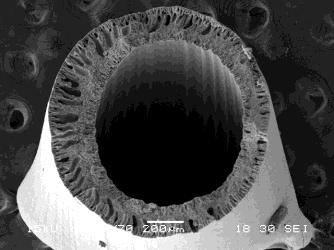


113 HS1 Outer surface Inner surface HS2 Outer surface Inner surface HS3 Outer surface Inner surface HS4 Outer surface Inner surface Figure SEM images of the cross-sections and inner and outer surfaces of samples HS1-HS4 111


114 HSB1 Outer surface Inner surface HSB2 Outer surface Inner surface HSB3 Outer surface Inner surface HSB4 Outer surface Inner surface Figure SEM images of the cross-sections and inner and outer surfaces of samples HSB1-HSB4 112


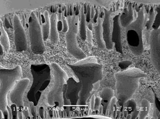


115 HSC1 Outer surface Inner surface HSC2 Outer surface Inner surface HSC3 Outer surface Inner surface HSC4 Outer surface Inner surface Figure SEM images of the cross-sections and inner and outer surfaces of samples HSB1-HSB4 113
116 Contact angle ( ) Surface hydrophilicity of the hollow fibres (contact angle measurement) The sessile drop method was used to measure the water contact angle as an indication of hollow fibre surface hydrophilicity and the results are presented in Figure As expected, contact angle values of samples S1-S4 are higher than 85 because of the hydrophobic nature of the PVDF. The contact angle for all of the samples with copolymer was lower than 85, which indicated that the surface hydrophilicity of the fibres had improved. It seems that the extrusion rate did not have a significant effect on surface hydrophilicity in samples HS1-HS4 and HSB1-HSB4. However a slight change in the contact angle can be observed for samples HSC1-HSC4. By increasing the extrusion rate, contact time with the air for the outer surface of the as-spun polymer would be shorter, which may have improved surface segregation. Samples HS1-HS4 exhibited lower contact angle values compared to samples HSB1-HSB4 and HSC1-HSC4. This could be the result of lower viscosity and consequently more effective surface segregation S1 S2 S3 S4 Sample Figure Contact angle measurement for PVDF hollow fibres with low content of PVDF-g-POEM 114 HS1 HS2 HS3 HS4 HSB1 HSB2 HSB3 HSB4 HSC1 HSC2 HSC3 HSC4
117 Filtration performance The results of filtration performance including pure water flux, dextran MWCO, BSA rejection and water flux recovery after washing the module with water are summarised in Table 3.7. Table 3.7. Water flux, dextran MWCO, BSA rejection and water flux recovery for hydrophilic PVDF hollow fibre membranes. Sample Pure Water Flux (L.m -2.h -1 ) Dextran MWCO (kda) BSA rejection (%) Flux recovery (%) S1 0.3± S2 0.3± S3 0.2± S4 0.2± HS ± ± ±1.6 HS ± ± ±2.1 HS ± ± ±1.4 HS ± ± ±3.1 HSB ± ± ±1.4 HSB ± ± ±1.8 HSB ± ± ±1.3 HSB ± ± ±0.7 HSC ± ± ±1.2 HSC ± ± ±1.6 HSC ± ± ±2.4 HSC ± ± ±3.1 As expected, pure water flux for pure PVDF hollow fibre membranes was very low. Therefore other tests such as MWCO, BSA rejection and flux recovery were not performed for samples S1-S4. Compared to pure PVDF membranes, using PVDF-g-POEM as a blend to produce hollow fibres, significantly improved the pure water flux. As a general trend, by increasing the extrusion rate, water flux and MWCO increased. This could be due to the higher lumen porosity (as observed from the SEM images) and/or more effective surface segregation for samples HSC1-HSC4. Sample HSB4 had the highest water flux of (L.m -2.h -1 ) with dextran MWCO of 500 (kda) and HSC2 had the lowest water flux of 105 (L.m -2.h -1 ) with dextran MWCO of 150 (kda). The low MWCO for samples HSC1-115
118 HSC3 could be due to the higher air gap (explained above) and/or the higher amount of PVDF in the spinning dope. All the samples exhibited water flux recovery higher than 94% after washing with water and it seemed that the spinning parameters did not have a significant effect on flux recovery. The results suggested that the hydrophilic PVDF samples provided high fouling resistance Mechanical properties As previously mentioned, by increasing the extrusion rate the chains become more oriented along the fibre length and more compact, which increases the maximum load that the fibre can withstand. On the other hand, since polymer chains in the compact structure cannot move, elongation decreases. Table 3.8 shows the mechanical properties for PVDF hollow fibres with low contents of PVDF-g-POEM. Table 3.8. Mechanical properties for the PVDF hollow fibres with low contents of PVDF-g-POEM Sample Maximum Load (N) Maximum Stress (MPa) Elongation (%) S1 1.3± ±11.2 S2 2.5± ±10.5 S3 2.7± ±7.3 S4 3.0± ±9.5 HS1 1.3± ±6.4 HS2 1.8± ±8.5 HS3 1.8± ±6.5 HS4 1.8± ±5.6 HSB1 1.2± ±9.6 HSB2 1.7± ±7.3 HSB3 1.6± ±8.1 HSB4 1.9± ±9.6 HSC1 1.2± ±8.6 HSC2 1.8± ±11.4 HSC3 2.3± ±12.7 HSC4 2.3± ±
119 Using PVDF-g-POEM as a blend in PVDF membranes causes macro-voids and large finger-like pores to form, which results in reduced mechanical strength and elongation in hollow fibres. As seen from the table, samples S1-S4, which were pure PVDF membranes, showed excellent maximum stress and a very high elongation. By increasing the extrusion rate, due to improved packing of the polymer chains, the maximum load increased. However, wall thickness increased at the same time, meaning that this trend could not be clearly differentiated from fibre s maximum stress. Nevertheless, this trend of decreasing elongation by increasing extrusion rate can clearly be seen from Table Effect of addition of high contents of PVDF-g-POEM on the membrane properties In order to improve the hydrophilic PVDF hollow fibres the effect of blending large amounts of PVDF-g-POEM was also investigated and hollow fibres with pure PVDFg-POEM was also produced Spinning dope preparation The spinning parameters for samples with high amounts of PVDF-g-POEM blends are presented in Table 3.9. The spun hollow fibres were post-treated and characterised in a similar way to previous procedures Hollow fibre characterisations SEM micrographs SEM images of cross-sections and inner and outer surfaces of samples HC1-HC4, COP1 and COP2 are presented in Figures The morphological structure of sample HC1 is shown in Figure HC1 had macro-voids at the lumen and shell sides of the membrane and such macro-voids known to form through a rapid coagulation process. However, a dense, sponge-like layer existed in the 117
120 middle. Although the dope viscosity was increased, since the amount of the copolymer was increased at the same time, the macro-voids formed, but compared to membranes with low contents of PVDF-g-POEM, the size of the macro-voids seemed reduced, which could be due to the higher dope viscosity. The SEM images of the morphological structure of samples HC2 and HC3 are presented in Figure Both samples showed crystal structures, thus lowering their degree of elongation. This suggested that liquid-liquid demixing was suppressed during the precipitation process, and crystallisation was dominant. Since PVDF is a semi crystalline polymer, it may have undergone both liquid-liquid demixing and solid-liquid demixing (crystallisation). Crystallisation is likely to be affected by kinetic factors, such as temperature and spinning parameters [42]. HC2 exhibited an asymmetric structure with larger macro-voids at the lumen side. These macro-voids appeared to be inward-pointing macro-voids. According to Widjojo and Chung [43], such macro-voids are generally caused by local surface instability, skin rupture and convective flow throughout the coagulation process. During coagulation, the solvent from the casting solution depletes rapidly when the non-solvent coagulant intrudes. Thus, while the semi coagulated membrane skin contracts and reseals the intrusion points (as a result of fluid elasticity), macro-voids are formed because of the nucleation of depleted solvent in the polymer-lean phase.. 118
121 Table 3.9. Spinning parameters of the PVDF hollow fibres with high amounts of PVDF-g-POEM Sample PVDF PVDF-g-POEM Dope Viscosity Extrusion Rate Bore Fluid Bore fluid rate Air Gap (wt.%) (wt.%) (cp) (ml/min) (v%) (ml/min) (cm) HC ± Water HC ± Water HC ± % DMAc/water HC ± Water Cop ± Water Cop ± % DMAc/water


122 HC1 Outer surface Inner surface Figure SEM images of cross-sections and inner and outer surfaces of sample HC1 HC3 exhibited finger-like structures spanning the inner and outer layers of the membrane. This could be the effect of the internal coagulant, which contained a mixture of solvent and water instead of pure water. A solvent containing internal coagulant could aggravate the rapid diffusion/depletion of the solvent within the dope composition and bore fluid, thus rupturing the polymer-lean nuclei, resulting in larger macro-voids. In addition, pores were observed on the inner layer surface. This was the result of tension from the existence of crystal structures through the crystallisation of PVDF. Pores were not observed at the outer layer as the slower coagulation rate allowed the polymeric chains to have more time to relax and reorientate themselves [44]. 120


123 HC2 Outer surface Inner surface HC3 Outer surface Inner surface Figure SEM images of cross-sections and inner and outer surfaces of samples HC2 and HC3 The structure of HC4 is illustrated in Figure 3.18, which exhibited an asymmetric structure. With 15% of copolymer in the dope solution, this sample showed finger- like structures but, HC4 did not have crystals; hence its elongation was higher than samples HC2 and HC3. Inward-pointing macro-voids were observed at the inner layer but, in contrast to HC2 and HC3, showed inward- pointing finger- like structure emerging from the shell side of the membrane. Generally, such macro-voids are caused by non-solvent intrusion as a result of liquid- liquid demixing, an outer membrane skin rupture and instability of the local surface [43]. 121


124 Increasing the PVDF concentration from 15 to 27 wt.% and simultaneously decreasing the copolymer concentration from 15 to 9 wt.% highlighted changes in membrane morphology. As the PVDF/PVDF--g- POEM composition ratio changed from 1:1 to 3:1, inner and outer macro-void formation was suppressed. There was also a structural transition from large macro fingers on the inner and outer membrane layer to smaller macro-voids on the inner and outer layer, with a sponge--like layer in the middle. However, as the PVDF/PVDF- g- POEM ratio reached 3:1, macro-void formation was no longer suppressed and they span from the inner and outer surfaces of the membrane. Macro-void suppression can be explained by the increase in dope viscosity, thus reducing the exchange rates of solvent and non-solvent and leading to greater diffusion resistance from polymer aggregation. This phenomenon was also observed by Yuliwati and Ismail [45]. In addition, the decrease in the amount of copolymer meant that there were less hydrophilic components in the membrane, thus lowering the solvent/non-solvent exchange rate and resulting in a more sponge-like structure. HC4 Outer surface Inner surface Figure SEM images of cross-sections and inner and outer surfaces of sample HC4 On the other hand, by increasing the polymer/copolymer ratio to 3:1, the presence of finger-like structures in the membrane increased. However, despite the 122
125 higher viscosity in HC2 and HC3, macro-voids were not reduced. This could be the effect of the high amounts of hydrophilic components in the spinning dope and increased affinity to water, which caused fast liquid-liquid demixing. Another reason could be the short air gap length (4 cm with HC3). In general, a greater air gap length suppresses macro-void formation and promotes a denser sponge-like membrane structure, because the fibre diameter shrinks rapidly during spinning, due to the elongational stress and resulting in tighter molecular packing. With a shorter air gap length, the fibre is immersed in the non-solvent coagulation bath almost immediately after exiting the spinneret, which results in a less oriented and looser polymeric chain interaction, thus giving rise to macro-voids [46]. Although HC2 had a relatively larger air gap length (20 cm), macro-voids were not reduced, which could be due to the reorientation of the polymer molecules into the crystalline lattice, resulting in disruption of local surface stability to bring about rupture and macro-void formation. The pure copolymer membranes did not have macro-voids (Figures 3.19) and a few factors may have contributed to such a structure, including 1) critical polymer concentration/composition, 2) critical air gap length, and 3) critical spinning dope viscosity. These factors work together, leading to tightly packed polymer chains and ultimately resulting in finger free membrane structures [47]. Moreover, samples COP1 and COP2 exhibited crack-like structures, which could have arisen from surface instability and skin rupture of the membrane during the coagulation process, as the viscosity of the dope solution was not very high. Another reason behind such a structure could be the homogenous hydrophilicity of the dope solution, the dope was prepared from one amphiphilic component and not a hydrophobic component added to the solution. 123


 The")


126 COP1 Outer surface Inner surface COP2 Outer surface Inner surface Figure SEM images of cross-sections and inner and outer surfaces of samples COP1-COP Surface hydrophilicity of hollow fibres (contact angle measurement) The contact angle values for each hollow fibre, measured by using sessile drop method, are shown in Figure As seen in Figure 3.20, all of the hollow fibres had contact angles of less than 75 due to the copolymer blend, for instance, samples HC1-HC4 had contact angles in the range of In general, contact angle is dependent on a number of factors, such as surface hydrophilicity/hydrophobicity, pore size, pore size distribution and surface roughness [48]. In addition, a dense top layer was observed in the SEM micrographs, which results in a higher contact angle value. The pure copolymer membranes had the smallest contact angles, indicating that they were more hydrophilic than the PVDF/copolymer blend membranes. 124
127 Contact angle ( ) HC1 HC2 HC3 HC4 COP1 COP2 Sample Figure Contact angle values for samples HC1-HC4, COP1 and COP2 The results also showed that as the amount of PVDF increased, the contact angle increased. The contact angle decreased with a higher proportion of copolymer in the spinning dope solution. Since the copolymer is amphiphilic, increasing the amount of copolymer in the solution will increase surface hydrophilicity. As PVDF is hydrophobic, a higher amount of PVDF in the membrane will decrease hydrophilicity of the membrane surface Filtration performance The pure water flux, dextran MWCO, BSA rejection and water flux recovery values for samples HC1-HC4, COP1 and COP2 are summarised in Table These membranes exhibited relatively lower water flux and very low MWCO compared to those with low contents of PVDF-g-POEM, which could be due to a dense layer formation resulting from a high copolymer content. The results illustrate that samples COP1 and COP2 showed a very low water flux with a very low MWCO. All of the samples had BSA rejection higher than 90% suggesting that these membranes are suitable for a very tight ultrafiltration processes. Due to the surface 125
128 hydrophilicity, the flux recovery of the samples was higher than 95% after washing with water indicating that the fouling resistance of the hollow fibres significantly improved. Table Pure water flux, dextran MWCO, BSA rejection and water flux recovery values for samples HC1-HC4, COP1 and COP2 Dextran MCWCO (kda) BSA rejection (%) Flux recovery (%) Sample Water Flux (L.m -2.h -1 ) HC ± > ±2.4 HC ± > ±1.7 HC ± > ±2.6 Hc7 6.42±1.3 6 > ±0.6 Cop ±2.9 6 > ±2.7 Cop ±4.7 6 > ± Mechanical properties The mechanical properties of samples HC1-HC4, COP1 and COP2 are summarised in Table As can be seen from Table 3.11, samples HC2 and HC3 exhibited very low elongation due to their crystalline structure; nevertheless sample HC2 showed maximum stress of about 5.5 MPa, which indicated that the crystals were connected. Samples COP1 and COP2 showed excellent elongations of 684 % and 568 %, respectively. The range of the stress and elongation suggested that the samples were suitable for low pressure filtration processes such as ultrafiltration, except for samples HC2 and HC3. Table Mechanical properties of samples HC1-HC4, COP1 and COP2 Sample Maximum Load (N) Maximum Stress (MPa) Elongation (%) HC1 1.7± ±11.5 HC2 2.0 ± ±8.6 HC3 0.9± ±6.4 HC4 1.3± ±10.1 COP1 1.1± ±14.1 COP2 0.8± ±
129 3.7 Conclusions The amphiphilic copolymer PVDF-g-POEM was synthesised using a newly developed ATRP method. The new and simplified method was introduced to purify and dry the copolymer using water instead of volatile and toxic solvents. The purified copolymer was blended with the spinning dope to produce modified PVDF hollow fibre membranes. The surface composition and contact angle measurements of the prepared hollow fibres using the amphiphilic copolymer as the blend showed that hydrophilicity of the membrane surface was significantly improved. The modified hollow fibres exhibited water flux of and L.m -2.h -1 with a dextran MWCO of 200 kda for samples H1 and H2, respectively at a transmembrane pressure of 1 bar, which suggested that they were suitable for ultrafiltration. Flux recovery of over 95% after flux decline due to protein circulation was achieved by washing the membranes with water illustrating that the fouling resistance of the modified hollow fibre membranes improved considerably. The effect of the spinning process on hydrophilic PVDF membranes with low contents of PVDF-g-POEM (5-6%) was also studied. The results indicated that by increasing the extrusion rate, polymer chain orientation and chain compaction increased resulting in increased maximum stress of the fibre and decreased elongation. Moreover, by increasing the extrusion rate, the wall thickness of the fibre increased and due to the tension inside the spinneret, porosity of the lumen side increased. By mixing solvent in the internal coagulant, the finger-like pores from the inner layer changed to sponge-like pores and by changing the spinning parameters, a wide range of hydrophilic hollow fibres was obtained with water fluxes from (L.m -2.h -1 ) and dextran MWCO of 500 (kda) (sample HSB4) to 105 (L.m -2.h -1 ) and 127
130 dextran MWCO of 150 (kda)(sample HSC2). The hydrophilicity of all the hollow fibres with a blend of PVDF-g-POEM improved. The effect of the presence of a high PVDF-g-POEM content (7-100%) on the morphology and properties of the hydrophilic PVDF membrane was also investigated. The hydrophilicity of the resultant membranes improved, but, possibly due to the formation of dense skin layers, water flux was not high. Nevertheless, the very low MWCO, along with high water flux recovery after washing the module with water (higher than 95%) suggested that these membranes were suitable for very tight ultrafiltration processes. In general, by adding PVDF-g-POEM to the PVDF spinning dope, the hydrophilicity, water flux and fouling resistance of the produced hollow fibres improved. By changing the copolymer contents, internal coagulant composition and spinning parameters, a wide range of PVDF-based hollow fibres in the range of very tight to loose ultrafiltration membranes were obtained. 128
131 3.8 References [1] S.P. Deshmukh, K. Li, Effect of ethanol composition in water coagulation bath on morphology of PVDF hollow fibre membranes, Journal of Membrane Science, 150 (1998) [2] D.L. Wang, W.K. Teo, K. Li, Selective removal of trace H 2 S from gas streams containing CO 2 using hollow fibre membrane modules/contractors, Separation and Purification Technology, 35 (2004) [3] D. Wang, K. Li, W.K. Teo, Preparation and characterization of polyvinylidene fluoride (PVDF) hollow fiber membranes, Journal of Membrane Science, 163 (1999) [4] S. Munari, A. Bottino, G. Capannelli, Casting and performance of polyvinylidene fluoride based membranes, Journal of Membrane Science, 16 (1983) [5] M.L. Yeow, Y.T. Liu, K. Li, Morphological study of poly(vinylidene fluoride) asymmetric membranes: Effects of the solvent, additive, and dope temperature, Journal of Applied Polymer Science, 92 (2004) [6] K.H. Oshima, T.T. EvansStrickfaden, A.K. Highsmith, E.W. Ades, The use of a microporous polyvinylidene fluoride (PVDF) membrane filter to separate contaminating viral particles from biologically important proteins, Biologicals, 24 (1996) [7] B. Wu, K. Li, W.K. Teo, Preparation and characterization of poly(vinylidene fluoride) hollow fiber membranes for vacuum membrane distillation, Journal of Applied Polymer Science, 106 (2007) [8] M.L. Yeow, R.W. Field, K. Li, W.K. Teo, Preparation of divinyl-pdms/pvdf composite hollow fibre membranes for BTX removal, Journal of Membrane Science, 203 (2002) [9] H.H. Park, B.R. Deshwal, H.D. Jo, W.K. Choi, I.W. Kim, H.K. Lee, Absorption of nitrogen dioxide by PVDF hollow fiber membranes in a G-L contactor, Desalination, 243 (2009) [10] M. Khayet, K.C. Khulbe, T. Matsuura, Characterization of membranes for membrane distillation by atomic force microscopy and estimation of their water vapor transfer coefficients in vacuum membrane distillation process, Journal of Membrane Science, 238 (2004) [11] X. Tan, S.P. Tan, W.K. Teo, K. Li, Polyvinylidene fluoride (PVDF) hollow fibre membranes for ammonia removal from water, Journal of Membrane Science, 271 (2006) [12] F. Liu, N.A. Hashim, Y. Liu, M.R.M. Abed, K. Li, Progress in the production and modification of PVDF membranes, Journal of Membrane Science, 375 (2011)
132 [13] A. Bottino, G. Capannelli, S. Munari, A. Turturro, High-performance ultrafiltration membranes cast from LiCl doped solutions, Desalination, 68 (1988) [14] D.J. Lin, C.L. Chang, F.M. Huang, L.P. Cheng, Effect of salt additive on the formation of microporous poly(vinylidene fluoride) membranes by phase inversion from LiClO 4 /water/dmf/pvdf system, Polymer, 44 (2003) [15] X. Cao, J. Ma, X. Shi, Z. Ren, Effect of TiO 2 nanoparticle size on the performance of PVDF membrane, Applied Surface Science, 253 (2006) [16] L. Yan, Y.S. Li, C.B. Xiang, Preparation of poly(vinylidene fluoride)(pvdf) ultrafiltration membrane modified by nano-sized alumina (Al 2 O 3 ) and its antifouling research, Polymer, 46 (2005) [17] F. Liu, M.R.M. Abed, K. Li, Preparation and characterization of poly(vinylidene fluoride) (PVDF) based ultrafiltration membranes using nano gamma-al 2 O 3, Journal of Membrane Science, 366 (2011) [18] A. Bottino, G. Capannelli, A. Comite, Preparation and characterization of novel porous PVDF-ZrO 2 composite membranes, Desalination, 146 (2002) [19] A. Bottino, G. Capannelli, V. D'Asti, P. Piaggio, Preparation and properties of novel organic-inorganic porous membranes, Separation and Purification Technology, 22-3 (2001) [20] S.-R. Chae, H. Yamamura, K. Ikeda, Y. Watanabe, Comparison of fouling characteristics of two different poly-vinylidene fluoride microfiltration membranes in a pilot-scale drinking water treatment system using pre-coagulation/sedimentation, sand filtration, and chlorination, Water Research, 42 (2008) [21] J.R. Du, S. Peldszus, P.M. Huck, X. Feng, Modification of poly(vinylidene fluoride) ultrafiltration membranes with poly(vinyl alcohol) for fouling control in drinking water treatment, Water Research, 43 (2009) [22] T. Uragami, Y. Naito, M. Sugihara, Studies on synthesis and permeability of special polymer membranes.39. Permeation characteristics and structure of polymer blend membranes from poly(vinylidene fluoride) and poly(ethylene glycol), Polymer Bulletin, 4 (1981) [23] S. Inceoglu, S.C. Olugebefola, M.H. Acar, A.M. Mayes, Atom transfer radical polymerization using poly(vinylidene fluoride) as macroinitiator, Designed Monomers and Polymers, 7 (2004) [24] J.F. Hester, P. Banerjee, Y.Y. Won, A. Akthakul, M.H. Acar, A.M. Mayes, ATRP of amphiphilic graft copolymers based on PVDF and their use as membrane additives, Macromolecules, 35 (2002) [25] A. Akthakul, R.F. Salinaro, A.M. Mayes, Antifouling polymer membranes with subnanometer size selectivity, Macromolecules, 37 (2004)
133 [26] A. Bottino, G. Capannelli, O. Monticelli, P. Piaggio, Poly(vinylidene fluoride) with improved functionalization for membrane production, Journal of Membrane Science, 166 (2000) [27] L. Cen, K.G. Neoh, L. Ying, E.T. Kang, Surface modification of polymeric films and membranes to achieve antibacterial properties, Surface and Interface Analysis, 36 (2004) [28] P. Wang, K.L. Tan, E.T. Kang, K.G. Neoh, Plasma-induced immobilization of poly(ethylene glycol) onto poly(vinylidene fluoride) microporous membrane, Journal of Membrane Science, 195 (2002) [29] Y.-H. Zhao, Y.-L. Qian, B.-K. Zhu, Y.-Y. Xu, Modification of porous poly(vinylidene fluoride) membrane using amphiphilic polymers with different structures in phase inversion process, Journal of Membrane Science, 310 (2008) [30] J.F. Hester, P. Banerjee, A.M. Mayes, Preparation of protein-resistant surfaces on poly(vinylidene fluoride) membranes via surface segregation, Macromolecules, 32 (1999) [31] J.F. Hester, A.M. Mayes, Design and performance of foul-resistant poly(vinylidene fluoride) membranes prepared in a single-step by surface segregation, Journal of Membrane Science, 202 (2002) [32] K. Matyjaszewski, J.H. Xia, Atom transfer radical polymerization, Chemical Reviews, 101 (2001) [33] N.A. Hashim, F. Liu, K. Li, A simplified method for preparation of hydrophilic PVDF membranes from an amphiphilic graft copolymer, Journal of Membrane Science, 345 (2009) [34] F. Liu, M.R.M. Abed, and K. Li, Hydrophilic modification of P(VDF-co-CTFE) porous membranes, Chemical Engineering Science, 66 (2011) [35] P. Wang, K.L. Tan, E.T. Kang, K.G. Neoh, Synthesis, characterization and antifouling properties of poly(ethylene glycol) grafted poly(vinylidene fluoride) copolymer membranes, Journal of Materials Chemistry, 11 (2001) [36] F. Liu, C.-H. Du, B.-K. Zhu, Y.-Y. Xu, Surface immobilization of polymer brushes onto porous poly(vinylidene fluoride) membrane by electron beam to improve the hydrophilicity and fouling resistance, Polymer, 48 (2007) [37] H. Strathmann, K. Kock, P. Amar, R.W. Baker, The formation mechanism of asymmetric membranes, Desalination, 16 (1975) [38] M. Mulder, Basic Principles of Membrane Technology, Kluwer Academic Publishers, Dordrecht, London: Kluwer
134 [39] J. Ren, R. Wang, H.Y. Zhang, Z. Li, D.T. Liang, J.H. Tay, Effect of PVDF dope rheology on the structure of hollow fiber membranes used for CO 2 capture, Journal of Membrane Science, 281 (2006) [40] M.L. Yeow, Y.T. Liu, K. Li, Preparation of porous PVDF hollow fibre membrane via a phase inversion method using lithium perchlorate (LiClO 4 ) as an additive, Journal of Membrane Science, 258 (2005) [41] N. Peng, T.-S. Chung, K.Y. Wang, Macro-void evolution and critical factors to form macro-void-free hollow fiber membranes, Journal of Membrane Science, 318 (2008) [42] M.G. Buonomenna, P. Macchi, M. Davoli, E. Drioli, Poly(vinylidene fluoride) membranes by phase inversion: the role the casting and coagulation conditions play in their morphology, crystalline structure and properties, European Polymer Journal, 43 (2007) [43] N. Widjojo, T.-S. Chung, Thickness and air gap dependence of macro-void evolution in phase-inversion asymmetric hollow fiber membranes, Industrial & Engineering Chemistry Research, 45 (2006) [44] B.J. Cha, J.M. Yang, Preparation of poly(vinylidene fluoride) hollow fiber membranes for microfiltration using modified TIPS process, Journal of Membrane Science, 291 (2007) [45] E. Yuliwati, A.F. Ismail, Effect of additives concentration on the surface properties and performance of PVDF ultrafiltration membranes for refinery produced wastewater treatment, Desalination, 273 (2011) [46] M. Khayet, The effects of air gap length on the internal and external morphology of hollow fiber membranes, Chemical Engineering Science, 58 (2003) [47] N. Peng, T.S. Chung, K.Y. Wang, Macro-void evolution and critical factors to form macro-void-free hollow fiber membranes, Journal of Membrane Science, 318 (2008) [48] D. Rana, T. Matsuura, R.M. Narbaitz, C. Feng, Development and characterization of novel hydrophilic surface modifying macromolecule for polymeric membranes, Journal of Membrane Science, 249 (2005)
135 CHAPTER 4 Fabrication of PVDF ultrafiltration membrane using nano γ-al 2 O 3 as an additive 4.1 Abstract PVDF based ultrafiltration membranes were prepared from a PVDF/nano γ-al 2 O 3 complex suspension where the γ-al 2 O 3 was well-dispersed and the effect of nano γ-al 2 O 3 concentration on membrane performances was investigated. Surface chemical compositions, surface and cross-section morphologies, and hydrophilicity of the membranes were characterised by Fourier transform infrared spectroscopy (FTIR), differential scanning calorimeter (DSC), scanning electron microscopy (SEM) and contact angle measurement, respectively. The mechanical strength of the membranes was also investigated. Permeation experiments were conducted to evaluate the water flux. Both static and dynamic BSA fouling resistance performances were investigated. All of the experimental results indicated that the new PVDF ultrafiltration membranes demonstrated better separation performances than pure PVDF membranes. 4.2 Introduction Modification of PVDF membranes has been extensively investigated to improve hydrophilicity and fouling resistance. Surface modification and blending techniques are mostly adapted due to their versatile controlling conditions. Surface modification methods include plasma [1-3], UV [4-7], electron beam surface induced grafting polymerisation [8-11], and surface living/controlled radical polymerisation [12-18]. Blending methods usually involve some amphiphilic copolymers, which need to be synthesised elaborately through ATRP [19-21] or reversible additionfragmentation chain transfer polymerisation (RAFT) [3, 22] living/controlled radical polymerisation. Besides the amphiphilic copolymers, inorganic particles, such as 133
136 Al 2 O 3, SiO 2, TiO 2, ZrO 2, Fe 3 O 4, LiOCl 4 and CdS, were also blended in the PVDF solution in fabricating organic/inorganic hybrid membranes. Among these inorganic materials, Al 2 O 3 particles received much attention due to their stability, availability, hydrophilicity and suitable mechanical strength. However, most of studies focused on the physical blending of Al 2 O 3, which highlighted a potential problem in that Al 2 O 3 particles may not be well dispersed in the polymer solution even at low concentrations. Particle segregation may take place during the preparation, resulting in poor performances of the resultant membranes. Nano γ-al 2 O 3 particles were of particular interest due to their surface activity, high adsorptive ability and surface enrichment of reactive functional hydroxyl groups, which can further endow the membrane with enhanced hydrophilicity and fouling resistance. It has been shown that PVDF is resistant in acid, but susceptible in strong alkali solutions, such as concentrated sodium hydroxide [17, 23] due to the formation of conjugated double bonds, resulting in a visual change in colour from white to yellow and then dark brown and final disintegration of the membrane. However, a suitable alkaline environment can be adjusted to design PVDF membranes with desirable properties such as hydrophilicity, good fouling resistance and filtration performances [24]. In this study, it was demonstrated that a small amount of basic nano γ- Al 2 O 3 particles could directly modify the PVDF chain by a grafting reaction without adding extra alkaline. In addition, the reaction between γ-al 2 O 3 particles, containing substantial amount of hydroxyl groups (OH - ), and PVDF could be catalysed by some acids. Thus, a stable PVDF/nano γ-al 2 O 3 complex solution could be obtained according to the suggested mechanism shown in Figure
137 CF 2 CH 2 n OH - basic -alumina CF 2 CH 2 CF CH n n H + F C H CH n -Al 2 O 3 -OH F CF 2 CH 2 x C CH H y -Al 2 O 3 -O Figure 4.1. Scheme of reaction between γ-al 2 O 3 and PVDF during the preparation of complex suspension It was envisaged that by controlling the amount of the PVDF/ nano-γ- Al 2 O 3 complex in the bulk PVDF solution, a hydrophilic and anti-fouling PVDF ultrafiltration membrane could be prepared in one step via a conventional phase inversion technique because the hydrophilic PVDF/nano-γ-Al 2 O 3 complex can be segregated onto the membrane surface during the immersion step. The surface chemical compositions, morphologies, porosities, hydrophilicity and mechanical strength of the resultant membranes were investigated and the flux and filtration performances were also examined in details. 4.3 Experimental Materials Commercial PVDF (Kynar K-761) was dried at 60 C for 24 hours before use and γ-al 2 O 3 particles (20nm, 99+%) were purchased from Alfa Aesar. 1- methyl-2-pyrrolidinone (NMP) was purchased from Sigma Aldrich. Sulphuric acid (H 2 SO 4 ) was obtained from VWR International Ltd. UK. Bovine serum albumin (BSA Fraction V, Mn=67,000) and phosphate-buffered saline (PBS solution, ph=7.4) were purchased from Sigma Aldrich, UK. All other chemicals, unless otherwise stated, were obtained from commercial sources and used as received. 135
138 4.3.2 Preparation of complex solution and membrane PVDF Polymer was dissolved in NMP (15%) at 70 C and stirred for 24 hours to obtain a homogenous PVDF solution (60 g). Different amounts (0%, 1%, 2% and 4% based on the solution weight) of γ-alumina was added to the PVDF solution and the mixture was stirred for 24 hours at 70 C until a uniform purple-pink suspension was obtained. Then sulphuric acid (7.5 g, 98%) was added and the mixture was stirred at 70 C until the colour of the solution disappeared and the final complex solution was obtained. The complex solution was then cast onto a glass plate to produce a flat sheet membrane via the phase inversion method. The fabricated membrane was immersed into fresh de-ionized water to remove all the residual solvent before all characterizations. The wet membrane was directly used to measure the filtration performance. The remaining membrane was dried in the air at room temperature for other characterizations. Tables 4.1 and 4.2 show the compositions of each mixture and membrane casting parameters, respectively. Sample. Table 4.1. PVDF/γ-Al 2 O 3 membranes with different composition PVDF (wt.%) NMP (wt.%) γ-alumina 1 (wt.% ) 1: The percentage of γ Alumina is based on the total amount of PVDF solution (60g) H 2 SO 4 (g) M M M M
139 Table 4.2. Casting parameters for flat sheet membranes Casting thickness 150μm Casting Temp. 20ºC Casting speed 4cm/s Evaporation time 5s Coagulation bath DI water Coagulation bath Temp. 20ºC Membrane characterisations Viscosity of the complex solution was measured by rheometer (Physica, UDS200) at shear rates of between 0.1 S -1 and 100 S -1 prior to the membrane casting. Fourier transform infrared attenuated total reflection (FTIR-ATR) spectrometer (Perkin Elmer) was used to detect chemical compositions of the membrane s top surface before and after acid treatment. The samples were placed on the sample holder and all spectra were recorded in the wave number range of cm -1 by cumulating 32 scans at a resolution of 2 cm -1. The thermal behaviour of the membrane was determined using a differential scanning calorimeter (DSC) (Pyris-1, Perkin Elmer, Beaconsfield, UK). To achieve a near-equilibrium structure prior to DSC analysis, the samples were preconditioned in the calorimeter by heating from 25 C to 250 C at 10 C/min, holding at 250 C for 10 minutes, cooling to 25 C at 10 C/min and then heating from 25 C to 250 C at 10 C/min. DSC thermograms were then obtained for the last cycle. Morphological structures of the prepared PVDF membranes were examined by scanning electron microscope (SEM, JSM-5610LV, JEOL, Tokyo, 137
140 Japan). The cross-section samples were fractured in liquid nitrogen. Both the surface and cross-section of the samples were gold sputtered for 3 minutes before observation. The mechanical properties of the membranes were determined using a tensile tester (Instron-4466) with a stretching rate of m/s at room temperature (20 C). Each sample was cut into 10 cm 2cm, and the thickness of the sample was measured according to the SEM pictures. The hydrophilicity of the membrane was determined by measuring the contact angle of the membrane top surface. To achieve the real hydrophilicity of the porous membrane, the contact angle change with the drop age was recorded using the Drop Shape Analyser (DSA 10 MK2, Krüss GmbH, Hamburg, Germany). Water permeation of the membrane was measured in a circular 5 cm dead end filtration cell. The measuring protocol was as follows: the membrane was compacted at 1.5 bar to get a steady flux for the first 40 minutes; then the flux was recorded at 1 bar every 5 minutes, with at least 5 readings collected to obtain an average value. Thereafter, pure water was changed to a 0.1g/L BSA solution in PBS (ph=7.4) and the permeate flux profile with time was recorded to determine the dynamic fouling resistance of the membrane. BSA concentrations of both the feed and permeate solution were measured by UV-VIS spectrophotometer (UV-2101PC, Shimadzu, UK) at 280 nm. The rejection of BSA was calculated using the following equation: A0 R (%) (1 ) 100 Eq. 4.1 A 1 where A 1 is the absorption value of the feed solution, and A 0 is the absorption value of the permeate solution. 138
141 For the static adsorption fouling experiment, the membrane was immersed in a solution of BSA/PBS (1g/L, ph=7.4) and stirred for 24 hours. Thereafter, the membrane was removed and rinsed with water for a few seconds and repeated twice. Then, the recovered water flux, J 1 was measured again. The evaluation of membrane performance was expressed in term of the relative flux reduction (RFR) as follows: J1 RFR (%) (1 ) 100 Eq. 4.2 J 0 To wash away γ-al 2 O 3 particles that were physically blended with the membrane, an acid washing (sulphuric acid for 5 hours) followed by soaking in water (for 1 hour) was performed. SEM micrographs and pure water flux were obtained before and after acid washing. 4.4 Results and discussion In this study, it is important to mention that the basic γ-al 2 O 3 particles should be added in the PVDF solution prior to the acid. This would result in the solution changing colour from milky white to yellow, and then to dark brown (depending on the amount of γ-al 2 O 3 ), which indicates the formation of conjugated double bonds on the PVDF main chains. Afterwards, a suitable amount of sulphuric acid should be added to the complex and stirred for 24 hours until the yellow (or brown) colour disappears, representing the evidence of unsaturated doubles reacting with the OH groups of the γ-al 2 O 3. The mechanism of the reaction to form the complex was suggested and is shown in Figure 4.1, in which it can be seen that the basic γ-al 2 O 3 with free OH - ions provides the alkaline environment necessary for this reaction. The electrophilic addition is catalysed by the sulphuric acid and 139
142 acidification of the unsaturated double generates a cation, to which the γ-al 2 O 3 with hydroxyl groups is grafted onto the main chain of PVDF Casting solution and membrane surface properties A minor amount (less than 4%) of γ-al 2 O 3 can increase the viscosity of the complex and subsequently affect the structure of the resultant membrane and hence its performance. As shown in Figure 4.2, the viscosity of the complex solution increases with the amount of γ-al 2 O 3 particles. There is a possible side reaction in that the anion may displace or substitute F atom in an adjacent chain of PVDF, resulting in a crosslink. Such a crosslink could also enhance the viscosity of the complex solution. As discussed above, the unsaturated double bonds formed on the PVDF main chains in the presence of basic γ-al 2 O 3 can be confirmed by FTIR-ATR. It can be seen from Figure 4.3 that samples M1, M2 and M3 membranes before acid treatment all show a significant peak at 1643cm -1 assigned to C=C. Moreover, the OH groups at 3380cm -1 indicates the possible side reaction between C=C and water. However, the double bonds would react with γ-al 2 O 3 carrying hydroxyl groups after the addition of acid, which can be confirmed by the disappearance of double bonds at 1643cm -1 in Figure
143 Viscosity (cp) Shear rate (S -1 ) M0 M1 M2 M3 Figure 4.2. Viscosity of PVDF mixture solution with different composition (M0, M1, M2, M3) Figure 4.4 shows the FTIR-ATR of the PVDF membranes with different amounts of alumina particles. As expected, all membranes showed the main typical spectra of PVDF, i.e. CF 2 deformation and stretching vibration bonds at 1400cm -1 and 1180cm -1, β phase vibration at 1280cm -1, and amorphous phase at 880 and 840cm -1 indicating that the reaction in the complex would not damage the chemistry structure of PVDF. However, the absorption at 1643cm -1 could also be observed as a result of the formation of C=C bonds. For samples M1, M2 and M3, a significant peak at around 976cm -1 and 761cm -1 assigned to α phase vibration of PVDF has vanished, showing that the addition of alumina particles could also influence the crystalline phase of a semi-crystalline PVDF to some extent. The surface hydrophilicity of membranes could be obtained by the contact angle measurement. The initial contact angle measured immediately after water was dropped onto the membrane surface could reflect the natural wettability of the material. The initial contact angle decreases from 91.6º±1.0, to 88.4º±0.8, 81.1º 141
144 T% T% ±0.5, and 79.6º±0.6, with the amount of alumina increasing from 0% to 1%, 2% and 4%, respectively. Besides, the change in contact angle over time also demonstrated that the M3 membrane had the best hydrophilicity, probably due to the higher content of γ-al 2 O 3 particles (see Figure 4.5) M1 M2 M3 -OH C=C Wavenumber (cm -1 ) Figure 4.3. FTIR-ATR spectra of different membranes before acid treatment (M1, M2, M3) M0 M1 M2 M3 C=C Wavenumber (cm -1 ). Figure 4.4. FTIR-ATR spectra of different membranes after acid treatment (M0, M1, M2, M3) 142
145 Contact Angle (degree) M0 M1 M2 M Drop Age (S) Figure 4.5. Change of contact angle with drop age for different samples: M0, M1, M2, M Membrane morphology In order to investigate the effect of γ-al 2 O 3 nano particles on the microstructure of the membranes, SEM micrographs of both the cross-sections and surfaces of the PVDF membranes with different compositions were obtained. As seen in Figure 4.6, all of the membranes exhibited the typical asymmetric crosssectional structure, consisting of a fine thinner skin layer as a selective barrier and a much thicker, finger-like sub-structure. The top surface had a denser, nodular-like structure caused by delayed demixing during the phase inversion process. The bottom surface had a porous structure with some particles trapped inside the mechanism behind the formation of this structure has been discussed before [25]. Nevertheless, it can be seen that the thickness of the spongy layer on the membrane bottom decreased with the addition of γ-al 2 O 3 nano particles, which may have enhanced the flux of the membrane. Unexpectedly, γ-al 2 O 3 nano particles in sample M3 could not be dispersed as well as samples M1 and M2. Agglomeration phenomenon can be seen from both the cross-section and the bottom surface due to the higher concentration of γ-al 2 O 3 nano particles in sample M3. 143
146 The agglomeration of these γ-al 2 O 3 nano particles would plug the pores in both the cross-section and surface of the membrane, subsequently, influencing flux and separation performance. Comparing the top and bottom surfaces of different membranes, it can be seen that increasing the amount of alumina resulted in a higher surface porosity and the distribution of γ-al 2 O 3 nano particles. To confirm that the nano γ-al 2 O 3 particles physically blended with PVDF can be removed, the membrane was washed by sulphuric acid. Figure 4.7 illustrates the SEM micrographs of the membranes after the acid wash showing that most of the γ-al 2 O 3 particles were washed away from the top surface, bottom surfaces and cross-section. Particularly, in the case of sample M3 where some big particles trapped inside the pores could also be removed by the acid washing, which probably offered an increment of flux. Comparing Figure 4.7 with Figure 4.6, it can be seen that there were still some γ-al 2 O 3 particles in the cross-section even after a strong acid wash, suggesting a possible chemical bonded with PVDF. 144


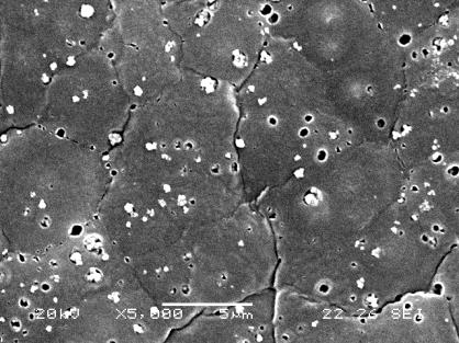


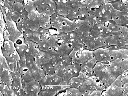
147 M0-cross M0-Top M0-bottom M1-cross M1-Top M1-bottom M2-cross M2-Top M2-bottom M3-cross M3-Top M3-bottom Figure 4.6. SEM images of cross-section of top surface and bottom surface morphology: M0, M1, M2, M3 145


148 M1-cross M1-Top M1-bottom M2-cross M2-Top M2-bottom M3-cross M3-Top M3-bottom Figure 4.7. SEM images of cross-section of top surface and bottom surface morphology for membranes after acid wash: M1, M2, M Stability of PVDF membrane The thermal stability of the PVDF membrane can be investigated by DSC measurements. Figure 4.8 shows that the melting temperature was slightly decreased according to the amount of γ-al 2 O 3 nano particles in the complex. For example, the melting temperature decreased from for pure PVDF membrane to , and for M1, M2 and M3 respectively. It could be explained that the formation of double bonds during the reaction could slightly change the main PVDF chains and subsequently influenced the melting temperature. Besides, the fusion enthalpy also decreased from J/g for sample M0 to J/g, J/g and J/g for samples M1, M2 and M3, respectively. It could be concluded that the addition of alumina had an effect on crystal perfection during the phase inversion process. Increasing the amount of γ-al 2 O 3 nano particles not only inhibited the 146
149 Hea t Flo w (W /g) formation of PVDF crystals, but also broke down the performed crystals to give the amorphous PVDF structure. 0-2 M 0 M 1 M 2 M C C C C T e m p e r a t u re ( C ) Figure 4.8. DSC thermograms for different samples (M0, M1, M2, M3) PVDF is well known for its suitable mechanical properties and it is expected that adding γ-al 2 O 3 nano particles will enhance hydrophilicity and flux without decreasing mechanical strength. As shown in Table 4.3, sample M2 had a similar tensile extension and stress to the pure PVDF membrane M0, while samples M1 and M3 had lower tensile extension and stress. This could be attributed to the competition between the dispersion of alumina particles and the amount of double bonds in the complex solution. Suitable dispersion of γ-al 2 O 3 attached to PVDF could enhance the mechanical strength to some extent; but the alkaline ions involved in basic γ-al 2 O 3 particles could cause the formation of double bonds in PVDF chains, indicating depressed mechanical strength. From the results, it can be concluded that the optimum amount of γ-al 2 O 3 in the complex solution is 2 wt.%. 147
150 Table 4.3 Different performance parameters for samples M0~M3 Sample. Elongation (%) Maximum Stress (MPa) Static CA (º) Water flux (L.m -2.h -1 ) Rejection (%) M0 97.9± ± M1 58.8± ± ± 75.0±1.5 M2 97.5± ± ± 93.4±2.2 M3 44.5± ± ± 79.3± Filtration performance The pure water flux results of different membranes are listed in Table 4.3, showing that sample M2 had the highest pure water flux of (L.m -2.h -1 ). The rejection data listed in Table 4.3 show that sample M2 had the highest BSA rejection of 93.4%. For samples M1 and M3, the water flux decreased due to either lower hydrophilicity or the agglomeration of γ-al 2 O 3 nano particles, which could plug the membrane pores. Figure 4.9 shows the pure water flux before and after acid washing. It can be seen that pure water flux increased for all three membranes. The pure flux of sample M3 increased from 79.3 (L.m -2.h -1 ) to 89.1 (L.m -2.h -1 ), which was the most considerable increment across all membranes. This is because the acid washed away most of particles trapped in the pores, which can be confirmed by SEM in Figure
151 RFR (%) Water Flux (L/m 2 h) Before acid washing After acid washing M1 M2 M3 Figure 4.9. Comparison of pure water flux before and after acid treatment for samples M1, M2, M M1 M2 M3 Sample Figure Relative flux reduction after static adsorption using BSA (1g/L, ph=7.4) for samples M1, M2, M3. The effect of γ-al 2 O 3 particles on membrane performance was investigated in terms of water flux, and static and dynamic fouling, with the relative water flux reduction (RFR) obtained to identify the extent of BSA static adsorptive fouling. As shown in Figure 4.10, Sample M2 had an RFR of 37%, indicating a higher resistance to BSA (1.0 g/l) static adsorptive fouling than samples M1 and M3. Both hydrophilicity and pore size distribution affect BSA adsorptive fouling on the membrane surface. Although sample M3 showed the highest hydrophilicity from the 149
152 contact angle results and should have had better adsorptive fouling resistance, the SEM pictures show that the pore size distribution and alumina particles dispersion of sample M3 was not uniform, which would influence BSA adsorption significantly. With these two factors, sample M2 had the best static adsorptive fouling resistance. To investigate the filtration performance, a dead-end ultrafiltration experiment was conducted. The results are presented in terms of permeate flux relative to pure water flux. From Figure 4.11, it can be seen that permeate flux dropped dramatically in the first 30 minutes and then stabilised, probably caused by concentration polarisation. After 30 minutes, sample M2 demonstrated a higher permeation flux than samples M1 and M2, which was mainly influenced by the dynamic BSA fouling. Overall, the final permeation flux of BSA for sample M2 was 60% of the initial permeation flux. This dynamic BSA anti-fouling performance concurs with static adsorptive fouling experiments M1 M2 M3 J B /J % 30% 17% Time(min) Figure Normalised flux during filtration of 0.1L/g BSA solution at 0.1MPa for samples M1, M2, M3 150
153 In general, by adding γ-al 2 O 3 particles to the PVDF solution and causing a chemical reaction between the PVDF polymer and γ-al 2 O 3 particles, certain properties of the fabricated membrane from the complex solution improved. On the other hand, by adding more γ-al 2 O 3, more alkaline was produced causing more defects to the PVDF structure and consequently depreciating the membrane performance. Therefore, there should be an optimum amount of γ-al 2 O 3 in the complex solution at which the desirable improvement in membrane properties and performance are obtained while the least degradation to PVDF chains happens. 4.5 Conclusions The PVDF ultrafiltration membrane was prepared from a complex comprising PVDF, basic γ-al 2 O 3 particles and acids via the phase inversion method. The viscosity of the complex solution increased with the addition of γ-al 2 O 3 particles, while FTIR results indicated the existence of a reaction between basic γ- Al 2 O 3 and PVDF in the complex solution. DSC showed that the melting temperature of the modified membrane decreased slightly, and SEM pictures demonstrated good dispersion of γ-al 2 O 3 particles in sample M2. The contact angle results showed that surface hydrophilicity of the membranes increased after modification. Filtration performance evaluation via investigation of adsorptive fouling and ultrafiltration using BSA suggests that sample M2 had the best fouling resistance for both static and dynamic BSA fouling experiments. The pure water flux of M2 membrane could reach (L.m -2 h -1 ) with BSA rejection of 93.4%. To conclude, the optimum amount of γ-al 2 O 3 in the complex solution for PVDF ultrafiltration membrane is 2wt.%. 151
154 4.6 Reference [1] S. Kaur, Z. Ma, R. Gopal, G. Singh, S. Ramakrishna, et al., Plasma-induced graft copolymerisation of poly(methacrylic acid) on electrospun poly(vinylidene fluoride) nanofiber membrane, Langmuir 23 (2007) [2] S.D. Li, C.C. Wang and C.Y. Chen, Preparation and characterization of a novel bipolar membrane by plasma-induced polymerization, Journal of Membrane Science 318 (2008) [3] Y.W. Chen, L. Ying, W.H. Yu, E.T. Kang and K.G. Neoh, Poly(vinylidene fluoride) with grafted poly(ethylene glycol) side chains via the RAFT-mediated process and pore size control of the copolymer membranes, Macromolecules 36 (2003) [4] H. Lei, H.Y. Yu, Y. Lu, X.L. Lu and Z.K. Xu, A facile approach for the surface modification of poly(vinylidene fluoride) membrane via surface-initiated atom transfer radical polymerization, Chinese Journal of Polymer Science 26 (2008) [5] H.L. Hua, N. Li, L.L. Wu, H. Zhong, G.X. Wu, et al., Anti-fouling ultrafiltration membrane prepared from polysulfone-graft-methyl acrylate copolymers by UV-induced grafting method, Journal of Environmental Sciences-China 20 (2008) [6] M. Asano, J. Chen, Y. Maekawa, T. Sakamura, H. Kubota, et al., Novel UV-induced photografting process for preparing poly(tetrafluoroethylene)-based proton-conducting membranes, Journal of Polymer Science, Part A: Polymer Chemistry 45 (2007) [7] G.G. Wu, Y.P. Li, M. Han and X.X. Liu, Novel thermo-sensitive membranes prepared by rapid bulk photo-grafting polymerization of N,N-diethylacrylamide onto the microfiltration membranes Nylon, Journal of Membrane Science 283 (2006) [8] F. Liu, B.K. Zhu and Y.Y. Xu, Preparation and characterization of poly(vinyl chloride)-graft-acrylic acid membrane by electron beam, Journal of Applied Polymer Science 105 (2007) [9] F. Liu, C.H. Du, B.K. Zhu and Y.Y. Xu, Surface immobilization of polymer brushes onto porous poly(vinylidene fluoride) membrane by electron beam to improve the hydrophilicity and fouling resistance, Polymer 48 (2007) [10] F. Liu, B.K. Zhu and Y.Y. Xu, Improving the hydrophilicity of poly(vinylidene fluoride) porous membranes by electron beam initiated surface grafting of AA/SSS binary monomers, Applied Surface Science 253 (2006) [11] M.M. Nasef, N.A. Zubir, A.F. Ismail, M. Khayet, K.Z.M. Dahlan, et al., PSSA pore-filled PVDF membranes by simultaneous electron beam irradiation: 152
155 Preparation and transport characteristics of protons and methanol, J. Membr. Sci. 268 (2006) [12] Y.W. Chen, Q. Deng, J.C. Mao, H.R. Nie, L.C. Wu, et al., Controlled grafting from poly(vinylidene fluoride) microfiltration membranes via reverse atom transfer radical polymerization and antifouling properties, Polymer 48 (2007) [13] N. Singh, S.M. Husson, B. Zdyrko and I. Luzinov, Surface modification of microporous PVDF membranes by ATRP, Journal of Membrane Science 262 (2005) [14] D.M. Liu, Y.W. Chen, N. Zhang and X.H. He, Controlled grafting of polymer brushes on poly(vinylidene fluoride) films by surface-initiated atom transfer radical polymerization, Journal of Applied Polymer Science 101 (2006) [15] Y.W. Chen, W. Sun, Q.L. Deng and L. Chen, Controlled grafting from poly(vinylidene fluoride) films by surface-initiated reversible addition-fragmentation chain transfer polymerization, Journal of Polymer Science, Part A: Polymer Chemistry. 44 (2006) [16] Y.W. Chen, D.M. Liu, Q.L. Deng, X.H. He and X.F. Wang, Atom transfer radical polymerization directly from poly(vinylidene fluoride): Surface and antifouling properties, Journal of Polymer Science Part A: Polymer Chemistry 44 (2006) [17] Y.W. Chen, D.M. Liu and N. Mang, Surface modification of poly(vinylidene fluoride) films by controlled grafting polymer brushes, Surface Review and Letters 12 (2005) [18] G.Q. Zhai, Z.L. Shi, E.T. Kang and K.G. Neoh, Surface-initiated atom transfer radical polymerization on poly(vinylidene fluoride) membrane for antibacterial ability, Macromolecular Bioscience 5 (2005) [19] J.F. Hester, P. Banerjee and A.M. Mayes, Preparation of protein-resistant surfaces on poly(vinylidene fluoride) membranes via surface segregation, Macromolecules 32 (1999) [20] J.F. Hester, P. Banerjee, Y.Y. Won, A. Akthakul, M.H. Acar, et al., ATRP of amphiphilic graft copolymers based on PVDF and their use as membrane additives, Macromolecules 35 (2002) [21] J.F. Hester and A.M. Mayes, Design and performance of foul-resistant poly(vinylidene fluoride) membranes prepared in a single-step by surface segregation, Journal of Membrane Science 202 (2002) [22] L. Ying, W.H. Yu, E.T. Kang and K.G. Neoh, Functional and surface-active membranes from poly(vinylidene fluoride)-graft-poly(acrylic acid) prepared via RAFT-mediated graft copolymerization, Langmuir 20 (2004)
156 [23] G.J. Ross, J.F. Watts, M.P. Hill and P. Morrissey, Surface modification of poly(vinylidene fluoride) by alkaline treatment Part 2. Process modification by the use of phase transfer catalysts, Polymer 42 (2001) [24] M. Mahendran, Filtration membrane with calcined alpha-alumina particles therein. 1999, Zenon Environmental Inc.: Canada. p. 19. [25] I.M. Wienk, R.M. Boom, M.A.M. Beerlage, A.M.W. Bulte, C.A. Smolders, et al., Recent advances in the formation of phase inversion membranes made from amorphous or semi-crystalline polymers, Journal of Membrane Science 113 (1996)
157 CHAPTER 5 Fabrication of macro-void free PVDF hollow fibre membranes with interconnected bicontinuous structures 5.1 Abstract PVDF hollow fibre membranes with interconnected bicontinuous structures were produced from PVDF/TEP solutions using a single-step phase inversion method. Hollow fibres with excellent mechanical strength and very dense inner and outer skin layers were obtained using a PVDF/TEP solution. Due to the hydrophobic nature of PVDF and formation of the dense skin layers, the produced membranes were not suitable for water and wastewater applications. In order to improve the water flux, two different molecular weight PEGs were employed to eliminate the dense skin and as pore-forming agent additives. A wide range of hollow fibre membranes, suitable for water and wastewater treatments and similar to modified industrial PVDF ultrafiltration membranes were produced by using PVDF/TEP/PEG dope solutions and changing the spinning parameters. 5.2 Introduction PVDF has attracted considerable attention as a commercial polymeric membrane material due to its hydrophobic nature and excellent properties such as great heat and chemical resistances along with high mechanical strength. In addition, the PVDF polymer can be dissolved in common organic solvents such as N,Ndimethylacetamide (DMAc), 1-methyl-2-pyrrolidinone (NMP), N,Ndimethylformamide (DMF) and triethyl phosphate (TEP). As a result, PVDF membranes can be produced via phase inversion through the relatively easy and inexpensive method of immersion precipitation. These desirable properties make the PVDF membrane suitable for ultrafiltration and microfiltration. A large number of 155
158 applications have been reported for PVDF membranes, such as membrane contactors, membrane distillation and water and wastewater treatments [1-8]. However, the hydrophobic nature of PVDF causes problems in water applications, such as low flux and fouling [4, 9], therefore, a number of investigations have been performed with the aim of improving flux and reducing fouling problems. These efforts have included using additives such as low molecular weight inorganic materials (e.g. LiCl and LiClO 4 [10, 11]), high molecular weight organic additives (e.g. poly(ethylene glycol) (PEG) [12] and polyvinylpyrrolidone (PVP) [13-15]) and ceramic particles (e.g. TiO 2, Al 2 O 3 and ZrO 2 [16-20]). Studies have also been conducted into the surface modification of the PVDF membrane, including surface grafting, surface coating, using UV, plasma and electron beam and finally blending modification of the PVDF membrane using hydrophilic polymers and amphiphilic copolymers have also been studied [8]. The PVDF membrane can be produced via several methods such as phase inversion, sintering and track etching of which the details are outlined elsewhere [8]. Phase inversion methods include immersion precipitation (IP), thermally-induced phase separation (TIPS), controlled evaporation of the solvent from a threecomponent system and precipitation from the vapour phase. Of these methods, IP and TIPS are the most common in producing commercial PVDF membranes. Several factors affect the fabricated hollow fibre membrane morphology and performance produced via IP, including internal and external coagulant composition and temperature along with spinning parameters such as extrusion rate, internal coagulant rate and air gap; all of which have been discussed in detail elsewhere [8]. Since membrane formation via IP is based on the exchange of solvent and non-solvent, one of the most important parameters is the selection of the solvent. As previously 156
159 mentioned, PVDF can be dissolved in common organic solvents. Yeow et al. ranked four common PVDF solvents according to their strength when: dissolving PVDF and the following order was determined [21]: DMAc > NMP > DMF > TEP. Several studies have been carried out to investigate the effects of using different solvents, including TEP on the formation of the PVDF membrane. In most cases the membrane resulting from TEP was reported to have a symmetric structure with interconnected pores [22, 23]. In order to investigate the effects of solvent type on membrane structures, Bottino et al. used different solvents to prepare PVDF flat sheet membranes and reported a macro-void free sponge like symmetric structure for the PVDF/TEP system [23]. Correlation of different solvent parameters such as density, viscosity, solubility parameters and mutual diffusivity with the obtained membrane structure was studied. Of the solvent parameters, the mutual diffusivity of solvent in water (D S-w ) and water in solvent (D W-S ) was found to correlate well with the obtained morphology of the membrane. It was concluded that the D m the harmonic mean value between D S-W and D W-S was the best parameter to predict the structure of the PVDF membrane from a given solvent. It was found that when the value of solventnon-solvent diffusivity increases, the concentration path in the ternary diagram during the membrane formation should lead to entry into the demixing gap at a higher polymer concentration. In general, two different phase separation phenomena have been reported for the production of membranes from semi-crystalline polymers such as PVDF via IP i.e. crystallisation and liquid-liquid demixing. Cellular pore structures i.e. fingers 157
160 and sponges are a result of liquid-liquid demixing; whereas, interlinked crystalline structures are a result of the crystallisation process [24, 25]. PVDF hollow fibre membranes with an interconnected pores structure (rather than fingers and sponges) for microfiltration of water and wastewater treatment have been commercially produced using the TIPS method. Additionally, the fabrication of the PVDF flat sheet membranes with interconnected pores via the IP method has been reported by using TEP as the solvent in the PVDF casting solution [26]. However, difficulties in preparing the flat sheet membranes using a pre-coagulation bath with a high amount of solvent (70% TEP/water) and preprecipitation of several minutes has resulted in the method being inapplicable for producing PVDF membranes in hollow fibre geometry. The current study is aimed at developing PVDF hollow fibre membranes with interconnected pores to be used for water and wastewater treatment in the ultrafiltration range via an IP method using TEP and PEG as the solvent and additive, respectively. 5.3 Experimental Materials Commercial PVDF (Kynar K-761) was purchased from Elf Atochem and dried at 60 C for 24 hours before its use, a mixture of different dextran molecular weights (10, ,000 Da), polyethylene glycol (PEG) 400(average molecular weight 400 Da) and PEG 6000 (average molecular weight 6000 Da), N,N- Dimethylacetamide (DMAc) and triethyl phosphate (TEP) were purchased from Sigma Aldrich, UK. 158
161 5.3.2 Dope preparation and spinning hollow fibres In order to prepare the spinning dope, calculated amounts of PVDF powder and TEP (20/80 wt. %) were mixed. The mixture was then stirred at 80 C for 24 hours and a clear colourless solution was obtained. Then an additive such as PEG (5 wt. %) was added to the homogenous solution and the mixture was stirred at 80 C for another 24 hours to ensure that PEG was completely dissolved. The solution was then degassed by applying vacuum while stirring at 80 C. The hot solution was then transferred into a pre-heated (at 80 C), 200 ml Harvard stainless steel syringe controlled and monitored by Harvard PHD 22/2000 Hpsi syringe pumps. Two precise syringe pumps were used to inject the spinning dope and internal coagulant (DI water) separately to a spinneret with inner and outer diameters of 0.7 mm and 1.0 mm, respectively. Tap water was used as an external coagulant. The spinning parameters are summarised in Tables As-spun hollow fibres were then immersed in a DI water tank for three days to remove any residual solvent. The water in the tank was replaced frequently with fresh water. In order to measure the filtration performance of the hollow fibres, wet fibres were used to prepare hollow fibre modules; whereas, for mechanical strength tests and SEM, fibres were post treated and dried using sequential solvent exchange. Fibres were immersed in ethanol for 12 hours followed by immersion in hexane for 5 hours prior to air drying at room temperature for 24 hours to minimise shrinkage by gradually reducing the surface tension during the drying process. Table 5.1. Spinning parameters for samples HT1, HT2 and HT3 Sample PVDF (%) Extrusion rate (ml/min) Bore fluid rate (ml/min) Air Gap (cm) HT HT HT
162 Table 5.2. Spinning parameters for samples HTPEG1-HTPEG6 Sample PVDF (%wt) PEG (Mw 6000Da) (%wt) Extrusion Rate (ml/min) Bore fluid rate (ml/min) Air Gap (cm) HTPEG HTPEG HTPEG HTPEG HTPEG HTPEG Table 5.3. Spinning parameters for samples HTPEG7-HTPEG12 Sample PVDF (%wt) PEG (Mw 400Da) (%wt) Extrusion Rate (ml/min) Bore fluid rate (ml/min) Air Gap (cm) HTPEG HTPEG HTPEG HTPEG HTPEG HTPEG Viscosity The viscosity of the solutions was determined using an LV Viscometer (Cannon Instrument) model 2020 with spindle S16. In order to study the effect of temperature on the viscosity of the dope solution, the viscosity change was monitored over time. The viscosity measurement continued until the solution changed into a gel SEM Morphological structures of the prepared PVDF hollow fibre membranes were studied using scanning electron microscopy (SEM, JSM-5610LV, JEOL, Tokyo, Japan). Liquid nitrogen was used to fracture the cross-section of the hollow fibre and the mounted sample was gold sputtered under vacuum using the Emitech K550 Ion sputtering device. 160
163 5.3.5 Filtration performance A schematic view of the setup used to measure water flux is shown in Figure 3.2. For each module, 10 fibres of 20 cm in length were assembled into the filtration module and a filtration performance test was performed in a cross flow mode through an inside-out configuration. Initially, water was circulated through the module for 30 minutes to eliminate the effect of compaction on the flux measurement. The volume of the permeated water was then measured and the flux was calculated using the following equation: Eq. 5.1 where J is the flux (L.m -2.h -1 ), V is the permeate volume (L), A is the effective surface area of the fibres (m 2 ) and t is the time of the permeate collection (h). In order to measure dextran molecular weight cut off (MWCO), a mixture of different dextran molecular weights (10, ,000 Da) was circulated through the module for 30 minutes prior to the permeate collection. The GPC-50+ system (Polymer Laboratories Ltd) was used to analyse the dextran MWCO. The system was equipped with a triple detector assembly: refractive index, viscosity and light scattering (15 and 90 degrees). A guard column (PL aquagel-oh Guard 8 m) and two columns (PL aquagel-oh MIXED-H 8 m) for analysing a broad range of molecular weights were used in series. The mobile phase was 0.1 M NaNO 3 and 0.01% w/w NaN 3 in DI water, while the flow rate of 0.7 ml/min remained constant for all measurements. The chromatographs were analysed using commercial GPC software PL Cirrus Multi (Polymer Laboratories Ltd). The dextran rejection (R dextran ) was calculated using the following equation: 161
164 C (%) 1 p R 100% Eq. 5.2 dextran C f where C p and C f were dextran concentrations in permeate and feed (mg/ml), respectively. Dextran MWCO was reported as the molecular weight at which R dextran 90% Mechanical properties Mechanical properties of the membranes were determined using tensile testing equipment (Instron-4466). The samples were stretched at an elongation rate of 10 mm/min at room temperature (20 C) and a relative humidity of 50%. The fibre was initially fixed by grips at a distance of 50 mm, after which the movable crosshead containing the load cell of 1 kn pulled the fibre at a constant rate of 10 mm/min until the fibre was broken. Five samples were selected randomly and tested from each batch of the dried hollow fibre. 5.4 Results and discussion Viscosity Compared to commonly used PVDF solvents, such as NMP or DMAc, TEP can be considered a relatively weaker solvent for PVDF. However, PVDF can be dissolved in TEP at 80 C to form a clear and homogeneous solution. The viscosity of the solution changes when the solution is cooled to room temperature and eventually the solution becomes gel. In order to monitor the gelation process, the temperature and viscosity of the solution was monitored over time. The viscosity behaviour with time and temperature of three different PVDF/TEP solutions with and without the PEG additive is illustrated in Figure
165 Viscosity (cp) Temperature( o C) Viscosity (cp) Temperature( o C) Viscosity (cp) Temperature( o C) A B C Time (min) Time (min) Figure 5.1. Viscosity change against time and temperature for the solutions A: 20%PVDF/TEP, B: 20%PVDF/5%PEG6000/TEP, C: 20%PVDF/5%PEG400/TEP Time (min)
166 As can be seen from Figure 5.1, viscosity of all of the PVDF/TEP solutions increased with a decrease in solution temperature when allowed to cool to room temperature. The increase of the viscosity for solution A (without any additive) in the first 40 minutes was not significant; whereas, for solutions B and C (containing PEG 6000 Da and 400 Da, respectively) viscosity of the solution almost doubled in the first 20 minutes and the solution became a gel in 40 and 60 minutes, respectively. Thus, it was necessary to spin the fibres before a gel formed. To further facilitate the spinning process both of the syringes used for dope and internal coagulant were preheated to 80 C. In addition, it was ensured that the time required for each spinning batch was no more than 20 minutes. The viscosity variations (from Figure 5.1) during the spinning process for the PVDF/TEP solution without additive, PVDF/TEP solution with PEG 6000 Da and PVDF/TEP solution with PEG 400 Da was 5850 to 7350 cp, 7300 to cp and 7200 to 9880cP, respectively Morphology of PVDF hollow fibre membranes In order to compare the beneficial effect of TEP solvent towards suppressing macro-void formation, hollow fibres spun from PVDF/DMAc (20/80 %wt.) ( with the following spinning conditions: extrusion rate: 2 ml/min, bore liquid flow rate: 0.5 ml/min, air gap: 5 cm, internal and external coagulant: water) were also studied for their morphology as shown in Figure 5.2. Two arrays of macro-voids projecting from the lumen and shell side of the fibres with a sponge-like structure sandwiched in-between can be clearly seen. This is due to the instantaneous solvent exchange process with higher precipitation rates [27]. Such morphology is very common for polymer dopes prepared using solvents such as DMAc, NMP or DMF which have high affinity for a non-solvent (water). For instance, a similar 164
167 morphology with finger like macro-voids is obtained for PVDF [13], polysulphone [28] and polyimide [29] membranes prepared using DMAc and water as the solvent and non-solvent system, respectively. Figure 5.2. SEM images of the cross-section of the PVDF hollow fibre from 20%PVDF/DMAc dope solution On the other hand very different hollow fibre morphology was obtained when TEP was used as a solvent instead of DMAc. As can be seen from Figure 5.3, the macro-voids of the PVDF hollow fibre membrane were completely suppressed when TEP was used as the solvent. The formed membrane had uniform bicontinuous morphology with an interconnected porous structure (Figure 5.3). Such morphology is in agreement with the literature observed for similar PVDF/TEP system for flat sheet membranes [22, 23, 26]. The structure is similar to that of commercial microfiltration membranes, such as Nylon-66 from Pall Corp. and PVDF from Millipore Corp. [30-32]. It was demonstrated that the cross-sections of the membranes formed from a water/tep/pvdf ternary system showed uniform bicontinuous morphology [26]. Bottino et al. also reported similar macro-void free morphology for PVDF membranes after phase inversion in water [23]. However, it was observed that these membranes in the present case also showed the formation of thick skin layers 2-3 µm 165


168 (Figure 5.3). Formation of such thick skin layer is highly undesirable for the flux performance of the membrane. A Skin layer B Skin layer C Skin layer Figure 5.3. SEM images of the cross-sections of PVDF hollow fibre membranes; A: HT1, B: HT2, C: HT3 With an attempt to suppress the skin layer formation, PEG with two different molecular weights was used as an additive in the dope solution. The morphology of the resultant membranes with PEG Mw 6000 Da and Mw 400 Da are illustrated in Figures 5.4 and 5.5, respectively. It is interesting to note that contrary to PVDF membranes without additives (HT1-HT3), there was no skin layer formation. In the case of the PVDF membrane with PEG (Mw 400Da) as an additive, finger like macro-voids were formed near the shell and lumen sides of the membrane (Figure 5.5). 166


169 A B C D Figure 5.4. SEM images of the cross-sections of PVDF hollow fibre membranes; A: HTPEG1, B: HTPEG2, C: HTPEG3, D: HTPEG5 167


 as")


170 A B C D Figure 5.5. SEM images of the cross-sections of PVDF hollow fibre membranes; A: HTPEG7, B: HTPEG8, C: HTPEG9, D: HTPEG11 However, PVDF membranes with a high molecular weight PEG (Mw 6000Da) as additive showed no macro-void formations (Figure 5.4). This could be due to better interaction of smaller molecular weight PEG with water (internal and external coagulant) during the spinning process. It is expected that the presence of PEG in the dope solution gives hydrophilic nature to the dope solution 168
171 and thus would facilitate the intrusion of water during the solvent-exchange process involved in phase separation of the membrane. However, the formation of macrovoids due to water intrusion was not observed in the case of the membrane with the high molecular weight PEG additive and could be due to relatively higher viscosity of the dope in the presence of PEG (Mw 6000Da). As mentioned before (Figure 5.1) the viscosity of the PVDF dope with the high molecular weight PEG (Mw 6000Da) was greater than that with the low molecular weight PEG (Mw 400Da). Similar increased viscosity with an increasing molecular weight of PEG as an additive in the polysulphone dope solution was also observed by Chakrabarty et al. [28]. Spinning parameters, such as air gap and dope extrusion rate were also shown to have an effect on the overall geometry of the fibre. As can be seen from Figure 5.4 for the PVDF membrane with a PEG (Mw 6000Da) additive, the outer diameter (o.d.) of the hollow fibre increased with a decrease in air gap from 750 µm for 50 cm air gap (HTPEG1) to 1000 µm for 7 cm air gap (HTPEG3). The wall thickness of the hollow fibre membrane, HTPEG1 increased from µm to 460 µm for HTPEG3. Similar trends were also observed for PVDF membrane with PEG (Mw 400Da) as the additive the wall thickness of the membrane varied from 300 µm for HTPEG7 to µm for HTPEG9. This phenomenon of increasing o.d. or wall thickness of the hollow fibre with a decrease in air gap is very obvious and based on different spin line stresses experienced by a nascent fibre before it coagulates and solidifies. During dry-jet wet spinning, the PVDF nascent fibre experiences an elongational stress due to gravity. High elongational stress at higher air gap results in further stretching of the fibre during the early stage of phase separation before it actually solidifies completely in water. As a result, the higher the air gap, the higher the nascent fibre stretches and the thinner the o.d. or smaller the wall thickness, and 169
172 vice-versa. These results also concurred with the polysulfone fibres produced by Tsai et al. [33] and polyethersulfone fibres by Chung and Hu [34] in which both studies produced thinner-walled hollow fibres as the air gap length increased Filtration performance All of the hollow fibres prepared with and without PEG additive were analysed for pure water flux and rejection. Samples HT1-HT3 did not show any water flux due to the formation of very thick, dense inner and outer skin layers as mentioned above in Section As a result, rejection performance of these samples could not be carried out. However, after adding PEG to the dope, the PVDF membranes showed a significant improvement in water flux. Table 5.4 summarises the flux and MWCO for samples HTPEG1-HTPEG12 and shows that by only changing the spinning parameters, a wide range of ultrafiltration hollow fibres with low flux and low MWCO to high flux and high MWCO were achieved. This was observed for PVDF hollow fibre membranes with both the additives (PEG Mw 6000 Da and Mw 400 Da), in that the flux decreased according to reduction in air gap. For instance, in the case of the PVDF membranes with PEG (Mw 6000Da) as the additive, the water flux declined by approximately 48% from 137 (L.m -2.h -1 ) for HTPEG1 to ~71 (L.m -2.h -1 ) for HTPEG3, when the air gap changed from 50 cm to 7 cm. Meanwhile, for those membranes prepared with PEG (Mw 400 Da) as the additive, a 16% decline in flux from ~137 LMH (L.m -2.h -1 ) to ~115 (L.m -2.h -1 ) in HTPEG9 was observed with a decrease in air gap from 50 cm to 7 cm. The flux decline for both the types of fibres with the lowering in air gap length could be explained by the fibre being stretched to different extents. As mentioned before, when the air gap length is increased the nascent fibre experiences an elongational stress due to gravity which could further stretch the fibre resulting in higher 170
173 membrane porosity. Higher porosity of the PVDF membrane due to stretching is known [35]. In addition, fibre wall thickness could also play a role in governing the water flux of the hollow fibre membrane. As the air gap decreases the wall thickness increases as described in section For HTPEG1 wall thickness was µm, which increased to 460 µm for HTPEG3; whereas, for HTPEG9 wall thickness increased to µm from 300 µm for HTPEG7. This increased wall thickness provides extra resistance for water flow and results in lower flux. However, the MWCO was not altered and found to be same, 150 KDa, in both cases. Table 5.4. Water flux and MWCO of samples HTPEG1-HTPEG12 Sample Flux (L.m -2.h -1 ) Dextran MWCO (kda) HTPEG ± HTPEG2 92.1± HTPEG3 70.7± HTPEG4 61.8± HTPEG5 42.0± HTPEG6 29.8± HTPEG ± HTPEG ± HTPEG ± HTPEG ± HTPEG ± HTPEG ± As the extrusion rate increased in the case of samples HTPEG4-HTPEG6, the flux was further reduced to approximately 30 (L.m -2.h -1 ), and the MWCO decreased to 40 kda (Table 5.4). However, a reverse trend was observed for HTPEG10-HTPEG12, in that the water flux almost doubled to 204 (L.m -2.h -1 ) for HTPEG12 from 105 (L.m -2.h -1 ) for HTPEG10. This was attributed to better leaching for PEG (Mw 400 Da) than for PEG (Mw 6000 Da) in water during and after the coagulation process. Because of the low molecular weight of PEG (Mw 400 Da), it can diffuse out of the nascent fibre more rapidly and to a greater extent than the high 171
174 molecular weight 6000 Da, thus creating a greater number of large pores. This is further confirmed by lower MWCO for the samples with PEG (Mw 6000 Da) than those with PEG (Mw 400 Da) as an additive. Similar observations of flux improvement for polysulphone [28] and PVDF [12] membranes were also reported when PEG with different molecular weights was used as additives in the dopes. Besides the molecular weight of the leaching component (PEG additive), the viscosity of the dope mixture could also be an important factor that affects the leaching process. As shown in Figure 5.1, the viscosity of the PVDF dope mixture with PEG (Mw 6000 Da) as the additive was higher than with PEG (Mw 400 Da). For instance, the viscosity of dope with PEG (Mw 400 Da) after a 20-minutes cooling time was cp, while, that for PEG (Mw 6000 Da) was cp. This higher viscosity in the case of PVDF dope with PEG 6000 Da further restricts the leaching component (PEG) from diffusing out of the nascent fibre during coagulation. Thus, both a high molecular weight and the viscosity of the dope mixture hinder the leaching of PEG (Mw 6000 Da) and results in hollow fibre membranes with lower flux. However, PVDF dope with PEG (Mw 400 Da) resulted in hollow fibre membranes with a more porous structure and flux of approximately 204 (L.m -2.h -1 ) Mechanical properties The effects of different spinning parameters and PEG (Mw 400 Da and Mw 6000 Da) as additives on the mechanical properties (elongation, maximum load and maximum stress,) of the produced hollow fibres are shown in Figures As can be seen from Figure 5.6, although samples HT1-HT3, showed a maximum load of N, the maximum stress is dramatically high times higher than that of the fibres spun from the PVDF/DMAc solution (extension: %, 172
175 Elongation (%) Maximum load (N) Maximum stress (MPa) Elongation (%) Maximum load (N) Maximum stress (MPa) maximum load: 1.37N and maximum stress: 4.7MPa) because of the very small cross-section area of the fibres. This shows that the interconnected pore and macrovoid free structure could provide hollow fibres with a very high mechanical strength along with high extension [8] HT1 HT2 HT3 0.0 HT1 HT2 HT3 0 HT1 HT2 HT3 Figure 5.6. Mechanical properties of samples HT1-HT HTPEG1 HTPEG2 HTPEG3 HTPEG4 HTPEG5 HTPEG HTPEG1 HTPEG2 HTPEG3 HTPEG4 HTPEG5 HTPEG6 Figure 5.7. Mechanical properties of samples HTPEG1-HTPEG HTPEG1 HTPEG2 HTPEG3 HTPEG4 HTPEG5 HTPEG6 Using PEG as an additive improved water flux, but mechanical properties deteriorated compared to pure PVDF/TEP fibres. Compared to elongation of samples 173
176 Elongation (%) Maximum load (N) Maximum stress (MPa) HT1-HT3 ( %), the elongation of samples HTPEG1-HTPEG12 decreased to a range of 87% for HTPEG12 to 184% for HTPEG8. In addition, maximum stress reduced from MPa for HT1-HT3 to a range of 3 MPa for HTPEG12 to 12 MPa for HTPEG8. The variation in the maximum stress values can be explained by variable fibre wall thickness, as explained above. In general, a decrease in the mechanical strength of samples HTPEG1-HTPEG12 was due to the elimination of the skin layer by using PEG as an additive. Nevertheless, all of the samples showed extension greater than 87% and could withstand 3 bars of water upstream pressure, which makes them good candidates for low pressure filtration processes, such as ultrafiltration HTPEG7 HTPEG8 HTPEG9 HTPEG10 HTPEG11 HTPEG HTPEG7 HTPEG8 HTPEG9 HTPEG10 HTPEG11 HTPEG12 HTPEG7 HTPEG8 Figure 5.8. Mechanical properties of samples HTPEG7-HTPEG HTPEG9 HTPEG10 HTPEG11 HTPEG Conclusions Hollow fibres with interconnected bicontinuous structures were obtained using TEP as the solvent via a single-step phase separation method during a highly controlled phase inversion. SEM images, along with the high mechanical strength indicated the desirable interconnected structure of samples produced from 174
177 PVDF/TEP dope solution. The hollow fibre membranes (HT1-HT3) spun from the PVDF/TEP solution did not show any water flux, but revealed excellent mechanical properties due to the formation of thick dense skin layers. However, such membranes showed significant improvements in water performance, but deterioration in their mechanical properties when PEG was used as the additive in the dope solution. A large variety of hollow fibres in the range of tight to loose ultrafiltration membranes were produced as a result of using different PEG molecular weights (400 Da and 6000 Da) and spinning parameters. For instance, using the additive PEG (Mw 6000Da) resulted in PVDF membranes with flux of approximately 137 (L.m - 2.h -1 ) and MWCO of 150 kda, while, PEG (Mw 400Da) resulted in flux of approximately 204 (L.m -2.h -1 ) and MWCO of about 200 kda. The filtration performance results of hollow fibre membranes fabricated from the PVDF/TEP/PEG system suggested their suitability for water and wastewater applications. 175
178 5.6 References [1] D. Wang, W. K. Teo, and K. Li, Selective removal of trace H 2 S from gas streams containing CO 2 using hollow fibre membrane modules/contractors, Separation and Purification Technology 35 (2004) [2] S. Munari, A. Bottino, and G. Capannelli, Casting and performance of polyvinylidene fluoride based membranes, Journal of Membrane Science 16 (1983) [3] H. K. Oshima, T. T. Evans-Strickfaden, A. K. Highsmith, and E. W. Ades, The Use of a Microporous Polyvinylidene Fluoride (PVDF) Membrane Filter to Separate Contaminating Viral Particles from Biologically Important Proteins, Biologicals 24 (1996) [4] S. R. Chae, H. Yamamura, K. Ikeda, and Y. Watanabe, Comparison of fouling characteristics of two different poly-vinylidene fluoride microfiltration membranes in a pilot-scale drinking water treatment system using pre-coagulation/sedimentation, sand filtration, and chlorination, Water Research 42 (2008) [5] W. Bing, K. Li, and W. K. Teo, Preparation and characterization of poly(vinylidene fluoride) hollow fiber membranes for vacuum membrane distillation, Journal of Applied Polymer Science 106 (2007) [6] H. H. Park, B. R. Deshwal, H. D. Jo, W. K. Choi, I. W. Kim, and H. K. Lee, Absorption of nitrogen dioxide by PVDF hollow fiber membranes in a G-L contactor, Desalination 243 (2009) [7] M. Khayet, K. C. Khulbe, and T. Matsuura, Characterization of membranes for membrane distillation by atomic force microscopy and estimation of their water vapor transfer coefficients in vacuum membrane distillation process, Journal of Membrane Science 238 (2004) [8] F. Liu, N. A. Hashim, Y. Liu, M. R. M. Abed, and K. Li, Progress in the production and modification of PVDF membranes, Journal of Membrane Science 375 (2011) [9] J. R. Du, S. Peldszus, P. M. Huck, and X. Feng, Modification of poly(vinylidene fluoride) ultrafiltration membranes with poly(vinyl alcohol) for fouling control in drinking water treatment, Water Research 43 (2009) [10] A. Bottino, G. Capannelli, S. Munari, and A.Turturro, High performance ultrafiltration membranes cast from LiCl doped solutions, Desalination 68 (1988) [11] D. J. Lin, C. L. Chang, F. M. Huang, and L. P. Cheng, Effect of salt additive on the formation of microporous poly(vinylidene fluoride) membranes by phase inversion from LiClO4/Water/DMF/PVDF system, Polymer 44 (2003)
179 [12] T. Uragam, Y. Naito, and M. Sugihara, Studies on synthesis and permeability of special polymer membranes Polymer Bulletin 4 (1981) [13] D. Wang, K. Li, and W. K. Teo, Preparation and characterization of polyvinylidene fluoride (PVDF) hollow fiber membranes, Journal of Membrane Science 163 (1999) [14] S. P. Deshmukh and K. Li, Effect of ethanol composition in water coagulation bath on morphology of PVDF hollow fibre membranes, Journal of Membrane Science 150 (1998) [15] E. Fontananova, J. C. Jansen, A. Cristiano, E. Curcio, and E. Drioli, Effect of additives in the casting solution on the formation of PVDF membranes, Desalination 192 (2006) [16] X. Cao, J. Ma, X. Shi, and Z. Ren, Effect of TiO 2 nanoparticle size on the performance of PVDF membrane, Applied Surface Science 253 (2006) [17] L. Yan, Y. S. Li, and G. B. Xiang, Preparation of poly(vinylidene fluoride)(pvdf) ultrafiltration membrane modified by nano-sized alumina (Al 2 O 3 ) and its antifouling research, Polymer 46 (2005) [18] F. Liu, M. R. M. Abed, and K. Li, Preparation and characterization of poly(vinylidene fluoride) (PVDF) based ultrafiltration membranes using nano [gamma]-al 2 O 3, Journal of Membrane Science 366 (2011) [19] A. Bottino, G. Capannelli, and A. Comite, Preparation and characterization of novel porous PVDF-ZrO 2 composite membranes, Desalination 146 (2002) [20] A. Bottino, G. Capannelli, V. D'Asti, and P. Piaggio, Preparation and properties of novel organic-inorganic porous membranes, Separation and Purification Technology (2001) [21] Y. T. L. Yeow and K. Li, Isothermal phase diagrams and phase-inversion behavior of poly(vinylidene fluoride)/solvents/additives/water systems, Journal of Applied Polymer Science 90 (2003) [22] S. Munari, A. Bottino, G. C. Roda, and G. Capannelli, Preparation of ultrafiltration membranes. State of the art, Desalination 77 (1990) [23] A. Bottino, G. Camera-Roda, G. Capannelli, and S. Munari, The formation of microporous polyvinylidene difluoride membranes by phase separation, Journal of Membrane Science 57 (1991) [24] D. J. Lin, K. Beltsios, C. L. Chang, and L. P. Cheng LP, Fine structure and formation mechanism of particulate phase-inversion poly(vinylidene fluoride) membranes, Journal of Polymer Science Part B-Polymer Physics 41 (2003)
180 [25] D. J. Lin, C. L. Chang, T. C. Chen, and L. P. Cheng, Fine structure of poly(vinylidene fluoride) membranes prepared by phase inversion from a water/nmethyl-2-pyrollidone/poly(vinylidene fluoride) system, Journal of Polymer Science Part B-Polymer Physics 42 (2004) [26] D. J. Lin, H. H. Chang, T. C. Chen, Y. C. Lee, and L. P. Cheng, Formation of porous poly(vinylidene fluoride) membranes with symmetric or asymmetric morphology by immersion precipitation in the water/tep/pvdf system, Europran Polymer Journal 42 (2006) [27] S. A. McKelvey and W. J. Koros, Phase separation, vitrification, and the manifestation of macro-voids in polymeric asymmetric membranes, Journal of Membrane Science 112 (1996) [28] B. Chakrabarty, A. K. Ghoshal, and M. K. Purkait, Effect of molecular weight of PEG on membrane morphology and transport properties, Journal of Membrane Science 309 (2008) [29] M. Niwa, H. Kawakami, S. Nagaoka, T. Kanamori, and T. Shinbo, Fabrication of an asymmetric polyimide hollow fiber with a defect-free surface skin layer, Journal of Membrane Science 171 (2000) [30] Young T-H, Cheng L-P, You W-M, and Chen L-Y, Prediction of EVAL membrane morphologies using the phase diagram of water DMSO EVAL at different temperatures, Polymer 40 (1999) [31] D. B. Pall, Process for preparing hydrophilic polyamide membrane filter media and product high strength nylon blend membranes, Pall Corporation, U.S. Pat. 4,340,479, U.S,1982. [32] L. P. Cheng, T. H. Young, L. Fang, and J. J. Gau, Formation of particulate microporous poly(vinylidene fluoride) membranes by isothermal immersion precipitation from the 1-octanol dimethylformamide poly(vinylidene fluoride) system, Polymer 40 (1999) [33] H. A. Tsai, D. H. Huang, S. C. Fan, Y. C. ang, C. L. Li, K. R. Lee, and J. Y. Lai, Investigation of surfactant addition effect on the vapor permeation of aqueous ethanol mixtures through polysulfone hollow fiber membranes, Journal of Membrane Science 198 (2002) [34] T. S. Chung and X. Hu, Effect of air-gap distance on the morphology and thermal properties of polyethersulfone hollow fibers, Journal of Applied Polymer Science 66 (1997) [35] C. H. Du, Y. Y. Xu, and B. K. Zhu, Structure formation and characterization of PVDF hollow fiber membranes by melt-spinning and stretching method, Journal of Applied Polymer Science 106 (2007)
181 CHAPTER 6 future work Conclusions and recommendations for the 6.1 Conclusions In this thesis, it has been demonstrated that the suggested method for the purification of an amphiphilic copolymer has been effective and can be used for industrial production. Furthermore, the hydrophilicity, fouling resistance and water permeability of PVDF hollow fibres can be significantly improved using synthesised and purified amphiphilic copolymers as a blend in the spinning dope solution and, by using the proposed method of grafting alumina particles onto the PVDF backbone, the hydrophilicity and performance of the produced PVDF membrane can be enhanced. It was also demonstrated that by using TEP as the solvent in the PVDF spinning dope solution, hollow fibres with a bicontinuous, interconnected structure can be obtained Synthesis, purification and blending the amphiphilic PVDF-g- POEM with PVDF dope solution The suggested method for the purification of the synthesised amphiphilic copolymer PVDF-g-POEM and its characteristic results show that this method can be used on an industrial scale as it is simpler, more cost-effective and environmentally friendly. The results of the hydrophilic PVDF hollow-fibre membranes spun from blending PVDF and PVDF-g-POEM indicate that hollow-fibre hydrophilicity, fouling resistance and water permeability are significantly improved through the addition of an amphiphilic copolymer to the spinning dope solution, whereby fingerlike pores and macrovoids tend to be larger, possibly due to the fact that the presence of the hydrophilic branches of the copolymer connect with water and result in a fastphase separation. By changing the spinning parameters, the size and presence of the 179
182 macrovoids changed, but were not eliminated completely. Hollow fibres from dopes with higher contents of copolymer showed sphere-like crystals, which caused low water flux and low elongation; however, hollow fibres spun from pure copolymers did not exhibit any macrovoids due to the absence of the hydrophobic part, i.e. PVDF Using basic alumina particles to improve the PVDF hollow fibre membrane hydrophilicity and performance The results show that the suggested method of blending the PVDF solution with nano γ-al 2 O 3 particles and then adding sulphuric acid according to the proposed mechanism could graft alumina particles onto the PVDF chains rather than only physical blending them. The improvement in surface hydrophilicity and fouling resistance of the prepared membranes could be an indication of the surface segregation of the alumina particles. It was demonstrated that some of the physically blended particles could be washed away with acid, unlike chemically grafted particles. The results also indicated that blending alumina particles with the PVDF spinning dope solution according to the suggested method improved the membrane s performance in terms of water permeation and fouling resistance PVDF hollow fibre membranes with bicontinuous interconnected structure PVDF with a bicontinuous interconnected structure is now being commercially produced via the expensive TIPS method, while the production of PVDF flat-sheet membranes with the same structure via the impression precipitation technique has been reported by using TEP as the solvent. With the suggested method, a casted flat-sheet membrane has to be pre-precipitated in the bath containing a high amount of solvent (70%) for several minutes, but this method does not seem suitable 180
183 for hollow-fibre membrane production. The results showed that dope temperature is one of the major parameters in membrane production since dope viscosity is highly dependent on temperature. PVDF hollow-fibre membranes were fabricated by using a PVDF/TEP solution and the results showed that although the spun hollow-fibre exhibited excellent mechanical properties due to the formation of dense skin layers, no waste flux could be obtained from the hollow fibres. PEG with different molecular weights was used as an additive to the spinning dope solution to eliminate dense skin layers and improve water permeation. By using PEG as an additive in PVDF/TEP solution, the skin layer was eliminated, water permeability improved and the bicontinuous interconnected structure remained almost unchanged. 6.2 Recommendations for future work Enhancing the morphology of hydrophilic PVDF membrane by eliminating macro-voids A systematic study of macrovoid formation due to the presence of the amphiphilic copolymer and hydrophobic PVDF could lead to improvement in the morphology of the spun hollow fibre by reducing the size of or eliminating macrovoids. A more detailed study of the morphology of the fibres spun with pure copolymers could be very helpful in understanding macrovoid formation in the presence of PVDF. The amphiphilic copolymer has the capability to produces micelle which can lead to fabricated fibres with the ability of self-assembly and nano structured. Study of the producing such membranes could be useful Hollow fibre membrane with grafted basic γ-al 2 O 3 particles As a successful experiment in fabricated PVDF flat-sheet membranes, it would be useful to apply the suggested PVDF-alumina complex solution to spinning hollow fibres before characterising the results. The main problem in producing 181
184 hollow fibre membranes from PVDF/ γ-al 2 O 3 dope with the same procedure of producing flat sheet membranes is more difficult, since the acid washing procedure for the hollow fibres is not as easy as for the flat sheet membranes. Designing a lay out in which hollow fibres can be produced and acid washed would be useful Improving the performance of PVDF hollow fibres from PVDF/TEP solution According to the results of the fabrication of PVDF hollow fibres from either PVDF/TEP or PVDF/PEG/TEP solutions, this technique seems very promising, but there is still room for improvement. Since the viscosity of the PVDF/TEP solution is very sensitive to temperature, it could be helpful to design a heat jacket for the dope containers during the spinning process. By keeping the temperature of the dope solution constant, it may be possible to spin higher amounts of the dope solution each time. Moreover, by using a dual-layer spinneret, which makes it possible for the outer layer of the hollow fibre to be in touch with a mixture of water and solvent, thus preventing a dense skin layer from forming, PVDF hollow fibres with enhanced water permeability may be obtained. Using different amounts of PEG additives and studying the effect of the amount thereof could lead to the discovery of an optimum amount to improve water permeability and using PEG with higher molecular weights could lead to improvements in the hydrophilicity of the produced hollow fibres. Different additives such as PVP or pore-forming agents such as LiCl could lead to produce hollow fibres with high porosity and enhanced performance. Finally, using the synthesised and purified amphiphilic copolymer as a blend in the PVDF/TEP solution could lead to the production of a hydrophilic, fouling-resistant hollow fibre with an interconnected, bicontinuous structure. 182
185 List of Publications and conferences Journal publications M.R. Moghareh Abed, S.C. Kumbharkar, A.M. Groth, K. Li, Economical production of PVDF-g-POEM and its use in preparation of hydrophilic PVDF base hollow fibre membranes, Submitted to Separation and Purification Technology, (2012) N. Awanis Hashim, Fu Liu, M.R. Moghareh Abed, K. Li, Chemistry in spinning solutions: Surface modification of PVDF membranes during phase inversion, Journal of Membrane Science, accepted and available online June (2012) M.R. Moghareh Abed, S.C. Kumbharkar, A.M. Groth, K. Li, Ultrafiltration PVDF hollow fibre membranes with interconnected bicontinuous structures produced via a single-step phase inversion technique, Journal of Membrane Science, (2012) F. Liu, N.A. Hashim, Y. Liu, M.R. Moghareh Abed, K. Li, Progress in the production and modification of PVDF membranes, Journal of Membrane Science, 375 (2011) 1-27 F. Liu, M.R. Moghareh Abed, K. Li, Hydrophilic modification of P(VDFco-CTFE) porous membranes, Chemical Engineering Science, 66 (2011) F. Liu, M.R. Moghareh Abed, K. Li, Preparation and characterization of poly(vinylidene fluoride) (PVDF) based ultrafiltration membranes using nano γ- Al 2 O 3, Journal of Membrane Science, 366 (2011)
186 Conferences M.R. Moghareh Abed, Fu Liu, Kang Li, A. Groth. The effects of addition of PVDF-g-POEM and spinning parameters on PVDF hollow fibre filtration performance, International Congress on Membranes and Membrane Processes (ICOM-2011). Amsterdam/ The Netherlands: 2011 (Oral) M.R. Moghareh Abed, S.C. Kumbharkar, A. M Groth and K. Li, PVDF hollow fibre membranes with interconnected bicontinuous structures produced from PVDF/PEG/TEP solutions, accepted for oral presentation in Euromembrane 2012, London, U.K


187 Appendix A: Polymerisation and purification of PVDF-g- POEM A B C D E F G H I A: PCDF/DMAC and POEM mixture before reaction, B: PVDF-g-POEM immediately after 20 hours reaction, C: After precipitation in water, D: In water during the washing step after two hours, E: After the washing step in a sieve, F: before press-drying, G: After press drying, H: During drying under a vacuum and I: Dried copolymer ready to be blended with PVDF solution. 185

188 Appendix B: Spinning setup for hollow fibre membranes Spinning dope container 2. Internal coagulant container 3. Syringe pump 4. Spinneret 5. As-spun hollow fibre 6. Air gap distance 7. Coagulation bath 8. Solvent exchange bath 9. Winding unit 10. Fibre collection bath

189 Appendix C: Casting machine for flat sheet membrane preparation Casting Machine: Casting knife Glass plate Speed controller 187

 d: fibre")
190 Appendix D: Contact angle measurement devices A: Sessile drop method B: Tensiometer Wilhelmy method: γ lv: surface tension N/m 2 θ: contact angle ( ) mg: difference between wet and dry fibre weight (N) d: fibre diameter (m) 188

191 Appendix E: Safety Information for methanol and petroleum ether Methanol Petroleum ether GHS02, GHS06, GHS08 GHS02, GHS07, GHS08, GHS09 Description Flame GHS02 Skull and Crossbones GHS06 Exclamation Mark GHS07 Health Hazard GHS08 Environment GHS09 Pictogram Hazard class and hazard category: Flammable gases, category 1 Flammable aerosols, categories 1,2 Flammable liquids, categories 1,2,3 Flammable solids, categories 1,2 Self-reactive substances and mixtures, Types B,C,D,E,F Pyrophoric liquids, category 1 Pyrophoric solids, category 1 Self-heating substances and mixtures, categories 1,2 Substances and mixtures, which in contact with water, emit flammable gases, categories 1,2,3 Organic peroxides, Types B,C,D,E,F Acute toxicity (oral, dermal, inhalation), categories 1,2,3 Acute toxicity (oral, dermal, inhalation), category 4 Skin irritation, category 2 Eye irritation, category 2 Skin sensitisation, category 1 Specific Target Organ Toxicity Single exposure, category 3 Respiratory sensitization, category 1 Germ cell mutagenicity, categories 1A,1B,2 Carcinogenicity, categories 1A,1B,2 Reproductive toxicity, categories 1A,1B,2 Specific Target Organ Toxicity Single exposure, categories 1,2 Specific Target Organ Toxicity Repeated exposure, categories 1,2 Aspiration Hazard, category 1 Hazardous to the aquatic environment - Acute hazard, category1 - Chronic hazard, categories 1,2 189
Development of an Organic-Inorganic PVDF/ anoclay Ultrafiltration Composite Membrane
 Development of an Organic-Inorganic PVDF/ anoclay Ultrafiltration Composite Membrane A.C.D. Morihama 1 and J.C. Mierwza 1 1 Escola Politécnica da Universidade de São Paulo, São Paulo, São Paulo, 05508-900,
TABLE OF CONTENT CHAPTER CONTENT PAGE
 vii TABLE OF CONTENT CHAPTER CONTENT PAGE TITLE PAGE DECLARATION DEDICATION ACKNOWLEDGEMENT ABSTRACT ABSTRAK TABLE OF CONTENT LIST OF TABLES LIST OF FIGURES NOMENCLATURE LIST OF APPENDICES i ii iii iv
Introduction to Membrane
 Heinrich Strathmann Introduction to Membrane Science and Technology WILEY- VCH WILEY-VCH Verlag GmbH & Co. KG aa V Preface Symbols XIII XV 1 Introduction 2 1.1 Overview of Membrane Science and Technology
Preparation and Application of SPPEES-TiO 2 Composite Micro-porous UF Membrane for Refinery Effluent Treatment
 International Journal of Environmental Research and Development. ISSN 2249-3131 Volume 4, Number 2 (2014), pp. 147-152 Research India Publications http://www.ripublication.com/ijerd.htm Preparation and
Introduction of innovate membranes in water-treatment
 Introduction of innovate membranes in water-treatment 2013. 11. 12 Young June Won Water Environment-Membrane Technology Lab. School of Chemical and Biological Engineering, Seoul National University, Korea
Fabrication of Nanofiltration Membrane from Polysulfone Ultrafiltration Membrane Via Photo Polymerization
 Fabrication of Nanofiltration Membrane from Polysulfone Ultrafiltration Membrane Via Photo Polymerization A. Akbari 1*, M. Homayoonfal 1 Nanoscience and Nanotechnology Institute, University of Kashan,
Control of irreversible fouling by application of dynamic membranes
 Desalination 192 (2006) 63 67 Control of irreversible fouling by application of dynamic membranes M.T. Pessoa de Amorim*, Ilia Rosa Afonso Ramos Department of Textile Engineering, University of Minho,
Influence of External Coagulant Water Types on the Performances of PES Ultrafiltration Membranes
 30 Journal of Membrane and Separation Technology, 2012, 1, 30-34 Influence of External Coagulant Water Types on the Performances of PES Ultrafiltration Membranes Jing He, Lingyun Ji and Baoli Shi * Polymer
International Journal of Mechanical Engineering and Technology (IJMET) IAEME Scopus
 IAEME Scopus") International Journal of Mechanical Engineering and Technology (IJMET) Volume 5, Issue 2, February 2014, pp. 194 206, Article ID: IJMET_05_02_022 Available online at http://www.iaeme.com/ijmet/issues.asp?jtype=ijmet&vtype=5&itype=2
International Journal of Mechanical Engineering and Technology (IJMET) Volume 5, Issue 2, February 2014, pp. 194 206, Article ID: IJMET_05_02_022 Available online at http://www.iaeme.com/ijmet/issues.asp?jtype=ijmet&vtype=5&itype=2
Improved permeation performance and fouling-resistance of Poly(vinyl chloride)/polycarbonate blend membrane with added Pluronic F127
/polycarbonate blend membrane with added Pluronic F127") Songklanakarin J. Sci. Technol. 36 (2), 209-215, Mar. - Apr. 2014 http://www.sjst.psu.ac.th Original Article Improved permeation performance and fouling-resistance of Poly(vinyl chloride)/polycarbonate
Songklanakarin J. Sci. Technol. 36 (2), 209-215, Mar. - Apr. 2014 http://www.sjst.psu.ac.th Original Article Improved permeation performance and fouling-resistance of Poly(vinyl chloride)/polycarbonate
A Review of Membranes Classifications, Configurations, Surface Modifications, Characteristics and Its Applications in Water Purification
 Chemical and Biomolecular Engineering 2017; 2(2): 57-82 http://www.sciencepublishinggroup.com/j/cbe doi: 10.11648/j.cbe.20170202.11 A Review of Membranes Classifications, Configurations, Surface Modifications,
The preparation and performance characteristics of polyvinyl chloride-co-vinyl acetate modified membranes
 Available online at www.sciencedirect.com Energy Procedia 5 (211) 8 1162 IAEED21 The preparation and performance characteristics of polyvinyl chloride-co-vinyl acetate modified membranes Li Wenjuan a,
Effect of Rejection Performance on Hollow Fiber Composite Reverse Osmosis Membrane by Alcohols Additives
 Effect of Rejection Performance on Hollow Fiber Composite Reverse Osmosis Membrane by Alcohols Additives Xinghua Wang & Wei Wang Key Laboratory of Hollow Fiber Membrane Material and Membrane Process Tianjin
3. Valorization of olive oil waste streams by the development of thin film composite membranes for selective removal of polyphenols BGU, Dr. C.
 3. Valorization of olive oil waste streams by the development of thin film composite membranes for selective removal of polyphenols BGU, Dr. C. Linder Development Objectives Cost effective Extraction of
Anti-(bio)fouling composite membranes by Polyacrylic acid/poly(vinyl alcohol) electrospun layer
fouling composite membranes by Polyacrylic acid/poly(vinyl alcohol) electrospun layer") Anti-(bio)fouling composite membranes by Polyacrylic acid/poly(vinyl alcohol) electrospun layer Berta Díez Odriozola Chemical Engineering Department Universidad de Alcalá Madrid Spain Introduction NEW
Anti-(bio)fouling composite membranes by Polyacrylic acid/poly(vinyl alcohol) electrospun layer Berta Díez Odriozola Chemical Engineering Department Universidad de Alcalá Madrid Spain Introduction NEW
Effect of Membrane Properties on Performance of Membrane Distillation for Ammonia Removal
 Effect of Membrane Properties on Performance of Membrane Distillation for Ammonia Removal Zongli Xie CSIRO Materials Science and Engineering, Private Bag 33, Clayton South, Vic.3169, Australia E-mail:
ADVANCED VAPOUR DEGREASING WITHOUT OZONE DEPLETING SOLVENTS
 ABSTRACT ADVANCED VAPOUR DEGREASING WITHOUT OZONE DEPLETING SOLVENTS 1 of 5 An advanced vapour degreasing process has been developed which offers the ease of use, fast drying, and excellent cleaning performance
THE USE OF ARABIC GUM AS AN ADDITIVE TO POLYSULFONE MEMBRANES. Abstract
 THE USE OF ARABIC GUM AS AN ADDITIVE TO POLYSULFONE MEMBRANES Yehia Manawi, Viktor Kochkodan, Muataz Atieh* Qatar Environment and Energy Research Institute (QEERI), Hamad bin Khalifa University (HBKU),
PROGRESS OF OF NANOFILTRATION MEMBRANES. 1 st Korea-US Nano Forum Kew-Ho Lee
 PROGRESS OF OF NANOFILTRATION MEMBRANES 1 st Korea-US Nano Forum 2003. 10. 14 Kew-Ho Lee Membrane and Separation Research Center Korea Research Institute of Chemical Technology TEL) 82-42-860-7240 FAX)
Chemical Surface Transformation 1
 Chemical Surface Transformation 1 Chemical reactions at Si H surfaces (inorganic and organic) can generate very thin films (sub nm thickness up to µm): inorganic layer formation by: thermal conversion:
Introduction of Tangential Flow Filtration (TFF) Karen Chan 16 May 2017
 Karen Chan 16 May 2017") Introduction of Tangential Flow Filtration (TFF) Karen Chan 16 May 2017 What you will learn TFF principles and applications in mammalian cell processes TFF vocabulary definitions and key process parameters
Introduction of Tangential Flow Filtration (TFF) Karen Chan 16 May 2017 What you will learn TFF principles and applications in mammalian cell processes TFF vocabulary definitions and key process parameters
Supporting Information. Scalable Chitosan-Graphene Oxide Membranes: The Effect of GO Size on. Properties and Cross-Flow Filtration Performance
 Supporting Information Scalable Chitosan-Graphene Oxide Membranes: The Effect of GO Size on Properties and Cross-Flow Filtration Performance Mojtaba Abolhassani, a Chris S. Griggs, b Luke A. Gurtowski,
What is superhydrophobicity? How it is defined? What is oleophobicity?
 Avijit Baidya 12.11.2016 What is superhydrophobicity? How it is defined? What is oleophobicity? Introduction : Hydrophobic and amphiphobic surfaces have been studied in great depth over the past couple
Easy Cleaning Thermo-Responsive Polysulfone Ultrafiltration Membrane for Fouling Mitigation by Natural Organic Material
 Easy Cleaning Thermo-Responsive Polysulfone Ultrafiltration Membrane for Fouling Mitigation by Natural Organic Material Manish Kumar Sinha a * and M. K. Purkait b a * School of Technology, Pandit Deendayal
Influence of Additives on Polysulfone-Based Ultrafiltration Membrane Performance during Peat Water Filtration
 1 Journal of Water Sustainability, P. T. P. Aryanti Volume et 3, al. Issue / Journal 2, June of 2013, Water 85 96 Sustainability 2 (2013) 85-96 University of Technology Sydney & Xi an University of Architecture
FOULING RESISTANT REVERSE OSMOSIS MEMBRANES. Ja-young Koo, Sung Pyo Hong, Hoon Hyung, Young Hun Kim, Sungro Yoon, Soon Sik Kim
 FOULING RESISTANT REVERSE OSMOSIS MEMBRANES Ja-young Koo, Sung Pyo Hong, Hoon Hyung, Young Hun Kim, Sungro Yoon, Soon Sik Kim Filter Business Division Saehan Industries, Inc, 1 Jungsandong, Kyungsan city,
The Influence of PEG400 and Acetone on Polysulfone Membrane Morphology and Fouling Behaviour
 J. Eng. Technol. Sci., Vol. 48, No. 2, 2016, 135-149 135 The Influence of PEG400 and Acetone on Polysulfone Membrane Morphology and Fouling Behaviour P.T.P. Aryanti, Shelli R. Joscarita, Anita K. Wardani,
Synthesis of organophilic ZIF-71 membranes for pervaporation. solvent separation
 Supporting Information Synthesis of organophilic ZIF-71 membranes for pervaporation solvent separation Xueliang Dong, Y. S. Lin* School for Engineering of Matter, Transport and Energy, Arizona State University,
MINIMIZING MORPHOLOGICAL DEFECTS OF PEI HOLLOW FIBRE MEMBRANE BY OPTIMIZING THE DOPE VISCOSITY
 MINIMIZING MORPHOLOGICAL DEFECTS OF PEI HOLLOW FIBRE MEMBRANE BY OPTIMIZING THE DOPE VISCOSITY Asif Jamil, Oh Pei Ching and Azmi M. Shariff Department of Chemical Engineering, Universiti Teknologi PETRONAS,
Preparation and modification of nano-porous polyimide (PI) membranes by UV photo-grafting process: Ultrafiltration and nanofiltration performance
 membranes by UV photo-grafting process: Ultrafiltration and nanofiltration performance") Korean J. Chem. Eng., 28(1), 261-266 (2011) DOI: 10.1007/s11814-010-0350-0 INVITED REVIEW PAPER Preparation and modification of nano-porous polyimide (PI) membranes by UV photo-grafting process: Ultrafiltration
Korean J. Chem. Eng., 28(1), 261-266 (2011) DOI: 10.1007/s11814-010-0350-0 INVITED REVIEW PAPER Preparation and modification of nano-porous polyimide (PI) membranes by UV photo-grafting process: Ultrafiltration
Novel ceramic membranes for water purification and food industry Boffa, Vittorio
 Aalborg Universitet Novel ceramic membranes for water purification and food industry Boffa, Vittorio Published in: PPM 2013 abstracts Publication date: 2013 Document Version Early version, also known as
HIGH PERFORMANCE OF POLYSULFONE ULTRAFILTRATION MEMBRANE: EFFECT OF POLYMER CONCENTRATION
 HIGH PERFORMANCE OF POLYSULFONE ULTRAFILTRATION MEMBRANE: EFFECT OF POLYMER CONCENTRATION Sofiah Hamzah 1, Nora aini Ali 1, Marinah Mohd Ariffin 2, Asmadi Ali 1 and Abdul Wahab Mohammad 3 1 Department
High pressure injection technique for hypochlorite treatment of polysulfone hollow fibre membranes
 Indian Journal of Fibre & Textile Research Vol. 40, December 2015, pp. 405-413 High pressure injection technique for hypochlorite treatment of polysulfone hollow fibre membranes Mohammed Zarrebini 1,a,
Relating Performance of Thin-Film Composite Forward Osmosis Membranes to Support Layer Formation and Structure
 Relating Performance of Thin-Film Composite Forward Osmosis Membranes to Support Layer Formation and Structure Submitted to Journal of Membrane Science October 1, 2010 Alberto Tiraferri, Ngai Yin Yip,
Basic Principles of Membrane Technology
 Basic Principles of Membrane Technology Basic Principles of Membrane Technology by Marcel Mulder Center for Membrane Science and Technology, University oftwente, Enschede, The Netherlands KLUWER ACADEMIC
Compatibility of Nonionic Surfactants with Membrane Materials and their Cleaning Performance
 Compatibility of Nonionic Surfactants with Membrane Materials and their Cleaning Performance Sepawa Nordic 2014 Malmö, May 5 th Dr. Arend J. Kingma, Home Care and Formulation Technologies Europe BASF SE,
Polyethersulfone Nanofiltration Membrane Incorporated With Silicon Dioxide Prepared by Phase Inversion Method for Xylitol Purification
 Polyethersulfone Nanofiltration Membrane Incorporated With Silicon Dioxide Prepared by Phase Inversion Method for Xylitol Purification Polyethersulfone Nanofiltration Membrane Incorporated With Silicon
Anil Saddat Date: 04/25/2011
 Preparation, Characterization and performance optimization of Ultrafiltration membranes produced with polymeric and inorganic additives A Major Qualifying Project Report Submitted to the Faculty of the
Supplementary data. High-Performance Ultrafiltration Membranes Based on Polyethersulfone/Graphene Oxide Composites
 Supplementary data High-Performance Ultrafiltration Membranes Based on Polyethersulfone/Graphene Oxide Composites Fengmin Jin a, Wei Lv b,a, Chen Zhang a, Zhengjie Li a, Rongxin Su a, Wei Qi a, Quan-Hong
MEMBRANE TECHNOLOGY AND APPLICATIONS
 MEMBRANE TECHNOLOGY AND APPLICATIONS Second edition Richard W. Baker Membrane Technology and Research, Inc. Menlo Park, California CONTENTS Preface Acknowledgments for the first edition Acknowledgments
Preparation and Preliminary Dialysis Performance Research of Polyvinylidene Fluoride Hollow Fiber Membranes
 Membranes 2015, 5, 120-135; doi:10.3390/membranes5010120 Article OPEN ACCESS membranes ISSN 2077-0375 www.mdpi.com/journal/membranes Preparation and Preliminary Dialysis Performance Research of Polyvinylidene
1 Development of Membrane Processes 1 K. Smith. 1.1 Historical background Basic principles of membrane separations 3
 1 Development of Membrane Processes 1 K. Smith 1.1 Historical background 1 1.2 Basic principles of membrane separations 3 1.2.1 Depth versus screen filters 3 1.2.2 Isotropic versus anisotropic membranes
Optimized Synthesis Conditions of Polyethersulfone Support Layer for Enhanced Water Flux for Thin Film Composite Membrane
 Environ. Eng. Res. 2014 Research Paper http://dx.doi.org/10.4491/eer.2014.045 pissn 1226-1025 eissn 2005-968X In Press, Uncorrected Proof Optimized Synthesis Conditions of Polyethersulfone Support Layer
Australian Journal of Basic and Applied Sciences. Effect of PEG Additive on the Morphology and Permeability of Polysulfone-based Membranes
 AENSI Journals Australian Journal of Basic and Applied Sciences ISSN:1991-8178 Journal home page: www.ajbasweb.com Effect of PEG Additive on the Morphology and Permeability of Polysulfone-based Membranes
Technical Summary Radial Deionization TM Low Cost Waste Water Desalination Atlantis Technologies
 Technical Summary Radial Deionization TM Low Cost Waste Water Desalination Atlantis Technologies www.atlantis-water.com Summary Atlantis Technologies has developed a low cost produced water desalination
Ultrafiltration as a method of separation of natural organic matter from water
 Materials Science-Poland, Vol. 26, No. 2, 2008 Ultrafiltration as a method of separation of natural organic matter from water M. KABSCH-KORBUTOWICZ * Wrocław University of Technology, Institute of Environment
# Supplementary Material (ESI) for Molecular BioSystems # This journal is The Royal Society of Chemistry 2005
 for Molecular BioSystems # This journal is The Royal Society of Chemistry 2005") Supporting Information Multifunctional Polymeric Micelles with Folate-Mediated Cancer Cell Targeting and ph-triggered Drug Releasing Properties for Active Intracellular Drug Delivery Younsoo Bae, Woo-Dong
Supporting Information Multifunctional Polymeric Micelles with Folate-Mediated Cancer Cell Targeting and ph-triggered Drug Releasing Properties for Active Intracellular Drug Delivery Younsoo Bae, Woo-Dong
THE ART TO CLEAR SOLUTIONS
 THE ART TO CLEAR SOLUTIONS FOOD AND BEVERAGE BEVERAGES Proteins and more... ln recent years membrane filtration as a modern and innovative technology has undergone significant developments and meanwhile
POLYMER REINFORCEMENT
 POLYMER REINFORCEMENT CG2 NanoCoatings Inc. 2007 CG 2 NanoCoatings Inc. 21 Pine Needles Court, Suite 200, Ottawa, ON K2S 1G5 CANADA T 613.435.7747 F 413.638.3933 W www.cg2nanocoatings.com POLYMER REINFORCEMENT
Plasma modification of polyacrylonitrile ultrafiltration membrane
 Thin Solid Films 515 (27) 4148 4152 www.elsevier.com/locate/tsf Plasma modification of polyacrylonitrile ultrafiltration membrane Thi Dung Tran a, Shinsuke Mori b, Masaaki Suzuki b, a Department of Chemical
METOLOSE: CONTENTS PAGE
 METOLOSE: CONTENTS PAGE 2 Preface What is Metolose Substitution types Specifications 1) Available grades & viscosity 2) Nomenclature 3) Packaging Characteristics of Metolose Properties of Metolose 1) Powder
Keywords: Additives, asymmetric membrane, cellulose acetate, PEG
 Research Journal of Applied Sciences, Engineering and Technology 7(18): 3852-3859, 2014 DOI:10.19026/rjaset.7.742 ISSN: 2040-7459; e-issn: 2040-7467 2014 Maxwell Scientific Publication Corp. Submitted:
Study on PVDF Ultrafiltration Membrane Experiment Preparation and Membrane Formation Mechanism Huang Huihong; Chen Guie*; Liu Yanjun; Sun Li
 International Conference on Applied Science and Engineering Innovation (ASEI 2015) Study on PVDF Ultrafiltration Membrane Experiment Preparation and Membrane Formation Mechanism Huang Huihong; Chen Guie*;
Lecture No (3) Latex
 Latex") Lecture No (3) Latex Rubber Latex The latex is a mixture of compounds consists of special structures called laticifers, which have many compositions for different types, but typically contains water, sugars,
Lecture No (3) Latex Rubber Latex The latex is a mixture of compounds consists of special structures called laticifers, which have many compositions for different types, but typically contains water, sugars,
INFLUENCE OF ADDITIVES IN SPINNING DOPE AND SPIN BATH TEMPERATURES ON STRUCTURE AND PROPERTIES OF ACRYLONITRILE TERPOLYMER FIBERS
 INFLUENCE OF ADDITIVES IN SPINNING DOPE AND SPIN BATH TEMPERATURES ON STRUCTURE AND PROPERTIES OF ACRYLONITRILE TERPOLYMER FIBERS by M. SURYA KUMARI DEPARTMENT OF TEXTILE TECHNOLOGY Submitted in fulfilment
Contents. 01 Welded Syringe Filter Economy Syringe Filter Sterile Syringe Filter Membrane Filter 21
 C0000613 C0000613 Contents LABFIL is a product brand under ALWSCI Technologies, which provides wide selection of syringe f ilter and membranes. It is our great pleasure to have customer be satisf ied with
Hybrid silica nanofiltration membranes with low MCWO values
 Hybrid silica nanofiltration membranes with low MCWO values H.M. van Veen M.M.A. van Tuel J.P. Overbeek mw. M.D.A. Rietkerk H.J. Marsman J.F. Vente December 2014 ECN-M--14-070 1 Introduction In industrial
Membrane Hydrophilization: Towards Low Fouling Polymeric Membranes
 Jurnal Teknologi Full paper Membrane Hydrophilization: Towards Low Fouling Polymeric Membranes Heru Susanto a* a Department of Chemical Engineering, Diponegoro University, Jl. Prof. Sudarto-Tembalang,
Morphology, Performance and Application of carboxylated polyethersulfone incorporated cellulose acetate ultrafiltration membrane
 Morphology, Performance and Application of carboxylated polyethersulfone incorporated cellulose acetate ultrafiltration membrane 1 R. Kalaivizhi, 2 D. Mohan 1 Department of chemistry, SRM University, Kattankulathur,
Encapsulation techniques
 Loughborough University Institutional Repository Encapsulation techniques This item was submitted to Loughborough University's Institutional Repository by the/an author. Citation: VLADISAVLJEVIC, G.T.,
PREPARATION AND PROPERTIES OF MODIFIED CARBOXYLMETHYL CELLULOSE WITH CASSAVA STARCH
 E_E0011 1 PREPARATIN AND PRPERTIES F MDIFIED CARBXYLMETHYL CELLULSE WITH CASSAVA STARCH Janthanipa Nuim, Sa-Ad Riyajan * Department of Materials Science and Technology and Natural Products Research Center,
4. Monitoring of dissolution induced changes in film coat
 4. Monitoring of dissolution induced changes in film coat composition 4.1 Introduction As membrane controlled drug delivery coatings are subjected to changes in coating composition, it is necessary to
Preparation and Application of Chitosan - Polyethersulfone Composite Ultrafiltration Membrane for Humic Acid Removal
 Preparation and Application of Chitosan - Polyethersulfone Composite Ultrafiltration Membrane for Humic Acid Removal Yong Sun 1, Tianshi Wang 1, Jiasen Wang 1, Huiling Yang 1, Fuqiao Guo 1, Xinyu Wang
1. Introduction SICEST 2016
 Effect of combination dope composition and evaporation time on the separation performance of cellulose acetate membrane for demak brackish water treatment Tutuk Djoko Kusworo 1,*, Budiyono 1, Diyono Ikhsan
List of Figure. Figure 1.1. Selective pathways for the metabolism of arachidonic acid
 List of Figure Figure 1.1. Selective pathways for the metabolism of arachidonic acid Figure 1.2. Arachidonic acid transformation to ω and ω-1 hydroxylase 14 19 reaction mediated by cytochrome P450 enzyme
Control of Size and Charge Selectivity in Amphiphilic Graft Copolymer Nanofiltration Membranes
 Control of Size and Charge Selectivity in Amphiphilic Graft Copolymer Nanofiltration Membranes by Nathan Gary Lovell B.S. Chemistry, University of Utah, 2001 B.C.S. Computer Science, University of Utah,
Environment Protection Engineering ULTRAFILTRATION OF DYE SOLUTIONS IN THE PRESENCE OF CATIONIC AND ANIONIC SURFACTANTS
 Environment Protection Engineering Vol. 35 9 No. KATARZYNA MAJEWSKA-NOWAK* ULTRAFILTRATION OF DYE SOLUTIONS IN THE PRESENCE OF CATIONIC AND ANIONIC SURFACTANTS The objective of the study was to investigate
Preparation of Polyvinylidene Fluoride (PVDF) Hollow Fiber Hemodialysis Membranes
 Hollow Fiber Hemodialysis Membranes") Membranes 2014, 4, 81-95; doi:10.3390/membranes4010081 Article OPEN ACCESS membranes ISSN 2077-0375 www.mdpi.com/journal/membranes Preparation of Polyvinylidene Fluoride (PVDF) Hollow Fiber Hemodialysis
Membranes 2014, 4, 81-95; doi:10.3390/membranes4010081 Article OPEN ACCESS membranes ISSN 2077-0375 www.mdpi.com/journal/membranes Preparation of Polyvinylidene Fluoride (PVDF) Hollow Fiber Hemodialysis
Membranes for Textile and Garment Applications
 Membranes for Textile and Garment Applications Dr Mark Whiskens PIL Membranes Ltd Stand number: A 39 Why use Membranes Membranes are used inside a garments Typically they are laminated to the outer fabric
Journal of Membrane Science
 Journal of Membrane Science 365 (2010) 319 328 Contents lists available at ScienceDirect Journal of Membrane Science journal homepage: www.elsevier.com/locate/memsci A comparative study on the structure
International Journal of Biomass & Renewables, 5(3) Special Issue : 21-26, 2016
 Special Issue : 21-26, 2016") International Journal of Biomass & Renewables, 5(3) Special Issue : 21-26, 2016 Nanofiltration of Xylitol Mixed Solution Using Polyethersulfone Membrane in Presence of Silicon Dioxide Nanoparticles or
International Journal of Biomass & Renewables, 5(3) Special Issue : 21-26, 2016 Nanofiltration of Xylitol Mixed Solution Using Polyethersulfone Membrane in Presence of Silicon Dioxide Nanoparticles or
The Effects of Antifoams on Ultrafiltration Membranes
 The Effects of Antifoams on Ultrafiltration Membranes By Jean-Paul Lecomte Dow Corning Corporation Dow Corning Silicone Solutions As the pioneer of silicon-based technology, Dow Corning has been improving
Separation of caprolactam from water by membrane processes
 Separation of caprolactam from water by membrane processes by Min Guan A thesis presented to the University of Waterloo in fulfillment of the thesis requirement for the degree of Master of Applied Science
Liposomes in polymer matrix. Stability of liposomes in PEG 400 and PEG 8000 solutions.
 Liposomes in polymer matrix. Stability of liposomes in PEG 400 and PEG 8000 solutions. Magdalena Bajgrowicz 1,2, Jerzy Detyna 2, Marek Langner 1 1 Institute of Biomedical Engineering and Instrumentation,
Mass transfer of ionic species in direct and reverse osmosis processes
 University of South Florida Scholar Commons Graduate Theses and Dissertations Graduate School 2003 Mass transfer of ionic species in direct and reverse osmosis processes Silvana Melania Stefania Ghiu University
PREPARATION OF POLYSTYRENE HOLLOW MICROSPHERES FROM WASTE FOAMED POLYSTYRENE PLASTICS BY MICROENCAPSULATION METHOD
 PREPARATION OF POLYSTYRENE HOLLOW MICROSPHERES FROM WASTE FOAMED POLYSTYRENE PLASTICS BY MICROENCAPSULATION METHOD Wei Bin* 1, Wang Shujun 1, Liu Hongyan 2, Liu Ning 1 1 State Key Laboratory of Heavy Oil
Paper 4. Biomolecules and their interactions Module 22: Aggregates of lipids: micelles, liposomes and their applications OBJECTIVE
 Paper 4. Biomolecules and their interactions Module 22: Aggregates of lipids: micelles, liposomes and their applications OBJECTIVE The main aim of this module is to introduce the students to the types
MMS AG Membrane Systems Milk Fractionation
 MMS AG Milk Fractionation George Bou-Habib MMS - Company background Founded in June 1995 Based in Zürich, Switzerland. 30 Employees In-house process development, engineering and construction. Industrial
Jurnal Natural Vol. 18, (1) 2018 DOI /jn.v18i Published February 2018
 2018 DOI /jn.v18i Published February 2018") Jurnal Natural Vol. 18, (1) 2018 DOI 10.24815/jn.v18i1.8023 Published February 2018 pissn 1411-8513 eissn 2541-4062 EFFECT OF BENTONITE AS FILLER IN COMPOSITE MEMBRANE PERFORMANCE POLYVINYLIDENE FLUORIDE
Jurnal Natural Vol. 18, (1) 2018 DOI 10.24815/jn.v18i1.8023 Published February 2018 pissn 1411-8513 eissn 2541-4062 EFFECT OF BENTONITE AS FILLER IN COMPOSITE MEMBRANE PERFORMANCE POLYVINYLIDENE FLUORIDE
JOURNAL OF ENVIRONMENTAL SCIENCES 45 (2016) Available online at ScienceDirect.
 Available online at ScienceDirect.") JOURNAL OF ENVIRONMENTAL SCIENCES 45 (216) 28 39 Available online at www.sciencedirect.com ScienceDirect www.elsevier.com/locate/jes Effect of non-solvent additives on the morphology, pore structure, and
JOURNAL OF ENVIRONMENTAL SCIENCES 45 (216) 28 39 Available online at www.sciencedirect.com ScienceDirect www.elsevier.com/locate/jes Effect of non-solvent additives on the morphology, pore structure, and
Micellar-Enhanced Ultrafiltration for phosphates removal
 ºETSECCPB Micellar-Enhanced Ultrafiltration for phosphates removal 2012-2013 Index: Main contaminants in water -4-1 Phosphates -4-2 Nitrates -5- Membrane separation processes -6-1 Microfiltration -6-2
Chitosan/Polyethersulfone Composite Nanofiltration Membrane for Industrial Wastewater Treatment
 Int. J. Nanosci. Nanotechnol., Vol. 9, No. 4, Dec. 2013, pp. 213-220 Chitosan/Polyethersulfone Composite Nanofiltration Membrane for Industrial Wastewater Treatment A. Ghaee 1*, M. Shariaty-Niassar 2,
Document downloaded from: This paper must be cited as:
 Document downloaded from: http://hdl.handle.net/10251/50005 This paper must be cited as: García Ivars, J.; Alcaina Miranda, MI.; Iborra Clar, MI.; Mendoza Roca, JA.; Pastor Alcañiz, L. (2014). Enhancement
Additives for polyolefines: chemistry involved and innovative effects
 Additives for polyolefines: chemistry involved and innovative effects Abstract Because many synthetic resins suffer from photo degradation, the investigation of ways to inhibit or at least retard this
Sol-gel derived hybrid polymer-inorganic membranes for pervaporation desalination process
 Sol-gel derived hybrid polymer-inorganic membranes for pervaporation desalination process Zongli Xie a,b,*, Manh Hoang a, Derrick Ng a, Tuan Duong a, Buu Dao a, Stephen Gray b a CSIRO Materials Science
3.1 Background. Preformulation Studies
 Preformulation Studies 3.1 Background Delivery of any drug requires a suitable dosage form to get optimum therapeutic effects. The development of such dosage forms fundamental properties of the drug molecule
REPORT DOCUMENTATION PAGE OMB No
 Form Approved REPORT DOCUMENTATION PAGE OMB No. 0704-0188 Public reporting burden for this collection of information is estimated to average I hour per response, including the time for reviewing instructions,
MALAYSIAN JOURNAL OF ANALYTICAL SCIENCES
 Malaysian Journal of Analytical Sciences, Vol 20 No 6 (2016): 1524-1529 DOI: http://dx.doi.org/10.17576/mjas-2016-2006-34 MALAYSIAN JOURNAL OF ANALYTICAL SCIENCES Published by The Malaysian Analytical
Characterization of Polyamide 66 Membranes Prepared by Phase Inversion Using Formic Acid and Hydrochloric Acid Such as Solvents
 Materials Research. 2011; 14(4): 547-551 2011 DDOI: 10.1590/S1516-14392011005000087 Characterization of Polyamide 66 Membranes Prepared by Phase Inversion Using Formic Acid and Hydrochloric Acid Such as
Permeation of organic molecules in water and ethanol-water solutions by reverse osmosis
 Proceedings of European Congress of Chemical Engineering (ECCE-6) Copenhagen, 16-20 September 2007 Permeation of organic molecules in water and ethanol-water solutions by reverse osmosis J. Labanda, J.
Effect of Air Gap Distance on PES/PVA Hollow Fibre Membrane's Morphology and Performance
 Journal of Physical Science, Vol. 28(Supp. 1), 185 199, 2017 Effect of Air Gap Distance on PES/PVA Hollow Fibre Membrane's Morphology and Performance Abdul Latif Ahmad * and Zulfida Mohamad Hafis Mohd
Membrane Separation Processes By Kaushik Nath
 We have made it easy for you to find a PDF Ebooks without any digging. And by having access to our ebooks online or by storing it on your computer, you have convenient answers with membrane separation
Development of Nano-hybrid Cellulose Acetate/TiO2 Membrane for Eugenol Purification from Crude Clove Leaf Oil
 Development of Nano-hybrid Cellulose Acetate/TiO2 Membrane for Eugenol Purification from Crude Clove Leaf Oil Tutuk Djoko Kusworo *, Danny Soetrisnanto and Dani Puji Utomo Chemical Engineering Department,
CHAPTER VI FACTORIAL STUDIES ON THE EFFECTS OF CYCLODEXTRINS AND SOLUTOL HS15 ON THE SOLUBILITY AND DISSOLUTION RATE OF EFAVIRENZ AND RITONAVIR
 CHAPTER VI FACTORIAL STUDIES ON THE EFFECTS OF CYCLODEXTRINS AND SOLUTOL HS15 ON THE SOLUBILITY AND DISSOLUTION RATE OF EFAVIRENZ AND RITONAVIR Efavirenz and ritonavir, two widely prescribed anti retroviral
PERP/PERP ABSTRACTS Acrylic Fiber PERP 09/10S7
 PERP/PERP ABSTRACTS 2010 Acrylic Fiber PERP 09/10S7 Report Abstract February 2012 December 2011 Alexander Coker, Jun Goh and Matthew Hartley CHEMSYSTEMS PERP PROGRAM Nexant s ChemSystems Process Evaluation/Research
7. SUMMARY, CONCLUSION AND RECOMMENDATIONS
 211 7. SUMMARY, CONCLUSION AND RECOMMENDATIONS Drug absorption from the gastro intestinal tract can be limited by various factors with the most common one being poor aqueous solubility and poor permeability
Functionalized Agricultural Packaging
 Functionalized Agricultural Packaging Preedawan Duangchan a, Rathanawan Magaraphan* a a The Petroleum and Petrochemical College, Chulalongkorn University Keywords : Active Packaging, Carboxymethyl cellulose,
Industrial Pharmacy (3) Solutions as a dosage form. DR.Saad.M.YACOUB
 Solutions as a dosage form. DR.Saad.M.YACOUB") Industrial Pharmacy (3) Solutions as a dosage form DR.Saad.M.YACOUB Solutions: definition A solution is a homogenous one-phase system consisting of two or more components. The solvent, or mixture of solvents,
Industrial Pharmacy (3) Solutions as a dosage form DR.Saad.M.YACOUB Solutions: definition A solution is a homogenous one-phase system consisting of two or more components. The solvent, or mixture of solvents,
Stickies: Control Methods
 Stickies: Control Methods Richard A. Venditti(1), Mahendra Doshi(2) (1) North Carolina State t University it Dept. of Wood and Paper Science (2) Progress in Paper Recycling Control and Removal Methods
KURARAY POVAL & EXCEVAL
 Characteristics Polyvinyl alcohol (PVOH) having varying degree of polymerization and. Recommended Uses Ranging from emulsion polymerization aid to binder for pigments in paper applications. Form supplied