CAMLOG SCREW-LINE IMPLANT BASIC INFORMATION SURGICAL PROCEDURE
|
|
|
- Sandra Parks
- 5 years ago
- Views:
Transcription

1 BASIC INFORMATION SURGICAL PROCEDURE CAMLOG SCREW-LINE implants CAMLOG Implant position planning Surgical procedure Healing options
2
3 TABLE OF CONTENTS GENERAL SYSTEM INFORMATION ABOUT THE CAMLOG IMPLANT SYSTEM 2 CAMLOG SCREW-LINE IMPLANTS 3 GENERAL 3 IMPLANT DIMENSIONS 5 OPTION PLATFORM SWITCHING 6 IMPLANT POSITION PLANNING 7 LEVERAGE RATIO ON IMPLANT 7 RESTORATIONS 7 X-RAY/DRILLING TEMPLATE WITH SLEEVE FOR CT PLANNING 10 ORTHOPANTOMOGRAPH 10 FABRICATING THE DRILLING TEMPLATE WITH SLEEVE FOR CT PLANNING 11 SURGERY-SET FOR CAMLOG SCREW-LINE IMPLANTS 12 SURGICAL PROCEDURE 14 DRILLING SEQUENCES FOR IMPLANT BED PREPARATION 14 INCISION LINE 17 IMPLANT BED PREPARATION 18 IMPLANTATION 26 ADDITIONAL INSTRUMENTS 35 SUBMERGED HEALING 36 TRANSGINGIVAL HEALING 38 FURTHER INFORMATION 44 1

4 GENERAL SYSTEM INFORMATION ABOUT THE CAMLOG IMPLANT SYSTEM The CAMLOG Implant System is based on years of clinical and laboratory experience and is a user-friendly, consequently prosthetically oriented implant system. All CAMLOG Products are manufactured with the latest state-of-the-art technology. They are continuously developed by the company s research and development team in collaboration with clinics, universities and dental technicians and therefore stays abreast of the latest technology. The CAMLOG and CONELOG Implant Systems are well documented scientifically. Studies* support this with respect to many parameters including the implant surface, time of implantation and/or implant loading, primary stability, connection design or type of superstructure. The long-term results of the CAMLOG Implant System are convincing. IMPORTANT NOTE The descriptions that follow are not adequate to permit immediate use of the CAMLOG /CONELOG Implant System. Instruction by a surgeon experienced in using the CAMLOG /CONELOG Implant System is strongly recommended. CAMLOG /CONELOG dental implants and abutments should only be used by dentists, physicians, surgeons and dental technicians who have been trained in using the system. CAMLOG regularly offers relevant courses and training sessions. COLOR CODING COLOR CODING OF THE SURGICAL AND PROSTHETIC CAMLOG PRODUCTS COLOR Gray Yellow DIAMETER 3.3 mm 3.8 mm Methodical errors made during the treatment can result in loss of the implant and significant loss of the peri-implant bone. Red Blue 4.3 mm 5.0 mm Green 6.0 mm * see advanced documentation on page 44 2


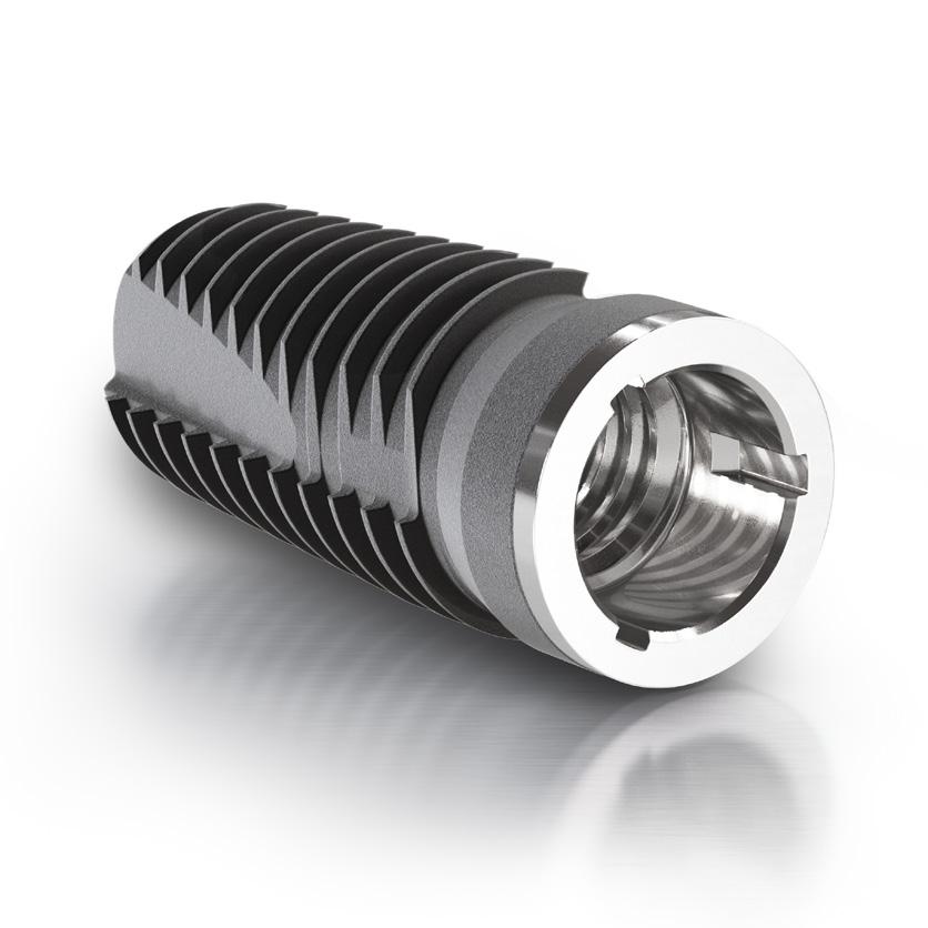
5 CAMLOG SCREW-LINE IMPLANT GENERAL CAMLOG SCREW-LINE implants are endosseous implants available in various lengths and diameters. They are surgically inserted in the bone of the maxilla and/or mandible and serve as an anchor for functional and esthetic oral restorations for partially and fully edentulous patients. The prosthetic restoration is performed with single crowns, bridges or full dentures that are attached to the CAMLOG Implants with the appropriate CAM- LOG Components. CAMLOG SCREW-LINE implants are distinguished by: A slight tapered external geometry, A machined implant neck portion available in two height: 1.4 mm at CAMLOG SCREW-LINE Promote Implant and 0.4 mm at CAMLOG SCREW-LINE Promote plus Implant, Option Platform Switching, Promote Surface, Tube-in-Tube connection with three symmetrically arranged grooves and efficient implant handling with mounted insertion post. The CAMLOG SCREW-LINE implant is not only suitable for late implantations but also for immediate or delayed immediate implantations in maxillary or mandibular bone. The selected healing technique can be either submerged or transgingival. In the case of a one-stage surgical procedure, the implants can be loaded immediately if good primary stability has been achieved and functional loading is appropriate. Abutment guide in the implant Abutment Abutment screw Groove/Cam design Upper inner thread Lower inner thread Implant The implant is easily inserted because the taper of the implant body (3 9 depending on length and diameter) induce self centering. The self-cutting thread provides for continuous grip on the bone and high primary stability. RANGE OF USE FOR CAMLOG SCREW LINE IMPLANT A deeper coronal implant shoulder is especially beneficial in treating esthetically challenging areas. The machined segment of a CAMLOG SCREW- LINE Implant Promote plus surface measures only 0.4 mm. The implant can therefore be inserted into the bone as far as this segment *. The following clinical prerequisites should be present: Normal to thick biotype Gingival height of at least 3.0 mm Minimum width of 1.0 mm of the attached gingiva Minimum distance of 2.0 mm between attached gingiva and mimetic musculature. 1.4 mm Machined implant shoulder surface Machined implant neck portion Abrasive-blasted, acidetched Promote - Surface (micro-macrosurface) 0.4 mm * Schwarz F, Alcoforado G, Nelson K, Schaer A, Taylor T, Beuer F, Strietzel FP. Impact of implant abutment connection, positioning of the machined collar/microgap, and platform switching on crestal bone level changes. Camlog Foundation Consensus Report. Clin.Oral Impl. Res. 2014;25(11): CAMLOG SCREW-LINE Promote Implant CAMLOG SCREW-LINE Promote plus Implant 3


6 CAMLOG SCREW-LINE IMPLANT MATERIALS All CAMLOG SCREW-LINE implants are made of titanium grade 4. The CAMLOG Abutments and abutment screws are made of titanium alloy Ti6Al4V ELI. PRODUCT PRECISION For the most part, the inner and outer geometry of the CAMLOG Implants and abutments are rotary machined. As a result, the tolerances can be kept very small as well as excellent component precision without impacting the material structure. The CAMLOG Implant abutment connection ensures a very precise, stable and rotation-resistant connection to the CAMLOG Prosthetic components. Lower inner thread Upper inner thread Tube-in-Tube Connection INNER CONFIGURATION OF THE IMPLANT The CAMLOG Tube-in-Tube Connection is a 5.4 mm deep implant-abutment connection with antirotational locking mechanism. The three symmetrically arranged grooves are located in the 1.9 mm deep cylindrical drill hole in the coronal region. This region leads apically to an upper thread. This is followed by a thinner and longish cylindrical threaded bore. The abutment screw of the two-piece abutment engages in this lower inner thread. The CAMLOG Tube-in-Tube Connection had undergone extensive scientific studies and achieved above average good results for tightness and precision fit. Implants with Ø 3.3 mm dispose only the Lower inner thread. For optimal positioning of the abutments in the implant, they should be aligned in the bone so that one of the three grooves points vestibularly. The drivers and insertion post include markings on the outside that correspond to the three grooves of the implant inner configuration. Groove/cam design of CAMLOG Implant abutment connection 4
7 IMPLANT DIMENSIONS Article Art.-No. L A L L A A 1.4 mm 0.4 mm CAMLOG SCREW-LINE Implant, Promote incl. insertion post and cover srew, sterile Material Titanium Grade 4 CAMLOG SCREW-LINE Implant, Promote plus incl. insertion post and cover srew, sterile Material Titanium Grade 4 K * 11 mm K * 3.3 mm 13 mm K * 16 mm K mm K mm 3.8 mm K mm K mm K mm K mm 11 mm K mm K mm K mm K mm 5.0 mm K mm K mm K mm K mm 6.0 mm K mm K mm K * 11 mm K * 3.3 mm 13 mm K * 16 mm K mm K mm 3.8 mm K mm K mm K mm K mm 11 mm K mm K mm K mm K mm 5.0 mm K mm K mm K mm K mm 6.0 mm K mm K mm 2.7 mm 3.5 mm 3.9 mm 4.6 mm 5.5 mm 2.7 mm 3.5 mm 3.9 mm 4.6 mm 5.5 mm Note: The implant length (L) is the distance from the apical curve to the machined shoulder surface of the implant. A Ø: Apical diameter (mean value) * IMPORTANT NOTE CAMLOG Implants with a diameter of Ø 3.3 mm. These are an alternative in cases where the alveolar ridge width is only 5 6 mm. Because of their lower mechanical strength compared with larger diameter implants, they should only be used under the following conditions: As single implants, they should be used only to replace mandibular incisors and/or maxillary lateral incisors. Edentulous mandibles can be prosthetically restored with a barsplinted restoration consisting of at least four implants Ø 3.3 mm without distal extensions. Implants of Ø 3.3 mm are suitable for a partially edentulous arch when combined with implants of larger diameter for splinted superstructures. However, the limited strength of the implants with Ø 3.3 mm must be taken into account. Avoid excessive mechanical stressing of the implants when using ball abutments in combination with Ø 3.3 mm implants. The healing time for Ø 3.3 mm implants is at least 12 weeks. Double crown constructions are not allowed on Ø 3.3 mm implants. 5


8 CAMLOG SCREW-LINE IMPLANT OPTION PLATFORM SWITCHING CAMLOG SCREW-LINE implants allow the option Platform Switching (PS). The platform switching option must only be used with the CAMLOG SCREW-LINE implants with K article numbers and prosthetics components PS with K article numbers. Appropriate healing caps, impression posts and abutments are available and are marked with PS: CAMLOG HEALING CAPS PS CAMLOG Healing caps PS (cylindrical, wide body, bottleneck) are tapered in diameter in the area of the implant shoulder and thus enable the soft tissue to adapt over the implant shoulder. IMPORTANT NOTE If CAMLOG Healing caps PS are used for healing, the later prosthetic restoration, incl. the impression, must use CAMLOG Prosthetics components PS for platform switching to prevent tissue injury. cylindrical wide body bottleneck CAMLOG IMPRESSION POSTS PS Use of the CAMLOG Healing caps PS requires application of the geometrically adapted CAMLOG Impression posts PS for platform switching due to soft tissue adaptation over the implant shoulder. Impression post PS open tray Impression post PS closed tray CAMLOG ABUTMENTS PS CAMLOG Abutments PS are also tapered in the area of the shoulder support making it possible to adapt soft tissue over the implant shoulder for the prosthetic restoration. Temporary Abutment PS Estomic Abutments PS Universal Abutment PS 6

.")
9 IMPLANT POSITION PLANNING The planning of implant-prosthetic reconstruction requires a team approach and a high level of attention to detail and clinical experience of all concerned. This is equally true for the restorative dentist, the surgeon, the dental technician,and the dental office support staff such as the nurse, hygienist and chair side assistant. The following aspects should be taken into account during planning: CL (Crown Length) LEVERAGE RATION ON IMPLANT The loading of the implant-bone interface is determined by the leverage ratio from the osseointegration-related resistance to the prosthetic load arm (equal to the supracrestal implant length plus crown length from the implant shoulder). If the implant length (IL) is less than the length of the crown (CL), measures must be taken to reduce loading (e.g. using prosthetic splints). The ratio of crown length (CL) to implant length (IL) should be 0.8:1 maximum. IL (Implant Length) RESTORATIONS FIXED RESTORATION Single Crowns Single-crown treatment is a possible form of treatment under the aspect of a Restitutio ad integrum. It contains all the beneficial elements of periodontal prosthetic rehabilitation: Physiologically adequate biomechanical loading prevents further atrophy of the hard- and soft tissue Good preconditions for natural-looking esthetics are established Oral hygiene is simple Fabrication is technically straightforward Readily extendable/alterable. 2-3 mm implant shoulder up to the cemento-enameljunction mm 5 mm bone level up to the approximal contact point mm 3-4 mm implant shoulder up to the gingival margin 7


10 IMPLANT POSITION PLANNING Esthetically challenging region To achieve an esthetically successful estoration, a number of important elements are required: a harmonious gingiva line, optimal implant positioning as well as vertical/orofacial and mesio-distal dimensions, a physiological crown shape, and the presence of interdental papillae. The indications for the hard-tissue configurations to be preserved and for soft-tissue management must be observed during planning mm mm Ø x Ø x > 3 mm Ø x mm Implant diameters and lengths must be sized properly to leave adequate bone (at least 1 mm) around the implant. Maintain a minimum distance of 1.5 mm to an adjacent natural tooth and 3 mm to an adjacent implant. Structure-preserving or structure-sparing procedures must be used during flap creation and implant placement. In addition, oral hygiene requirements must be kept in mind during planning. Mesio-distal implant position at bone level Distances at bone level Splinted crowns In the event of unfavorable leverage relations around the implant, a choice must be made between a longer implant or, if this is anatomically impossible, splinting adjacent crowns. If splinting is required by reason of stability, then hygienic requirements must also be taken into account. Development of a uniform insertion direction for the crown block must be part of the abutment preparation. The implant-to-abutment connection should not be altered. Single-crown restoration Crown-splinting 8

 or primary (bar-) splinted structure on implants is called passive fit.")

11 Implant-supported bridges CAMLOG SCREW-LINE implants are as well dedicated for Implant-supported bridges. Implant distribution should be structured in such a way that spanned segments are kept small. Development of a uniform insertion direction for the crown block should be part of the abutment preparation. The implant-to-abutment connection should not be altered. Cement-retained bridge REMOVABLE RESTORATIONS A hybrid denture may be implant-retained and mucosa-supported, or simply implant-supported. The tension-free seat of a secondary (telescopic crown) or primary (bar-) splinted structure on implants is called passive fit. In the case of telescopic crowns, this is obtained through intraoral bonding of the secondary crowns (preferably galvano crowns) onto the tertiary framework. In the case of bar structures, it involves the use of bar sleeves for a passive fit and intraoral bonding of the titanium bonding base. The idea is to create a fit that is free from stress or to minimize stress on the implants. When planning a removable denture, the implants should be placed so that, if necessary, extending to a fixed restoration is possible. Double crowns The production precision of the CAMLOG Connection is particularly necessary with a telescopic crown restoration since the abutments can be fastened always in the same, exactly defined position on the implant. A precision fit for the removable superstructure is made simple and consistent in every case. Tension-free seat through intraoral bonding of the secondary crowns onto the tertiary framework 9
12 CAMLOG SCREW-LINE IMPLANT IMPLANT POSITION PLANNING Ø 2.5 mm external diameter X-RAY/DRILLING TEMPLATE WITH CT-TUBES FOR CT-PLANNING CT-tubes for the CT-planning are integrated at the appropriate implant positions in the planning templates created from the wax-up/set-up and are used as reference positions in the X-ray image. The CT-tubes have two parts and are made of titanium because this material does not cause any scattering of rays in the CT/DVT. The lower section is polymerized into the template. The upper section is pluggable. The entire CT-tube is used for the radiological diagnostics; the upper section can be removed for surgery. Depending on the software used for the evaluation, titanium CT-tubes or other radio-opaque positioning elements (e.g. steel, barium sulfate) are integrated for the CT/DVT-supported planning. 10 mm Ø 2.1 mm internal diameter 4 mm Example: CT-tubes for CT-planning for pilot drill Ø 2.0 mm Placing the CT-tubes directly on the mucosa makes it possible to determine its density in the CT/DVT. The documentation included with these systems contains more information on this topic. Drill for placement of CT-tubes ORTHOPANTOMOGRAPH r Wimsheim Germany r Basel, Switzerland +E219K K +E219K K +$ KY +$ KX X-Ray planning foils are available in 1.25:1 and 1.4:1 scales for all implant types to check the dimensions on the orthopantomograph. The foil magnifications match the delay factors for most orthopantomographs. However, they should be considered only as approximations in implant dimensioning. K Rev. 2 03/2017 The self-adhesive implant planning films (X-Ray Transfer pictures, scale 1.25:1) for the specific implant type can be attached to the proposed implant positions on the orthopantomograph film. 10
13 FABRICATING THE DRILLING TEMPLATE WITH CT-TUBES FOR CT-PLANNING If a planning or x-ray template with tubes for CT-planning was created, it can be converted into a drilling template after adjusting the tube positions based on the implant planning. If required, the template is reduced to an outline after preparation of the flap to ensure it stays in position during surgery (dental or gingival base outside the surgical area). Pilot drill, without coil, Ø 2.0 mm PILOT DRILLING WITH CT-TUBES FOR CT-PLANNING The pilot drill without coil has a 2.0 mm diameter. It can also be used with the CT-tube for drill Ø 2.0 mm which has a 2.1 mm inner diameter. There are ring markings, whose lower edges define the drill depth of 7 *, 9, 11, 13, 16, 18 and 20 mm. The thickness of each ring mark is 0.4 mm. The 18 and 20 mm markings are not filled in and are used for orientation when using the 4 mm long CT-tube with 2.1 mm internal diameter. 20 mm 18 mm 16 mm 13 mm 11 mm 9 mm 7 mm* CT-tube for CT-planning, inner Ø 2.1 mm IMPORTANT NOTE Only use CT-tubes for drill Ø 2.0 mm with 2.1 mm internal diameter in conjunction with the pilot drill. * The lowest marking corresponds to a drilling depth of 7 mm and is of no significance for the CAMLOG SCREW-LINE implants. 11


14 SURGERY-SET FOR CAMLOG SCREW-LINE IMPLANTS J J J J J J J J J * J * J * J J J J J J J J J J J J J J J or J J J J J J J J J J J J * only for CONELOG SCREW-LINE implants with length of 7 mm ** have to be ordered separately 12


15 J J J ** The same surgery set is used for the CONELOG SCREW-LINE implants as for the CAMLOG SCREW- LINE implants. The drills are arranged and sorted in the set according to the treatment sequence. Color lines indicate the exact drilling sequence. J J J J J J J J J ** J ** J ** J ** J J J J J J J J J J J J ** J ** 13
16 SURGICAL PROCEDURE DRILLING SEQUENCES FOR IMPLANT BED PREPARATION Overview of the implant bed preparation using the example of a CAMLOG SCREW-LINE Promote plus implant with a length of 13 mm. Punch-mark the desired implant position with the Ø 2.3 mm round bur Deep drill along the implant axial line with the Ø 2.0 mm pilot drill Depth control with the Ø /2.0 mm paralleling pin with depth marks Pre-drill with the Ø mm pre-drill Check with the Ø /2.0 mm paralleling pin with depth marks Shape with the form drill Probe the implant bed hole for its bony end Cortical bone drilling 1] Tap SCREW-LINE 2] Ø 3.3 mm Round bur Ø 2.3 mm Pilot drill Ø 2.0 mm 16 mm 13 mm 11 mm 9 mm ** 7 mm rpm Ø 3.8 mm Round bur Ø 2.3 mm Pilot drill Ø 2.0 mm 16 mm 13 mm 11 mm 9 mm ** 7 mm Depth stop Depth stop Paralleling pin Paralleling pin rpm U/min ] Form drills Cortical-Bone (CB) allow speed-reduced implant insertion in cortical bone for bone quality 1*. Ø 4.3 mm Round bur Ø 2.3 mm Pilot drill Ø 2.0 mm 16 mm 13 mm 11 mm 9 mm ** 7 mm Depth stop Paralleling pin 2] We recommend using the tap for bone qualities 1* and 2*. rpm Ø 5.0 mm Round bur Ø 2.3 mm Pilot drill Ø 2.0 mm 16 mm 13 mm 11 mm 9 mm ** 7 mm Depth stop Paralleling pin rpm * Bone quality as documented in Lekholm U, Zarb GA. Patient selection and preparation. In: Branemark PI, Zarb GA, Albrektsson T, editors. Tissue-integrated prostheses-osseointegration in Clinical Dentistry. Chicago: Quintessence Publishing Co; p Ø 6.0 mm Round bur Ø 2.3 mm Pilot drill Ø 2.0 mm 16 mm 13 mm 11 mm 9 mm ** 7 mm Depth stop Paralleling pin ** The lowest marking corresponds to a drilling depth of 7 mm and is of no significance for CAMLOG SCREW-LINE implants. rpm
17 Pre-drill Ø mm 16 mm 13 mm 11 mm 9 mm ** 7 mm Pre-drill Ø mm 16 mm 13 mm 11 mm 9 mm ** 7 mm Depth stop Paralleling pin Form drill Form drill Ø 3.3 mm Ø 3.3 mm Depth stop Paralleling pin Ø 3.8 mm 1] 2] Form drill Cortical-Bone 1] Form drill Cortical-Bone Tab 2] Tab Promote plus Promote plus 0.4 mm 0.4 mm Pre-drill Ø mm 16 mm 13 mm 11 mm 9 mm ** 7 mm Depth stop Paralleling pin Form drill Ø 3.3 mm Ø 3.8 mm Ø 4.3 mm 1] 2] Form drill Cortical-Bone Tab Promote plus 0.4 mm Pre-drill Ø mm 16 mm 13 mm 11 mm 9 mm ** 7 mm Depth stop Paralleling pin Form drill Ø 3.3 mm Ø 3.8 mm Ø 4.3 mm Ø 5.0 mm 1] 2] Form drill Cortical-Bone Tab Promote plus 0.4 mm ] 2] Pre-drill Ø mm 16 mm 13 mm 11 mm 9 mm ** 7 mm Depth stop Paralleling pin Form drill Ø 3.3 mm Ø 3.8 mm Ø 4.3 mm Ø 5.0 mm Ø 6.0 mm Form drill Cortical-Bone Tab Promote plus 0.4 mm
18 SURGICAL PROCEDURE DRILL SPEEDS The drill speed depends on the diameter. The recommended speeds are rpm depending on the drill type (handpiece angle reduction ratio 16:1 20:1). The recommended maximum drilling speed for thread tapping is 15 rpm (handpiece angle reduction ratio 70:1 100:1). The tap adapter for the torque wrench also allows manual tapping. The lower edge of the depth mark is the reference for the preparation depth. COOLING OF DRILLS The cooling occur through external irrigation on the angled hand piece with sterile saline solution (pre-chilled to 5 C/41 F). DRILL LIFE Drill longevity depends on bone quality and drilling technique. The pilot drills, pre-drills, and form drills are good for times. If excessive force has to be applied because of a dull drill, then change the drill immediately to prevent bone overheating. Article Round bur 800 Pilot drill with/without depth stop 2.0 mm 800 Pre-drill mm 600 Form drill with/without depth stop Form drill cortical bone Tap 3.3 mm mm mm mm mm mm mm mm mm mm mm 3.8 mm 4.3 mm 5.0 mm 6.0 mm drilling speed (rpm) max. 15 CAUTION The maximum apical externsion length of the drill is 0.4 mm. 16
19 INCISION LINE The indication used as an example illustrates the insertion of a Ø 4.3/13 mm CAMLOG SCREW-LINE Promote plus implant in the lateral mandible. The implantation technique is two-step transperiosteal. A split flap preparation is selected for the incision line. We recommend this procedure in cases where there is sufficient bone width and no bone augmentation has to be performed. We recommend a split flap preparation only where the thickness of the mucosa is adequate. Otherwise a full mucoperiosteal flap preparation should be performed. After performing a somewhat lingual, paracrestal mucosal incision, a predominantly epiperiosteal flap is created on the vestibular aspect. The muscle is divided and the preparation is continued for approximately another 5 mm. The mucosa is separated 2 3 mm lingually to simplify suturing later. Initial situation After marking the desired implant position (if necessary, with a drilling template), the periosteum is removed circularly only in the area around this site (with gingival punch or scalpel). Depending on the selected implant diameter and implant length, the implant bed is then shaped using the instruments designed for the CAMLOG SCREW-LINE implant. Mucosal incision Epiperiosteal split-flap preparation Removal of the periosteum at the implantation site 17
20 SURGICAL PROCEDURE IMPLANT BED PREPARATION GENERAL DRILL EXTENSION A drill extension is available to prevent resting of the angled handpiece on the remaining dentition during preparation of the implant bed adjacent to elongated teeth. Drill extension DEPTH STOP SCREW-LINE The pilot drill SCREW-LINE and pre-drill have a maximumworking length of 16 mm. The drilling depths of 7*, 9, 11, and 13 mm are lasermarked. Insertable depth stops limit the drilling depths to the selected depths of 9, 11, or 13 mm. Depth stop SCREW-LINE NOTE The depth stops SCREW-LINE are only compatible with the SCREW-LINE pilot and pre-drill. * The lowest marking corresponds to a drilling depth of 7 mm and is of no significance for the CAMLOG SCREW-LINE implants. 18
21 PARALLELING PINS SCREW-LINE WITH DEPTH MARKINGS After each pilot and pre-drilling, the depth and axial directions are checked using the paralleling pins with depth markings. The depth marks and diameter graduations on the paralleling pins allow inspection of the drilling depth and axis at each stage of pilot and predrilling. 16 mm 13 mm 11 mm 9 mm 7 mm* 0 mm PUNCH-MARKING THE CORTICAL BONE The round bur Ø 2.3 mm is used for punch-marking the cortical bone, which simplifies the use of the drills to follow. The bur is inserted up to the bur equator. Recommended drilling speed: 800 rpm Punch-marking the cortical bone * The lowest marking corresponds to a drilling depth of 7 mm and is of no significance for the CAMLOG SCREW-LINE implants. 19


22 SURGICAL PROCEDURE PILOT DRILLING AND DEPTH CONTROL The pilot drill determines the depth and axis of the implant site. The depth marks on the drill correspond to the implant lengths 7 *, 9, 11 and 13 mm. The maximum drilling depth is 16 mm. For safety reasons, a depth stop matching the proposed implant length should be used. Recommended drilling speed: 800 rpm If no drilling template is used, the depth stops may be placed to the pilot drill after the markings have been drilled. Once drilling is complete, the depth and axis of the implant bed is checked using the paralleling pins. If several implants are being placed, a paralleling pin is inserted into the first hole in order to align the other implant axes. 16 mm 13 mm 11 mm 9 mm 7 mm* 0 The pilot drill is aligned parallel to the paralleling pin and visually checked from two planes (sagittal and transversal). Pilot drill, Ø 2.0 mm 800 rpm Paralleling pin SCREW-LINE Pilot drilling Depth control following pilot drilling * The lowest marking corresponds to a drilling depth of 7 mm and is of no significance for the CAMLOG SCREW-LINE implants. 20
23 PRE-DRILLING AND CONTROL AXIS ALIGNMENT A tapered pre-drill SCREW-LINE with a coronal diameter of 2.8 mm and apical diameter of 1.7 mm is available for the SCREW-LINE configuration. 2.0 mm Recommended drilling speed: 600 rpm The depth marks on the drill match the implant lengths 7*, 9, 11 and 13 mm. The maximum drilling depth is 16 mm. For safety reasons, a depth stop matching the proposed implant length should be used. Further drilling is performed with the form drills. 2.8 mm 2.8 mm The axis alignment is controlled with the paralleling pin. 1.7 mm 1.7 mm Pre-drill SCREW-LINE Ø mm, 600 rpm Paralleling pin SCREW-LINE Pre-drilling Control of axis alignment * The lowest marking corresponds to a drilling depth of 7 mm and is of no significance for the CAMLOG SCREW-LINE implants. 21


24 SURGICAL PROCEDURE FORM DRILLING Diameter- and length-specific form drills are available for each implant size. The form drills are color-coded and laser-marked. The form drills included in the surgery sets are supplied with a color-coded, removable depth stop. This must only be used with form drills SCREW-LINE. Length 9 mm 11 mm 13 mm 16 mm Depending on the specified drilling depth (implant length), the hole diameter is expanded progressively with the series of form drills until the intended implant diameter is achieved. The small graduations in diameter achieve a gentle preparation of the bone. Recommended drilling speeds: Ø 3.3 mm 550 U/min Ø 3.8 mm 500 U/min Ø 4.3 mm 400 U/min Ø 5.0 mm 350 U/min Ø 6.0 mm 300 U/min Ø 3.3 mm Ø 3.8 mm Ø 4.3 mm Ø 5.0 mm Ø 6.0 mm Form drill SCREW-LINE Drill sequence in ascending order to the drill hole expansion up to the defined implant diameter. 22


 1.")
.")


.")
25 FORMDRILLING FOR CAMLOG SCREW-LINE Promote plus The CAMLOG SCREW-LINE Promote plus implants are machined over 0.4 mm in the neck section and can accordingly be placed 0.4 mm supracrestally*. If form drilling is performed with a depth stop, the CAMLOG SCREW-LINE Promote plus implant shoulder lies 0.4 mm supracrestal for a planar bone ridge. The reusable depth stops can be used with replacement form drills (delivered without depth stops). 1 mm 1 mm 1 mm 1 mm 0.4 mm 0.4 mm 0.4 mm 0.4 mm 0.4 mm CAMLOG SCREW-LINE Promote plus Implant FORMDRILLING FOR CAMLOG SCREW-LINE Promote A) Placement of the CAMLOG SCREW-LINE Promote Implant: The CAMLOG SCREW-LINE Promote Implants are provided with a 1.4 mm high machined implant neck and can accordingly be placed 1.4 mm supracrestally*. In order to place the CAMLOG Promote Implant 1.4 mm supracrestally - on a planar bone ridge - form drilling is performed to the lower edge of the double line mark. A) 1.4 mm B) Individual form drilling: If a different insertion depth is required, form drilling can be continued deeper in steps of 1 mm (watch for anatomic structures!). In this case, preparation is performed using the laser marks (black). The marks are arranged at intervals of 1.0 mm and are 0.4 mm in width. B) CAMLOG SCREW-LINE Promote Implant CAUTION The maximum apical overlength of the drills is 0.4 mm. The depth stops must be removed before cleaning the drills. The cleaned depth stops must be reattached before sterilization (see Preparation instructions for the CAMLOG /CONELOG Implant System, Art. No. J ). The depth stops can be reordered individually. * Schwarz F, Alcoforado G, Nelson K, Schaer A, Taylor T, Beuer F, Strietzel FP. Impact of implant abutment connection, positioning of the machined collar/microgap, and platform switching on crestal bone level changes. Camlog Foundation Consensus Report. Clin.Oral Impl. Res. 2014;25(11): Form drilling without depth stop Example: insertion depth implant on an irregular bone 23


26 SURGICAL PROCEDURE CHECKING THE IMPLANT BED Probing the implant bed hole for fenestration is recommended. Results of probing tests for the absence of soft tissue in the implant bed hole must be documented in the patient file. Checking the implant bed CORTICAL BONE DRILLING If the bone quality is class 1* the cortical bone drill enables reduced-torqueimplant insertion through controlled circular expansion of the implant bed. The flattened drill tip serves as the depth stop. A color-coded laser-marked cortical bone drill is available for each implant diameter. Recommended drilling speed in rpm: Ø 3.3 mm Ø 3.8 mm Ø 4.3 mm Ø 5.0 mm Ø 6.0 mm Form drill SCREW-LINE Cortical bone * Bone quality as documented in Lekholm U, Zarb GA. Patient selection and preparation. In: Branemark PI, Zarb GA, Albrektsson T, editors. Tissue-integrated prostheses-osseointegration in Clinical Dentistry. Chicago: Quintessence Publishing Co; p Cortical bone drilling Ø 4.3 mm for implant length 13 mm


27 TAPPING All CAMLOG SCREW-LINE implants come with a self-tapping thread. Use of a tap is recommended for bone quality categories 1* and 2*. The maximum speed must not exceed 15 rpm when performing powerassisted tapping. We recommend manual tapping. * Bone quality as documented in Lekholm U, Zarb GA. Patient selection and preparation. In: Branemark PI, Zarb GA, Albrektsson T, editors. Tissue-integrated prostheses-osseointegration in Clinical Dentistry. Chicago: Quintessence Publishing Co; p Ø 3.3 mm Ø 3.8 mm Ø 4.3 mm Ø 5.0 mm Ø 6.0 mm Tap SCREW-LINE, with hexagon, max. 15 rpm Manual tapping is performed with tap adapters for the tap SCREW- LINE and the locked torque wrench. Make sure to pay attention to the axial direction of the implant bed when inserting and removing the tap. The limit for insertion of the tap is the upper edge of the cutting blade. Locked torque wrench Tap adapter, short and long, for tap SCREW-LINE Tapping in the upper region of the implant bed 25

 A + Protected")
 D 1 Quantity index (number of packaging units, 1 digit) Sections of the secondary code Code Explanation (UDI-DI) E / Separator primary/secondary F $$3 Identifier for expiry date G 220427")
28 SURGICAL PROCEDURE IMPLANTATION GENERAL INFORMATION ON PACKAGING AND IMPLANT HANDLING A) Exterior packaging (cardboard) with label: The label on the exterior packaging contains relevant system information and is applied on three sides. This means that the label is clearly readable regardless of stacking of the packages. UDI CODE A B C D E F G H I J K Example product label on the exterior packaging: +E219K / $$ XXXXXXXXXX / 16D Pictogram for CAMLOG Implant Length indication Register with diameter indication in mm and its corresponding color coding UDI-Code according to adjacent table Narrow-side label Backside label Sections of the primary Code Explanation code (UDI-DI) A + Protected HIBC-ID (1 digit) B E219 Manufacturer s code (Altatec) C K Article number (max. 13 digits) D 1 Quantity index (number of packaging units, 1 digit) Sections of the secondary code Code Explanation (UDI-DI) E / Separator primary/secondary F $$3 Identifier for expiry date G Expiry date (6 digits) H XXXXXXXXXX Manufacturer s batch (10 digits) I /16D Identifier for date of manufacture J Date of manufacture (6 digits) K + Variable test mark Further information on the exterior packaging: The bottom side of the CAMLOG Implant packaging refers to the instruction manual in electronic form: In addition, it includes a QR code which links directly to the corresponding webpage. The left side view of the CAMLOG Implant packaging contains the CE label, the corresponding ISO warnings as well as the address of the legal manufacturer. 26


 One side of the implant holder contains information which identifies the type of implant.")
 A scale on the bottom side of the implant holder allows reading the length of the implant: the position of")
 Mounted insertion posts: The")
29 B) Transparent blister with Tyvek foil and primary label: The blister with the Tyvek foil represents the primary packaging, the contents of which are sterile - implant holder with implant and cover screw. Furthermore, the blister includes four self-adhesive patient labels. These can, for example, be used for the patient records, the implant pass, the letter of referral etc. C) Implant holder with implant and cover screw: The implant retention system securely fixates the implant and the cover screw in the packaging. Both the implant and the cover screw can be released and removed via a simple click mechanism with the implant holder. In addition, the implant can be clearly identified in the implant holder after removal from the primary packaging: a) One side of the implant holder contains information which identifies the type of implant. b) The implant diameter can be identified via the color-coding of the insertion post and the cover screw. c) A scale on the bottom side of the implant holder allows reading the length of the implant: the position of the titanium retaining plate on the scale gives the implant length 9, 11, 13 and 16 mm. Information on the type of implant Scale to determine the length of the implant D) Mounted insertion posts: The implants are secured in the implant holder with a color-coded insertion post corresponding to the diameter. The insertion posts are mounted in the implant and can be pulled off easily from the implant after implantation without requiring further tools. Ø 3.3 mm Ø 3.8 mm Ø 4.3 mm Ø 5.0 mm Ø 6.0 mm 27

 for use with the angled hand piece.")

 with insertion")
30 SURGICAL PROCEDURE E) Insertion tools: The implant can be picked up directly with the insertion tool via the mounted insertion post and removed from the implant holder. One of the five illustrated insertion tools can be used for this purpose. The three manual insertion tools for use with the wrench (long, short, extra short). The two insertion tools with ISO shaft (short and long) for use with the angled hand piece. The insertion posts and insertion tools are designed such, that they are also suitable for narrow gaps: none of the components required for inserting the implant have a diameter greater than that of the implant itself. Furthermore, the long insertion tools also allow the placement of implants in narrow and deep anatomical situations. Insertion tool with ISO shaft The figure illustrates the use of a handpiece insertion tool (with ISO shaft) with insertion post for the CAMLOG Implant Ø 3.3 mm under tight interdental conditions. Groove markings on the insertion tool Insertion post 28


31 OPENING OF THE PACKAGING AND TRANSFER OF THE IMPLANT HOLDER TO THE STERILE ZONE The exterior packaging is opened with the perforated packaging tab. NOTE If the perforated packaging tab is partially or fully open, the packaging is deemed damaged and the implant may no longer be used. The four self-adhesive patient labels included with the blister, are intended for documentation purposes for example: Implant pass Letter of referral Patient records The blister with the Tyvek foil forms the sterile barrier. As long as the blister as well as the Tyvek foil are undamaged, sterility of the content is assured. Opening of the blister: At the two sharp angle corners, the blister is fitted with tabs which allow easy separation of the Tyvek foil from the blister. 29
: A: DISCARDING THE IMPLANT HOLDER ONTO THE STERILE")


32 SURGICAL PROCEDURE There are two ways to transfer the implant holder to the sterile zone (A and B): A: DISCARDING THE IMPLANT HOLDER ONTO THE STERILE SHELF The opened blister is gently compressed between two fingers in the marked position. The blister is designed such, that the implant holder is retained in the blister as long as finger pressure is maintained. This allows controlled placement over the sterile shelf. By releasing finger pressure, the holder can be discarded onto the sterile shelf in a controlled manner. B: PASSING THE IMPLANT HOLDER TO THE IMPLANTOLOGIST The opened blister is passed to the implantologist. The implantologist takes the implant holder with two fingers at the intended place. Then the implant holder can be used in the sterile zone. 30


 and press together to release the lock on the")
33 PICKING UP THE INSERTION POST WITH THE MANUAL INSERTION TOOL The front part of the implant holder is held between two fingers and the insertion tool is mounted into the insertion post by applying pressure. This ensures a secure seat of the insertion tool in the insertion post. Contamination from non-sterile instruments must be avoided. NOTE It should be noted that picking up the insertion post with the insertion tool is done by applying slight pressure. This ensures secure retention of the insertion post in the insertion tool. The three groove markings on the head of the insertion post serve easy picking up of the post with the insertion tool, which is also fitted with the corresponding three markings. Observe the correct alignment during the pick-up process! Furthermore, the three groove markings on the insertion tool and on the insertion post relate to the groove position of the implant-abutment connection. The further steps for removing the implant are as follows: Hold the implant holder at the rear section (see arrows in illustration) and press together to release the lock on the implant holder and thus release the implant; Loosen the insertion post with a slight twist (approx. 30 clockwise with the insertion tool); Lift out insertion post in upward direction (do not tilt)


34 SURGICAL PROCEDURE PICKING UP THE INSERTION POST WITH THE ANGLED HAND PIECE Optionally, the insertion post can also be picked up directly with the ISO shaft handpiece insertion tool on an angled hand piece. The front part of the implant holder is held and then the insertion post is picked up with the handpiece insertion tool by applying pressure. During the pick-up process, observe the correct alignment of the 3 groove markings on the head of the insertion post and the insertion tool. Contamination from non-sterile instruments must be avoided. Observe the correct alignment during the pick-up process! NOTE It should be noted that picking up the insertion post with the insertion tool is done by applying slight pressure. This ensures secure retention of the insertion post in the insertion tool. The further steps for removing the implant are as follows: Hold the implant holder at the rear section (see arrows in illustration) and press together to release the lock on the implant holder and thus release the implant; Remove the insertion post from the holder with a slight twist (approx. 30 clockwise with the insertion tool); Lift out the insertion post by pulling the angled hand piece upwards (do not tilt)
35 IMPLANT INSERTION AND POSITIONING Using the insertion tool, the implant is inserted into the implant bed and carefully screwed in clockwise either manually or with the angled hand piece (maximum speed may not exceed 15 rpm). Pay attention to the axial alignment of the implant bed. In the case of manual insertion, once the implant has been inserted into the implant bed, the implant can be screwed into its final position with the wrench. If the thread was tapped in advance, the positions of the threaded ends in the cortical bone and on the implant must match. It is recommended to first rotate the insertion tool with the implant carefully to the left manually, until the thread socket can be felt. Then the implant is screwed in clockwise manually with the insertion tool. When reaching the planned insertion depth (see section on form drilling), one of the 3 grooves should face in a vestibular direction. Insertion of implant with a manual insertion tool Insertion of implant with a machine insertion tool If it was decided to set preparation depths for the implants individually by removing the depth stop during form drilling, this must be kept in mind when inserting the implant. It is possible to individually position implants vertically to match the drilling depth. Screw insertion of implant with manual insertion tool and wrench (max. 15 rpm) Screw insertion of implant with a machine insertion tool and angled hand piece (max. 15 rpm) Manually screwed in implant Machine screwed in implant 33
36 SURGICAL PROCEDURE The following is to be observed during implantation: Groove markings are applied to the insertion tool and the insertion post which correspond to the three grooves of the implant-abutment connection. These permit a check of the groove positions during the insertion and their orientation as required for the prosthesis. Manual insertion tool for wrench Machine insertion tool with ISO shaft If the dental technician has not indicated the groove position, a vestibular orientation is advantageous in most cases since the angle of angulated abutments originates at a groove. NOTE Keep in mind during positioning of the grooves that turning to the next groove position (120 ) will cause the screw implant to be inserted about 0.2 mm deeper. CAMLOG Insertion post Groove; Vestibular oriented CAMLOG SCREW-LINE implant After successful checking of the implantation depth (see section Form drilling ) as well as the position of the grooves (see above), the insertion post can be pulled from the implant using the torque wrench or with the angled hand piece. Attention should be paid to sufficient primary stability of the implant. Prior to removal, ensure sufficient mating between the insertion tool and the insertion post with slight axial pressure on the insertion tool. If the primary stability is low after placing the implant, the implant can be stabilized downwards with a probe or forceps during extraction of the insertion post. Removal of the insertion post for manual screwing in Removal of the insertion post for machine screwing in 34


37 ADDITIONAL INSTRUMENTS PRE-DEFINED BREAKING POINT OF THE INSERTION POST To protect the inner configuration of the implant, the insertion posts are fitted with a pre-defined breaking point. If the torque is too high during insertion of the implant, the insertion post snaps off at the pre-defined breaking point. This ensures that the inner configuration of the implant is not damaged and that the fracture fragment of the post can be removed with forceps as a single piece from the implant. pre-defined breaking point The fractured piece must be secured with a ligature prior to removal to avoid aspiration. If the snapping at the predetermined breaking point occurs at the same time as final positioning of the implant, the fragment of the insertion post is extracted as described above, and the procedure can be continued as planned. The cover screw or a healing cap is applied to the implant or it is already fitted with a prosthetic component. REMOVAL ADAPTER FOR IMPLANTS If the implant is not in the final position when the insertion post snaps at the pre-defined breaking point, the implant must be removed as described in the following, and the reason for snapping investigated. In order to remove the implant after snapping of the insertion post at the pre-defined breaking point, CAMLOG Removal adapters are available for all CAMLOG SCREW-LINE implants. In order to remove the implant, the manual insertion tool is mounted to the removal adapter. Here it should be noted that picking up the removal adapter with the insertion tool is done by applying slight pressure. CAMLOG Removal adapters for all diameters Three lateral markings correspond with the cams of the removal adapter and thus allow easy insertion of the removal adapter into the implant, until the cams fit the grooves. NOTE The CAMLOG Removal adapter should only be used for the explantation not osseointegrated implants. The CAMLOG Removal adapter should not be used to change implant axis or to adjust the height of the implant. Otherwise the inner configuration of the implant can be damaged. 35

")
 the implant holder (see illustration) the cover screw can be released. The screw is freely accessible after this procedure.")
38 SURGICAL PROCEDURE Afterwards the implant can be unscrewed with the mounted removal adapter using the insertion tool and the locked torque wrench or the angled hand piece. The implant must be disposed. Insertion of the removal adapter to the implant Unscrewing the implant using the removal adapter, the insertion tool as well as the locked torque wrenche SUBMERGED HEALING The cover screw for submerged healing is located in the middle section of the implant holder and protected against falling out (red circle) in a provided well (Ø 3.3 mm, Ø 3.8 mm, Ø 4.3 mm, Ø 5.0 mm and Ø 6.0 mm). By closing (compressing) the implant holder (see illustration) the cover screw can be released. The screw is freely accessible after this procedure. This procedure is only possible if the insertion post and implant are no longer in place. Using a screwdriver, the cover screw can be picked up directly from the implant holder by applying slight pressure. 36

.")


39 Pick up the cover screw with the screwdriver, hex, and insert it into the CAMLOG SCREW-LINE implant manually controlled (danger of aspiration!). The cover screw must only be tightened manually controlled using the hex screwdriver. Inserting the CAMLOG Cover screw CAMLOG SCREW-LINE implant with CAMLOG Cover screw Wound closure 37


40 SURGICAL PROCEDURE TRANSGINGIVAL HEALING CAMLOG HEALING CAPS Use of the CAMLOG Healing caps supports the development of the periimplant soft tissue. CAMLOG Healing caps are available in three different geometries: cylindric wide body bottleneck The healing caps are color-coded to match the respective implant diameter. CAMLOG Healing caps are inserted into the CAMLOG SCREW-LINE implant and tightened manually using a screwdriver, hex. The healing cap rests on the machined implant shoulder and does fully cover it. Connection CAMLOG SCREW-LINE implant CAMLOG Healing cap CAMLOG HEALING CAPS PS FOR PLATFORM SWITCHING The CAMLOG Healing caps PS (cylindrical, wide body, bottleneck) are tapered in diameter on the apical end and enable the adaptation of soft tissue over the implant shoulder. IMPORTANT NOTE! If CAMLOG Healing caps PS are used for healing, the later prosthetic restoration, including the CAMLOG Impression taking, must use CAMLOG Prosthetic components PS for platform switching to prevent tissue injury! Connection CAMLOG SCREW-LINE implant CAMLOG Healing cap PS 38
41 Article Art.-No. GH G GH GH G G CAMLOG Healing cap, cylindrical CAMLOG Healing cap, wide body J mm 3.3 mm 3.3 mm J mm 3.3 mm J mm 3.8 mm J mm 4.0 mm 3.8 mm J * 6.0 mm 3.8 mm J mm 4.3 mm J mm 4.0 mm 4.3 mm J * 6.0 mm 4.3 mm J mm 5.0 mm J mm 4.0 mm 5.0 mm J * 6.0 mm 5.0 mm J mm 6.0 mm J mm 4.0 mm 6.0 mm J * 6.0 mm 6.0 mm J mm 4.5 mm 3.3 mm J mm 4.5 mm J mm 4.9 mm J mm 4.0 mm 5.0 mm J mm 5.0 mm J mm 5.4 mm J mm 4.0 mm 5.5 mm J mm 5.5 mm J mm 6.1 mm J mm 4.0 mm 6.2 mm J mm 6.2 mm J mm 7.1 mm J mm 4.0 mm 7.2 mm J mm 7.2 mm J mm 4.0 mm 3.5 mm GH G CAMLOG Healing cap, bottleneck J mm 4.0 mm 3.8 mm J mm 4.0 mm J mm 4.5 mm 4.3 mm J mm 4.5 mm J mm 5.2 mm 5.0 mm J mm 5.2 mm J mm 6.2 mm 6.0 mm J mm 6.2 mm GH: Gingival height GØ: Gingival diameter * suitable for bite registration 39
42 Article Art.-No. GH G PS PS GH GH G G CAMLOG Healing cap PS, cylindrical CAMLOG Healing cap PS, wide body K mm 3.3 mm K mm 4.0 mm 3.3 mm K * 6.0 mm 3.3 mm K mm 3.8 mm K mm 4.0 mm 3.8 mm K * 6.0 mm 3.8 mm K mm 4.4 mm K mm 4.0 mm 4.4 mm K * 6.0 mm 4.4 mm K mm 5.1 mm K mm 4.0 mm 5.1 mm K * 6.0 mm 5.1 mm K mm 5.0 mm 3.8 mm K mm 5.0 mm K mm 5.5 mm 4.3 mm K mm 5.5 mm K mm 6.2 mm 5.0 mm K mm 6.2 mm K mm 7.2 mm 6.0 mm K mm 7.2 mm PS G K mm 4.0 mm 3.8 mm K mm 4.0 mm GH CAMLOG Healing cap PS, bottleneck K mm 4.5 mm 4.3 mm K mm 4.5 mm K mm 5.2 mm 5.0 mm K mm 5.2 mm GH: Gingival height GØ: Gingival diameter * suitable for bite registration 40

43 CAMLOG HEALING CAPS, CYLINDRICAL, AND WIDE BODY The cylindrical and wide body CAMLOG Healing caps are for standard use. After removal of the CAMLOG Cover screw, diameter-matching CAMLOG Healing caps are screwed in manually with a screwdriver, hex. A gingival height ensuring that the healing cap sits mm supragingivally should be selected. The CAMLOG Impression is taken once the peri-implant soft tissue has been stabilized. CAMLOG Healing cap, cylindrical CAMLOG Healing cap, wide body CAMLOG HEALING CAPS PS, CYLINDRICAL, AND WIDE BODY CAMLOG SCREW -LINE Implants with Promote plus surface are suitable for the platform switching option. Because the surface is brought further upward, more bone is available close to the implant shoulder. Because the surface is brought further upward, more bone is available in coronal direction. The shift in the horizontal shoulder towards the implant axis at the implant shoulder level ensures more space for soft-tissue management. CAMLOG Healing cap PS, cylindrical, Height 2.0 mm, for submerged healing CAMLOG Healing cap PS, cylindrical, Height 4.0 mm, for submerged healing CAMLOG Healing cap PS, wide body 41
IMPRESSION-TAKING, BITE REGISTRATION, AND TEMPORARY RESTORATION ON CAMLOG IMPLANTS. a perfect fit
 a perfect fit IMPRESSION-TAKING, BITE REGISTRATION, AND TEMPORARY RESTORATION ON CAMLOG IMPLANTS Open and closed impression-taking Impression-taking for option platform switching Bite registration Temporary
Cost-effective immediate restoration in the anterior region of the mandible (isy by CAMLOG)
") Cost-effective immediate restoration in the anterior region of the mandible (isy by CAMLOG) Many patients wish to have permanent dentures, and often this wish can be fulfilled by one of the greatest developments
Cost-effective immediate restoration in the anterior region of the mandible (isy by CAMLOG) Many patients wish to have permanent dentures, and often this wish can be fulfilled by one of the greatest developments
Locator retained mandibular complete prosthesis (isy Implant System)
") Locator retained mandibular complete prosthesis (isy Implant System) Mucosa-supported complete prostheses with poor fit greatly reduce people's quality of life. This is why the importance of implant-supported
Locator retained mandibular complete prosthesis (isy Implant System) Mucosa-supported complete prostheses with poor fit greatly reduce people's quality of life. This is why the importance of implant-supported
4766 Research Dr. San Antonio, TX insightdentalsystems.com
 OVERVIEW OF THE INSIGHT DENTAL IMPLANT DELIVERY SYSTEM The IDS system comes in a unit dose implant system where its advantage provides sterile instrumentation in one single-use kit. It is organized to
CAMLOG IMPLANT SYSTEM PRODUCT CATALOG
 a perfect fit CAMLOG IMPLANT SYSTEM PRODUCT CATALOG Valid from Janua y 2014 A partnership with CAMLOG encompasses the exceptional price-performance ratio of the CAMLOG Products and a custom-built service
a perfect fit CAMLOG IMPLANT SYSTEM PRODUCT CATALOG CAMLOG IMPLANT SYSTEM PRODUCT CATALOG SEPTEMBER 2014
 a perfect fit CAMLOG IMPLANT SYSTEM PRODUCT CATALOG SEPTEMBER 2014 CAMLOG IMPLANT SYSTEM PRODUCT CATALOG Valid from September 2014 A partnership with CAMLOG encompasses the exceptional price-performance
CAMLOG. IMpLAnt SYSTEM INTERNATIONAL. Valid from March 2011
 CAMLOG IMpLAnt SYSTEM 1 Product CatALOG 2011 INTERNATIONAL Valid from March 2011 ADDED VALUE A partnership with CAMLOG encompasses the exceptional price-performance ratio of the CAMLOG Implant System and
a perfect fit CAMLOG GUIDE SYSTEM Planning, template fabrication and implantation
 a perfect fit CAMLOG GUIDE SYSTEM Planning, template fabrication and implantation TABLE OF CONTENTS GENERAL SYSTEM INFORMATION ON THE CAMLOG IMPLANT SYSTEM CAMLOG GUIDE SYSTEM PRODUCT DESCRIPTION HEALING
Multi-Unit Abutment System SIC Safe on Four. Optimum use of available bone by angled placement of implants
 Multi-Unit Abutment System SIC Safe on Four Optimum use of available bone by angled placement of implants Multi-Unit Abutment System SIC Safe on Four Safe on Four The SIC Safe on Four system is a further
TITANIUM BASES CAD/CAM FOR CROWN AND BRIDGE RESTORATIONS CAD/CAM PROSTHETICS ON CAMLOG AND CONELOG IMPLANTS
 TITANIUM BASES CAD/CAM FOR CROWN AND BRIDGE RESTORATIONS CAD/CAM PROSTHETICS ON CAMLOG AND CONELOG IMPLANTS TABLE OF CONTENTS GENERAL SYSTEM INFORMATION 2 CAMLOG AND CONELOG TITANIUM BASES CAD/CAM PRODUCT
PRODUCT CATALOG 2014 CONELOG IMPLANTATSYSTEM PRODUCT PRODUKTKATALOG CATALOG 2014
 PRODUCT CATALOG 2014 CONELOG IMPLANTATSYSTEM PRODUCT PRODUKTKATALOG CATALOG 2014 Valid from May 2014 ADDED VALUE THROUGH COMPETENCE IN IMPLANTOLOGY A partnership with CAMLOG encompasses the exceptional
The intelligent system.
 The intelligent system. Contents This is isy The intelligent system 5 Cost efficient implant sets 7 Total flexibility 9 Purposeful simplicity 11 The digital future 13 Quality without compromise 15 isy
isy indications and techniques
 This is isy 3 The isy Implant System demonstrates its unique talents in numerous indications. Its intelligence allows the clinician to focus on what is most common in their everyday implant practice. isy
GMI FRONTIER implant system. Surgical procedures guide
 GMI implant system Surgical procedures guide ABOUT THIS MANUAL This surgical procedures guide or surgical manual for the GMI implant system is designed solely to provide instructions for using GMI products,
Astra Tech Implant System. Manual and product catalog. Guided surgery. Computer guided implant treatment with the Astra Tech Implant System EV
 Astra Tech Implant System Manual and product catalog Guided surgery Computer guided implant treatment with the Astra Tech Implant System EV Simplicity without compromise The design philosophy of the Astra
Guided surgery manual
 Including product catalog Guided surgery manual SIMPLANT computer guided implant treatment with the ASTRA TECH Implant System EV CONTENTS Introduction Drilling protocol and bone classification 4 Implant
OCCLUSALLY SCREW-RETAINED
 a a perfect fit fit OCCLUSALLY SCREW-RETAINED RESTORATIONS WITH VARIO SR PROSTHETIC COMPONENTS ON CAMLOG VARIO SR ABUTMENTS Basic Information Aligning tool for controlling the implant axes Impression taking
GMI. MONOLITH implant system. Surgical procedures guide
 GMI MONOLITH implant system Surgical procedures guide ABOUT THIS MANUAL This surgical procedures guide or surgical manual for the GMI MONOLITH implant system is designed solely to provide instructions
INSTRUCTIONS FOR THE DENTIST. synocta impression procedure, Screw-retained and Snap-on. Screw-retained (Open tray) Snap-on (Closed tray)
 Snap-on (Closed tray)") INSTRUCTIONS FOR THE DENTIST synocta impression procedure, Screw-retained and Snap-on Screw-retained (Open tray) Snap-on (Closed tray) click 1. Attach synocta Impression caps to implants. Hand-tighten
INSTRUCTIONS FOR THE DENTIST synocta impression procedure, Screw-retained and Snap-on Screw-retained (Open tray) Snap-on (Closed tray) click 1. Attach synocta Impression caps to implants. Hand-tighten
Osseointegrated dental implant treatment generally
 Placement of Dental Implants Without Flap Surgery: A Clinical Report Bader H. Al-Ansari, BDS, MScD*/Robert R. Morris, DMD** Traditionally, the procedure of implant placement requires a surgical periosteal
Basic Information on Straumann Guided Surgery. Straumann Dental Implant System
 Basic Information on Straumann Guided Surgery Straumann Dental Implant System The ITI (International Team for Implantology) is academic partner of Institut Straumann in the areas of research and education.
NARROW DIAMETER implant
 ND NARROW DIAMETER implant TABLE OF CONTENTS ND - NARROW DIAMETER implant Implant characteristics page 04 Dental implant page 05 Open Tray Impression Transfer page 06 Titanium Abutments page 07 O-Ball
» Guided Surgery. by MEDENTiKA « MEDENTIGUIDE SURGERY MANUAL MICROCONE. IPS Implant systems
 » Guided Surgery by MEDENTiKA «IPS Implant systems MEDENTIGUIDE MICROCONE SURGERY MANUAL » MedentiGuide «MedentiGuide drill sleeves support the surgeon in preparing the implant bed for MEDENTiKA implants.
Replacement of a missing posterior tooth in the mandible (isy by CAMLOG)
") Replacement of a missing posterior tooth in the mandible (isy by CAMLOG) Implants are generally regarded as being a high-end therapy involving relatively high costs. In the quest for economical treatment
Replacement of a missing posterior tooth in the mandible (isy by CAMLOG) Implants are generally regarded as being a high-end therapy involving relatively high costs. In the quest for economical treatment
NEODENT GUIDED SURGERY
 NEODENT GUIDED SURGERY MANUAL Grand Morse Connection Helix Implant GRAND POSSIBILITIES WITH A LIMITLESS SOLUTION. GRAND MORSE NEODENT GUIDED SURGERY. 4 5 6 CONTENTS 1. CLINICAL STEP BY STEP OF GRAND
» Guided Surgery. by MEDENTiKA « MEDENTIGUIDE SURGERY MANUAL QUATTROCONE QUATTROCONE30. IPS Implant systems
 » Guided Surgery by MEDENTiKA «IPS Implant systems MEDENTIGUIDE QUATTROCONE QUATTROCONE30 SURGERY MANUAL » MedentiGuide «MedentiGuide drill sleeves support the surgeon in preparing the implant bed for
Trefoil Procedure manual
 Trefoil Procedure manual This procedure manual does not replace attending a complete training program Note: In order to improve readability, Nobel Biocare does not use or in the running text. By doing
a perfect fit SURGERY CAMLOG /CONELOG SCREW-LINE Surgery set and drills Osteotomy sets ALTApin set Sinus set Complementary surgical instruments
 a perfect fit SURGERY CAMLOG /CONELOG SCREW-LINE Surgery set and drills Osteotomy sets ALTApin set Sinus set Complementary surgical instruments SURGERY SET CAMLOG /CONELOG SCREW-LINE THE SURGERY SET AND
Guidance for. implant removal. Straumann Dental Implant System
 Guidance for implant removal Straumann Dental Implant System The ITI (International Team for Implantology) is academic partner of Institut Straumann AG in the areas of research and education. CONTENTS
Very small abutment head easy and secure handling. Ankylos. The SmartFix concept. Prosthetic solution on angled implants
 Very small abutment head easy and secure handling Ankylos The SmartFix concept Prosthetic solution on angled implants Stable prosthetic fit The area supporting the prosthesis is extended distally by the
SURGICAL PROCEDURES FOR ROXOLID IMPLANTS
 SURGICAL PROCEDURES FOR ROXOLID IMPLANTS 1 ABOUT THIS BROCHURE The brochure Surgical Procedures for Roxolid Implants provides dental practitioners and related specialists with information about the implant
Anchorage system. tomas / Sets Page 270 tomas / Pins Page 271 Instruments and accessories Page 273 Patient consultation material Page 282
 tomas / Sets Page 270 tomas / Pins Page 271 Instruments and accessories Page 273 Patient consultation material Page 282 266 . innovative comprehensive efficient. Dentaurum Online Shop shop.dentaurum.com
The Uniti implant system is designed to be simple to learn and use. A seamless surgical protocol renders the system user friendly.
 Surgical Manual The Uniti implant system is designed to be simple to learn and use. A seamless surgical protocol renders the system user friendly. For the experienced practitioner it will take no more
Innovative Präzision Made in Germany
 E OT-F 2 Surgical Manual Introduction The OT-F 2 implants are self-tapping cylindrical screw implants made of titanium grade 4 for insertion down to the bone crest level. The surgical protocol is usually
Smarter Thinking. Simpler Design. Prima Plus. Surgical Manual
 Smarter Thinking. Simpler Design. Prima Plus Surgical Manual TABLE OF CONTENTS PRIMA PLUS IMPLANT SURGICAL MANUAL SURGERY Prima Plus Characteristics 4 Surgical Considerations 5 Prima Plus Surgical Sequence
Case Study. Case # 1 Author: Dr. Suheil Boutros (USA) 2013 Zimmer Dental, Inc. All rights reserved. 6557, Rev. 03/13.
 2013 Zimmer Dental, Inc. All rights reserved. 6557, Rev. 03/13.") Placement of a Zimmer Trabecular Metal Dental Implant with Simultaneous Ridge Augmentation and Immediate Non-Functional Loading Following Tooth Extraction and Orthodontic Treatment for Implant Site Development
Placement of a Zimmer Trabecular Metal Dental Implant with Simultaneous Ridge Augmentation and Immediate Non-Functional Loading Following Tooth Extraction and Orthodontic Treatment for Implant Site Development
NARROW DIAMETER implant
 N NARROW IAMETER implant N Precision dental solutions C-Tech Implant is a dynamic company with aggressive growth, producing components and product lines primarily for dental implantology. International
SURGICAL MANUAL. Step By Step Techniques
 SURGICAL MANUAL Step By Step Techniques TABLE OF CONTENTS PRE-SURGICAL 1 8 MEASUREMENT OF BONE.......................... 2 BONE CLASSIFICATION........................... 3 IMPLANT SIZE SELECTION.........................
Bone Level. Surgical Guideline. Dental Implant System
 Bone Level BL Surgical Guideline Dental Implant System Bone Level This guideline was developed in close collaboration with experienced implant dentists and dental technicians. Experts from America, Europe
contents the smarter case approach reasons to choose simplyintegrated 5 system overview 6 ordering 7 mount-free implants 8-9
 simply fixed angled contents the smarter case approach 3-4 3 reasons to choose simplyintegrated 5 system overview 6 ordering 7 mount-free implants 8-9 SMART PACK prosthetics 10 simplyinteractive details
S i m p l i c I t y, c o m f o r t, a e s t h e t i c s. axiom. The new dimension
 S i m p l i c I t y, c o m f o r t, a e s t h e t i c s axiom The new dimension 2 Implants by anthogyr axiom, t h e n e w g e n e r a t i o n i m p l a n t axiom characteristics represent the perfect synthesis
simply simply digital simply crown & bridge simply removable simply fixed simply à la carte
 TM crown & bridge fixed removable digital à la carte imagine... being able to order the way you treatment plan so you can focus on the dentistry, rather than the components knowing your treatment costs
Astra Tech Implant System. Manual and product catalog OsseoSpeed TX Profile
 Astra Tech Implant System Manual and product catalog OsseoSpeed TX Profile Adapting with nature OsseoSpeed TX Profile anatomically designed implants for sloped ridges Imagine being able to achieve 360
WINSTA-C. Clavicle Plating System
 Clavicle Plating System Clinical Advisor Michael Kurer FRCS FRCS (Orth) Consultant Orthopaedic and Shoulder Surgeon North Middlesex University Hospital NHS Trust Table of Contents Introduction Indication
NEW. An Extended Solution. for Narrow Ridges
 mm NEW An Extended Solution for Narrow Ridges NICE System: An Extended Solution for Narrow Ridges Quality Alpha-Bio Tec presents an advanced new NARROW implant solution for narrow ridges and tight spaces.
NEW NEW. An Extended Solution for Narrow Ridges
 NEW mm NEW An Extended Solution for Narrow Ridges NICE System: An Extended Solution for Narrow Ridges Quality Alpha-Bio Tec presents an advanced new NARROW implant solution for narrow alveolar ridges and
Prosthetic Options in Implant Dentistry. Hakimeh Siadat, DDS, MSc Associate Professor
 Prosthetic Options in Dentistry Hakimeh Siadat, DDS, MSc Associate Professor Dental Research Center, Department of Prosthodontics & Dental s Faculty of Dentistry, Tehran University of Medical Sciences
Where technology meets dentistry INNOVATION. at a GLANCE
 Where technology meets dentistry INNOVATION at a GLANCE ABOUT PALTOP Paltop is a premium manufacturer of dental implants that strives to provide highest quality products in the dental arena. Leveraging
For the oral rehabilitation
 For the oral rehabilitation Contents For superstructures Chapter 1 Overview of prosthetic modes 1. Prosthetic modes of the PLATON system 2. Factors involved in prosthetic design Chapter 2 Cement-retained
SwishPlant. SwishPlant System Catalog. 4.8mmD mmD. 4.8mmD mmD. 3.7mmD mmD. 6.5mmD
 SwishPlant System Catalog ------------ 4.1mmD ------------ 3.7mmD ------------ 3.3mmD SwishPlant 6.5mmD ------------ 6.5mmD ------------ 5.7mmD Table of Contents SwishPlant Fixture Mount Packaging Page
INTERNAL HEX Implant System
 Dental Implant Systems INTERNAL HEX Implant System infinite OPPORTUNITIES IN IMPLANTOLOGY For over 50 years ACE Surgical has been dedicated to dental surgical advancements. We continue to develop and manufacture
Implant System MAKE IT SIMPLE
 Implant System MAKE IT SIMPLE P. 4-5 P. 6-7 P. 8-9 P. 10-13 P. 14 P. 15-17 P. 18-19 P. 20-21 MIS Warranty: MIS exercises great care and effort in maintaining the superior quality of its products. All MIS
Prosthodontic Procedure
 Prosthodontic Procedure TSH BNT Regeneration Implant Systems CAD-CAM Digital Solutions Services Important: before using Phibo The innovative and patented design of the Phibo implant systems incorporates
Surgical Manual. Step By Step Techniques
 Surgical Manual Step By Step Techniques Table of Contents Pre-Surgical 1 8 Measurement of Bone 2 Bone Classification 3 Implant Size Selection 4 5 Surgical Template Fabrication 6 8 Instrumentation 9 11
UDELL DENTAL LABORATORY Instructions for Use PREAT Precision Attachments
 Indications Instructions The Locator Root Attachment is designed for use with overdentures or partial dentures, retained in whole or in part by endodontically treated roots in the mandibular or maxilla.
prosthetic technique manual
 prosthetic technique manual table of contents table of contents introduction modules why choose BioHorizons prosthetics? surgical and prosthetic options & impression technique overview impression technique
SS Implant System 2013 PROSTHETIC PROCEDURE
 SS Implant System 2013 PROSTHETIC PROCEDURE Contents TS Implant System Cement retained restoration 06 Cement-retained bridges with the Solid abutment system (non-modified abutment) 16 Cement-retained bridges
Treatment Options for Restoring Edentulous Jaws using One- and Two-Piece Implants from Implant Direct Int l
 Treatment Options for Restoring Edentulous Jaws using One- and Two-Piece Implants from Implant Direct Int l Two-Piece ReActive Tri-Lobe Implants with Multi-Unit Abutments One-Piece ScrewIndirect Implants
Instructions for Use DENTAL IMPLANTS
 HAHN TAPERED IMPLANT GUIDED SURGERY SYSTEM Instructions for Use English General Information IMPORTANT INFORMATION PLEASE READ Caution: U.S. federal law restricts this device to sale by, or on the order
NEW. The SmartFix Concept Prosthetic solution on tilted implants. SmartFix
 NEW The SmartFix Concept Prosthetic solution on tilted implants SmartFix The SmartFix Concept Prosthetic solution on tilted implants The SmartFix Concept is an effective and time-saving technique for immediate
High-end solution STEP-BY-STEP USER GUIDE
 High-end solution STEP-BY-STEP USER GUIDE System Contents REAL TIME Restoration Guided Conical drill Multi-Unit abutment, Conical connection Guided kit for conical connection implant procedure C1 & V3
NobelActive. Quick start page 5. Surgical procedures page 8. Prosthetic procedures page 28. Appendix IV cleaning and. sterilization page 66
 NobelActive PROCEDURES AND PRODUCTS Quick start page 5 Surgical procedures page 8 Prosthetic procedures page 28 Appendix IV cleaning and sterilization page 66 Product catalog page 68 Important aspects
Straumann Dental Implant System Basic Information. Technical Information
 Straumann Dental Implant System Basic Information Technical Information Contents 1. The Straumann Dental Implant System 3 1.1 Overview 3 1.2 Implant lines 4 1.3 Implant-abutment connections 6 2. Indications
Legacy Prosthetic Catalog
 Legacy Prosthetic Catalog Straight Snap-On Straight Contoured Angled Contoured Ball Attachment Gold/Plastic Castable Locator Attachment Plastic Temporary Screw Receiving Plastic Non-Engaging Castable 15
Basic information on the. surgical procedures. Straumann Dental Implant System
 Basic information on the surgical procedures Straumann Dental Implant System The ITI (International Team for Implantology) is academic partner of Institut Straumann AG in the areas of research and education.
2012 PROWITAL GmbH. Platform switching is the term used in Germany, platform shifting is the term used in Austria and Switzerland.
 Surgery Manual 2012 PROWITAL GmbH Platform switching is the term used in Germany, platform shifting is the term used in Austria and Switzerland. Foreword A system that can do anything prowital is the realization
RDS IMPLANTS PERFECTLY DESIGNED - SIMPLY ASSIGNED
 RDS IMPLANTS PERFECTLY DESIGNED - SIMPLY ASSIGNED Introducing the new CIT Implant C ONFIDENCE I NSPIRING T ECHNOLOGY see more page.10 RDS IMPLANTS PERFECTLY DESIGNED - SIMPLY ASSIGNED TABLE OF CONTENTS
SwissPlant Prosthetic Catalog. SwissPlant
 SwissPlant Prosthetic Catalog Contoured Snap-On Angled Contoured Ball Attachment Gold/Plastic Castable Locator Attachment Plastic Temporary Screw Receiving Plastic Non-Engaging Castable Narrow Titanium
SimpleLine II Surgical / Prosthesis Manual
 SimpleLine II Surgical / Prosthesis Manual SimpleLine II SURGICAL MANUAL Surgical Drill Sequence 04 Fixture Installation 05 Fixture Connection 06 Surgical Kit Maintenance 08 Warnings 09 04 SimpleLine ll
synocta Meso abutment for cement-retained restorations PROSTHETICS Step-by-step instructions
 synocta Meso abutment for cement-retained restorations PROSTHETICS Step-by-step instructions INTRODUCTION synocta Meso abutment for cement-retained restorations 1 The synocta Meso abutments, available
Height* FC width Prep depth RC width 4.0mm+ 4.3mm N/A 6.3mm
 STERN ERA IMPLANT ABUTMENT Summary Resilient precision overdenture attachment. Universal hinge with vertical movement. Titanium abutment, nylon male. Manufactured for most popular screw and cylinder implants.
IQ IMPLANTS Smart Choice PRODUCT C ATA L O G
 IQ IMPLANTS Smart Choice PRODUCT C ATA L O G www.iqimplants.com info@iqimplants.com 2 TABLE OF CONTENTS GENERAL Company Profile 3 IMPLANTS 5 PROSTHETICS 13 TOOLS 27 3 COMPANY PROFILE IQ Implants Ltd. reflects
Biomimetic PEARL. Product catalogue
 Biomimetic PEARL Product catalogue PEARL is the AVINENT system of mini implants, an innovative product with unique features that aims to provide a quality alternative to what is available today as regards
EasyLineImplant. Guided Surgery
 EasyLineImplant Guided Surgery Guided surgery Guided Surgery represents an improvement in the traditional surgery, increasing the advantages for clinicians and patients. The guided procedure allows reaching
Product Chart. TOOLS The OSPOL tools fits with all components and both implant diameters. Ø 4,0 mm. Ø 3,35 mm DRILL KIT IMPLANT INSERTER
 Product Catalogue 1 Product Chart Follow the lines to see which products that fits both diameters and which that are special. In true OSPOL philosophy, most of the instruments and abutments fits both diameters.
Service Set Training Presentation English. André Breisinger BU Prosthetics
 Service Set Training Presentation English André Breisinger BU Prosthetics Intended use The Service Set is intended for restoring a Straumann implantabutmentsystem, where the prosthetic component is damaged
Xive. Product Catalog
 Xive Product Catalog Versatility and ease For more than a decade, the Xive implant system has provided full restorative options. From the narrowest gap to the fully atrophied edentulous jaw, in hard or
INTRODUCTION. General Information. Important Warning
 S u r g i c a l M a n u a l F o r M a g i x D e n t a l I m p l a n t INTRODUCTION General Information Read this manual carefully before starting treatment. This manual should be used as a reference guide
Technique Guide. IMF Screw Set. For intermaxillary fixation.
 Technique Guide IMF Screw Set. For intermaxillary fixation. Table of Contents Introduction IMF Screw Set 2 Indications and Contraindications 3 Surgical Technique Preparation 4 Insert IMF Screw 6 Insert
The LOCATOR concept. Simplicity and versatility for prosthesis fixation
 The concept Simplicity and versatility for prosthesis fixation The concept Experience the freedom in prosthesis fixation Simple and secure fixation of implant-supported prostheses is essential for successful
US Implant System 2013 PROSTHETIC PROCEDURE
 US Implant System 2013 PROSTHETIC PROCEDURE Contents TS Implant System Cement retained restoration 06 Cement retained bridges with the Cement abutment system 18 Cement retained crown with the Angled abutment
Mandible External Fixator II. Provides treatment for fractures of the maxillofacial area.
 Mandible External Fixator II. Provides treatment for fractures of the maxillofacial area. Technique Guide This publication is not intended for distribution in the USA. Instruments and implants approved
Technique Guide. Locking Attachment Plate. For treatment of periprosthetic fractures.
 Technique Guide Locking Attachment Plate. For treatment of periprosthetic fractures. Table of Contents Introduction Locking Attachment Plate 2 Indications 4 Surgical Technique Patient Positioning 5 Preparation
Implant Placement in Maxillary Anterior Region Along with Soft and Hard Tissue Grafting- A Case Report.
 IOSR Journal of Dental and Medical Sciences (IOSR-JDMS) e-issn: 2279-0853, p-issn: 2279-0861.Volume 15, Issue 10 Ver. XII (October. 2016), PP 68-73 www.iosrjournals.org Implant Placement in Maxillary Anterior
NEW. An Extended Solution. for Narrow Ridges
 mm NEW An Extended Solution for Narrow Ridges NICE System: An Extended Solution for Narrow Ridges Quality Alpha-Bio Tec presents an advanced new NARROW implant solution. An addition to the existing range
TSLP Thoracolumbar Spine Locking Plate
 Anterior thoracolumbar spine locking plate TSLP Thoracolumbar Spine Locking Plate Surgical Technique Image intensifier control This description alone does not provide sufficient background for direct use
The REAL Mini Implant
 by INTRA-LOCK The REAL Mini Implant IMMEDIATE LOAD STABILIZE DENTURES SIMPLIFIED PROCEDURE PROVISIONAL PROSTHETICS DIRECT PLACEMENT ENGINEERED EVOLUTION. Intra-Lock has elevated the engineering and delivery
Contemporary Implant Dentistry
 Contemporary Implant Dentistry C H A P T ER 1 4 O F C O N T E M P OR A R Y O R A L A N D M A X I L L OFA C IA L S U R G E RY B Y : D R A R A S H K H O J A S T EH Dental implant is suitable for: completely
Correction System. Surgical Technique
 Nextra Hammertoe Correction System Surgical Technique Maximized Bone Purchase* Stable and Secure Phalanx Optimized Screw Design Adjustable Bone-to-Bone Apposition Progressive Ratchet Tightening Mechanism
Utilizing Digital Treatment Planning and Guided Surgery in Conjunction with Narrow Body Implants. by Timothy F. Kosinski, DDS, MAGD
 Utilizing Digital Treatment Planning and Guided Surgery in Conjunction with Narrow Body Implants by Timothy F. Kosinski, DDS, MAGD Implant dentistry is undergoing some amazing transformations. With the
Clinical Perspectives
 Clinical Perspectives Inside This Issue: Revised Drilling Guidelines For Parallel Walled Implants Case Presentation By: Pär-Olov Östman, DDS, PhD, MD Volume 8, Issue 1 Recommended Drilling Guidelines For
Personal Attention Accurate Dental Solutions. Precision Down to the Smallest Detail. Wide Range of Dental Solutions Engineerd for a Lifetime
 PRODUCT CATALOG Personal Attention Accurate Dental Solutions Precision Down to the Smallest Detail Wide Range of Dental Solutions Engineerd for a Lifetime Global Partners Table of Contents Company Profile
INTERNAL HEX ( ps) PLATFORM SHIFT PRESERVATION OF BONE NEVER LOOKED BETTER
 PLATFORM SHIFT PRESERVATION OF BONE NEVER LOOKED BETTER") INTERNAL HEX ( ps) PRESERVATION OF BONE NEVER LOOKED BETTER infinite opportunities in implantology For almost 50 years ACE Surgical has been dedicated to dental surgical advancements. We continue to develop
INTERNAL HEX ( ps) PRESERVATION OF BONE NEVER LOOKED BETTER infinite opportunities in implantology For almost 50 years ACE Surgical has been dedicated to dental surgical advancements. We continue to develop
IMPLANTS. Pearls. Your Precious Pearls. Made in Germany
 M2 IMPLANTS Your Precious Pearls Made in Germany Pearls collection Pearls collection CORPORATE PROFILE Introduction: As per our long experience in the dental industry, Zakton LLC, headquartered in the
Surgical Technique. CONQUEST FN Femoral Neck Fracture System
 Surgical Technique CONQUEST FN Femoral Neck Fracture System Table of Contents Introduction... 3 Indications... 3 Product Overview... 4 Surgical Technique... 5 Patient Positioning... 5 Reduce the Fracture...
Safety and esthetics with
 Safety and esthetics with dental implants A guide for patients Dear reader, Implant restorations follow nature's example. You can have the functions of natural teeth completely restored and thus maintain
PHILOSOPHY SWISS QUALITY PERFORMANCE
 SYSTEM OVERVIEW PHILOSOPHY TRI Dental Implants is an innovative provider of dental implant solutions from Switzerland. Join our unique approach in implant dentistry! Founder & CEO Tobias S. Richter 100%
Surgical technique. IMF Screw Set. For temporary, peri opera tive stabilisation of the occlusion in adults.
 Surgical technique IMF Screw Set. For temporary, peri opera tive stabilisation of the occlusion in adults. Table of contents Features and benefits 2 Indications and contraindications 3 Surgical technique
Technique Guide. Orthodontic Bone Anchor (OBA) System. Skeletal implants for the orthodontic movement of the teeth.
 System. Skeletal implants for the orthodontic movement of the teeth.") Technique Guide Orthodontic Bone Anchor (OBA) System. Skeletal implants for the orthodontic movement of the teeth. Table of Contents Introduction Orthodontic Bone Anchor (OBA) System 2 Indications and
Technique Guide Orthodontic Bone Anchor (OBA) System. Skeletal implants for the orthodontic movement of the teeth. Table of Contents Introduction Orthodontic Bone Anchor (OBA) System 2 Indications and
Ankylos. Product Catalog
 Product Catalog General prosthetic advice for In order to obtain utmost benefit from the unique restorative features of the implant system, please observe the following guidelines: Avoid occlusal overload,