prosthetic technique manual
|
|
|
- Erin Fields
- 6 years ago
- Views:
Transcription

1 prosthetic technique manual
2 table of contents table of contents introduction modules why choose BioHorizons prosthetics? surgical and prosthetic options & impression technique overview impression technique modules closed tray pick-up technique using the snap coping custom tray fabrication open tray technique using the direct pick-up coping fabricating a custom impression coping using the open tray technique closed tray technique using the indirect transfer coping fabricating a custom impression coping using the closed tray technique conventional crown and bridge impression technique Multi-unit abutment open tray technique using the direct pick-up coping Multi-unit abutment closed tray technique using the indirect transfer coping Simple Solutions snap-cap impression technique OD Secure abutment impression technique Locator abutment impression technique ball abutment impression technique L02015-TOC REV H AUG 2016 Page 1 of 4
3 table of contents abutment selection and handling modules abutment selection guide crown cementation technique handling of Laser-Lok abutments temporary restoration modules screw-retained crown using the Laser-Lok Easy Ti temp abutment cement-retained crown using the Laser-Lok Easy Ti temp abutment and PEEK plastic sleeves cement-retained crown using a PEEK temporary abutment screw-retained crown using a PEEK temporary abutment immediate cement-retained restorations using the two-piece custom temporary abutment immediate cement-retained restorations using the Laser-Lok two-piece custom temporary abutment screw-retained bridge using titanium temporary abutments cement-retained restoration modules cement-retained single crowns using cementable abutments cement-retained bridge using cementable abutments chairside modification of cement-retained abutments screw-retained restoration modules screw-retained single crowns using custom-cast abutments screw-retained bridge using custom-cast abutments L02015-TOC REV H AUG 2016 Page 2 of 4
4 table of contents full-arch restoration modules Multi-unit abutment hybrid or fixed-detachable screw-retained restoration Multi-unit abutment bar overdenture verification jig fabrication correcting a non-passive framework OD Secure abutment overdenture: chairside pick-up using existing denture Locator abutment overdenture: chairside pick-up using existing denture ball abutment overdenture: chairside pick-up using existing denture custom CAD/CAM restoration modules custom (CAD/CAM) prosthetics overview L02015-TOC REV H AUG 2016 Page 3 of 4

5 table of contents how to use this manual This prosthetic manual has many features enabled to make it easier to navigate and shop for the prosthetic components that are needed for each technique. Below are some instructions to help you on your way to using one of the most advanced technique manuals in implant dentistry. This manual is separated into technique modules that are updated frequently to describe the most current protocols used in implant dentistry. For best results on a tablet device, use the ibook or Adobe Reader app. At any time, you can jump back to the table of contents by clicking on the home icon located at the top of each page. Every page has a quick link to the BioHorizons website to browse the latest product information and continuing education courses. Click on module names in orange text to view additional content on the current topic. Each prosthetic module can also be printed using Adobe Reader. L02015-TOC REV H AUG 2016 Page 4 of 4


6 introduction why choose BioHorizons prosthetics? BioHorizons offers a broad array of abutments for a wide range of restorative applications and individual needs including the versatile 3inOne abutment, the game-changing Laser-Lok abutments as well as the comprehensive Multi-unit abutment system. Laser-Lok microchannels With the success of BioHorizons Laser- Lok technology on implants, BioHorizons breaks new ground by applying this innovative technology to abutments. This enables our customers to use Laser-Lok abutments to create a biologic seal and Laser-Lok implants to establish superior osseointegration 1 -- a solution that offers the best of both worlds. 1. Osseointegration on metallic implant surfaces: effects of microgeometry and growth factor treatment. Frenkel SR, Simon J, Alexander H, Dennis M, Ricci JL. J Biomed Mater Res. 2002;63(6): authentic connection Using authentic BioHorizons parts will ensure a precision fit connection between the prosthetic component and implant, avoiding costly component failures that may occur from using third-party prosthetics. Authentic BioHorizons parts are colorcoded for easy identification to match the mating implant. advantages: lifetime warranty on all implants & prosthetics Spiralock technology minimizes screw loosening precise mating geometries reduce prosthetic failures advanced design creates a better engineered connection color-coded prosthetic components match implant platforms L REV D AUG 2016 Page 1 of 5
 color coding on all components; (2) laser marking on the healing abutments; and (3) emergence profile for soft tissue contour.")


7 introduction simple system identification BioHorizons prosthetics include several features to simplify the restorative process. (1) color coding on all components; (2) laser marking on the healing abutments; and (3) emergence profile for soft tissue contour. 2 1 Color coding BioHorizons prosthetic components are color coded to match the BioHorizons implant prosthetic platforms. Note: The 3.0 implant and prosthetic components maintain their natural titanium color to distinguish them from the other diameters mm 3.5mm 4.5mm 5.7mm prosthetic connection 2 Laser marking BioHorizons healing abutments are laser-marked for easy identification without having to remove them from the implant site. Laser marking describes the platform size, emergence profile, abutment height and Laser-Lok. 3 Emergence profile It is important to use components with the same emergence profile throughout the restorative process. This will enable easy seating of prosthetic components, without soft tissue impingement, and will maximize esthetics. Prosthetic Platform Y = Yellow (3.5mm) G = Green (4.5mm) B = Blue (5.7mm) Emergence Profile N = Narrow R = Regular W =Wide healing abutments *3.0 healing abutments cannot be laser-marked due to their small size. Abutment Height 1, 3 or 5mm Laser-Lok L = Laser-Lok Narrow Regular Wide Simple Solutions healing abutments are differentiated by a slightly different coding scheme: impression copings Simple Solutions S= Simple Solutions Collar Height 0.8, 1.8 or 2.8mm Narrow Regular Wide Prosthetic Platform Y = Yellow (3.5mm) G = Green (4.5mm) B = Blue (5.7mm) Laser-Lok L = Laser-Lok final abutments L REV D AUG 2016 Page 2 of 5


8 introduction abutment types Healing abutments BioHorizons healing abutments are offered for every implant diameter, abutment emergence and collar height. Healing abutments are color coded and laser-marked for easy identification and are available with Laser-Lok. Temporary abutments Temporary abutments provide options for intermediate esthetic restorations, tissue contouring, and immediate function. BioHorizons offers a wide variety of temporary abutments for both screwretained and cement-retained restorations. Impression copings BioHorizons impression copings are available in different types to meet every impression making preference. Cementable abutments BioHorizons cementable abutments are offered in a wide variety of styles and sizes to meet the patient s site conditions. Esthetic abutments For anterior cases, BioHorizons esthetic abutments are designed to follow the scalloped gingiva and minimize the amount of modification. These abutments can be ordered with Laser-Lok to create a connective tissue attachment and maintain the crestal bone. L REV D AUG 2016 Page 3 of 5


9 introduction abutment types Patient-specific abutments For anterior cases that require a precise, customized esthetic solution, BioHorizons patient-specific abutments are the perfect choice. Offered in full titanium and hybrid zirconia, both offer the precision fit of the BioHorizons connection but are milled to accurately meet the site conditions. Custom cast abutments are also available in hexed and non hexed. Multi-unit abutments The BioHorizons Multi-unit abutment system provides the tools to restore even compromised edentulous cases. With a wide variety of abutment angles, collar heights and platform diameters, no system offers better options for treating patients individual needs. The Multi-unit abutment s intelligent design and restorative flexibility is matched only by its ease of use and surgical efficiency in immediate load situations. Simple Solutions abutments The Simple Solutions abutments with Laser- Lok are designed to be seated at the time of implant placement and remain in place through final restoration. This simplifies the restorative process, because a single abutment is used for temporization, impression making and final restoration. Laser-Lok technology establishes and maintains connective tissue attachment. Overdenture abutments Overdenture abutments are often used with as few as two implants, making implant therapy affordable for many patients. Locator abutments and ball abutments are ideal for retaining dentures in both the maxilla and the mandible. L REV D AUG 2016 Page 4 of 5


10 introduction prosthetic instrumentation Prosthetic kit The enhanced prosthetic instrument kit contains the basic instrumentation necessary to place BioHorizons prosthetic abutments and screws. The kit has spaces available for try-in abutments and optional instrumentation such as torque wrenches. *some instruments shown are sold separately Torque wrenches Precision torque wrenches are available to meet all prosthetic applications and preferences. From simple to fully adjustable or precision automatic, BioHorizons offers a full range of choices in torque wrench design and function. Hex drivers BioHorizons offers a wide variety of.050 hex drivers to use for installing and removing cover caps, healing abutments and prosthetic screws. L REV D AUG 2016 Page 5 of 5


11 introduction surgical options Multiple surgical protocols are used to achieve the prosthetic outcome of choice. The technique selected may be dependent upon the volume and/or quality of bone, implant location and patient habits. Two-stage or submerged surgery In the two-stage surgical procedure, the implant is placed below the soft tissue to protect it from occlusal function, bacteria and external forces during osseointegration. A low profile cover cap is placed on the implant to protect the prosthetic platform from the ingress of soft tissue. The implant is uncovered during a second surgical procedure and a healing abutment or temporary restoration is placed for soft tissue healing. One stage or non-submerged surgery In a one stage procedure, a healing abutment is placed at the time of implant placement. The one stage protocol eliminates the need for a second surgery but exposes the implant to bacteria and some occlusal forces during early healing. Immediate temporization Placing a temporary prosthesis at the time of implant placement may be an option for some partially and totally edentulous patients. A nonfunctional, immediate, temporary restoration in the partially edentulous patient may help develop ideal soft tissue profile in an esthetic area. L REV D AUG 2016 Page 1 of 5


12 introduction prosthetic options Temporary restorations Temporary restorations may be used at any stage of implant therapy. They can be placed on final abutments or on an abutment specifically designed for temporary restorations. Ideally designed temporaries provide predictable tissue contouring in esthetic areas and may be cement-retained or screw-retained. See abutment selection guide for options. Cement-retained restorations Cement-retained implant restorations are very similar to crown & bridge restorations. A crown or bridge is cemented to a prepared implant abutment. See abutment selection guide for options. indications advantages limitations partially edentulous arch totally edentulous arch esthetics passive fit of restoration ideal occlusion subgingival cement can irritate tissue & cause bone loss excess cement can lead to peri-implantitis lack of retrievability Screw-retained, implant-level restorations A screw-retained restoration is secured to the implant with screws that enter through the occlusal surface of the crown or bridge. See abutment selection guide for options. indications advantages limitations single or multiple-unit restorations edentulous or partially edentulous arch limited inter-arch space absence of cement retrievability for hygiene screw access may compromise occlusion screw access may compromise esthetics limited when splinting divergent implants L REV D AUG 2016 Page 2 of 5


13 introduction prosthetic options Multi-unit abutment, screw-retained restorations Multi-unit abutment, screw-retained restorations are used for hybrid type restorations or bar overdentures. See abutment selection guide for options. indications advantages limitations edentulous maxilla or mandible hybrid or fixed detachable restoration bar overdenture multiple prosthetic options retrievability for hygiene requires inter-arch space to accommodate abutments and restoration Overdenture restorations Tissue-supported, implant-retained overdentures are an option for retaining a new or existing denture. See abutment selection guide for options. indications advantages limitations edentulous maxilla or mandible transitional restoration severe bone loss removable existing denture may be used low financial investment implant retained, tissue supported overdentures require periodic maintenance and relining to insure proper tissue support L REV D AUG 2016 Page 3 of 5


14 introduction impression technique overview There are four types of impression techniques utilized for implant prosthesis fabrication: open tray, closed tray, closed tray pick-up and traditional crown & bridge. The type of impression technique used is the clinician s choice. Open tray technique using a direct pick-up coping The open tray technique requires a custom tray or modified stock tray and picks up the impression coping in the impression. It records the implant location, hex orientation and soft tissue profile and is often considered the most accurate. Impression copings to use with this technique: Direct pick-up copings available in hexed for implant level and non-hexed for Multi-unit abutment level. For implant level, refer to the open tray technique using the direct pick-up coping module and the custom impression tray fabrication module. For Multi-unit abutment level, refer to the Multi-unit abutment open tray technique using the direct pick-up coping module. indications advantages limitations single & multiple implants splinted restorations high degree of accuracy less likely for the tray to get locked on with divergent implants requires custom or modified stock tray difficult in the posterior difficult when insufficient intraoral access Closed tray technique using an indirect transfer coping The closed tray technique is similar to a traditional crown & bridge impression since a stock tray may be used and the impression coping is not picked up in the impression. It records the implant location, hex orientation and the soft tissue profile. Impression copings to use with this technique: The 3inOne abutment (with a balltop screw) for regular emergence Scoop copings for narrow, regular and wide emergences Indirect transfer coping for Multi-unit abutments For implant level, refer to the closed tray technique using the indirect transfer coping module. For Multi-unit abutment level, refer to the Multi-unit abutment closed tray technique using the indirect transfer coping module. indications advantages limitations single implants short-span bridge impressions posterior implants with insufficient intraoral access similar to a traditional crown & bridge impression stock impression tray may be used not recommended for multiple implants or divergent implants L REV D AUG 2016 Page 4 of 5


15 introduction surgical and prosthetic options Closed tray pick-up impression technique using the Simple Solutions impression cap This closed tray technique records the Simple Solutions abutment location and orientation and picks up the cap in the impression for improved accuracy. The impression cap is specific to the abutment height, diameter, and margin height. For a Simple Solutions abutment impression, refer to the Simple Solutions snap-cap impression technique module. indications advantages limitations posterior restorations single or multiple posterior implants with Simple Solutions abutments simple technique abutment is not removed to make impression minimal chair time required not recommended for the esthetic zone if abutment margins are modified the snap-cap impression cap may not be used Traditional crown and bridge impression An impression is made of a prepared abutment to capture the abutment modification and margin preparation. indications advantages limitations chairside preparation of abutment traditional impression method requires chairside preparation of abutment impression only records the prepared abutment no information on the implant platform or hex orientation is recorded L REV D AUG 2016 Page 5 of 5
.")
 hex driver.")


16 impression techniques closed tray pick-up technique using the snap coping Use this technique to make a single or multiple-unit, implant-level impression for the fabrication of a working model utilizing a closed-tray, direct pick-up impression technique. Choose the emergence that matches the emergence of the healing abutment (narrow, regular or wide). This procedure creates a model that represents the exact position of the implant, the orientation of the hex and the soft tissue profile. component options snap coping implant analog 1 Remove the healing abutment Remove the healing abutment using an.050 (1.25mm) hex driver. Confirm the implant prosthetic platform is free of any bone debris or soft tissue. Important: When a Laser-Lok healing abutment is temporarily removed for impression making or other restorative procedures, keep the removed Laser-Lok healing abutment in sterile saline until reinserting into the mouth. Note: The emergence of the impression coping should match the emergence of the healing abutment and the intended final abutment (narrow, regular or wide). If a custom cast abutment is planned, the final abutment emergence will be determined by the lab. Helpful Hint: When placing impression copings on multiple implants, remove one healing abutment at a time, replacing it immediately with the impression coping. This reduces the likelihood of soft tissue collapsing onto the implant. Work from the posterior to the anterior. 2 Place the impression coping Snap the snap coping onto the implant. If the snap coping is too tall it may be modified in height by removing the top flange. If the flanges prevent the coping from seating completely, the coping can be oriented with a different hex flat or the flanges can be modified slightly. Take a radiograph along the long axis of the implant to ensure that the impression coping is seated completely into the hex of the implant. Note: The X-ray tube must be positioned perpendicular to the implant prosthetic platform. L REV C AUG 2016 Page 1 of 3

17 impression techniques closed tray pick-up technique using the snap coping 3 Make a full-arch impression Syringe a medium or heavy body elastomeric impression material around and over the snap coping. Load the tray with impression material and make the impression. After the impression material has set, remove the tray from the mouth. The snap coping will be picked up in the impression and remain embedded. Verify the impression material is completely adapted around the snap coping. 4 Replace healing abutments Replace the healing abutment immediately to prevent soft tissue collapse over the implant. send to lab impression with embedded snap copings opposing model or impression implant analog prescription with lab instructions 5 Lab step - Assemble the analog Snap the appropriate diameter implant analog to the snap copings in the impression. L REV C AUG 2016 Page 2 of 3


18 impression techniques closed tray pick-up technique using the snap coping 6 Lab step - Make a soft tissue model Verify that the coping and analog assembly are properly snapped together. Apply lubricant where the soft tissue replica material is to be applied. Syringe a soft tissue replica material around the analog. 7 Lab step - Fabricate the stone model Fabricate a working model in minimal expansion, high hardness die stone. Articulate according to normal laboratory procedures. L REV C AUG 2016 Page 3 of 3


19 impression techniques custom impression tray fabrication A dimensionally accurate impression is one of the primary determinants for precise-fitting indirect restorations. A custom tray will provide dimensional accuracy and stability allowing a uniform thickness of impression material. Use one of these techniques to fabricate a custom impression tray to improve the accuracy of the working model for implant-supported restorations. option 1: starting with healing abutments 1 Make a full-arch impression Make a full-arch impression of the healing abutments connected to the implants and the surrounding soft tissue. Send the impression to the laboratory for fabrication of a model and custom impression tray. 2 Lab step - Fabricate the stone model Fabricate a working model in minimal-expansion, highhardness die stone. 3 Lab step - Block out the space for the copings Block out the area above the healing abutments on the working model with baseplate wax to allow adequate space for the direct pick-up impression copings. The direct pick-up impression copings are 11mm in height. The depth of the tissue must be considered when blocking out the space for the copings on the working model. 4 Lab step - Fabricate the custom tray Fabricate a custom impression tray following conventional laboratory procedures. Make holes in the custom tray above the area of the implant healing abutments so the direct impression coping screw will protrude through the tray. L REV D AUG 2016 Page 1 of 2
 hex driver implant analog 1 Make a full-arch impression Make a full-arch implant-level impression using the closed tray technique using the indirect transfer coping module.")


20 impression techniques custom impression tray fabrication option 2: starting with indirect copings component options indirect scoop coping direct pick-up coping.050 (1.25mm) hex driver implant analog 1 Make a full-arch impression Make a full-arch implant-level impression using the closed tray technique using the indirect transfer coping module. 2 Lab step - Fabricate the stone model & place the copings Fabricate a working model in minimal-expansion, high-hardness die stone. Place direct copings onto the analogs in the stone model that was made using the closed tray technique using the indirect transfer coping module. 3 Lab step - Place the wax spacer Apply baseplate wax material around the copings extending far enough to the distal on each side to ensure an accurate intraoral seating along the retromolar pad. 4 Lab step - Fabricate the custom tray Fabricate a custom impression tray around the baseplate wax following conventional laboratory procedures. Remove the coping screws and separate the tray from the model. Remove the wax and copings from the tray. Enlarge the screw access holes if necessary. Confirm accuracy and return to clinician. L REV D AUG 2016 Page 2 of 2

21 impression techniques open tray technique using the direct pick-up coping Use this technique to make a single or multiple-unit, implant-level impression for fabrication of a working model utilizing an open tray*, direct pick-up method when a narrow, regular, or wide emergence healing abutment was used. Choose the emergence that matches the emergence of the healing abutment that was used. The procedure creates a model that represents the exact position of the implant and the soft tissue profile. *Open tray The direct pick-up impression may be made using a modified stock impression tray or a custom impression tray. Modify a stock impression tray by making holes in the occlusal surface of the tray in the same positions as the implants. See the custom impression tray fabrication module. component options direct pick-up coping direct pick-up coping screw, long implant analog.050 (1.25mm) hex driver 1 Remove the healing abutment Remove the healing abutment using an.050 (1.25mm) hex driver. Confirm that the implant s prosthetic platform is free of any bone debris or soft tissue. Note: The emergence of a hexed impression coping should match the emergence of the healing abutment and the intended final abutment (narrow, regular or wide). If a custom cast abutment is planned, the emergence will be determined by the lab prescription. Important: Non-hexed direct pick-up copings may only be used for multiple-unit screw-retained restorations, i.e. bar overdentures, hybrids, and multiple-unit screw-retained bridge restorations. Helpful Hint: When placing impression copings on multiple implants, remove one healing abutment at a time, replacing it immediately with the impression coping. This reduces the likelihood of soft tissue collapsing onto the implant. Work from the posterior to the anterior. Important: When a Laser- Lok healing abutment is temporarily removed for impression making or other restorative procedures, keep the removed Laser-Lok healing abutment in sterile saline until reinserting into the site. L REV E AUG 2016 Page 1 of 3


22 impression techniques open tray technique using the direct pick-up coping 2 Place the impression coping Place the appropriate diameter direct pick-up coping (hexed or non-hexed) on the implant body and retain using the corresponding direct pick-up coping screw. Hand tighten. These screws feature a knurled top to aid in manual insertion, as well as an.050 (1.25mm) hex access hole for insertion using the hex driver. Take a radiograph along the long axis of the implant to ensure that the impression coping is seated completely into the hex of the implant. Note: The X-ray tube must be positioned perpendicular to the implant prosthetic platform. 3 Make a full-arch impression Try in the custom impression tray or modified stock tray to verify that the coping screw protrudes through the tray without interference. Syringe a medium or heavy body elastomeric impression material around the coping body, leaving the screw exposed. Load the tray with impression material and make the impression. Important: Before the material sets, use your finger to wipe the impression material from the top of the screw so it is exposed for access. 4 Remove the coping screw and impression After the impression material has set, remove the coping screws by hand or using an.050 (1.25mm) hex driver, and remove the tray from the mouth. Verify the impression material is completely adapted around the pick-up copings. Replace the healing abutment immediately to prevent soft tissue collapse over the implant. Helpful Hint: When removing impression copings on multiple implants, remove one at a time, replacing it immediately with a healing abutment. This reduces the likelihood of soft tissue collapsing onto the implant. Work from the anterior to posterior. L REV E AUG 2016 Page 2 of 3


23 impression techniques open tray technique using the direct pick-up coping send to lab impression with direct pick-up coping embedded in impression coping screw bite registration opposing model or impression implant analog prescription with lab instructions 5 Lab step - Assemble the analog Attach the appropriate diameter implant analog to the direct pick-up coping in the impression and insert the long coping screw through the access hole in the impression tray. Hand tighten. 6 Lab step -Make a soft tissue model Verify the coping and analog assembly are properly connected. Apply lubricant where the soft tissue replica material is to be applied. Syringe a soft tissue replica material around the analog. 7 Lab step -Fabricate the stone model Fabricate a working model in minimal expansion, high hardness die stone. Articulate according to normal laboratory procedures. L REV E AUG 2016 Page 3 of 3


24 impression techniques fabricating a custom impression coping using the open tray technique Use this technique to fabricate a customized open-tray direct pick-up* impression coping that transfers the soft tissue contour developed by a temporary restoration. This procedure will provide a model representing the position of the implant and hex orientation as well as the soft tissue contour. *The impression may be made using a modified stock impression tray or a custom impression tray. Modify a stock impression tray by making a hole in the occlusal surface of the tray in the same position as the implant. See the custom impression tray fabrication module. component options direct pick-up, hexed, narrow coping implant analog.050 (1.25mm) hex driver 1 Remove the temporary Remove the temporary prosthesis. Confirm the prosthetic platform is free of any bone debris or soft tissue. 2 Place the impression coping Place composite adhesive on a narrow emergence direct pick-up impression coping in the anticipated emergence profile area and light cure. Seat the impression coping onto the implant using a direct pick-up coping screw. Hand tighten. Take a radiograph along the long axis of the implant to ensure that the impression coping is seated completely onto the implant. Note: The X-ray tube must be positioned perpendicular to the implant prosthetic platform. 3 Inject and cure the composite Inject a flowable light cure composite around the impression coping filling the contoured sulcus. Light cure the composite. L REV D AUG 2016 Page 1 of 3


25 impression techniques fabricating a custom impression coping using the open tray technique 4 Make a full-arch impression Try in the custom impression tray or modified stock tray to verify that the coping screw protrudes through the access hole without interference. Syringe a medium or heavy body elastomeric impression material around the custom impression coping body, leaving the screw exposed. Load the tray with impression material and make the impression. Before the material sets, use your finger to wipe the impression material from the top of the screws so they are exposed for access. 5 Remove the coping screw & impression After the impression material has set, remove the coping screw by hand or by using an.050 (1.25mm) hex driver and remove the tray from the mouth. Verify that the impression material is completely adapted around the customized pick-up coping. Replace the temporary prosthesis immediately to prevent the possibility of soft tissue collapsing onto the implant. send to lab impression with coping inside coping screw implant analog bite registration opposing model or impression prescription with lab instructions 6 Lab step - Attach the analog Attach the appropriate diameter implant analog to the customized direct pick-up coping in the impression and insert the coping screw through the access hole in the impression tray. Hand tighten. L REV D AUG 2016 Page 2 of 3

26 impression techniques fabricating a custom impression coping using the open tray technique 7 Lab step - Make a soft tissue model Verify the coping and analog are properly connected. Apply lubricant where the soft tissue replica material is to be applied. Syringe a soft tissue replica material around the analog. 8 Lab step - Fabricate the stone model Fabricate a working model in minimal expansion, high hardness, die stone. Articulate according to normal laboratory procedures. L REV D AUG 2016 Page 3 of 3
.")
 hex driver 1 Remove the healing abutment Remove the healing abutment using an.050 (1.25mm) hex driver. Confirm the implant prosthetic platform is free of any bone debris or soft tissue.")


27 impression techniques closed tray technique using the indirect transfer coping Use this technique to make a single or multiple-unit, implant-level impression for fabrication of a working cast utilizing a closed-tray, indirect transfer method. Choose the emergence that matches the emergence of the healing abutment (narrow, regular or wide). This procedure creates a model that represents the exact position of the implant and the orientation of the hex and the soft tissue profile. component options indirect scoop coping 3inOne abutment ball-top screw implant analog.050 (1.25mm) hex driver 1 Remove the healing abutment Remove the healing abutment using an.050 (1.25mm) hex driver. Confirm the implant prosthetic platform is free of any bone debris or soft tissue. Note: The emergence of the impression coping should match the emergence of the healing abutment and the intended final abutment (narrow, regular or wide). If a custom cast abutment is planned, the final abutment emergence will be determined by the lab. Helpful Hint: When placing impression copings on multiple implants, remove one healing abutment at a time, replacing it immediately with the impression coping. This reduces the likelihood of soft tissue collapsing onto the implant. Work from the posterior to the anterior. Important: When a Laser- Lok healing abutment is temporarily removed for impression making or other restorative procedures, keep the removed Laser-Lok healing abutment in sterile saline until reinserting into the site. 2 Place the impression coping Option A - Seat the indirect scoop coping and secure using the included screw. Hand tighten. Option B - Seat the 3inOne abutment and secure using the ball-top screw. Hand tighten. Take a radiograph along the long axis of the implant to ensure that the impression coping or 3inOne abutment is seated completely into the hex of the implant. Note: The X-ray tube must be positioned perpendicular to the implant prosthetic platform. L REV E AUG 2016 Page 1 of 3


28 impression techniques closed tray technique using the indirect transfer coping 3 Block out the hex Block out the hex hole on top of the indirect scoop coping screw or the ball top screw using a material of choice. 4 Make a full-arch impression Syringe a medium or heavy body elastomeric impression material around and over the indirect scoop coping or the 3inOne abutment and ball top assembly. Load the tray with impression material and make the impression. After the impression material has set, remove the tray from the mouth. The indirect scoop coping or 3inOne abutment/ball top screw will remain in the mouth. 5 Remove the impression copings Remove the indirect scoop coping or 3inOne abutment/ball- top screw assembly and replace the healing abutment immediately to prevent soft tissue collapse over the implant. Helpful Hint: When removing impression copings on multiple implants, remove one at a time, replacing it immediately with a healing abutment. This reduces the likelihood of soft tissue collapse over the implant. Work from the anterior to posterior. send to lab impression impression coping indirect scoop coping with retaining screw 3inOne abutment with ball top screw bite registration opposing model or impression implant analog prescription with lab instructions Note: If the 3inOne abutment is to be used as the final abutment, send the abutment screw that came with the 3inOne abutment to the lab. L REV E AUG 2016 Page 2 of 3


29 impression techniques closed tray technique using the indirect transfer coping 6 Lab step - Assemble the analog Option A - Attach the indirect scoop coping using the appropriate diameter implant analog using the coping screw. Option B - Attach the 3inOne abutment using the appropriate diameter implant analog using the ball-top screw. 7 Lab step - Index the copings Index the coping into the impression by inserting the coping assembly into the corresponding location in the impression. Option A - orient the indirect scoop coping using the corresponding indices in the impression. Option B - orient the 3inOne abutment using the long flat. 8 Lab step - Make a soft tissue model Verify that the coping and analog assembly is seated properly and completely. Apply lubricant where the soft tissue replica material is to be applied. Syringe a soft tissue replica material around the analog. 9 Lab step - Fabricate the stone model Fabricate a working model in minimal expansion, high hardness die stone. Articulate according to normal laboratory procedures. L REV E AUG 2016 Page 3 of 3

30 impression techniques fabricating a custom impression coping using the closed tray technique Use this technique to fabricate a customized, closed-tray, indirect impression coping that transfers the soft tissue contour developed by a temporary restoration. This procedure will provide a model representing the position of the implant and hex orientation as well as the soft tissue contour. component options indirect scoop coping, narrow coping implant analog.050 (1.25mm) hex driver 1 Remove the temporary Remove the temporary prosthesis. Confirm that the prosthetic platform is free of any bone debris or soft tissue. 2 Place an impression coping Place composite adhesive on a narrow emergence closed tray impression coping in the anticipated emergence profile area and light cure. Seat the impression coping onto the implant using the pre-assembled coping screw and an.050 (1.25mm) hex driver. Take a radiograph along the long axis of the implant to ensure that the impression coping is seated completely onto the implant. Note: The X-ray tube must be positioned perpendicular to the implant prosthetic platform. 3 Inject and cure the composite Inject a flowable light cure composite around the impression coping filling the contoured sulcus. Light cure the composite. Block out the hex hole on the top of the coping screw using a material of choice. L REV D AUG 2016 Page 1 of 3

31 impression techniques fabricating a custom impression coping using the closed tray technique 4 Make a full-arch impression Syringe a medium or heavy body elastomeric impression material around the custom impression coping body. Load the tray with impression material and make an impression. 5 Remove the impression & coping After the impression material has set, remove the tray from the mouth. The custom indirect transfer coping will remain in the mouth. Remove the transfer coping and replace the temporary prosthesis immediately to prevent the possibility of soft tissue collapsing onto the implant. send to lab impression custom indirect impression coping bite registration opposing model or impression implant analog prescription with lab instructions L REV D AUG 2016 Page 2 of 3
 hex driver. Hand tighten.")

32 impression techniques fabricating a custom impression coping using the closed tray technique 6 Lab step - Attach the analog to the coping Attach the implant analog to the custom indirect transfer coping using an.050 (1.25mm) hex driver. Hand tighten. Insert the coping assembly into the corresponding location in the impression, ensuring that the grooves or temporary crown countour align with the corresponding indices in the impression. 7 Lab step - Make a soft tissue model Apply lubricant where the soft tissue replica material is to be applied. Syringe a soft tissue replica material around the analog. 8 Lab step - Fabricate the stone model Fabricate a working model in minimal expansion, high hardness, die stone. Articulate according to normal laboratory procedures. L REV D AUG 2016 Page 3 of 3
 hex driver torque wrench abutment clamp 1 Tighten the abutment screw Tighten the abutment screw to 30 Ncm using a calibrated torque wrench and an.")
 into the screw access hole and fill the remaining channel with composite or")
33 impression techniques conventional crown and bridge impression technique Use this technique if you have prepared and seated an abutment chair-side or if the patient presents to you with a modified abutment in place. component options.050 (1.25mm) hex driver torque wrench abutment clamp 1 Tighten the abutment screw Tighten the abutment screw to 30 Ncm using a calibrated torque wrench and an.050 (1.25mm) hex driver. Counter-torque may be applied by grasping the abutment using an abutment clamp or hemostat. 2 Block out the screw hole Place a resilient material of choice (gutta-percha, silicone or temporary filling material) into the screw access hole and fill the remaining channel with composite or another material of choice. This allows for easy access to the abutment screw in the future. 3 Make a full-arch impression Make a full-arch impression using conventional crown and bridge impression techniques. If the margin is subgingival, retraction cord may be necessary. If the abutment has a zone of Laser-Lok, placing an appropriately sized, non-impregnated retraction cord below the margin before making an impression or cementing a restoration will minimize the risk of either material from contaminating the Laser-Lok zone. L REV D AUG 2016 Page 1 of 2
34 impression techniques conventional crown and bridge impression technique 4 Make a temporary Fabricate a temporary restoration using the technique and a material of choice. 5 Cement the temporary Place the temporary restoration onto the abutment prior to cementation. Check the occlusion and contacts. There should only be light contact in centric occlusion and no contact in lateral excursions. Modify as necessary and polish after making adjustments. Important: Cement the temporary following the crown cementation technique module. Take an x-ray for temporary prosthesis delivery records. send to lab impression bite registration opposing model or impression prescription with lab instructions 6 Lab step - Fabricate the stone model Fabricate a working model in minimal-expansion, highhardness die stone. Articulate according to normal laboratory procedures. L REV D AUG 2016 Page 2 of 2

35 impression techniques Multi-unit abutment open tray technique using the direct pick-up coping Use this technique to make an impression of Multi-unit abutments utilizing an open tray, direct pick-up method* for fabrication of a working model at the dental laboratory. This procedure creates a model that represents the exact position of the Multi-unit abutments and the soft tissue profile. *The direct pick-up impression may be made with a modified stock impression tray or a custom impression tray. Modify a stock impression tray by making holes in the occlusal surface of the tray in the same positions as the implants. Please see custom impression tray fabrication module for further instruction. component options Multi-unit direct pick-up copings.050 (1.25mm) hex driver Multi-unit hex adapter torque wrench Multi-unit abutment replicas Multi-unit protection analogs 1 Remove the cover caps or healing abutments Option A - The patient presents with a provisional restoration in place. Remove the provisional restoration with an.050 (1.25mm) hex driver. Confirm that the abutment prosthetic platform is free of any debris or soft tissue. Option B - The patient presents with Multi-unit abutments and cover caps. Remove the Multi-unit abutment cover caps with an.050 (1.25mm) hex driver. Confirm that the abutment prosthetic platform is free of any debris or soft tissue. Option C - The patient presents with healing abutments. Refer to Multi-unit abutment hybrid or fixeddetachable screw-retained restoration or Multiunit abutment bar overdenture modules. After the abutments are seated, proceed with the steps in this technique. Helpful Hint: When making impressions of multiple units, remove the cover caps and place the impression copings working from the posterior to the anterior. 2 Tighten the Multi-unit abutments Tighten the Multi-unit abutments or abutment screws (for angled Multi-unit abutments) to 30 Ncm using a calibrated torque wrench and the 4mm square Multi-unit hex adapter (straight Multi-unit abutments) or an.050 (1.25mm) hex driver (angled Multi-unit abutments). L REV D AUG 2016 Page 1 of 3


 hex driver, and remove the tray from the mouth.")
36 impression techniques Multi-unit abutment open tray technique using the direct pick-up coping 3 Seat the direct pick-up copings Place the Multi-unit direct pick-up copings onto the Multi-unit abutments using the long pick-up coping screw. Hand tighten. 4 Make a full-arch impression Try in the custom impression tray or modified stock tray to verify the coping screws protrude through without interference. Syringe a medium or heavy body elastomeric impression material around the coping bodies, leaving the screws exposed. Load the tray with impression material and make the impression. Before the material sets, use your finger to wipe the impression material from the top of the screws so they are exposed for access. 5 Remove the coping screw & impression After the impression material has set, remove the coping screws by hand or with an.050 (1.25mm) hex driver, and remove the tray from the mouth. Verify the impression material is completely adapted around the pick-up copings. Replace the cover caps on the Multiunit abutments. send to lab impression with copings inside coping screws Multi-unit abutment replicas opposing model or impression bite registration prescription with lab instructions L REV D AUG 2016 Page 2 of 3

37 impression techniques Multi-unit abutment open tray technique using the direct pick-up coping 6 Lab step - Attach the replicas to the copings Attach the Multi-unit abutment replicas to the direct impression copings in the impression and insert the long, Multi-unit prosthetic screws through the access holes in the impression tray. Hand tighten the screws. Use a soft tissue model material around the abutment replicas. Verify proper replica seating and apply lubricant around the replicas where soft tissue needs to be added. 7 Lab step - Fabricate the stone model Fabricate a working model in minimal expansion, high hardness die stone. Articulate using normal laboratory procedures. L REV D AUG 2016 Page 3 of 3

 hex driver Multi-unit hex adapter torque wrench Multi-unit abutment replicas Multi-unit protection analogs 1 Remove the cover caps or healing abutments Option A - The patient presents with a")
38 impression techniques Multi-unit abutment closed tray technique using the indirect transfer coping Use this technique to make an impression of Multi-unit abutments utilizing a closed tray, indirect transfer method for fabrication of a working model at the dental laboratory. This procedure creates a model that represents the exact position of the Multi-unit abutments and the soft tissue profile. component options Multi-unit indirect transfer copings.050 (1.25mm) hex driver Multi-unit hex adapter torque wrench Multi-unit abutment replicas Multi-unit protection analogs 1 Remove the cover caps or healing abutments Option A - The patient presents with a provisional restoration in place. Remove the provisional restoration with an.050 (1.25mm) hex driver. Confirm that the abutment prosthetic platform is free of any debris or soft tissue. Option B - The patient presents with Multi-unit abutments and cover caps. Remove the Multi-unit abutment cover caps with an.050 (1.25mm) hex driver. Confirm that the abutment prosthetic platform is free of any debris or soft tissue. Option C - The patient presents with healing abutments. Refer to Multi-unit abutment hybrid or fixeddetachable screw-retained restoration or Multiunit abutment bar overdenture modules. After the abutments are seated, proceed with the steps in this technique. Helpful Hint: When making impressions of multiple units, remove the cover caps and place the impression copings working from the posterior to the anterior. 2 Tighten the Multi-unit abutments Tighten the Multi-unit abutments or abutment screws (for angled Multi-unit abutments) to 30 Ncm using a calibrated torque wrench and the 4mm square Multi-unit hex adapter (straight Multi-unit abutments) or an.050 (1.25mm) hex driver (angled Multi-unit abutments). L REV D AUG 2016 Page 1 of 3


39 impression techniques Multi-unit abutment closed tray technique using the indirect transfer coping 3 Seat the indirect transfer copings Place the Multi-unit indirect transfer copings onto the Multi-unit abutments. Hand tighten. 4 Make a full-arch impression Syringe a medium or heavy body elastomeric impression material around the indirect copings. Load the tray with impression material and make the impression. 5 Remove the copings and impression After the impression material has set, remove the tray from the mouth. The indirect transfer copings will remain in the mouth. Remove the indirect transfer copings from the Multi-unit abutments. Replace the cover caps on the Multi-unit abutments with an.050 (1.25mm) hex driver. send to lab impression indirect impression copings Multi-unit abutment replicas opposing model or impression bite registration prescription with lab instructions L REV D AUG 2016 Page 2 of 3


40 impression techniques Multi-unit abutment closed tray technique using the indirect transfer coping 6 Lab step - Attach the replicas to the copings Attach the Multi-unit abutment replicas to the indirect impression copings. Insert the assemblies into the impression. Use a soft tissue model material around the abutment replicas. Verify proper replica seating and apply lubricant around the replicas where soft tissue needs to be added. 7 Lab step - Fabricate the stone model Fabricate a working model in minimal expansion, high hardness die stone. Articulate using normal laboratory procedures. L REV D AUG 2016 Page 3 of 3
, 4.5mm (green), and 5.7 mm (blue).")

 hex driver.")


41 impression techniques Simple Solutions snap-cap impression technique Use this technique to make a single or multiple-unit impression of Simple Solutions abutments with Laser-Lok. The abutments are available in two heights, 4.0 mm and 5.5 mm, and three platforms 3.5 mm (yellow), 4.5mm (green), and 5.7 mm (blue). Choose the proper Simple Solutions restorative pack that is the same height and color of the Simple Solutions abutment. The height is marked for visible recognition on the flats of the abutment. component options Simple Solutions restorative pack.050 (1.25mm) hex driver torque wrench 1 Remove the healing cap Remove the healing cap and/or provisional prosthesis from the Simple Solutions abutment. Tighten the abutment screw to 30 Ncm using a calibrated torque wrench and an.050 (1.25mm) hex driver. Select the Simple Solutions impression cap that corresponds to the prosthetic platform and abutment height. Failure to do so will result in an inaccurate impression. Verify the abutment and restorative shoulder are dry and free of all debris. The impression cap will not seat properly unless all impediments are removed. Note: The restorative shoulder and abutment must be free of all temporary cement. The snap groove at the base of the abutment must be free of any cement residue for the impression cap to snap on completely. Helpful Hint: Gently place an appropriately sized non-impregnated retraction cord below the shoulder of the Simple Solutions abutment before making the impression. This will minimize the risk of impression material contaminating the Laser-Lok zone. groove 2 Seat the impression cap Seat the snap cap impression transfer on the abutment. Align the internal flats of the cap with the two flats on the abutment. The exterior ridges on the cap are used as visual guides to help alignment. If the geometry at the top of the impression transfer prevents seating, it can be modified. The internal ring snaps into the groove at the base of the abutment, holding it securely in place. L REV D AUG 2016 Page 1 of 3

42 impression techniques Simple Solutions snap-cap impression technique 3 Make a full-arch impression Syringe a medium or heavy body elastomeric impression material around and over the snap cap impression transfer. Load the tray with the same or heavier impression material. 4 Remove the impression After the impression material has set, remove the tray with the incorporated cap. Verify complete adaptation of the impression material around the cap. Remove the retraction cord. 5 Cement the healing cap or temporary Replace the healing cap or temporary restoration onto the abutment prior to cementation. Check the occlusion and contacts. There should only be light contact in centric occlusion and no contact in lateral excursions. Modify as necessary and polish after making adjustments. Important: Cement the healing cap or temporary restoration following the crown cementation technique module. Take an x-ray for patient records. send to lab impression with impression cap imbedded abutment replica waxing sleeves bite registration opposing model or impression prescription with lab instructions L REV D AUG 2016 Page 2 of 3


43 impression techniques Simple Solutions snap-cap impression technique 6 Lab step - Index the replica Index the abutment replica into the impression, being certain to align the flats of the abutment replica to the flats of the impression cap. The circumferential groove on the replica will engage the snap ring of the impression cap. 7 Lab step - Impression cap height differentiation The presence of a v-groove on the core pin indicates 4.0mm cap height; the absence of a v-groove indicates 5.5mm height. When impression caps of the same color but different heights are present, visually inspect for the v-groove before seating replicas. groove 8 Lab step - Create a soft tissue model Verify that the abutment replica is properly seated. Apply lubricant where the soft tissue replica material is to be applied. Syringe a soft tissue replica material around the analog. 9 Lab step - Pour the working model Fabricate a working model in minimal expansion, high hardness die stone. Articulate according to normal laboratory procedures. L REV D AUG 2016 Page 3 of 3


44 impression techniques OD Secure impression technique Use this technique to make a full-arch impression of OD Secure abutments. This impression will be used to fabricate a new denture with OD Secure housing caps processed in the denture. OD Secure abutments are designed for use with overdentures or partial dentures retained in whole or in part by dental implants in the mandible or maxilla. OD Secure abutments are available in a variety of cuff heights for all of the internal implant platform sizes from 3.0mm to 5.7mm. Note: Abutment cuff height should be selected to match the height of the gingival tissue. This will place the OD Secure connection 1.5mm above the tissue and allow the OD Secure housing cap to seat completely. Important: Always measure the tissue at the highest point when selecting the appropriate OD Secure abutment cuff height. component options OD Secure abutment kit impression copings OD Secure analogs.050 (1.25mm) hex driver torque wrench 1 Remove the healing abutments Remove the healing abutments using an.050 (1.25mm) hex driver. Confirm that the prosthetic platforms are free of any bone debris or soft tissue. Irrigate the internal connection of the implants and dry. Helpful Hint: When working with multiple implants, remove one healing abutment at a time, replacing it immediately with an OD Secure abutment. This prevents the possibility of soft tissue collapsing onto the implant. 2 Place the abutments Place the OD Secure abutment onto each implant using an.050 (1.25mm) hex driver. Hand tighten. Take a radiograph along the long axis of the implants to ensure the abutments are seated completely onto the implant. Note: The X-ray tube must be positioned perpendicular to the implant prosthetic platform. L REV B AUG 2016 Page 1 of 3
 hex driver. 4 Place the impression copings Snap an impression coping onto each OD secure abutment.")


45 impression techniques OD Secure impression technique 3 Tighten the abutments Tighten each OD Secure abutment to 30 Ncm using a calibrated torque wrench and an.050 (1.25mm) hex driver. 4 Place the impression copings Snap an impression coping onto each OD secure abutment. 5 Make a full-arch impression Syringe a medium or heavy-bodied elastomeric impression material around the impression copings. Make an impression to pick-up the impression copings and to record all soft tissue contours for the new denture fabrication. The impression copings will remain in the impression when it is removed. Note: If a reline impression of an existing denture is being made, relieve the denture to accommodate the height of the OD Secure abutments and impression copings and proceed with steps 1 through 5. L REV B AUG 2016 Page 2 of 3


46 impression techniques OD Secure impression technique 6 Modify the existing denture Relieve the existing denture to accommodate the height of the OD Secure abutments. A soft liner may be used to reline the denture and provide a limited degree of retention while the new denture is fabricated. send to lab impression with impression copings imbedded OD Secure analogs processing packages bite registration opposing model or impression prescription with lab instructions 7 Lab step - Seat the analogs Insert the OD Secure analogs in the corresponding location in the impression. 8 Lab step - Fabricate the stone model Fabricate a working model and articulate according to normal laboratory procedures. L REV B AUG 2016 Page 3 of 3


47 impression techniques Locator abutment impression technique Use this technique to make a full-arch impression of Locator abutments. This impression will be used to fabricate a new denture with Locator denture caps processed in the denture. Locator implant abutments are designed for use with overdentures or partial dentures retained in whole or in part by dental implants in the mandible or maxilla. Locator abutments are available in a variety of cuff heights for all of the internal implant platform sizes from 3.0mm to 5.7mm. Note: Abutment cuff height should be selected to match the height of the gingival tissue. This will place the Locator connection 1.8mm above the tissue and allow the Locator male to seat completely. Important: Always measure the tissue at the highest point when selecting the appropriate Locator abutment cuff height. component options Locator abutments Locator core tool Locator impression copings Locator female analogs Locator abutment holders square drive tool.050 (1.25mm) hex driver torque wrench male processing package 1 Remove the healing abutments Remove the healing abutments using an.050 (1.25mm) hex driver. Confirm that the prosthetic platforms are free of any bone debris or soft tissue. Irrigate the internal connection of the implants and dry. Helpful Hint: When working with multiple implants, remove one healing abutment at a time, replacing it immediately with a Locator abutment. This prevents the possibility of soft tissue collapsing onto the implant. L Locator core REV tool A SEP instructions 2013 Page 1 of 3 Male retention insert removal tool For removing the male retention inserts from the metal housing Male retention insert tool For placing the male retention inserts into the metal housing Hand driver For hand tightening the Locator abutment Locator abutment holder For retaining and delivering the Locator abutment using the hand driver portion of the core tool. L REV D AUG 2016 Page 1 of 4


48 impression techniques Locator abutment impression technique 2 Place the abutments Place the Locator abutment onto each implant using the Locator hand driver with a Locator abutment holder. Hand tighten. Take a radiograph along the long axis of the implants to ensure the abutments are seated completely onto the implant. Note: The X-ray tube must be positioned perpendicular to the implant prosthetic platform. 3 Tighten the abutments Tighten each Locator abutment to 30 Ncm using a calibrated torque wrench and a Locator square drive tool. Alternatively, use an.050 (1.25mm) hex driver inserted into the core tool hand driver. 4 Place the impression copings Snap an impression coping onto each Locator abutment. L REV D AUG 2016 Page 2 of 4


49 impression techniques Locator abutment impression technique 5 Make a full-arch impression Syringe a medium or heavy-bodied elastomeric impression material around the impression copings. Make an impression to pick-up the impression copings and to record all soft tissue contours for the new denture fabrication. The impression copings will remain in the impression when it is removed. Note: If a reline impression of an existing denture is being made, relieve the denture to accommodate the height of the Locator abutments and impression copings and proceed with steps 1 through 5. 6 Modify the existing denture Relieve the existing denture to accommodate the height of the Locator abutments. A soft liner may be used to reline the denture and provide a limited degree of retention while the new denture is fabricated. send to lab impression with impression copings imbedded Locator female analogs male processing packages bite registration opposing model or impression prescription with lab instructions 7 Lab step - Seat the analogs Insert the Locator female analogs in the corresponding location in the impression. L REV D AUG 2016 Page 3 of 4
50 impression techniques Locator abutment impression technique 8 Lab step - Fabricate the stone model Fabricate a working model and articulate according to normal laboratory procedures. L REV D AUG 2016 Page 4 of 4
 processed in the denture. Ball abutments are available in 1mm, 3mm and 5mm collar heights for the 3.5mm and 4.")

51 impression techniques ball abutment impression technique Use this technique to make an impression of ball abutments for the fabrication of a new or relined denture with the retentive caps of choice (ball abutment set or O-ring attachment set) processed in the denture. Ball abutments are available in 1mm, 3mm and 5mm collar heights for the 3.5mm and 4.5mm platform and 1mm and 3mm collar heights for the 5.7mm platform. Note: The ball abutment shoulder should be 1mm supragingival to prevent soft tissue impingement when the denture is seated. Important: Always measure the tissue at the highest point when selecting the appropriate ball abutment. component options ball abutment ball abutment analog.050 (1.25mm) hex driver torque wrench ball attachment set or o-ring attachment set 1 Remove the healing abutments Remove the healing abutments using an.050 (1.25mm) hex driver. Confirm that the prosthetic platforms are free of any bone debris or soft tissue. Irrigate the internal connection of the implants and dry. Helpful Hint: When working with multiple implants. Remove one healing abutment at a time, replacing it immediately with a ball abutment. This reduces the likelihood of soft tissue collapsing onto the implant. 2 Place the abutments Place the ball abutments onto each implant using an.050 (1.25mm) hex driver. Take a radiograph along the long axis of the implants to ensure the abutments are seated completely in onto the implants. Note: The X-ray tube must be positioned perpendicular to the implant prosthetic platform. Tighten each ball abutment to 30 Ncm using a calibrated torque wrench and an.050 (1.25mm) hex driver. L REV D AUG 2016 Page 1 of 3


52 impression techniques ball abutment impression technique 3 Block out the hex hole Block out the hex hole on the top of each ball abutment with a material of choice. 4 Make a full-arch impression Syringe a medium or heavy-bodied elastomeric impression material around the ball abutments. Make a denture impression to record all soft tissue contours for the new denture fabrication. Note: If a reline impression of an existing denture is being used, relieve the denture to accommodate the height of the ball abutments and proceed with steps Modify the existing denture Relieve the existing denture to accommodate the height of the ball abutments. A soft liner may be used to reline the denture and provide a transitional degree of retention prior to the fabrication of the new denture. send to lab impression ball abutment analogs ball attachment set or o-ring attachment set bite registration opposing model or impression prescription with lab instructions L REV D AUG 2016 Page 2 of 3


53 impression techniques ball abutment impression technique 6 Lab step - Seat the analogs Insert the ball abutment analogs in the corresponding location in the impression. 7 Lab step - Fabricate the stone model Fabricate a working model and articulate according to normal laboratory procedures. L REV D AUG 2016 Page 3 of 3

54 abutment selection & handling Use the abutment selection guide to determine what abutments are best suited for the desired final prosthesis. Simply determine if the case is a single-tooth, multiple-unit or overdenture restoration. Next, select the desired abutment based on cement-retained or screw-retained fixation. In the case of an overdenture prosthesis, select the abutment based on a bar or abutment-retained denture and a tissue-supported or implant-supported restoration. abutment selection guide for single unit restorations Cement-retained temporary abutments Screw-retained PEEK plastic titanium, hexed two-piece custom easy ti-temp PEEK plastic titanium, hexed easy ti-temp Prosthetic Techniques: cement-retained crown using a PEEK temporary abutment screw-retained crown using a PEEK temporary abutment immediate cement-retained restorations using the two-piece custom temporary abutment immediate cement-retained restorations using the Laser-Lok two-piece custom temporary abutment L REV D AUG 2016 Page 1 of 5

55 abutment selection & handling abutment selection guide for single unit restorations patient-specific abutments Cement-retained Screw-retained hybrid zirconia full titanium custom cast, hexed custom cast, hexed Prosthetic Techniques: screw-retained single crowns using custom-cast abutments cement-retained single crowns using cementable abutments stock cementable abutments 3inOne ceramic narrow angled angled esthetic straight esthetic Prosthetic Techniques: cement-retained single crowns using cementable abutments chairside modification of cement-retained abutments Laser-Lok cementable abutments angled esthetic straight esthetic Simple Solutions with Laser-Lok Prosthetic Techniques: cement-retained single crowns using cementable abutments L REV D AUG 2016 Page 2 of 5
56 abutment selection & handling abutment selection guide for bridge restorations temporary abutments Cement-retained Screw-retained PEEK plastic titanium non-hexed easy ti-temp PEEK plastic titanium non-hexed easy ti-temp Prosthetic Techniques: screw-retained bridge using titanium temporary abutments patient-specific abutments Cement-retained Screw-retained hybrid zirconia full titanium custom cast, non-hexed custom cast, non-hexed Prosthetic Techniques: screw-retained bridge using custom-cast abutments cement-retained bridge using cementable abutments L REV D AUG 2016 Page 3 of 5

57 abutment selection & handling abutment selection guide for bridge restorations stock abutments Cement-retained Screw-retained 3inOne ceramic narrow angled angled esthetic straight esthetic Multi-unit Prosthetic Techniques: cement-retained bridge using cementable abutments screw-retained bridge using custom-cast abutments Laser-Lok abutments Cement-retained angled esthetic straight esthetic Simple Solutions with Laser-Lok Prosthetic Techniques: cement-retained bridge using cementable abutments L REV D AUG 2016 Page 4 of 5


58 abutment selection & handling abutment selection guide for overdenture or hybrid restorations tissue-supported, abutment-retained abutments Locator ball Prosthetic Techniques: Locator abutment overdenture: chairside pick-up using existing denture ball abutment overdenture: chairside pick-up using existing denture screw-retained bar or hybrid abutments custom cast, non-hexed Multi-unit angled Multi-unit straight Prosthetic Techniques: Multi-unit abutment hybrid or fixed-detachable screw-retained restoration Multi-unit abutment bar overdenture passive-fit, screw-retained, abutment-level bar abutments Multi-unit straight Multi-unit angled passive fit coping L REV D AUG 2016 Page 5 of 5

.")
59 abutment selection & handling crown cementation technique Many studies have shown excess cement left in the sulcus when cementing implant-supported crowns can cause peri-implant disease, possibly leading to bone loss and a compromised clinical outcome. The technique described here includes several tips for reducing excess cement and can be used for both temporary and final restorations. intraoral preparation for cementation 1 Try-in the crown Seat the crown and/or bridge on the seated abutment(s) to confirm fit and contour. Modify as necessary and polish after making adjustments. 2 Pack the retraction cord Gently place an appropriate size non-impregnated retraction cord below the margin of the abutment(s). The retraction cord should minimize excess cement from entering into the sulcus during the cementation procedure. extraoral preparation for cementation 3 Fabricate a copy or practice abutment Fill the inside of the crown with a fast setting vinyl polysiloxane material such as a bite registration paste. The shaft of a cotton swab, an explorer tip or a microbrush tip may be inserted into the crown/material to serve as a handle as the material sets. Remove the copy or practice abutment from the crown and compare it to the original abutment. L REV D AUG 2016 Page 1 of 2


60 abutment selection & handling crown cementation technique 4 Fill the crown with cement Fill the crown with cement and place the copy/practice abutment back into the crown, expressing the excess cement. 5 Remove the excess cement Remove the excess cement extruded from the crown. 6 Seat the crown Proceed with cementing the crown intraorally. After the cement is set, remove the retraction cord and any remaining excess cement. Modify as necessary and polish after making adjustments. L REV D AUG 2016 Page 2 of 2

61 abutment selection & handling clinical handling of Laser-Lok abutments when previous Laser-Lok components have been used Published research has demonstrated that Laser-Lok surface technology on prosthetic abutments establishes a biologic seal of connective tissue fibers that protects and maintains the crestal bone and reduces pocket depth. 1,2,3,4 Use this first technique to place a final abutment with Laser-Lok when healing abutments with Laser-Lok and/or temporary abutments with Laser-Lok have been used. Important: For ideal results, Laser-Lok components should be used throughout the healing, temporization and final abutment phases. When a Laser- Lok component is temporarily removed for impression making or other restorative procedures, keep the removed Laser-Lok component in sterile saline until reinserting into the site. component options prepared Laser-Lok abutment.050 (1.25mm) hex driver torque wrench cover cap 1 Prepare abutment Clean and sterilize the modified Laser-Lok abutment. Ultrasonically clean the Laser-Lok abutment with Enzymax or an equivalent for a minimum of two minutes. Place the abutment in an approved sterilization bag or wrap and run through a qualified sterilization cycle. 2 min 2 Remove healing abutment Remove the Laser-Lok healing abutment or Laser-Lok temporary with an.050 (1.25mm) hex driver. Make sure the prosthetic platform is free of bone and soft tissue. 3 Seat the abutment and cement the crown Seat the final Laser-Lok abutment according to normal clinical procedures. Take an x-ray to ensure the abutment is completely seated prior to applying final torque to the abutment screw. Refer to the cementretained single crowns using cementable abutments module for additional information. For ideal results, care must be taken to keep excess cement from covering the Laser-Lok zone and blocking cells from forming an attachment. Refer to the crown cementation technique module for more information. L REV B AUG 2016 Page 1 of 5


62 abutment selection & handling clinical handling of Laser-Lok abutments when previous Laser-Lok components have not been used Use this second technique to place a final abutment with Laser-Lok when healing abutments without Laser-Lok and temporary abutments without Laser-Lok have been used. component options prepared Laser-Lok abutment.050 (1.25mm) hex driver torque wrench cover cap 1 Remove healing abutment Remove the healing abutment or temporary prosthesis without Laser-Lok using an.050 (1.25mm) hex driver. Make sure the prosthetic platform is free of bone and soft tissue. Clean and sterilize the modified Laser-Lok abutment as shown on the previous page. 2 place a cover cap and abrade tissue Place a cover cap on the implant prosthetic platform (gray, yellow, green, or blue) to protect the connection. Lightly abrade the 1mm of soft tissue just above the implant to create some light bleeding. Utilize a diamond bur or instrument of choice such as a scalpel. Discard cover cap after use. 3 seat the abutment and crown Seat the modified Laser-Lok abutment according to normal clinical procedures. Take an x-ray to ensure the abutment is completely seated prior to applying final torque to the abutment screw. Refer to the cementretained single crowns using cementable abutments module for additional information. For ideal results, care must be taken to keep excess cement from covering the Laser-Lok zone and blocking cells from forming an attachment. Refer to crown cementation technique module for more information. L REV B AUG 2016 Page 2 of 5

63 abutment selection & handling laboratory handling of stock Laser-Lok abutments When Laser-Lok abutments require laboratory modification, it is important that care be taken to protect the Laser-Lok surface from laboratory contamination and damage. Following these steps will help ensure the surface maintains its ideal characteristics for soft tissue attachment. component options Laser-Lok esthetic abutments Laser-Lok protective sleeves.050 (1.25mm) hex driver 1 lab step select and mark the abutment Select the appropriate Laser-Lok abutment for the model based on normal laboratory procedures. Evaluate and mark height, angulation, and for tissue contour. 2 lab step modify the abutment Place the marked abutment onto the end of the Laser- Lok protective sleeve that best covers the Laser-Lok zone and modify as per normal laboratory procedures. Proceed with normal laboratory procedures for crown fabrication. Refer to the cement-retained single crowns using cementable abutments module for additional information. Important: The Laser-Lok microchannels begin at the base of the abutment and extend approximately 1mm from the bottom of the abutment. Care must be taken not to modify or damage the Laser-Lok surface while preparing the abutment. 3 lab step abutment cleaning After the Laser-Lok abutment has been handled/or modified, it must be ultrasonically cleaned to remove particulate created during abutment preparation. Ultrasonically clean the abutment with Enzymax or an equivalent for a minimum of two minutes. Return the abutment to the clinician for sterilization. 2 min L REV B AUG 2016 Page 3 of 5

 hex driver.")


64 abutment selection & handling laboratory handling of Laser-Lok Ti base abutments Use this technique when fabricating a custom zirconia coping for the Laser-Lok Ti base abutment. Normal laboratory procedures should be used to fabricate the custom zirconia coping. component options Laser-Lok Ti base abutments Laser-Lok protective sleeves 1 lab step attach abutment to protective sleeve After fabricating the custom zirconia coping, place the Laser-Lok Ti base abutment onto the hybrid side of the Laser-Lok protective sleeve using an.050 (1.25) hex driver. This will protect the Laser-Lok zone from cement contamination when cementing the custom coping. 2 lab step custom abutment cementation After verification of fit, use the zirconia supplier s recommended bonding agent to affix the restoration to the abutment. Proceed with normal laboratory procedures for crown fabrication. Refer to the cementretained single crowns using cementable abutments module for additional information. 3 lab step abutment cleaning After a Laser-Lok abutment has been handled/or modified, it must be ultrasonically cleaned to remove particulate created during abutment preparation. Ultrasonically clean the abutment with Enzymax or an equivalent for a minimum of two minutes. Return the abutment and crown to the clinician for sterilization. 2 min L REV B AUG 2016 Page 4 of 5

 hex driver to protect the Laser-Lok during handling and polishing.")
65 abutment selection & handling laboratory handling of Laser-Lok Custom Ti abutments Use this technique when fabricating a custom abutment from the Laser-Lok Custom Ti abutment. Normal laboratory/milling center procedures should be used to fabricate the custom titanium abutment. component options Laser-Lok Custom Ti abutments Laser-Lok protective sleeves 1 lab step attach abutment to protective sleeve After modifying the Laser-Lok Custom Ti abutment, attach it to the Laser-Lok protective sleeve on the Full Ti end using an.050 (1.25mm) hex driver to protect the Laser-Lok during handling and polishing. 2 lab step polish abutment Finish and polish using normal laboratory procedures. Proceed with normal procedures for crown fabrication. Refer to the cement-retained single crowns using cementable abutments module for additional information. 3 lab step abutment cleaning After the Laser-Lok abutment has been handled/or modified, it must be ultrasonically cleaned to remove particulate created during abutment preparation. Ultrasonically clean the abutment with Enzymax or an equivalent for a minimum of two minutes. Return the abutment and crown to the clinician for sterilization. 2 min 1. Maintaining inter-implant crestal bone height via a combined platform-switched, Laser-Lok implant/ abutment system: A proof-of-principle canine study. M Nevins, ML Nevins, L Gobbato, HJ Lee, CW Wang, DM Kim. Int J Periodontics Restorative Dent, Volume 33, Number 3, p Connective tissue attachment to laser microgrooved abutments: A human histologic case report. M Nevins, M Camelo, ML Nevins, P Schupbach, DM Kim. Int J Periodontics Restorative Dent, Volume 32, Number 4, p The impact of dis-/reconnection of laser microgrooved and machined implant abutments on soft- and hard-tissue healing. Iglhaut G, Becker K, Golubovic V, Schliephake H, Mihatovic I. Clin Oral Implants Res Apr;24(4): Clinical evaluation of laser microtexturing for soft tissue and bone attachment to dental implants. GE Pecora, R Ceccarelli, M. Bonelli, H. Alexander, JL Ricci. Implant Dentistry. Volume 18(1). February pp L REV B AUG 2016 Page 5 of 5

66 temporary restorations screw-retained crown using the Laser-Lok Easy Ti temp abutment Use this technique for the fabrication of long-term single or multi unit, screw-retained, temporary restorations. The abutment has Laser-Lok microchannels for connective tissue attachment and is TiN coated for esthetics. Laser-Lok has been shown to create a biologic seal by establishing a physical, connective tissue attachment to the abutment. Use this technique at the time of implant placement, implant uncovery or when a Laser-Lok healing abutment has been used to establish and maintain the biologic seal. Important: For ideal results, Laser-Lok components should be used throughout the healing, temporization and final abutment phases. When a Laser- Lok component is temporarily removed for impression making or other restorative procedures, keep the removed Laser-Lok component in sterile saline until reinserting into the mouth. component options Laser-Lok Easy Ti temp abutments.050 (1.25mm) hex driver torque wrench Laser-Lok protective sleeve direct coping screws 1 Remove the Laser-Lok healing abutment Remove the Laser-Lok healing abutment using an.050 (1.25mm) hex driver. Make sure the prosthetic platform is free of bone and soft tissue. 2 Seat the Easy Ti temp abutment Seat the Easy Ti temp abutment, engaging the hex of the implant. Hand tighten the abutment screw using an.050 (1.25mm) hex driver. 3 Mark the abutment Evaluate inter-occlusal dimensions, angulation, and tissue contour. Mark the abutment for the required vertical reduction. Important Maintain at least 3mm of abutment height to avoid damaging the abutment screw. L REV B AUG 2016 Page 1 of 4
 hex driver and hand tighten. Modify the abutment for vertical clearance using a carbide bur or a cut-off disk.")


67 temporary restorations screw-retained crown using the Laser-Lok Easy Ti temp abutment 4 Modify the abutment Remove the marked Easy Ti abutment and secure it to the end of the Laser-Lok protective sleeve marked Full Ti using an.050 (1.25mm) hex driver and hand tighten. Modify the abutment for vertical clearance using a carbide bur or a cut-off disk. Do not modify the margin where the Laser-Lok zone is located. Laser-Lok zone Note: Replace the healing abutment immediately to prevent soft tissue collapse over the implant. 5 Seat the modified Easy Ti temp abutment Remove the healing abutment. Verify the implant prosthetic platform is free of bone and soft tissue. Place the modified Easy Ti temp abutment onto the implant using the abutment screw and an.050 (1.25mm) hex driver. Hand tighten. 6 Try in shell crown and create access hole Try in the appropriate poly-carbonate/shell crown and modify as needed. Remove the abutment screw using an.050 (1.25mm) hex driver and replace it with the direct coping screw. Finger tighten the screw using the knurled top or hand tighten using an.050 (1.25mm) hex driver. Create a screw-access hole through the shell crown allowing the direct coping screw to pass through. Important: Gently place an appropriate size non-impregnated retraction cord at the margin of the abutment to minimize the risk of contaminating the Laser-Lok zone with acrylic during the next step of the temporization process. L REV B AUG 2016 Page 2 of 4


68 temporary restorations screw-retained crown using the Laser-Lok Easy Ti temp abutment 7 Fill the shell crown Mix acrylic or another material of choice and place inside the shell crown. Position the shell crown over the direct coping screw onto the modified Laser-Lok Easy Ti temp abutment. Note: Undercuts on adjacent teeth should be blocked out prior to this reline procedure. 8 Remove and polish the crown Remove the direct coping screw and the relined shell crown/abutment using an.050 (1.25mm) hex driver. Remove the retraction cord. Place the screw-retained temporary crown onto the Laser-Lok protective sleeve using the abutment screw. Fill in any voids, contour, and polish the crown. Note: Replace the healing abutment immediately to prevent soft tissue collapse over the implant. Important: Laser-Lok abutments must be ultrasonically cleaned after they have been modified in order to remove particulate from the Laser-Lok zone. 9 Deliver the temporary crown Remove the healing abutment. Make sure the implant prosthetic platform is free of bone and soft tissue. Irrigate the internal connection of the implant and dry. Try in the prosthesis to confirm fit and contour. Modify as necessary and polish after making adjustments. Re-seat the crown onto the implant and hand tighten the abutment screw using an.050 (1.25mm) hex diver. Note: Take a radiograph along the long axis of the implant to ensure the abutment is seated completely onto the implant. Important: Laser-Lok abutments must be ultrasonically cleaned after they have been modified in order to remove particulate from the Laser-Lok zone. L REV B AUG 2016 Page 3 of 4


69 temporary restorations screw-retained crown using the Laser-Lok Easy Ti temp abutment 10 Check and modify occlusion Check the occlusion and contacts. There should only be light contact in centric occlusion and no contact in lateral excursions. Modify as necessary and polish after making any adjustments. 11 Tighten the abutment screw Tighten the abutment screw to 30Ncm using a calibrated torque wrench and an.050 (1.25mm) hex driver. Note: Tightening the abutment screw to 30 Ncm is not recommended if the temporary is placed at the time of surgery. 12 Fill the screw access channel Place a resilient material of choice (gutta-percha, silicone or temporary filling material) into the screw access channel. This allows for easy access to the abutment screw in the future. Fill the remainder of the channel using a composite resin material of choice. Take an x-ray for temporary prosthesis delivery records. L REV B AUG 2016 Page 4 of 4


70 temporary restorations cement-retained crown using the Laser-Lok Easy Ti temp abutment and PEEK plastic sleeves Use this technique for the fabrication of long-term, single-implant, cement-retained, temporary restorations. The abutment has Laser-Lok microchannels for connective tissue attachment and is TiN coated for esthetics. Laser-Lok has been shown to create a biologic seal by establishing a physical, connective tissue attachment to the abutment. Use this technique at the time of implant placement, implant uncovery or when a Laser-Lok healing abutment has been used to establish and maintain the biologic seal. Important: For ideal results, Laser-Lok components should be used throughout the healing, temporization and final abutment phases. When a Laser- Lok component is temporarily removed for impression making or other restorative procedures, keep the removed Laser-Lok component in sterile saline until reinserting into the mouth. component options Laser-Lok easy ti-temp custom temporary abutment PEEK plastic sleeves.050 (1.25mm) hex driver torque wrench abutment prepping handle 1 Remove the Laser-Lok healing abutment Remove the Laser-Lok healing abutment using a.050 (1.25mm) hex driver. Make sure the prosthetic platform is free of bone and soft tissue. 2 Seat the Easy Ti temp abutment Seat the Easy Ti temp abutment, engaging the hex of the implant. Hand tighten the abutment screw using an.050 (1.25mm) hex driver. L REV B AUG 2016 Page 1 of 4
71 temporary restorations cement-retained crown using the Laser-Lok Easy Ti temp abutment and PEEK plastic sleeves 3 Mark the abutment Evaluate inter-occlusal dimensions, angulation, and tissue contour. Mark the abutment for the required vertical reduction and allow about 2mm of clearance for the restoration. Important Maintain at least 3mm of abutment height to avoid damaging the abutment screw. 4 Modify the abutment Remove the marked Easy Ti abutment and secure it to the end of the Laser-Lok protective sleeve marked Full Ti using an.050 (1.25mm) hex driver and hand tighten. Modify the abutment for vertical clearance using a carbide bur or a cut-off disk. Do not modify the margin where the Laser-Lok zone is located. Note: Replace the healing abutment immediately to prevent soft tissue collapse over the implant. Remove the healing abutment. Verify the implant prosthetic platform is free of bone and soft tissue. Place the modified Easy Ti temp abutment onto the implant using the abutment screw and tighten the abutment to 30 Ncm using a calibrated torque wrench and an.050 (1.25mm) hex driver. 5 Modify the PEEK sleeve Place a resilient material of choice (gutta-percha, silicone or temporary filling material) into the screw access hole and fill the remaining channel with composite or another material of choice. This allows for easy access to the abutment screw in the future. Place the Easy Ti Temp PEEK plastic sleeve over the modified Ti Temp abutment. Contour the plastic sleeve to match the modified Ti Temp abutment. L REV B AUG 2016 Page 2 of 4


72 temporary restorations cement-retained crown using the Laser-Lok Easy Ti temp abutment and PEEK plastic sleeves 6 Prepare the shell crown Seat the appropriate polycarbonate/shell crown and modify as needed following conventional procedures Helpful Hint: Block-out any undercuts on the adjacent teeth as necessary to prevent locking the temporary in place. 7 Reline the shell crown Mix acrylic or a material of choice and place enough material inside the shell crown to cover the plastic sleeve and ensure the sleeve will be picked up. Position the shell crown over the PEEK sleeve/abutment assembly. Note: Care must be taken to minimize the amount of reline material placed in the shell crown to prevent the acrylic/crown from locking onto the abutment base and to reduce the risk of acrylic contaminating the Laser-Lok zone of the abutment. 8 Remove the shell crown Remove the relined shell crown. The plastic sleeve should be picked up in this step. Fill in any voids and add material to establish the desired emergence contour of the temporary. Check the occlusion and contacts. There should only be light contact in centric occlusion and no contact in lateral excursions. Modify as necessary and polish after making adjustments. L REV B AUG 2016 Page 3 of 4

73 temporary restorations cement-retained crown using the Laser-Lok Easy Ti temp abutment and PEEK plastic sleeves 9 Cement the crown Place a small amount of cement around the inside margin of the crown. Important: See crown cementation technique module. 10 Deliver the temporary crown Seat the temporary crown on the abutment, engaging the square at the base of the abutment. Remove all excess cement from the sulcus. Modify as necessary and polish after making adjustments. L REV B AUG 2016 Page 4 of 4

74 temporary restorations cement-retained crown using a PEEK temporary abutment Use this technique for the fabrication of short term (30 days), cement-retained single or multi unit temporary restorations. Temporaries may be used at the time of surgery, uncovery, or following an implant-level impression. component options PEEK temporary abutment.050 (1.25mm) hex driver torque wrench abutment prepping handle 1 Remove the healing abutment Remove the healing abutment using an.050 (1.25mm) hex driver. Make sure the prosthetic platform is free of bone and soft tissue. 2 Seat the PEEK abutment Seat the plastic temporary abutment, engaging the hex of the implant. Hand tighten the abutment screw using an.050 (1.25mm) hex driver. 3 Mark the abutment Evaluate inter-occlusal dimensions, angulation, and tissue contour. Mark the abutment for the required vertical reduction and gingival contour. Important: Maintain at least 3mm of abutment height to avoid damaging the abutment screw. L REV D AUG 2016 Page 1 of 4
 hex driver and hand tighten. Modify the abutment for vertical clearance and gingival margins using a carbide or acrylic bur.")


75 temporary restorations cement-retained crown using a PEEK temporary abutment 4 Modify the abutment Remove the marked plastic abutment from the model and place it on the abutment prepping handle using an.050 (1.25mm) hex driver and hand tighten. Modify the abutment for vertical clearance and gingival margins using a carbide or acrylic bur. Note: Replace the healing abutment immediately to prevent soft tissue collapse over the implant. 5 Seat the modified plastic abutment Verify the implant prosthetic platform is free of bone and soft tissue. Irrigate the internally-threaded connection of the implant and dry. Place the modified plastic abutment and abutment screw onto the implant using an.050 (1.25mm) hex driver and hand tighten. Take a radiograph along the long axis of the implant to ensure the abutment is seated completely onto the implant. Note: The X-ray tube must be positioned perpendicular to the implant prosthetic platform. 6 Tighten the abutment screw Tighten the abutment screws to 30 Ncm using a calibrated torque wrench and an.050 (1.25) hex driver. Apply counter-torque by grasping the abutment using an abutment clamp Note: Tightening the abutment screw to 30 Ncm is not recommended if the temporary is placed at the time of surgery. L REV D AUG 2016 Page 2 of 4
 into the screw access hole and fill the remaining channel with composite or another material of choice.")


76 temporary restorations cement-retained crown using a PEEK temporary abutment 7 Block the screw access hole Place a resilient material of choice (gutta-percha, silicone or temporary filling material) into the screw access hole and fill the remaining channel with composite or another material of choice. This allows for easy access to the abutment screw in the future. Apply a separating solution onto the plastic abutment in preparation for fabricating the temporary crown. 8 Try-in the shell crown Try-in the appropriate poly-carbonate/shell crown and modify as needed following conventional procedures. 9 Fill the shell crown Mix acrylic or another material of choice, place inside the shell crown and position the crown over the plastic abutment. Withdraw the relined shell crown and remove the excess acrylic and polish. Try in the temporary crown to confirm fit and contour. Modify as necessary and polish after making adjustments. L REV D AUG 2016 Page 3 of 4

77 temporary restorations cement-retained crown using a PEEK temporary abutment 10 Deliver the temporary Clean the separating solution from the prepared plastic abutment. Place the temporary restoration onto the abutment prior to cementation. Check the occlusion and contacts. There should only be light contact in centric occlusion and no contact in lateral excursions. Modify as necessary and polish after making adjustments. Important: Cement the crown following the crown cementation technique module. Take an x-ray for temporary prosthesis delivery records. L REV D AUG 2016 Page 4 of 4

 hex driver.")

78 temporary restorations screw-retained crown using a PEEK temporary abutment Use this technique for the fabrication of short term (30 days), screw-retained single or multi unit temporary restorations. Temporaries may be used at the time of surgery, uncovery, or following an implant-level impression. component options PEEK temporary abutment.050 (1.25mm) hex driver torque wrench abutment prepping handle direct coping screw 1 Remove the healing abutment Remove the healing abutment using an.050 (1.25mm) hex driver. Make sure the prosthetic platform is free of bone and soft tissue. 2 Seat the PEEK abutment Seat the plastic temporary abutment, engaging the hex of the implant. Hand tighten the abutment screw using an.050 (1.25mm) hex driver. 3 Mark the abutment Evaluate inter-occlusal dimensions, angulation, and tissue contour. Mark the abutment for the required vertical reduction and gingival contour. Important: Maintain at least 3mm of the abutment height to avoid damaging the abutment screw. L REV D AUG 2016 Page 1 of 4
 hex driver and hand tighten. Modify the abutment for vertical clearance and gingival margins using a carbide or acrylic bur.")

 hex driver. Hand tighten. Try in the appropriate poly-carbonate/shell crown and modify as needed.")
79 temporary restorations screw-retained crown using a PEEK temporary abutment 4 Modify the abutment Remove the marked plastic abutment from the model and place it on the abutment prepping handle using an.050 (1.25mm) hex driver and hand tighten. Modify the abutment for vertical clearance and gingival margins using a carbide or acrylic bur. Note: Replace the healing abutment immediately to prevent soft tissue collapse over the implant. 5 Create undercuts Add undercuts to the surface of the modified abutment for mechanical retention of the acrylic. 6 Try in the shell crown Verify the implant prosthetic platform is free of bone and soft tissue. Irrigate the internally-threaded connection of the implant and dry. Place the modified abutment onto the implant using the abutment screw and an.050 (1.25mm) hex driver. Hand tighten. Try in the appropriate poly-carbonate/shell crown and modify as needed. 7 Create an access hole Remove the abutment screw from the modified plastic abutment and replace it with the direct coping screw using an.050 (1.25mm) hex driver. Create a screwaccess hole through the shell crown allowing the direct coping screw to come through. Finger tighten using the knurled top or hand tighten using an.050 (1.25mm) hex driver. L REV D AUG 2016 Page 2 of 4


80 temporary restorations screw-retained crown using a PEEK temporary abutment 8 Fill the shell crown Mix acrylic or another material of choice and place inside the shell crown. Position the shell crown over the direct coping screw onto the modified plastic abutment. Note: Undercuts on adjacent teeth should be blocked-out prior to this reline procedure. 9 Remove and polish the crown Remove the direct coping screw and the relined shell crown using an.050 (1.25mm) hex driver. Place the screw-retained temporary crown onto the abutment prepping handle using the abutment screw. Contour and polish the temporary crown. 10 Re-seat the crown Make sure the implant prosthetic platform is free of bone and soft tissue. Irrigate the internal connection of the implant and dry. Try in the prosthesis to confirm fit and contour. Modify as necessary and polish after making adjustments. Re-seat the prosthesis onto the implant and hand tighten the abutment screw using an.050 (1.25mm) hex driver. Note: Take a radiograph along the long axis of the implant to ensure the abutment is seated completely onto the implant. L REV D AUG 2016 Page 3 of 4


81 temporary restorations screw-retained crown using a PEEK temporary abutment 11 Check and modify the temporary Check the occlusion and contacts. There should only be light contact in centric occlusion and no contact in lateral excursions. Modify as necessary and polish after making adjustments. 12 Tighten the abutment screw Tighten the abutment screws to 30 Ncm using a calibrated torque wrench and an.050 (1.25) hex driver. Note: Tightening the abutment screw to 30 Ncm is not recommended if the temporary is placed at the time of surgery. 13 Fill the screw access channel Place a resilient material of choice (gutta-percha, silicone or temporary filling material) into the screw access channel. This allows for easy access to the abutment screw in the future. Fill the remainder of the channel using a composite resin material of choice. Take an x-ray for temporary prosthesis delivery records. L REV D AUG 2016 Page 4 of 4

 hex driver torque wrench abutment prepping handle 1 Remove the healing abutment Remove the healing abutment with an.050 (1.25mm) hex driver. Make sure the implant prosthetic platform is free of bone and soft tissue.")
82 temporary restorations immediate cement-retained restorations using the two-piece custom temporary abutment The two-piece custom temporary abutment is intended for single-unit, cement-retained restorations and consists of an abutment and a PEEK plastic sleeve. The plastic sleeve is designed to be a coping for temporary restorations. This abutment is designed for chair-side restorations for developing optimal soft tissue contour and can be used when immediate load is indicated. component options two-piece custom temporary abutment.050 (1.25mm) hex driver torque wrench abutment prepping handle 1 Remove the healing abutment Remove the healing abutment with an.050 (1.25mm) hex driver. Make sure the implant prosthetic platform is free of bone and soft tissue. 2 Place the custom temporary abutment Place the two-piece custom temporary abutment and hand tighten using an.050 (1.25mm) hex driver. Take a radiograph along the long axis of the implant to ensure the abutment is seated completely. Tighten the abutment to 30 Ncm using a calibrated torque wrench and an.050 (1.25mm) hex driver. Important: Tightening the abutment base to 30 Ncm is not recommended if the temporary is placed at the time of surgery. 3 Modify the abutment If necessary, modify the abutment post and the plastic sleeve for vertical clearance using a carbide or diamond bur. Important: To protect the internal hex engagement, the abutment post height should not be reduced more than 2mm. Use the notch on the post as a guideline. Note: The plastic sleeve should engage the hex at the base of the titanium post on the abutment when seated completely. L REV D AUG 2016 Page 1 of 3

83 temporary restorations immediate cement-retained restorations using the two-piece custom temporary abutment 4 Prepare the shell crown Seat the appropriate polycarbonate/shell crown and modify as needed following conventional procedures. Helpful Hint: Block-out any undercuts on the adjacent teeth as necessary to prevent locking the temporary in place. 5 Fill the shell crown with acrylic Mix acrylic or a material of choice and place enough material inside the shell crown to cover the two grooves on the plastic sleeve to ensure the crown will be picked up. Position the shell crown over the abutment post/ sleeve assembly. Note: Care must be taken to minimize the amount of reline material placed in the shell crown to prevent the crown from being locked onto the abutment base. 6 Pick up the abutment sleeve Remove the relined shell crown. The plastic sleeve should be picked up in this procedure. Fill in any voids and add material to establish the desired emergence contour of the temporary. Check the occlusion and contacts. There should only be light contact in centric occlusion and no contact in lateral excursions. Modify as necessary and polish after making adjustments. L REV D AUG 2016 Page 2 of 3
84 temporary restorations immediate cement-retained restorations using the two-piece custom temporary abutment 7 Cement the crown Place a small amount of temporary cement around the inside margin of the crown. Important: See crown cementation technique module. 8 Deliver the temporary crown Seat the temporary crown on the abutment post, engaging the hex at the base of the abutment. Remove all excess cement from the sulcus. Modify as necessary and polish after making adjustments. L REV D AUG 2016 Page 3 of 3


85 temporary restorations immediate cement-retained restorations using the Laser-Lok two-piece custom temporary abutment Published research has demonstrated that Laser-Lok surface technology on prosthetic abutments establishes a biologic seal of connective tissue fibers that protects and maintains the crestal bone and reduces pocket depth. 1,2,3,4 The Laser-Lok two-piece custom temporary abutment is intended for single-unit, cement-retained restorations and consists of an abutment and a PEEK plastic sleeve. The plastic sleeve is designed to be a coping for temporary restorations. Important: For ideal results, Laser-Lok components should be used throughout the healing, temporization and final abutment phases. When a Laser-Lok component is temporarily removed for impression making or other restorative procedures, keep the removed Laser-Lok component in sterile saline until reinserting into the site. The following illustrates the use of the abutment at the time of surgery (single-stage) or at implant uncovery (two-stage). component options Laser-Lok two-piece custom temporary abutment.050 (1.25mm) hex driver torque wrench abutment prepping handle 1 Place the custom temporary abutment Make sure the implant prosthetic platform is free of bone and soft tissue. Place the two-piece custom temporary abutment on the implant and hand tighten using an.050 (1.25mm) hex driver. Take a radiograph along the long axis of the implant to ensure the abutment is seated completely. Tighten the abutment to 30 Ncm using a calibrated torque wrench and an.050 (1.25mm) hex driver. Important: Tightening the abutment to 30 Ncm is not recommended if the temporary is placed at the time of surgery. L REV E AUG 2016 Page 1 of 5

86 temporary restorations immediate cement-retained restorations using the Laser-Lok two-piece custom temporary abutment 2 Modify the abutment If necessary, modify the abutment post and the plastic sleeve for vertical clearance using a carbide or diamond bur. Important: To protect the internal hex engagement, the abutment post height should not be reduced more than 2mm. Use the notch on the post as a guideline. Note: The plastic sleeve should engage the hex at the base of the post on the abutment when seated completely. 3 Prepare the shell crown Seat the appropriate polycarbonate/shell crown and modify as needed following conventional procedures. Helpful Hint: Block-out any undercuts on the adjacent teeth as necessary to prevent locking the temporary in place. Important: Gently placing an appropriate size non-impregnated retraction cord below the slight undercut on the abutment margin will minimize the risk of contaminating the Laser-Lok zone from acrylic and cement during the temporization process. 4 Fill the shell crown with acrylic Mix acrylic or a material of choice and place enough material inside the shell crown to cover the two grooves on the plastic sleeve to ensure the crown will be picked up. Position the shell crown over the abutment post/ sleeve assembly. Note: Care must be taken to minimize the amount of reline material placed in the shell crown to prevent the acrylic/crown from locking onto the abutment base and to reduce the risk of acrylic contaminating the Laser-Lok zone of the abutment. L REV E AUG 2016 Page 2 of 5

87 temporary restorations immediate cement-retained restorations using the Laser-Lok two-piece custom temporary abutment 5 Pick up the abutment sleeve Remove the relined shell crown. The plastic sleeve should be picked up in this procedure. Fill in any voids and add material to establish the desired emergence contour of the temporary. Check the occlusion and contacts. There should only be light contact in centric occlusion and no contact in lateral excursions. Modify as necessary and polish after making adjustments. 6 Cement the crown Place a small amount of cement of choice around the inside margin of the crown. Important: See crown cementation technique module. 7 Deliver the temporary crown Seat the temporary crown on the abutment post, engaging the hex at the base of the abutment. Remove all excess cement from the sulcus. Modify as necessary and polish after making adjustments. L REV E AUG 2016 Page 3 of 5

88 temporary restorations immediate cement-retained restorations using the Laser-Lok two-piece custom temporary abutment The following illustrates the steps necessary when making an impression for the final restoration after a Laser-Lok two-piece temporary abutment has been removed. 8 Second restorative visit - Make an impression Remove the temporary crown and abutment and place the Laser-Lok abutment into sterile saline during the impression steps. Follow the steps for creating an implant-level stone model using either the open tray technique using the direct pick-up coping module or the closed tray technique using the indirect transfer coping module. Important: Care should be taken when removing the temporary crown to minimize any damage. If the temporary crown is damaged during removal and cannot be re-used, a new temporary crown must be fabricated following the previous steps in this technique. 9 Place the temporary abutment base Verify the implant prosthetic platform is free of bone and soft tissue. Remove the temporary abutment base from the sterile saline and place it on the implant. Hand tighten using an.050 (1.25mm) hex driver. Take a radiograph along the long axis of the implant to ensure the abutment is seated completely. Tighten the abutment base to 30 Ncm using a calibrated torque wrench and an.050 (1.25mm) hex driver. 10 Modify the temporary crown Relieve the hex from the inside of the removed temporary crown with a carbide or diamond bur. Try in the temporary crown and check the occlusion and contacts. There should only be light contact in centric occlusion and no contact in lateral excursions. Modify as necessary and polish after making adjustments. Important: In this technique, the temporary crown will no longer engage the hex on the shaft of the abutment base. L REV E AUG 2016 Page 4 of 5

89 temporary restorations immediate cement-retained restorations using the Laser-Lok two-piece custom temporary abutment 11 Cement the crown Place a small amount of cement of choice around the inside margin of the crown. Important: See crown cementation technique module. 12 Deliver the temporary crown Seat the modified temporary crown on the abutment post to the base of the abutment. Remove all excess cement from the sulcus. Modify as necessary and polish after making adjustments. 1. Maintaining inter-implant crestal bone height via a combined platform-switched, Laser-Lok implant/abutment system: A proof-of-principle canine study. M Nevins, ML Nevins, L Gobbato, HJ Lee, CW Wang, DM Kim. Int J Periodontics Restorative Dent, Volume 33, Number 3, p Connective tissue attachment to laser microgrooved abutments: A human histologic case report. M Nevins, M Camelo, ML Nevins, P Schupbach, DM Kim. Int J Periodontics Restorative Dent, Volume 32, Number 4, p The impact of dis-/reconnection of laser microgrooved and machined implant abutments on soft- and hard-tissue healing. Iglhaut G, Becker K, Golubovic V, Schliephake H, Mihatovic I. Clin Oral Implants Res Apr;24(4): Clinical evaluation of laser microtexturing for soft tissue and bone attachment to dental implants. GE Pecora, R Ceccarelli, M. Bonelli, H. Alexander, JL Ricci. Implant Dentistry. Volume 18(1). February pp L REV E AUG 2016 Page 5 of 5

 hex driver torque wrench abutment prepping handle direct coping screws 1 Clinical step - Make an implant-level impression Remove the healing abutments and follow the steps for creating an")
90 temporary restorations screw-retained bridge using titanium temporary abutments Use titanium temporary abutments for the fabrication of screw-retained, single or multi-unit temporary restorations. Titanium temporary abutments may be used at the time of surgery, uncovery, or following an implant-level impression. These abutments may also be utilized for fabricating provisional hybrid restorations. component options titanium temporary abutments, hexed or non-hexed.050 (1.25mm) hex driver torque wrench abutment prepping handle direct coping screws 1 Clinical step - Make an implant-level impression Remove the healing abutments and follow the steps for creating an implant-level impression using either the open tray technique using the direct pick-up coping module or the closed tray technique using the indirect transfer coping module. 2 Lab step - Pour the working model Fabricate a working model following conventional laboratory procedures. A soft tissue model is recommended whenever the margins are subgingival. Follow the steps for creating an implant-level stone model (non-hexed) using either the open tray technique using the direct pick-up coping module or the closed tray technique using the indirect transfer coping module. L REV E AUG 2016 Page 1 of 5


91 temporary restorations screw-retained bridge using titanium temporary abutments 3A Lab step - Option A - Set the denture teeth Set the denture teeth on the master model where the multiple-unit, screw-retained, temporary prosthesis will be fabricated. 3B Lab step - Option B - Create a wax buildup Use wax to build up and design the contours for the multiple-unit, screw-retained, temporary prosthesis. 4 Lab step - Create a template Make a vacuum-formed template, according to the manufacturer s instructions, over the denture teeth or waxed prosthesis and adjacent teeth. 5 Lab step - Select and mark the abutments Seat the selected titanium temporary abutments (nonhexed for multiple units) onto the implant analogs in the working model. Hand tighten the abutment screws using an.050 (1.25mm) hex driver. Determine the modifications needed to provide adequate room for the fabrication of the temporary bridge. Mark the abutments for the required vertical reduction. L REV E AUG 2016 Page 2 of 5


 hex driver.")
92 temporary restorations screw-retained bridge using titanium temporary abutments 6 Lab step - Modify the abutments Modify the titanium temporary abutments using carbide burs, cut-off disks, or heatless stone wheels. Modify the height leaving the sleeve 1-2mm out of occlusion. Important: Maintain at least 3mm of abutment height to avoid damaging the abutment screw. Helpful Hint: The modified abutments may be splinted together with orthodontic wire or another material of choice to increase the strength of the temporary and to support the pontics. 7 Lab step - Make the temporary Modify the template by making holes in the occlusal surface for the direct coping screws in the same positions as the implants. Mix a material of choice and flow the material onto the modified titanium temporary abutments and inside the template to form the temporary bridge. 8 Lab step - Remove from the model Remove the direct coping screws and the template from the working model using an.050 (1.25mm) hex driver. Remove the temporary bridge from the template and fill in any voids around the subgingival area and/or the abutments. L REV E AUG 2016 Page 3 of 5
 hex driver. Adjust the temporary bridge as needed.")
 hex driver.")
 hex driver.")
93 temporary restorations screw-retained bridge using titanium temporary abutments 9 Lab step - Finish and polish the temporary Remove any excess material, and contour and polish the temporary prosthesis. Place the bridge back onto the working model. Hand tighten using the abutment screws and an.050 (1.25mm) hex driver. Adjust the temporary bridge as needed. Check the occlusion and contacts. There should only be light contact in centric occlusion and no contact in lateral excursions. Modify as necessary and polish after making adjustments. send to clinician temporary bridge abutment screws working model 10 Remove the healing abutments Remove the healing abutments using an.050 (1.25mm) hex driver. Make sure the implant prosthetic platform is free of bone and soft tissue. Irrigate the internal connections of the implants and dry. 11 Seat the temporary Sanitize the temporary prosthesis per standard clinical procedures. Place the temporary bridge onto the implants using the abutment screws and an.050 (1.25mm) hex driver. Hand tighten. Take a radiograph along the long axis of the implant to ensure the bridge is seated completely onto the implants. Note: The X-ray tube must be positioned perpendicular to the implant prosthetic platform. Modify as necessary and polish after making adjustments. L REV E AUG 2016 Page 4 of 5
 hex driver.")

94 temporary restorations screw-retained bridge using titanium temporary abutments 12 Tighten the abutment screws Tighten the abutment screws to 30 Ncm using a calibrated torque wrench and an.050 (1.25mm) hex driver. 13 Fill the screw access channels Place a resilient material of choice (gutta-percha, silicone or temporary filling material) into the screw access channels. This allows for easy access to the abutment screws in the future. Fill the remainder of the channels with a composite resin material of choice. Take an x-ray for final prosthesis delivery records. L REV E AUG 2016 Page 5 of 5
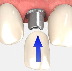
95 cement-retained single crowns using cementable abutments

96 cement-retained restorations cement-retained single crowns using cementable abutments Cement-retained implant restorations are similar to conventional crowns and bridges. Crowns and bridges are fabricated indirectly in the laboratory and cemented onto an implant abutment intraorally. Use this technique for a laboratory-modified cementable abutment. The clinician makes an implant-level impression; the lab prepares the abutment and fabricates the restoration. component options 3inOne abutments angled abutments angled esthetic abutments narrow emergence abutments straight esthetic abutments.050 (1.25mm) hex driver torque wrench abutment prepping handle abutment clamp 1 Make an implant-level impression Remove the healing abutment and follow the steps for creating an implant-level impression following either the open tray technique using the direct pick-up coping module or the closed tray technique using the indirect transfer coping module. 2 Lab step - Pour the working model Fabricate a working model following conventional laboratory procedures. A soft tissue model is recommended whenever the margins are subgingival. Follow the steps for creating an implant-level stone model in either the open tray technique using the direct pick-up coping module or the closed tray technique using the indirect transfer coping module. L REV D AUG 2016 Page 1 of 4
 hex driver.")


97 cement-retained restorations cement-retained single crowns using cementable abutments 3 Lab step - Select and mark the abutment Select an abutment based on implant location, tissue depth and doctor preference. Seat the abutment, engaging the hex of the implant analog in the mounted working model. Hand tighten the abutment screw with an.050 (1.25mm) hex driver. Evaluate inter-occlusal dimensions, angulations, and tissue contour. Mark the abutment for the required vertical reduction and gingival contour. Note: Allow a minimum of mm of occlusal clearance for metal and porcelain. 4 Lab step - Modify the abutment Place the marked abutment onto the appropriate abutment prepping handle and modify the abutment using carbide burs, cut-off disks, or heatless stone wheels. A diamond bur may be used to define the margins. Note: Create an axial groove to indicate the buccal surface for re-indexing the abutment in the mouth. If the flat of the abutment is removed during the preparation, a new anti-rotational feature must be established on the abutment. Important: For cement-retained restorations, maintain at least 3mm from the abutment platform to avoid damaging the abutment screw. 5 Lab step - Return the abutment to the model Return the modified abutment to the mounted working model and make final adjustments. A diamond bur may be used to modify and finesse margins. Important : When preparing a margin on an abutment for cement retention, it is important to respect the soft tissue contours rather than the pre-defined margin of the abutment. The abutment should be modified so the margin is 0.5mm to 1mm subgingival in the esthetic zone and at or above the gingiva in non-esthetic areas. Three examples of margin placement on a 3inOne abutment are shown on the right. L REV D AUG 2016 Page 2 of 4


98 cement-retained restorations cement-retained single crowns using cementable abutments 6 Lab step - Wax the coping, sprue, invest and cast In preparation to wax and cast the coping, block out the screw-access hole of the prepared abutment and apply die spacer. Create a wax coping for the crown on the modified abutment utilizing routine crown & bridge procedures. Sprue, invest and cast the coping pattern in noble or high noble alloy according to the manufacturer s instructions. 7 Lab step - Divest and finish the coping Divest, fit, and finish the cast coping following conventional laboratory techniques in preparation for porcelain application. 8 Lab step - Fabricate the crown Apply opaque and porcelain to the metal framework and complete the crown according to routine laboratory procedures. send to clinician finished crown modified abutment and abutment screw working model impression coping L REV D AUG 2016 Page 3 of 4
 hex driver. Make sure the implant prosthetic platform is free of bone and soft tissue.")

 hex driver. Apply counter-torque by grasping the abutment with an abutment clamp.")
99 cement-retained restorations cement-retained single crowns using cementable abutments 9 Seat the prepared abutment Sanitize modified abutment and crown per standard clinical procedure. Remove the healing abutment or provisional prosthesis from the implant with an.050 (1.25mm) hex driver. Make sure the implant prosthetic platform is free of bone and soft tissue. Irrigate the internally-threaded connection of the implant and dry. Place the modified abutment and abutment screw onto the implant with an.050 (1.25mm) hex driver and hand tighten. Take a radiograph along the long axis of the implant to ensure the abutment is seated completely in the hex of the implant. Note: The X-ray tube must be positioned perpendicular to the implant prosthetic platform. 10 Tighten the abutment screw Tighten the abutment screw to 30 Ncm using a calibrated torque wrench and an.050 (1.25) hex driver. Apply counter-torque by grasping the abutment with an abutment clamp. 11 Cement the final crown Place a resilient material of choice (gutta-percha, silicone or temporary filling material) into the screw access hole and fill the remaining channel with composite or another material of choice. This allows for easy access to the abutment screw in the future. Place the final restoration onto the abutment prior to cementation. Check the occlusion and contacts. There should only be light contact in centric occlusion and no contact in lateral excursions. Modify as necessary and polish after making adjustments. Important: Cement the crown following the crown cementation technique module Take an x-ray for final prosthesis delivery records. L REV D AUG 2016 Page 4 of 4


100 cement-retained restorations cement-retained bridge using cementable abutments Cement-retained implant restorations are similar to conventional crown and bridge restorations. Bridges are fabricated indirectly in the laboratory and cemented onto implant abutments intraorally. Use this technique for laboratory-modified cementable abutments. The clinician makes an implant-level impression; the lab prepares the abutments and fabricates the restoration. component options 3inOne abutments angled abutments angled esthetic abutments narrow emergence abutments straight esthetic abutments.050 (1.25mm) hex driver abutment clamp torque wrench abutment prepping handle 1 Make an implant-level impression Remove the healing abutments and follow the steps for creating an implant-level impression using either the open tray technique using the direct pick-up coping module or the closed tray technique using the indirect transfer coping module. 2 Lab step - Pour the working model Fabricate a working model following conventional laboratory procedures. A soft tissue model is recommended whenever the margins are subgingival. Follow the steps for creating an implant-level stone model (hexed) using either the open tray technique using the direct pick-up coping module or the closed tray technique using the indirect transfer coping module. L REV D AUG 2016 Page 1 of 5
 hex driver.")


101 cement-retained restorations cement-retained bridge using cementable abutments 3 Lab step - Select and mark the abutments Select the abutments based on implant location, tissue depth and doctor preference. Seat the abutments, engaging the hex of the implant analogs in the mounted working model. Hand tighten the abutment screws using an.050 (1.25mm) hex driver. Evaluate interocclusal dimensions, angulations, and tissue contour. Mark the abutments for the necessary vertical reduction and gingival contour. Note: A minimum of mm of occlusal clearance is required for metal and porcelain. 4 Lab step - Modify the abutments Place each marked abutment onto the appropriate abutment prepping handle and modify using carbide burs, cut-off disks, or heatless stone wheels. A diamond bur may be used to define the margins. Add a vertical groove to indicate the buccal surface for re-indexing the abutments in the mouth. 5 Lab step - Return to the model Seat the modified abutment to the mounted working model and make final adjustments. A diamond bur may be used to modify the margins. Important : When preparing a margin on an abutment for cement retention, it is important to respect the soft tissue contours rather than the pre-defined margin of the abutment. The abutment should be modified so the margin is 0.5mm to 1mm subgingival in the esthetic zone and at or above the gingiva in non-esthetic areas. Three examples of margin placement on a 3inOne abutment are shown on the right. L REV D AUG 2016 Page 2 of 5


102 cement-retained restorations cement-retained bridge using cementable abutments 6 Lab step - Wax the framework, sprue, invest and cast In preparation to wax and cast the coping, block out the screw-access holes of the prepared abutments and apply die spacer. Create a wax framework for the bridge on the modified abutments utilizing routine crown & bridge procedures. Sprue, invest and cast the wax pattern in noble or high noble alloy according to manufacturer s instructions. 7 Lab step - Divest and finish the cast framework Divest, fit, and finish the cast framework following conventional laboratory techniques. Confirm the framework fits passively on the modified abutments. Send to the clinician for framework try-in. send to clinician cast framework modified abutments and abutment screws working model impression copings 8 Seat the abutments Sanitize the abutments and bridge framework per standard clinical procedures. Remove the healing abutments or provisional restorations from the implants using an.050 (1.25mm) hex driver. Make sure the implant prosthetic platforms are free of bone and soft tissue. Irrigate the internal connection of the implants and dry. Place the modified abutments and abutment screws onto the implants using an.050 (1.25mm) hex driver and hand tighten. Take a radiograph along the long axis of the implants to ensure that the abutments are seated completely. Note: The X-ray tube must be positioned perpendicular to the implant prosthetic platform. L REV D AUG 2016 Page 3 of 5


103 cement-retained restorations cement-retained bridge using cementable abutments 9 Try in the bridge framework Try in the bridge framework. Confirm a passive fit and that no additional adjustments are necessary. Remove the bridge framework. Remove the modified abutments, one at a time, replacing them with the healing abutments or temporary prosthesis. send to lab metal framework modified abutments and abutment screws working model prescription with lab instructions 10 Lab step - Fabricate the crown Apply opaque and porcelain to the metal framework and complete according to routine laboratory procedures. send to clinician finished bridge modified abutments and abutment screws working model impression copings 11 Seat the prepared abutments Sanitize the modified abutments and bridge per standard clinical procedures. Remove the healing abutments or provisional prosthesis from the implants using an.050 (1.25mm) hex driver. Make sure the implant prosthetic platforms are free of bone and soft tissue. Irrigate the internal connection of the implants and dry. Place the modified abutments and abutment screws onto the implant using an.050 (1.25mm) hex driver and hand tighten. Take a radiograph along the long axis of the implant to ensure that the abutment is seated completely. Note: The X-ray tube must be positioned perpendicular to the implant prosthetic platform. L REV D AUG 2016 Page 4 of 5
 hex driver. Apply counter-torque by grasping the abutment using an abutment clamp.")
104 cement-retained restorations cement-retained bridge using cementable abutments 12 Tighten the abutment screws Tighten the abutment screws to 30 Ncm using a calibrated torque wrench and an.050 (1.25) hex driver. Apply counter-torque by grasping the abutment using an abutment clamp. 13 Cement the bridge Place a resilient material of choice (gutta-percha, silicone or temporary filling material) into the screw access holes and fill the remaining channels with composite or another material of choice. This allows for easy access to the abutment screws in the future. Place the final restoration onto the abutments prior to cementation. Check the occlusion and contacts. There should only be light contact in centric occlusion and no contact in lateral excursions. Modify as necessary and polish after making adjustments. Important: Cement the bridge following the crown cementation technique module. Take an x-ray for final prosthesis delivery records. L REV D AUG 2016 Page 5 of 5

 hex driver torque wrench abutment prepping handle abutment clamp 1 Remove the healing abutment and seat the selected abutment Remove the healing abutment or temporary prosthesis from the")
 hex driver). The emergence of the abutment should match the emergence of the healing abutment.")
105 cement-retained restorations chairside modification of cement-retained abutments Use this technique for modifying abutments chairside. Chairside modification of cement retained abutments for single or multi unit restorations is used when conventional crown and bridge is preferred. A single unit is depicted below. component options 3inOne abutments angled abutments angled esthetic abutments narrow emergence abutments straight esthetic abutments.050 (1.25mm) hex driver torque wrench abutment prepping handle abutment clamp 1 Remove the healing abutment and seat the selected abutment Remove the healing abutment or temporary prosthesis from the implant with an.050 (1.25mm) hex driver. Make sure the implant prosthetic platform is free of bone and soft tissue. Place the selected abutment onto the implant and hand tighten the abutment screw with an.050 (1.25mm) hex driver). The emergence of the abutment should match the emergence of the healing abutment. 2 Mark the abutment for modification Check the inter-occlusal dimension and angulations. Mark the required modifications for vertical clearance and gingival contours. Note: Allow a minimum of mm of occlusal clearance for metal and porcelain. Important: For cement-retained restorations, maintain at least 3mm from the abutment platform to avoid damaging the abutment screw. 3 Remove the abutment and replace the healing abutment Remove the marked abutment and immediately replace the healing abutment or temporary prosthesis onto the implant to prevent soft tissue collapse over the implant. L REV D AUG 2016 Page 1 of 4
106 cement-retained restorations chairside modification of cement-retained abutments 4 Modify the abutment Place the abutment onto the appropriate abutment prepping handle. Modify the abutment using carbide burs, cut-off disks, or heatless stone wheels. A diamond bur may be used to define the margins. Note: Create an axial groove to indicate the buccal surface for re-indexing the abutment in the mouth. If the flat of the abutment is removed during the preparation, a new anti-rotational feature must be established on the abutment. Important : When preparing a margin on an abutment for cement retention, it is important to respect the soft tissue contours rather than the pre-defined margin of the abutment. The abutment should be modified so the margin is 0.5mm to 1mm subgingival in the esthetic zone and at or above the gingiva in non-esthetic areas. Three examples of margin placement on a 3inOne abutment are shown on the right. 5 Seat the modified abutment Remove the healing abutment or temporary prosthesis from the implant with an.050 (1.25mm) hex driver. Make sure the implant prosthetic platform is free of bone and soft tissue. Irrigate the internally-threaded connection of the implant and dry. Seat the modified abutment and hand tighten with an.050 (1.25mm) hex driver. Take a radiograph along the long axis of the implant to ensure the abutment is seated completely in the hex of the implant. Note: The X-ray tube must be positioned perpendicular to the implant prosthetic platform Tighten the abutment screw to 30 Ncm. Apply counter-torque by grasping the abutment with an abutment clamp. Note: Minor intra-oral adjustments may be necessary. Use copious amounts of irrigation to eliminate excessive heat buildup in the surrounding bone tissue that may compromise the osseointegration of the implant. Use carbide or coarse diamond burs. L REV D AUG 2016 Page 2 of 4
107 cement-retained restorations chairside modification of cement-retained abutments 6 Make a full-arch impression Place a resilient material of choice (gutta-percha, silicone or temporary filling material) into the screw access channel. This allows for easy access to the abutment screw in the future. Syringe medium or heavy-bodied impression material around prepared abutment and in the impression tray. Make a conventional crown & bridge impression. Note: Retraction cord or injectable retraction medium may be necessary to record the margin prepared on the abutment. 7 Make the temporary Prepare and cement the provisional crown using the technique and a material of choice. Try in temporary crown and check the occlusion and contacts. There should only be light contact in centric occlusion and no contact in lateral excursions. Modify as necessary and polish after making adjustments. Important: Cement the temporary crown following the crown cementation technique module send to lab impression bite registration opposing model or impression prescription with lab instructions 8 Lab step - Pour the working model Pour a working model in minimal expansion, high hardness die stone and articulate according to standard laboratory procedures. Note: The remaining dental laboratory procedures utilize conventional crown and bridge techniques. L REV D AUG 2016 Page 3 of 4

108 cement-retained restorations chairside modification of cement-retained abutments 9 Remove the temporary Sanitize the final prosthesis following a standard clinical protocol. Remove the provisional prosthesis. Make sure the abutment and margins are free of all temporary cement for complete seating of the final crown. 10 Cement the crown Place the final restoration onto the abutment prior to cementation. Check the occlusion and contacts. There should only be light contact in centric occlusion and no contact in lateral excursions. Modify as necessary and polish after making adjustments. Important: Cement the crown following the crown cementation technique module. Take an x-ray for final prosthesis delivery records. L REV D AUG 2016 Page 4 of 4

 hex driver torque wrench 1 Make an implant-level impression Follow the steps for creating an implant-level impression using either the open tray technique using the direct pick-up coping module")
109 screw-retained restorations screw-retained single crowns using custom-cast abutments The custom castable abutment, hexed (UCLA) offers the clinician the option of making a custom crown that is screw-retained onto the implant. Use this technique for a lab-fabricated, custom, screw-retained crown. The custom crown can complement soft tissue contour and height and can also correct angulation. component options custom castable (UCLA) abutment, hexed.050 (1.25mm) hex driver torque wrench 1 Make an implant-level impression Follow the steps for creating an implant-level impression using either the open tray technique using the direct pick-up coping module or the closed tray technique using the indirect transfer coping module. 2 Lab step - Pour the working model Fabricate a working model following conventional laboratory procedures. A soft tissue model is recommended whenever the margins are subgingival. Follow the steps for creating an implant-level stone model (hexed) using either the open tray technique using the direct pick-up coping module or the closed tray technique using the indirect transfer coping module. 3 Lab step - Seat, mark, and modify the abutment Seat the selected custom castable abutment onto the implant analog in the working model. Hand tighten the abutment screw with an.050 (1.25mm) hex driver. Determine modifications needed to provide adequate room for the fabrication of the crown. Modify the plastic sleeve of the abutment with a cutting disk or an acrylic bur for correct vertical and interproximal clearances. Modify height leaving the sleeve out of occlusion 1-2 mm. Important: For screw-retained restorations, maintain at least 3mm from the abutment platform to avoid damaging the abutment screw. L REV D AUG 2016 Page 1 of 4


110 screw-retained restorations screw-retained single crowns using custom-cast abutments 4 Lab step - Wax the custom abutment Use wax and/or acrylic burnout resin to incorporate the modified custom castable abutment into the pattern. The final contours of the pattern may be built up with crown & bridge wax. 5 Lab step - Sprue, invest and cast the abutment Sprue, invest and cast the abutment pattern in noble or high noble alloy according to manufacturer s instructions. When investing, pour the investment into the ring very slowly to insure the investment flows up through the screw access hole. Note: custom castable gold alloy specifications* Melting range: C Coefficient of thermal expansion: 12.2x10⁻⁶ K -1 Hardness HV5: >215 Tensile Strength: >750 MPa Composition: 60% Gold, 20% Platinum, 19% Palladium, 1% Iridium * Material Data Sheet for Ceramicor from Centres+Métaux 6 Lab step - Divest, fit, and finish the abutment Divest, fit, and finish the casting following conventional laboratory techniques. Important: When divesting the casting, it is important not to sandblast the implant/abutment interface. Doing so may result in a poor fit between the abutment and the implant. Use of a chemical investment remover is recommended to preserve the precision fit. Confirm the cast abutment on the working model. L REV D AUG 2016 Page 2 of 4


111 screw-retained restorations screw-retained single crowns using custom-cast abutments 7 Lab step - Apply the porcelain Prepare the cast abutment to receive the opaque layer according to routine laboratory procedures. Apply porcelain and finish according to routine laboratory procedures. Note: When applying porcelain, use caution not to get any porcelain into the screw-access holes. Polish any metal margins as is routine. Seat the finished crown onto the analog on the working model and send to clinician for patient delivery. send to clinician crown abutment screw working model 8 Seat the final restoration Sanitize the finished crown using standard clinical procedure. Remove the healing abutment or temporary prosthesis from the implant with an.050 (1.25mm) hex driver. Make sure the implant prosthetic platform is free of bone and soft tissue. Irrigate the internally-threaded connection of the implant and dry. Secure the crown onto the implant using the abutment screw and an.050 (1.25mm) hex driver. Hand tighten. 9 Check and modify the restoration Check the occlusion and contacts. There should only be light contact in centric occlusion and no contact in lateral excursions. Modify as necessary and polish after making adjustments. Take a radiograph along the long axis of the implant to ensure that the crown is seated completely in the hex of the implant. Note: The X-ray tube must be positioned perpendicular to the implant prosthetic platform. L REV D AUG 2016 Page 3 of 4
 hex driver and a calibrated torque wrench.")

112 screw-retained restorations screw-retained single crowns using custom-cast abutments 10 Tighten the abutment screw Tighten the abutment screw to 30 Ncm using an.050 (1.25mm) hex driver and a calibrated torque wrench. 11 Fill the screw access channel Place a resilient material of choice (gutta-percha, silicone or temporary filling material) into the screw access channel. This allows for easy access to the abutment screw in the future. Fill the remainder of the channel with a composite resin material of choice. Take an x-ray for final prosthesis delivery records. L REV D AUG 2016 Page 4 of 4

 hex driver Ncm torque wrench 1 Make an impression Follow the steps for creating an implant-level impression using either the open tray technique using the direct pick-up coping module or the")
113 screw-retained restorations screw-retained bridge using custom-cast abutments The custom castable abutment, non-hexed (UCLA) offers the clinician the option of making a custom bridge that is screw-retained onto implants. Use this technique for a lab-fabricated, custom, screw-retained bridge. The custom bridge can complement soft tissue contour and height and can also correct angulation. component options custom castable (UCLA) abutment, non-hexed.050 (1.25mm) hex driver Ncm torque wrench 1 Make an impression Follow the steps for creating an implant-level impression using either the open tray technique using the direct pick-up coping module or the closed tray technique using the indirect transfer coping module. 2 Lab step - Pour the working model Fabricate a working model following conventional laboratory procedures. A soft tissue model is recommended whenever the margins are subgingival. Follow the steps for creating an implant-level stone model using either the open tray technique using the direct pick-up coping module or the closed tray technique using the indirect transfer coping module. 3 Lab step - Seat, mark, and modify the abutments Seat the selected non-hexed, custom castable abutments onto the implant analogs in the working cast. Hand tighten the abutment screws with an.050 (1.25mm) hex driver. Determine modifications needed to provide adequate room for the fabrication of bridge. Modify the plastic sleeves of the abutments with a cutting disk or an acrylic bur for correct vertical and interproximal clearances. Modify height leaving the sleeve out of occlusion 1-2 mm. Important: For screw-retained restorations, maintain at least 3mm from the abutment platform to avoid damaging the abutment screw. L REV D AUG 2016 Page 1 of 5


114 screw-retained restorations screw-retained bridge using custom-cast abutments 4 Lab step - Wax the custom framework Use wax and/or acrylic burnout resin to incorporate the modified custom castable abutments into the pattern. The final contours of the pattern may be built up with crown & bridge wax. 5 Lab step - Sprue, invest and cast the framework Sprue, invest and cast the wax frame in noble or high noble alloy according to manufacturer s instructions. When investing, pour the investment into the ring very slowly to insure the investment flows up through the screw access holes. Note: custom castable gold alloy specifications* Melting range: C Coefficient of thermal expansion: 12.2x10⁻⁶ K -1 Hardness HV5: >215 Tensile Strength: >750 MPa Composition: 60% Gold, 20% Platinum, 19% Palladium, 1% Iridium * Material Data Sheet for Ceramicor from Centres+Métaux 6 Lab step - Divest, fit, and finish the framework Divest, fit, and finish the casting following conventional laboratory techniques. Important: When divesting the casting, it is important not to sandblast the implant/abutment interface. Doing so may result in a poor fit between the abutments and the implants. Use of a chemical investment remover is recommended to preserve the precision fit. Note: A metal try-in is recommended for 3 or more units to confirm a passive fit of the framework prior to porcelain application. L REV D AUG 2016 Page 2 of 5
 hex driver.")
 hex driver. Hand tighten.")
115 screw-retained restorations screw-retained bridge using custom-cast abutments send to clinician metal framework abutment screws working model 7 Try-in the metal framework Sanitize the bridge framework using standard clinical procedure. Remove the healing abutments or temporary restoration from the implants with an.050 (1.25mm) hex driver. Make sure the implant prosthetic platforms are free of bone and soft tissue. Irrigate the internally-threaded connection of the implants and dry. Secure the custom bridge framework onto the implants using the abutment screws and an.050 (1.25mm) hex driver. Hand tighten. 8 Take an X-ray and confirm fit Take a radiograph along the long axis of the implants to ensure the framework is seated completely on the implants. Note: The X-ray tube must be positioned perpendicular to the implant prosthetic platform. Confirm a passive fit of the framework. If the framework is not passive, section and relate in the mouth using resin material. Send to the lab for soldering/laser welding. Remove framework, replace the healing abutments or temporary restoration, and return to the lab for porcelain application. send to lab metal framework abutment screws working model prescription with lab instructions L REV D AUG 2016 Page 3 of 5


116 screw-retained restorations screw-retained bridge using custom-cast abutments 9 Lab step - Apply the porcelain Apply opaque and porcelain to the metal framework and complete according to routine laboratory procedures. Note: When applying porcelain, use caution not to get any porcelain into the screw-access holes. Polish any metal margins as is routine. Implant analogs may be used to protect the connection during polishing. Secure the finished bridge onto the analogs on the working model and send to clinician for patient delivery. send to clinician finished bridge abutment screws working model 10 Seat the final restoration Sanitize the finished bridge using standard clinical procedure. Remove the healing abutments or temporary restoration from the implants using an.050 (1.25mm) hex driver. Make sure the implant prosthetic platforms are free of bone and soft tissue. Irrigate the internally-threaded connection of the implants and dry. Secure the bridge onto the implants using the abutment screws and an.050 (1.25mm) hex driver. Hand tighten. 11 Check and modify the restoration Check the occlusion and contacts. There should only be light contact in centric occlusion and no contact in lateral excursions. Modify as necessary and polish after making adjustments. Take a radiograph along the long axis of the implants to ensure that the bridge is seated completely onto the implants. Note: The X-ray tube must be positioned perpendicular to the implant prosthetic platform. L REV D AUG 2016 Page 4 of 5
 hex driver and a calibrated torque wrench.")

117 screw-retained restorations screw-retained bridge using custom-cast abutments 12 Tighten the abutment screws Tighten the abutment screws to 30 Ncm using an.050 (1.25mm) hex driver and a calibrated torque wrench. 13 Fill the screw access channels Place a resilient material of choice (gutta-percha, silicone or temporary filling material) into screw access channels. This allows for easy access to the abutment screws in the future. Fill the remainder of the channels with a composite resin material of choice. Take an x-ray for final prosthesis delivery records. L REV D AUG 2016 Page 5 of 5
118 full-arch restorations Multi-unit abutment hybrid or fixed-detachable screw-retained restoration Use this technique for the fabrication of a multiple unit implant-supported, screw-retained hybrid in a partially or fully edentulous patient. component options Multi-unit abutments, straight Multi-unit abutments, angled Multi-unit direct pick-up copings Multi-unit abutment replicas Multi-unit protection analogs Multi-unit abutment prosthetic screws Multi-unit abutment cover caps manual Multi-unit hex adapter handpiece Multi-unit hex adapter 4mm square Multi-unit hex adapter.050 (1.25mm) hex driver torque wrench 1 Select the abutments Measure the tissue depth from the top of the implant to the top of the tissue at its highest point. Select a Multiunit abutment with a collar height which is 1-2mm taller than what is measured and also matches the platform size and angulation needed for proper coping position. L REV D AUG 2016 Page 1 of 9
119 full-arch restorations Multi-unit abutment hybrid or fixed-detachable screw-retained restoration 2 Place the abutments Remove the healing abutments using an.050 (1.25mm) hex driver. Straight abutments: Seat each straight abutment using the color-coded carrier, threading it clockwise onto the implant body. Bend the carrier to release it from the abutment. Hand tighten the abutment using the manual Multi-unit hex adapter. Angled abutments: Remove the color-coded carrier from the angled abutment using an.050 (1.25mm) hex driver. Deliver the abutment to the implant using the hex driver (for convenient, one-handed placement) or the Multi-unit carrier (for controlled, two-handed placement). The Multi-unit carrier is sold separately. Hand tighten the abutment screw. Important: When placing an angled Multi-unit abutment, rotate the abutment and choose one of the six positions that best corrects the implant angle. Helpful Hint: Remove one healing abutment at a time and immediately replace it with a Multi-unit abutment. This reduces the likelihood of soft tissue collapsing onto the implant. Work from the posterior to the anterior. Take a radiograph along the long axis of the implants to ensure that the Multi-unit abutments are seated completely. Note: The X-ray tube must be positioned perpendicular to the implant prosthetic platform. Straight abutments: Tighten the abutments to 30 Ncm using a calibrated torque wrench and the 4mm square hex adapter. The Multi-unit handpiece hex adapter can be used with a compatible torque wrench. Angled abutments: Tighten the abutments to 30 Ncm using a calibrated torque wrench and an.050 (1.25) hex driver. L REV D AUG 2016 Page 2 of 9

120 full-arch restorations Multi-unit abutment hybrid or fixed-detachable screw-retained restoration 3 Make an abutment-level impression Follow the steps for creating an abutment-level impression by referring to the impression technique for either the Multi-unit abutment open tray technique using the direct pick-up coping module or the Multiunit abutment closed tray technique using the indirect transfer coping module. Important: The fabrication of a verification jig is recommended to ensure the accuracy of the master stone model. Follow the steps for creating a verification jig by referring to the verification jig fabrication module. 4 Lab step - Make a stabilized baseplate Place the Multi-unit direct pick-up copings on the model using the long prosthetic screws. Place a baseplate material of choice around the copings. Contour the material around the copings and posterior along the edentulous arch. This will be used to stabilize the wax rim. 5 Lab step - Create a wax occlusal rim Create a wax occlusal rim on the stabilized baseplate allowing access to the screws. Only two screws in the cuspid areas are needed to secure the assembly to the model. Index the occlusal rim to stabilize bite registration material used in next step. send to clinician stabilized baseplate model regular prosthetic screws L REV D AUG 2016 Page 3 of 9
 hex driver. Attach the baseplate and occlusal rim assembly to the abutments using the regular Multi-unit prosthetic screws and hand tighten using an.050 (1.25mm) hex driver. Contour the occlusal rim, mark the midline, and smile line.")


121 full-arch restorations Multi-unit abutment hybrid or fixed-detachable screw-retained restoration 6 Try-in the stabilized baseplate Remove the cover caps from the Multi-unit abutments using an.050 (1.25mm) hex driver. Attach the baseplate and occlusal rim assembly to the abutments using the regular Multi-unit prosthetic screws and hand tighten using an.050 (1.25mm) hex driver. Contour the occlusal rim, mark the midline, and smile line. Record the vertical dimension of the occlusion with a bite registration material. 7 Attach the baseplate to the working model Remove the baseplate and the bite registration from the mouth and reassemble on the working model using the Multi-unit prosthetic screws. Replace the healing caps onto the abutments using an.050 (1.25mm) hex driver. Note: If making a verification jig, refer to verification jig fabrication module. Return the case to the laboratory for the fabrication of a trial hybrid denture. send to lab tooth selection occlusal rim bite registration models prescription with lab instructions 8 Lab step - Mount and set the teeth Mount the working and opposing model on an articulator. Set denture teeth on the wax rim and wax for try-in. Adjust the teeth as necessary to clear the screw access holes. Finish for a trial hybrid denture. send to clinician trial hybrid denture mounted on working cast regular prosthetic screws L REV D AUG 2016 Page 4 of 9
 hex driver. Seat the hybrid denture try-in onto the Multi-unit abutments and place the prosthetic screws through the two access holes in the denture. Hand tighten using an.050 (1.25mm) hex driver. 10 Verify the trial hybrid denture Verify occlusion, esthetics, and phonetics.")


122 full-arch restorations Multi-unit abutment hybrid or fixed-detachable screw-retained restoration 9 Try in the trial hybrid denture Remove the healing caps from the Multi-unit abutments using an.050 (1.25mm) hex driver. Seat the hybrid denture try-in onto the Multi-unit abutments and place the prosthetic screws through the two access holes in the denture. Hand tighten using an.050 (1.25mm) hex driver. 10 Verify the trial hybrid denture Verify occlusion, esthetics, and phonetics. It may be necessary to make adjustments and new inter-occlusal records for a new try-in. Remove the trial hybrid denture and replace the healing caps using an.050 (1.25mm) hex driver. Replace the trial hybrid denture onto the working model and secure. send to lab trial hybrid denture mounted on working model new inter-occlusal records, if necessary 11 Lab step - Form a matrix Index the working model with circular grooves or notches to allow for accurate repositioning of the lab matrix putty. Make a labial matrix of the denture teeth in silicone putty to record tooth position and labial borders of the prosthesis relative to the working model. Remove the teeth from the wax-up and place them into their respective locations in the silicone putty matrix. Lute them into position with sticky wax. L REV D AUG 2016 Page 5 of 9


123 full-arch restorations Multi-unit abutment hybrid or fixed-detachable screw-retained restoration 12 Lab step - Place the copings Place the gold custom castable copings for the Multiunit abutment on the working model. Position the matrix with the teeth onto the working model and use it as a guide for modifying the copings. Design the frame within the confines of the trial hybrid denture teeth. Connect the copings using an acrylic resin material to serve as a foundation for the frame wax-up. 13 Lab step - Wax the framework Wax the framework to follow and support the position of the teeth. Keep the frame 2-3 mm off the tissue for adequate hygiene space. Following completion of the wax-up, add retention beads and loops to retain the acrylic. Note: custom castable gold alloy specifications* Melting range: C Coefficient of thermal expansion: 12.2x10⁻⁶ K -1 Hardness HV5: >215 Tensile strength: >750 MPa Composition: 60% gold, 20% platinum, 19% palladium, 1% iridium * material data sheet for Ceramicor from Centres+Métaux 14 Lab step - Sprue, invest and cast the framework Sprue and invest the wax pattern per normal laboratory procedures. Cast the frame in a noble or high noble alloy. Important: Do not use a non-precious alloy. L REV D AUG 2016 Page 6 of 9

124 full-arch restorations Multi-unit abutment hybrid or fixed-detachable screw-retained restoration 15 Lab step - Divest, finish, and polish the framework Divest the frame. Important: When divesting the casting, it is important not to sandblast the abutment interface. Doing so may result in a poor fit between the abutment and the frame. Using a chemical investment remover is preferred. When polishing the interface between the abutment and the prosthetic connection, attach a Multi-unit protection analog to protect the connection. Finish the casting and check for a passive fit. Section and solder/laser weld as needed. Polish the frame, again using the protection analog. Send to the clinician for try-in. send to clinician hybrid frame regular prosthetic screws working model 16 Try-in the framework Remove the healing caps from the Multi-unit abutments using an.050 (1.25mm) hex driver. Place the hybrid frame and confirm that it seats passively. Beginning with the most distal implant, place the first prosthetic screw. Hand tighten the screw and make sure the abutment interface/connections on all the remaining implants are completely seated. Continue placing the prosthetic screws. Verify the fit each time a screw is placed. If at any point the frame lifts as a screw is tightened, the frame is not passive and needs to be sectioned in this area and returned to the lab for correction. Refer to the correcting a nonpassive framework module. Remove the hybrid framework. Replace the healing caps onto the Multi-unit abutments using an.050 (1.25mm) hex driver. send to lab hybrid frame prescription with lab instructions working model L REV D AUG 2016 Page 7 of 9

 hex driver. Place the trial hybrid denture and verify occlusion, esthetics, and phonetics. Make any necessary adjustments and take a new bite registration if needed.")
125 full-arch restorations Multi-unit abutment hybrid or fixed-detachable screw-retained restoration 17 Lab step - Wax set-up Set-up the denture teeth in wax following conventional denture procedures and send to the clinician for a trial hybrid denture. send to clinician hybrid frame with teeth set up in wax regular prosthetic screws working model 18 Trial hybrid denture try-in Remove the healing caps from the Multi-unit abutments using an.050 (1.25mm) hex driver. Place the trial hybrid denture and verify occlusion, esthetics, and phonetics. Make any necessary adjustments and take a new bite registration if needed. Remove the hybrid denture and replace the healing caps onto the Multi-unit abutments using an.050 (1.25mm) hex driver. Send to the lab for final processing. send to lab trial hybrid denture prescription with lab instructions working model regular prosthetic screws bite registration 19 Lab step - Final processing Process acrylic using conventional denture procedures. Use the long prosthetic screws during processing. This will maintain the screw access holes. send to clinician completed hybrid prosthesis regular prosthetic screws working model L REV D AUG 2016 Page 8 of 9
 hex driver. Place the hybrid prosthesis and confirm that it seats passively. Beginning with the most distal implant, place the first prosthetic screw.")
 hex driver and a calibrated torque wrench.")
 into the screw access channel.")
126 full-arch restorations Multi-unit abutment hybrid or fixed-detachable screw-retained restoration 20 Deliver the final restoration Remove the healing caps from the Multi-unit abutments using an.050 (1.25mm) hex driver. Place the hybrid prosthesis and confirm that it seats passively. Beginning with the most distal implant, place the first prosthetic screw. Hand tighten the screw and make sure the connections to all the remaining abutments are completely seated. Verify occlusion, esthetics, and phonetics. Modify as necessary and polish after making adjustments. 21 Tighten the prosthetic screws Tighten the prosthetic screws to 15 Ncm using an.050 (1.25mm) hex driver and a calibrated torque wrench. Important: Do not exceed 15 Ncm when tightening prosthetic screws onto the Multi-unit abutments. BioHorizons recommends the use of the ITL precision adjustment torque wrench. 22 Fill the screw access channels Place a resilient material of choice (gutta-percha, silicone or temporary filling material) into the screw access channel. This allows for easy access to the prosthetic screw in the future. Fill the remainder of the channels with a composite resin material of choice. Take an x-ray for final prosthesis delivery records. L REV D AUG 2016 Page 9 of 9

127 full-arch restorations Multi-unit abutment bar overdenture Use this technique for the fabrication of a multiple-unit, implant-supported, screw-retained bar with an overdenture in a totally edentulous patient. component options Multi-unit abutments, straight Multi-unit abutments, angled Multi-unit abutment cover cap manual Multi-unit hex adapter handpiece Multi-unit hex adapter 4mm square Multi-unit hex adapter.050 (1.25mm) hex driver torque wrench Multi-unit direct pick-up copings Multi-unit abutment replicas Multi-unit protection analog Multi-unit prosthetic screws 1 Select the abutments Measure the tissue depth from the top of the implant to the top of the tissue at its highest point. Select a Multiunit abutment with a collar height which is 1-2mm taller than what is measured and also matches the platform size and angulation needed for proper coping position. L REV D AUG 2016 Page 1 of 9

 or the Multi-unit carrier (for controlled, two-handed placement).")


128 full-arch restorations Multi-unit abutment bar overdenture 2 Place the abutments Remove the healing abutments using an.050 (1.25mm) hex driver. Straight abutments: Seat each straight abutment using the color-coded carrier, threading it clockwise onto the implant body. Bend the carrier to release it from the abutment. Hand tighten the abutment using the manual Multi-unit hex adapter. Angled abutments: Remove the color-coded carrier from the angled abutment using an.050 (1.25mm) hex driver. Deliver the abutment to the implant using the hex driver (for convenient, one-handed placement) or the Multi-unit carrier (for controlled, two-handed placement). The Multi-unit carrier is sold separately. Hand tighten the abutment screw. Important: When placing an angled Multi-unit abutment, rotate the abutment and choose one of the six positions that best corrects the implant angle. Helpful Hint: Remove one healing abutment at a time and immediately replace it with a Multi-unit abutment. This reduces the likelihood of soft tissue collapsing onto the implant. Work from the posterior to the anterior. Take a radiograph along the long axis of the implants to ensure that the Multi-unit abutments are seated completely. Note: The X-ray tube must be positioned perpendicular to the implant prosthetic platform. Straight abutments: Tighten the abutments to 30 Ncm using a calibrated torque wrench and the 4mm square hex adapter. The Multi-unit handpiece hex adapter can be used with a compatible torque wrench. Angled abutments: Tighten the abutments to 30 Ncm using a calibrated torque wrench and an.050 (1.25) hex driver. 3 Make an abutment-level impression Follow the steps for creating an abutment-level impression by referring to either the Multi-unit abutment open tray technique using the direct pick-up coping module or the Multi-unit abutment closed tray technique using the indirect transfer coping module. Important: The fabrication of a verification jig is recommended to ensure the accuracy of the master stone model. Follow the steps for creating a verification jig by referring to the verification jig fabrication module. L REV D AUG 2016 Page 2 of 9

129 full-arch restorations Multi-unit abutment bar overdenture 4 Lab step - Make a stabilized baseplate Place the Multi-unit direct pick-up copings on the model using the long prosthetic screws. Place a baseplate material of choice around the copings. Contour the material around the copings and posterior along the edentulous arch. This will be used to stabilize the wax rim later. 5 Lab step - Create a wax occlusal rim Create a wax occlusal rim on the stabilized baseplate allowing access to the screws. Only two screws in the cuspid areas are needed to secure the assembly to the model. Index the occlusal rim to stabilize bite registration material used in next step. send to clinician stabilized baseplate model regular prosthetic screws 6 Try-in the stabilized baseplate Remove the cover caps from the Multi-unit abutments using an.050 (1.25mm) hex driver. Attach the baseplate and occlusal rim assembly to the abutments using the regular Multi-unit prosthetic screws and hand tighten using an.050 (1.25mm) hex driver. Contour the occlusal rim, mark the midline, and smile line. Record the vertical dimension of the occlusion with bite registration material. L REV D AUG 2016 Page 3 of 9
 hex driver.")

130 full-arch restorations Multi-unit abutment bar overdenture 7 Attach the baseplate to the working model Remove the baseplate and the bite registration from the mouth and reassemble on the working model using the Multi-unit prosthetic screws. Replace the healing caps onto the abutments using an.050 (1.25mm) hex driver. Note: If making a verification jig, refer to verification jig fabrication module. Return the case to the laboratory for the fabrication of a stabilized trial denture. send to lab tooth selection occlusal rim bite registration models prescription with lab instructions 8 Lab step - Mount and set the teeth Mount the working and opposing model on an articulator. Set the denture teeth for a trial denture. Finish for a denture wax try-in. send to clinician trial denture for approval L REV D AUG 2016 Page 4 of 9


131 full-arch restorations Multi-unit abutment bar overdenture 9 Try in the trial denture Verify occlusion, esthetics, and phonetics. It may be necessary to make adjustments and new inter-occlusal records for a new try-in. send to lab trial denture new inter-occlusal records, if necessary 10 Lab step - Form a matrix Index the working model with circular grooves or notches to allow for accurate repositioning of the lab matrix putty. Make a labial matrix of the denture teeth in silicone putty to record tooth position and labial borders of the prosthesis relative to the working model. 11 Lab step - Place the copings and design the bar Place the gold custom castable copings for the Multiunit abutment on the working model. Position the matrix onto the working model and use it as a guide for modifying the copings. Design the bar within the confines of the wax try-in. L REV D AUG 2016 Page 5 of 9


132 full-arch restorations Multi-unit abutment bar overdenture 12 Lab step - Wax the bar Verify attachment position, bar height and functional requirements. Design the overdenture bar using a bar wax and/or a preformed pattern of choice, incorporating the copings within the bar pattern. Verify the position of attachments with a surveyor and adjust as needed. Note: custom castable gold alloy specifications* Melting range: C Coefficient of thermal expansion: 12.2x10⁻⁶ K -1 Hardness HV5: >215 Tensile strength: >750 MPa Composition: 60% gold, 20% platinum, 19% palladium, 1% iridium * material data sheet for Ceramicor from Centres+Métaux 13 Lab step - Sprue, invest and cast Sprue and invest the wax pattern per normal laboratory procedures. Cast the frame in a noble or high noble alloy. Important: Do not use a non-precious alloy. 14 Lab step - Divest, finish, and polish Divest the bar. Important: When divesting the casting, it is important not to sandblast the abutment interface. Doing so may result in a poor fit between the abutment and the bar. Using a chemical investment remover is preferred. When polishing the interface between the abutment and the bar connection, attach a Multi-unit protection analog to protect the connection. Finish the casting and check for a passive fit. Section and solder/laser weld as needed. Polish the bar, again using the protection analog. L REV D AUG 2016 Page 6 of 9
 hex driver. Adapt the wax-setup to fit over the bar and process the selected attachments into the denture base using normal laboratory procedures.")
133 full-arch restorations Multi-unit abutment bar overdenture 15 Process attachments in the denture base Attach the finished bar to the working model using the prosthetic screws and an.050 (1.25mm) hex driver. Adapt the wax-setup to fit over the bar and process the selected attachments into the denture base using normal laboratory procedures. send to clinician bar regular prosthetic screws trial denture working model 16 Try in the bar Remove the healing caps from the Multi-unit abutments using an.050 (1.25mm) hex driver. Place the bar on the Multi-unit abutments and confirm that the bar seats passively. Beginning with the most distal implant, place the first prosthetic screw. Hand tighten the screw and make sure the abutment interface/connections on all the remaining implants are completely seated. Continue placing the prosthetic screws. Verify the fit each time a screw is placed. If at any point the bar lifts as a screw is tightened, the bar is not passive and needs to be sectioned in this area and returned to the lab for correction. Refer to the correcting a non-passive framework module. L REV D AUG 2016 Page 7 of 9
 hex driver.")

134 full-arch restorations Multi-unit abutment bar overdenture 17 Try in the trial denture Place the trial denture on the bar and verify occlusion, esthetics, and phonetics. Make any necessary adjustments and take a new bite registration if needed. Remove the denture and the bar. Replace the healing caps onto the Multi-unit abutments using an.050 (1.25mm) hex driver. send to lab bar trial denture on the bar prescription with lab instructions working model regular prosthetic screws 18 Lab step - Process the denture Process the denture according to conventional laboratory procedures. send to clinician bar regular prosthetic screws finished denture working model 19 Deliver the final restoration Remove the healing caps from the Multi-unit abutments using an.050 (1.25mm) hex driver. Place the final cast bar and confirm that the bar seats passively. Beginning with the most distal implant, place the first prosthetic screw. Hand tighten the prosthetic screw using an.050 (1.25mm) hex driver. Make sure the connections to all the remaining abutments are completely seated. L REV D AUG 2016 Page 8 of 9
 hex driver and a calibrated torque wrench. Important: Do not exceed 15 Ncm when tightening prosthetic screws onto the Multi-unit abutments.")

135 full-arch restorations Multi-unit abutment bar overdenture 20 Tighten the prosthetic screws Tighten the prosthetic screws to 15 Ncm using an.050 (1.25mm) hex driver and a calibrated torque wrench. Important: Do not exceed 15 Ncm when tightening prosthetic screws onto the Multi-unit abutments. BioHorizons recommends the use of the ITL precision adjustment torque wrench. 21 Deliver the denture Seat the finished denture, engaging the attachments. Verify occlusion, esthetics, and phonetics. Modify as necessary and polish after making adjustments. Take an x-ray for final prosthetic delivery records. L REV D AUG 2016 Page 9 of 9
136 full-arch restorations verification jig fabrication Use this technique to verify and achieve passive fitting metal framework for a bridge, hybrid prosthesis or for an overdenture bar. A passive fit when splinting multiple implants together is suggested for implant-supported restorations. component options direct impression copings Multi-unit direct impression copings implant analogs Multi-unit abutment replicas.050 (1.25mm) hex driver Multi-unit prosthetic screws, long 1 Make an implant-level or Multi-unit abutment level impression Refer to one of the following modules that applies to the clinical situation: open tray technique using the direct pick-up coping closed tray technique using the indirect transfer coping Multi-unit abutment open tray technique using the direct pick-up coping Multi-unit abutment closed tray technique using the indirect transfer coping 2 Lab step - Pour the working model Fabricate a working model following conventional laboratory procedures. A soft tissue model is recommended whenever the margins are subgingival. Refer to one of the following modules that applies to the clinical situation: open tray technique using the direct pick-up coping closed tray technique using the indirect transfer coping Multi-unit abutment open tray technique using the direct pick-up coping Multi-unit abutment closed tray technique using the indirect transfer coping L REV D AUG 2016 Page 1 of 4

137 full-arch restorations verification jig fabrication 3 Lab step - Place the direct impression copings on the model Place implant-level or Multi-unit direct pick-up copings on the model using the long prosthetic screws. Note: As an alternative, titanium temporary abutments or Multi-unit titanium copings may be used for this procedure. 4 Lab step - Connect the impression copings Intertwine dental floss or orthodontic wire around the direct impression copings. Apply pattern resin or a light-cured material to the impression copings while incorporating the floss or wire, luting the impression copings together. Trim, shape, and smooth the acrylic as needed for try-in. Send the completed verification jig to the clinician for try-in. send to clinician verification jig abutment screws working model long abutment screws 5 Try-in the verification jig Remove the healing caps from the Multi-unit abutments or healing abutments from the implants using an.050 (1.25mm) hex driver. Confirm the prosthetic platform is free of any debris or soft tissue. Place the verification jig and confirm that it seats passively. Beginning with the most distal implant, place the first abutment screw. Hand tighten the screw and make sure the prosthetic interface on all the remaining implants are completely seated. Note: Visually or with a radiograph, always ensure the verification jig is completely seated onto the implants or the abutments. Continue placing the abutment screws. Verify the fit each time a screw is placed. If at any point the verification jig lifts as a screw is tightened, this indicates the jig is not passive and needs to be sectioned in that area. L REV D AUG 2016 Page 2 of 4
 hex driver.")

138 full-arch restorations verification jig fabrication 6 Section the verification jig Section the jig as necessary to create a passive fit and lute the sections together using acrylic or composite material. Remove the modified verification jig from the mouth and replace the cover caps or healing abutments using an.050 (1.25mm) hex driver. Return the luted verification jig to the laboratory for correction. Important: DO NOT ATTACH the verification jig to the model. send to lab luted verification jig abutment screws working model long abutment screws 7 Lab step - Correct the model Once the verification jig has been modified in the mouth, the working model must be corrected. Remove misaligned abutment replicas or implant analogs from the working model until the verification jig rests passively on the remaining replicas or analogs. 8 Lab step - Seat the jig on the model Attach the removed replicas or analogs to the verification jig and seat on the model securing it to the remaining replicas or analogs. The reattached replicas or analogs will be suspended within the hole created when they were removed from the model. Soak the model in water. L REV D AUG 2016 Page 3 of 4

139 full-arch restorations verification jig fabrication 9 Lab step - Modify the model Carefully vibrate stone into the voids around the retentive undercuts of the replicas or analogs. Allow the stone to set. Proceed with another try-in or continue with the case. L REV D AUG 2016 Page 4 of 4


140 full-arch restorations correcting a non-passive framework Use this technique to verify and achieve passive fitting metal framework for a bridge, hybrid prosthesis or for an overdenture bar. A passive fit when splinting multiple implants together is suggested for implant-supported restorations. 1 Try-in the frame Remove the healing caps from the Multi-unit abutments or healing abutments from the implants using an.050 (1.25mm) hex driver. Confirm that the prosthetic platform is free of any debris or soft tissue. Place the framework and confirm that the frame seats passively. Beginning with the most distal abutment or implant, place the first abutment screw. Hand tighten the screw and make sure the prosthetic interface on all the remaining abutments or implants is completely seated. Note: Visually or with a radiograph, always ensure the bar or framework is completely seated onto the abutments. Continue placing the abutment screws. Verify the fit each time a screw is placed. If at any point the frame lifts as a screw is tightened, this indicates the frame is not passive and needs to be sectioned in that area and returned to the lab for correction. 2 Mark and modify the framework Mark the area(s) that will require sectioning. Remove and section the framework where necessary. 3 Lute the sectioned framework Seat the sectioned frame and lute it together using acrylic/composite resin material. Note: Visually or with a radiograph, always ensure the bar or framework is completely seated onto the abutments. L REV D AUG 2016 Page 1 of 3
 hex driver. Return the luted framework to the laboratory for soldering/laser welding.")


141 full-arch restorations correcting a non-passive framework 4 Remove and replace the healing components Remove the framework and replace the healing caps on the Multi-unit abutments or healing abutments on the implants using an.050 (1.25mm) hex driver. Return the luted framework to the laboratory for soldering/laser welding. Important: DO NOT ATTACH the framework to the model. send to lab sectioned and luted framework prosthetic screws working model 5 Lab step - Remove the misaligned replica or analog Remove the misaligned replicas or analogs from the working model. 6 Lab step - Correct the working model Attach the removed replicas or analogs to the framework and seat on the model securing it to the remaining replicas or analogs. The reattached replicas or analogs will be suspended within the holes created when they were removed from the model. Soak the model in water. Carefully vibrate stone into the voids around the retentive undercuts of the analogs. Allow the stone to set. L REV D AUG 2016 Page 2 of 3

142 full-arch restorations correcting a non-passive framework 7 Lab step - Solder/laser weld the framework Remove the resin from the sectioned framework and clean each segment. Return the framework to the corrected master model and solder/laser-weld the corrections. Proceed with another try-in or continue with the case. L REV D AUG 2016 Page 3 of 3
143 full-arch restorations OD Secure chairside pick-up using existing denture Use this technique for chairside pick-up of the OD Secure housing into an existing denture. OD Secure abutments are designed for use with overdentures or partial dentures retained in whole or in part by dental implants in the mandible or maxilla. They offer multiple levels of retention and low vertical profile. component options OD Secure abutment kit OD Secure extraction tool OD Secure insertion tool torque wrench 1 Select the OD Secure abutments Select the proper OD Secure abutment based on the prosthetic platform and the tissue height. Measure the tissue thickness from the top of the implant to the crest of the gingiva at its highest point. Choose the abutment cuff height that exactly equals the tissue height or is slightly taller. This will place the OD Secure connection 1.5mm above the tissue and allow the housing cap to seat completely. Note: Due to tissue depth variations, the abutment heights you choose may vary. 2 Remove the healing abutments Remove the healing abutments using an.050 (1.25mm) hex driver. Confirm that the prosthetic platforms are free of bone debris and soft tissue. Irrigate the internal connection of the implants and dry. Helpful Hint: When working with multiple implants, remove one healing abutment at a time and replace it immediately with a OD Secure abutment. This helps to prevent the possibility of soft tissue collapsing onto the implant. L REV B AUG 2016 Page 1 of 4

144 full-arch restorations OD Secure chairside pick-up using existing denture 3 Place the OD Secure abutments Place the OD Secure abutment onto each implant using an.050 (1.25mm) hex driver. Hand tighten. Take a radiograph along the long axis of the implants to ensure the abutments are seated completely onto the implants. Note: The X-ray tube must be positioned perpendicular to the implant prosthetic platform. Tighten each OD Secure abutment to 30 Ncm using a calibrated torque wrench and an.050 (1.25mm) hex driver. 4 Place the block-out spacers and housing caps Place a block-out spacer over the head of each OD Secure abutment. This blocks out the area immediately surrounding the abutment allowing the full resilient function of the pivoting metal housing cap over the OD Secure connection. Place a OD Secure housing cap with a black lab processing insert onto each OD Secure abutment. Note: If the block-out spacer does not completely fill the space between the tissue and the metal housing cap, block out any remaining undercuts with a material of choice to prevent the acrylic resin from locking the denture onto the abutment. 5 Modify the denture Place a transferable mark on the top of each OD Secure abutment with an indelible pencil and seat the denture to determine the ideal location for the housing caps in the denture. Prepare recesses in the denture to accommodate the protruding OD Secure abutments. There must be no contact between the denture and the housing caps. If the denture rests on the housing cap, excess pressure on the implant will result. Make lingual vent holes for the escape of any excess acrylic. L REV B AUG 2016 Page 2 of 4


145 full-arch restorations OD Secure chairside pick-up using existing denture 6 Apply the acrylic Use either a chairside light cure acrylic resin or a permanent self-curing acrylic to bond the housing caps to the denture. Place a small amount of a material of choice into the recessed area of the denture and around the denture caps. 7 Seat the denture Insert the denture. Guide the patient into occlusion, maintaining a proper relationship with the opposing arch. Maintain the denture in a passive position without compressing the soft tissue while the denture material sets. Important: Excessive occlusal pressure during the setting time may cause tissue recoil against the denture base and could contribute to dislodging and wear of the nylon male. 8 Remove the denture After the acrylic has cured, remove the denture. Fill in any voids with acrylic and remove excess acrylic from around the housing cap and the lingual vent-hole. Polish before changing to the final retentive cap insert. L REV B AUG 2016 Page 3 of 4


146 full-arch restorations OD Secure chairside pick-up using existing denture 9 Remove the black insert Use the OD Secure removal tool to remove the black lab processing insert from the metal housing cap. Insert the OD Secure cap extractor tool into the cap assembly and pull the insert out. 10 Place the male retention insert Use the OD Secure cap insert tool to firmly push a retention cap insert into the housing cap. The retention insert must seat securely into place, level with the rim of the cap. Note: The OD Secure cap insert tool does not retain the replacement retention cap insert. It is best to hold the denture with the occlusal side down and snap the retention insert into the metal cap. 11 Deliver the denture Remove the provisional prosthesis and seat the overdenture onto the OD Secure abutments. Modify the occlusion and the tissue side of the denture as necessary and polish after making adjustments. Verify the patient s ability to remove and seat the denture properly. If the denture has too much or too little retention, select an insert with different retention. Instruct the patient on the proper insertion and removal of the prosthesis. This includes inserting the denture using their fingers and not biting the denture in to place. When removing the denture, it should be lifted as evenly as possible. L REV B AUG 2016 Page 4 of 4


147 full-arch restorations Locator abutment overdenture: chairside pick-up using existing denture Use this technique for chairside pick-up of the Locator caps into an existing denture. Locator abutments are designed for use with overdentures or partial dentures retained in whole or in part by dental implants in the mandible or maxilla. They offer multiple levels of retention and low vertical profile. The self-aligning design enables patients to easily seat their dentures. component options Locator abutments Locator core tool Locator square drive tool torque wrench Locator male processing package 1 Select the Locator abutments Select the proper Locator abutment based on the prosthetic platform and the tissue height. Measure the tissue thickness from the top of the implant to the crest of the gingiva at its highest point. Choose the abutment cuff height that exactly equals the tissue height or is slightly taller. This will position the functioning 1.8 mm of the Locator abutment above the surrounding tissue. Note: Due to tissue depth variations, the abutment heights you choose may vary. 2 Remove the healing abutments Remove the healing abutments using an.050 (1.25mm) hex driver. Confirm that the prosthetic platforms are free of bone debris and soft tissue. Irrigate the internal connection of the implants and dry. Helpful Hint: When working with multiple implants, remove one healing abutment at a time and replace it immediately with a Locator abutment. This helps to prevent the possibility of soft tissue collapsing onto the implant. L REV D AUG 2016 Page 1 of 4

 hex driver inserted into the core tool hand driver.")
148 full-arch restorations Locator abutment overdenture: chairside pick-up using existing denture 3 Place the Locator abutments Place the Locator abutment onto each implant using the Locator hand driver with a Locator abutment holder. Hand tighten. Take a radiograph along the long axis of the implants to ensure the abutments are seated completely onto the implants. Note: The X-ray tube must be positioned perpendicular to the implant prosthetic platform. Tighten each Locator abutment to 30 Ncm using a calibrated torque wrench and the Locator square drive tool. Alternatively, use an.050 (1.25mm) hex driver inserted into the core tool hand driver. Locator core tool instructions Male retention insert removal tool For removing the male retention inserts from the metal housing Male retention insert tool For placing the male retention inserts into the metal housing Hand driver For hand tightening the Locator abutment Locator abutment holder For retaining and delivering the Locator abutment using the hand driver portion of the core tool. 4 Place the white block-out spacers and denture caps Place a white block-out spacer over the head of each Locator abutment. This blocks out the area immediately surrounding the abutment allowing the full resilient function of the pivoting metal denture cap over the Locator male. Place a Locator cap with a black processing insert onto each Locator abutment. Note: If the white block-out spacer does not completely fill the space between the tissue and the metal denture cap, block out any remaining undercuts with a material of choice to prevent the acrylic resin from locking the denture onto the abutment. L REV D AUG 2016 Page 2 of 4


149 full-arch restorations Locator abutment overdenture: chairside pick-up using existing denture 5 Modify the denture Place a transferable mark on the top of each Locator abutment with an indelible pencil and seat the denture to determine the ideal location for the denture caps in the denture. Prepare recesses in the denture to accommodate the protruding Locator males. There must be no contact between the denture and the titanium caps. If the denture rests on the metal cap, excess pressure on the implant will result. Make lingual vent holes for the escape of any excess acrylic. 6 Apply the acrylic Use either a chairside light cure acrylic resin or a permanent self-curing acrylic to bond the denture caps to the denture. Place a small amount of a material of choice into the recessed area of the denture and around the denture caps. 7 Seat the denture Insert the denture. Guide the patient into occlusion, maintaining a proper relationship with the opposing arch. Maintain the denture in a passive position without compressing the soft tissue while the denture material sets. Important: Excessive occlusal pressure during the setting time may cause tissue recoil against the denture base and could contribute to dislodging and wear of the nylon male. 8 Remove the denture After the acrylic has cured, remove the denture and discard the white spacer. Fill in any voids with acrylic and remove excess acrylic from around the denture cap and the lingual vent-hole. Polish before changing to the final male retentive insert. L REV D AUG 2016 Page 3 of 4


150 full-arch restorations Locator abutment overdenture: chairside pick-up using existing denture 9 Remove the black insert Use the Locator male removal tool to remove the black processing male from the metal denture cap. Note: Before inserting the tool, rotate the tool counterclockwise so the plunger on the end is positioned inside the tool. There will be a visible gap. gap plunger Insert the male removal tool end into the cap assembly and push straight down into bottom of the nylon male. Tilt the tool so the sharp edge grabs the black insert and pull it out of the cap. To discard the insert from the tool, point it down and away from you and tighten the male removal tool clockwise back onto the core tool. The insert will dislodge from the tip of the tool. 10 Place the male retention insert Use the Locator core tool to firmly push a Locator male retention insert into the denture cap. The retention insert must seat securely into place, level with the rim of the cap. Note: The Locator core tool does not retain the replacement male. It is best to hold the denture with the occlusal side down and snap the male into the metal denture cap. 11 Deliver the denture Remove the provisional prosthesis and seat the overdenture onto the Locator abutments. Modify the occlusion and the tissue side of the denture as necessary and polish after making adjustments. Verify the patient s ability to remove and seat the denture properly. If the denture has too much or too little retention, select an insert with different retention. Instruct the patient on the proper insertion and removal of the prosthesis. This includes inserting the denture using their fingers and not biting the denture in to place. When removing the denture, it should be lifted as evenly as possible L REV D AUG 2016 Page 4 of 4


151 full-arch restorations ball abutment overdenture: chairside pick-up using existing denture Use this technique for chairside pick-up of ball abutment attachments into an existing denture. Ball abutments are designed to secure a tissuesupported overdenture in the mandible. component options ball abutments.050 (1.25mm) hex driver torque wrench ball attachment set directional rings insert seating tool reamer 1 Select the ball abutments Select the proper ball abutment based on the prosthetic platform of the implant and tissue height. Measure the tissue thickness from the top of the prosthetic platform to the crest of the gingiva at its highest point. Choose the abutment collar height that is 1mm higher than the tissue height. There should be no tissue above the shoulder of the collar. Note: Due to tissue depth variations, the abutment heights you choose may vary. 2 Remove the healing abutments Remove the healing abutments using an.050 (1.25mm) hex driver. Confirm that the prosthetic platforms are free of bone debris and soft tissue. Irrigate the internal connection of the implants and dry. Helpful Hint: When working with multiple implants, remove one healing abutment at a time and replace it immediately with a ball abutment. This helps to prevent the possibility of soft tissue collapsing onto the implant. Important: The ball abutment s shoulder should be 1mm supragingival to prevent soft tissue impingement at time of seating. 3 Place the ball abutments Place the selected ball abutment onto each implant using an.050 (1.25mm) hex driver. Hand tighten. Take a radiograph along the long axis of the implants to ensure the abutments are seated completely on the implants. Note: The X-ray tube must be positioned perpendicular to the implant prosthetic platform. Tighten the ball abutments using the 30 Ncm torque wrench and an.050 (1.25mm) hex driver. L REV D AUG 2016 Page 1 of 4


152 full-arch restorations ball abutment overdenture: chairside pick-up using existing denture 4 Mark the denture Place a transferable mark on top of each ball abutment with an indelible pencil and seat the denture to determine the ideal location for the attachment housings in the denture. Prepare recesses in the denture to accommodate space for the housings. There must be no contact between the denture and the housings with a minimum of.25mm of space between the housings and the denture. Important: Resting the denture on the metal caps will result in excess pressure on the implants. Make lingual vent holes for the escape of any excess acrylic. 5 Seat the attachment housings Insert the black nylon lab processing insert into each of the titanium housings with the insert seating tool. Snap an attachment housing onto each abutment. Note: If the implants are not parallel, it may be necessary to use directional rings or blockout material to position the housings on the same horizontal plane for a parallel path of draw. Helpful Hint: The protective discs may be positioned over the ball abutment to protect the soft tissue during the pick-up procedure. 6 Block out the undercuts Block out any undercuts beneath the housing and soft tissue with a material of choice to prevent the acrylic resin from locking the denture onto the abutment. Seat the denture making sure the denture is not touching the housings. Important: If the undercuts are not blocked out, the denture may become locked onto the ball abutments. L REV D AUG 2016 Page 2 of 4


153 full-arch restorations ball abutment overdenture: chairside pick-up using existing denture 7 Apply the acrylic Use either a chairside light cure acrylic resin or a permanent self-curing acrylic for bonding the ball attachment housings to the denture. Place a small amount of material into the recessed area of the denture and around the titanium housings. 8 Seat the denture Insert the denture. Guide the patient into occlusion, maintaining a proper relationship with the opposing arch. Maintain the denture in a passive position without compressing the soft tissue while the denture material sets. Important: Excessive occlusal pressure during the seating time may cause tissue recoil against the denture base and could contribute to dislodging and wear of the nylon insert. 9 Remove the denture After the acrylic has cured, remove the denture and discard the directional rings, if used. Fill any voids with acrylic, remove the excess acrylic from around the housings and the lingual vent-hole, and polish. L REV D AUG 2016 Page 3 of 4


154 full-arch restorations ball abutment overdenture: chairside pick-up using existing denture 10 Remove the black processing insert Remove the black processing insert from the housing by using a rotary instrument operated at a low RPM. Care should be taken not to damage the housing during this procedure. 11 Place the nylon retention insert Use the insert-seating tool to seat the nylon insert (white for more retention or pink for less retention) into the titanium housing. The insert must seat securely in place and be level with the rim of the housing. 12 Deliver the denture Seat the overdenture onto the ball abutments. Modify the occlusion and the tissue side of the denture as necessary and polish after making adjustments. Verify the patient s ability to remove and seat the denture properly. If the denture has too much or too little retention, select an insert with a different retention. Helpful Hint: If the retention is too great for the patient to remove the denture and an insert with lower retention is not available, the reamer may be used to reduce the retention. Insert the reamer into the caps and rotate clockwise for a few rotations. Try in the prosthesis, if retention is still too great; repeat the use of the reamer until the proper retention is achieved. Instruct the patient on the proper insertion and removal of the prosthesis. This includes inserting the denture using their fingers and not biting the denture into place. When removing the denture, lift it as evenly as possible. L REV D AUG 2016 Page 4 of 4


155 custom CAD/CAM restorations custom (CAD/CAM) prosthetics overview There are five steps to creating and delivering a custom (CAD/CAM) abutment and final restoration. The steps are as follows: 1 Digitize the impression There are two primary ways to create a digital impression. Option A - The first and most common method is to take an implant level impression, pour a stone model, place a software-dependent scan body onto the implant analog and scan the model using a 3D tabletop digital scanner. For implant level impressions, refer to the open tray technique using the direct pick-up coping module, the closed tray technique using the indirect transfer coping module and the closed tray pick-up technique using the snap coping module. Option B - The second method is to take an intra-oral digital impression by placing a software-dependent scan body into the implant and scan the scan body and surrounding dentition using a handheld 3D scanner. Important: The scan body must be compatible with the scanner and have an associated abutment library in the design software. 2 Design the abutment The file that is created during the digital impression is imported into the design software that will be used by the technician to design the custom abutment. The crown may also be designed at this time depending on the desired workflow. Note: The restorative clinician should approve the design before milling the abutment or fabricating the crown. L REV B AUG 2016 Page 1 of 2


156 custom CAD/CAM restorations custom (CAD/CAM) prosthetics overview There are five steps to creating and delivering a custom (CAD/CAM) abutment and final restoration. The steps are as follows: 3 Lab step - Mill the abutment Once the abutment design is confirmed and approved, the file is sent to a milling machine. After the milling is complete, a technician will inspect the abutment to ensure that it matches the original design. The abutment and abutment screw are sent to the laboratory for fabrication of the final crown. 4 Lab step - Fabricate the crown The laboratory will use the custom abutment and stone model to complete the crown following routine laboratory procedures. 5 Deliver custom abutment and crown The custom abutment and crown should be sanitized per standard clinical procedures. The abutment screw should be tightened to 30Ncm using an.050 (1.25mm) hex driver. The final crown should be cemented following the crown cementation technique module. L REV B AUG 2016 Page 2 of 2
introduction to BioHorizons prosthetics
 to BioHorizons prosthetics why choose BioHorizons prosthetics? BioHorizons offers a broad array of abutments for a wide range of restorative applications and individual needs including the versatile 3inOne
surgical and prosthetic options & impression technique overview
 surgical and prosthetic options & impression technique overview surgical options Multiple surgical protocols are used to achieve the prosthetic outcome of choice. The technique selected may be dependent
open tray technique using the direct pick-up coping
 open tray technique using the direct pick-up coping impression techniques open tray technique using the direct pick-up coping Use this technique to make a single or multiple-unit, implant-level impression
Multi-unit abutment open tray technique using the direct pick-up coping
 Multi-unit abutment open tray technique using the direct pick-up coping impression techniques Multi-unit abutment open tray technique using the direct pick-up coping Use this technique to make an impression
closed tray technique using the indirect transfer coping
 closed tray technique using the indirect transfer coping impression techniques closed tray technique using the indirect transfer coping Use this technique to make a single or multiple-unit, implant-level
cement-retained single crowns using cementable abutments
 cement-retained single crowns using cementable abutments cement-retained restorations cement-retained single crowns using cementable abutments Cement-retained implant restorations are similar to conventional
Multi-unit abutment closed tray technique using the indirect transfer coping
 Multi-unit abutment closed tray technique using the indirect transfer coping impression techniques Multi-unit abutment closed tray technique using the indirect transfer coping Use this technique to make
closed tray pick-up technique using the snap coping
 closed tray pick-up technique using the snap coping impression techniques closed tray pick-up technique using the snap coping Use this technique to make a single or multiple-unit, implant-level impression
fabricating a custom impression coping using the closed tray technique
 fabricating a custom impression coping using the closed tray technique impression techniques fabricating a custom impression coping using the closed tray technique Use this technique to fabricate a customized,
screw-retained crown using the Laser-Lok Easy Ti temp abutment
 screw-retained crown using the Laser-Lok Easy Ti temp abutment temporary restorations screw-retained crown using the Laser-Lok Easy Ti temp abutment Use this technique for the fabrication of long-term
Blue Sky Bio Multi unit Abutments BIO Multi-Units are available for all our Bone Level Implants
 BIO Multi-Units are available for all our Bone Level Implants Multi-Units abutments are ideal for following restorative plans Blue Sky Bio offers a variety of components that can be used with BIO Multi-units.
internal Impression Technique Guide Internal Implant System
 internal Impression Technique Guide Internal Implant System Science Simplicity Value Impression Technique - Indirect Transfer with the 3inOne Abutment / Ball-top Screw Combo Procedure Objective: Make an
internal impression quick reference guide
 internal impression quick reference guide IMPRESSION TECHNIQUE OVERVIEW Procedure Objective: This guide provides you with 3 of the most common impression techniques using the BioHorizons Tapered Internal
cement-retained crown using the Laser-Lok Easy Ti temp abutment and PEEK plastic sleeves
 cement-retained crown using the Laser-Lok Easy Ti temp abutment and PEEK plastic sleeves temporary restorations cement-retained crown using the Laser-Lok Easy Ti temp abutment and PEEK plastic sleeves
IMPRESSION PROCEDURES TRAINING MANUAL
 IMPRESSION PROCEDURES TRAINING MANUAL 01 01 A.B. DENTAL A.B. Dental is proud to present this impression taking procedure protocol. This manual explains, step by step, the procedure while using A.B. Dental
Hex-Lock Abutment System. Restorative Manual
 System Restorative Manual 32 Restorative options with s s are manufactured from titanium alloy and used as the support foundation for single- or multiple-unit cement-retained, partially edentulous fixed
Multi-unit abutment bar overdenture
 Multi-unit abutment bar overdenture Use this technique for the fabrication of a multiple-unit, implant-supported, screw-retained bar with an overdenture in a totally edentulous patient. component options
Multi-unit abutment hybrid or fixed-detachable screw-retained restoration
 Multi-unit abutment hybrid or fixed-detachable screw-retained restoration Use this technique for the fabrication of a multiple unit implant-supported, screw-retained hybrid in a partially or fully edentulous
OD Secure chairside pick-up using existing denture
 OD Secure chairside pick-up using existing denture full-arch restorations OD Secure chairside pick-up using existing denture Use this technique for chairside pick-up of the OD Secure housing into an existing
Treatment Options for Restoring Edentulous Jaws using One- and Two-Piece Implants from Implant Direct Int l
 Treatment Options for Restoring Edentulous Jaws using One- and Two-Piece Implants from Implant Direct Int l Two-Piece ReActive Tri-Lobe Implants with Multi-Unit Abutments One-Piece ScrewIndirect Implants
4766 Research Dr. San Antonio, TX insightdentalsystems.com
 OVERVIEW OF THE INSIGHT DENTAL IMPLANT DELIVERY SYSTEM The IDS system comes in a unit dose implant system where its advantage provides sterile instrumentation in one single-use kit. It is organized to
ball abutment overdenture: chairside pick-up using existing denture
 ball abutment overdenture: chairside pick-up using existing denture full-arch restorations ball abutment overdenture: chairside pick-up using existing denture Use this technique for chairside pick-up of
Legacy Prosthetic Catalog
 Legacy Prosthetic Catalog Straight Snap-On Straight Contoured Angled Contoured Ball Attachment Gold/Plastic Castable Locator Attachment Plastic Temporary Screw Receiving Plastic Non-Engaging Castable 15
Element-Z Screw-Retained Hybrid
 Element-Z Screw-Retained Hybrid Implant-Level Restoration Step-by-Step Restorative Protocol The Element-Z Screw-Retained Hybrid offers a fixed, all-ceramic implant solution for edentulous patients desiring
SimpleLine II Surgical / Prosthesis Manual
 SimpleLine II Surgical / Prosthesis Manual SimpleLine II SURGICAL MANUAL Surgical Drill Sequence 04 Fixture Installation 05 Fixture Connection 06 Surgical Kit Maintenance 08 Warnings 09 04 SimpleLine ll
US Implant System 2013 PROSTHETIC PROCEDURE
 US Implant System 2013 PROSTHETIC PROCEDURE Contents TS Implant System Cement retained restoration 06 Cement retained bridges with the Cement abutment system 18 Cement retained crown with the Angled abutment
INTRODUCTION. Why Choose Cortex Prosthetics?
 Prosthetic Manual 4 INDEX Introduction 6-14 Impression Techniques 15-29 Abutments Selection Handling 30-33 Temporary Restorations 34-38 Screw Reiained Restorations 39-52 Removable Restorations 53-63 5
IMPRESSION-TAKING, BITE REGISTRATION, AND TEMPORARY RESTORATION ON CAMLOG IMPLANTS. a perfect fit
 a perfect fit IMPRESSION-TAKING, BITE REGISTRATION, AND TEMPORARY RESTORATION ON CAMLOG IMPLANTS Open and closed impression-taking Impression-taking for option platform switching Bite registration Temporary
SS Implant System 2013 PROSTHETIC PROCEDURE
 SS Implant System 2013 PROSTHETIC PROCEDURE Contents TS Implant System Cement retained restoration 06 Cement-retained bridges with the Solid abutment system (non-modified abutment) 16 Cement-retained bridges
verification jig fabrication
 verification jig fabrication full-arch restorations verification jig fabrication Use this technique to verify and achieve passive fitting metal framework for a bridge, hybrid prosthesis or for an overdenture
Solid Zirconia Full-Arch Implant Prosthesis (Protocol C All-CAD with Multi-Unit Abutments) BruxZir. FIRST Appointment. The BruxZir
 BruxZir. FIRST Appointment. The BruxZir") (Protocol C All-CAD with Multi-Unit Abutments) Step-by-Step Restorative Protocol C The BruxZir Full-Arch Implant Prosthesis offers a fixed, all-zirconia implant solution for edentulous patients desiring
(Protocol C All-CAD with Multi-Unit Abutments) Step-by-Step Restorative Protocol C The BruxZir Full-Arch Implant Prosthesis offers a fixed, all-zirconia implant solution for edentulous patients desiring
Smarter Thinking. Simpler Design. TiLobe Prosthetic Manual for PrimaConnex & Genesis implants
 Smarter Thinking. Simpler Design. TiLobe Prosthetic Manual for PrimaConnex & Genesis implants Dear Customer, Thank you for allowing Keystone Dental Inc. the opportunity to provide solutions which we hope
screw-retained crown using a PEEK temporary abutment
 screw-retained crown using a PEEK temporary abutment temporary restorations screw-retained crown using a PEEK temporary abutment Use this technique for the fabrication of short term (30 days), screw-retained
Part 2: Internal Tri-Channel Connection. Nobel Biocare Compatible Components. Tri-Channel Internal Connection Implants
 Select Part 2 Internal Tri-Channel Connection Replace Select NobelSpeedy Replace NobelReplace and compatible implants listed below Select Part 2 contains only the Tri-Channel Internal Connection compatible
NARROW DIAMETER implant
 ND NARROW DIAMETER implant TABLE OF CONTENTS ND - NARROW DIAMETER implant Implant characteristics page 04 Dental implant page 05 Open Tray Impression Transfer page 06 Titanium Abutments page 07 O-Ball
INSTRUCTIONS FOR THE DENTIST. synocta impression procedure, Screw-retained and Snap-on. Screw-retained (Open tray) Snap-on (Closed tray)
 Snap-on (Closed tray)") INSTRUCTIONS FOR THE DENTIST synocta impression procedure, Screw-retained and Snap-on Screw-retained (Open tray) Snap-on (Closed tray) click 1. Attach synocta Impression caps to implants. Hand-tighten
INSTRUCTIONS FOR THE DENTIST synocta impression procedure, Screw-retained and Snap-on Screw-retained (Open tray) Snap-on (Closed tray) click 1. Attach synocta Impression caps to implants. Hand-tighten
synocta Meso abutment for cement-retained restorations PROSTHETICS Step-by-step instructions
 synocta Meso abutment for cement-retained restorations PROSTHETICS Step-by-step instructions INTRODUCTION synocta Meso abutment for cement-retained restorations 1 The synocta Meso abutments, available
Very small abutment head easy and secure handling. Ankylos. The SmartFix concept. Prosthetic solution on angled implants
 Very small abutment head easy and secure handling Ankylos The SmartFix concept Prosthetic solution on angled implants Stable prosthetic fit The area supporting the prosthesis is extended distally by the
The LOCATOR concept. Simplicity and versatility for prosthesis fixation
 The concept Simplicity and versatility for prosthesis fixation The concept Experience the freedom in prosthesis fixation Simple and secure fixation of implant-supported prostheses is essential for successful
Real World Implant Prosthetics: Fixed and Removable Samuel M. Strong, DDS
 Real World Implant Prosthetics: Fixed and Removable Samuel M. Strong, DDS Presurgical planning Health history-systemic conditions Case presentation Financial agreement Radiographs- PA s, FMX, Panoramic,
SuperLine & Implantium Surgical / Prosthesis Manual
 SuperLine & Implantium Surgical / Prosthesis Manual SuperLine & Implantium SURGICAL MANUAL Surgical Drill Sequence I 04 Surgical Drill Sequence II 06 Drilling Depth Guide 08 Fixture Connection 10 Installation
simply simply digital simply crown & bridge simply removable simply fixed simply à la carte
 TM crown & bridge fixed removable digital à la carte imagine... being able to order the way you treatment plan so you can focus on the dentistry, rather than the components knowing your treatment costs
Restorative Manual July 2017
 Restorative Manual July 2017 hahnimplant.com 2 Introducing the Hahn Tapered Implant System Combining decades of clinical experience with cutting-edge design, the Hahn Tapered Implant System is a contemporary
Continuing Education. Implant Prosthetics for the General Practice. Samuel M. Strong, DDS
 Implant Prosthetics for the General Practice Samuel M. Strong, DDS We are pleased to offer you free CE in your Dentaltown Magazine! You can now read a CE article in the magazine and go online to www. to
Height* FC width Prep depth RC width 4.0mm+ 4.3mm N/A 6.3mm
 STERN ERA IMPLANT ABUTMENT Summary Resilient precision overdenture attachment. Universal hinge with vertical movement. Titanium abutment, nylon male. Manufactured for most popular screw and cylinder implants.
Abutments for all indications. Individualized CAD/CAM and prefabricated implant restorations
 Abutments for all indications. Individualized CAD/CAM and prefabricated implant restorations 2 Abutments for all indications Comprehensive and effective the Nobel Biocare abutment portfolio. The Nobel
SuperLine & Implantium Surgical / Prosthesis Manual
 SuperLine & Implantium Surgical / Prosthesis Manual SuperLine & Implantium SURGICAL MANUAL Surgical Drill Sequence 04 Drilling Depth Guide 06 Fixture Connection 08 Installation Procedure & Warnings 09
NEW. The SmartFix Concept Prosthetic solution on tilted implants. SmartFix
 NEW The SmartFix Concept Prosthetic solution on tilted implants SmartFix The SmartFix Concept Prosthetic solution on tilted implants The SmartFix Concept is an effective and time-saving technique for immediate
Abutment level impression Ⅰ. Combi abutment/dual abutment Multi units
 Pr osthetic par t Abutment level impression Ⅰ Combi abutment/dual abutment Multi units Prosthetic part Remove Cover screw Prosthetic part Remove Healing abutment Prosthetic part Select suitable Combi abutment,
Implant And Abutment Level Impressions
 Implant And Abutment Level Impressions Implant And Abutment Level Impressions Pick-Up Impression Copings Certain Internal Connection is illustrated below. 1. Select the proper Pick-Up Impression Coping
OT EQUATOR CASTABLE Single Attachment for Overdentures
 OT EQUATOR CASTABLE Single Attachment for Overdentures pick-up impression OT EQUATOR PROFILE CASTABLE MALE ATTACHMENT individual tray RETENTIVE CAPS OT EQUATOR HOUSING VIOLET CAP RIGID RETENTION (2.7Kg)
UDELL DENTAL LABORATORY Instructions for Use PREAT Precision Attachments
 Indications Instructions The Locator Root Attachment is designed for use with overdentures or partial dentures, retained in whole or in part by endodontically treated roots in the mandibular or maxilla.
Simple Solutions Prosthetic Technique Manual
 Simple Solutions Prosthetic Technique Manual simple solutions Simple Solutions Technique Guide Overview Introduction Abutment Selection Restorative Kits Individual Simple Solutions Components 1 2-3 4 5
CHECK-UP Determination of Impression type & Method after implant placement
 CHECK-UP Determination of Impression type & Method after implant placement Fixture level impression Abutment level impression Transfer impression Conventional method Pick-up impression Plastic impression
Trabecular Metal and Tapered Screw-Vent Implant Systems. Restorative Manual
 Trabecular Metal and Tapered Screw-Vent Implant Systems Restorative Manual Table of Contents Overview 3 General Information 3 Platform Plus Connection 3 Restorative Options 4 Partially Edentulous 4 Fully
B U J O D. Invited Review IMPLANT IMPRESSIONS SIMPLIFIED. Reddy et al. Vol. 2 Issue-3 Sept
 Invited Review IMPLANT IMPRESSIONS SIMPLIFIED AUTHORS: Vahini Reddy*, Venkateswara Allu Reddy**, Sadhvi K.V*** Introduction It is said that you never get a second chance to make a first impression but
Implant Phase Flow Chart
 Implant Phase Flow Chart 1. Surgical Phase Immediate Load 1. Place implant 1-2 mm below bone. 2. Attach crown posts at time of surgery using S17000 series abutments and (AS7001) Alan Key, and (AS7033)
- RESTORATIVE PRODUCT CATALOG
 - RESTORATIVE PRODUCT CATALOG MADE IN USA Others make Implants to sell... Tatum Surgical makes Implants to treat your Patients. Your Source for Implants To Meet Every Clinical Need Tatum... 4 Angled Post
PRODUCT CATALOG. Since 1985» Simple. Predictable. Profitable.
 PRODUCT CATALOG Since 1985» Simple. Predictable. Profitable. 2014 IMPLANTS HEALING PLUG INSERTERS COLLAGEN PRODUCTS 3.0mm Well Integra-CP Part No. DIAMETER LENGTH Price 345-306 4.5mm mm $280.00 345-308
How something small, can make such a big difference!! Your best choice in overdenture
 How something small, can make such a big difference!! Your best choice in overdenture Why? Kerator has the worldʼs most powerful competitiveness in overdenture attachment system. KERATOR was chosen over
Straight Octagon Abutment for Tissue Level Implant
 Cover screw in place The presentation that follows lists only one combination of parts. Obviously the clinical situation may call for substitution of another part on this slide Prosthetic instruments needed
SwissPlant Prosthetic Catalog. SwissPlant
 SwissPlant Prosthetic Catalog Contoured Snap-On Angled Contoured Ball Attachment Gold/Plastic Castable Locator Attachment Plastic Temporary Screw Receiving Plastic Non-Engaging Castable Narrow Titanium
TS Implant System 2013 PROSTHETIC PROCEDURE
 TS Implant System 2013 PROSTHETIC PROCEDURE Contents TS Implant System Cement retained restoration Screw retained restoration 08 When abutment reduction is unnecessary 66 Screw retained restoration 21
Quick start Prosthetics
 EN Quick start Prosthetics Easy and effective YELLOW PROSTHETIC PLATFORM QN CEMENTED RESTORATIONS ESTHETIC AUTMENTS OPEN TRAY POST IMPLANT ANALOG Indexed components with internal conical connection. 0.7
FIXED-HYBRID EMERGENCY! Why Redo When You Can Rescue?
 FIXED-HYBRID EMERGENCY! Why Redo When You Can Rescue? FIXED-HYBRID FAILURES HAPPEN When a failing implant needs to be replaced in a fixed-hybrid case, it often leads to a prosthesis emergency. Replacing
Product Catalog. Since 1985» Simple. Predictable. Profitable.
 Product Catalog Since 1985» Simple. Predictable. Profitable. 2011 IMPLANTS 3.0mm Well Integra-CP Part No. DIAMETER LENGTH 345-306 4.5mm 6.0mm 345-308 4.5mm 8.0mm 345-311 4.5mm 11.0mm 350-305 5.0mm 5.0mm
Ankylos. Acuris conometric concept. Manual and product catalog
 Ankylos Acuris conometric concept Manual and product catalog Ankylos Implanting TissueCare The true value of an implant system becomes apparent with time. For over 25 years, the Ankylos implant system
Implant Restorations: A Step-By-Step Guide
 Implant Restorations: A Step-By-Step Guide Drago, Carl DDS, MS ISBN-13: 9780813828831 Table of Contents Contributors. Foreword. Acknowledgments. Chapter 1. Introduction To Implant Dentistry. 1. Introduction.
CAD/CAM Prosthetic Solutions
 CAD/CAM Prosthetic Solutions CAD/CAM Technology. The MIS MLAB utilizes advanced CAD/ CAM technology to design and produce a range of highly accurate dental restorations in conjunction with the MIS MCENTER
WE VE MADE FIXED FULL-ARCH RESTORATIONS A SNAP. NO SCREWS. NO CEMENT. NO COMPROMISES.
 WE VE MADE FIXED FULL-ARCH RESTORATIONS A SNAP. NO SCREWS. NO CEMENT. NO COMPROMISES. LOCATOR F-Tx A NEW WAY TO THINK ABOUT FIXED FULL-ARCH RESTORATIONS. LOCATOR F-Tx IS A SIMPLIFIED, TIME SAVING SOLUTION
Conus Concept: A Rewarding Complete Denture Treatment
 Conus Concept: A Rewarding Complete Denture Treatment Complete dentures have largely become the domain of the denturist due to the dissatisfaction general dentists feel with this treatment. Multiple visits,
Guided surgery manual
 Including product catalog Guided surgery manual SIMPLANT computer guided implant treatment with the ASTRA TECH Implant System EV CONTENTS Introduction Drilling protocol and bone classification 4 Implant
Prosthodontic Procedure
 Prosthodontic Procedure TSH BNT Regeneration Implant Systems CAD-CAM Digital Solutions Services Important: before using Phibo The innovative and patented design of the Phibo implant systems incorporates
Restorative Driven Implant Solutions Utilizing the Latest Technology
 Restorative Driven Implant Solutions Utilizing the Latest Technology Go online for in-depth content by Timothy F. Kosinski, DDS, MAGD As a general dentist who has placed nearly 7,000 dental implants, I
User Manual Complete Prosthetic Kit (CPK)
") User Manual Complete Prosthetic Kit (CPK) The Complete Prosthetic Kit is designed to enable easy impression and transfer technique and to prevent the need to remove and to re-tighten the abutments. Advantages
User Manual Complete Prosthetic Kit (CPK) The Complete Prosthetic Kit is designed to enable easy impression and transfer technique and to prevent the need to remove and to re-tighten the abutments. Advantages
NARROW DIAMETER implant
 N NARROW IAMETER implant N Precision dental solutions C-Tech Implant is a dynamic company with aggressive growth, producing components and product lines primarily for dental implantology. International
contents the smarter case approach reasons to choose simplyintegrated 5 system overview 6 ordering 7 mount-free implants 8-9
 simply fixed angled contents the smarter case approach 3-4 3 reasons to choose simplyintegrated 5 system overview 6 ordering 7 mount-free implants 8-9 SMART PACK prosthetics 10 simplyinteractive details
abutment selection guide
 abutment selection guide Use the abutment selection guide to determine what abutments are best suited for the desired final prosthesis. Simply determine if the case is a single-tooth, multiple-unit or
IOS & The Sirona Connect System Clinician Procedure
 Clinician Procedure Surgeon (Please ensure that these instructions are forwarded to the restorative clinician.) STEP 1: Select a BellaTek Encode Healing Abutment with the appropriate restorative platform
Restoring Straumann implants. with Locator abutments.
 Restoring Straumann implants with Locator abutments. 1 1 Straumann is the industrial partner of the ITI (International Team for Implantology) in the areas of research, development, and education. Contents.
For the oral rehabilitation
 For the oral rehabilitation Contents For superstructures Chapter 1 Overview of prosthetic modes 1. Prosthetic modes of the PLATON system 2. Factors involved in prosthetic design Chapter 2 Cement-retained
for Tapered Internal, Internal, Zimmer Screw-Vent and Tapered Screw-Vent implants Simple Solutions Abutments with Laser-Lok technology
 for Tapered Internal, Internal, Zimmer Screw-Vent and Tapered Screw-Vent implants Simple Solutions Abutments with Laser-Lok technology Simple Solutions Technique Guide Overview Simple Solutions Components
Ankylos. Product Catalog
 Product Catalog General prosthetic advice for In order to obtain utmost benefit from the unique restorative features of the implant system, please observe the following guidelines: Avoid occlusal overload,
IQ IMPLANTS Smart Choice PRODUCT C ATA L O G
 IQ IMPLANTS Smart Choice PRODUCT C ATA L O G www.iqimplants.com info@iqimplants.com 2 TABLE OF CONTENTS GENERAL Company Profile 3 IMPLANTS 5 PROSTHETICS 13 TOOLS 27 3 COMPANY PROFILE IQ Implants Ltd. reflects
» For multi-unit restorations -
 » For multi-unit restorations - conventional or digital «Multi-Unit Abutments 2 The Multi-unit product range is being contiunally expanded to include other abutment series. Available for a large number
Step-by-Step Cemented Bridge Using Using CPK Abutments. Internal Hex. Implant System
 4. 6. Step-by-Step Cemented Bridge Using Using CPK Abutments Internal Hex. Implant System MIS Corporation. All rights reserved. Published by MIS, which reserves the right to ameliorate the products described
PROSTHETIC PROCEDURE for TS & GS Implant System
 Edition 03/2012 Prosthetic Procedure for TS & GS Implant System PROSTHETIC PROCEDURE for TS & GS Implant System OSSTEM Germany GmbH Mergenthalerallee 25 D-65760 Eschborn Tel: +49 (0) 61 96 / 777 55-0 www.osstem.com
NobelReplace Conical Connection Product overview
 NobelReplace Conical Connection Product overview High primary stability, even in compromised bone situations1 The tapered implant body is designed for high primary stability and is ideal for Immediate
ESTHETIC LINE implant
 EL ESTHETIC LINE implant EL ESTHETIC LINE implant TABLE OF CONTENTS EL - ESTHETIC LINE implant Implant characteristics page 04 Dental implants page 05 Closed tray impression transfer page 06 Open tray
Locator retained mandibular complete prosthesis (isy Implant System)
") Locator retained mandibular complete prosthesis (isy Implant System) Mucosa-supported complete prostheses with poor fit greatly reduce people's quality of life. This is why the importance of implant-supported
Locator retained mandibular complete prosthesis (isy Implant System) Mucosa-supported complete prostheses with poor fit greatly reduce people's quality of life. This is why the importance of implant-supported
Multi-Unit Abutment System SIC Safe on Four. Optimum use of available bone by angled placement of implants
 Multi-Unit Abutment System SIC Safe on Four Optimum use of available bone by angled placement of implants Multi-Unit Abutment System SIC Safe on Four Safe on Four The SIC Safe on Four system is a further
A Clinician s Guide to Restoring Conus
 1994 A Clinician s Guide to Restoring Conus CONUS CONCEPT PROVIDED BY Dear Doctor, Absolute Dental has specialized in fixed prosthetics with an emphasis on Implant dentistry for more than two decades.
PROSTHETIC COMPONENTS
 MILO 3.0mm 3.0mm Ø MILO Implants Prosthetic Connection: Ø 1.8 mm O-Ball Lengths: 10, 11.5, 13, 15 & 17 mm. Surface treatment: Blasted + Progressively Acid Etched Titanium 3.0mm MILO Fine Pitch Implants
OCCLUSALLY SCREW-RETAINED
 a a perfect fit fit OCCLUSALLY SCREW-RETAINED RESTORATIONS WITH VARIO SR PROSTHETIC COMPONENTS ON CAMLOG VARIO SR ABUTMENTS Basic Information Aligning tool for controlling the implant axes Impression taking
Including product catalog
 Including product catalog Manual OsseoSpeed Profile EV OsseoSpeed Profile EV The OsseoSpeed Profile EV is designed to provide bone support 360 degrees around the implant in situations where a sloped alveolar
HEXAGON Implant System
 HEXAGON Implant System PRODUCT N 1 CATALOG 2018 2 Table of contents Implants... 4 Prosthetics Lab Components, Abutments... 5 Zest LOCATOR, R-Tx and F-Tx...6 Multi-Unit Abutments...7 Instruments...8 Zest
Xive. Product Catalog
 Xive Product Catalog Versatility and ease For more than a decade, the Xive implant system has provided full restorative options. From the narrowest gap to the fully atrophied edentulous jaw, in hard or
Partially and Fully Edentulous. Tapered Screw-Vent and AdVent Restorative Manual
 Partially and Fully Edentulous Tapered Screw-Vent and AdVent Restorative Manual Tapered Screw-Vent and AdVent Restorative Manual Table of Contents General Information Overview 1 Restorative Options 2 Surgical
DIGITAL WORKFLOWS IN THE PRIVATE PRACTICE TOURO DENTAL SEMINAR MARCH 9, 2018
 DIGITAL WORKFLOWS IN THE PRIVATE PRACTICE TOURO DENTAL SEMINAR MARCH 9, 2018 WORKFLOW FOR SINGLE UNIT CROWN/ MULTIPLE UNIT PREP RETRACTION SCAN PREP ARCH SCAN OPPOSING SCAN "BITE" SEND TO LAB PRINT MODELS