AVS Navigator TLIF Surgical Technique
|
|
|
- Aron Austin
- 6 years ago
- Views:
Transcription

1 AVS Navigator TLIF Surgical Technique


2 Position MattersTM AVS Navigator PEEK Spacer Multiple Insertion Angles Mini - Open Applications MIS Applications Multiple Pathologies Multiple Approaches Multiple Techniques one solution. 2
3 Table of Contents.. Introduction... 3 Description... 3 Step 1: Exposure... 5 Step 2: Preparation of Facet Joints....6 Step 3: TLIF Site Preparation...6 Step 4: Distraction....7 Step 5: Discectomy and Endplate Preparation...11 Step 6: Sizing the Disc Space...12 Step 7: AVS Navigator Implant Preparation...13 Step 8: Locking the Implant...14 Step 9: AVS Navigator Implant Insertion...15 Step 10: Placement of Bone Graft...24 Step 11: Posterior Fusion...24 Step 12: Closure...24 Instruments...28 Implants...29 Instructions for Use


4 Introduction The following technique describes an open TLIF technique. This technique may be applied unilaterally to any lumbar interbody space, based on the pathology being addressed and surgeon preference. This technique may be performed through an open or minimally invasive approach. In an open or minimally invasive TLIF approach, the interbody space is generally accessed from a posterior approach, and an AVS Navigator Implant is inserted into the disc space. Description The AVS Navigator PEEK Spacer System offers implants that are interbody fusion devices intended for use as an aid in spinal fixation. These hollow implants are offered in a variety of lengths, heights, and lordotic angles designed to adapt to different patient anatomies. They have serrations on the superior and inferior surfaces designed for multidirectional fixation, ergonomically shaped anterior edges, and flat posterior edges.* Radiopaque (Tantalum) markers have been embedded within the implants, which are designed to allow for visualization in radiographic images. Multiple Insertion Angles... One Implant. *These implants feature the clinically proven UniLIF wedge nose to help the leading edge slide along the ventral annulus. In addition, the back rail on the trailing end of the implant has been designed to help facilitate an 80 interdiscal turn. 4

5 Step 1: Exposure A TLIF procedure can be performed using a standard open or minimally invasive approach. Typically, cage insertion is performed from the symptomatic side in patients with radiculopathy or the concave side in patients with coronal deformity. This technique will describe an L4-L5 TLIF. The incision is made over the spinous process of L3 and extends to L5 (Fig. 1). Sharp paraspinal, subperiosteal dissection is performed exposing the L3-L4 and L4-L5 facets. Care must be taken to avoid damage to the L3-L4 facet capsules. Unless the surgeon intends to perform concomitant intertransverse fusion, the transverse processes need not be exposed. As a note, when inserting all instruments into the disc space, care should be taken to avoid any unnecessary damage to soft tissues. Note: The remaining steps in this surgical technique are similar in both open and minimally invasive surgical approaches. All images in this technique guide depict an L4-L5 open approach for image clarity. Please refer to the Stryker Luxor, Phantom or Aria Retractor System surgical techniques for additional information and detailed images on minimally invasive approaches. Figure 1 5
.")
6 Step 2: Preparation of Facet Joints Both L4-L5 facet capsules should be removed circumferentially. This is typically accomplished using a cautery device. The L4-L5 facet is prepared for fusion by removing the articular cartilage from the facet joint with a burr or other appropriate instrument (Fig. 2). Figure 2 Step 3: TLIF Site Preparation An osteotome may be used to remove the left inferior articular process of L4 with two cuts (Fig. 3): One vertical cut just medial to the facet extending superiorly to the superior border of the facet. One horizontal cut directed laterally towards the foramen. Once both cuts are made, the inferior articulating process of L4 may be removed with a kerrison. The left lateral edge of the ligamentum flavum can then be visualized. A curette may be used to release (but not resect) the ligamentum flavum from the superior lamina of L5 allowing for distraction. The ligamentum flavum should be preserved when possible, but resection of redundant flavum may be necessary in patients with neurologic compression. Figure 3 6

.")
7 Step 4: Distraction Effective distraction facilitates later steps of the procedure, including removal of the superior articular process of L5, decompression of the neuroforamen, preparation of the disc space, and insertion of the spacer. This can be accomplished through several techniques: pedicle screw distraction, distraction between boney elements, and/or distraction with a positioning device. If pedicle screw distraction is chosen, the screws should be positioned at this time using a standard technique. Apply distraction between pedicle screws placed at L4 and L5 (Fig. 4). Boney Element Distraction In an open procedure, boney distraction may be applied between the boney elements of L4 and L5, such as spinous processes or laminae. Figure 4 Positioning Device The patient s lordosis can be adjusted with a positioning device, such as a Wilson frame (open and minimally invasive procedures). With sufficient distraction, the L4-L5 foramen will be opened, and the entire superior articular process of L5 will be visualized. A small probe may be used to palpate the superior margin of the left L5 pedicle, and the superior articular process of L5 should be resected to this point, which should expose the L4-L5 disc in the L4-L5 foramen. This may be accomplished with an osteotome, kerrison, rongeur, or other appropriate instrument. A consistent leash of veins traverses the foramen over the disc space. The surgeon should be prepared to control bleeding from these veins with bipolar cautery. Hemostasis may be enhanced with topical hemostatic agents and cottonoid pledgets. The exiting L4 nerve root is rostral at this point, under the pars interarticularis, and in many instances is not visible (Fig. 5). Figure 5 7
.")

8 Disc Space Distraction In patients with poor bone quality, it may be useful to size the disc space with paddle distractors, reamer distractors, or trials before locking the distraction down through the pedicle screws. Disc space distraction gives an excellent sense of annular tension restoration and avoids pedicle screw preloading, which could potentially cause post-operative loosening (Fig. 6). Note: Choices for supplemental spinal fixation systems include, but are not limited to, Stryker Spine pedicle screw and rod or plate systems (Xia, Radius, Trio, Techtonix, and Mantis). Please refer to the respective surgical techniques of the above mentioned Stryker Spine supplemental fixation systems for additional information on implantation. Dynamic Distractor Extension Handle Figure 6 Extension Handle The following technique is recommended when using the Dynamic Distractor. 1) Thread the Extension Handle into the Dynamic Distractor. Note: It is mandatory that the surgeon use the Extension Handle in order to prevent the application of too much torque on the distal end of the instrument. 2) Prior to insertion, ensure the Dynamic Distractor is completely closed and the dial reads 7mm. Note: Prior to use, lubricate the Indicator Dial and rotate the T-Handle until Milk is absorbed into instrument. While the Instrument is fully open, lubricate the Paddles with Instrument Milk (Fig. 7). Figure 7 Lubricate entire dial and Distal Paddles 8
.")


9 3) Insert the Dynamic Distractor into the disc space (Fig.8). A Slaphammer may be used to aid with insertion (Fig. 9). It is necessary to ensure that the distractor paddles contact the cortical rim in at least one place, which can be confirmed using fluoroscopy. Note: Special care should be taken to prevent the distractor from going too far anterior. Figure 8 Slaphammer Figure 9 4) To distract, rotate clockwise, until the desired height is achieved. Special care should be taken to prevent over distracting the disc space and over torquing the distractor paddles (Fig. 10). 7-16mm Figure 10 9
 To remove the Dynamic Distractor, rotate counterclockwise until")


10 5) The numeric dial on the Dynamic Distractor identifies the height of the disc space (Fig. 11). Insertion Figure 11 Distraction 6) To remove the Dynamic Distractor, rotate counterclockwise until the distractor is completely closed and the dial reads 7mm. Remove from the disc space (Fig. 12). Note: The Dynamic Distractor must be sterilized with the distractor paddles completely open with the dial reading 16mm. Flushing of large debris in paddles may be necessary prior to sterilization. Refer to Cleaning Instructions in Package Insert. Note: It is highly recommended that shipment of the Distractor be within the AVS Navigator container. During transportation outside of the container, the distractor paddles must be fully closed prior to shipping within a well padded container. Figure 12 10
.")

11 Step 5: Discectomy and Endplate Preparation Access to the disc space is achieved through an annulotomy made lateral to the posterior longitudinal ligament. Using a scalpel, vertical cuts are made parallel to the dura and laterally in the foramen from the endplate of L4 to the endplate of L5 (Fig. 13). Additional cuts extend horizontally along the endplates of L4 and L5, connecting the vertical cuts. The annulus and any accessible disc material are removed with a pituitary rongeur. Note: It is recommended that the annulotomy be at least 12mm wide in order to facilitate insertion of the implant, which is 12mm wide. Figure 13 Commonly, a large osteophyte will protrude inferiorly off the endplate of L4, and sometimes superiorly off the endplate of L5. Sharp excision of these osteophytes with an osteotome or kerrison punch will provide a larger entry portal if desired. Note: Throughout the remainder of the procedure, care must be taken to not damage the remaining lateral, anterior, or posterior annulus. A curette or narrow Cobb elevator is used to elevate disc material from the endplates of L4 and L5 on the left lateral side. Next, the angled curettes are used to elevate the disc from the endplates of L4 and L5 centrally and on the right side. An easily missed portion of the disc lies posteriorly and centrally within the disc space, just ventral to the spinal canal. Special effort should be directed to disc removal in this zone to provide optimal surface area for interbody fusion. Straight and up-biting pituitary rongeurs should be used to remove the disc (Fig. 14). Additionally, multiple passes with the straight and angled curettes may be necessary to ensure adequate discectomy. Fluoroscopy may help in ensuring an adequate discectomy while limiting the risk of perforating the ventral, lateral, or posteromedial annulus. Figure 14 11


12 Step 6: Sizing the Disc Space The disc space height can be sized using a series of paddle distractors, reamer distractors or trials (Fig. 15). The paddle distractor, reamer distractor, or trial size is serially increased until the appropriate fit within the disc space is achieved. The paddle distractor, reamer distractor, or trial should fit snugly within the disc space with distraction released, but care must be taken to not oversize the implant. Undersizing may contribute to loss of lordosis and inadequate stability for fusion, while oversizing may result in difficulty inserting the implant and disruption of the vertebral boney endplate with subsequent graft subsidence. Trials Attach the chosen AVS Navigator Trial to the T-Handle and insert into the disc space (Fig. 16). The AVS Navigator Trials range from 6mm - 15mm, are 26mm in length, and 10mm in width. A ridge exists on the post of the Trial at 31mm, and is designed to assist the surgeon in determining which implant length is appropriate from radiographic images. The 26mm and 31mm lengths correspond to implant lengths (Fig. 17). Note: The trial width is 2mm narrower than the implant. AVS Navigator Trial (06-15) Figure 15 T-Handle Figure 16 26mm 31mm Note: Be sure to trial the anterior third of the disc space, as this will be the implant s final position. Figure 17 31mm 26mm Note: AVS Navigator trials were not designed to be used as paddle distraction devices (Fig. 18). For paddle distractors or reamer distractors please consult the Surgical Techniques for Reliance PLIF or Reliance LITE. AVS Navigator trials are made distinctly to measure the height and length of your interbody spacer to the disc space. Figure 18 12
 The slide lock is in the rotate position.")

13 Step 7: AVS Navigator Implant Preparation Select the appropriately sized AVS Navigator Implant and assemble it to the desired AVS Navigator Inserter Straight or Bayoneted (Fig. 19). Straight Inserter Bayoneted Inserter Figure 19 Prior to assembly, confirm the following: 1) The slide lock is in the rotate position. To change the position of the button, first press down, then slide forward to lock or backwards to rotate (Fig. 20). 2) The locking knob is to be turned counterclockwise all the way (Fig. 21). Slide Lock 1 2 Locking Knob To assemble the implant to the inserter, one of the following two technique options is recommended. Figure 20 Option 1: Assembly Using Assembly Graft Block Figure 21 Choose appropriate Assembly Graft Block 26 or 31 (Fig. 22). Assembly Graft Block 26 is used with AVS Navigator Implants that are 26mm in length. Assembly Graft Block 31 is used with AVS Navigator Implants that are 31mm in length. Side Rail Assembly Graft Block 26mm Assembly Graft Block 31mm Figure 22 Rail Slot Back Rail Place implant in the appropriate slot. Slots correspond to implant heights 6mm - 15mm. Line up inserter to: A) Grab around the back rail (Fig. 23). B) Rotate to the left to fully grasp the rail (Fig. 24). Proceed to Step 8: Locking the Implant Step A Step B Figure 23 Figure 24 13
. Step 8: Locking the Implant Provisionally lock the implant by pressing down and pushing the slide lock forward to the lock position.")
.")
14 Option 2: Manual Assembly Slide implant back rail on inserter track. Rail Slot Locking Bar Back Rail Inserter Track Rotate until locking bar and rail slot are aligned (Fig. 25). Figure 25 Locking bar and rail slot are aligned (Fig. 26). Step 8: Locking the Implant Provisionally lock the implant by pressing down and pushing the slide lock forward to the lock position. This pushes the locking bar into the rail on the implant (Fig. 27). Rotate the locking knob clockwise until the outer sleeve on the distal end of the implant is flush with the implant and the locking knob is in the lock range (Fig. 28). Figure 26 Figure 27 Final Lock Locking Knob The hard stop on the system is the tactile feel the operator feels when rotating the knob. This may happen at the beginning of the lock band or the middle, or the end. Do not over tighten. Stop once it feels secure. Lock Range Figure 28 14
 26mm 31mm 6mm 0.34 0.")

 Prior to insertion, confirm the inserter is fully locked to the implant and the rail is directed medial. At this position, the implant and inserter are fixed in position (Fig. 31).")
 Optimal positioning may be facilitated by first directing the implant obliquely until it contacts the ventral annulus (Fig. 33).")
15 Place the AVS Navigator Implant in the Assembly Graft Block and pack it with autogenous bone graft using the Impactor (Fig. 29 and 30). The compacted graft should be flush with the upper and lower surfaces of the implant, to later be in contact with the vertebral endplates. AVS Navigator Graft Volume (in cc) 26mm 31mm 6mm mm mm mm mm mm mm mm mm mm Assembly Graft Block mm mm Figure 29 Impactor Figure 30 Step 9: AVS Navigator Implant Insertion The AVS Navigator Inserters are specifically designed to allow a surgeon to impact into the disc space with a fixed engagement between the inserter and implant, and then activate a rotational component between the inserter and implant for final placement. Figure 31 1) Prior to insertion, confirm the inserter is fully locked to the implant and the rail is directed medial. At this position, the implant and inserter are fixed in position (Fig. 31). 2) Carefully insert the AVS Navigator Implant gently and progressively into the disc space (Fig. 32). 3) Optimal positioning may be facilitated by first directing the implant obliquely until it contacts the ventral annulus (Fig. 33). Figure 32 4) Maintain posterior distraction until the implant clears the posterior annulus. Note: Fluoroscopy may be useful in determining the appropriate trajectory for insertion of the implant and appropriate final positioning. Care should be taken to prevent the instrument from pushing too far anteriorly. Figure 33 15
. Figure 34 B. Turning the locking knob a 1/4 turn counterclockwise from lock to rotate (Fig. 35).")

16 5) To activate the rotational component, release the provisional lock by A. Pressing down on the slide lock and moving to the rotate position (Fig. 34). Figure 34 B. Turning the locking knob a 1/4 turn counterclockwise from lock to rotate (Fig. 35). Figure 35 Note: Only a quarter turn is needed to initiate the rotation of the implant. If desired, the surgeon may retighten the locking knob at any rotational position to further impact the inserter. At this position, the implant is designed to rotate on the rail as the leading edge contacts the ventral annulus (Fig. 36). Figure 36 16

17 6) Continue to impact gently and progressively into the disc space until the implant reaches desired positioning (Fig. 37). Note: If difficulty is encountered, it most likely represents a mechanical block to the passage of the implant. Check for adequacy of the discectomy and be sure distraction is maintained. Then, reposition the implant as needed. The distraction may be released slightly to facilitate final positioning. Figure 37 Note: When deemed medically necessary, for intraoperative rescue when the inserter is still attached to the implant, turn the locking knob clockwise to the lock position and use a Slaphammer to remove (Fig. 38). Figure 38 17
 The slide lock is in the rotate position (Fig. 39).")
18 Alternative Inserter Option: AVS Navigator Straight or Bayoneted Inserters with the Final Lock Knob Note: If using the AVS Navigator Straight or Bayoneted Inserter with the final lock knob, please use the following steps: 1. Prior to assembly, confirm the following: Locking Knob 1) The slide lock is in the rotate position (Fig. 39). 2) The locking knob is to be turned counterclockwise all the way. This can be visually confirmed by identifying that the outer sleeve is flush with the main sleeve (Fig. 40). Slide Lock 1 Final Lock 2 2. To assemble the implant to the inserter, one of the following two technique options is recommended. Figure 39 Figure 40 Option A: Assembly Using Assembly Graft Block Choose appropriate Assembly Graft Block 26 or 31 (Fig. 41). Assembly Graft Block 26 is used with AVS Navigator Implants that are 26mm in length. Assembly Graft Block 31 is used with AVS Navigator Implants that are 31mm in length. Side Rail Assembly Graft Block 26mm Assembly Graft Block 31mm Figure 41 Rail Slot Back Rail Place implant in the appropriate slot. Slots correspond to implant heights 6mm - 15mm. Line up inserter to: 18 A) Grab around the back rail (Fig. 42). B) Rotate to the left to fully grasp the rail (Fig. 43). Proceed to Step 3: Locking the Implant Step A Step B Figure 42 Figure 43
. Locking bar and rail slot are aligned (Fig. 45). Figure 44 Figure 45 3.")
.")
19 Option B: Manual Assembly Slide implant back rail on inserter track. Rail Slot Locking Bar Back Rail Inserter Track Rotate until locking bar and rail slot are aligned (Fig. 44). Locking bar and rail slot are aligned (Fig. 45). Figure 44 Figure Locking the Implant Provisionally lock the implant to the inserter by pushing the slide lock forward to the lock position. This pushes the locking bar into the rail slot on the implant. Tighten the final lock (Fig. 46). Locking Screw Final Lock Figure 46 Locking Knob Rotate the locking knob clockwise until the outer sleeve of the inserter is flush with the implant and the locking knob is in the lock range (Fig. 47). Lock Range Figure 47 19

. 2) Carefully insert the AVS Navigator Implant gently and progressively into the disc space (Fig.")
 Maintain posterior distraction until the implant clears the posterior annulus.")
20 4. AVS Navigator Implant Insertion The AVS Navigator Inserters are specifically designed to allow a surgeon to impact into the disc space with a fixed engagement between the inserter and implant, and then activate a rotational component between the inserter and implant for final placement. Figure 48 1) Prior to insertion, confirm the inserter is fully locked to the implant and the rail is directed medial. At this position, the implant and inserter are fixed in position (Fig. 48). 2) Carefully insert the AVS Navigator Implant gently and progressively into the disc space (Fig. 49). 3) Optimal positioning may be facilitated by first directing the implant obliquely until it contacts the ventral annulus (Fig. 50). Figure 49 4) Maintain posterior distraction until the implant clears the posterior annulus. Note: Fluoroscopy may be useful in determining the appropriate trajectory for insertion of the implant and appropriate final positioning. Care should be taken to prevent the instrument from pushing too far anteriorly. Figure 50 20
. C. Turn the locking knob a 1/4 turn counterclockwise from lock to rotate (Fig. 53).")

21 5) To activate the rotational component, release the provisional lock by A. Unlocking the final lock by turning counterclockwise. (Fig. 51) Figure 51 B. Pulling the slide lock to the rotate position (Fig. 52). C. Turn the locking knob a 1/4 turn counterclockwise from lock to rotate (Fig. 53). Note: Only a quarter turn is needed to initiate the rotation of the implant. If desired, the surgeon may retighten the locking knob at any rotational position to further impact. Figure 52 Figure 53 At this position, the implant is designed to rotate on the rail as the leading edge contacts the ventral annulus (Fig. 54). Figure 54 21


22 6) Continue to impact gently and progressively into the disc space until the implant reaches desired positioning (Fig. 55). Note: If difficulty is encountered, it most likely represents a mechanical block to the passage of the implant. Check for adequacy of the discectomy and be sure distraction is maintained. Then, reposition the implant as needed. The distraction may be released slightly to facilitate final positioning. Figure 55 Note: When deemed medically necessary, for intraoperative rescue when the inserter is still attached to the implant, turn the locking knob clockwise to the lock position and use a Slaphammer to remove (Fig. 56). Figure Inserter Removal To disengage and remove the inserter, turn the locking knob counterclockwise fully until it stops, or if visible, turn until the main shaft is flush with the outer shaft (Fig. 57). A hard stop will be felt. Once it is, the system has been fully released. Gently remove the inserter from the disc space. Note: It is important to fully unlock the locking knob in order to prevent partial removal or compromise of the implant s final position. Figure 57 22
.")
.")


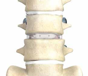
23 Based on surgeon preference, tamps, straight and footed, can be used to gently tamp the implant to its final position (Fig. 60). The Straight Tamp is designed to engage the rail for posterior adjustments (Fig. 58). The Footed Tamp is designed for midline adjustments (Fig. 59). Straight Tamp Figure 58 Footed Tamp Figure 59 Figure 60 There are three tantalum markers embedded within the PEEK material to help visually confirm its position under fluoroscopy (Fig. 61). A 4mm tantalum marker is positioned as the leading marker towards the nose of the implant. This marker is 6.8mm from the nose of the implant. A 2.5mm tantalum marker is positioned anteriorly, and is 2.2mm from the most anterior aspect of the implant. 2.2mm A 3mm tantalum marker is positioned on the trailing end, and is 6.9mm from the back rail of the implant. Figure mm 6.9mm 23

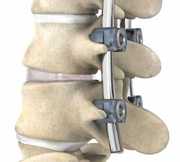
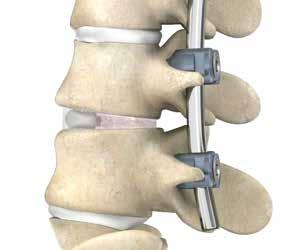
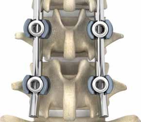
24 Step 10: Placement of Bone Graft Autogenous bone graft may be placed lateral, ventral, and/or dorsal to the implanted AVS Navigator Implant. INTRAOPERATIVE RESCUE If the surgeon chooses to realign or remove the implant prior to releasing the implant, and the implant is still engaged with the inserter, turn the locking dial clockwise to tighten back onto the implant. The implant may then be removed by using the Slaphammer to reverse impact the implant out of the disc space (Fig. 62). If the implant is disengaged from the inserter, the inserter should not be reattached to the implant for rescue. In this scenario, a blunt nerve hook may be used to remove the implant. Figure 62 Step 11: Posterior Fusion As the interbody portion of the procedure is now complete, distraction can be released. If pedicle screws had not been inserted earlier in the procedure, they may be inserted at this point. Vertical rods are connected to the screws and gentle compression is applied between the L4 and L5 screws bilaterally. This facilitates restoration of segmental lordosis and compression of the AVS Navigator Implant and bone graft. Apply appropriate final torque tightening to all screws. The remaining bone graft may be placed in the decorticated right L4-L5 facet to promote fusion. Intraoperative radiographs should be performed to confirm satisfactory position of the AVS Navigator Implant, pedicle screws, and bone graft (Fig. 63). Step 12: Closure Figure Check the left L4-L5 foramen and TLIF site for any bone fragments or extraneous soft tissue. Once satisfactory decompression of the exiting and traversing nerve roots is confirmed, the wound should be closed.
25 25


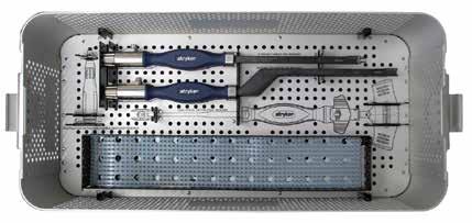
26 Top Insert Middle Insert Bottom Insert 26


27 Dynamic Distractor Container Top Insert Bottom Insert 27
28 Instruments Reference # Instrument Description Straight Inserter Bayoneted Inserter mm Trial, 0 Lordosis mm Trial, 0 Lordosis mm Trial, 0 Lordosis mm Trial, 0 Lordosis mm Trial, 0 Lordosis mm Trial, 0 Lordosis mm Trial, 0 Lordosis mm Trial, 0 Lordosis mm Trial, 0 Lordosis mm Trial, 0 Lordosis Reliance T-Handle Assembly Graft Block 26mm Assembly Graft Block 31mm Impactor Dynamic Distractor Extension Handle Reliance LITE Slaphammer Footed Tamp Straight Tamp Container Dynamic Distractor Container 28
29 Implants Reference # Implant Description mm x 26mm x 0 AVS Navigator Implant mm x 26mm x 0 AVS Navigator Implant mm x 26mm x 0 AVS Navigator Implant mm x 26mm x 0 AVS Navigator Implant mm x 26mm x 0 AVS Navigator Implant mm x 26mm x 0 AVS Navigator Implant mm x 26mm x 0 AVS Navigator Implant mm x 26mm x 0 AVS Navigator Implant mm x 26mm x 0 AVS Navigator Implant mm x 26mm x 0 AVS Navigator Implant mm x 26mm x 4 AVS Navigator Implant mm x 26mm x 4 AVS Navigator Implant mm x 26mm x 4 AVS Navigator Implant mm x 26mm x 4 AVS Navigator Implant mm x 26mm x 4 AVS Navigator Implant mm x 26mm x 4 AVS Navigator Implant mm x 26mm x 4 AVS Navigator Implant mm x 26mm x 4 AVS Navigator Implant mm x 26mm x 4 AVS Navigator Implant mm x 26mm x 4 AVS Navigator Implant 29
30 Implants Reference # Implant Description mm x 31mm x 0 AVS Navigator Implant mm x 31mm x 0 AVS Navigator Implant mm x 31mm x 0 AVS Navigator Implant mm x 31mm x 0 AVS Navigator Implant mm x 31mm x 0 AVS Navigator Implant mm x 31mm x 0 AVS Navigator Implant mm x 31mm x 0 AVS Navigator Implant mm x 31mm x 0 AVS Navigator Implant mm x 31mm x 0 AVS Navigator Implant mm x 31mm x 0 AVS Navigator Implant mm x 31mm x 4 AVS Navigator Implant mm x 31mm x 4 AVS Navigator Implant mm x 31mm x 4 AVS Navigator Implant mm x 31mm x 4 AVS Navigator Implant mm x 31mm x 4 AVS Navigator Implant mm x 31mm x 4 AVS Navigator Implant mm x 31mm x 4 AVS Navigator Implant mm x 31mm x 4 AVS Navigator Implant mm x 31mm x 4 AVS Navigator Implant mm x 31mm x 4 AVS Navigator Implant 30
31 IMPORTANT PRODUCT INFORMATION FOR STRYKER SPINE AVS NAVIGATOR PEEK SPACERS DESCRIPTION The AVS Navigator PEEK Spacers are intended for use as interbody fusion devices. They are offered in a variety of lengths, heights and lordotic angles. The hollow implant has serrations on the top and bottom for fixation. Radiopaque markers have been embedded within the implant to help allow for visualization in radiographic images. MATERIAL All components of all AVS PEEK Spacers systems are manufactured out of the following materials: Implant: Polyetheretherketone (PEEK) (ASTM F2026) Radiopaque markers: Tantalum (ASTM F560) INDICATIONS The Stryker Spine AVS Navigator PEEK Spacers are intervertebral body fusion devices indicated for use with autograft and/ or allogenic bone graft comprised of cancellous and/or corticocancellous bone graft when the subject device is used as an adjunct to fusion in patients with degenerative disc disease (DDD) at one level or two contiguous levels from L2 to S1. DDD is defined as back pain of discogenic origin with degeneration of the disc confirmed by history and radiographic studies. The DDD patients may also have up to Grade I spondylolisthesis at the involved level(s). These patients should be skeletally mature and have six months of nonoperative therapy. Additionally, the AVS Navigator PEEK Spacers can be used as an adjunct to fusion in patients diagnosed with degenerative scoliosis. The AVS Navigator PEEK Spacers are to be implanted via a posterior or posterolateral approach. The AVS Navigator PEEK Spacers are intended to be used with supplemental fixation systems that have been cleared for use in the lumbosacral spine. GENERAL CONDITIONS OF USE The implantation of intervertebral body fusion devices must be performed only by experienced spinal surgeons having undergone the necessary specific training in the use of such systems because this is a technically demanding procedure presenting a risk of serious injury to the patient. The information contained in the Package Insert is necessary but not sufficient for the use of this device. This information is in no sense intended as a substitute for the professional judgment, skill and experience of the surgeon in careful patient selection, preoperative planning and device selection, knowledge of the anatomy and biomechanics of the spine, understanding of the materials and the mechanical characteristics of the implants used, training and skill in spinal surgery and the use of associated instruments for implantation, securing the patient s cooperation in following an appropriately defined post-operative management program and conducting scheduled post-operative follow-up examinations. CAUTION Federal (USA) law restricts this device to sale by or on the order of a physician (or properly licensed practitioner) with appropriate training or experience. Based on the fatigue testing results, the physician/surgeon must consider the levels of implantation, patient weight, patient activity level, other patient conditions, etc. which may impact on the performance of the intervertebral body fusion device. The implantation of the intervertebral body fusion device must be performed only by experienced spinal surgeons with specific training in the use of this device because this is a technically demanding procedure presenting a risk of serious injury to the patient. Potential risks identified with the use of this intervertebral body fusion device, which may require additional surgery, include: device component fracture, loss of fixation, pseudoarthrosis (i.e. non-union), fracture of the vertebrae, neurological injury, and vascular or visceral injury. Specialized instruments are provided by STRYKER Spine and must be used to assure accurate implantation of the intervertebral body fusion device. While rare, intraoperative fracture or breakage of instruments can occur, instruments, which have experienced extensive use or extensive force, are more susceptible to fracture depending on the operative precaution, number of procedures, and disposal attention. Instruments must be examined for wear or damage prior to surgery. Instruments for implantation of the AVS PEEK Spacers are provided non-sterile and must be sterilized prior to use. The components of the system should not be used with components of any other system or manufacturer. Any such use will negate the responsibility of Stryker Spine for the performance of the resulting mixed component implant. The AVS PEEK Spacers have not been evaluated for safety and compatibility in the MR environment. The AVS PEEK Spacers have not been tested for heating or migration in the MR environment. INFECTION Transient bacteremia can occur in daily life. Dental manipulation, endoscopic examination and other minor surgical procedures have been associated with transient bacteremia. To help prevent infection at the implant site, it may be advisable to use antibiotic prophylaxis before and after such procedures. INSTRUMENTS Instruments are provided by STRYKER Spine and must be used to assure accurate implantation of the device. While rare, intraoperative fracture or breakage of instruments can occur. Instruments which have experienced extensive use or extensive force are more susceptible to fracture depending on the operative precaution, number of procedures, disposal attention. Instruments must be examined for wear or damage prior to surgery. REUSE Never reuse or re-implant spinal surgical implants. These could become contaminated resulting in infection. In addition, even though the device appears undamaged, it may have small defects which could compromise structural integrity reducing its service life and/or leading to patient injury. Surgeons must verify that the instruments are in good condition and operating order prior to use during surgery. HANDLING Correct handling of the implant is extremely important. The operating surgeon must avoid notching or scratching the device. ALLERGY AND HYPERSENSITIVITY TO FOREIGN BODIES When hypersensitivity is suspected or proven, it is highly recommended that the tolerance of the skin to the materials that make up the implants be checked before they are implanted. CONTRA-INDICATIONS Contraindications may be relative or absolute. The choice of a particular device must be carefully weighed against the patient s overall evaluation. Circumstances listed below may reduce the chances of a successful outcome: The AVS PEEK Spacers should not be implanted in patients with an active infection at the operative site. 31
32 The AVS PEEK Spacers are not intended for use except as indicated. Marked local inflammation. Any abnormality present which affects the normal process of bone remodeling including, but not limited to, severe osteoporosis involving the spine, bone absorption, osteopenia, primary or metastatic tumors involving the spine, active infection at the site or certain metabolic disorders affecting osteogenesis. Any mental or neuromuscular disorder which would create an unacceptable risk of fixation failure or complications in postoperative care. Open wounds. Pregnancy. Inadequate tissue coverage over the operative site. Any neuromuscular deficit which places an unsafe load level on the device during the healing period. Obesity. An overweight or obese patient can produce loads on the spinal system which can lead to failure of the fixation of the device or to failure of the device itself. Obesity is defined according to the W.H.O. standards. A condition of senility, mental illness, or substance abuse. These conditions, among others, may cause the patient to ignore certain necessary limitations and precautions in the use of the implant, leading to failure or other complications. Foreign body sensitivity. Where material sensitivity is suspected, appropriate tests must be made prior to material selection or implantation. Other medical or surgical condition which would preclude the potential benefit of spinal implant surgery, such as the presence of tumors, congenital abnormalities, elevation of sedimentation rate unexplained by other diseases, elevation of white blood cell count (WBC), or marked left shift in the WBC differential count. Prior fusion at the levels to be treated These contra-indications can be relative or absolute and must be taken into account by the physician when making his decision. The above list is not exhaustive. Surgeons must discuss the relative contraindications with the patients. INFORMATION FOR PATIENTS The surgeon must discuss all physical and psychological limitations inherent to the use of the device with the patient. This includes the rehabilitation regimen, physical therapy, and wearing an appropriate orthosis as prescribed by the physician. Particular discussion should be directed to the issues of premature weight bearing, activity levels, and the necessity for periodic medical follow-up. The surgeon must warn the patient of the surgical risks and make them aware of possible adverse effects. The surgeon must warn the patient that the device cannot and does not replicate the flexibility, strength, reliability or durability of normal healthy bone, that the implant can break or become damaged as a result of strenuous activity or trauma, and that the device may need to be replaced in the future. If the patient is involved in an occupation or activity which applies inordinate stress upon the implant (e.g., substantial walking, running, lifting, or muscle strain) the surgeon must advice the patient that resultant forces can cause failure of the device. Patients who smoke have been shown to have an increased incidence of nonunions. Such patients should be advised of this fact and warned of the potential consequences. For diseased patients with degenerative disease, the progression of degenerative disease may be so advanced at the time of implantation that it may substantially decrease the expected useful life of the appliance. In such cases, orthopaedic devices may be considered only as a delaying technique or to provide temporary relief. Patients with previous spinal surgery at the level(s) to be treated may have different clinical outcomes compared to those without a previous surgery. PRE-OPERATIVE PRECAUTIONS The surgical indication and the choice of implants must take into account certain important criteria such as: Patients involved in an occupation or activity that applies excessive loading upon the implant (e.g., substantial walking, running, lifting, or muscle strain) may be at increased risk for failure of the fusion and/or the device. Surgeons must instruct patients in detail about the limitations of the implants, including, but not limited to, the impact of excessive loading through patient weight or activity, and be taught to govern their activities accordingly. The procedure will not restore function to the level expected with a normal, healthy spine, and the patient should not have unrealistic functional expectations. A condition of senility, mental illness, chemical dependence or alcoholism. These conditions among others may cause the patients to ignore certain necessary limitations and precautions in the use of the implant, leading to failure and other complications. Foreign body sensitivity. Where material sensitivity is suspected appropriate tests should be made prior to material implantation. Surgeons must advise patients who smoke have been shown to have an increased incidence of nonunions. Such patients must be advised of this fact and warned of the potential consequences. Care must be taken to protect the components from being marred, nicked, or notched as a result of contact with metal or abrasive objects. THE CHOICE OF IMPLANTS The choice of proper shape, size and design of the implant for each patient is crucial to the success of the surgery. The surgeon is responsible for this choice, which depends on each patient. Patients who are overweight may add additional stresses and strains on the device which can lead to implant fatigue and/or lead to deformation or failure of the implants. The size and shape of the bone structures determine the size, shape and type of the implants. Once implanted, the implants are subjected to stresses and strains. These repeated stresses on the implants must be taken into consideration by the surgeon at the time of the choice of the implant, during implantation as well as in the post-operative follow-up period. Indeed, the stresses and strains on the implants may cause fatigue, fracture or deformation of the implants, before the bone graft has become completely consolidated. This may result in further side effects or necessitate the early removal of the osteosynthesis device. INTRA-OPERATIVE PRECAUTIONS The insertion of the implants must be carried out using instruments designed and provided for this purpose and in accordance with the specific implantation instructions for each implant. Those detailed instructions are provided in the surgical technique brochure supplied by STRYKER Spine. Discard all damaged or mishandled implants. Never reuse an implant, even though it may appear undamaged. PATIENT CARE FOLLOWING TREATMENT Prior to adequate maturation of the fusion mass, implanted spinal instrumentation may need additional help to accommodate full load bearing. External support may be recommended by the physician from two to four months postoperatively or until x-rays or other procedures confirm adequate maturation of the fusion mass; external immobilization by bracing or casting be employed. Surgeons must instruct patients regarding appropriate and restricted 32
33 activities during consolidation and maturation for the fusion mass in order to prevent placing excessive stress on the implants which may lead to fixation or implant failure and accompanying clinical problems. Surgeons must instruct patients to report any unusual changes of the operative site to his/her physician. The physician must closely monitor the patient if a change at the site has been detected. ADVERSE EFFECTS Include but are not limited to: Late bone fusion or no visible fusion mass and pseudarthrosis; While the expected life of spinal implant components is difficult to estimate, it is finite. These components are made of foreign materials which are placed within the body for the potential fusion of the spine and reduction of pain. However, due to the many biological, mechanical and physicochemical factors which affect these devices but cannot be evaluated in vivo, the components cannot be expected to indefinitely withstand the activity level and loads of normal healthy bone; Superficial or deep-set infection and inflammatory phenomena; Allergic reactions to the implanted materials, although uncommon, can occur; Decrease in bone density due to stress shielding; Dural leak requiring surgical repair; Peripheral neuropathies, nerve damage, heterotopic bone formation and neurovascular compromise, including paralysis, loss of bowel or bladder function, or foot-drop may occur. Cessation of growth of the fused portion of the spine; Loss of proper spinal curvature, correction, height and/or reduction; Delayed Union or Nonunion: Internal fixation appliances are load sharing devices which are used to obtain alignment until normal healing occurs. In the event that healing is delayed, does not occur, or failure to immobilize the delayed/ nonunion results, the implant will be subject to excessive and repeated stresses which can eventually cause loosening, bending or fatigue fracture. The degree or success of union, loads produced by weight bearing, and activity levels will, among other conditions, dictate the longevity of the implant. If a nonunion develops or if the implants loosen, bend or break, the device(s) must be revised or removed immediately before serious injury occurs; Neurological and spinal dura mater lesions from surgical trauma; Early loosening may result from inadequate initial fixation, latent infection, premature loading of the device or trauma. Late loosening may result from trauma, infection, biological complications or mechanical problems, with the subsequent possibility of bone erosion, or pain. Serious complications may occur with any spinal surgery. These complications include, but are not limited to, genitourinary disorders; gastrointestinal disorders; vascular disorders, including thrombus; bronchopulmonary disorders, including emboli; bursitis, hemorrhage, myocardial infarction, infection, paralysis or death. Inappropriate or improper surgical placement of this device may cause distraction or stress shielding of the graft or fusion mass. This may contribute to failure of an adequate fusion mass to form. Intraoperative fissure, fracture, or perforation of the spine can occur due to implantation of the components. Postoperative fracture of bone graft or the intervertebral body above or below the level of surgery can occur due to trauma, the presence of defects, or poor bone stock. Adverse effects may necessitate reoperation or revision. The surgeon must warn the patient of these adverse effects as deemed necessary. REMOVAL If fusion / bone graft growth occurs, the device will be deeply integrated into the bony tissues. As a result, the AVS PEEK Spacers are not intended to be removed unless the management of a complication or adverse event requires the removal. Any decision by a physician to remove the device should take into consideration such factors as: The risk to the patient of the additional surgical procedure as well as the difficulty of removal. Migration of the implant, with subsequent pain and/or neurological, articular or soft tissue lesions Pain or abnormal sensations due to the presence of the implants Infection or inflammatory reactions Reduction in bone density due to the different distribution of mechanical and physiological stresses and strains PACKAGING The implants are single use devices, provided non-sterile, and delivered in individual packages. The typical packaging used is clear plastic tubes and polyethylene bags. The packages must be intact at the time of receipt. Implants must be removed entirely from their packaging prior to sterilization. The implants may also be supplied as a complete set: implants and instruments are arranged on trays and placed in specially designed storage boxes FURTHER INFORMATION A surgical technique brochure is available on request through your STRYKER representative or directly from STRYKER Spine. Users with brochures that are over two years old at the time of surgery are advised to ask for an updated version. COMPLAINTS Any health professional having a complaint or grounds for dissatisfaction relating to the identity, quality, durability, reliability, safety, effectiveness or performance of a device should notify STRYKER Spine or its representative. Moreover, if a device has malfunctioned, or is suspected of having malfunctioned, STRYKER Spine or its representative must be advised immediately. If a STRYKER Spine product has ever worked improperly and could have caused or contributed to the death of or serious injury to a patient, the distributor or STRYKER Spine must be informed as soon as possible by telephone, fax or in writing. For all complaints, please include the name and reference along with the batch number of the component(s), your name and address and an exhaustive description of the event to help STRYKER Spine understand the causes of the complaint. For further information regarding services, please contact: STRYKER Spine 2 Pearl Court, Allendale, NJ USA Tel:
34 AVS NAVIGATOR INSERTER INSTRUMENTATION INSTRUCTIONS FOR USE STRYKER SPINE AVS NAVIGATOR INSERTERS NON STERILE PRODUCT INSTRUCTIONS FOR USE PACKAGE INSERT Description / Material Composition Surgical instruments supplied by STRYKER Spine are manual medical tools designed solely for use in the fitting of STRYKER Spine implants. They are made of different materials including stainless steel, aluminum, titanium and plastics (silicone, acetal, etc) that comply with the standards applicable to their specific material composition. However these materials are not implantable. STRYKER Spine instruments do not contain natural rubber (such as: natural rubber latex, dry natural rubber, and synthetic latex or synthetic rubber that contains natural rubber in its formulation). Intended Use The AVS Navigator Inserter instruments (references # and # ) are intended to be used exclusively with the AVS Navigator PEEK Spacers. STRYKER Spine instruments must be used in the manner described in the Surgical Techniques brochures provided by STRYKER Spine. Unless labelled for single use, this instrument may be re-used. Prior to using the instruments, the surgeon shall have given careful consideration to all aspects of the surgical intervention as well as to the limits of the instrumentation. Recommendations for use are provided in the Surgical Technique brochures available from STRYKER Spine representatives. Under no circumstances may STRYKER Spine instruments be used to fit components from other manufacturers, if STRYKER Spine instruments are used in such cases the company shall not be liable for the operation of the resulting unit. Likewise, STRYKER Spine implants may only be implanted with the appropriate instruments supplied by STRYKER Spine. STRYKER Spine shall not be liable for implants implanted using other manufacturer s instruments. Reuse Instruments labelled as single use shall not be reused. While a single-use instrument may appear undamaged, the instrument may have acquired contaminants that compromise sterility and/or blemishes, nicks or latent compromise of its integrity. Potential Adverse Effects Incorrect maintenance, cleaning or handling may render the instruments unsuitable for their intended use, cause corrosion, dismantling, distortion and/or breakage or cause injury to the patient or operating staff. Below is a list, albeit not exhaustive, of potential complications: Neurological lesion, paralysis, pain, lesion of the soft tissues, the visceral organs or the joints, in the event of incorrect use or breakage of the instruments. Infection, if the instruments are not properly cleaned and sterilized. Dural leaks, compression of vessels, damage to nerves or nearby organs as a result of slippage or poor positioning of a faulty instrument. Damage caused by the involuntary releasing of the springs of certain instruments. Damage caused by the instruments used to bend or cut in-situ due to excessive forces occurring when they are used. Cutting the gloves or the skin of surgical staff. Tissue lesions on the patient or surgical staff and/or an increase in operating time as a result of having to dissemble the instruments during surgery. Crack, fracture or involuntary perforation of the bone. As a result of the mechanical features required, most of the instruments are made of non implantable materials. In the event an instrument breaks, no fragment must remain in the patient as this could cause post-operative complications such as allergies, infections, or complications of a biological nature associated with the release of metal components, possibly requiring further intervention. Packaging STRYKER Spine instruments may be supplied either sterile or non-sterile in instrument containers or individual packaging. Instruments sold sterile are always presented in individual packaging and will be clearly labelled as sterile on the package label. The sterilization method applied is indicated on the product label. The sterile instrument packaging must be intact at the time of receipt and the integrity of the packaging shall be checked prior to use. The containers and the packaging of the instruments must be intact when received. The packaging materials must be removed prior to sterilization. Examination Prior to Use For instruments sold sterile: Before utilization, it is necessary to verify the sterility expiration date, which is indicated as the use by date. Stryker Spine cannot be held responsible for use of its products after their expiration date. Pre-sterilized instruments must not be allowed to come into contact with any disinfectant product or solution. It is recommended to verify the integrity of the original package before use. Sterility is ensured only if there is no trace of damage to the packaging. In case of damage to the packaging, or after opening of the packaging, re-sterilization of the instrument is strictly forbidden, regardless of the method that might be employed. Instruments should be visually examined for damage by doctors and staff in operating centers prior to and after surgery. For instruments designed for single use (sold non-sterile): It is recommended to verify the integrity of the instrument and original package before use. Instruments should be visually examined for damage by doctors and staff in operating centers prior to surgery. For instruments designed for re-use: The life of the instrument depends on the number of times they are used as well as the precautions taken in handling, cleaning and storage. Great care must be taken of the instruments to ensure that they remain in good working order. Instruments should be examined for wear or damage by doctors and staff in operating centers prior to surgery. The examination shall include a visual and functional inspection of the working surfaces, articulation points, and springs. It should also include verifying all welded connections, that all components are present, and the cleanliness of the orifices and cavities, as well as the absence of any cracks, distortion, impact, corrosion or other change. For instruments with articulations, lubrication may be necessary. Using a silicone lubricating cream is recommended. Special attention should be paid to the clamping keys, especially to the hexagonal shank bits. The latter must not be blunt as this could compromise the clamping of the fittings and lead to a risk of detaching. 34
QIN4432TRICREV01. IMPORTANT PRODUCT INFORMATION FOR TRITANIUM C Cervical Cage. Version 1 1 STERILE PRODUCT
 IMPORTANT PRODUCT INFORMATION FOR TRITANIUM C Cervical Cage STERILE PRODUCT DESCRIPTION The Stryker Spine Tritanium C Anterior Cervical Cage is a hollow, ring shaped titanium alloy (Ti-6Al- 4V) interbody
Features & Benefits. 1) Wide Bone Graft Space. Anterior Margin 3mm Posterior Margin 1.5mm. Marker Margin
 Wide Bone Graft Space. Anterior Margin 3mm Posterior Margin 1.5mm. Marker Margin") ALIF Cage System LnK ALIF Cage System The LnK ALIF Cage can make solid inter-body fusion with optimized anatomical position. Broad bone graft area also makes perfect fusion. It can be used with additional
ALIF Cage System LnK ALIF Cage System The LnK ALIF Cage can make solid inter-body fusion with optimized anatomical position. Broad bone graft area also makes perfect fusion. It can be used with additional
PLIF/TPLIF Cage System
 PLIF/TPLIF Cage System LnK Lumbar Interbody Fusion Cage System LnK PLIF / T-PLIF Cage The LnK Interbody Fixation System implants are interbody fusion devices intended for use as an aid in spinal fixation.
nvt Transforaminal Lumbar Interbody Fusion System
 nvt Transforaminal Lumbar Interbody Fusion System 1 IMPORTANT INFORMATION FOR PHYSICIANS, SURGEONS, AND/OR STAFF The nv a, nv p, and nv t are an intervertebral body fusion device used in the lumbar spine
nvp Posterior Lumbar Interbody Fusion System
 nvp Posterior Lumbar Interbody Fusion System 1 IMPORTANT INFORMATION FOR PHYSICIANS, SURGEONS, AND/OR STAFF The nv a, nv p, and nv t are an intervertebral body fusion device used in the lumbar spine following
nva Anterior Lumbar Interbody Fusion System
 nva Anterior Lumbar Interbody Fusion System 1 IMPORTANT INFORMATION FOR PHYSICIANS, SURGEONS, AND/OR STAFF The nv a, nv p, and nv t are an intervertebral body fusion device used in the lumbar spine following
Alamo T Transforaminal Lumbar Interbody System Surgical Technique
 Transforaminal Lumbar Interbody System Surgical Technique Table of Contents Indications and Device Description.............. 1 Alamo T Implant Features and Instruments...........2 Surgical Technique......................
IBD PEEK C. Anterior Cervical Spacer System. Surgical Technique
 IBD PEEK C Anterior Cervical Spacer System Surgical Technique Table of Contents Introduction.... 3 Step 1: Exposure... 3 Step 2: Discectomy... 4 Step 3: Endplate Preparation... 5 Step 4: Trialing... 6
Posterior Lumbar Interbody Fusion System
 Px Posterior Lumbar Interbody Fusion System Px PEEK INTERBODY FUSION SYSTEM INDICATIONS FOR USE The Innovasis Px PEEK IBF System is an intervertebral body fusion device for use in patients with degenerative
Alamo C. Cervical Interbody System Surgical Technique. An Alliance Partners Company
 Cervical Interbody System Surgical Technique Table of Contents Indications for Use................................1 Device Description............................... 1 Alamo C Instruments..............................
AVS TL PEEK Spacer System TLIF Surgical Technique. Friday, March 28, 2014 Chicago, IL
 AVS TL PEEK Spacer System TLIF Surgical Technique Friday, March 28, 2014 Chicago, IL Transforaminal Lumbar Interbody Fusion Technique Acknowledgements Stryker Spine wishes to thank the following physicians
Royal Oak IBFD System Surgical Technique Posterior Lumbar Interbody Fusion (PLIF)
") Royal Oak IBFD System Surgical Technique Posterior Lumbar Interbody Fusion (PLIF) Preoperative Planning Preoperative planning is necessary for the correct selection of lumbar interbody fusion devices.
Royal Oak IBFD System Surgical Technique Posterior Lumbar Interbody Fusion (PLIF) Preoperative Planning Preoperative planning is necessary for the correct selection of lumbar interbody fusion devices.
INTELLIGENT SPINAL SYSTEM
 INTELLIGENT SPINAL SYSTEM I. Introduction II. Product Specification III. Surgical Technique IV. Ordering Information V. IFU for Lospa IS SPINAL SYSTEM The LOSPA IS spinal system consists of
OPERATIVE TECHNIQUE. CONSTRUX Mini PTC. Mini PTC Spacer System
 OPERATIVE TECHNIQUE CONSTRUX Mini PTC Mini PTC Spacer System TABLE OF CONTENTS Introduction 1 Operative Technique 2 Part Numbers 6 Indications For Use 7 INTRODUCTION 1 INTRODUCTION The CONSTRUX Mini PTC
TABLE OF CONTENTS. ShurFit Anterior Cervical Interbody Fusion (ACIF) System Overview 2. Implant Specifications 3. Instrument Features 4
 System Overview 2. Implant Specifications 3. Instrument Features 4") Surgical Technique TABLE OF CONTENTS ShurFit Anterior Cervical Interbody Fusion (ACIF) System Overview 2 Product Highlights 2 Indications 2 Implant Specifications 3 Instrument Features 4 Surgical Technique
Surgical Technique TABLE OF CONTENTS ShurFit Anterior Cervical Interbody Fusion (ACIF) System Overview 2 Product Highlights 2 Indications 2 Implant Specifications 3 Instrument Features 4 Surgical Technique
TM TM Surgical Technique
 TM TM Surgical Technique TABLE OF CONTENTS Reli SP Spinous Plating System Overview Device Description Implant Features Indications Instruments Access Instruments Preparation Instruments Insertion Instruments
EXACTECH SPINE. Operative Technique. Cervical Spacer System. Surgeon focused. Patient driven. TM
 EXACTECH SPINE Operative Technique Cervical Spacer System Surgeon focused. Patient driven. TM ACAPELLA ONE Acapella One Cervical Spacer System is an anterior cervical discectomy and fusion device with
A U X I L I A R Y C O N N E C T O R S Surgical Technique
 A U X I L I A R Y C O N N E C T O R S Surgical Technique AUXILIARY CONNECTORS ISSYS LP Auxiliary Connectors The ISSYS LP auxiliary connectors were designed to provide medial-lateral variability for the
Apache Cervical Interbody Fusion Device. Surgical Technique. Page of 13. LC-005 Rev F
 LC-005 Rev F Apache Cervical Interbody Fusion Device Page of 13 Surgical Technique INDICATIONS: When used as an intervertebral body fusion device, the Genesys Spine Interbody Fusion System is indicated
Cervical Spacer System surgical technique
 Blackhawk TM Cervical Spacer System surgical technique Blackhawk TM The BLACKHAWK Cervical Spacer System is designed to provide biomechanical stabilization as an adjunct to fusion. Spinal fixation should
Surgical Technique. Apache Posterior Lumbar Interbody Fusion Apache Transforaminal Lumbar Interbody Fusion
 Surgical Technique Apache Posterior Lumbar Interbody Fusion Apache Transforaminal Lumbar Interbody Fusion 2 Table of Contents Page Preoperative Planning 4 Patient Positioning 5 Disc Exposure 5 Disc and
C-THRU Anterior Spinal System
 C-THRU Anterior Spinal System Surgical Technique Manufactured From Contents Introduction... Page 1 Design Features... Page 2 Instruments... Page 3 Surgical Technique... Page 4 Product Information... Page
product overview Implant heights range from 8mm-20mm in 2mm increments, with two lordocic angle options of 6 and 12.
 ETHOS A-Spacer PEEK System Surgical Technique Guide Synchronizing Medical Innovation with Global Markets product overview The SyncMedical Ethos PEEK IBF System is an intervertebral body fusion device for
SURGICAL TECHNIQUE MANUAL. InterFuse T
 1 CONTENTS InterFuse T Product Description 3 Indications for Use 3 X-Ray Marker Locations 4 Product Specifications 4 Instrument Set 5 Step 1 Preoperative Planning 8 Patient Positioning 8 Step 2 Disc Removal
Surgical Technique. Apache Anterior Lumbar Interbody Fusion
 Surgical Technique Apache Anterior Lumbar Interbody Fusion 2 Table of Contents Page Preoperative Planning 4 Patient Positioning 4 Disc and Endplate Preparation 4 Distraction/Size Selection 5 Implantation
CROSS -FUSE P E E K V B R / I B F SYST E M
 S U R G I C A L T E C H N I Q U E CROSS -FUSE P E E K V B R / I B F SYST E M S U R G I C A L S Y S T E M O V E R V I E W 2 CROSS-FUSE P E E K V B R / I B F S Y S T E M S U R G I C A L T E C H N I Q U E
PILLAR AL. Anterior Lumbar Interbody Fusion (ALIF) and Partial Vertebral Body Replacement (pvbr) PEEK Spacer System OPERATIVE TECHNIQUE
 and Partial Vertebral Body Replacement (pvbr) PEEK Spacer System OPERATIVE TECHNIQUE") PILLAR AL PEEK Spacer System Anterior Lumbar Interbody Fusion (ALIF) and Partial Vertebral Body Replacement (pvbr) OPERATIVE TECHNIQUE Table of Contents 1 INTRODUCTION 2 PRE-OPERATIVE TECHNIQUE 3 OPERATIVE
PILLAR AL PEEK Spacer System Anterior Lumbar Interbody Fusion (ALIF) and Partial Vertebral Body Replacement (pvbr) OPERATIVE TECHNIQUE Table of Contents 1 INTRODUCTION 2 PRE-OPERATIVE TECHNIQUE 3 OPERATIVE
HawkeyeTM Peek. surgical technique
 HawkeyeTM Peek surgical technique Introduction The ChoiceSpine HAWKEYE Vertebral Body Replacement (VBR) System is intended for use in the thoracolumbar spine (T1 - L5) to replace a collapsed, damaged,
VTI INTERFUSE T SURGICAL TECHNIQUE FORWARD THINKING FOR THE BACK. 1/20
 VTI INTERFUSE T SURGICAL TECHNIQUE FORWARD THINKING FOR THE BACK. 1/20 CONTENTS InterFuse T Product Description Indications for Use X-Ray Marker Locations Product Specifications Instrument Set 3 4 5 STEP
Tritanium PL Posterior Lumbar Cage
 Tritanium PL Posterior Lumbar Cage Table of contents Tritanium technology overview...3 Description...5 Step 1: Exposure open approach...6 Step 2: Preparation of facet joints...7 Step 3: Insertion site
VTI INTERLINK PEDICLE SCREW SYSTEM
 VTI INTERLINK PEDICLE SCREW SYSTEM SURGICAL TECHNIQUE FORWARD THINKING FOR THE BACK. DEVICE DESCRIPTION The VTI InterLink Pedicle Screw System is comprised of polyaxial pedicle screws in various diameters
T.L.I.F. Surgical Technique. Featuring the T.L.I.F. SG Instruments, VG2 PLIF Allograft, and the MONARCH Spine System.
 Surgical Technique T.L.I.F. Transforaminal Lumbar Interbody Fusion Featuring the T.L.I.F. SG Instruments, VG2 PLIF Allograft, and the MONARCH Spine System. CONSULTING SURGEON Todd Albert, M.D. Rothman
Tritanium PL Posterior Lumbar Cage
 Tritanium PL Posterior Lumbar Cage Table of contents Tritanium technology overview...3 Description...5 Step 1: Exposure open approach...6 Step 2: Preparation of facet joints...7 Step 3: Insertion site
Advantage ALIF. Keith Shevlin Managing Director
 Advantage ALIF Unit 10, 9-11 Myrtle Street, Crows Nest NSW 2065 Keith Shevlin Managing Director keithshevlin@precisionsurgical.com.au Advantage ALIF Introduction & Indications for Use 1 Surgical Technique
Thoracolumbar Solutions. Zyston Curve. Interbody Spacer System. Surgical Technique Guide
 Thoracolumbar Solutions Zyston Curve Interbody Spacer System Surgical Technique Guide 2 Zyston Curve Interbody Spacer System Surgical Technique Guide The Zyston Curve Interbody System is designed to optimize
EIT TLIF Cage. For Natural Bone Ingrowth with EIT Cellular Titanium
 EIT TLIF Cage For Natural Bone Ingrowth with EIT Cellular Titanium EIT TLIF Cage Surgical Technique EIT Cellular Titanium provides active fusion area» ~ 80% porosity» ~ 650 µm diamond pore size» open interconnected
VTI INTERFUSE S SURGICAL TECHNIQUE FORWARD THINKING FOR THE BACK.
 VTI INTERFUSE S SURGICAL TECHNIQUE FORWARD THINKING FOR THE BACK. CONTENTS InterFuse S Product Description Indications for Use X-Ray Marker Locations and Product Specifications Instrument Set 3 4 5-7 STEP
TABLE OF CONTENTS. Vault C Anterior Cervical Discectomy 2 and Fusion (ACDF) System Overview. Implants 3. Instruments 5. Surgical Technique 10
 System Overview. Implants 3. Instruments 5. Surgical Technique 10") Surgical Technique TABLE OF CONTENTS Vault C Anterior Cervical Discectomy 2 and Fusion (ACDF) System Overview Indications 2 Implants 3 Instruments 5 Surgical Technique 10 1. Preoperative planning 10 2.
Surgical Technique TABLE OF CONTENTS Vault C Anterior Cervical Discectomy 2 and Fusion (ACDF) System Overview Indications 2 Implants 3 Instruments 5 Surgical Technique 10 1. Preoperative planning 10 2.
Imola Lateral IBF System Surgical Technique
 Imola Lateral IBF System Surgical Technique IMOLA CIRCUIT TABLE OF CONTENTS Design Rationale Instructions for Use Surgical Technique 1. Table Mounting 2. Surgical Planning & Targeting 3. Access and Preparation
PATHWAY PLIF and PATHWAY TLIF. SPINAL ELEMENTS PATHWAY PLIF And PATHWAY TLIF PATHWAY
 PATHWAY PLIF and PATHWAY TLIF SPINAL ELEMENTS PATHWAY PLIF And PATHWAY TLIF PATHWAY CAUTION: Federal law (U.S.A.) restricts this device to sale by or on the order of a licensed physician. NON STERILE PRODUCT
Ardis. Surgical Technique. Interbody System. Solutions by the people of Zimmer Spine. zimmerspine.com
 Ardis Interbody System Surgical Technique Solutions by the people of Zimmer Spine. zimmerspine.com A more advanced interbody solution. From the people of Zimmer Spine. The easily inserted Ardis Interbody
Pinit Plate Small Bone Fusion System Bone Plate & Screw System
 Pinit Plate Small Bone Fusion System Bone Plate & Screw System Description The Pinit Plate Small Bone Fusion System consists of 2-hole bone plates made available in three length options and two thickness
ACP1 CERVICAL PLATE SPINAL SYSTEM SURGICAL TECHNIQUE GUIDE II.
 I. ACP1 CERVICAL PLATE II. SPINAL SYSTEM SURGICAL TECHNIQUE GUIDE I. Introduction The Gold Standard Orthopaedics, LLC ACP1 Spinal System was designed with surgeons to incorporate strength, functionality,
UniVise Spinous Process Fixation Plate System. Surgical Technique. Simple, One-Piece Design Anatomically Shaped Plates Optimized Radial Spike Pattern
 UniVise Spinous Process Fixation Plate System Simple, One-Piece Design Anatomically Shaped Plates Optimized Radial Spike Pattern Table of Contents Device Description... 3 UniVise Key Design Features...
AVS Anchor -C Cervical Cage System Surgical Technique
 AVS Anchor -C Cervical Cage System Table of Contents System Overview.... 3 Implantation Technique.... 4 Implant Removal..................................................... 14 Implant Part Numbers....
Royal Oak Cervical Plate System
 Royal Oak Cervical Plate System Manufactured by Nexxt Spine, Inc. Royal Oak Cervical Plate System INTRODUCTION FEATURES AND BENEFITS Table of Contents SURGICAL TECHNIQUE Step 1. Patient Positioning Step
TraXis TLIF Interbody System
 TraXis TLIF Interbody System Surgical Technique Solutions by the people of Zimmer Spine. zimmerspine.com A TLIF that s ahead of the curve. From the people of Zimmer Spine. Minimally Invasive Surgery (MIS)
T.L.I.F. Transforaminal Lumbar Interbody Fusion
 T.L.I.F. Transforaminal Lumbar Interbody Fusion Cover Surgical Header Technique Sub Guide header Introduction (T.L.I.F. ) technique has gained wide acceptance Additionally, the T.L.I.F. procedure avoids
Solitaire Anterior Spinal System
 Surgical Technique Solitaire Anterior Spinal System Independent Stabilization for the Anterior Column Available in Titanium and Contents Introduction... Page 1 Design Features... Page 2 Instruments...
Veyron -C Anterior Cervical System Surgical Technique
 Veyron -C Anterior Cervical System Surgical Technique 2 Veyron-C Anterior Cervical System Surgical Technique Veyron-C Anterior Cervical System Surgical Technique Description, Indications & Contraindications...3
ACP. Anterior Cervical Plate System SURGICAL TECHNIQUE
 ACP Anterior Cervical Plate System SURGICAL TECHNIQUE ACP TABLE OF CONTENTS INTRODUCTION 4 INDICATIONS AND CONTRAINDICATIONS 5 WARNINGS AND PRECAUTIONS 6 IMPLANT DESCRIPTION 7 INSTRUMENTS 10 SURGICAL
STRYKER SPINE Spinal Fixation Systems XIA 3
 STRYKER SPINE Spinal Fixation Systems XIA 3 NON STERILE PRODUCT The STRYKER Spine Spinal Fixation Systems are made of devices for fixation of the non-cervical spine. They include smooth rods, screws, hooks,
Patient Information MIS LLIF. Lateral Lumbar Interbody Fusion Using Minimally Invasive Surgical Techniques
 Patient Information MIS LLIF Lateral Lumbar Interbody Fusion Using Minimally Invasive Surgical Techniques Table of Contents Anatomy of Spine...2 General Conditions of the Spine....4 What is Spondylolisthesis....5
Fusion Device. Surgical Technique. Cervical Interbody Fusion with Trabecular Metal Technology
 TM-S Fusion Device Surgical Technique Cervical Interbody Fusion with Trabecular Metal Technology 2 TM-S Fusion Device Surgical Technique Disclaimer This surgical technique is not intended for use in the
InFix. Anterior Lumbar Device. Surgical Technique Guide
 InFix Anterior Lumbar Device Surgical Technique Guide 2 InFix Anterior Lumbar Device Surgical Technique Guide InFix Anterior Lumbar System s modular design is intended to restore lordosis, disc height
Y o u r Id e a s En g i n e e r e d t o Li f e
 ISSYS LP Spinal Fixation System Surgical Guide Y o u r Id e a s En g i n e e r e d t o Li f e In t r o d u c t i o n ISSYS LP Sp i n a l Fixation System The foundation of the ISSYS LP Spinal Fixation System
L-VARLOCK. Posterior Lumbar Cage with adjustable lordosis. S urgical T echnique
 L-VARLOCK Posterior Lumbar Cage with adjustable lordosis S urgical T echnique Introduction Designed and manufactured by KISCO International, L-VARLOCK cages are made of titanium alloy Ti 6AI 4V (standards
Aero -C Anterior Cervical Interbody and Fixation System
 Aero -C Anterior Cervical Interbody and Fixation System Table of contents System overview.... 3 Implant overview.... 4 Step 1. Patient positioning and exposure.... 6 Step 2. Discectomy and endplate preparation...
Surgical Technique Manual
 InterFuse S Interbody Fusion System Surgical Technique Manual VERTEBRAL TECHNOLOGIES MS 4043-02 Rev. O Product Overview Introduction The VTI InterFuse S implant is an interbody fusion device that combines
OPERATIVE TECHNIQUE PTC PEEK FORZA. spacer system
 OPERATIVE TECHNIQUE PTC PEEK FORZA spacer system TABLE OF CONTENTS Introduction 1 Operative Technique 2 Instruments 12 FORZA PEEK Part Numbers 20 FORZA PTC Part Numbers 22 Modular Implant Inserter 24 Disassembly
Lapidus Arthrodesis System Instructions for Use
 Lapidus Arthrodesis System Instructions for Use Description The AlignMATE Lapidus Arthrodesis System consists of bone plates and bone screws (locking, non-locking and interfragmentary), which are intended
Thoracolumbar Solutions. Avenue T. TLIF Cage. with ertebridge PLATING TECHNOLOGY. Surgical Technique Guide
 Thoracolumbar Solutions Avenue T TLIF Cage with ertebridge PLATING TECHNOLOGY Surgical Technique Guide 2 Avenue T TLIF Cage Surgical Technique VerteBRIDGE Plating is the integrated fixation designed specifically
SECURIS SPINAL Fixation System Package Insert
 SECURIS SPINAL Fixation System Package Insert AMENDIA SECURIS SPINAL Fixation System CAUTION: Federal law (U.S.A.) restricts this device to sale by or on the order of a licensed physician. NON STERILE
Aesculap CeSpace TM PEEK and CeSpace TM XP Spinal Implant System Instructions for Use
 Aesculap CeSpace TM PEEK and CeSpace TM XP Spinal Implant System Instructions for Use Page 1 of 5 Indications for use: When used as a Vertebral Body Replacement Device: The CeSpace PEEK and CeSpace XP
O PE RATIV E TE C HN IQ U E. ProView. Expandable Retractor System U.S. EDITION
 O PE RATIV E TE C HN IQ U E ProView M I N I M A L A C C E S S P O R TA L ( M A P ) S Y S T E M Expandable Retractor System U.S. EDITION Table of Contents 1 INTRODUCTION 2 OPERATIVE TECHNIQUE 9 PART NUMBERS
Surgical Technique. TraXis. Precision. Transforaminal Lumbar Interbody Fusion Spacer. The Art & Science of Spine Surgery
 Surgical Technique Precision TraXis Transforaminal Lumbar Interbody Fusion Spacer The Art & Science of Spine Surgery Table of Contents Introduction 3 Indications 4 Key Instruments 5 Surgical Technique
Transforaminal Lumbar Interbody Fusion Cage (TLIF)
") Transforaminal Lumbar Interbody Fusion age (TLIF) 990100010 DOULE ENGINE MEDIL MTERIL O., LTD. No. 218 Houxiang Road, Haicang District, Xiamen 361022, P.R.hina Tel: +86 592 6087101 Fax: +86 592 6587078
Transforaminal Lumbar Interbody Fusion age (TLIF) 990100010 DOULE ENGINE MEDIL MTERIL O., LTD. No. 218 Houxiang Road, Haicang District, Xiamen 361022, P.R.hina Tel: +86 592 6087101 Fax: +86 592 6587078
OPERATIVE TECHNIQUE. anterior cervical plating system
 OPERATIVE TECHNIQUE 3º anterior cervical plating system Introduction 1 Pre-Operative Technique 2 Oerative Technique 3 Instructions for Use 12 Part Numbers 16 The surgical technique shown is for illustrative
LBL-014. Rev
 Package Insert Z- CLAMP ISP System Device Description: The Z-CLAMP ISP System is supplemental fixation device consisting of a variety of shapes and sizes of one-level lumbar and sacral plates and screws.
O.I.C. PEEK UniLIF Unilateral Lumbar Interbody Fusion
 O.I.C. PEEK UniLIF Unilateral Lumbar Interbody Fusion A new implant for an evolving procedure Unique wedge nose Adaptive longer sizing Large internal graft volume Introduction Stryker Spine enters a new
TiLock XT Minimally Invasive Surgery (MIS) Pedicle Screw System
 Pedicle Screw System") TiLock XT Minimally Invasive Surgery (MIS) Pedicle Screw System The Genesys Spine TiLock XT Minimally Invasive Surgery (MIS) Pedicle Screw System consists of rods (straight and curved), lock screws, and
TiLock XT Minimally Invasive Surgery (MIS) Pedicle Screw System The Genesys Spine TiLock XT Minimally Invasive Surgery (MIS) Pedicle Screw System consists of rods (straight and curved), lock screws, and
Patient Information MIS LLIF. Lateral Lumbar Interbody Fusion Using Minimally Invasive Surgical Techniques
 Patient Information MIS LLIF Lateral Lumbar Interbody Fusion Using Minimally Invasive Surgical Techniques Table of Contents Anatomy of Spine....2 General Conditions of the Spine....4 What is Spondylolisthesis....5
Zimmer Anterior Buttress Plate System. Surgical Technique
 Zimmer Anterior Buttress Plate System Surgical Technique 2 Zimmer Anterior Buttress Plate System Surgical Technique Zimmer Anterior Buttress Plate System Surgical Technique Description, Indications & Contraindications...
Table of Contents.
 surgical technique The Ambassador TM Anterior Cervical Plate System is a versatile system of implants and instruments with a variety of sizes to provide optimal anatomic compatibility. The integrated cam
SURGICAL TECHNIQUE GUIDE TRESTLE. Anterior Cervical Plating System
 SURGICAL TECHNIQUE GUIDE TRESTLE Anterior Cervical Plating System 2 SURGICAL TECHNIQUE GUIDE SURGICAL TECHNIQUE GUIDE System Features Large window enables visualization of graft site and end plates Screw
ISSYS LP Spinal Fixation Systems Package Insert
 ISSYS LP Spinal Fixation Systems Package Insert SPINAL ELEMENTS ISSYS LP Spinal Fixation System ISSYS LP Polyaxial Pedicle Screw System - ISSYS LP Monoaxial Screw System CAUTION: Federal law (U.S.A.) restricts
AVS ARIA TM Product Overview
 AVS ARIA TM Product Overview Table of Contents Indication 3 Adaptive Sizing 4-5 Wedge Nose Design 6 Graft Volumes 7 Efficient Fixation 8 Lordotic Descriptions 9 Anatomical Descriptions 10 Visualization
Technique Guide KISSloc Suture System
 Technique Guide KISSloc Suture System The KISSloc Suture System consists of a strong self-cinching suture assembly, a unique load-dispersing Arrow Plate and procedure specific instrumentation. Simple,
Zimmer Facet Screw System Surgical Technique
 Zimmer Facet Screw System Surgical Technique 2 Zimmer Facet Screw System Surgical Technique Zimmer Facet Screw System Surgical Technique Description, Indications & Contraindications...3 Surgical Technique...4
TiLock XT Minimally Invasive Surgery (MIS) Pedicle Screw System
 Pedicle Screw System") Minimally Invasive Surgery (MIS) Pedicle Screw System Surgical Technique Guide 2 Minimally Invasive Surgery (MIS) Pedicle Screw System The Genesys Spine Minimally Invasive Surgery (MIS) Pedicle Screw System
Minimally Invasive Surgery (MIS) Pedicle Screw System Surgical Technique Guide 2 Minimally Invasive Surgery (MIS) Pedicle Screw System The Genesys Spine Minimally Invasive Surgery (MIS) Pedicle Screw System
mild Devices Kit - Instructions for Use
 INDICATION FOR USE The Vertos mild Devices are specialized surgical instruments intended to be used to perform lumbar decompressive procedures for the treatment of various spinal conditions. CONTENTS AND
EFSPINE CERVICAL COMBINED SET DISC PROTHESIS ORGANIZER BOX
 EFSPINE CERVICAL COMBINED SET INSTRUMENTS CERVICAL CAGE & DISC PROTHESIS ORGANIZER BOX Cervical Thoracic Thoraco - Lumbar Sacral EFSPINE CERVICAL COMBINED SET CERVICAL IMPLANTS INTRODUCTION Cervical Disc
Cervical Screw System
 Cervical Screw System LnK Posterior Cervical Screw The LnK Cervical Fixation System provides a top-loading, simple and secure system for rigid fixation. The LnK Cervical Fixation system includes instrumentation
Technique Guide. T-PAL. Transforaminal posterior atraumatic lumbar spacer system.
 Technique Guide T-PAL. Transforaminal posterior atraumatic lumbar spacer system. Table of Contents Introduction T-PAL 2 AO Principles 4 Indications and Contraindications 5 Surgical Technique Preparation
GIZA Surgical Technique
 GIZA Surgical Technique Vertebral Body Replacement System Manufactured by Titanium alloy material provides mechanical integrity during insertion and distraction, x-ray visibility, and biocompatibility*
T-PAL Spacer System. Transforaminal posterior atraumatic lumbar spacer system.
 T-PAL Spacer System. Transforaminal posterior atraumatic lumbar spacer system. One instrument, one technique Accommodates both open and MIS approaches A PEEK implant that works with patient anatomy Streamlined
Thoracolumbar Solutions. TM Ardis. Interbody System. Surgical Technique Guide
 Thoracolumbar Solutions TM Ardis Interbody System Surgical Technique Guide 2 TM Ardis Interbody System Surgical Technique Guide Trabecular Metal Technology TM Ardis Interbody System Surgical Technique
L8 Spine System SURGICAL TECHNIQUE. Add: No.1-8, Tianshan Road, Xinbei District, Changzhou, Jiangsu, China
 Add: No.-8, Tianshan Road, Xinbei District, Changzhou, Jiangsu, China 23022 Tel: 0086 59 8595556 Fax: 0086 59 859555 Http://www.kanghui.com Add: F25, Shanghai International Pharmaceutical Trad & Exhibition
Interbody fusion cage for the transforaminal approach. Travios. Surgical Technique
 Interbody fusion cage for the transforaminal approach Travios Surgical Technique Image intensifier control This description alone does not provide sufficient background for direct use of DePuy Synthes
PATHWAY AVID SPINAL ELEMENTS PATHWAY AVID. CAUTION: Federal law (U.S.A.) restricts this device to sale by or on the order of a licensed physician.
 restricts this device to sale by or on the order of a licensed physician.") PATHWAY AVID SPINAL ELEMENTS PATHWAY AVID CAUTION: Federal law (U.S.A.) restricts this device to sale by or on the order of a licensed physician. NON STERILE PRODUCT MUST BE STERILIZED PRIOR TO USE SINGLE
PATHWAY AVID SPINAL ELEMENTS PATHWAY AVID CAUTION: Federal law (U.S.A.) restricts this device to sale by or on the order of a licensed physician. NON STERILE PRODUCT MUST BE STERILIZED PRIOR TO USE SINGLE
AVS Anchor -L Lumbar Cage System Surgical Technique
 AVS Anchor -L Lumbar Cage System Table of Contents Introduction... 3 Preoperative Planning... 4 Approach Transperitoneal or Retroperitoneal... 4 Cage Height Determination... 4 Step 1: Exposure.... 4 Step
OPTIMUS CUSTOM SPINE OPTIMUS: STAND-ALONE ANTERIOR LUMBAR DEVICE
 OPTIMUS CUSTOM SPINE OPTIMUS: STAND-ALONE ANTERIOR LUMBAR DEVICE CAUTION: Federal law (U.S.A.) restricts this device to sale by or on the order of a licensed physician. CONSISTS OF STERILE AND NON-STERILE
Cervical Solutions. Optio-C Anterior Cervical Plate. with Allograft/Autograft. Surgical Technique Guide
 Cervical Solutions Optio-C Anterior Cervical Plate with Allograft/Autograft Surgical Technique Guide 2 Optio-C Anterior Cervical Plate with Allograft/Autograft Surgical Technique Guide The Optio-C System
Technique Guide Small Bone Fusion System
 Technique Guide Small Bone Fusion System The Pinit Plate Small Bone Fusion System is a super low profile, modular bone plate and screw system designed to stabilize a bunionectomy with a medial to lateral
TiLock 2 Spinal System. Surgical Technique
 TiLock 2 Spinal System Surgical Technique Table of Contents Page Preoperative Planning 4 Pedicle Preparation 5 Probe 5 Tap Pedicle 6 Screw Options 7 Screw Insertion 8 Aligning the Windows 9 Rod Insertion
Thunderbolt. surgical technique. MIS Pedicle Screw System. Where Nimble and Secure Intersect
 Thunderbolt TM MIS Pedicle Screw System Where Nimble and Secure Intersect surgical technique i www.choicespine.com System Features Dovetail set screw: Minimizes head splay and cross-threading Secure connection
3 Operative Technique U.S. EDITION
 3 A N T E R I O R C E R V I C A L P L AT E S Y S T E M 3 Operative Technique U.S. EDITION Table of Contents 1 INTRODUCTION 2 PRE-OPERATIVE 3 OPERATIVE 12 INSTRUCTIONS FOR USE 16 PART NUMBERS Orthofix Spinal
 Visit our website on www.biotech-medical.com The DLP - Dorso-Lumbar Polyaxial Screw System has been designed to address the pathologies of the thoracolumbar spine. The DLP System contains a wide range