Transforaminal Lumbar Interbody Fusion Cage (TLIF)
|
|
|
- Randell Ferguson
- 5 years ago
- Views:
Transcription
1 Transforaminal Lumbar Interbody Fusion age (TLIF) DOULE ENGINE MEDIL MTERIL O., LTD. No. 218 Houxiang Road, Haicang District, Xiamen , P.R.hina Tel: Fax: Website:
2 1 2 INDEX Indications ontraindications Preoperative Planning Surgical Technique - Step 1 Patient Position - Step 2 Surgical pproach and Exposure - Step 3 Discectomy - Step 4 Preparation for Disc Space - Step 5 Trial for Implant Size - Step 6 Implant Preparation Warning This publication describes the recommended procedures for using Double Engine devices and instruments. It offers guidance that you should pay attention to. ut as with any such technical guide, the guide alone does not provide sufficient background for direct use of the instrument set, each surgeon should also consider the particular needs of each patient and make appropriate adjustments when required. Instruction by experienced surgeon is still highly recommended. ll non-sterile devices must be cleaned and sterilized before use. Multi-component instruments must be disassembled for cleaning. Please follow the instructions provided in our Reprocessing, are and Maintenance Guide (RMG-2012). Please refer to Package Insert for a complete list of potential adverse effects, contraindications, warnings and precautions. The surgeon must discuss all relevant risks, including the finite lifetime of the device, with the patient, when necessary. - Step 7 TLIF Implant Insertion - Step 8 Posterior Support - Step 9 Implant Removal aution The implants are designed for temporary fixation of fractured bone fragments until the bone heals. Therefore, if bone does not heal or bone consolidation is delayed or not sufficient, the system may break. Post-operative care under the guidance of the surgeon is also very important and it must be done to ensure the promotion of bone consolidation.


3 3 4 Surgical Technique Indications The TLIF implant is intended to replace lumbar intervertebral discs and to fuse the adjacent vertebral bodies together at vertebral levels L1 S1. The TLIF implant is designed for a transforaminal approach. Indications are lumbar and lubosacral pathologies in which segmental spondylodesis is indicated, for example: - Degenerative disc diseases and spinal instabilities - Revision procedures for post-discectomy syndrome - Pseudarthrosis or failed spondylodesis - Degenerative spondylolisthesis - Isthmic spondylolisthesis ontraindications - Vertebral body fractures - Spinal tumours - Major spinal instabilities - Primary spinal deformities - Osteoporosis STEP 1 PTIENT POSITION The patient should be positioned in a restored physiological lordosis and decompressed the abdomen to minimize venous stasis. STEP 2 SURGIL PPROH ND EXPOSURE 2.1 pproach Lamina Spreader Use the rm to locate the correct operative level. Make a standard open incision and retract the muscle layer to view the desired segment. Position the lamina spreader for TLIF at the base of the spinous process. With the help of necessary Instrument of lamina spreader, distract carefully until required distraction is achieved. Note: For decompression and delivery of the implant, distraction can help to open the posterior disc space and promote exposure. Preoperative Planning It s necessary to have all necessary imaging studies readily available to prepare the placement of TLIF implant and visualize individual patient anatomy. Have all sets of instrument set and complete set of implants readily available prior to surgery. 2.2 Preparing Transforaminal Window Rongeur, straight, 4.0 mm Rongeur, curved, 4.0 mm Laminectomy Punch, 4.0 mm In order to prepare a window for the transforaminal, it s recommended to use the osteotome to remove the inferior facet of the cranial vertebra and the superior facet of the caudal vertebra. The additional bone or osteophytes can be remove by using the laminectomy punch and rongeur. STEP 3 DISETOMY Osteotome, straight Ring urette, straight, bayoneted urette, rectangular, bayoneted urette, rectangular, angled, left, bayoneted urette, rectangular, angled, right, bayoneted Rongeur, straight, 4.0 mm Rongeur, curved, 4.0 mm Laminectomy Punch, 4.0 mm Shaver for Intervertebral Discs, 7mm-15mm


. The applicator inner shaft should now be trapped inside the outer shaft (). 5.")

.")


4 5 Through an incision above the pedicle, access the foramen and remove disc material, with the help of the following instruments: rectangular and ring curette, rongeur, laminectomy punch and the shavers. It s recommended to preserve the annulus to provide additional support for the TLIF implant and prevent migration of the bone graft or bone graft substitute into the spinal canal. Use the shavers ream out disc space material or for final removal of the disc space material and cartilaginous tissue. In order remove the tissue in the far lateral disc space, use the left or right angled curettes and the curved rongeur. Important: Enough lateral exposure to the disc can minimize dural retraction. STEP 4 PREPRTION FOR DIS SPE Rasp, bayoneted Rasp, angled, bayoneted Impactor, curved, bayoneted fter completing the discectomy, use the rasp to remove superficial cartilaginous layers of the endplates until exposing the bleeding bone. Don t excessively remove the subchondral bone, which may weaken the vertebral endplate. The subsidence and a loss of segmental stability may happen if the entire endplate is removed. Insert the applicator inner shaft into the applicator outer shaft making sure that the arrow on the outer shaft is aligned with the distal opening of the inner shaft (). The applicator inner shaft should now be trapped inside the outer shaft (). 5.2 onnecting Trial Implant to the pplicator For disassembly pull the security ring down, turn the applicator knob counterclockwise until it stops. Push the small button on the applicator knob and simultaneously pull the inner shaft out of the outer shaft. Turn the applicator knob clockwise. onnect an appropriately sized trial implant to the applicator. Pull the security ring down and simultaneously turn the knob at the proximal end of the applicator counterclockwise. The applicator jaws open () Trial Implant, 7mm, 0-15mm, 5 STEP 5 The anterior and far lateral disc space should be filled with bone graft or bone graft substitute before the TLIF age is implanted. TRIL FOR IMPLNT SIZE 5.1 ssemble pplicator and onnect Trial Implant pplicator Outer Shaft pplicator Inner Shaft pplicator Knob efore insertion of the trial implant, the applicator must be assembled. ttach the applicator knob to the proximal end of the applicator outer shaft by turning the knob counterclockwise until it stops (). Place the jaws over the proximal end of the trial implant making sure to align the arrows on the end of the applicator with those on the trial implant (). 5.3 Inserting Trial Implant Turn the applicator knob clockwise to close the jaws. During this closing procedure the security ring moves upwards, so that the green color band is visible (). ontinue to turn the knob until it is tightened (). Recheck and make sure the trial implant is firmly connected to applicator, which can be checked manually by applying pressure on the lateral side of the trial implant with the thumb to make sure that the trial implant cannot pivot. Note: The trial implant cannot pivot or detach when the applicator knob remains tightened status ombined Hammer 6
.")
. 5.")


.")
.")
. STEP 6 Each trial has a medial or lateral and an anterior or posterior opening for position control.")
5 7 Insert the trial implant to the disc space while the orientation of the trial implant is correct. The trial implant tip should be orientated medial. Maintain between the applicator handle and the sagittal plane during trial implant insertion (). If necessary, advance the trial implant into the intervertebral disc space with controlled and light hammering on the applicator. It s important to check the position and fit of the trial implant by using fluoroscopy. The tip should be placed near the anterior edge of the adjacent vertebral bodies (). 5.4 Positioning Trial Implant Turn the applicator knob counterclockwise until it stops (). Ensure applicator knob is turned counterclockwise until it stops to avoid trial or applicator outer shaft deformation. If necessary, pivot the trial implant into final position with controlled and light hammering on the applicator. Use fluoroscopy when pivoting the trial implant and confirm fit and position of the trial implant. If necessary, the combination hammer may also be used to help to remove the trial implant. Remove the slide hammer from the handle by pushing on the end of the slide hammer. In order to disassemble the trial implant from the applicator, pull the security ring down and simultaneously turn the knob counterclockwise until it stops (D). D E F Push the small button on the applicator knob and remove the trial implant (E). Insert the applicator inner shaft into the applicator outer shaft making sure that the arrow on the outer shaft is aligned with the distal opening of the inner shaft (F). The applicator inner shaft should now be trapped inside the outer shaft. The applicator is knew ready to accept the implant. The trial implant tip indicates approximate final anterior position of trial implant (). STEP 6 Each trial has a medial or lateral and an anterior or posterior opening for position control. If the trial implant appears too small or too tight, try the next larger or smaller size height until the most secure fit is achieved. Make sure that the trial implant is positioned where the TLIF implant will be positioned. Optional: Position Trial Implant In case of that trial implant does not pivot automatically, turn the applicator handle medially to initiate pivoting upon impaction (). fter the pivoting is initiated, the applicator handle must be turned back to an angle of from the sagittal plane to pivot the trial implant into the final appropriate position (). 5.5 Removing Trial Implant IMPLNT PREPRTION 6.2 Packing Implant TLIF Implant Selection Turn the packing block on its side and use the cancellous bone impactor to firmly pack the bone graft into the implant cavities (). Slide Hammer ombined Hammer Ensure that the applicator is in the pivoting position to remove the trial implant (). ttach the slide hammer onto the end of the applicator knob with quick coupling (). While holding the handle with one hand, apply an upward force to the slide hammer with the other hand. Repeat this procedure until the trial implant is removed (). Packing lock Select the TLIF implant which corresponds to the height and size measured using the trial implant in the previous steps. Insert the selected implant into the appropriate packing block place. ancellous one Impactor 8
. TLIF IMPLNT INSERTION 7.")
.")
. The implant tip marker pin indicates approximate final anterior position of implant (). 6.")
6 9 10 STEP 7 Ensure that the implant is well placed in the packing block to avoid implant damage while filling bone graft (). It is important to fill the implant until the filling material protrudes from its perforations in order to ensure optimal contact with the vertebral endplates (). TLIF IMPLNT INSERTION 7.1 Inserting Implant ombined Hammer heck again the firm connection of implant to applicator. Insert the implant into the disc space, ensuring that the orientation of the implant is correct. The implant tip should be orientated medial. Maintain between the applicator handle and the sagittal plane during implant insertion (). If necessary, apply controlled and light hammers on the applicator to advance the implant into the intervertebral disc space. Use fluoroscopy to confirm position and fit of the implant. The tip should be positioned near the anterior edge of the adjacent vertebral bodies (). The implant tip marker pin indicates approximate final anterior position of implant (). 6.3 onnecting Implant to the pplicator pplicator Outer Shaft pplicator Inner Shaft pplicator Knob In order to connect the implant to the applicator, turn the packing block upwards again. Pull the security ring down and simultaneously turn the knob at the proximal end of the applicator counterclockwise. The applicator jaws open (). Place the jaws over the proximal end of the implant making sure to align the arrows on the end of the applicator with those on the implant (). Turn the applicator knob clockwise to close the jaws. During this closing procedure the security ring moves upwards, so that the green color band is visible. ontinue to turn the knob until it is tightened (). 7.2 Positioning TLIF Implant Packing lock Turn the applicator knob counterclockwise until it stops (). If necessary, apply controlled and light hammers on the applicator to pivot the implant into final position (). Use fluoroscopy during the pivoting procedure and confirm fit and position of the implant. With a medial/lateral fluoroscopic image of the cage in the final position, the two anterior pins of the implant should appear as one line. In an anterior/posterior fluoroscopic image, the two anterior pins should be equidistant to the pedicles. The tip pin indicates the lateral edge of the implant.


7 11 12 STEP 9 Optional: Position Implant 8.2 Packing Disc Space IMPLNT REMOVL If implant does not pivot automatically, turn the applicator handle medially to initiate pivoting upon impaction (). fter pivoting is initiated the applicator handle must be turned back to an angle of from the sagittal plane to pivot the implant into final position (). The TLIF implant is intended to be used with Double Medical supplemental posterior fixation, e.g. Universal Spine System. Option 1: Implant Removal with the pplicator pplicator Outer Shaft pplicator Inner Shaft pplicator Knob Ensure that the applicator is in the fully open position. Locate the implant and close the applicator by turning the knob clockwise until the security ring is moving upwards. There should be no gap between the applicator knob and the security ring. To ensure that the knob is in contact with the security ring, turn the knob counterclockwise until it stops, in this position the implant can pivot but not detach from the applicator. The implant can now be removed. If necessary, apply hammers to facilitate removal. STEP Detaching TLIF Implant POSTERIOR SUPPORT Option 2: Implant Removal with the Removal Forceps To detach the implant, pull the security ring down and simultaneously turn the applicator knob counterclockwise until it stops. The applicator can now be removed from the implant. 8.1 Packing Disc Space Use fluoroscopy to verify final position of the implant. With a medial/lateral fluoroscopic image, the two anterior pins of the implant should appear as one line and the tip marker as a dot. fter the TLIF implant is implanted, fill the posterior disc space and the lateral disc space with bone graft or bone graft substitute to create optimal conditions for fusion. Ensure that the removal forceps for TLIF is in the fully open position. Locate the implant and squeeze the handle firmly. dvance the speed nut to lock the handle. The implant can now be removed. If necessary, apply hammers to facilitate removal. Impactor, curved, bayoneted Removal Forceps


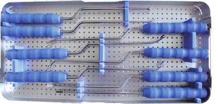
8 13 Instruments pplicator Outer Shaft pplicator Inner Shaft Osteotome, straight Rasp, bayoneted Rasp, angled, bayoneted Ring urette, straight, bayoneted urette, rectangular, bayoneted urette, rectangular, angled, left, bayoneted urette, rectangular, angled, right, bayoneted Impactor, curved, bayoneted pplicator Knob Removal Forceps ancellous one Impactor Packing lock Slide Hammer ombined Hammer 14


9 Rongeur, straight, 4.0 mm Soft Tissue Retractor, width 8mm Soft Tissue Retractor, width 10mm T-Handle With Quick oupling Shaver for Intervertebral Discs, 7mm Shaver for Intervertebral Discs, 9mm Shaver for Intervertebral Discs, 11mm Shaver for Intervertebral Discs, 13mm Shaver for Intervertebral Discs, 15mm Rongeur, curved, 4.0 mm Laminectomy Punch, 4.0 mm Lamina Spreader Soft Tissue Retractor, width 6mm 16


10 Trial Implant, 7mm, Trial Implant, 9mm, Trial Implant, 11mm, Trial Implant, 13mm, Trial Implant, 15mm, TLIF Instrument ase 18
T-PAL. Transforaminal Posterior Atraumatic Lumbar Cage System.
 T-PAL. Transforaminal Posterior Atraumatic Lumbar Cage System. Technique Guide This publication is not intended for distribution in the USA. Instruments and implants approved by the AO Foundation. Image
Interbody fusion cage for the transforaminal approach. Travios. Surgical Technique
 Interbody fusion cage for the transforaminal approach Travios Surgical Technique Image intensifier control This description alone does not provide sufficient background for direct use of DePuy Synthes
SynCage-C short. Surgical Technique. This publication is not intended for distribution in the USA.
 SynCage-C short Surgical Technique This publication is not intended for distribution in the USA. Instruments and implants approved by the AO Foundation. Table of contents Implants 2 Indications/contra-indications
Posterior Lumbar Interbody Fusion System
 Px Posterior Lumbar Interbody Fusion System Px PEEK INTERBODY FUSION SYSTEM INDICATIONS FOR USE The Innovasis Px PEEK IBF System is an intervertebral body fusion device for use in patients with degenerative
Surgical technique. SynCage-C short
 Surgical technique SynCage-C short Table of contents Implants 2 Indications/contra-indications 3 Surgical technique 4 Image intensifier control Warning This description is not sufficient for immediate
Technique Guide. T-PAL. Transforaminal posterior atraumatic lumbar spacer system.
 Technique Guide T-PAL. Transforaminal posterior atraumatic lumbar spacer system. Table of Contents Introduction T-PAL 2 AO Principles 4 Indications and Contraindications 5 Surgical Technique Preparation
SynCage. Surgical Technique. This publication is not intended for distribution in the USA. Instruments and implants approved by the AO Foundation.
 SynCage Surgical Technique This publication is not intended for distribution in the USA. Instruments and implants approved by the AO Foundation. Image intensifier control Warning This description alone
Royal Oak IBFD System Surgical Technique Posterior Lumbar Interbody Fusion (PLIF)
") Royal Oak IBFD System Surgical Technique Posterior Lumbar Interbody Fusion (PLIF) Preoperative Planning Preoperative planning is necessary for the correct selection of lumbar interbody fusion devices.
Royal Oak IBFD System Surgical Technique Posterior Lumbar Interbody Fusion (PLIF) Preoperative Planning Preoperative planning is necessary for the correct selection of lumbar interbody fusion devices.
EIT TLIF Cage. For Natural Bone Ingrowth with EIT Cellular Titanium
 EIT TLIF Cage For Natural Bone Ingrowth with EIT Cellular Titanium EIT TLIF Cage Surgical Technique EIT Cellular Titanium provides active fusion area» ~ 80% porosity» ~ 650 µm diamond pore size» open interconnected
EXACTECH SPINE. Operative Technique. Cervical Spacer System. Surgeon focused. Patient driven. TM
 EXACTECH SPINE Operative Technique Cervical Spacer System Surgeon focused. Patient driven. TM ACAPELLA ONE Acapella One Cervical Spacer System is an anterior cervical discectomy and fusion device with
FACET WEDGE. Facet joint fixation device.
 FACET WEDGE. Facet joint fixation device. Technique Guide Synthes FACET WEDGE Technique Guide /44 Synthes FACET WEDGE Technique Guide /44 Table of Contents Introduction FACET WEDGE 3 AO Principles 4 Indications
nva Anterior Lumbar Interbody Fusion System
 nva Anterior Lumbar Interbody Fusion System 1 IMPORTANT INFORMATION FOR PHYSICIANS, SURGEONS, AND/OR STAFF The nv a, nv p, and nv t are an intervertebral body fusion device used in the lumbar spine following
SYNCAGE EVOLUTION. This publication is not intended for distribution in the USA. SURGICAL TECHNIQUE
 SYNCAGE EVOLUTION This publication is not intended for distribution in the USA. SURGICAL TECHNIQUE Image intensifier control Warning This description alone does not provide sufficient background for direct
nvt Transforaminal Lumbar Interbody Fusion System
 nvt Transforaminal Lumbar Interbody Fusion System 1 IMPORTANT INFORMATION FOR PHYSICIANS, SURGEONS, AND/OR STAFF The nv a, nv p, and nv t are an intervertebral body fusion device used in the lumbar spine
Alamo T Transforaminal Lumbar Interbody System Surgical Technique
 Transforaminal Lumbar Interbody System Surgical Technique Table of Contents Indications and Device Description.............. 1 Alamo T Implant Features and Instruments...........2 Surgical Technique......................
Contact Fusion Cage. Surgical Technique
 Contact Fusion Cage Surgical Technique Image intensifier control This description alone does not provide sufficient background for direct use of DePuy Synthes products. Instruction by a surgeon experienced
Minimally Invasive Posterior Instruments
 A Comprehensive Set Supporting Both Direct and Transforaminal Posterior Approaches to the Lumbar Spine Minimally Invasive Posterior Instruments Support mini-open procedures and ideal for use with Minimally
VTI INTERFUSE T SURGICAL TECHNIQUE FORWARD THINKING FOR THE BACK. 1/20
 VTI INTERFUSE T SURGICAL TECHNIQUE FORWARD THINKING FOR THE BACK. 1/20 CONTENTS InterFuse T Product Description Indications for Use X-Ray Marker Locations Product Specifications Instrument Set 3 4 5 STEP
nvp Posterior Lumbar Interbody Fusion System
 nvp Posterior Lumbar Interbody Fusion System 1 IMPORTANT INFORMATION FOR PHYSICIANS, SURGEONS, AND/OR STAFF The nv a, nv p, and nv t are an intervertebral body fusion device used in the lumbar spine following
Surgical Technique. Apache Posterior Lumbar Interbody Fusion Apache Transforaminal Lumbar Interbody Fusion
 Surgical Technique Apache Posterior Lumbar Interbody Fusion Apache Transforaminal Lumbar Interbody Fusion 2 Table of Contents Page Preoperative Planning 4 Patient Positioning 5 Disc Exposure 5 Disc and
Luminary ALIF. Disc preparation and implant insertion instruments.
 Luminary ALIF. Disc preparation and implant insertion instruments. Technique Guide Instruments and implants approved by the AO Foundation Table of Contents Introduction Luminary ALIF 2 AO Principles 4
SURGICAL TECHNIQUE MANUAL. InterFuse T
 1 CONTENTS InterFuse T Product Description 3 Indications for Use 3 X-Ray Marker Locations 4 Product Specifications 4 Instrument Set 5 Step 1 Preoperative Planning 8 Patient Positioning 8 Step 2 Disc Removal
VTI INTERFUSE S SURGICAL TECHNIQUE FORWARD THINKING FOR THE BACK.
 VTI INTERFUSE S SURGICAL TECHNIQUE FORWARD THINKING FOR THE BACK. CONTENTS InterFuse S Product Description Indications for Use X-Ray Marker Locations and Product Specifications Instrument Set 3 4 5-7 STEP
Cervical Spacer System surgical technique
 Blackhawk TM Cervical Spacer System surgical technique Blackhawk TM The BLACKHAWK Cervical Spacer System is designed to provide biomechanical stabilization as an adjunct to fusion. Spinal fixation should
VECTRA-T SURGICAL TECHNIQUE. The Translational Anterior Cervical Palate System. This publication is not intended for distribution in the USA.
 VECTRA-T The Translational Anterior Cervical Palate System This publication is not intended for distribution in the USA. SURGICAL TECHNIQUE Image intensifier control This description alone does not provide
L-VARLOCK. Posterior Lumbar Cage with adjustable lordosis. S urgical T echnique
 L-VARLOCK Posterior Lumbar Cage with adjustable lordosis S urgical T echnique Introduction Designed and manufactured by KISCO International, L-VARLOCK cages are made of titanium alloy Ti 6AI 4V (standards
Oblique Posterior Atraumatic Lumbar cage system OPAL. Surgical Technique
 Oblique Posterior Atraumatic Lumbar cage system OPAL Surgical Technique Image intensifier control This description alone does not provide sufficient background for direct use of DePuy Synthes products.
PEEK Cage for Posterior Lumbar Interbody Fusion (PLIF) Plivios Revolution. Surgical Technique
 Plivios Revolution. Surgical Technique") PEEK Cage for Posterior Lumbar Interbody Fusion (PLIF) Plivios Revolution Surgical Technique Image intensifier control This description alone does not provide sufficient background for direct use of DePuy
PEEK Cage for Posterior Lumbar Interbody Fusion (PLIF) Plivios Revolution Surgical Technique Image intensifier control This description alone does not provide sufficient background for direct use of DePuy
Surgical Technique Manual
 InterFuse S Interbody Fusion System Surgical Technique Manual VERTEBRAL TECHNOLOGIES MS 4043-02 Rev. O Product Overview Introduction The VTI InterFuse S implant is an interbody fusion device that combines
Imola Lateral IBF System Surgical Technique
 Imola Lateral IBF System Surgical Technique IMOLA CIRCUIT TABLE OF CONTENTS Design Rationale Instructions for Use Surgical Technique 1. Table Mounting 2. Surgical Planning & Targeting 3. Access and Preparation
PILLAR AL. Anterior Lumbar Interbody Fusion (ALIF) and Partial Vertebral Body Replacement (pvbr) PEEK Spacer System OPERATIVE TECHNIQUE
 and Partial Vertebral Body Replacement (pvbr) PEEK Spacer System OPERATIVE TECHNIQUE") PILLAR AL PEEK Spacer System Anterior Lumbar Interbody Fusion (ALIF) and Partial Vertebral Body Replacement (pvbr) OPERATIVE TECHNIQUE Table of Contents 1 INTRODUCTION 2 PRE-OPERATIVE TECHNIQUE 3 OPERATIVE
PILLAR AL PEEK Spacer System Anterior Lumbar Interbody Fusion (ALIF) and Partial Vertebral Body Replacement (pvbr) OPERATIVE TECHNIQUE Table of Contents 1 INTRODUCTION 2 PRE-OPERATIVE TECHNIQUE 3 OPERATIVE
ACIS Anterior Cervical Interbody Spacer
 Implants and Instruments for Interbody Fusion Available in both PEEK and ProTi 360º Titanium Integrated Technology ACIS Anterior Cervical Interbody Spacer Surgical Technique Image intensifier control This
TABLE OF CONTENTS. ShurFit Anterior Cervical Interbody Fusion (ACIF) System Overview 2. Implant Specifications 3. Instrument Features 4
 System Overview 2. Implant Specifications 3. Instrument Features 4") Surgical Technique TABLE OF CONTENTS ShurFit Anterior Cervical Interbody Fusion (ACIF) System Overview 2 Product Highlights 2 Indications 2 Implant Specifications 3 Instrument Features 4 Surgical Technique
Surgical Technique TABLE OF CONTENTS ShurFit Anterior Cervical Interbody Fusion (ACIF) System Overview 2 Product Highlights 2 Indications 2 Implant Specifications 3 Instrument Features 4 Surgical Technique
M.I.S. MAKE IT SMART IN ONE SYSTEM. Surgical Technique. Hip Knee Spine Navigation
 M.I.S. MAKE IT SMART IN ONE SYSTEM Surgical Technique Hip Knee Spine Navigation M.U.S.T. Mini Open Surgical Technique Hip Knee Spine Navigation 2 C O N T E N T S 1 INTRODUCTION 4 2 SURGICAL TECHNIQUE 5
CROSS -FUSE P E E K V B R / I B F SYST E M
 S U R G I C A L T E C H N I Q U E CROSS -FUSE P E E K V B R / I B F SYST E M S U R G I C A L S Y S T E M O V E R V I E W 2 CROSS-FUSE P E E K V B R / I B F S Y S T E M S U R G I C A L T E C H N I Q U E
SURGICAL TECHNIQUE ROI-T TM TLIF INTERSOMATIC IMPLANT TRANS-FORAMINAL APPROACH
 TLIF INTERSOMATIC IMPLANT TRANS-FORAMINAL APPROACH Table of Contents page Step 1 - Articular resection.................................................................................. 3 Step 2 - Pedicle
SynCage Surgical Technique
 SynCage Surgical Technique This publication is not intended for distribution in the USA. Instruments and implants approved by the AO Foundation. Contents Product Overview.........................................
ACIS Anterior Cervical Interbody Spacer
 An enhanced system of implants and instruments for interbody fusion ACIS Anterior Cervical Interbody Spacer Surgical Technique Image intensifier control This description alone does not provide sufficient
Alamo C. Cervical Interbody System Surgical Technique. An Alliance Partners Company
 Cervical Interbody System Surgical Technique Table of Contents Indications for Use................................1 Device Description............................... 1 Alamo C Instruments..............................
XRL A modular expandable radiolucent vertebral body replacement system
 XRL A modular expandable radiolucent vertebral body replacement system This publication is not intended for distribution in the USA. SURGICAL TECHNIQUE Table of Contents Introduction XRL 2 AO Spine Principles
Thoracolumbar Solutions. Zyston Curve. Interbody Spacer System. Surgical Technique Guide
 Thoracolumbar Solutions Zyston Curve Interbody Spacer System Surgical Technique Guide 2 Zyston Curve Interbody Spacer System Surgical Technique Guide The Zyston Curve Interbody System is designed to optimize
SYNEX The vertebral body replacement with ratchet mechanism
 SYNEX The vertebral body replacement with ratchet mechanism Instruments and implants approved by the AO Foundation. This publication is not intended for distribution in the USA. SURGICAL TECHNIQUE Image
Solitaire Anterior Spinal System
 Surgical Technique Solitaire Anterior Spinal System Independent Stabilization for the Anterior Column Available in Titanium and Contents Introduction... Page 1 Design Features... Page 2 Instruments...
Plivios and Plivios chronos. Radiolucent cage system for posterior lumbar interbody fusion.
 Plivios and Plivios chronos. Radiolucent cage system for posterior lumbar interbody fusion. Surgical Technique This publication is not intended for distribution in the USA. Instruments and implants approved
product overview Implant heights range from 8mm-20mm in 2mm increments, with two lordocic angle options of 6 and 12.
 ETHOS A-Spacer PEEK System Surgical Technique Guide Synchronizing Medical Innovation with Global Markets product overview The SyncMedical Ethos PEEK IBF System is an intervertebral body fusion device for
SYNFIX EVOLUTION SECURED SPACER SYSTEM
 SYNFIX EVOLUTION SECURED SPACER SYSTEM Instruments and implants for stand-alone anterior lumbar interbody fusion Instruments and implants approved by the AO Foundation. This publication is not intended
TSLP Thoracolumbar Spine Locking Plate
 Anterior thoracolumbar spine locking plate TSLP Thoracolumbar Spine Locking Plate Surgical Technique Image intensifier control This description alone does not provide sufficient background for direct use
100 Interpace Parkway Parsippany, NJ
 100 Interpace Parkway Parsippany, NJ 07054 www.biometspine.com 800-526-2579 All trademarks are the property of Biomet, Inc. or one of its subsidiaries, unless otherwise indicated. Rx Only. 2009 EBI, LLC.
Apache Cervical Interbody Fusion Device. Surgical Technique. Page of 13. LC-005 Rev F
 LC-005 Rev F Apache Cervical Interbody Fusion Device Page of 13 Surgical Technique INDICATIONS: When used as an intervertebral body fusion device, the Genesys Spine Interbody Fusion System is indicated
LUMBAR POSTERIOR MINIMALLY INVASIVE SYSTEM. Surgical Technique
 LUMBAR POSTERIOR MINIMALLY INVASIVE SYSTEM Surgical Technique Joint Spine Sports Med M.U.S.T. Mini Open Surgical Technique Joint Spine Sports Med CAUTION Federal law (USA) restricts this device to sale
The Implant. (Klappen außen sind nur 192 mm breit!)
") SEMIAL product information The Implant SEMIAL implants are designed to restore interbody vertebral disc height and maintain solid bony fusion when used in conjunction with bone graft material and supportive
SEMIAL product information The Implant SEMIAL implants are designed to restore interbody vertebral disc height and maintain solid bony fusion when used in conjunction with bone graft material and supportive
In-Space. Interspinous distraction through a mini-open, posterior, unilateral approach.
 In-Space. Interspinous distraction through a mini-open, posterior, unilateral approach. Surgical Technique Posterior Approach PRODUCT OBSOLETED 30th September 2017 DSEM/SPN/0915/0348(1) This publication
T.L.I.F. Surgical Technique. Featuring the T.L.I.F. SG Instruments, VG2 PLIF Allograft, and the MONARCH Spine System.
 Surgical Technique T.L.I.F. Transforaminal Lumbar Interbody Fusion Featuring the T.L.I.F. SG Instruments, VG2 PLIF Allograft, and the MONARCH Spine System. CONSULTING SURGEON Todd Albert, M.D. Rothman
Fusion Device. Surgical Technique. Cervical Interbody Fusion with Trabecular Metal Technology
 TM-S Fusion Device Surgical Technique Cervical Interbody Fusion with Trabecular Metal Technology 2 TM-S Fusion Device Surgical Technique Disclaimer This surgical technique is not intended for use in the
C-THRU Anterior Spinal System
 C-THRU Anterior Spinal System Surgical Technique Manufactured From Contents Introduction... Page 1 Design Features... Page 2 Instruments... Page 3 Surgical Technique... Page 4 Product Information... Page
Cervical Solutions. Optio-C Anterior Cervical Plate. with Allograft/Autograft. Surgical Technique Guide
 Cervical Solutions Optio-C Anterior Cervical Plate with Allograft/Autograft Surgical Technique Guide 2 Optio-C Anterior Cervical Plate with Allograft/Autograft Surgical Technique Guide The Optio-C System
Technique Guide. Zero-P VA. Variable angle zero-profile anterior cervical interbody fusion (ACIF) device.
 device.") Technique Guide Zero-P VA. Variable angle zero-profile anterior cervical interbody fusion (ACIF) device. Image intensifier control Warning This description alone does not provide sufficient background
Technique Guide Zero-P VA. Variable angle zero-profile anterior cervical interbody fusion (ACIF) device. Image intensifier control Warning This description alone does not provide sufficient background
Technique Guide. Oracle Spacer System. Instruments and implants for a direct lateral approach to the lumbar spine.
 Technique Guide Oracle Spacer System. Instruments and implants for a direct lateral approach to the lumbar spine. Table of Contents Introduction Oracle Spacer System 2 AO Principles 4 Indications 5 Surgical
INTERVERTEBRAL BODY FUSION DEVICE. Surgical Technique
 INTERVERTEBRAL BODY FUSION DEVICE Surgical Technique Joint Spine Sports Med MectaLIF Oblique & Posterior Surgical Technique 2 INDEX 1. INTRODUCTION 4 1.1 Materials & Markers 5 2. INDICATIONS 6 3. CONTRAINDICATIONS
Commander Cervical Cage - SURGICAL TECHNIQUE
 Commander Cervical Cage - SURGICAL TECHNIQUE D e s i g n e d to c l o s e l y f i t yo u! Commander Cervical Cage - SURGICAL TECHNIQUE Indications Commander cervical cages are designed primarly for restoring
InFix. Anterior Lumbar Device. Surgical Technique Guide
 InFix Anterior Lumbar Device Surgical Technique Guide 2 InFix Anterior Lumbar Device Surgical Technique Guide InFix Anterior Lumbar System s modular design is intended to restore lordosis, disc height
Surgical Technique. Apache Anterior Lumbar Interbody Fusion
 Surgical Technique Apache Anterior Lumbar Interbody Fusion 2 Table of Contents Page Preoperative Planning 4 Patient Positioning 4 Disc and Endplate Preparation 4 Distraction/Size Selection 5 Implantation
Advantage ALIF. Keith Shevlin Managing Director
 Advantage ALIF Unit 10, 9-11 Myrtle Street, Crows Nest NSW 2065 Keith Shevlin Managing Director keithshevlin@precisionsurgical.com.au Advantage ALIF Introduction & Indications for Use 1 Surgical Technique
Synex System TECHNIQUE GUIDE. An expandable vertebral body replacement device
 Synex System TECHNIQUE GUIDE An expandable vertebral body replacement device Original Instruments and Implants of the Association for the Study of Internal Fixation AO ASIF Synex System Overview The Synex
OPAL SURGICAL TECHNIQUE. Oblique Posterior Atraumatic Lumbar cage system
 OPAL Oblique Posterior Atraumatic Lumbar cage system Instruments and implants approved by the AO Foundation. This publication is not intended for distribution in the USA. SURGICAL TECHNIQUE Image intensifier
Ardis. Surgical Technique. Interbody System. Solutions by the people of Zimmer Spine. zimmerspine.com
 Ardis Interbody System Surgical Technique Solutions by the people of Zimmer Spine. zimmerspine.com A more advanced interbody solution. From the people of Zimmer Spine. The easily inserted Ardis Interbody
The vertebral body replacement with ratchet mechanism. Synex. Surgical Technique
 The vertebral body replacement with ratchet mechanism Synex Surgical Technique Image intensifier control This description alone does not provide sufficient background for direct use of DePuy Synthes products.
Surgical Technique INTERSOMATIC CERVICAL CAGE
 R INTERSOMATIC CERVICAL CAGE NEOCIF IMPLANTS NEOCIF is an implant designed to make anterior cervical interbody fusion (ACIF) easier and to remove the need for structural autologous graft. The cage is made
Patient Information MIS LLIF. Lateral Lumbar Interbody Fusion Using Minimally Invasive Surgical Techniques
 Patient Information MIS LLIF Lateral Lumbar Interbody Fusion Using Minimally Invasive Surgical Techniques Table of Contents Anatomy of Spine....2 General Conditions of the Spine....4 What is Spondylolisthesis....5
T.L.I.F. Transforaminal Lumbar Interbody Fusion
 T.L.I.F. Transforaminal Lumbar Interbody Fusion Cover Surgical Header Technique Sub Guide header Introduction (T.L.I.F. ) technique has gained wide acceptance Additionally, the T.L.I.F. procedure avoids
Module: #15 Lumbar Spine Fusion. Author(s): Jenni Buckley, PhD. Date Created: March 27 th, Last Updated:
: Jenni Buckley, PhD. Date Created: March 27 th, Last Updated:") Module: #15 Lumbar Spine Fusion Author(s): Jenni Buckley, PhD Date Created: March 27 th, 2011 Last Updated: Summary: Students will perform a single level lumbar spine fusion to treat lumbar spinal stenosis.
Module: #15 Lumbar Spine Fusion Author(s): Jenni Buckley, PhD Date Created: March 27 th, 2011 Last Updated: Summary: Students will perform a single level lumbar spine fusion to treat lumbar spinal stenosis.
POSTERIOR SPINE TRUSS SYSTEM
 POSTERIOR SPINE TRUSS SYSTEM ORDERING & SHIPPING ALL FIELDS ARE REQUIRED ORDER FORM PLEASE PRINT LEGIBLY RECEIVING YOUR PSTS TRAYS & IMPLANTS All implant bins and trays have a warehouse number on them
TECHNICAL BROCHURE. Capture Facet Fixation System
 TECHNICAL BROCHURE Capture Facet Fixation System Table of Contents Product Overview...2 Instruments...4 Capture Facet Screw Surgical Technique Patient Preparation and Positioning...6 Guide Pin Placement...7
UniWallis TM Posterior Dynamic Stabilization System
 UniWallis TM Posterior Dynamic Stabilization System Surgical Technique Solutions by the people of Zimmer Spine. zimmerspine.eu Table of Contents Indications/Contraindications 2 UniWallis Instruments 3
ECD EXPANDABLE CORPECTOMY DEVICE Continuously Expandable Vertebral Body Replacement for Tumour Cases
 ECD EXPANDABLE CORPECTOMY DEVICE Continuously Expandable Vertebral Body Replacement for Tumour Cases Instruments and implants approved by the AO Foundation. This publication is not intended for distribution
BAK/C Cervical Anterior Interbody Fusion System
 Surgical Technique BAK/C Cervical Anterior Interbody Fusion System The Comfortable Choice for Cervical Fusion BAK/C Cervical Surgical Technique 1 The BAK/C Cervical Fusion System is an alternative to conventional
CSLP-Cervical Spine Locking Plate
 For anterior, cervical fixation CSLP-Cervical Spine Locking Plate Surgical Technique Image intensifier control This description alone does not provide sufficient background for direct use of DePuy Synthes
Thoracolumbar Spine Locking Plate (TSLP) System. A low-profile plating system for anterior stabilization of the thoracic and lumbar spine.
 System. A low-profile plating system for anterior stabilization of the thoracic and lumbar spine.") Thoracolumbar Spine Locking Plate (TSLP) System. A low-profile plating system for anterior stabilization of the thoracic and lumbar spine. Technique Guide Instruments and implants approved by the AO Foundation
Thoracolumbar Spine Locking Plate (TSLP) System. A low-profile plating system for anterior stabilization of the thoracic and lumbar spine. Technique Guide Instruments and implants approved by the AO Foundation
Aesculap Spine T-Space PEEK. Transforaminal Lumbar Interbody Fusion System
 Aesculap Spine T-Space PEEK Transforaminal Lumbar Interbody Fusion System Forword Growing socio-economic pressure in conjunction with the high incidence of spinal disorders and consequent conditions calls
EFSPINE CERVICAL COMBINED SET DISC PROTHESIS ORGANIZER BOX
 EFSPINE CERVICAL COMBINED SET INSTRUMENTS CERVICAL CAGE & DISC PROTHESIS ORGANIZER BOX Cervical Thoracic Thoraco - Lumbar Sacral EFSPINE CERVICAL COMBINED SET CERVICAL IMPLANTS INTRODUCTION Cervical Disc
In-Space. Percutaneous interspinous distraction.
 In-Space. Percutaneous interspinous distraction. Surgical Technique PRODUCT OBSOLETED 30th September 207 DSEM/SPN/095/0344() This publication is not intended for distribution in the USA. Instruments and
Technique Guide. StenoFix. Interspinous distraction after surgical decompression.
 Technique Guide StenoFix. Interspinous distraction after surgical decompression. Table of Contents Introduction StenoFix 2 Indications and Contraindications 4 Surgical Technique Preoperative Planning
Thoracolumbar Solutions. TM Ardis. Interbody System. Surgical Technique Guide
 Thoracolumbar Solutions TM Ardis Interbody System Surgical Technique Guide 2 TM Ardis Interbody System Surgical Technique Guide Trabecular Metal Technology TM Ardis Interbody System Surgical Technique
Patient Information MIS LLIF. Lateral Lumbar Interbody Fusion Using Minimally Invasive Surgical Techniques
 Patient Information MIS LLIF Lateral Lumbar Interbody Fusion Using Minimally Invasive Surgical Techniques Table of Contents Anatomy of Spine...2 General Conditions of the Spine....4 What is Spondylolisthesis....5
Surgical Technique. TraXis. Precision. Transforaminal Lumbar Interbody Fusion Spacer. The Art & Science of Spine Surgery
 Surgical Technique Precision TraXis Transforaminal Lumbar Interbody Fusion Spacer The Art & Science of Spine Surgery Table of Contents Introduction 3 Indications 4 Key Instruments 5 Surgical Technique
Replacement Device A modular expandable radiolucent vertebral body replacement system
 XRL Vertebral Body Replacement Device A modular expandable radiolucent vertebral body replacement system SURGICAL TECHNIQUE TABLE OF CONTENTS Introduction XRL System 2 AO Principles 5 Indications and Contraindications
Surgical technique. synex. The vertebral body replacement with ratchet mechanism.
 Surgical technique synex. The vertebral body replacement with ratchet mechanism. Table of contents Indications and contraindications 2 Implants 3 Surgical technique 4 Cleaning of instruments 10 Optional
SYNFIX. LR Stand Alone Spacer. Instruments and implants for stand alone anterior lumbar interbody fusion (ALIF). Technique Guide
. Technique Guide") SYNFIX LR Stand Alone Spacer. Instruments and implants for stand alone anterior lumbar interbody fusion (ALIF). Technique Guide Table of Contents Introduction SYNFIX LR Stand Alone Spacer 2 AO Principles
SYNFIX LR Stand Alone Spacer. Instruments and implants for stand alone anterior lumbar interbody fusion (ALIF). Technique Guide Table of Contents Introduction SYNFIX LR Stand Alone Spacer 2 AO Principles
SURGICAL TECHNIQUE GUIDE TRESTLE. Anterior Cervical Plating System
 SURGICAL TECHNIQUE GUIDE TRESTLE Anterior Cervical Plating System 2 SURGICAL TECHNIQUE GUIDE SURGICAL TECHNIQUE GUIDE System Features Large window enables visualization of graft site and end plates Screw
Technique Guide. ECD Expandable Corpectomy Device. Continuously Expandable Vertebral Body Replacement for Tumour Cases.
 Technique Guide ECD Expandable Corpectomy Device. Continuously Expandable Vertebral Body Replacement for Tumour Cases. Table of Contents Introduction Overview 2 AO ASIF Principles 4 Indications and Contraindications
Silverstone Interbody System Surgical Technique
 Silverstone Interbody System Surgical Technique TABLE OF CONTENTS Design Rationale Instructions for Use Surgical Technique 1. Disc Space Preparation 2. Distraction 3. Implant Selection 4. Implant Placement
Apache Interbody Surgical Technique. LC004 Rev F
 LC004 Rev F Apache Interbody Surgical Technique Apache Anterior Lumbar Interbody Fusion Surgical Technique INDICATIONS: When used as an intervertebral body fusion device, the Genesys Spine Interbody Fusion
Technique Guide. Insight Retractor. Minimal invasive access system to the posterior thoracolumbar spine.
 Technique Guide Insight Retractor. Minimal invasive access system to the posterior thoracolumbar spine. Table of Contents Introduction Insight Retractor 2 AO Principles 4 Indications and Contraindications
Valencia Pedicle Screw Surgical Technique
 Valencia Pedicle Screw Surgical Technique VALENCIA CIRCUIT TABLE OF CONTENTS Design Rationale Indications for Use Surgical Technique 1. Pedicle Preparation 2. Screw Insertion 3. Rod Placement 4. Locking
T-PAL Spacer System. Transforaminal posterior atraumatic lumbar spacer system.
 T-PAL Spacer System. Transforaminal posterior atraumatic lumbar spacer system. One instrument, one technique Accommodates both open and MIS approaches A PEEK implant that works with patient anatomy Streamlined
Surgical Technique Guide
 Sacroiliac Joint Fusion System Surgical Technique Guide Moving Life Forward Table of Contents SiCure Implant Overview...2 SiCure System Information...3 X-ray Basics...4 Patient Positioning....5 Surgical
Spinal Correction FRA Spacer System. For use with the Small Stature FRA Spacer and the FRA Spacer.
 Spinal Correction FRA Spacer System. For use with the Small Stature FRA Spacer and the FRA Spacer. Technique Guide Instruments and implants approved by the AO Foundation Table of Contents Introduction