Cervical Solutions. Optio-C Anterior Cervical Plate. with Allograft/Autograft. Surgical Technique Guide
|
|
|
- Duane Benson
- 5 years ago
- Views:
Transcription


1 Cervical Solutions Optio-C Anterior Cervical Plate with Allograft/Autograft Surgical Technique Guide


2 2 Optio-C Anterior Cervical Plate with Allograft/Autograft Surgical Technique Guide The Optio-C System provides a zero-profile cervical fusion option with a variety of materials, footprints and geometries.
3 Optio-C Anterior Cervical Plate with Allograft/Autograft Surgical Technique Guide 3 Optio-C Anterior Cervical Plate with Allograft/Autograft Surgical Technique Optio-C System Overview... 4 Surgical Technique Option 1: Optio-C Structural Allograft... 6 Inserter Guide... 6 ATO Inserter Guide (Optional) Freehand Screw Insertion Surgical Technique Option 2: Structural Allograft/Autograft of the Same Height as the Optio-C Plate Inserter Guide ATO Inserter Guide (Optional) Freehand Screw Insertion Removal/Revision Surgical Technique Tray Layouts Visual Instrument Guide Important Information on the Optio-C Anterior Cervical Plate with Allograft/Autograft Global Availability Some instruments and/or implants may not be available in some geographic regions. Check with local representation for product availability.
 one Optio-C structural allograft or (2) one structural allograft/autograft of the same height as the Optio-C Plate.")
4 4 Optio-C Anterior Cervical Plate with Allograft/Autograft Surgical Technique Guide Optio-C System Overview The Optio-C System is composed of one Optio-C Anterior Cervical Plate and three Optio-C bone screws, and is designed for use with one of the following: (1) one Optio-C structural allograft or (2) one structural allograft/autograft of the same height as the Optio-C Plate. The Optio-C Plate and Allograft are used to provide structural stability in skeletally mature individuals following discectomy and are offered in multiple contours, lordotic angles, footprints and heights to accommodate variations in cervical anatomy. Optio-C Plates The Optio-C Plate is a component of the Optio-C Anterior Cervical System and is intended to be used only in anterior surgical procedures. The Optio-C Plate must be used with three Optio-C bone screws and is designed to be used with either one of the following: One Optio-C structural allograft or One structural allograft/autograft of the same height as the plate The Optio-C Plate and structural allograft are supplied sterile to the end user. The bone screws and instrumentation are supplied non sterile and are intended to be sterilized by the end user. Optio-C Plate (6 12 mm, 1 mm increments) The Optio-C Plate is offered in a one-level configuration, with a standard width and multiple heights, and is designed to facilitate fusion. The plate with a structural allograft/autograft is placed in the cervical disc space, flush with the adjacent vertebral bodies. Bone screws pass through the screw holes of the plate and affix to bone to help prevent implant migration. The implant construct can be implanted in two orientations: standard orientation, two screws cephalad and one screw caudal, or inverted orientation, one screw cephalad and two screws caudal. Optio-C Plates are available in heights of 6 mm to 12 mm. All plates are 16 mm wide. The Optio-C Plate features a one-step, screw-locking mechanism to prevent screw migration. The plate midline is indicated by a black stripe on the anterior face of the plate. Optio-C Allograft The Optio-C Plate and Allograft must be assembled before use as described in this document. The implants are provided in three footprints to meet varying patient anatomy: mm, mm, and mm (depth width) including plate depth connected to the Optio-C Allograft. Optio-C Allograft is provided sterile. Optio-C Allograft is available in heights from 6 mm to 12 mm, in Lordotic (6 ) and Parallel (0 ). Lordotic Description (L W H, Degrees) Item# mm, mm, mm, Parallel Description (L W H, Degrees) Item# mm, mm, mm, Lordotic Parallel
.")


5 Optio-C Anterior Cervical Plate with Allograft/Autograft Surgical Technique Guide 5 All Optio-C Allografts have two notches and a groove to accommodate Optio-C System bone screws. Notches For the lordotic allograft, the anterior height is equal to the size specified, and the posterior height is approximately 1 mm smaller (e.g., for a 7 mm Optio-C lordotic allograft, the posterior height is 6 mm). Optio-C Screws All Optio-C System bone screws are 3.3 mm diameter, variable angle. Both self-drilling DiamondTip and self-tapping screw configurations are available in 12, 14, and 16 mm lengths. Screws feature dual-single lead, cortico-cancellous thread form, and they are color coded by length. Optio-C screws provide a lag effect to ensure the interbody device fits snugly to the anatomy. Self-drilling screws may reduce the surgical steps required to penetrate the cortex of the vertebral body and are distinguished by black stripes on the top of the screw head. Optio-C Plate/Screw Angulation Optio-C System Plates and Screws allow for variable angle placement as follows: The appropriate angle ranges for the lateral screws are 35 to 45 cephalad/caudal and -5 to 5 medial/lateral. The appropriate angle ranges for the midline screw are 35 to 45 cephalad/caudal and 0 to 10 medial/lateral. The midline screw is offset by 1 mm from the plate midline, and it angles 5 medial toward midline. The Optio-C Plate and Allograft can be implanted in two orientations: Standard orientation, two screws cephalad and one screw caudal Inverted orientation, one screw cephalad and two screws caudal Ø3.3 mm Self-Drilling Variable Angle Screws Groove Ø3.3 mm Self-Tapping Variable Angle Screws Optio-C Screw Length Optio-C System screw lengths will terminate at the approximate anterior-posterior distances shown when inserted at nominal trajectory. Standard Inverted Optio-C Allograft Footprint mm mm mm Screw Length 12 mm 14 mm 16 mm
6 6 Optio-C Anterior Cervical Plate with Allograft/Autograft Surgical Technique Guide: Option 1 Surgical Technique Pre-operative Planning and Patient Positioning Exposure, Location and Site Preparation Option 1: Optio-C Structural Allograft Inserter Guide Fig. 1 Step 1 Pre-operatively, the surgeon must identify the proper intervertebral level to fuse using diagnostic techniques such as radiographs, MRI, myelography, discography, patient history and physical examination. Place the patient in supine position. Support the posterior cervical spine to maintain normal lordosis and choose a right- or left-sided approach. Identify the symptomatic level, and make a skin incision to the corresponding pathology. (Fig. 1) Fig. 2 Step 2 The anterior cervical anatomy is exposed in the standard fashion by identifying a dissection plane between the trachea and esophagus. Exposure is then held in place with self-retaining retractors. (Fig. 2)

7 Optio-C Anterior Cervical Plate with Allograft/Autograft Surgical Technique Guide: Option 1 7 Implant Sizing Fig. 3 Fig. 4 Fig. 5 Step 3 For placement adjacent to existing plate hardware, the Optio-C Distraction Pin may be used with a Caspar Distractor over the existing plate hardware in lieu of a Caspar Pin in that vertebral segment. (Fig. 3) NOTE: Ensure that contacting surfaces between the Distraction Pin and existing hardware are clear of bone or soft tissue. NOTE: Optio-C Distraction Pins are intended for single use only and should be disposed of after one use. WARNING: If existing hardware is present, compatibility between the Distraction Pin and the existing hardware should be verified before use. When the Distraction Pin is used with existing hardware, extreme care should be taken to prevent damage to existing hardware. Step 4 Prepare the anatomy to accommodate placement of the Optio-C Plate. It is recommended to insert the Optio-C Plate under distraction. (Fig. 4) WARNING: When preparing the disc space, care should be taken to ensure that an appropriate amount of bone is removed; excessive removal of bone has the potential to cause subsidence, while failing to remove enough bone has the potential to cause poor fusion. Step 5 Choose a parallel or lordotic Trial to match the height and contour of the intervertebral space. Select the appropriate Trial to assess the height of the disc space. Connect the Modular Impaction Cap Handle to the Trial. Ensure that the Trial fits snugly in the disc space when distraction is released. Once the height is determined, select the appropriate plate footprint by using the Trials and Rasps (12 14, 14 16, or 15 18). These instruments equal the shape of the assembled implant (plate + Optio-C Allograft). (Fig. 5) NOTE: Intra-operative imaging can be used to confirm implant sizing. Optio-C System Trials and Rasps are designed to be line-to-line with the implant. Trial and Rasp Color Code Size and Configuration Color 12 mm 14 mm 0 Black 12 mm 14 mm 6 Blue 14 mm 16 mm 0 Green 14 mm 16 mm 6 Yellow 15 mm 18 mm 0 Tan 15 mm 18 mm 6 Orange Distraction Pins Single Prong Double Prong Modular Handle Impaction Cap Implant Trials Parallel and Lordotic ,.026, Implant Rasps Parallel and Lordotic ,.026,
 Confirm the chosen implant sizes and then remove the Optio-C Plate and Optio-C Allograft from their sterile packaging.")


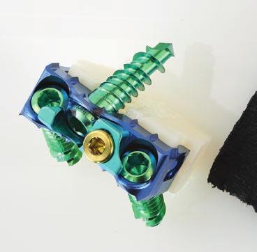
8 8 Optio-C Anterior Cervical Plate with Allograft/Autograft Surgical Technique Guide: Option 1 Implant Assembly Fig. 6 Step 6 The Optio-C implant must be assembled before use. (Fig. 6) Confirm the chosen implant sizes and then remove the Optio-C Plate and Optio-C Allograft from their sterile packaging. Place the Optio-C Allograft into a sterile container and rehydrate with sterile water, sterile saline or the patient s blood. Rehydrate for at least 30 seconds before assembly with the plate. NOTE: Optio-C Plate height and Optio-C Allograft height must match. For example, if the 7 mm Trial fits appropriately, then a 7 mm plate and 7 mm allograft are used. NOTE: The sizing scale on the Implant Assembly Fixture can be used to confirm implant sizes before assembly. Fig. 7 Step 7 Select the Implant Assembly Block station to match the chosen implant footprint. Slide the plate over the short, angled pin. Guide the pin into the plate midline hole until the plate sits flat in the appropriate footprint station. (Fig. 7) NOTE: The gold locking cap needs to be located on the left side of the angled pin. Fig. 8 Step 8 Before connecting the rehydrated allograft to the plate, ensure that the notches for the lateral screws are facing upward. Place the allograft into the Implant Assembly Block behind the plate between the four alignment pins. (Fig. 8) Implant Assembly Block
 Fig.")


9 Optio-C Anterior Cervical Plate with Allograft/Autograft Surgical Technique Guide: Option 1 9 Attaching Implant Fig. 9 Step 9 Use the Implant Assembly Tamp to connect the allograft to the plate until an audible click is heard. (Fig. 9) Fig. 10 Step 10 Confirm visually that the implant is assembled appropriately. Ensure that the plate and allograft sizes match and that the plate screw holes and allograft notches are aligned. (Fig. 10) NOTE: The Optio-C Implant can be loaded onto either Optio-C Inserter Guide directly from the Implant Assembly Block. Fig. 11 Step 11 Assemble the Inserter Guide to the Modular Impaction Cap Handle. Ensure that the Inserter sleeve is in the unlocked position by pulling it toward the Modular Handle and rotating the sleeve counter-clockwise to engage the threads. With the gold locking screw oriented on the left and guide circular markings facing upward, insert the Inserter Guide tubes into the plate screw holes until the positive stops are in contact with the plate. (Fig. 11) NOTE: The circular markings on the Inserter Guide should face upward when assembling the plate to the Inserter. These markings are for orientation only, indicating the direction of the two lateral screws (two dots cephalad, two screws point cephalad). Implant Assembly Block Modular Handle Impaction Cap Implant Assembly Tamp Inserter Guide

10 10 Optio-C Anterior Cervical Plate with Allograft/Autograft Surgical Technique Guide: Option 1 Implant Placement Fig. 12 Fig. 13 Fig. 14 Step 12 Ensure that the inserter is fully seated in the plate holes and that the Inserter Guide positive stop is in contact with the plate. Verify the guide holes and lateral plate holes are aligned and that the inserter axis is perpendicular to the anterior face of the plate. (Fig. 12) Step 13 Secure the implant by rotating the sleeve clockwise and sliding the Inserter Guide sleeve toward the plate until it bottoms out on the distal threads. Rotate the sleeve clockwise, engaging the threads until secure. (Fig. 13) Step 14 Once the implant is securely attached to the inserter, insert the implant into the distracted segment. If necessary, use light impaction to advance the plate into the disc space. (Fig. 14) NOTE: Positive stops position the implant flush with the anterior aspect of the vertebral bodies. WARNING: When inserting the implant, ensure a tight fit between the inserter and implant. Release distraction before drilling to prevent shifting. WARNING: When inserting the implant, care should be taken to avoid using excessive force, which has the potential to cause damage to the implant or surrounding tissue. Inserter Guide Modular Handle Impaction Cap
11 Optio-C Anterior Cervical Plate with Allograft/Autograft Surgical Technique Guide: Option 1 11 Lateral Screw Hole Preparation / Screw Placement Fig. 15 Step 15 Ensure that the implant fits snugly between the adjacent vertebrae, and then release distraction while leaving the Inserter Guide attached to the plate. The Modular Handle can be temporarily removed from the inserter to increase visibility for screw preparation and delivery. (Fig. 15) NOTE: If using the Distraction Pin, remove the Distraction Pin with the Caspar Distractor. Fig. 16 Step 16 Assemble the Awl/Drill to the Modular Spin Cap Handle. Create a pilot hole for the first lateral screw hole by placing the Awl/Drill through the guide hole of the Inserter Guide until the positive stop on the Awl/Drill contacts the guide. The Awl/Drill will create a pilot hole 6 mm deep on the screw hole axis (40 ). The Inserter Guide allows the Awl/Drill (Straight, Flexible or U-Joint options) to pass through the guide holes to prepare the two lateral screw holes while the Inserter Guide is secured to the Implant. Intra-operative imaging should be used to verify Awl/Drill position and to determine the appropriate length screw. Remove the Awl/Drill. Repeat the same steps on the contralateral side. Remove the Inserter Guide by rotating the sleeve counter-clockwise and then pulling the inserter sleeve toward the Modular Impaction Cap Handle and pulling the inserter away from the implant. (Fig. 16) NOTE: Lateral screw preparation and placement should precede midline screw preparation and placement. NOTE: An optional Tissue Sleeve assembly can be used over the U-Joint instrumentation if desired. The Tissue Sleeve assembly helps shield the U-Joint from tissue and fixes the instrument tip at a 40 angle. Prior to attaching the Modular Spin Cap Handle to the U-Joint instrument, the U-Joint Sleeve Tip is threaded clockwise onto the U-Joint Sleeve Tube to encase the universal joint. Modular Handle Spin Cap Awls Straight Flexible U-Joint Drills Straight Flexible U-Joint Modular Handle Impaction Cap U-Joint Sleeve U-Joint Sleeve Tube U-Joint Sleeve Tip
12 12 Optio-C Anterior Cervical Plate with Allograft/Autograft Surgical Technique Guide: Option 1 Midline Screw Hole Preparation/ Screw Placement Fig. 17 Fig. 18 Fig. 19 Step 17 Assemble the 2.0 mm Hex Driver and Modular Spin Cap Handle. Load the desired screw onto the Driver and insert the screw through the first lateral screw hole, advancing the screw until the screw head contacts the plate to stabilize the implant provisionally. Ensure the Driver is on axis to the prepared screw trajectory during screw insertion. Repeat on the contralateral side. (Fig. 17) WARNING: During screw insertion, care should be taken to avoid bone screw stripping, which has the potential to cause an unstable screw construct. Step 18 Prepare the midline screw hole using the Fixed Angle Guide or Variable Angle Guide. The appropriate angle ranges for the midline screw are 35 to 45 cephalad/caudal and 0 to 10 medial/lateral. NOTE: The Variable Angle Guide allows for screw trajectories within the acceptable limits. The Fixed Angle Guide is designed for repeatable nominal angle placement. The Fixed Angle Guide or Variable Angle Guide allows the Awl/Drill (Straight, Flexible, or U-Joint options) to prepare for the midline screw hole. Seat the guide tip into the medial screw hole. Place the Awl/Drill through the selected Drill Guide until the positive stop contacts the guide. The Awl/Drill will create a pilot hole 6 mm deep. Intra-operative imaging should be used to verify Awl/Drill position and determine the appropriate length screw. (Fig. 18) Step 19 Remove the Awl/Drill and Guide. Load the desired screw onto the 2.0 mm Hex Driver. Insert the screw through the midline screw hole, advancing the screw until the screw head contacts the plate to stabilize the implant provisionally. Ensure that the Driver is on axis to the prepared screw trajectory during screw insertion and final tightening. (Fig. 19) Modular Handle Spin Cap mm Hex Drivers Straight Flexible U-Joint Guides Fixed Angle (gold end) Variable Angle (silver end) Awls Straight Flexible U-Joint Drills Straight Flexible U-Joint U-Joint Sleeve U-Joint Sleeve Tube U-Joint Sleeve Tip
13 Optio-C Anterior Cervical Plate with Allograft/Autograft Surgical Technique Guide: Option 1 13 Final Tightening of Bone Screws Securing the Locking Cap Fig. 20 Fig. 21 Fig. 22 Step 20 Completely engage the 2.0 mm Hex Driver in each screw head and fully seat all bone screws. (Fig. 20) NOTE: Failure to fully seat the screws could interfere with the final tightening of the locking mechanism. NOTE: The locking mechanism comes in the unlocked position. Do not turn the gold locking screw counterclockwise for any reason other than revision surgery. NOTE: Confirm that the screws are fully seated before securing the gold locking screw. If the teal locking cap does not move freely over the screw heads, re-check whether the bone screws are fully seated. Step 21 Once all screws are fully seated within the plate, assemble the gold Locking Cap Driver and Torque Limiting Handle. Insert the Locking Cap Driver into the gold locking screw. Ensure that the tip of the Driver is fully seated in the screw pocket and that the Driver is on axis to the locking screw. (Fig. 21) Step 22 Turn the Driver clockwise. As the screw tightens, the teal locking cap will slide over the screw heads. Turn the Torque Limiting Handle until an audible click is heard when the Locking Mechanism is tightened to 4 in-lb. The Locking Mechanism and Torque Limiting Handle will provide visual, audible and tactile confirmation that the locking mechanism is fully secured and the screw heads are partially covered. (Fig. 22) Torque Limiting Handle Locking Cap Driver
 Fig.")

14 14 Optio-C Anterior Cervical Plate with Allograft/Autograft Surgical Technique Guide: Option 1 Surgical Technique Option 1: Optio-C Structural Allograft ATO Inserter Guide (Optional) Planning, Positioning and Exposure Attaching the Implant to the ATO Inserter Guide Fig. 23 Step 1 Repeat step 1, Pre-Operative Planning, through step 10, Implant Assembly, on pages 6 9. (Fig. 23) Fig. 24 Step 2 Assemble the ATO Inserter Guide to the Modular Impaction Cap Handle. The ATO Inserter Guide grasps the outside of the plate by engaging the plate pockets. With the gold locking screw oriented on the left and guide circular markings facing upward, attach the ATO Inserter Guide around the outside of the plate. The ATO Inserter Guide snaps into place when the tabs are fully seated in the plate pockets. (Fig. 24, top) NOTE: The circular markings on the ATO Inserter Guide should face upward when assembling the plate to the inserter. These markings are for orientation only, indicating the direction the two lateral screws will point in situ. (Fig. 24, bottom) Modular Handle Impaction Cap ATO Inserter Guide Optional instrument. Available upon request.
15 Optio-C Anterior Cervical Plate with Allograft/Autograft Surgical Technique Guide: Option 1 15 Implant Placement Fig. 25 Fig. 26 Fig. 27 Step 3 Ensure that the inserter is fully seated on the implant by verifying that the ATO Inserter Guide positive stops are in contact with the plate. Verify that the guide holes and lateral plate holes are aligned, and that the inserter axis is perpendicular to the anterior face of the plate. (Fig. 25) Secure the implant by sliding the ATO Inserter Guide sleeve toward the implant until it bottoms out on the distal end of the ATO Inserter Guide. (Fig. 25, inset) NOTE: When using the ATO Inserter Guide, care should be taken to insert the implant in line to the disc space. Avoid off-axis loading or torsion of the ATO Inserter Guide during insertion of the implant to reduce risk of separating the plate from the allograft. Step 4 Insert the implant into the distracted segment. If necessary, use light impaction to advance the implant into the disc space. (Fig. 26) Step 5 Ensure that the implant fits snugly between the adjacent vertebrae, and then release distraction while leaving the ATO Inserter Guide attached to the implant construct. The Modular Handle can be temporarily removed from the inserter to increase visibility for screw preparation and delivery. (Fig. 27) Modular Handle Impaction Cap ATO Inserter Guide Optional instrument. Available upon request.

16 16 Optio-C Anterior Cervical Plate with Allograft/Autograft Surgical Technique Guide: Option 1 Lateral Screw Hole Preparation/ Screw Placement Fig. 28 Fig. 29 Fig. 30 Step 6 The ATO Inserter Guide allows the Awl, Drill and 2.0 mm Hex Driver (Straight and Flexible options only) to pass through the guide holes for the two lateral screw holes while the ATO Inserter Guide is secured to the implant. The U-Joint instruments are not compatible with the ATO Inserter Guide. Assemble the Awl/Drill to the Modular Spin Cap Handle. Create a pilot hole for the first lateral screw hole by placing the Awl/Drill through the guide hole of the ATO Inserter Guide until the positive stop contacts the ATO Inserter Guide. The Awl/Drill will create a pilot hole 6 mm deep on the screw hole axis (40 ). Intra-operative imaging should be used to verify Awl/Drill position and to determine the appropriate length screw. Remove the Awl/Drill. Repeat the same steps on the contralateral side. (Fig. 28) Step 7 Assemble the 2.0 mm Hex Driver and Modular Spin Cap Handle. Load the desired screw onto the Driver and insert the screw through the first lateral screw hole until the screw head contacts the plate to stabilize the implant provisionally. Ensure that the Driver is on axis to the prepared screw trajectory during screw insertion and final tightening. (Fig. 29) The Driver laser marking approaches the edge of the guide tube to indicate the screw is nearly seated. (Fig. 29, inset) Step 8 Repeat step 7 on the contralateral side. When both lateral screws have been placed, remove the ATO Inserter Guide by sliding the inserter sleeve toward the Modular Impaction Cap Handle and pulling the inserter away from the implant using a gentle, side-to-side motion. (Fig. 30) NOTE: If self-drilling screws are used, the awl/drill steps can be omitted at the discretion of the surgeon. WARNING: During screw insertion, care should be taken to avoid bone screw stripping, which has the potential to cause an unstable screw construct. Modular Handle Spin Cap Awls Straight Flexible Drills Straight Flexible 2.0mm Hex Drivers Straight Flexible
17 Optio-C Anterior Cervical Plate with Allograft/Autograft Surgical Technique Guide: Option 1 17 Midline Screw Hole Preparation/ Screw Placement Fig. 31 Step 9 Prepare the midline screw hole using the Fixed or Variable Drill Guide. The appropriate angle ranges for the midline screws are 35 to 45 cephalad/caudal and 0 to 10 medial/lateral. (Fig. 31) NOTE: The Variable Angle Guide allows for screw trajectories within the acceptable limits. The Fixed Angle Guide is designed for repeatable nominal angle placement. Fig. 32 The Fixed or Variable Drill allows the Awl/Drill (Straight, Flexible, or U-Joint options) to prepare for the midline screw hole. Seat the guide tip into the medial screw hole. Place the Awl/Drill through the selected Drill Guide until the positive stop contacts the guide. The Awl/Drill will create a pilot hole 6 mm deep. Intra-operative imaging should be used to verify Awl or Drill position and determine the appropriate length screw. (Fig. 32) NOTE: An optional Tissue Sleeve assembly may be used over the U-Joint instrumentation if desired. The Tissue Sleeve assembly helps shield the U-Joint from tissue and fixes the instrument tip at a 40 angle. Prior to attaching the Modular Spin Cap Handle to the U-Joint instrument, the U-Joint Sleeve Tip is threaded clockwise onto the U-Joint Sleeve Tube to encase the universal joint. Fig. 33 Step 10 Remove the Awl/Drill and Guide. Load the desired screw onto the 2.0 mm Hex Driver. Insert the screw through the midline screw hole, advancing the screw until the screw head contacts the plate to provisionally stabilize the implant. Ensure that the Driver is on axis to the prepared screw trajectory during screw insertion and final tightening. (Fig. 33) WARNING: During screw insertion, care should be taken to avoid bone screw stripping, which has the potential to cause an unstable screw construct. Guides Fixed Angle (gold end) Variable Angle (silver end) Modular Handle Spin Cap Awls Straight Flexible U-Joint Drills Straight Flexible U-Joint 2.0 mm Hex Drivers Straight Flexible U-Joint U-Joint Sleeve U-Joint Sleeve Tube U-Joint Sleeve Tip
18 18 Optio-C Anterior Cervical Plate with Allograft/Autograft Surgical Technique Guide: Option 1 Final Tightening of Bone Screws: Securing the Locking Cap Fig. 34 Fig. 35 Fig. 36 Step 11 Completely engage the Driver in each screw head and fully seat all bone screws. (Fig. 34) NOTE: Failure to fully seat the screws could interfere with the final tightening of the locking mechanism. NOTE: The locking mechanism comes in the unlocked position. Do not turn the gold locking screw counterclockwise for any reason other than revision surgery. NOTE: Confirm that the screws are fully seated before securing the gold locking screw. If the teal locking cap does not move freely over the screw heads, re-check whether the bone screws are fully seated. Step 12 Once all screws are fully seated within the plate, assemble the gold Locking Cap Driver and Torque Limiting Handle. Insert the Locking Cap Driver into the gold locking screw. Ensure that the tip of the Driver is fully seated in the screw pocket and that the Driver is on axis to the locking screw. (Fig. 35) Turn the Driver clockwise. As the screw tightens, the teal locking cap will slide over the screw heads. Turn the Torque Limiting Handle until an audible click is heard when the locking mechanism is tightened to 4 in-lb. The locking mechanism and Torque Limiting Handle will provide visual, audible and tactile confirmation that the locking mechanism is fully secured and the screw heads are partially covered. (Fig. 36) Torque Limiting Handle Locking Cap Driver
19 Optio-C Anterior Cervical Plate with Allograft/Autograft Surgical Technique Guide: Option 1 19 Surgical Technique Option 1: Optio-C Structural Allograft Freehand Screw Insertion Planning, Positioning and Exposure Implant Insertion Fig. 37 Step 1 Repeat step 1, Pre-operative Planning, through step 13, Attaching the Implant to the Inserter, on pages (Fig. 37) Fig. 38 Step 2 Once the implant is attached securely to the inserter, insert the implant into the distracted segment. If necessary, use light impaction to advance the plate into the disc space. (Fig. 38) NOTE: Positive stops position the implant flush with the anterior aspect of the vertebral bodies. WARNING: When inserting the implant, ensure a tight fit between the inserter and implant. Release distraction before drilling to prevent shifting. WARNING: When inserting the implant, care should be taken to avoid using excessive force, which has the potential to cause damage to the implant or surrounding tissue. Modular Handle Impaction Cap Inserter Guide
20 20 Optio-C Anterior Cervical Plate with Allograft/Autograft Surgical Technique Guide: Option 1 Screw Hole Preparation/ Screw Placement Fig. 39 Fig. 40 Step 3 Remove the Inserter from the implant. Assemble the Awl/Drill and the Modular Spin Cap Handle. Place the Fixed Angle Guide or Variable Angle Guide in the selected screw hole. Ensure that the guide tip is fully seated. The appropriate angle ranges for the midline screw are 35 to 45 cephalad/caudal and 0 to 10 medial/lateral. The appropriate angle ranges for the lateral screws are 35 to 45 cephalad/caudal and -5 to 5 medial/lateral. NOTE: The Variable Angle Guide allows for screw trajectories within the acceptable limits. The Fixed Angle Guide is designed for repeatable nominal angle placement. Prepare the midline screw hole using the Fixed or Variable Drill Guide. The Fixed or Variable Drill allows the Awl/Drill (Straight, Flexible, or U-Joint options) to prepare for the midline screw hole. Seat the guide tip into the medial screw hole. Place the Awl/Drill through the selected Drill Guide until the positive stop contacts the guide. The Awl/Drill will create a pilot hole 6 mm deep. Intra-operative imaging should be used to verify Awl/Drill position and determine the appropriate length screw. (Fig. 39) NOTE: The Optio-C System includes an optional Tamp that can be used with the Modular Impaction Cap Handle to provide minor adjustments to the plate in situ. Adjustments should be made only under slight distraction. Care should be taken when using the Tamp because it does not have a positive stop. Step 4 Remove the Awl/Drill and Guide. Load the desired screw onto the 2.0 mm Hex Driver. Insert the screw through the midline screw hole, advancing the screw until the screw head contacts the plate to provisionally stabilize the implant. (Fig. 40) NOTE: An optional Tissue Sleeve assembly may be used over the U-Joint instrumentation if desired. The Tissue Sleeve assembly helps shield the U-Joint from tissue and fixes the instrument tip at a 40 angle. Prior to attaching the Modular Spin Cap Handle to the U-Joint instrument, the U-Joint Sleeve Tip is threaded clockwise onto the U-Joint Sleeve Tube to encase the universal joint. Modular Handle Spin Cap Awls Straight Flexible U-Joint Drills Straight Flexible U-Joint Guides Fixed Angle (gold end) Variable Angle (silver end) 2.0 mm Hex Drivers Straight Flexible U-Joint U-Joint Sleeve U-Joint Sleeve Tube U-Joint Sleeve Tip Tamp (optional)
21 Optio-C Anterior Cervical Plate with Allograft/Autograft Surgical Technique Guide: Option 1 21 Final Tightening of Bone Screws Securing the Locking Cap Fig. 41 Fig. 42 Fig. 43 Step 5 Repeat these steps for the lateral screws, using the same drill-and-fill technique. (Fig. 41) NOTE: Use care to maintain the implant positioning while preparing the screw hole. WARNING: During screw insertion, care should be taken to avoid bone screw stripping, which has the potential to cause an unstable screw construct. Step 6 Completely engage the 2.0 mm Hex Driver in each screw head, and fully seat all bone screws. (Fig. 42) NOTE: Failure to fully seat the screws could interfere with the final tightening of the locking mechanism. NOTE: The locking mechanism comes in the unlocked position. Do not turn the gold locking screw counterclockwise for any reason other than revision surgery. NOTE: Confirm that the screws are fully seated before securing the gold locking screw. If the teal locking cap does not move freely over the screw heads, re-check whether the bone screws are fully seated. Step 7 Once all screws are fully seated within the plate, assemble the gold Locking Cap Driver and Torque Limiting Handle. Insert the Locking Cap Driver into the gold locking screw. Ensure that the tip of the Driver is fully seated in the screw pocket and that the Driver is on axis to the locking screw. (Fig. 43) Modular Handle Spin Cap mm Hex Drivers Straight Flexible U-Joint Locking Cap Driver Torque Limiting Handle
22 22 Optio-C Anterior Cervical Plate with Allograft/Autograft Surgical Technique Guide: Option 1 Fig. 44 Step 7 (continued) Turn the Driver clockwise. As the screw tightens, the teal locking cap will slide over the screw heads. Turn the Torque Limiting Handle until an audible click is heard when the locking mechanism is tightened to 4 in-lb. The locking mechanism and Torque Limiting Handle will provide visual, audible and tactile confirmation that the locking mechanism is fully secured and the screw heads are partially covered. (Fig. 44)


23 Optio-C Anterior Cervical Plate with Allograft/Autograft Surgical Technique Guide: Option 2 23 Surgical Technique Option 2: Structural Allograft/ Autograft of the Same Height as the Optio-C Plate Inserter Guide Pre-Operative Planning and Patient Positioning Exposure and Location, and Site Preparation Description The Optio-C Plate can also be used with an Optio-C Allograft or a structural allograft/ autograft of the same height as the Optio-C Plate. The structural allograft/autograft width selection is specifically chosen to fit within the lateral walls of the Optio-C plate. The decision whether to use an Optio-C Allograft or a structural allograft/autograft is based on surgeon preference; both options are appropriate for use with the stated indications. The surgeon must exercise his/her best judgment to prevent interference with the Optio-C plate and screws based on the position of the structural allograft/autograft, which is also in the intervertebral space. Fig. 45 Step 1 Pre-operatively, the surgeon must identify the proper intervertebral level to fuse using diagnostic techniques such as radiography, MRI, myelography, discography, patient history and physical examination. Place the patient in supine position. Support the posterior cervical spine to maintain normal lordosis, and choose a right- or left-sided approach. Identify the symptomatic level, and make a skin incision to the corresponding pathology. (Fig. 45) Fig. 46 Step 2 The anterior cervical anatomy is exposed in the standard fashion by identifying a dissection plane between the trachea and esophagus. Exposure is then held in place with self-retaining retractors. (Fig. 46)

24 24 Optio-C Anterior Cervical Plate with Allograft/Autograft Surgical Technique Guide: Option 2 Plate Sizing Fig. 47 Fig. 48 Fig. 49 Step 3 For placement adjacent to existing plate hardware, the Optio-C Distraction Pin can be used with a Caspar Distractor over the existing plate hardware in lieu of a Caspar Pin in that vertebral segment. (Fig. 47) NOTE: Ensure that contacting surfaces between the Distraction Pin and existing hardware are clear of bone or soft tissue. NOTE: Optio-C Distraction Pins are intended for single use only and should be disposed of after one use. WARNING: If existing hardware is present, compatibility between the Distraction Pin and the existing hardware should be verified before use. When the Distraction Pin is used with existing hardware, extreme care should be taken to prevent damage to existing hardware. Step 4 Prepare the anatomy to accommodate placement of the structural allograft/autograft and the Optio-C plate. It is recommended to insert the Optio-C plate under distraction. (Fig. 48) WARNING: When preparing the disc space, care should be taken to ensure that an appropriate amount of bone is removed; excessive removal of bone has the potential to cause subsidence, while failing to remove enough bone has the potential to cause poor fusion. Step 5 The Optio-C Plate is designed to be used with one structural allograft/autograft of the same height as the plate. Determine trial size for assessing the disc space. Connect the Modular Impaction Cap Handle to the appropriately sized height trial. Select the plate height by using the trial to assess the anterior height of the disc space. The Optio-C plate must be implanted with a structural allograft/ autograft. The plate height should match the anterior height of the disc space. If the disc space is 7 mm, the 7 mm height Optio-C plate should be selected. (Fig. 49) NOTE: The Optio-C plate height is measured from the tips of the splines. All Optio-C plates are 16mm wide. NOTE: Prepare the disc space to accommodate placement of the Optio-C plate between adjacent vertebrae. NOTE: Intraoperative imaging can be used with the system trials to approximate implant sizing. Trial and Rasp Color Code Size and Configuration Color 12 mm 14 mm 0 Black 12 mm 14 mm 6 Blue 14 mm 16 mm 0 Green 14 mm 16 mm 6 Yellow 15 mm 18 mm 0 Tan 15 mm 18 mm 6 Orange Distraction Pins Single Prong Double Prong Modular Handle Impaction Cap Implant Trials Parallel and Lordotic ,.026, Implant Rasps Parallel and Lordotic ,.026,

25 Optio-C Anterior Cervical Plate with Allograft/Autograft Surgical Technique Guide: Option 2 25 Allograft/Autograft Selection Allograft/Autograft Placement Attaching the Plate Fig. 50 Step 6 Choose a parallel or lordotic Trial to match the height and contour of the intervertebral space. Select the appropriate Trial to assess the height of the disc space. Connect the Modular Impaction Cap Handle to the Trial. Ensure that the Trial fits snugly in the disc space when distraction is released. The Optio-C plate must be implanted with a structural allograft/autograft. Once the height is determined, select the appropriate plate footprint by using the Trials and Rasps (12 14, 14 16, or 15 18). These instruments equal the shape of the plate plus structural allograft/autograft. (Fig. 50) Fig. 51 Step 7 If a structural allograft/autograft is used, select a graft size that: Has the same height of the Optio-C plate, Fits within the lateral walls of the Optio-C plate and, Accommodates the plate thickness of 4 mm. Refer to the chart below to select the recommended structural allograft/autograft per the Trial chosen. Trial (L W) Recommended Graft Size (L W) mm 8 11 mm mm mm mm mm If using allograft, prepare the allograft per the manufacturer s instructions. Countersink the graft at least 4mm from the anterior margin of the vertebral body upon final placement. The system Rasps can be used to help prepare the endplates. (Fig.51) Fig. 52 Step 8 Assemble the Inserter Guide to the Modular Impaction Cap Handle. Ensure that the Inserter sleeve is in the unlocked position by pulling it toward the Modular Handle and rotating the sleeve counter-clockwise to engage the threads. With the gold locking screw oriented on the left and guide circular markings facing upward, insert the Inserter Guide tubes into the plate screw holes until the positive stops are in contact with the plate. (Fig. 52) NOTE: The circular markings on the Inserter Guide should face upward when assembling the plate to the Inserter. These markings are for orientation only, indicating the direction of the two lateral screws (two dots cephalad, two screws point cephalad). Modular Handle Impaction Cap Inserter Guide

 Step 10 Secure the plate by rotating the sleeve clockwise and sliding the Inserter Guide sleeve toward the plate until it bottoms out on the distal")
 Step 11 Once the plate is attached securely to the inserter, insert the plate into the distracted segment.")
 NOTE: Positive stops position the plate flush with the anterior aspect of the vertebral bodies.")
26 26 Optio-C Anterior Cervical Plate with Allograft/Autograft Surgical Technique Guide: Option 2 Plate Placement Fig. 53 Fig. 54 Fig. 55 Step 9 Ensure that the inserter is fully seated in the plate holes and that the Inserter Guide positive stop is in contact with the plate. Verify that the guide holes and lateral plate holes are aligned, and that the inserter axis is perpendicular to the anterior face of the plate. (Fig. 53) Step 10 Secure the plate by rotating the sleeve clockwise and sliding the Inserter Guide sleeve toward the plate until it bottoms out on the distal threads. Rotate the sleeve clockwise, engaging threads until secure. (Fig. 54) Step 11 Once the plate is attached securely to the inserter, insert the plate into the distracted segment. If necessary, use light impaction to advance the plate into the disc space. (Fig. 55) NOTE: Positive stops position the plate flush with the anterior aspect of the vertebral bodies. WARNING: When inserting the plate, care should be taken to avoid using excessive force, which has the potential to cause damage to the plate or surrounding tissue. WARNING: When inserting the plate, ensure a tight fit between the inserter and plate. Release distraction before drilling to prevent shifting.

27 Optio-C Anterior Cervical Plate with Allograft/Autograft Surgical Technique Guide: Option 2 27 Lateral Screw Hole Preparation / Screw Placement Fig. 56 Step 12 Ensure that the plate and structural allograft/ autograft fit snugly between the adjacent vertebrae, and then release distraction while leaving the Inserter Guide attached to the plate. The Modular Handle may be temporarily removed from the inserter to increase visibility for screw preparation and delivery. (Fig. 56) NOTE: If using the Distraction Pin, remove the Distraction Pin with the Caspar Distractor. Fig. 57 Step 13 Assemble the Awl/Drill to the Modular Spin Cap Handle. Create a pilot hole for the first lateral screw hole by placing the Awl/Drill through the guide hole of the Inserter Guide until the positive stop on the Awl/Drill contacts the guide. The Awl/Drill will create a pilot hole 6 mm deep on the screw hole axis (40 ). The Inserter Guide allows the Awl and/or Drill (Straight, Flexible or U-Joint options) to pass through its guide holes to prepare the two lateral screw holes while the Inserter Guide is secured to the plate. Intra-operative imaging should be used to verify Awl/Drill position and to determine the appropriate length screw. Remove the Awl/Drill. Repeat the same steps on the contralateral side. Remove the Inserter Guide by rotating the sleeve counter-clockwise and then pulling the inserter sleeve toward the Modular Impaction Cap Handle and pulling the inserter away from the plate. (Fig. 57) NOTE: Lateral screw preparation and placement should precede midline screw preparation and placement. NOTE: An optional Tissue Sleeve assembly may be used over the U-Joint instrumentation if desired. The Tissue Sleeve assembly helps shield the U-Joint from tissue and fixes the instrument tip at a 40 angle. Before attaching the Modular Spin Cap Handle to the U-Joint instrument, the U-Joint Sleeve Tip is threaded clockwise onto the U-Joint Sleeve Tube to encase the universal joint. Modular Handle Spin Cap Awls Straight Flexible U-Joint Drills Straight Flexible U-Joint U-Joint Sleeve U-Joint Sleeve Tube U-Joint Sleeve Tip


28 28 Optio-C Anterior Cervical Plate with Allograft/Autograft Surgical Technique Guide: Option 2 Midline Screw Hole Preparation / Screw Placement Fig. 58 Step 14 Assemble the 2.0 mm Hex Driver and Modular Spin Cap Handle. Load the desired screw onto the Driver and insert the screw through the first lateral screw hole, advancing the screw until the screw head contacts the plate to provisionally stabilize the plate. Ensure that the Driver is on axis to the prepared screw trajectory during screw insertion. Repeat on the contralateral side. (Fig. 58) WARNING: During screw insertion, care should be taken to avoid bone screw stripping, which has the potential to cause an unstable screw construct. Fig. 59 Step 15 Prepare the midline screw hole using the Fixed Angle Guide or Variable Angle Guide. The appropriate angle ranges for the midline screw are 35 to 45 cephalad/caudal and 0 to 10 medial/lateral. NOTE: The Variable Angle Guide allows for screw trajectories within the acceptable limits. The Fixed Angle Guide is designed for repeatable nominal angle placement. The Fixed Angle Guide or Variable Angle Guide allows the Awl/Drill (Straight, Flexible, or U-Joint options) to prepare for the midline screw hole. Seat the guide tip into the medial screw hole. Place the Awl/Drill through the selected Drill Guide until the positive stop contacts the guide. The Awl/Drill will create a pilot hole 6 mm deep. Intra-operative imaging should be used to verify Awl/Drill position and to determine the appropriate screw length. (Fig. 59) Fig. 60 Step 16 Remove the Awl/Drill and Guide. Load the desired screw onto the 2.0 mm Hex Driver. Insert the screw through the midline screw hole, advancing the screw until the screw head contacts the plate to provisionally stabilize the implant. Ensure the Driver is on axis to the prepared screw trajectory during screw insertion and final tightening. (Fig. 60) Modular Handle Spin Cap mm Hex Drivers Straight Flexible U-Joint Guides Fixed Angle (gold end) Variable Angle (silver end) Awls Straight Flexible U-Joint Drills Straight Flexible U-Joint U-Joint Sleeve U-Joint Sleeve Tube U-Joint Sleeve Tip
 NOTE: Failure to fully seat the screws could interfere with the final tightening of the locking mechanism.")
29 Optio-C Anterior Cervical Plate with Allograft/Autograft Surgical Technique Guide: Option 2 29 Final Tightening of Bone Screws Securing the Locking Cap Fig. 61 Step 17 Completely engage the 2.0 mm Hex Driver in each screw head and fully seat all bone screws. (Fig. 61) NOTE: Failure to fully seat the screws could interfere with the final tightening of the locking mechanism. NOTE: The locking mechanism comes in the unlocked position. Do not turn the gold locking screw counterclockwise for any reason other than revision surgery. NOTE: Confirm the screws are fully seated before securing the gold locking screw. If the teal locking cap does not move freely over the screw heads, re-check whether the bone screws are fully seated. Fig. 62 Step 18 Once all screws are fully seated within the plate, assemble the gold Locking Cap Driver and Torque Limiting Handle. Insert the Locking Cap Driver into the gold locking screw. Ensure that the tip of the Driver is fully seated in the screw pocket and that the Driver is on axis to the locking screw. (Fig. 62) Fig. 63 Step 19 Turn the Driver clockwise. As the screw tightens, the teal locking cap will slide over the screw heads. Turn the Torque Limiting Handle until an audible click is heard when the locking mechanism is tightened to 4 in-lb. The locking mechanism and Torque Limiting Handle will provide visual, audible and tactile confirmation that the locking mechanism is fully secured and the screw heads are partially covered. (Fig. 63) Torque Limiting Handle Locking Cap Driver
 Planning, Positioning and Exposure Attaching the Plate Description The Optio-C Plate can also be used with an Optio-C Allograft or a structural allograft/ autograft of the")

30 30 Optio-C Anterior Cervical Plate with Allograft/Autograft Surgical Technique Guide: Option 2 Surgical Technique Option 2: Structural Allograft/ Autograft of the Same Height as the Optio-C Plate ATO Inserter Guide (Optional) Planning, Positioning and Exposure Attaching the Plate Description The Optio-C Plate can also be used with an Optio-C Allograft or a structural allograft/ autograft of the same height as the Optio-C Plate. The structural allograft/autograft width selection is specifically chosen to fit within the lateral walls of the Optio-C plate. The decision whether to use an Optio-C Allograft or a structural allograft/autograft is based on surgeon preference; both options are appropriate for use with the stated indications. The surgeon must exercise his/her best judgment to prevent interference with the Optio-C plate and screws based on the position of the structural allograft/autograft, which is also in the intervertebral space. Fig. 64 Step 1 Repeat step 1, Pre-operative Planning, through step 7, of Option 2, pages (Fig. 64) Fig. 65 Step 2 Assemble the ATO Inserter Guide to the Modular Impaction Cap Handle. The ATO Inserter Guide grasps the outside of the plate by engaging the plate pockets. With the gold locking screw oriented on the left and guide circular markings facing upward, attach the ATO Inserter Guide around the outside of the plate. The ATO Inserter Guide snaps into place when the tabs are fully seated in the plate pockets. (Fig. 65, top) NOTE: The circular markings on the ATO Inserter Guide should face upward when assembling the plate to the inserter. These markings are for orientation only, indicating the direction the two lateral screws will point in situ. (Fig. 65, bottom) Modular Handle Impaction Cap ATO Inserter Guide Optional instrument. Available upon request.

 Secure the plate by sliding the ATO Inserter Guide sleeve toward the plate until it bottoms out on the distal end of the ATO Inserter Guide. (Fig.")
31 Optio-C Anterior Cervical Plate with Allograft/Autograft Surgical Technique Guide: Option 2 31 Plate Placement Fig. 66 Fig. 67 Fig. 68 Step 3 Ensure that the inserter is fully seated on the plate by verifying that the ATO Inserter Guide positive stops are in contact with the plate. Verify that the guide holes and lateral plate holes are aligned, and that the inserter axis is perpendicular to the anterior face of the plate. (Fig. 66) Secure the plate by sliding the ATO Inserter Guide sleeve toward the plate until it bottoms out on the distal end of the ATO Inserter Guide. (Fig. 66, inset) Step 4 Insert the plate into the distracted segment. If necessary, use light impaction to advance the plate into the disc space. (Fig. 67) NOTE: Positive stops position the plate and structural allograft/autograft flush with the anterior aspect of the vertebral bodies. WARNING: When inserting the plate, care should be taken to avoid using excessive force, which has the potential to cause damage to the plate or surrounding tissue. WARNING: When inserting the plate, ensure a tight fit between the inserter and plate. Release distraction before drilling to prevent shifting. Step 5 Ensure that the plate fits snugly between the adjacent vertebrae, and then release distraction while leaving the ATO Inserter Guide attached to the implant construct. The Modular Handle can be removed temporarily from the inserter to increase visibility for screw preparation and delivery. (Fig. 68) NOTE: If using the Distraction Pin, remove the Distraction Pin with the Caspar Distractor.
32 32 Optio-C Anterior Cervical Plate with Allograft/Autograft Surgical Technique Guide: Option 2 Lateral Screw Hole Preparation/ Screw Placement Fig. 69 Step 6 The ATO Inserter Guide allows the Awl, Drill and 2.0 mm Hex Driver (Straight and Flexible options only) to pass through the guide holes for the two lateral screw holes while the ATO Inserter Guide is secured to the plate. The U-Joint instruments are not compatible with the ATO Inserter Guide. Assemble the Awl/Drill to the Modular Spin Cap Handle. Create a pilot hole for the first lateral screw hole by placing the Awl/Drill through the guide hole of the ATO Inserter Guide until the positive stop contacts the ATO Inserter Guide. The Awl/Drill will create a pilot hole 6 mm deep on the screw hole axis (40 ). Intra-operative imaging should be used to verify Awl/Drill position and determine the appropriate length screw. Remove the Awl/Drill. Repeat the same steps on the contralateral side. (Fig. 69) Fig. 70 Step 7 Assemble the 2.0 mm Hex Driver and Modular Spin Cap Handle. Load the desired screw onto the Driver and insert the screw through the first lateral screw hole until the screw head contacts the plate to provisionally stabilize the plate. Ensure that the Driver is on axis to the prepared screw trajectory during screw insertion and final tightening. (Fig. 70) The Driver laser marking approaches the edge of the guide tube to indicate that the screw is nearly seated. (Fig. 70, inset) Fig. 71 Step 8 Repeat step 7 on the contralateral side. When both lateral screws have been placed, remove the ATO Inserter Guide by sliding the inserter sleeve toward the Modular Impaction Cap Handle and pulling the inserter away from the plate using a gentle side-to-side motion. (Fig. 71) NOTE: If self-drilling screws are used, the awl/drilling steps can be omitted at the discretion of the surgeon. WARNING: During screw insertion, care should be taken to avoid bone screw stripping, which has the potential to cause an unstable screw construct. Modular Handle Spin Cap Awls Straight Flexible Drills Straight Flexible 2.0 mm Hex Drivers Straight Flexible

 to prepare for the midline screw hole. Seat the guide tip into the medial screw hole.")

33 Optio-C Anterior Cervical Plate with Allograft/Autograft Surgical Technique Guide: Option 2 33 Midline Screw Hole Preparation/ Screw Placement Fig. 72 Fig. 73 Fig. 74 Step 9 Prepare the midline screw hole using the Fixed or Variable Drill Guide. The appropriate angle ranges for the midline screws are 35 to 45 cephalad/caudal and 0 to 10 medial/lateral. (Fig. 72) NOTE: The Variable Angle Guide allows for screw trajectories within the acceptable limits. The Fixed Angle Guide is designed for repeatable nominal angle placement. The Fixed or Variable Drill allows the Awl/Drill (Straight, Flexible, or U-Joint options) to prepare for the midline screw hole. Seat the guide tip into the medial screw hole. Place the Awl/Drill through the selected Drill Guide until the positive stop contacts the guide. The Awl/Drill will create a pilot hole 6mm deep. Intra-operative imaging should be used to verify Awl/Drill position and determine the appropriate screw length. (Fig. 73) NOTE: An optional Tissue Sleeve assembly may be used over the U-Joint instrumentation if desired. The Tissue Sleeve assembly helps shield the U-Joint from tissue and fixes the instrument tip at a 40 angle. Before attaching the Modular Spin Cap Handle to the U-Joint instrument, the U-Joint Sleeve Tip is threaded clockwise onto the U-Joint Sleeve Tube to encase the universal joint. Step 10 Remove the Awl/Drill and Guide. Load the desired screw onto the 2.0 mm Hex Driver. Insert the screw through the midline screw hole, advancing the screw until the screw head contacts the plate to provisionally stabilize the plate. Ensure that the Driver is on axis to the prepared screw trajectory during screw insertion and final tightening. (Fig. 74) WARNING: During screw insertion, care should be taken to avoid bone screw stripping, which has the potential to cause an unstable screw construct. Guides Fixed Angle (gold end) Variable Angle (silver end) Modular Handle Spin Cap Awls Straight Flexible U-Joint Drills Straight Flexible U-Joint 2.0 mm Hex Drivers Straight Flexible U-Joint U-Joint Sleeve U-Joint Sleeve Tube U-Joint Sleeve Tip
34 34 Optio-C Anterior Cervical Plate with Allograft/Autograft Surgical Technique Guide: Option 2 Final Tightening of Bone Screws Securing the Locking Cap Fig. 75 Step 11 Completely engage the 2.0 mm Hex Driver in each screw head and fully seat all bone screws. (Fig. 75) NOTE: Failure to fully seat the screws could interfere with the final tightening of the locking mechanism. NOTE: The locking mechanism comes in the unlocked position. Do not turn the gold locking screw counterclockwise for any reason other than revision surgery. NOTE: Confirm that the screws are fully seated before securing the gold locking screw. If the teal locking cap does not move freely over the screw heads, re-check whether the bone screws are fully seated. Fig. 76 Step 12 Once all screws are fully seated within the plate, assemble the gold Locking Cap Driver and Torque Limiting Handle. Insert the Locking Cap Driver into the gold locking screw. Ensure that the tip of the Driver is fully seated in the screw pocket and that the Driver is on axis to the locking screw. (Fig. 76) Fig. 77 Turn the Driver clockwise. As the screw tightens, the teal locking cap will slide over the screw heads. Turn the Torque Limiting Handle until an audible click is heard when the locking mechanism is tightened to 4in-lb. The locking mechanism and Torque Limiting Handle will provide visual, audible and tactile confirmation that the locking mechanism is fully secured and the screw heads are partially covered. (Fig. 77) Torque Limiting Handle Locking Cap Driver
35 Optio-C Anterior Cervical Plate with Allograft/Autograft Surgical Technique Guide: Option 2 35 Surgical Technique Option 2: Structural Allograft/ Autograft of the Same Height as the Optio-C Plate Freehand Screw Insertion Planning, Positioning and Exposure Plate Insertion Description The Optio-C Plate can also be used with an Optio-C Allograft or a structural allograft/ autograft of the same height as the Optio-C Plate. The structural allograft/autograft width selection is chosen specifically to fit within the lateral walls of the Optio-C plate. The decision whether to use an Optio-C Allograft or a structural allograft/autograft is based on surgeon preference; both options are appropriate for use with the stated indications. The surgeon must exercise his/her best judgment to prevent interference with the Optio-C plate and screws based on the position of the structural allograft/autograft, which is also in the intervertebral space. Fig. 78 Step 1 Repeat step 1, Pre-operative Planning, through step 7, of Option 2, pages (Fig. 78) Fig. 79 Step 2 Once the plate is attached securely to the inserter, insert the plate into the distracted segment. If necessary, use light impaction to advance the plate into the disc space. (Fig. 79) WARNING: When inserting the plate, ensure a tight fit between the inserter and plate. Release distraction before drilling to prevent shifting. WARNING: When inserting the plate, care should be taken to avoid using excessive force, which has the potential to cause damage to the plate or surrounding tissue. Modular Handle Impaction Cap Inserter Guide


36 36 Optio-C Anterior Cervical Plate with Allograft/Autograft Surgical Technique Guide: Option 2 Screw Hole Preparation/Screw Fig. 80 Step 3 Remove the inserter from the plate. Assemble the Awl/Drill and the Modular Spin Cap Handle. Place the Fixed Angle Guide or Variable Angle Guide in the selected screw hole. Ensure that the guide tip is fully seated. The appropriate angle ranges for the midline screw are 35 to 45 cephalad/caudal and 0 to 10 medial/lateral. The appropriate angle ranges for the lateral screws are 35 to 45 cephalad/caudal and -5 to 5 medial/lateral. NOTE: The Variable Angle Guide allows for screw trajectories within the acceptable limits. The Fixed Angle Guide is designed for repeatable nominal angle placement. Prepare the midline screw hole using the Fixed or Variable Drill Guide. The Fixed or Variable Drill allows the Awl/Drill (Straight, Flexible or U-Joint options) to prepare for the midline screw hole. Seat the guide tip into the medial screw hole. Place the Awl/Drill through the selected Drill Guide until the positive stop contacts the guide. The Awl/Drill will create a pilot hole 6 mm deep. Intra-operative imaging should be used to verify Awl/Drill position and to determine the appropriate length screw. (Fig. 80) NOTE: The Optio-C System includes an optional Tamp that can be used with the Modular Impaction Cap Handle to provide minor adjustments to the plate in situ. Adjustments should only be made under slight distraction. Care should be taken when using the Tamp because it does not have a positive stop. Fig. 81 Step 4 Remove the Awl/Drill and Guide. Load the desired screw onto the 2.0 mm Hex Driver. Insert the screw through the midline screw hole, advancing the screw until the screw head contacts the plate to provisionally stabilize the plate and structural allograft/autograft of the same height. (Fig. 81) NOTE: An optional Tissue Sleeve assembly may be used over the U-Joint instrumentation if desired. The Tissue Sleeve assembly helps shield the U-Joint from tissue and fixes the instrument tip at a 40 angle. Prior to attaching the Modular Spin Cap Handle to the U-Joint instrument, the U-Joint Sleeve Tip is threaded clockwise onto the U-Joint Sleeve Tube to encase the universal joint. Modular Handle Spin Cap Awls Straight Flexible U-Joint Drills Straight Flexible U-Joint Guides Fixed Angle (gold end) Variable Angle (silver end) 2.0 mm Hex Drivers Straight Flexible U-Joint U-Joint Sleeve U-Joint Sleeve Tube U-Joint Sleeve Tip Tamp (optional)
37 Optio-C Anterior Cervical Plate with Allograft/Autograft Surgical Technique Guide: Option 2 37 Final Tightening of Bone Screws Securing the Locking Cap Fig. 82 Fig. 83 Fig. 84 Step 5 Repeat steps 3 and 4 for the lateral screws, using the same drill and fill technique. (Fig. 82) NOTE: Use care to maintain the plate and structural allograft/autograft. WARNING: During screw insertion, care should be taken to avoid bone screw stripping, which has the potential to cause an unstable screw construct. Step 6 Completely engage the 2.0 mm Hex Driver in each screw head and fully seat all bone screws. (Fig. 83) NOTE: Failure to seat the screws fully could interfere with the final tightening of the locking mechanism. NOTE: The locking mechanism comes in the unlocked position. Do not turn the gold locking screw counterclockwise for any reason other than revision surgery. NOTE: Confirm that the screws are fully seated before securing the gold locking screw. If the teal locking cap does not move freely over the screw heads, re-check whether the bone screws are fully seated. Step 7 Once all screws are fully seated within the plate, assemble the gold Locking Cap Driver and Torque Limiting Handle. Insert the Locking Cap Driver into the gold locking screw. Ensure that the tip of the Driver is fully seated in the screw pocket and that the Driver is on axis to the locking screw. (Fig. 84) Torque Limiting Handle Locking Cap Driver

38 38 Optio-C Anterior Cervical Plate with Allograft/Autograft Surgical Technique Guide: Option 2 Fig. 85 Step 7 (continued) Turn the Driver clockwise. As the screw tightens, the teal locking cap will slide over the screw heads. Turn the Torque Limiting Handle until an audible click is heard when the locking mechanism is tightened to 4 in-lb. The locking mechanism and Torque Limiting Handle will provide visual, audible and tactile confirmation that the locking mechanism is fully secured and the screw heads are partially covered. (Fig. 85)


 Fig. 87 Step 2 Seat the 2.")
39 Optio-C Anterior Cervical Plate with Allograft/Autograft Surgical Technique Guide 39 Removal/ Revision Surgical Technique Plate and Structural Allograft/ Autograft Removal Fig. 86 Step 1 The gold Locking Cap Driver, Torque Limiting Handle, 2.0 mm Hex Driver, Modular Spin Cap Handle, Inserter Guide and Modular Impaction Cap Handle are needed for revision/ removal cases. NOTE: Appropriate distraction is required to remove the implant from the disc space. Once the plate has been sufficiently exposed, seat the Locking Cap Driver/Modular Handle assembly into the gold locking screw. Turn the gold locking mechanism screw counter-clockwise until the teal locking cap can move freely. Do not rotate the gold cap more than 1.5 turns. Slide the teal locking cap using a forceps or other general surgical instrument to uncover all three bone screws. (Fig. 86) Fig. 87 Step 2 Seat the 2.0 mm Hex Driver/Modular Handle Assembly into the exposed screw head. Ensure that the Driver is fully seated in the screw head. Remove each screw by rotating the Driver counter-clockwise. Repeat these steps until each screw has been removed. Ensure that the Driver is on axis to the screw trajectory during screw removal. Attach the Inserter Guide or use a general surgical instrument to remove the plate through the surgical opening. Next, remove the structural allograft/autograft through the surgical opening. (Fig. 87) WARNING: Do not reuse a plate after removal. Locking Cap Driver Torque Limiting Handle mm Hex Drivers Straight Flexible U-Joint Modular Handle Spin Cap Inserter Guide Modular Handle Impaction Cap
 07.01874.014 Optio-C Screw, 14 mm, Variable, Self-tapping 12 (Q) 07.01874.016 Optio-C Screw, 16 mm, Variable, Self-tapping 6 (Q) 07.")
40 40 Optio-C Anterior Cervical Plate with Allograft/Autograft Surgical Technique Guide Tray Layouts Optio-C System Core Instrument Set Part Number Description Quantity Reference Generic Lid Optio-C Screw, 12 mm, Variable, Self-tapping 12 (Q) Optio-C Screw, 14 mm, Variable, Self-tapping 12 (Q) Optio-C Screw, 16 mm, Variable, Self-tapping 6 (Q) Optio-C Screw, 12 mm, Variable, Self-drilling 12 (Q) Optio-C Screw, 14 mm, Variable, Self-drilling 12 (Q) Optio-C Screw, 16 mm, Variable, Self-drilling 6 (Q) Inserter Guide 1 K Fixed Angle Guide 1 U Variable Angle Guide 1 T U-Joint Awl 1 G U-Joint Drill 1 H Straight Drill 2 B Straight Awl 1 A mm Straight Hex Driver 2 C Flexible Drill 1 E Flexible Awl 1 D mm Flexible Hex Driver 1 F Tamp 1 J Locking Cap Driver 2 R Torque Limiting Handle 1 S Modular Handle, Spin Cap 3 L Modular Handle, Impaction Cap 1 N U-Joint Sleeve, Tube 2 P U-Joint Sleeve, Tip 2 O Core Tray Screw Caddy Lid Screw Caddy 1 Q mm U-Joint Hex Driver 1 I Distraction Pin, Single Prong 2 (M) Distraction Pin, Double Prong 2 (M) Distraction Pin Caddy 1 M Distraction Pin Caddy Lid Optio-C System Non-Sterile Implant and Instrument IFU 1 - * ATO Inserter Guide. This instrument is optional and must be ordered separately. Tray location is for the ATO Inserter Guide placement, which meets validated sterilization parameters.

41 Optio-C Anterior Cervical Plate with Allograft/Autograft Surgical Technique Guide 41 Optio-C System Bone Prep Instrument Set Part Number Description Quantity Reference Generic Lid Parallel Trial, mm 1 A Parallel Trial, mm 1 A Parallel Trial, mm 1 A Parallel Trial, mm 1 A Parallel Trial, mm 1 A Parallel Trial, mm 1 A Parallel Trial, mm 1 A Parallel Trial, mm 1 F Parallel Trial, mm 1 G Parallel Rasp, mm 1 B Parallel Rasp, mm 1 B Parallel Rasp, mm 1 B Parallel Rasp, mm 1 B Parallel Rasp, mm 1 B Parallel Rasp, mm 1 B Parallel Rasp, mm 1 B Parallel Rasp, mm 1 I Parallel Rasp, mm 1 J Lordotic Trial, mm 1 C Lordotic Trial, mm 1 C Lordotic Trial, mm 1 C Lordotic Trial, mm 1 C Lordotic Trial, mm 1 C Lordotic Trial, mm 1 C Lordotic Trial, mm 1 C Lordotic Rasp, mm 1 D Lordotic Rasp, mm 1 D Lordotic Rasp, mm 1 D Lordotic Rasp, mm 1 D Lordotic Rasp, mm 1 D Lordotic Rasp, mm 1 D Lordotic Rasp, mm 1 D Implant Assembly Block 1 H Implant Assembly Tamp 1 K Modular Handle, Impaction Cap 4 E Bone Prep Tray Optio-C System Non-Sterile Implant and Instrument IFU 1 -
42 42 Optio-C Anterior Cervical Plate with Allograft/Autograft Surgical Technique Guide Optio-C System Auxiliary Part Number Description Quantity Reference Generic Lid Parallel Trial, mm 1 A Parallel Trial, mm 1 A Parallel Trial, mm 1 A Parallel Trial, mm 1 A Parallel Trial, mm 1 A Parallel Trial, mm 1 A Parallel Rasp, mm 1 B Parallel Rasp, mm 1 B Parallel Rasp, mm 1 B Parallel Rasp, mm 1 B Parallel Rasp, mm 1 B Parallel Rasp, mm 1 B Lordotic Trial, mm 1 C Lordotic Trial, mm 1 C Lordotic Trial, mm 1 C Lordotic Trial, mm 1 C Lordotic Trial, mm 1 C Lordotic Trial, mm 1 C Lordotic Trial, mm 1 C Lordotic Rasp, mm 1 D Lordotic Rasp, mm 1 D Lordotic Rasp, mm 1 D Lordotic Rasp, mm 1 D Lordotic Rasp, mm 1 D Lordotic Rasp, mm 1 D Lordotic Rasp, mm 1 D Auxiliary Tray Optio-C System Non-Sterile Implant and Instrument IFU 1 -

43 Optio-C Anterior Cervical Plate with Allograft/Autograft Surgical Technique Guide 43 Optio-C System Auxiliary Part Number Description Quantity Reference Generic Lid Parallel Trial, mm 1 A Parallel Trial, mm 1 A Parallel Trial, mm 1 A Parallel Trial, mm 1 A Parallel Trial, mm 1 A Parallel Trial, mm 1 A Parallel Rasp, mm 1 B Parallel Rasp, mm 1 B Parallel Rasp, mm 1 B Parallel Rasp, mm 1 B Parallel Rasp, mm 1 B Parallel Rasp, mm 1 B Lordotic Trial, mm 1 C Lordotic Trial, mm 1 C Lordotic Trial, mm 1 C Lordotic Trial, mm 1 C Lordotic Trial, mm 1 C Lordotic Trial, mm 1 C Lordotic Trial, mm 1 C Lordotic Rasp, mm 1 D Lordotic Rasp, mm 1 D Lordotic Rasp, mm 1 D Lordotic Rasp, mm 1 D Lordotic Rasp, mm 1 D Lordotic Rasp, mm 1 D Lordotic Rasp, mm 1 D Auxialiary Tray Optio-C System Non-Sterile Implant and Instrument IFU 1 -
Cervical Solutions. Optio-C Anterior Cervical PEEK. Interbody System. Surgical Technique Guide
 Cervical Solutions Optio-C Anterior Cervical PEEK Interbody System Surgical Technique Guide 2 Optio-C Anterior Cervical PEEK Interbody System Surgical Technique Guide The Optio-C System provides a zero-profile
Solitaire Anterior Spinal System
 Surgical Technique Solitaire Anterior Spinal System Independent Stabilization for the Anterior Column Available in Titanium and Contents Introduction... Page 1 Design Features... Page 2 Instruments...
TABLE OF CONTENTS. Vault C Anterior Cervical Discectomy 2 and Fusion (ACDF) System Overview. Implants 3. Instruments 5. Surgical Technique 10
 System Overview. Implants 3. Instruments 5. Surgical Technique 10") Surgical Technique TABLE OF CONTENTS Vault C Anterior Cervical Discectomy 2 and Fusion (ACDF) System Overview Indications 2 Implants 3 Instruments 5 Surgical Technique 10 1. Preoperative planning 10 2.
Surgical Technique TABLE OF CONTENTS Vault C Anterior Cervical Discectomy 2 and Fusion (ACDF) System Overview Indications 2 Implants 3 Instruments 5 Surgical Technique 10 1. Preoperative planning 10 2.
EXACTECH SPINE. Operative Technique. Cervical Spacer System. Surgeon focused. Patient driven. TM
 EXACTECH SPINE Operative Technique Cervical Spacer System Surgeon focused. Patient driven. TM ACAPELLA ONE Acapella One Cervical Spacer System is an anterior cervical discectomy and fusion device with
Table of Contents.
 surgical technique The Ambassador TM Anterior Cervical Plate System is a versatile system of implants and instruments with a variety of sizes to provide optimal anatomic compatibility. The integrated cam
VECTRA-T SURGICAL TECHNIQUE. The Translational Anterior Cervical Palate System. This publication is not intended for distribution in the USA.
 VECTRA-T The Translational Anterior Cervical Palate System This publication is not intended for distribution in the USA. SURGICAL TECHNIQUE Image intensifier control This description alone does not provide
100 Interpace Parkway Parsippany, NJ
 100 Interpace Parkway Parsippany, NJ 07054 www.biometspine.com 800-526-2579 All trademarks are the property of Biomet, Inc. or one of its subsidiaries, unless otherwise indicated. Rx Only. 2009 EBI, LLC.
BAK/C Cervical Anterior Interbody Fusion System
 Surgical Technique BAK/C Cervical Anterior Interbody Fusion System The Comfortable Choice for Cervical Fusion BAK/C Cervical Surgical Technique 1 The BAK/C Cervical Fusion System is an alternative to conventional
VERTEX SELECT. surgical technique. adjustability. Flexibility. adaptability. Reconstruction System
 VERTEX SELECT Reconstruction System surgical technique adjustability. Flexibility. adaptability. adjustability. Flexibility. adaptability. The VERTEX SELECT Reconstruction System is a comprehensive set
Cyprus Anterior Cervical Plate System. Surgical Technique
 Cyprus Anterior Cervical Plate System Surgical Technique Contents Introduction... Page 1 Design Features... Page 2 System Components... Page 3 Surgical Technique... Page 6 Additional Surgical Options...
Fusion Device. Surgical Technique. Cervical Interbody Fusion with Trabecular Metal Technology
 TM-S Fusion Device Surgical Technique Cervical Interbody Fusion with Trabecular Metal Technology 2 TM-S Fusion Device Surgical Technique Disclaimer This surgical technique is not intended for use in the
Threshold Pedicular Fixation System Surgical Technique
 Threshold Pedicular Fixation System Surgical Technique Table of Contents Patient Preparation and Positioning... 2 Determining Incision Location... 3 Assembling the Cannulated Awl... 4 Guide Wire Placement...
Cervical Solutions. Alta. ACDF System. Surgical Technique Guide
 Cervical Solutions Alta ACDF System Surgical Technique Guide 2 Alta ACDF System Surgical Technique Guide A comprehensive system to address a continuum of fixation requirements and anatomic demands. Alta
VLIFT System Overview. Vertebral Body Replacement System
 VLIFT System Overview Vertebral Body Replacement System VLIFT System System Description The VLIFT Vertebral Body Replacement System consists of a Distractible In Situ (DIS) implant, which enables the surgeon
Valencia Pedicle Screw Surgical Technique
 Valencia Pedicle Screw Surgical Technique VALENCIA CIRCUIT TABLE OF CONTENTS Design Rationale Indications for Use Surgical Technique 1. Pedicle Preparation 2. Screw Insertion 3. Rod Placement 4. Locking
nva Anterior Lumbar Interbody Fusion System
 nva Anterior Lumbar Interbody Fusion System 1 IMPORTANT INFORMATION FOR PHYSICIANS, SURGEONS, AND/OR STAFF The nv a, nv p, and nv t are an intervertebral body fusion device used in the lumbar spine following
Advantage ALIF. Keith Shevlin Managing Director
 Advantage ALIF Unit 10, 9-11 Myrtle Street, Crows Nest NSW 2065 Keith Shevlin Managing Director keithshevlin@precisionsurgical.com.au Advantage ALIF Introduction & Indications for Use 1 Surgical Technique
Technique Guide. Zero-P VA. Variable angle zero-profile anterior cervical interbody fusion (ACIF) device.
 device.") Technique Guide Zero-P VA. Variable angle zero-profile anterior cervical interbody fusion (ACIF) device. Image intensifier control Warning This description alone does not provide sufficient background
Technique Guide Zero-P VA. Variable angle zero-profile anterior cervical interbody fusion (ACIF) device. Image intensifier control Warning This description alone does not provide sufficient background
XRL A modular expandable radiolucent vertebral body replacement system
 XRL A modular expandable radiolucent vertebral body replacement system This publication is not intended for distribution in the USA. SURGICAL TECHNIQUE Table of Contents Introduction XRL 2 AO Spine Principles
M.I.S. MAKE IT SMART IN ONE SYSTEM. Surgical Technique. Hip Knee Spine Navigation
 M.I.S. MAKE IT SMART IN ONE SYSTEM Surgical Technique Hip Knee Spine Navigation M.U.S.T. Mini Open Surgical Technique Hip Knee Spine Navigation 2 C O N T E N T S 1 INTRODUCTION 4 2 SURGICAL TECHNIQUE 5
Replacement Device A modular expandable radiolucent vertebral body replacement system
 XRL Vertebral Body Replacement Device A modular expandable radiolucent vertebral body replacement system SURGICAL TECHNIQUE TABLE OF CONTENTS Introduction XRL System 2 AO Principles 5 Indications and Contraindications
LCP Medial Distal Tibia Plate, without Tab. The Low Profile Anatomic Fixation System with Angular Stability and Optimal Screw Orientation.
 LCP Medial Distal Tibia Plate, without Tab. The Low Profile Anatomic Fixation System with Angular Stability and Optimal Screw Orientation. Technique Guide LCP Small Fragment System Table of Contents Introduction
SURGICAL TECHNIQUE GUIDE TRESTLE. Anterior Cervical Plating System
 SURGICAL TECHNIQUE GUIDE TRESTLE Anterior Cervical Plating System 2 SURGICAL TECHNIQUE GUIDE SURGICAL TECHNIQUE GUIDE System Features Large window enables visualization of graft site and end plates Screw
Surgical Technique. DePuy International Ltd St Anthony s Road Leeds LS11 8DT England Tel: +44 (113) Fax: +44 (113)
 Fax: +44 (113)") Surgical Technique DePuy Spine is a joint venture with Biedermann Motech GmbH. This publication is not intended for distribution in the USA. DePuy Spine, Slim-loc and Cam-loc are all trademarks of DePuy
Surgical Technique DePuy Spine is a joint venture with Biedermann Motech GmbH. This publication is not intended for distribution in the USA. DePuy Spine, Slim-loc and Cam-loc are all trademarks of DePuy
Imola Lateral IBF System Surgical Technique
 Imola Lateral IBF System Surgical Technique IMOLA CIRCUIT TABLE OF CONTENTS Design Rationale Instructions for Use Surgical Technique 1. Table Mounting 2. Surgical Planning & Targeting 3. Access and Preparation
Veyron -C Anterior Cervical System Surgical Technique
 Veyron -C Anterior Cervical System Surgical Technique 2 Veyron-C Anterior Cervical System Surgical Technique Veyron-C Anterior Cervical System Surgical Technique Description, Indications & Contraindications...3
Zimmer Trabecular Metal Ankle Interpositional Spacer and Trabecular Metal Ankle Fusion Spacer
 Zimmer Trabecular Metal Ankle Interpositional Spacer and Trabecular Metal Ankle Fusion Spacer Surgical Technique 2 Zimmer Trabecular Metal Ankle Interpositional Spacer and Trabecular Metal Ankle Fusion
LUMBAR POSTERIOR MINIMALLY INVASIVE SYSTEM. Surgical Technique
 LUMBAR POSTERIOR MINIMALLY INVASIVE SYSTEM Surgical Technique Joint Spine Sports Med M.U.S.T. Mini Open Surgical Technique Joint Spine Sports Med CAUTION Federal law (USA) restricts this device to sale
Cervical Spacer System surgical technique
 Blackhawk TM Cervical Spacer System surgical technique Blackhawk TM The BLACKHAWK Cervical Spacer System is designed to provide biomechanical stabilization as an adjunct to fusion. Spinal fixation should
Surgical Technique. CONQUEST FN Femoral Neck Fracture System
 Surgical Technique CONQUEST FN Femoral Neck Fracture System Table of Contents Introduction... 3 Indications... 3 Product Overview... 4 Surgical Technique... 5 Patient Positioning... 5 Reduce the Fracture...
OPERATIVE TECHNIQUE. anterior cervical plating system
 OPERATIVE TECHNIQUE 3º anterior cervical plating system Introduction 1 Pre-Operative Technique 2 Oerative Technique 3 Instructions for Use 12 Part Numbers 16 The surgical technique shown is for illustrative
TECHNICAL BROCHURE. Capture Facet Fixation System
 TECHNICAL BROCHURE Capture Facet Fixation System Table of Contents Product Overview...2 Instruments...4 Capture Facet Screw Surgical Technique Patient Preparation and Positioning...6 Guide Pin Placement...7
TABLE OF CONTENTS. 2 (8144 Rev 2)
") 1 (8144 Rev 2) TABLE OF CONTENTS Introduction Conventus CAGE TM - Proximal Humerus...3 Indications and Contraindications...4 Surgical Summary...5 Patient Positioning & Approach...6 Surgical Technique Plate
1 (8144 Rev 2) TABLE OF CONTENTS Introduction Conventus CAGE TM - Proximal Humerus...3 Indications and Contraindications...4 Surgical Summary...5 Patient Positioning & Approach...6 Surgical Technique Plate
EXCELLA ll. Spinal System
 EXCELLA ll Spinal System Excella II Spinal System INDICATIONS FOR USE The Innovasis Excella II Spinal System is intended for use in the non-cervical area of the spine. WARNING: The safety and effectiveness
Royal Oak Cervical Plate System
 Royal Oak Cervical Plate System Manufactured by Nexxt Spine, Inc. Royal Oak Cervical Plate System INTRODUCTION FEATURES AND BENEFITS Table of Contents SURGICAL TECHNIQUE Step 1. Patient Positioning Step
MODULAR DESIGN OFFERS FREEDOM OF CHOICE. Surgical Technique
 MODULAR DESIGN OFFERS FREEDOM OF CHOICE Surgical Technique Joint Spine Sports Med MectaLIF Anterior Surgical Technique 2 INDEX 1. INTRODUCTION 4 1.1 Material & Marker 5 2. INDICATIONS 5 3. CONTRAINDICATIONS
Zero-P Instruments and Implants. Zero-profile anterior cervical interbody fusion (ACIF) device.
 device.") Zero-P Instruments and Implants. Zero-profile anterior cervical interbody fusion (ACIF) device. Technique Guide Instruments and implants approved by the AO Foundation Table of Contents Introduction Zero-P
Zero-P Instruments and Implants. Zero-profile anterior cervical interbody fusion (ACIF) device. Technique Guide Instruments and implants approved by the AO Foundation Table of Contents Introduction Zero-P
TOTAL KNEE ARTHROPLASTY SYSTEM
 SURGICAL TECHNIQUE TOTAL KNEE ARTHROPLASTY SYSTEM 90-SRK-700000 B.0 0 Contents 1. Implant Sizing 2. Surgical Technique a. Incision and Exposure b. Distal Femoral Resection c. Tibial Resection d. Femoral
nvt Transforaminal Lumbar Interbody Fusion System
 nvt Transforaminal Lumbar Interbody Fusion System 1 IMPORTANT INFORMATION FOR PHYSICIANS, SURGEONS, AND/OR STAFF The nv a, nv p, and nv t are an intervertebral body fusion device used in the lumbar spine
nvp Posterior Lumbar Interbody Fusion System
 nvp Posterior Lumbar Interbody Fusion System 1 IMPORTANT INFORMATION FOR PHYSICIANS, SURGEONS, AND/OR STAFF The nv a, nv p, and nv t are an intervertebral body fusion device used in the lumbar spine following
OPERATIVE TECHNIQUE COVER IMAGE OPTIONAL (DETAIL) IMAGE PEEK PTC PILLAR SA PEEK AND PTC SPACER SYSTEM
 IMAGE PEEK PTC PILLAR SA PEEK AND PTC SPACER SYSTEM") OPERATIVE TECHNIQUE COVER IMAGE OPTIONAL (DETAIL) IMAGE PEEK PTC PILLAR SA PEEK AND PTC SPACER SYSTEM TABLE OF CONTENTS Introduction 1 Operative Technique 2 - Partial Vertebral Body Replacement - Intervertebral
OPERATIVE TECHNIQUE COVER IMAGE OPTIONAL (DETAIL) IMAGE PEEK PTC PILLAR SA PEEK AND PTC SPACER SYSTEM TABLE OF CONTENTS Introduction 1 Operative Technique 2 - Partial Vertebral Body Replacement - Intervertebral
System. Humeral Nail. Surgical Technique
 System Humeral Nail Surgical Technique Contents IMPLANT FEATURES 2 1. INDICATIONS 3 2. PRE-OPERATIVE PLANNING 3 3. PATIENT POSITIONING & FRACTURE REDUCTION 3 4. INCISION 4 5. ENTRY POINT 4-6 6. PROXIMAL
X-spine Surgical Technique
 X-spine Surgical Technique The X90 Pedicle Screw System Revolutionary Design and Function This document is intended exclusively for experts in the field, particularly physicians, and is not intended for
3. PATIENT POSITIONING & FRACTURE REDUCTION 3 8. DISTAL GUIDED LOCKING FOR PROXIMAL NAIL PROXIMAL LOCKING FOR LONG NAIL 13
 Contents IMPLANT FEATURES 2 1. INDICATIONS 3 2. PRE-OPERATIVE PLANNING 3 3. PATIENT POSITIONING & FRACTURE REDUCTION 3 4. INCISION 4 5. ENTRY POINT 4-6 6. PROXIMAL NAIL INSERTION 6-7 7. PROXIMAL LOCKING
SYNFIX. LR Stand Alone Spacer. Instruments and implants for stand alone anterior lumbar interbody fusion (ALIF). Technique Guide
. Technique Guide") SYNFIX LR Stand Alone Spacer. Instruments and implants for stand alone anterior lumbar interbody fusion (ALIF). Technique Guide Table of Contents Introduction SYNFIX LR Stand Alone Spacer 2 AO Principles
SYNFIX LR Stand Alone Spacer. Instruments and implants for stand alone anterior lumbar interbody fusion (ALIF). Technique Guide Table of Contents Introduction SYNFIX LR Stand Alone Spacer 2 AO Principles
EFSPINE CERVICAL COMBINED SET DISC PROTHESIS ORGANIZER BOX
 EFSPINE CERVICAL COMBINED SET INSTRUMENTS CERVICAL CAGE & DISC PROTHESIS ORGANIZER BOX Cervical Thoracic Thoraco - Lumbar Sacral EFSPINE CERVICAL COMBINED SET CERVICAL IMPLANTS INTRODUCTION Cervical Disc
CANNULINK. Intraossous Fixation System SURGICAL TECHNIQUE
 CANNULINK Intraossous Fixation System SURGICAL TECHNIQUE Contents Chapter 1 4 Introduction The CANNULINK Advantage Indications for Use Preoperative Planning Chapter 2 5 Surgical Technique CANNULINK Standard
TM TM Surgical Technique
 TM TM Surgical Technique TABLE OF CONTENTS Reli SP Spinous Plating System Overview Device Description Implant Features Indications Instruments Access Instruments Preparation Instruments Insertion Instruments
LCP Low Bend Medial Distal Tibia Plates 3.5 mm. Anatomic plates with low profile head for intra- and extraarticular fractures.
 LCP Low Bend Medial Distal Tibia Plates 3.5 mm. Anatomic plates with low profile head for intra- and extraarticular fractures. Surgical Technique This publication is not intended for distribution in the
Conventus CAGE PH Surgical Techniques
 Conventus CAGE PH Surgical Techniques Conventus Orthopaedics The Conventus CAGE PH (PH Cage) is a permanent implant comprised of an expandable scaffold, made from nitinol and titanium, which is deployed
AcUMEDr. FoREARM ROD SYSTEM
 AcUMEDr FoREARM ROD SYSTEM FoREARM ROD SYSTEM Since 1988 Acumed has been designing solutions to the demanding situations facing orthopedic surgeons, hospitals and their patients. Our strategy has been
TSLP Thoracolumbar Spine Locking Plate
 Anterior thoracolumbar spine locking plate TSLP Thoracolumbar Spine Locking Plate Surgical Technique Image intensifier control This description alone does not provide sufficient background for direct use
TABLE OF CONTENTS. ShurFit Anterior Cervical Interbody Fusion (ACIF) System Overview 2. Implant Specifications 3. Instrument Features 4
 System Overview 2. Implant Specifications 3. Instrument Features 4") Surgical Technique TABLE OF CONTENTS ShurFit Anterior Cervical Interbody Fusion (ACIF) System Overview 2 Product Highlights 2 Indications 2 Implant Specifications 3 Instrument Features 4 Surgical Technique
Surgical Technique TABLE OF CONTENTS ShurFit Anterior Cervical Interbody Fusion (ACIF) System Overview 2 Product Highlights 2 Indications 2 Implant Specifications 3 Instrument Features 4 Surgical Technique
Technique Guide. 3.5 mm LCP Low Bend Medial Distal Tibia Plates. Part of the Synthes locking compression plate (LCP) system.
 system.") Technique Guide 3.5 mm LCP Low Bend Medial Distal Tibia Plates. Part of the Synthes locking compression plate (LCP) system. Table of Contents Introduction 3.5 mm LCP Low Bend Medial Distal Tibia Plates
Technique Guide 3.5 mm LCP Low Bend Medial Distal Tibia Plates. Part of the Synthes locking compression plate (LCP) system. Table of Contents Introduction 3.5 mm LCP Low Bend Medial Distal Tibia Plates
product overview Implant heights range from 8mm-20mm in 2mm increments, with two lordocic angle options of 6 and 12.
 ETHOS A-Spacer PEEK System Surgical Technique Guide Synchronizing Medical Innovation with Global Markets product overview The SyncMedical Ethos PEEK IBF System is an intervertebral body fusion device for
SMV Scientific Bone Plate and Screw System Surgical Technique
 SMV Scientific Bone Plate and Screw System Surgical Technique Description: The SMV Scientific Bone Plate and Screw System consists of non-locking plates and bone screw fasteners in a variety of lengths,
Cervical Solutions. Trinnect. Hydrated Anterior Cervical Spacer System. Surgical Technique Guide
 Cervical Solutions Trinnect Hydrated Anterior Cervical Spacer System Surgical Technique Guide 2 Trinnect Hydrated Anterior Cervical Spacer System Surgical Technique Guide Trinnect Cervical Allograft Spacers
Royal Oak IBFD System Surgical Technique Posterior Lumbar Interbody Fusion (PLIF)
") Royal Oak IBFD System Surgical Technique Posterior Lumbar Interbody Fusion (PLIF) Preoperative Planning Preoperative planning is necessary for the correct selection of lumbar interbody fusion devices.
Royal Oak IBFD System Surgical Technique Posterior Lumbar Interbody Fusion (PLIF) Preoperative Planning Preoperative planning is necessary for the correct selection of lumbar interbody fusion devices.
Surgical Technique Guide
 Surgical Technique Guide Minimally Invasive, Intramedullary Device For Distal Radius Fragility Fractures The Sonoma WRx Wrist Fracture Repair Device is flexible, inserting easily through a small incision
Locking Radial Head Plates
 Locking Radial Head Plates Locking Radial Head Plates Since 1988, Acumed has been designing solutions to the demanding situations facing orthopaedic surgeons, hospitals and their patients. Our strategy
AccuVision Minimally Invasive Spinal Exposure System
 Surgical Technique AccuVision Minimally Invasive Spinal Exposure System Working Beyond the Tube Lighted blades for superior viewing Maximum stabilization Contents Introduction... Page 1 Features and Benefits...
Ant-Cer II Dynamic Anterior Cervical Plate System
 Ant-Cer II Dynamic Anterior Cervical Plate System Surgical Technique Solutions by the people of Zimmer Spine. zimmerspine.com Segmented design. Dynamic results. From the people of Zimmer Spine. The Ant-Cer
Surgical Technique. Occipito-Cervico-Thoracic System
 OASYS Surgical Technique Occipito-Cervico-Thoracic System System Overview The OASYS Occipito-Cervico-Thoracic System was developed to provide the surgeon with versatility for the treatment of pathologies
HawkeyeTM Peek. surgical technique
 HawkeyeTM Peek surgical technique Introduction The ChoiceSpine HAWKEYE Vertebral Body Replacement (VBR) System is intended for use in the thoracolumbar spine (T1 - L5) to replace a collapsed, damaged,
Surgical technique. SynCage-C short
 Surgical technique SynCage-C short Table of contents Implants 2 Indications/contra-indications 3 Surgical technique 4 Image intensifier control Warning This description is not sufficient for immediate
OPERATIVE TECHNIQUE. CONSTRUX Mini PTC. Mini PTC Spacer System
 OPERATIVE TECHNIQUE CONSTRUX Mini PTC Mini PTC Spacer System TABLE OF CONTENTS Introduction 1 Operative Technique 2 Part Numbers 6 Indications For Use 7 INTRODUCTION 1 INTRODUCTION The CONSTRUX Mini PTC
Technique Guide. 3.5 mm LCP Low Bend Medial Distal Tibia Plate Aiming Instruments. Part of the 3.5 mm LCP Percutaneous Instrument System.
 Technique Guide 3.5 mm LCP Low Bend Medial Distal Tibia Plate Aiming Instruments. Part of the 3.5 mm LCP Percutaneous Instrument System. Table of Contents Introduction 3.5 mm LCP Low Bend Medial Distal
Surgical Technique 4.5/8.5MM BEAMING SYSTEM. Customer Service:
 Patent and Patent Pending CAUTION: Federal Law (USA) restricts this device to sale by or on the order of a physician. INDICATIONS FOR USE The 4.5/8.5 screw system is intended for fixation arthrodesis of
PILLAR AL. Anterior Lumbar Interbody Fusion (ALIF) and Partial Vertebral Body Replacement (pvbr) PEEK Spacer System OPERATIVE TECHNIQUE
 and Partial Vertebral Body Replacement (pvbr) PEEK Spacer System OPERATIVE TECHNIQUE") PILLAR AL PEEK Spacer System Anterior Lumbar Interbody Fusion (ALIF) and Partial Vertebral Body Replacement (pvbr) OPERATIVE TECHNIQUE Table of Contents 1 INTRODUCTION 2 PRE-OPERATIVE TECHNIQUE 3 OPERATIVE
PILLAR AL PEEK Spacer System Anterior Lumbar Interbody Fusion (ALIF) and Partial Vertebral Body Replacement (pvbr) OPERATIVE TECHNIQUE Table of Contents 1 INTRODUCTION 2 PRE-OPERATIVE TECHNIQUE 3 OPERATIVE
Zimmer NexGen Trabecular Metal Tibial Tray
 Zimmer NexGen Trabecular Metal Tibial Tray Surgical Technique Zimmer NexGen Trabecular Metal Tibial Tray Surgical Technique Give Bone A Solid Hold Zimmer NexGen Trabecular Metal Tibial Tray Surgical Technique
ACP1 CERVICAL PLATE SPINAL SYSTEM SURGICAL TECHNIQUE GUIDE II.
 I. ACP1 CERVICAL PLATE II. SPINAL SYSTEM SURGICAL TECHNIQUE GUIDE I. Introduction The Gold Standard Orthopaedics, LLC ACP1 Spinal System was designed with surgeons to incorporate strength, functionality,
Luminary ALIF. Disc preparation and implant insertion instruments.
 Luminary ALIF. Disc preparation and implant insertion instruments. Technique Guide Instruments and implants approved by the AO Foundation Table of Contents Introduction Luminary ALIF 2 AO Principles 4
Zimmer Anterior Buttress Plate System. Surgical Technique
 Zimmer Anterior Buttress Plate System Surgical Technique 2 Zimmer Anterior Buttress Plate System Surgical Technique Zimmer Anterior Buttress Plate System Surgical Technique Description, Indications & Contraindications...
PILLAR P E E K S P A C E R S Y S T E M
 PILLAR SA P E E K S P A C E R S Y S T E M PILLAR SA P E E K S P A C E R S Y S T E M 1 IMPLANT SIZES 2 3-6 7-8 8 DIMENSIONS / INSTRUMENTS INSTRUMENTS, PART NUMBERS, GRAFT VOLUME & HEIGHTS ANTERIOR & POSTERIOR
Spinal Correction FRA Spacer System. For use with the Small Stature FRA Spacer and the FRA Spacer.
 Spinal Correction FRA Spacer System. For use with the Small Stature FRA Spacer and the FRA Spacer. Technique Guide Instruments and implants approved by the AO Foundation Table of Contents Introduction
GIZA Surgical Technique
 GIZA Surgical Technique Vertebral Body Replacement System Manufactured by Titanium alloy material provides mechanical integrity during insertion and distraction, x-ray visibility, and biocompatibility*
Trinica and Trinica Select Anterior Cervical Plate System
 Surgical Technique Trinica and Trinica Select Anterior Cervical Plate System A New Twist to Anterior Cervical Plates Trinica and Trinica Select Surgical Technique 1 Trinica and Trinica Select Anterior
Thoracolumbar Spine Locking Plate (TSLP) System. A low-profile plating system for anterior stabilization of the thoracic and lumbar spine.
 System. A low-profile plating system for anterior stabilization of the thoracic and lumbar spine.") Thoracolumbar Spine Locking Plate (TSLP) System. A low-profile plating system for anterior stabilization of the thoracic and lumbar spine. Technique Guide Instruments and implants approved by the AO Foundation
Thoracolumbar Spine Locking Plate (TSLP) System. A low-profile plating system for anterior stabilization of the thoracic and lumbar spine. Technique Guide Instruments and implants approved by the AO Foundation
SYNFIX EVOLUTION SECURED SPACER SYSTEM
 SYNFIX EVOLUTION SECURED SPACER SYSTEM Instruments and implants for stand-alone anterior lumbar interbody fusion Instruments and implants approved by the AO Foundation. This publication is not intended
NewBridge. Laminoplasty Fixation INTERNATIONAL EDITION
 NewBridge L A M I N O P L A S T Y F I X A T I O N S Y S T E M Laminoplasty Fixation INTERNATIONAL EDITION Table of Contents 1 INTRODUCTION 2 PRE-OPERATIVE 3 OPERATIVE 10 INSTRUCTIONS FOR USE 12 PART NUMBERS
mambo modular cervical plate system
 mambo modular cervical plate system mambo modular cervical plate system Overview of system & implant components Philosophy of dynamic instrumentation Indications & Surgical technique Tray design Seite
MaxAn. Anterior Cervical Plate System. Surgical Technique Guide
 MaxAn Anterior Cervical Plate System Surgical Technique Guide 2 MaxAn Anterior Cervical Plate System Surgical Technique Guide Designed to Help Minimize the Potential for Adjacent Level Ossification MaxAn
Solitaire -C Cervical Spacer System
 Surgical Technique Solitaire -C Cervical Spacer System A Zero Profile Anterior Cervical Fusion Device Large Graft Cavity and Multiple Footprint Options Large autograft cavity encourages optimal healing
I. II. SPINAL SYSTEM SURGICAL TECHNIQUE GUIDE
 I. GS1 II. SPINAL SYSTEM SURGICAL TECHNIQUE GUIDE Introduction The Gold Standard Orthopaedics, LLC GS1 Spinal System designed in conjunction with Richard Holt, M.D. incorporates both strength and function
ACIS Anterior Cervical Interbody Spacer
 Implants and Instruments for Interbody Fusion Available in both PEEK and ProTi 360º Titanium Integrated Technology ACIS Anterior Cervical Interbody Spacer Surgical Technique Image intensifier control This
ACP. Anterior Cervical Plate System SURGICAL TECHNIQUE
 ACP Anterior Cervical Plate System SURGICAL TECHNIQUE ACP TABLE OF CONTENTS INTRODUCTION 4 INDICATIONS AND CONTRAINDICATIONS 5 WARNINGS AND PRECAUTIONS 6 IMPLANT DESCRIPTION 7 INSTRUMENTS 10 SURGICAL
Zimmer NexGen MIS Tibial Component. Cemented Surgical Technique IMAGE TO COME
 Zimmer NexGen MIS Tibial Component Cemented Surgical Technique IMAGE TO COME Zimmer NexGen MIS Tibial Component Cemented Surgical Technique 1 Zimmer NexGen MIS Tibial Component Cemented Surgical Technique
Y o u r Id e a s En g i n e e r e d t o Li f e
 ISSYS LP Spinal Fixation System Surgical Guide Y o u r Id e a s En g i n e e r e d t o Li f e In t r o d u c t i o n ISSYS LP Sp i n a l Fixation System The foundation of the ISSYS LP Spinal Fixation System
ASFORA ANTERIOR CERVICAL PLATE SYSTEM (AACP) SURGICAL PROCEDURE MANUAL
 SURGICAL PROCEDURE MANUAL") ASFORA ANTERIOR CERVICAL PLATE SYSTEM (AACP) SURGICAL PROCEDURE MANUAL Contents: Introduction Indications Contraindications Warnings Precautions Implant Overview Instruments Overview Surgical Technique
ASFORA ANTERIOR CERVICAL PLATE SYSTEM (AACP) SURGICAL PROCEDURE MANUAL Contents: Introduction Indications Contraindications Warnings Precautions Implant Overview Instruments Overview Surgical Technique
Surgical Technique. Forearm Fracture Solutions
 Surgical Technique Forearm Fracture Solutions Acumed is a global leader of innovative orthopaedic and medical solutions. We are dedicated to developing products, service methods, and approaches that improve
CSLP-Cervical Spine Locking Plate
 For anterior, cervical fixation CSLP-Cervical Spine Locking Plate Surgical Technique Image intensifier control This description alone does not provide sufficient background for direct use of DePuy Synthes
Instrument and Implant for wrist fracture
 Instrument and Implant for wrist fracture Jansri Janpanya Product specialist The Bangkok Unitrade Co,.ltd. Objectives Type of LCP for distal radius Fx. The new LCP design for distal radius Fx. Have knowledge
OBSOLETED. LCP Medial Distal Tibia Plate, without Tab. The Low Profile Anatomic Fixation System with Angular Stability and Optimal Screw Orientation.
 LCP Medial Distal Tibia Plate, without Tab. The Low Profile Anatomic Fixation System with Angular Stability and Optimal Screw Orientation. Surgical Technique LCP Small Fragment System This publication
Surgical Technique. Customer Service:
 Patent and Patent Pending CAUTION: Federal Law (USA) restricts this device to sale by or on the order of a physician. INDICATIONS FOR USE The Axis Charcot Fixation System in diameters of 5.5, 6.5 and 7.5mm
Surgical Technique. Targeter Systems Overview
 Surgical Technique Targeter Systems Overview PERI-LOC Locked Plating System Targeter Systems Overview Table of contents Product overview... 2 Introduction... 2 Indications... 2 Design features and benefits...
Low Bend Distal Tibia Plates
 Part of the DePuy Synthes Locking Compression Plate (LCP ) System 3.5 mm LCP Low Bend Medial Distal Tibia Plates Surgical Technique Table of Contents Introduction 3.5 mm LCP Low Bend Medial Distal Tibia
C-THRU Anterior Spinal System
 C-THRU Anterior Spinal System Surgical Technique Manufactured From Contents Introduction... Page 1 Design Features... Page 2 Instruments... Page 3 Surgical Technique... Page 4 Product Information... Page
Surgical Technique. Lower Extremity Plates and Straight Plates
 Surgical Technique Lower Extremity Plates and Straight Plates 2 Table of contents Overview...4 Indications... 4 Contraindications... 4 Screw Options... 5 Straight Plate Options... 6 Proximal Tibia Plate