Hoffmann 3 Modular External Fixation. Operative technique
|
|
|
- Erik Reeves
- 5 years ago
- Views:
Transcription


1 Hoffmann 3 Modular External Fixation Operative technique
2 Hoffmann 3 External Fixation Contents Indications and contraindications Technical details & MRI Information Components... 7 Tibial frames Ankle frames Femur frames Knee frames Pelvic frames Hoffmann 3 Kits for military or disaster recovery use Sterile field kit A...35 Sterile field kit A frame examples Sterile field kit B...40 Sterile field kit B frame examples
3 This publication sets forth detailed recommended procedures for using Stryker devices and instruments. It offers guidance that you should heed, but, as with any such technical guide, each surgeon must consider the particular needs of each patient and make appropriate adjustments when and as required. A workshop training is recommended prior to first surgery. All non-sterile devices must be cleaned and sterilized before use. Follow the instructions provided in our Cleaning and Sterilization guide (OT-RG-1). Multi-component instruments must be disassembled for cleaning. See package insert for a complete list of potential adverse effects, contraindications, warnings and precautions. Please refer to the corresponding assembly/ disassembly instructions. Please remember that the compatibility of different product systems has not been tested unless specified otherwise in the product labeling. The surgeon must discuss all relevant risks, including the finite lifetime of the device, with the patient, when necessary. See Instructions for Use (V15011, V15013, V15034) for a complete list of potential adverse effects, contraindications, warnings and precautions. The surgeon must discuss all relevant risks including the finite lifetime of the device with the patient when necessary. 3
4 Indications and Contraindications Intended use The Hoffmann 3 Modular External Fixation System is used to provide stabilization of open and / or unstable fractures and where soft tissue injury may preclude the use of other fracture treatments such as IM rods, casts, or other means of internal fixation. Contraindications See Instructions for use (V15011, V15013, V15034) for warnings and precautions. Indications The Hoffmann 3 Modular External Fixation System Components are external fixation frame components for use with the components of the Hoffmann II MRI and Hoffmann II Compact MRI External Fixation Systems, in conjunction with Apex pins. It is intended to provide stabilization of open and / or unstable fractures and where soft tissue precludes the use of other fracture treatments such as IM nailing or casting or other means of internal fixation. The indications for use of external fixation devices include: Bone fracture fixation Osteotomy Arthrodesis Correction of deformity Revision procedure where other treatments or devices have been unsuccessful Bone reconstruction procedures 4
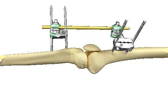
5 Technical details MRI information Hoffmann 3 Modular External Fixation devices are labeled MR conditional according to the terminology specified in ASTM F2503, standard practice for marking medical devices and other items for safety in the magnetic resonance environment. Non-clinical testing* has demonstrated that the Hoffmann 3 Modular External Fixation System is MR conditional. A patient with a Hoffmann 3 Modular External Fixation Frame may be safely scanned under the following conditions: Static magnetic field of 1.5 Tesla ONLY Spatial magnetic field gradient 900 gauss / cm (90mT / cm) or less Maximum MR system reported whole body averaged specific absorption rate (sar) of 2 w / kg for 15 minutes of scanning time under normal operating mode The Hoffmann 3 system must be outside the MRI scanner bore. (See diagram for example). Under such conditions, the maximal expected temperature rise is less than 6 C. Note: In non-clinical testing, all Hoffmann 3 Modular External Fixation frame configurations shown in this operative technique have been tested under the above mentioned conditions. The MR field conditions should be compared with those of the user s MR system, to determine if the Hoffmann 3 device can be safely brought into the user s MR environment. All components of Hoffmann 3 frames must be identified as MR conditional prior to being placed in or near an MR environment. Because higher in vivo heating cannot be excluded, close patient monitoring and communication with the patient during the scan is required. Immediately abort the scan if the patient reports burning sensation or pain. To minimize heating, the SAR should be as low as possible, and the scan time should be as short as possible. The Hoffmann 3 devices must be placed outside of the magnet bore for all scans. Under no circumstance must the Hoffmann 3 be exposed to the RF field of the body coil or the RF field on a RF transmitting local coil. Please refer to the pictorial representation on the next page showing the allowable position of the Hoffmann 3 frames in the MR scanner environment. All tested frames are safe with respect to displacement in MRI magnetic field of 1.5 Tesla only and a spatial magnetic field gradient of up to 90mT / cm. Patient safety MRI for patients with Hoffmann 3 External Fixation System can only be performed under these parameters. Using other parameters could result in serious injury to the patient. Use of Hoffmann 3 with other Hoffmann systems has not been tested in the MR environment and therefore there may be a risk of higher heating and serious injury to the patient. Do not place any RF transmitting coils over the Hoffmann 3 External Fixation Frame. * Based upon Biomechanical Lab Report: BML , Stryker in Selzach, Switzerland BML , BML , BML


 Hoffmann 3 (example) 8 Do not use the Hoffmann 3 partially in the")
6 Technical details Artifact information MR image quality may be compromised if the area of interest is close to the Hoffmann 3 Frame components. It may be necessary to optimize MR imaging parameters to compensate for the presence of the fixation frame. Representative Hoffmann 3 components have been evaluated in the MRI chamber according to ASTM F2119 and worst-case artifacts will extend approximately 10cm from the device for the following sequences: Gradient echo sequence: TR 100ms, TE 15ms, flip angle 30, Resolution 1 x 1 x 3mm 3, scan matrix 256 x 256, bandwidth per pixel 125Hz Spin echo sequence: TR 500ms, TE 20ms, flip angle 70, resolution 1 x 1 x 3mm 3, scan matrix 256 x 256, bandwidth per pixel 125Hz Position of Hoffmann 3 frames in the MR environment: Entire construct should be visible outside the magnet bore Outside the bore of the magnet of the MR Scanner Bore of the magnet of the MR Scanner Hoffmann 3 (example) 4 Correct placement of the Hoffmann 3 outside the magnet bore of the MR scanner Incorrect placement of the Hoffmann 3 in the MR environment: Partially in the magnet bore of the MR scanner Completely within the magnet bore of the MR scanner Hoffmann 3 (example) Hoffmann 3 (example) 8 Do not use the Hoffmann 3 partially in the magnet bore of the MR scanner Do not use the Hoffmann 3 in the magnet bore of the MR scanner 8 6


7 Components Delta couplings Delta coupling, rod-to-rod or pin-to-rod The rod-to-rod delta couplings can snap onto Ø5, Ø8 or Ø11mm connecting rods and Ø5mm Apex pins**. Rod-to-rod delta couplings are color coded green / green. Delta coupling, pin-to-rod The pin-to-rod delta couplings are designed to fit Ø5, Ø8 or Ø11mm connecting rods and Ø4, Ø5 or Ø6mm Apex pins. Pin-to-rod delta couplings are color coded grey / green. Delta coupling, pin-to-rod, inverted Inverted pin-to-rod delta coupling are available with the bolt on the opposite side. Inverted pin-to-rod delta couplings are color coded green / grey. ** Note: Standardization with one coupling may be achieved by utilizing a rod-to-rod delta coupling with Ø8mm or Ø11mm connecting rod and 5mm apex pins or 3 / 5mm, 4 / 5mm hybrid Apex pins. 7


8 Components Delta couplings Delta coupling, rod-to-rod, multiplanar The multiplanar rod-to-rod delta coupling is designed to snap onto Ø5, Ø8 or Ø11mm connecting rods and / or Ø5mm Apex pins on each side of the joint. The multiplanar joint allows for 180 º of motion and 360 º of rotation. Multiplanar delta couplings are color coded green / green and include two pre-assembled thumbwheels for provisional tightening. Delta coupling, pin-to-rod, multiplanar The multiplanar pin-to-rod delta coupling is designed to snap onto Ø5, Ø8 or Ø11mm connecting rods and Ø4, Ø5 or Ø6mm Apex pins on each side of the joint. The multiplanar joint allows for 180 º of motion and 360 º of rotation. Multiplanar delta couplings, pin-to-rod are color coded grey / green and include two pre-assembled thumbwheels for provisional tightening. Multiplanar delta couplings can be tightened on one side while keeping full rotational flexibility and adjustability on the other side. The distance between the bars or pins can be varied from 0mm to 37mm. 8


 or")
9 Components Provisional tightening Step 1 Snap two rods (or a pin and a rod) into a delta coupling. Step 2 Provisionally tighten the coupling to the rods using the thumbwheel. Step 1 Step 2 Step 3 Remove the thumbwheel from the delta coupling before the final tightening. Final Tightening For final tightening use either the T-handle ( ) or 7mm spanner wrench ( ). Step 3 9


10 Components 5-Hole pin clamp 5-Hole pin clamps can be used if parallel pin placement is desired. The clamp can hold up to five Apex half pins, accommodating Ø4, Ø5 or Ø6mm pins. Screws for locking the posts in place Pin clamps are secured to the Apex pins by tightening the 7mm square head screws on the side of the clamp Screws for securing clamps to the Apex pins Posts Straight, 30 or 90 angled Ø11mm posts are used along with the pin clamps to provide a compact, fracture-specific frame. Posts are locked into place by tightening the two 7mm square head screws on the top of the clamp NOTICE Tightening of the nuts for locking the posts without any posts in the hole can deform the 5 hole pin clamps and therefore limit its functionality. 10


11 Components Fixed post clamps 5-Hole pin clamps with either one or two straight or 30 angled fixed posts are included in the Hoffmann 3 system for multiple ready-to-use configurations that don t require assembly. Ø11mm Connecting rods Electrically insulated vectran coated carbon fiber rods are provided for MR conditional use in 1.5 tesla systems according to the specified conditions. The Ø11mm vectran coated carbon fiber connecting rods are available in lengths from 100mm to 650mm. The Ø11mm vectran coated semicircular rod is available in 220mm size, and may be used for the fixation of distal femur or proximal tibia fragments. Carbon fiber rods are designated as single use. Carbon fiber rods are designated as single use. Tests have shown intended performance for 50 re-sterilization cycles.* A variety of Ø8mm and Ø5mm vectran coated carbon fiber rods are available in the Hoffmann II MRI and Hoffmann II MRI Compact ystemand are compatible with Hoffmann 3. Note: Testing has demonstrated intended performance of the carbon fiber rods for 50 re-sterilization cycles.* * Biomechanical Test Reports: BML , BML


12 Components Rod coupler, 30 Rod Couplers connect two, 11mm connecting rods at a fixed 30 angle in a symmetric or asymmetric orientation and are used in building spanning frames such as knee bridging and pelvis. The asymmetric capability allows the coupler to aid in fracture reduction and is designed for fine tuning of rod length to more closely match patient anatomy. The coupler is designed with a window that allows for visual control of rod depth in the clamping area. 12

13 Components Apex pin Four types of half pins are offered in the system: blunt / self-tapping half pins, blunt / cancellous half pins, self-drilling / self-tapping half pins, and self-drilling transfixing pins. Pre-drilling is necessary when using blunt pins. It is optional to pre-drill when using self-drilling pins. General guidelines for pre-drilling Always pre-drill with a new, sharp drill Drill slowly to help prevent thermal injury When placed through an exposed bone surface irrigating the interface can reduce heating Always use the appropriate sized drill bit based on pin diameter. Self-drilling pin Cancellous pin Blunt pin Transfixing pin Additional options Stainless steel with HA coated options Titanium Sterile and non sterile packaging Hybrid Apex pins with 3mm thread diameter and 5mm shaft, as well as 4mm thread diameter and 5mm shaft Note: For additional information please refer to the Apex Pin Operative Technique. Content ID: APEX-ST-1. Pin thread diameter Drill bit Location Ø3mm Ø2.2mm Ulna, radius, wrist, metacarpal ø4mm ø5mm ø6mm Ø3.2mm Ø3.5mm Ø4.0mm Ø4.5mm Ø4.5mm Ø5.0mm Radius, ulna, humerus, tibia, metatarsal Tibia, femur, calcaneus, pelvis Adult tibia, femur, pelvis 13

 and can be used for small bone fixation without opening a small")


14 Components Hybrid Apex pins Designed with Ø3mm or Ø4mm threads while maintaining a Ø5mm shaft. Hybrid Apex pins are compatible with rod-to-rod delta couplings (Ø5mm side) and can be used for small bone fixation without opening a small external fixation set. Hybrid pins are compatible with the universal pin chuck which may increase intra-operative efficiency. Universal pin chuck The Universal Pin Chuck with AO coupling accommodates Ø4, Ø5, and Ø6mm diameter Apex pins. Use of this instrument may remove the need for multiple chucks for different half pin diameters. 14


15 Tibial frames Pin technique / safe zones Knowledge of the cross-sectional anatomy of the tibia helps to ensure safe pin placement. Apex half pins can be placed in the medial face of the tibia from plateau to pilon Transfixing pins can be safely placed except in the distal third of the tibia proximal to the metaphysis and distal to the fibula head near the peroneal nerve Before insertion of anterior Apex half pins near the ankle joint, perform blunt dissection to bone to ensure safety of neurovascular bundle Cut A. Superficial peroneal nerve Deep peroneal nerve Cut B. Anterior tibial artery Cut C. Cut A. Cut B. Cut C. 15

16 Tibial frames Tibial standard bi-lateral frame Parallel pin placement Components list Ref Description Quantity Hole pin clamp Angled post Ø11mm Rod-to-rod delta coupling Apex pin Ø5mm x 150mm Connecting rod Ø11mm x 300mm 2 Note: Alternatively the pin-to-rod delta couplings can be replaced by mulitplanar pin-to-rod delta couplings, thus offering more flexibility and freedom when placing Apex pins and when reducing the fracture before final tightening. 16


17 Tibial frames Tibial single rod frame Independent pin placement, with multiplanar delta couplings Components list Ref Description Quantity Pin-to-rod delta coupling, multiplanar Pin-to-rod delta coupling Apex pin Ø5mm x 150mm Connecting rod Ø11mm x 300mm 1 17
18 Tibial frames Tibial standard osteotaxis half frame Parallel pin placement Components list Ref Description Quantity Hole pin clamp Angled post Ø11mm Rod-to-rod delta coupling Apex pin Ø5mm x 150mm Connecting rod Ø11mm x 300mm 1 18


19 Tibial frames Tibial plateau semi-circular frame Parallel / independent pin placement Components list Ref Description Quantity Hole pin clamp Angled post Ø11mm Rod-to-rod delta coupling Pin-to-rod delta coupling Pin-to-rod delta coupling, inverted Apex pin Ø5mm x 150mm Semi circular rod Ø11mm x 220mm Connecting rod Ø11mm x 300mm 3 19
20 Tibial frames Distal tibia shaft frame Parallel / independent pin placement Components list Ref Description Quantity Hole pin clamp Angled post Ø11mm Rod-to-rod delta coupling Pin-to-rod delta coupling Apex pin Ø5mm x 150mm Connecting rod Ø11mm x 250mm 2 20


21 Ankle frames Pin technique / safe zones Knowledge of the cross-sectional anatomy of the ankle helps to ensure safe pin placement. Apex half pins can be placed proximal to the ankle from medial to lateral in the anteromedial face of the tibia Apex pins can be placed distal to the crossing of the anterior tibial vessels just proximal to the ankle Before insertion of anterior Apex half pins near ankle joint, perform blunt dissection to bone to ensure safety of neurovascular bundle Hybrid pins can be placed from the medial or dorsomedial side 0-115º from the frontal plane Transfixing pins can be placed through the calcaneus from medial to lateral Cut A. Cut A. 21


22 Ankle frames Ankle delta frame Parallel pin placement / semi-circular rod used as a kick-stand / foot stabilizing Ø3 / 5mm hybrid Apex pin Components list Ref Description Quantity Transfixing pin Ø5mm / Ø6mm, Ø300mm x Ø40mm Apex pin Ø5 x Ø150mm Self-drilling hybrid half pin Apex Ø3 / Ø5mm, Ø120 x Ø20mm Rod-to-rod delta coupling Hole pin clamp Angled posts Ø11mm Semi circular rod Ø11 x Ø220mm Connecting rod Ø11 x Ø350mm Connecting rod Ø11 x Ø200mm 1 Note: Alternatively the 5-hole pin clamp with posts can be replaced by a pre-welded 5-hole pin clamp with fixed posts (Ref ). 22

.")
23 Ankle frames Ankle bridging frame Parallel pin placement Components list Ref Description Quantity Apex pin Ø5mm x Ø150mm Transfixing pin Ø5mm / Ø4mm x Ø200mm Rod-to-rod coupling Hole pin clamp Straight post Ø11mm Angled post Ø11mm Connecting rod Ø11mm x Ø250mm 2 Note: Alternatively the 5-hole pin clamp with straight posts can be replaced by a pre-welded 5-hole pin clamp with fixed posts (Ref ). Alternatively to the Ø4mm transfixing pin with Ø5mm thread we recommend the Ø5mm transfixing pin 300mm x 40mm with Ø6mm thread (Ref ). 23

24 Femur frames Pin technique / safe zones Knowledge of the cross-sectional anatomy of the femur helps to ensure safe pin placement. Apex half pins can be placed in the femur from lateral to medial along the entire length of the bone Transfixing pins can be placed in the distal quarter of the femur distal to the passage of the femoral artery posteriorly Cut A. Cut B. Cut C. Cut A. Cut B. Cut C. 24
25 Femur frames Femur emergency frame Independent pin placement Components list Ref Description Quantity Pin-to-rod delta coupling Rod-to-rod delta coupling Apex pin Ø6mm x 180mm Connecting rod Ø11mm x 350mm 3 Note: Apply additional pins and rods before patient transportation. 25


26 Knee frames Pin technique / safe zones Apex half pins can be placed anterolaterally in the femur, and anteromedially in the tibia. 26


27 Knee frames Knee bridging frame Independent pin placement, with rod coupler Components list Ref Description Quantity Pin-to-rod delta coupling Apex pin Ø5mm x 180mm Rod coupler, Connecting rod Ø11mm x 450mm Connecting rod Ø11mm x 350mm 1 Note: Alternatively pin-to-rod delta couplings can be replaced by mulitplanar pin-to-rod delta couplings, thus offering more flexibility and freedom when placing Apex pins. A rod-to-rod delta coupling could also be used in place of a rod coupler. 27
28 Knee frames Knee bridging frame Independent pin placement Components list Ref Description Quantity Pin-to-rod delta coupling Rod-to-rod delta coupling Apex pin Ø6mm x 180mm Apex pin Ø5mm x 180mm Connecting rod Ø11mm x 350mm Connecting rod Ø11mm x 200mm 1 28


29 Knee frames Knee bridging z-frame Independent pin placement, with rod coupler Components list Ref Description Quantity Pin-to-rod delta coupling Rod-to-rod delta coupling Apex pin Ø5mm x 180mm Rod coupler, Connecting rod Ø11mm x 400mm Connecting rod Ø11mm x 250mm 1 Note: Alternatively pin-to-rod delta couplings can be replaced by mulitplanar pin-to-rod delta couplings, thus offering more flexibility and freedom when placing Apex pins. A rod-to-rod delta coupling could also be used in place of a rod coupler. 29

30 Pelvic frames Pin technique / safe zones Knowledge of the cross-sectional anatomy of the pelvis helps to ensure safe pin placement. Apex half pins can be placed in the iliac wings Apex half pins can be placed in the pelvis in the crest between the anterior-superior and anterior inferior iliac spines 30

31 Pelvic frames Pelvic osteotaxis frame Independent iliac crest pin placement Components list Ref Description Quantity Pin-to-rod delta coupling, inverted Rod-to-rod delta coupling Apex pin Ø5mm x 200mm Connecting rod Ø11mm x 350mm Connecting rod Ø11mm x 150mm 2 31


32 Pelvic frames Pelvic osteotaxis frame Independent iliac crest pin placement, with rod coupler Components list Ref Description Quantity Pin-to-rod delta coupling, inverted Rod-to-rod delta coupling Rod coupler, Connecting rod Ø11mm x 150mm Connecting rod Ø11mm x 250mm Apex pin Ø5 x 180mm 4 32

33 Pelvic frames Pelvic orthogonal frame construct Perpendicular iliac crest / supra-acetabular pin placement Components list Ref Description Quantity Pin-to-rod coupling Rod-to-rod coupling Apex pin Ø5mm x 200mm Connecting rod Ø11mm x 350mm Connecting rod Ø11mm x 150mm Connecting rod Ø11mm x 400mm 1 33
 and Ø11mm vectran coated carbon fiber connecting rods for the temporary")
34 Military or disaster recovery kits Vision, global engineering, Swiss manufacturing The Hoffmann 3 Sterile Field Kits A and B contain scalpels, mosquito clamps, self-drilling Apex pins, a manual drill-brace for pin insertion and frame tightening, Hoffmann 3 Delta Couplings (Kit A also includes 5-hole pin clamps) and Ø11mm vectran coated carbon fiber connecting rods for the temporary stabilization of diverse fracture patterns. Sterile Field Kit A Ref: S Sterile Field Kit B Ref: S 34
35 Sterile field kit A Femoral safe zone Between anterolateral and lateral sites Antero-lateral Distal from the greater trochanter to 3-4 fingers proximal to patella Lateral Distal from the greater trochanter to 1-2 fingers proximal to knee joint Tibial Safe Zone Medial 1-2 fingers distal to knee joint avoiding patella tendon and tibial tubercle 1 finger proximal to ankle 35

36 Sterile field kit A Hoffmann 3 Sterile Field Kit A application technique: Step 1: Provisionally reduce and align the limb. Apply self drilling, self tapping Apex pins through 1cm linear incision of the soft tissue made down to the bone with the scalpel. The included hemostat clamp may be used to spread soft tissues before pin insertion. Step 2: Pins are placed through both cortices using the black brace, pin end, as shown. Step 3: Insert the first pin 2-3 finger breadth proximal to the fracture / bone defect (Fig. 1)*. Note: In emergency situations often there is no X-ray (fluoroscopy) available. Under such circumstances it is not possible to localize the fracture site accurately. Therefore, it is recommended to place the Apex pins in an area which is in a safe distance proximally and distally from the fracture site. Fig. 1 Step 4 The insertion point of the Apex pin in the first cortex should be positioned exactly in the center of the cross-section of the bone to avoid excentric or tangential positioning (Fig. 2). After penetration of the first cortex, a drop in resistance will be detected. Using light pressure, insertion of the pin is continued. Once firm resistance of the second cortex is felt, six complete revolutions of the drill brace will put the pin tip through the second cortex (Fig. 2). Fig. 2 36
.")

37 Sterile field kit A Step 5: Place 5-hole pin clamp over first Apex pin, using the widest placement possible. Keep the clamp screws facing up and out (medial), as shown (Fig. 3). As mentioned above: keep safe distance from the fracture site. Step 6: Insert second proximal pin maintaining parallel alignment with the first pin, using the clamp as a guide (Fig. 4). Step 7: Repeat the process for the two distal pins, keeping the pins parallel and at least two finger breadth away from the fracture / bone defect (Fig. 5). Step 8: In the next step attach the rod-torod delta couplings with the connecting rod. With frame in place and fracture reduced, fully tighten all nuts, using the drill brace end marked clamp. In case the frame is not used in the pre-assembled manner, use the following instructions to assemble the frame. Fig. 3 Fig. 4 Fig. 5 37

. Fig.")
. Fig.")
. Fig.")

38 Sterile field kit A Step 9: Attach the delta rod-to-rod couplings as shown. Use care to avoid the 30 bend area when tightening the couplings onto the posts (Fig. 6). Fig. 6 Step 10: Snap a connecting rod to the coupling. Provisionally tighten using the thumbwheel (Fig. 7). Fig. 7 Step 11: Remove the thumbwheel from the rod-to-rod coupling to prepare for final tightening (Fig. 8). Fig. 8 Step 12: Use the clamp end of the brace for final tightening while maintaining reduction and alignment of the limb. Repeat for all clamps and couplings (Fig. 9). Fig. 9 38


39 Sterile field kit A Tibial frame example (With Ø11mm connecting rod, Ø5mm Apex pins). Femoral frame example (With Ø11mm connecting rod, Ø5mm Apex pins). Knee bridge frame example (With Ø11mm connecting rod, Ø5mm Apex pins). Wrist bridge frame example (With Ø8mm connecting rod, Ø3 / Ø5mm Apex pins). 39


40 Sterile field kit B Femoral safe zone Between anterolateral and lateral sites. Antero-lateral Distal from the greater trochanter to 3-4 fingers proximal to patella. Lateral Distal from the greater trochanter to 1-2 fingers proximal to knee joint. Tibial safe zone Medial 1-2 Fingers distal to knee joint avoiding patella tendon and tibial tubercle 1 finger proximal to ankle. Pin placement for pelvic emergency frame; pin technique / safe zones Pins can be placed percutaneously in the iliac wings or in the crest between the anterior-superior and anterior-inferior iliac spines. 40

. Pin end Step 3: Insert the first pin 2-3 finger breadth away from the fracture / bone defect (Fig 1)*. Fig.")
41 Sterile field kit B Step 1: Provisionally reduce and align the limbs. Apply self drilling, self tapping Apex pins by inserting through 1cm linear incision of the soft tissue made down to the bone with the scalpel. The included hemostat clamp may be used to spread soft tissue before pin insertion. Step 2: Attach the delta rod-to-rod couplings as shown. Use care to avoid the 30 bend area when tightening the couplings onto the posts (Fig. 6). Pin end Step 3: Insert the first pin 2-3 finger breadth away from the fracture / bone defect (Fig 1)*. Fig. 1 *Note: In emergency situations often there is no X-ray (fluoroscopy) available. Under such circumstances it is not possible to localize the fracture site accurately. Therefore, it is recommended to place the apex pins in an area which is in a safe distance from the fracture site. Fig. 2 41
. After penetration of the first cortex, a drop in resistance will be detected. Using light pressure, insertion of the pin is continued.")
.")
42 Sterile field kit B Step 4: The insertion point of the Apex pin in the first cortex should be positioned exactly in the center of the crosssection of the bone to avoid excentric or tangential positioning (Fig. 2). After penetration of the first cortex, a drop in resistance will be detected. Using light pressure, insertion of the pin is continued. Once firm resistance of the second cortex is felt, six complete revolutions of the drill brace will put the pin tip through the second cortex (Fig 2). Step 5: Place second pin in the same limb / fragment. (Fig 3). Note: The larger the distance between these two pins the more stable the construct will be** Step 6: Attach one delta coupling to each pin*** Fig. 3 Fig. 4 ** Gernot Asche, Wolfgang Roth, Ludwig Schroeder (eds.): The External Fixator - standard indications, operating instructions and examples of frame configurations; Markus Behrens: The mechanics and stability of fixator components. Page 32 ff. *** For increased stability follow the «rule of thumb»: «In» «Up», meaning the delta couplings shall be «in» between the pins, the black thumbwheels looking «up» so that one has access to them for easy tightening. 42


.")

43 Sterile field kit B Step 7: Attach a connecting bar to the delta couplings (Fig 5). Provisionally tighten the delta couplings using the built-in black thumbwheels by hand (Fig. 6). Step 8: Repeat this in the other limb and connect the two frames with 2 more couplings and a third bar to achieve a z-frame here shown as a knee-bridging frame (Fig. 7). Before final tightening reduce and align the limbs as shown (Fig. 7). Step 9: For final tightening remove the black thumbwheel from the coupling (Fig. 8). Step 10: Use the clamp end of the brace for final tightening while maintaining reduction and alignment of the limbs. Repeat for all delta couplings (Fig. 9). Fig. 5 Fig. 6 Fig. 7 Fig. 8 Fig. 9 43


44 Sterile field kit B Knee bridging frame example Pelvic emergency frame example 44
45 Notes: 45
46 Notes: 46
47 Notes: 47
48 This document is intended solely for the use of healthcare professionals. A surgeon must always rely on his or her own professional clinical judgment when deciding whether to use a particular product when treating a particular patient. Stryker does not dispense medical advice and recommends that surgeons be trained in the use of any particular product before using it in surgery. The information presented is intended to demonstrate a Stryker product. A surgeon must always refer to the package insert, product label and/or instructions for use, including the instructions for cleaning and sterilization (if applicable), before using any Stryker product. Products may not be available in all markets because product availability is subject to the regulatory and/or medical practices in individual markets. Please contact your Stryker representative if you have questions about the availability of Stryker products in your area. Manufacturer: Stryker GmbH Bohnackerweg Selzach Switzerland stryker.com Stryker Corporation or its divisions or other corporate affiliated entities own, use or have applied for the following trademarks or service marks: Apex, Hoffmann, Stryker. All other trademarks are trademarks of their respective owners or holders. This document is only approved for use in the USA. The corresponding OUS version is H-ST-32. Content ID: H-ST-20_Rev-2, Copyright 2018 Stryker
Hoffmann II External Fixation System
 Hoffmann II External Fixation System Modular System for Long Bones Pelvis Introduction In 1938, Raoul Hoffmann, a surgeon from Geneva, Switzerland, designed a revolutionary External Fixation System. The
Medium External Fixator Humeral Shaft Frame. Modular frame for upper extremity use.
 Medium External Fixator Humeral Shaft Frame. Modular frame for upper extremity use. Technique Guide Part of the Medium External Fixation System MRI Information Synthes Medium External Fixation devices
EasyStep. Operative technique
 Operative technique EasyStep - Step staple This publication sets forth detailed recommended procedures for using Stryker Osteosynthesis devices and instruments. It offers guidance that you should heed,
Medium External Fixator Pediatric Femoral Shaft Frame. Using medium multi-pin clamps.
 Medium External Fixator Pediatric Femoral Shaft Frame. Using medium multi-pin clamps. Technique Guide Part of the Medium External Fixation System MRI Information Synthes Medium External Fixation devices
Hoffmann II MRI External Fixation Systems. Hoffmann II MRI Hoffmann II Compact MRI Modular Systems for Upper Extremity Lower Extremity Pelvis
 Hoffmann II MRI External Fixation Systems Hoffmann II MRI Hoffmann II Compact MRI Modular Systems for Upper Extremity Lower Extremity Pelvis Introduction In the ever changing world of medicine, new technology
Low-Profile Wrist Fixator. For stabilization of fractures of the distal radius.
 Low-Profile Wrist Fixator. For stabilization of fractures of the distal radius. Technique Guide Part of the External Fixation System Low-Profile Wrist Fixator Indications Intended for stabilization of
Hoffmann II Compact External Fixation System. Modular System for
 Hoffmann II Compact External Fixation System Modular System for Introduction In 1938, Raoul Hoffmann, a surgeon from Geneva, Switzerland, designed a revolutionary External Fixation System. The basic features
External Distal Radius Fixator. Supplement to the 8 mm rod fixator system
 External Distal Radius Fixator. Supplement to the 8 mm rod fixator system Surgical technique This publication is not intended for distribution in the USA. Instruments and implants approved by the AO Foundation
Large External Fixator Delta Frame Ankle Bridge. For staged fixation of the distal tibia.
 Large External Fixator Delta Frame Ankle Bridge. For staged fixation of the distal tibia. Technique Guide Part of the Large External Fixation System Large External Fixator Delta Frame Ankle Bridge Technique
For Small-Statured Adults and Pediatric Patients. Medium External Fixator Basic Modular Frame
 For Small-Statured Adults and Pediatric Patients Medium External Fixator Basic Modular Frame Surgical Technique MRI Information DePuy Synthes Medium External Fixation devices are labeled MR Conditional
Large External Fixator Delta Frame Ankle Bridge. Using pin clamps with outrigger posts.
 Large External Fixator Delta Frame Ankle Bridge. Using pin clamps with outrigger posts. Technique Guide Part of the Large External Fixation System Large External Fixator Delta Frame Ankle Bridge Technique
Large External Fixator Modular Knee Bridge
 Using Multi-pin Clamps Large External Fixator Modular Knee Bridge Surgical Technique Large External Fixator Modular Knee Bridge DePuy Synthes Large External Fixation devices are labeled MR Conditional
Hoffmann II Compact External Fixation System
 Trauma Hoffmann II Compact External Fixation System Modular System for Upper Extremity Foot Introduction In 1938, Raoul Hoffmann, a surgeon from Geneva, Switzerland, designed a revolutionary External Fixation
Large External Fixator Modular Knee Bridge. Using multi-pin clamps.
 Large External Fixator Modular Knee Bridge. Using multi-pin clamps. Technique Guide Part of the Large External Fixation System Large External Fixator Modular Knee Bridge Technique Overview Insert Schanz
Hoffmann II Micro External Fixation System
 Trauma Hoffmann II Micro External Fixation System Indications for the Hand Components 9 3 4 5 1 2 7 8 6 1 Hoffmann II Micro Multi-Pin Clamp 2 Hoffmann II Micro 90 Multi-Pin Clamp 3 Hoffmann II Micro Rod
Medium External Fixator Delta Frame Ankle Bridge
 For Small-Statured Adults Medium External Fixator Delta Frame Ankle Bridge Surgical Technique MRI Information DePuy Synthes Medium External Fixation devices are labeled MR Conditional according to the
Hoffmann II Micro External Fixation System. Indications for the Hand
 Hoffmann II Micro External Fixation System Indications for the Hand Features & Benefits The instrumentation is Simple and User-Friendly, and the system is Color Coded, so there is no lost time or confusion
CableFIX Xpress Carpometacarpal Fixation System. Operative technique
 CableFIX Xpress Carpometacarpal Fixation System Operative technique CableFIX Xpress Carpometacarpal Fixation System CableFIX Xpress Carpometacarpal Fixation System Contents 1. Indications and contraindications...
Asnis. Micro Cannulated screw system. Xpress operative technique
 Asnis Micro Cannulated screw system Xpress operative technique Asnis Micro Cannulated screw system Table of contents Indications, precautions & contraindications 3 Operative technique 4 This publication
VariAx Compression Plating System. Operative technique
 VariAx Compression Plating System Operative technique VariAx Compression Plating System Operative technique VariAx Compression Plating System Contents 1. Introduction... 3 2. Indications, MR safety information
Asnis III Cannulated Screw System. Operative technique
 Asnis III Cannulated Screw System Operative technique Asnis III Cannulated Screws Operative technique Asnis III Cannulated Screw System Contents 1. Indications and contraindications... 4 2. Technical specifications...
Foot & Ankle. Smart Toe II. Intramedullary Implant. Operative Technique. Foot & Ankle
 Foot & Ankle Smart Toe II Intramedullary Implant Operative Technique Foot & Ankle Smart Toe This publication sets forth detailed recommended procedures for using Stryker Osteosynthesis devices and instruments.
4Fusion. Shape Memory Implant. Operative Technique
 4Fusion Shape Memory Implant Operative Technique 4Fusion This publication sets forth detailed recommended procedures for using Stryker devices and instruments. It offers guidance that you should heed,
Sterile-Packaged Large External Fixator Kits. For treatment of long bone and pelvic fractures that require external fixation.
 Sterile-Packaged Large External Fixator Kits. For treatment of long bone and pelvic fractures that require external fixation. Large External Fixator Ankle Frame Kit Large External Fixator Trauma Kit Large
AxSOS. Locking Plate System. Operative Technique. Small Fragment Basic Fragment
 AxSOS Locking Plate System Operative Technique Small Fragment Basic Fragment Stryker Plating Contents Page 1. Introduction 4 2. Features & Benefits 5 4 and 5 Compression Plates 5 Reconstruction and 1/3
Monotube Triax. External Fixation System. External Fixation. Operative Technique
 Monotube Triax External Fixation System Operative Technique External Fixation 1 Monotube Triax This publication sets forth detailed recommended procedures for using Stryker Osteosynthesis devices and instruments.
EXTERNAL FIXATION SYSTEM
 EXTERNAL FIXATION SYSTEM 2 3 1 4 5 1. DJD II Body 2. Humeral Guide 3. Pin Insertion Guides 4. Hoffmann II Compact Instruments 5. Hoffmann II Compact Components and Apex Pins 2 Overview The DJD II is a
AxSOS Locking Plate System
 AxSOS Locking Plate System Operative Technique Small Fragment Basic Fragment 1 2 Contents Page 1. Introduction 4 2. Features & Benefits 5 4 and 5mm Compression Plates 5 Reconstruction and 1/3 Tubular Locking
Knee spanning solutions
 Knee spanning solutions System features Indications Intended to be used on adults or pediatric patients as required for fracture fixation (open or closed); post-traumatic joint contracture which has resulted
MEFiSTO. Monolateral External Fixation System for Trauma and Orthopaedics.
 MEFiSTO. Monolateral External Fixation System for Trauma and Orthopaedics. Surgical Technique This publication is not intended for distribution in the USA. Instruments and implants approved by the AO Foundation.
Hoffmann LRF Circular External Fixation. Operative technique
 Hoffmann LRF Circular External Fixation Operative technique Hoffmann LRF Circular External Fixation Operative technique Hoffmann LRF Circular External Fixation Contents 1. Indications and contraindications...
Foot & Ankle. EasyClip. Osteosynthesis Compression Staples. Foot & Ankle
 Foot & Ankle EasyClip Osteosynthesis Compression Staples Foot & Ankle Operative Technique EasyClip Osteosynthesis Compression Staples 2 This publication sets forth detailed recommended procedures for using
Large External Fixator Traveling Traction
 Used to Correct Angular Deformity Large External Fixator Traveling Traction Surgical Technique Large External Fixator Traveling Traction DePuy Synthes Large External Fixation devices are labeled MR Conditional
Surgical Technique. Distal Radius and Foot
 Surgical Technique Distal Radius and Foot JET-X BAR Unilateral Fixator Distal Radius and Foot Surgical Technique Contents Design Features...2 Distal Radius Surgical Technique Indications...10 Surgical
FastFrame External Fixation System. Damage Control Surgical Technique
 FastFrame External Fixation System Damage Control Surgical Technique 1 FastFrame External Fixation System Damage Control Surgical Technique Table of Contents Introduction... 2 Indications and Contradictions...
AxSOS 3 Titanium Proximal Lateral Tibia Locking Plate System. Operative technique Targeting instrumentation
 AxSOS 3 Titanium Proximal Lateral Tibia Locking Plate System Operative technique Targeting instrumentation AxSOS 3 Titanium Operative technique AxSOS 3 Titanium Proximal Lateral Tibia Locking Plate System
The Calcaneal Plate. The Synthes non-locking solution for the Calcaneus.
 The Calcaneal Plate. The Synthes non-locking solution for the Calcaneus. Surgical Technique This publication is not intended for distribution in the USA. Instruments and implants approved by the AO Foundation.
Small External Fixator Nonspanning Wrist Frame. For the treatment of wrist fractures.
 Small External Fixator Nonspanning Wrist Frame. For the treatment of wrist fractures. Technique Guide Part of the Small External Fixation System Small External Fixator Nonspanning Wrist Frame When to use
EXTERNAL FIXATION SYSTEM
 EXTERNAL FIXATION SYSTEM The Apex Pin Fixation System is a one step procedure reducing insertion time and reducing insertion temperature. There are three types of fixation pins: Self-drilling / Self-tapping
TransFx External Fixation System Large and Intermediate Surgical Technique
 TransFx External Fixation System Large and Intermediate Surgical Technique TransFx External Fixation System Large and Intermediate Surgical Technique 1 Surgical Technique For TransFx External Fixation
Femur. Monoaxial Locking Plate System. Operative Technique. Distal Lateral Femur Universal Holes Targeting Instrumentation.
 Femur AxSOS 3 Titanium Monoaxial Locking Plate System Femur Fractures Operative Technique Distal Lateral Femur Universal Holes Targeting Instrumentation This publication sets forth detailed recommended
Gamma3 TM Fragment Control Clip
 Osteosynthesis Gamma3 TM Fragment Control Clip Operative Technique Hip Fracture Introduction Indication The Fragment Control Clip is designed to stabilize rotationally unstable femoral head-neck fragments
3. PATIENT POSITIONING & FRACTURE REDUCTION 3 8. DISTAL GUIDED LOCKING FOR PROXIMAL NAIL PROXIMAL LOCKING FOR LONG NAIL 13
 Contents IMPLANT FEATURES 2 1. INDICATIONS 3 2. PRE-OPERATIVE PLANNING 3 3. PATIENT POSITIONING & FRACTURE REDUCTION 3 4. INCISION 4 5. ENTRY POINT 4-6 6. PROXIMAL NAIL INSERTION 6-7 7. PROXIMAL LOCKING
Asnis III. Cannulated Screw System. Operative Technique. 4.0mm 5.0mm 6.5/8.0mm. Shoulder. Elbow. Hand & Wrist. Hip. Pelvis. Femur.
 Shoulder Elbow Asnis III Cannulated Screw System Hand & Wrist Operative Technique 4.0mm 5.0mm 6.5/8.0mm Hip Pelvis Femur Tibia & Fibula Foot & Ankle Asnis III Cannulated Screws Content This publication
EBI FIX DYNAFIX SYSTEM VISION EXTERNAL FIXATION SURGICAL TECHNIQUE. Patent 6,277,119
 EBI DYNAFIX FIX SYSTEM DYNAFIX VISION EXTERNAL FIXATION SYSTEM SURGICAL TECHNIQUE Patent 6,277,119 1 CONTENTS Basic Principles and Biomechanical Concepts...Page 2 Introduction...Page 2 Component Review...
Large Distractor Femur
 Fracture Reduction and Provisional Stabilization Large Distractor Femur Surgical Technique Table of Contents Introduction Standard Femoral Distraction 2 Large Distractor System 4 Surgical Technique Prepare
Imbibe Bone marrow aspiration needle. Operative technique
 Imbibe Bone marrow aspiration needle Operative technique Imbibe Bone Marrow Aspiration Needle Imbibe Bone marrow aspiration needle Contents 1. Smart design... 3 2. Operative technique... 4 Posterior iliac
PAL Pelvic Alignment Level
 PAL Pelvic Alignment Level Surgical Protocol For consistency during surgery Pelvic Alignment Level (PAL) Features Pelvic Alignment Level Surgical Protocol To Table To Floor 1. Patient Positioning & Preparation
System. Humeral Nail. Surgical Technique
 System Humeral Nail Surgical Technique Contents IMPLANT FEATURES 2 1. INDICATIONS 3 2. PRE-OPERATIVE PLANNING 3 3. PATIENT POSITIONING & FRACTURE REDUCTION 3 4. INCISION 4 5. ENTRY POINT 4-6 6. PROXIMAL
3.0/3.5/4.0/4.5/6.5/7.0/7.3. Cannulated Screws. Surgical Technique
 3.0/3.5/4.0/4.5/6.5/7.0/7.3 Cannulated Screws Surgical Technique Image intensifier control This description alone does not provide sufficient background for direct use of DePuy Synthes products. Instruction
For the Treatment of Wrist Fractures. Small External Fixator Nonspanning Wrist Frame
 For the Treatment of Wrist Fractures Small External Fixator Nonspanning Wrist Frame Surgical Technique Small External Fixator Nonspanning Wrist Frame DePuy Synthes Small External Fixation devices are labeled
Large External Fixator Pelvic Frame
 For Treatment of Unstable Pelvic Ring Injuries Large External Fixator Pelvic Frame Surgical Technique LARGE EXTERNAL FIXATOR PELVIC FRAME DePuy Synthes Companies of Johnson & Johnson Large External Fixation
AxSOS 3 Titanium Proximal Lateral Humerus Locking Plate System. Operative technique
 AxSOS 3 Titanium Proximal Lateral Humerus Locking Plate System Operative technique AxSOS 3 Titanium Operative technique AxSOS 3 Titanium Proximal Lateral Humerus Locking Plate System Contents Introduction....
TransFx External Fixation System Large and Intermediate Surgical Technique
 TransFx External Fixation System Large and Intermediate Surgical Technique Choice, Simplicity, Transition TransFx External Fixation System Large and Intermediate Surgical Technique 1 Surgical Technique
QUICK REFERENCE GUIDE. The PreFix Fixator (92000 Series) ALWAYS INNOVATING
 ALWAYS INNOVATING") 21 The PreFix Fixator (92000 Series) ALWAYS INNOVATING INTRODUCTION The PreFix fixator is designed to provide temporary external fixation. This may be needed when local facilities or the condition of the
21 The PreFix Fixator (92000 Series) ALWAYS INNOVATING INTRODUCTION The PreFix fixator is designed to provide temporary external fixation. This may be needed when local facilities or the condition of the
Monolateral External Fixation System for Trauma and Orthopaedics
 MEFiSTO Monolateral External Fixation System for Trauma and Orthopaedics Surgical Technique Original Instruments and Implants of the Association for the Study of Internal Fixation AO/ASIF MEFiSTO Table
Clinical. Solutions. Synthes Solutions. Foot and Ankle.
 Clinical Solutions Foot and Ankle. Foot and Ankle. Fractures of the tibial shaft Fractures of the distal fibula Fractures of the distal tibia Fractures and osteotomies of the calcaneus Arthrodesis Fractures,
Technique Guide. The Distraction Osteogenesis Ring System. Intra-articular distal tibia frame.
 Technique Guide The Distraction Osteogenesis Ring System. Intra-articular distal tibia frame. Table of Contents Introduction The Distraction Osteogenesis Ring System 2 MRI Information 4 AO Principles 5
Biomet Vision Pin-To-Bar Fixation System. Surgical Technique
 Biomet Vision Pin-To-Bar Fixation System Surgical Technique Contents Introduction... Page 1 Indications and Contraindications... Page 2 Basic Principles And Biomechanical Concepts...Page 3 Instruments...
OBSOLETED. LCP Medial Distal Tibia Plate, without Tab. The Low Profile Anatomic Fixation System with Angular Stability and Optimal Screw Orientation.
 LCP Medial Distal Tibia Plate, without Tab. The Low Profile Anatomic Fixation System with Angular Stability and Optimal Screw Orientation. Surgical Technique LCP Small Fragment System This publication
AxSOS 3 Titanium Locking Plate System. Operative technique 4.0mm and 5.0mm compression plates, with SPS plating
 AxSOS 3 Titanium Locking Plate System Operative technique 4.0mm and 5.0mm compression plates, with SPS plating AxSOS 3 Titanium Locking Plate System 4.0mm and 5.0mm compression plates Contents Introduction...
Hybrid Fixator Proximal Tibia Frame. Using rings with clamps.
 Hybrid Fixator Proximal Tibia Frame. Using rings with clamps. Technique Guide Part of the External Fixation System Hybrid Fixator Proximal Tibia Frame Technique Overview 1 Insert wires 2 Attach wires to
Surgical Technique. CONQUEST FN Femoral Neck Fracture System
 Surgical Technique CONQUEST FN Femoral Neck Fracture System Table of Contents Introduction... 3 Indications... 3 Product Overview... 4 Surgical Technique... 5 Patient Positioning... 5 Reduce the Fracture...
Surgical Technique. Anterolateral and Medial Distal Tibia Locking Plates
 Surgical Technique Anterolateral and Medial Distal Tibia Locking Plates PERI-LOC Periarticular Locked Plating System Anterolateral and Medial Distal Tibia Locking Plates Surgical Technique Contents Product
Technique Guide. 3.5 mm LCP Low Bend Medial Distal Tibia Plate Aiming Instruments. Part of the 3.5 mm LCP Percutaneous Instrument System.
 Technique Guide 3.5 mm LCP Low Bend Medial Distal Tibia Plate Aiming Instruments. Part of the 3.5 mm LCP Percutaneous Instrument System. Table of Contents Introduction 3.5 mm LCP Low Bend Medial Distal
EPF Endoscopic Plantar Fasciotomy. Operative technique
 Endoscopic Plantar Fasciotomy Operative technique Endoscopic Plantar Fasciotomy Table of contents Introduction 3 Operative technique 4 This publication sets forth detailed recommended procedures for using
EGR Endoscopic Gastrocnemius Recession. Operative technique
 Endoscopic Gastrocnemius Recession Operative technique Endoscopic Gastrocnemius Recession Table of contents Introduction 3 Operative technique 4 This publication sets forth detailed recommended procedures
External Skeletal Fixation (ESF)
") External Skeletal Fixation (ESF) Technique for fracture repair in animals Introduction External Skeletal Fixation is a versatile and effective technique for fracture repair in animals, rigidly stabilizing
External Skeletal Fixation (ESF) Technique for fracture repair in animals Introduction External Skeletal Fixation is a versatile and effective technique for fracture repair in animals, rigidly stabilizing
Small External Fixator Wrist Spanning Frame. For the treatment of wrist fractures.
 Small External Fixator Wrist Spanning Frame. For the treatment of wrist fractures. Technique Guide Part of the Small External Fixation System Small External Fixator Wrist Spanning Frame When to use The
Surgical Technique. Lower Extremity Plates and Straight Plates
 Surgical Technique Lower Extremity Plates and Straight Plates 2 Table of contents Overview...4 Indications... 4 Contraindications... 4 Screw Options... 5 Straight Plate Options... 6 Proximal Tibia Plate
Knee Surgical Technique
 Knee Surgical Technique COMPASS Universal Hinge by Jimmy Tucker, M.D. Orthopaedic Surgeon Director, Arkansas Sports Medicine, P.A. Little Rock, Arkansas Table of contents Design features 3 Indications
Distal Radius Plate 2.4/2.7 dorsal and volar
 Distal Radius Plate 2.4/2.7 dorsal and volar Surgical Technique This publication is not intended for distribution in the USA. Instruments and implants approved by the AO Foundation. Distal Radius Plate
Elbow Hinge Fixator. Guided Flexion/Extension for Unstable Elbow Fractures.
 Elbow Hinge Fixator. Guided Flexion/Extension for Unstable Elbow Fractures. Surgical Technique MR Safe Radiolucent Table of Contents System Description 3 Indications and Contraindications 4 Fixation Components
SMV Scientific Bone Plate and Screw System Surgical Technique
 SMV Scientific Bone Plate and Screw System Surgical Technique Description: The SMV Scientific Bone Plate and Screw System consists of non-locking plates and bone screw fasteners in a variety of lengths,
Mandible External Fixator II. Provides treatment for fractures of the maxillofacial area.
 Mandible External Fixator II. Provides treatment for fractures of the maxillofacial area. Technique Guide This publication is not intended for distribution in the USA. Instruments and implants approved
Arthrex Open Wedge Osteotomy Technique Designed in conjunction with:
 Arthrex Open Wedge Osteotomy Technique Designed in conjunction with: Dr. Giancarlo Puddu, M.D. Dr. Peter Fowler, M.D. Dr. Ned Amendola, M.D. To treat pain and instability associated with lower extremity
LCP Metaphyseal Plates. For extra-articular fractures.
 LCP Metaphyseal Plates. For extra-articular fractures. Surgical Technique This publication is not intended for distribution in the USA. Instruments and implants approved by the AO Foundation. Image intensifier
Surgical Technique. 3.5mm and 4.5mm Lateral Proximal Tibia Locking Plates
 Surgical Technique 3.5mm and 4.5mm Lateral Proximal Tibia Locking Plates PERI-LOC Periarticular Locked Plating System 3.5mm and 4.5mm Lateral Proximal Tibia Locking Plate Surgical Technique Contents Product
MEFiSTO. Monolateral External Fixation System for Trauma and Orthopaedics.
 MEFiSTO. Monolateral External Fixation System for Trauma and Orthopaedics. Surgical Technique This publication is not intended for distribution in the USA. Instruments and implants approved by the AO Foundation.
LCP Anterolateral Distal Tibia Plate 3.5. The low profile anatomic fixation system with optimal plate placement and angular stability.
 LCP Anterolateral Distal Tibia Plate 3.5. The low profile anatomic fixation system with optimal plate placement and angular stability. Technique Guide LCP Small Fragment System Table of Contents Introduction
Biomet. Vision Pin-To-Bar System. Surgical Technique. Calcaneal Reduction Frame
 Biomet Vision Pin-To-Bar System Surgical Technique Calcaneal Reduction Frame One Surgeon. One Patient. Over 1 million times per year, Biomet helps one surgeon provide personalized care to one patient.
Zimmer Trabecular Metal Ankle Interpositional Spacer and Trabecular Metal Ankle Fusion Spacer
 Zimmer Trabecular Metal Ankle Interpositional Spacer and Trabecular Metal Ankle Fusion Spacer Surgical Technique 2 Zimmer Trabecular Metal Ankle Interpositional Spacer and Trabecular Metal Ankle Fusion
LCP Medial Distal Tibia Plate, without Tab. The Low Profile Anatomic Fixation System with Angular Stability and Optimal Screw Orientation.
 LCP Medial Distal Tibia Plate, without Tab. The Low Profile Anatomic Fixation System with Angular Stability and Optimal Screw Orientation. Technique Guide LCP Small Fragment System Table of Contents Introduction
LCP DISTAL TIBIA PLATE
 LCP DISTAL TIBIA PLATE Instruments and implants approved by the AO Foundation. This publication is not intended for distribution in the USA. SURGICAL TECHNIQUE Image intensifier control This description
Edintrak II Endoscopic decompression of intermetatarsal nerve. Operative technique
 Edintrak II Endoscopic decompression of intermetatarsal nerve Operative technique Endoscopic decompression of intermetatarsal nerve Table of contents Introduction 3 Operative technique 4 This publication
LCP Anterolateral Distal Tibia Plate 3.5. The low profile anatomic fixation system with optimal plate placement and angular stability.
 LCP Anterolateral Distal Tibia Plate 3.5. The low profile anatomic fixation system with optimal plate placement and angular stability. Technique Guide LCP Small Fragment System Table of Contents Introduction
Mini External Fixator
 Stabilize the Phalanges and Metacarpals Mini External Fixator Surgical Technique Table of Contents Introduction Mini External Fixator 2 Indications 4 Surgical Technique Technique Overview 5 Product Information
Surgical Technique. Cannulated Angled Blade Plate 3.5 and 4.5, 90
 Surgical Technique Cannulated Angled Blade Plate 3.5 and 4.5, 90 Cannulated Angled Blade Plate 3.5 and 4.5, 90 Table of contents Indications/Contraindications 2 Implants 3 Surgical technique 5 Implant
3.5 MM VA-LCP PROXIMAL TIBIA PLATE SYSTEM
 3.5 MM VA-LCP PROXIMAL TIBIA PLATE SYSTEM Part of the DePuy Synthes Variable Angle Periarticular Plating System SURGICAL TECHNIQUE TABLE OF CONTENTS INTRODUCTION 3.5 mm VA-LCP Proximal Tibial Plate 2 AO
Technique Manual Technique Manual Rev. A 01/11/2011
 Technique Manual Technique Manual Table of Contents Introduction 4 Indications 5 Instrumentation 6 Frame Assembly 7 Position Guide 8-9 Tips and Tricks 10-13 Cleaning 14 Sterilization 14 Storage Instructions
Flexibility In Action. ACL Instrumentation
 Flexibility In Action ACL Instrumentation ACL Tunnel-Preparation Instrumentation Set Reproducible graft placement with stable fixation. Stable ACL Tunnel-Preparation The Stryker Universal ACL Instrumentation
ACL Reconstruction Cross-Pin Technique
 ACL Reconstruction Cross-Pin Technique Surgical Technique Lonnie E. Paulos, MD Salt Lake City, Utah 325 Corporate Drive Mahwah, NJ 07430 t: 201 831 5000 www.stryker.com A surgeon should always rely on
Choice, Simplicity, Transition. TransFx External Fixation System Small and Mini Surgical Technique
 Choice, Simplicity, Transition TransFx External Fixation System Small and Mini Surgical Technique TransFx External Fixation System Small and Mini Surgical Technique 1 Surgical Technique For TransFx External
Enhanced Microfracture
 Enhanced Microfracture Introduction Enhanced Microfracture The Stryker MicroFX OCD system enhances the way microfracture holes are created. Using an efficient fluted drill, the MicroFX system is designed
LCP Anterolateral Distal Tibia Plate 3.5. The low profile anatomic fixation system with optimal plate placement and angular stability.
 LCP Anterolateral Distal Tibia Plate 3.5. The low profile anatomic fixation system with optimal plate placement and angular stability. Surgical Technique LCP Small Fragment System This publication is not
AxSOS 3 Titanium Distal Lateral Femur Locking Plate System. Operative technique Targeting instrumentation
 AxSOS 3 Titanium Distal Lateral Femur Locking Plate System Operative technique Targeting instrumentation AxSOS 3 Titanium Operative technique AxSOS 3 Titanium Distal Lateral Femur Locking Plate System
Surgical Technique. Targeter Systems Overview
 Surgical Technique Targeter Systems Overview PERI-LOC Locked Plating System Targeter Systems Overview Table of contents Product overview... 2 Introduction... 2 Indications... 2 Design features and benefits...
Workshop Outline. Pre-operative planning
 Workshop Objective To build and apply the True/Lok TM circular external fixator frame for correction of the Charcot forefoot deformity (Lisfranc fracture dislocation) Workshop Outline Pre-operative planning
A Locking IM Rod that won't back out. Simple and straight to the point! SURGICAL TECHNIQUE
 A Locking IM Rod that won't back out. Simple and straight to the point! SURGICAL TECHNIQUE The SLIM (Simple Locking IntraMedullary) System is a new generation of pediatric orthopedic nails specifically
VLIFT System Overview. Vertebral Body Replacement System
 VLIFT System Overview Vertebral Body Replacement System VLIFT System System Description The VLIFT Vertebral Body Replacement System consists of a Distractible In Situ (DIS) implant, which enables the surgeon