Trabecular Metal Femoral Component. Surgical Technique
|
|
|
- Sara Lambert
- 6 years ago
- Views:
Transcription

1 Trabecular Metal Femoral Component Surgical Technique
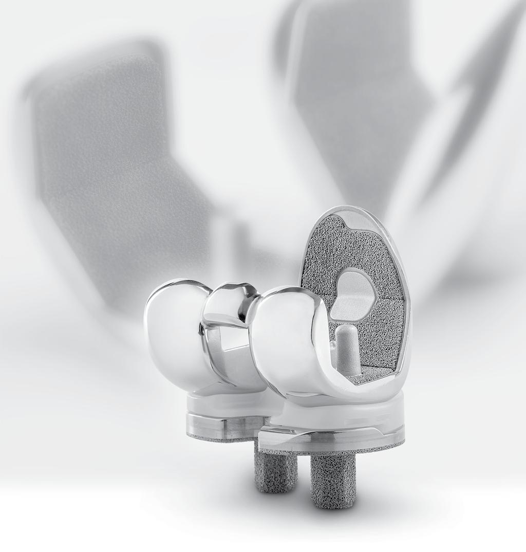
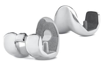
2 INTRO Trabecular Metal Femoral Component Surgical Technique Introduction The Persona Trabecular Metal Femoral Component is designed to unite stable porous femoral component fixation with compatible cruciate-retaining, ultracongruent, and posterior stabilized articular surface implants. This Surgical Technique covers all femoral preparation, finishing, and implantation steps for the Trabecular Metal Femoral Component; please reference the appropriate Persona Knee Surgical Technique for all additional surgical steps including surgical approach, tibia/ patella preparation and implantation, balancing, constraint options, and compatibility. Successful porous femoral component arthroplasty is dependent three key components: 1. Bone Resection Accuracy Precise, flat bone cuts are essential to maximize Trabecular Metal material contact with the resected bone and ensure appropriate press-fit to promote stable, long-term fixation. 2. Patient Bone Quality The Persona Trabecular Metal Femoral component should only be used on patients with good bone quality to ensure in-growth will occur. Stable fixation may be compromised if used on soft, osteoporotic bone quality. 3. Ambulation Period An uncemented total knee replacement requires a period of time to achieve stable bone growth into the Trabecular Metal material for successful, long-term fixation. As such, patient rehabilitation should be tailored for porous knee components. To achieve the three key components vital for successful porous femoral component arthroplasty, some additional TM-specific technique tips are as follows. Saw Blades Use new saw blades and consider changing the saw blade during the surgery if it becomes dull or ineffective. Distal Thickness The Trabecular Metal Femoral Component is approximately 0.5mm thicker distally than the cemented component. Surgeons may elect to account for this thickness during the distal femoral resection or the proximal tibial resection. INTRO.1
3 Trabecular Metal Femoral Component Surgical Technique INTRO Cut Guide Stability Two oblique pins are required for proper stability of the 4-in-1 Cut Guide. A well fixed and stable Cut Guide will help ensure precise bone cuts for proper femoral fit. Follow the order of femoral cuts as described in the technique. Strict adherence to the cut order will help ensure the Cut Guide is stable for all four cuts. Femoral Trial/Implant Insertion Apply upward force on the inserter while impacting the femoral provisional and/or implant. This will assist in achieving the proper orientation of the femoral component on the bone. Due to the press-fit nature of a porous component, more force may be required to insert a porous femoral component than a cemented component. Femoral Trial/Implant Fit A fully seated femoral provisional and/or implant should have no gaps anteriorly, posteriorly, and distally. Gaps in the anterior and posterior chamfer areas are to be expected and can be filled with bone grafting, if desired. The Trabecular Metal material is approximately 0.5mm proud of the implant rails and has a darkened appearance. If no light appears between the distal bone face and the femoral implant, the implant is properly seated. Bone cement is recommended in cases in which the implant fit has been compromised in any way. A compromised fit could be encountered due to femoral re-cuts, component extraction and re-insertion, or unplanned voids in the bone. Trabecular Metal Femoral Components are indicated for use with bone cement if desired. The complete technique contains further details and instructions, wherein TM-specific tips are denoted with the following symbol: INTRO.2
 (i.e. pacemaker). These types of devices may be adversely affected by magnets.")

4 INTRO Trabecular Metal Femoral Component Surgical Technique Magnet Usage Warning: Some instruments in the Persona System contain magnets. All Persona magnetic instruments should be kept at a safe distance from a patient s active implantable medical device(s) (i.e. pacemaker). These types of devices may be adversely affected by magnets. Instruments containing magnets should be kept on an appropriate table or stand when not in use at the surgical site. Symbols Symbols have been established for the following: Left Right Varus/Valgus Medial/Lateral Standard Do not implant Not for implant Lock Unlock Anterior Referencing Do not impact Cemented Stemmed Inset Only M/L Left Right Varus/Valgus Medial/Lateral Std Standard Unlock Do not implant - Not for implant Anterior Referencing Lock Do not impact Screw/Pin Information Cemented Stemmed The chart below contains relevant information on various 3.2mm Pins/Screws that are compatible with the Persona system. If these screws/pins are used during the procedure for instrument fixation, they should be removed prior to closure as they are NOT implantable. Inset Only Screw/Pin Screw/Pin Item # Compatible Driver Shipped Sterile/ Non-sterile Quantity per Package Single use? 25mm x 2.5mm Female Hex Screw * 2.5mm Male Hex Driver mm x 3.2mm Trocar Tipped Drill Pin (2.5mm hex) Hex Headed Screw 33mm long Pin/Screw Inserter Sterile 2 Yes Sterile 4 Yes Sterile 2 Yes *Note: The 2.5mm Female Hex Screws and 2.5mm Male Hex Driver should not be used in cortical bone, as this may increase the incidence of stripping of the driver. MIS Quad-Sparing Total Knee Headed Screw 48mm long Screw Inserter/Extractor Sterile 1 Yes 25mm Shorthead Holding Pin Multi Pin Puller Non-Sterile 1 No INTRO.3
5 Trabecular Metal Femoral Component Surgical Technique TOC Persona Trabecular Metal Femoral Component Surgical Technique Table of Contents Establish Femoral Alignment 1 Resect Distal Femur 3 Size Femur and Establish 5 External Rotation Complete Femoral A/P 7 and Chamfer Resections CR Femoral Finishing 9 PS Femoral Finishing 11 and PS Box Preparation Implant Femoral Component 14 TOC.1
.")
 and insert the IM rod into the femur far enough to ensure the most accurate replication of the anatomic axis, then remove the T-handle (Fig. 3). Insert Fig. 2 TECHNIQUE TIP 1.")
6 1 SECTION Establish Femoral Alignment Establish Femoral Alignment Please refer to the appropriate surgical technique if other distal femoral alignment and distal femoral resection instrumentation is to be used to accomplish the distal femoral resection. After attaining the desired soft tissue exposure, use the 8mm IM Step Drill to make a starter hole (Fig. 1). Suction the canal to remove medullary contents. Fig. 1 Insert the Femoral IM Rod into the Modular T-Handle (Fig. 2) and insert the IM rod into the femur far enough to ensure the most accurate replication of the anatomic axis, then remove the T-handle (Fig. 3). Insert Fig. 2 TECHNIQUE TIP 1.A As the symbol on the T-handle indicates do not impact the T-Handle. Unlock Fig. 3 Instruments 1 Femoral IM Rod Modular T-Handle mm IM Step Drill


7 Establish Femoral Alignment 1 SECTION Retract the spring-loaded button on the top of the Femoral Valgus Alignment Guide and rotate the valgus adjustment dial to the desired valgus angle and release the button to lock the valgus angle from 0 to 9, ensuring that the proper left or right setting is attained (Fig. 4). 2. Rotate 1. Retract 3. Release Retraction Fig. 4 Place the Femoral Valgus Alignment Guide on the IM Rod against the most prominent condyle and confirm the desired valgus setting (Fig. 5). Fig. 5 5 Right Valgus Setting TECHNIQUE TIP 1.B If the epicondyles are visible, the epicondylar axis may be used as a guide in setting the orientation of the Femoral Valgus Alignment Guide. This does not set the rotation of the femoral component, but keeps the distal cut oriented to the final component rotation. If desired, the guide can be pinned to provide rotational stability (Fig. 6). Optional Pinning Holes Fig. 6 Femoral Valgus Alignment Guide mm x 3.2mm Trocar Tipped Drill Pin (2.5mm hex) Pin/Screw Inserter
.")

.")

 were used to maintain rotational alignment of the alignment guide, use the Multi Pin Puller to remove the pin(s). Alternatively, the Pin/Screw Inserter can be used to remove these pin(s).")
8 SECTION 2 Resect Distal Femur Resect Distal Femur Attach the 0 Captured Cutting Head to the Distal Femoral Resection Guide (Fig. 7). The adjustment dial on the resection guide can be set from -2 to +4. The 0 represents a 10mm distal resection (Fig. 8). The -1 setting represents a 9mm resection while the +4 setting represents a 14mm resection. Upon rotation, the dial has palpable stops and clear markings at each 2mm location. One half rotation creates 1mm of adjustment. Insert the resection guide with the cutting head into the alignment guide until the cutting head rests on the anterior femoral cortex. Verify the desired resection setting on the resection guide and/or rotate the adjustment dial to attain the desired setting (Fig. 9). Insert trocar-tipped pins through the two standard pin holes marked 0 on the anterior surface of the cutting head (Fig. 10). Additional 2mm adjustments may be made by removing the cutting head from the pins and replacing the cutting head on the pins in the sets of holes marked -2, +2, and +4. The markings on the cutting head indicate, in millimeters, the amount of bone resection each will yield relative to the initial distal resection setting. Fig. 7 TECHNIQUE TIP 2.A Adjustment Dial If more fixation is desired, insert trocar-tipped pins in the small oblique holes on the cutting head. If pin(s) were used to maintain rotational alignment of the alignment guide, use the Multi Pin Puller to remove the pin(s). Alternatively, the Pin/Screw Inserter can be used to remove these pin(s). Fig. 8 TECHNIQUE TIP 2.B The Trabecular Metal Femoral Component is approximately 0.5mm thicker distally than the Persona Cemented Femoral Component. If desired, additional thickness may be accounted for in the distal femoral resection or the proximal tibia resection. Fig. 9 Instruments 3 Femoral IM Rod Modular T-Handle Femoral Valgus Alignment Guide Distal Femoral Resection Guide Captured/ Uncaptured Cutting Head

9 Resect Distal Femur SECTION 2 Squeeze the button on the resection guide (Fig. 11) to release and remove the alignment guide and resection guide assembly from the cutting head. The modular T-handle is used to remove the IM Rod, prior to the distal femoral resection. Alternatively, the T-handle can be used to remove the IM Rod while the button on the resection guide is squeezed to facilitate rapid removal of the IM rod, the alignment guide and the resection guide at the same time. If necessary, the round end of the Slaphammer Extractor can be used in conjunction with the central hole in the T-Handle to remove the IM rod. Cut the distal femur through the cutting slot in the cutting head, using a 1.27mm (0.050 in.) oscillating saw blade (Fig. 12). If the optional uncaptured technique is used, the distal femur should be cut on the outside surface of the capture. Note: The flatness of the distal femoral resection is critical to ensuring adequate contact between the Persona Trabecular Metal femoral implant and the bone. Evaluate the flatness of the distal femur resection prior to sizing. Fig. 10 Oblique Hole TECHNIQUE TIP 2.C Squeeze to Unlock - It is recommended to use new saw blades for femoral resections. - Areas where the bone transitions from high to low density, such as from cortical to cancellous bone, may cause the saw blade to skive and result in an inconsistent cut. Use caution when resecting in these regions and operate the saw at high speed but advance the saw slowly to ensure a consistent cut. - The flatness of the distal femoral resection is critical to ensuring sufficient contact between the Persona Trabecular Metal femoral implant and the bone. Evaluate the flatness of the distal femur resection with a flat surface, such as the distal resection cutting guide, especially around the intercondylar notch, prior to sizing. Modify the distal femoral surface, if necessary, to ensure subsequent guides and the implant fit properly. Fig. 11 Remove After completing the cut, remove pins and the cutting head. Fig mm x 3.2mm Trocar Tipped Drill Pin (2.5mm hex) Pin/Screw Inserter Multi Pin Puller Persona Slaphammer
. External rotation can be set at 3 or 5 from the posterior condylar axis. Side Designation TECHNIQUE TIP 3.")


 to optimize the M/L position of the drill holes for subsequent Anterior Referencing 4-in-1 Cut Guide placement.")
10 SECTION 3 Size Femur and Establish External Rotation Size Femur and Establish External Rotation Rotate the feet of the Anterior Referencing Sizer so the appropriate Left or Right markings are visible as the Anterior Referencing Sizer is placed on the bone (Fig. 13). External rotation can be set at 3 or 5 from the posterior condylar axis. Side Designation TECHNIQUE TIP 3.A Remove any osteophytes that interfere with instrument positioning. Apply the Anterior Referencing Sizer so that the flat surface of the Anterior Referencing Sizer is flush against the resected surface of the distal femur and the feet of the Anterior Referencing Sizer are flush against the posterior condyles. Center the Anterior Referencing Sizer mediolaterally. Both the vertical and horizontal portions of the Anterior Referencing Sizer provide visual cues relative to the AP and epicondylar axes of the femur to help ensure that desired external rotation is attained. If the 3 external rotation holes are to be used to set external rotation, the etched line on the Anterior Referencing Sizer should be positioned so it is in line with Whiteside s line (Fig. 14) to optimize the M/L position of the drill holes for subsequent Anterior Referencing 4-in-1 Cut Guide placement. If the 5 external rotation holes are to be used, the sizer can be positioned with the etched line on the Anterior Referencing Sizer 4mm laterally from Whiteside s line to better center the drill holes for subsequent Anterior Referencing 4-in-1 Cut Guide placement, due to the M/L offset of the holes. Hold the Anterior Referencing Sizer in place and if necessary, secure the Anterior Referencing Sizer to the femur using 25mm x 3.2mm (2.5mm female hex) screws (Fig. 15) in one or both of the holes on the lower portion of the Anterior Referencing Sizer to help draw the Anterior Referencing Sizer adjacent to the distal femur, particularly in MIS situations. Note: Do not use 48mm screws for fixation of the Anterior Referencing Sizer. 48mm screws are not recommended due to potential bone perforation. Fig. 13 Fig. 14 TECHNIQUE TIP 3.B Do not impact the Anterior Referencing Sizer onto the femur. Fig. 15 Instruments 5 Persona Anterior Referencing Sizer mm Male Hex Driver mm x 3.2mm (2.5mm female hex)
. This will decrease the tension of the patellar tendon to facilitate placement of the Anterior Referencing Sizer Boom.")
.")


.")
11 Size Femur and Establish External Rotation SECTION 3 Slightly extend the knee and retract soft tissues to expose the anterior femoral cortex. Clear any soft tissue from the anterior cortex. Ensure that the leg is in less than 90 of flexion (70-80 ). This will decrease the tension of the patellar tendon to facilitate placement of the Anterior Referencing Sizer Boom. The Anterior Referencing Sizer Boom telescopes proximally/distally to facilitate optimal placement along the anterior cortex. The engraved lines along the top of the boom approximate the anterior flange lengths of the size 1, 7, and 12 femoral components (Fig. 16a). Once the Anterior Referencing Sizer Boom is appropriately positioned, it should be locked in place by tightening the knob at the end of the boom clockwise (Fig. 16b). Fig. 16a Size 1 Size 7 Size 12 TECHNIQUE TIP 3.C - Lock boom after positioning to reduce the toggle of the boom tip. This will also reduce the risk of notching. - Positioning the sizing boom tip on the high part of the femur by lateralizing the location of the sizing boom tip can often lessen the likelihood of notching the femur. - To size accurately, the sizing boom should be telescoped to the size read from the tower. If the boom is telescoped to the exact size, the tip of the boom will approximate the exit point of the saw blade through the anterior cortex. After the Anterior Referencing sizer is appropriately positioned on the femur, read the femoral size from the engraved lines on the sizer tower and select the closest size (Fig. 17). There are six even-sizes labeled on the left side of the tower and six odd-sizes labeled on the right side of the tower, with lines indicating the in-between sizes. The 3 or 5 holes in the midline of the A/P portion of the sizer are used to drill 3.2mm holes for pegs on the Anterior Referencing 4-in-1 Femoral Cut Guide (Fig 18). A 3.2mm pin may be placed in the first drilled hole to maintain an index position prior to drilling the second hole. Remove the screws, then remove the sizer. Fig. 16b Fig. 17 TECHNIQUE TIP 3.D - The Multi Pin Puller cannot be used to extract the screw(s). - This Anterior Referencing Sizer works only with these Anterior Referencing 4-in-1 Femoral Cut Guides and Provisionals, and implants referenced in this technique. Instruments Fig mm x 75mm Trocar Tipped Drill Pin (2.5mm hex) mm Drill
. Impact the face of the guide until the guide is flush with the femur. Fig. 19 TECHNIQUE TIP 4.")
. Fig.")
. Place the next smaller-sized femoral cut guide on the femur in the newly drilled posteriorized drill holes (Fig. 21a & 21b).")

12 SECTION 4 Complete Femoral A/P and Chamfer Resections Complete Femoral A/P and Chamfer Resections By hand, place the 4-in-1 Cut Guide on the femur by aligning the 2 pins on the back of the guide with the previously drilled positioning holes (Fig. 19). Impact the face of the guide until the guide is flush with the femur. Fig. 19 TECHNIQUE TIP 4.A The flatness of the bone and stability of the 4-in-1 Cut Guide on the femur is critical to ensuring sufficient contact between the implant and the bone. Place the Resection Guide through the anterior slot of the cut guide to ensure the desired anterior resection (Fig. 20). Fig. 20 If inadequate bone will be removed from the anterior cortex, drill through the two holes on the face of the cut guide (Fig. 21a). Use the Slaphammer to axially remove the cut guide (Fig. 22a & 22b). Place the next smaller-sized femoral cut guide on the femur in the newly drilled posteriorized drill holes (Fig. 21a & 21b). Verify the anterior and posterior resection levels with the resection guide to assure that the desired resections will be attained. If usage of the smallersized femoral cut guide will result in too much posterior bone removal the original larger-sized femoral cut guide can be used to make a more conservative posterior resection. Fig. 21a TECHNIQUE TIP 4.B If the 2mm shift holes are to be used, assure that the desired holes on the distal femur are used. The resection guide can be used as final verification of the anticipated anterior and posterior resections. Fig. 21b Instruments 7 Persona Anterior Referencing 4-in-1 Cut Guide - Size Resection Guide mm Drill


 thick oscillating saw blade to complete the anterior and posterior resections followed by the posterior chamfer and anterior chamfer resections through the cut slots. (Fig.")

13 Complete Femoral A/P and Chamfer Resections SECTION 4 TECHNIQUE TIP 4.C If there is a risk of anterior notching, the 4-in-1 cut guide can be removed, rotated 180 and be replaced on the distal femur. Holes can then be drilled through the 2mm shift holes on the face of the 4-in-1 guide. The 4-in-1 guide then needs to be removed, rotated 180 and be placed on the distal femur in the anteriorized holes. This will result in a 2mm anterior shift of the 4-in-1 femoral resections. Verify that the desired anterior and posterior resections will be attained. 1. Insert 2. Rotate 3. Extract After final placement of the desired Cut Guide, insert 3.2mm trocar-tipped pins or 3.2mm Headed Screws (see Screw Information section for examples) through the oblique holes in the Cut Guide (Fig. 23). Use a 1.27mm (.050 in.) thick oscillating saw blade to complete the anterior and posterior resections followed by the posterior chamfer and anterior chamfer resections through the cut slots. (Fig. 24) Upon completion of the cuts, use the Multi Pin Puller or Pin/Screw Inserter to remove the oblique pins/screws. Use the Persona Slaphammer to remove the cut guide from the femur (Fig. 22a & 22b). Fig. 22a Fig. 22b TECHNIQUE TIP 4.D It is not recommended that the following Headed Screws are used through the oblique holes of the Cut Guides, as the head of the screw may interfere with the saw blade: , , , Fig. 23 TECHNIQUE TIP 4.E - Areas where the bone transitions from high to low density, such as from cancellous to cortical bone, can lead to the saw blade skiving and inconsistent cuts. Use caution when resection in these regions. Advancing an oscillating saw blade slowly through the bone while using high frequency oscillations will help to ensure a flat, consistent resection. - Check the flatness of all bone resections to ensure sufficient contact will result between the implant and the bone. If necessary, modify the cut surfaces to be completely flat. Fig. 24 Pin/Screw Inserter Multi Pin Puller mm x 3.2mm Trocar Tipped Drill Pin (2.5mm hex)

14 SECTION 5 CR Femoral Finishing CR Femoral Finishing Release Lever TECHNIQUE TIP 5.A Reference the orientation and size etched and/or engraved markings to identify the correct provisional. Assemble the Femoral CR Impactor Pad to the Femoral Inserter/Extractor. Hold the Femoral Inserter/Extractor with the handle in the open position and insert the Femoral CR Impactor Pad, aligning the "CR" on the Femoral CR Impactor Pad with the arrow on the Femoral Inserter/ Extractor (Fig. 25a). The Femoral CR Impactor Pad is keyed, so the Femoral CR Impactor Pad may have to be rotated while placing and aligning the Femoral CR Impactor Pad onto the Femoral Inserter/Extractor. Alignment Arrows Fig. 25a Femoral sizes are provided in two profiles, Standard and Narrow. The Standard femoral provisionals have intermittent cutouts around the periphery, with the inner dimension representing the outer profile of the Narrow femoral implant and the outer dimension representing the outer profile of the Standard femoral implant (Fig. 25b). Care should be taken to use the appropriate Standard or Narrow implant as is related to side (left or right) and size based on the provisional fit and ROM provided during the trialing phase. Note: Narrow phantom lines are for illustration clarity only. Narrow Cutouts Fig. 25b TECHNIQUE TIP 5.B Do not impact the anterior flange of the CR Femoral Provisional. Do not impact the medial or lateral aspects or the release lever of the Femoral Inserter/Extractor. Instruments 9 Inserter/Extractor CR Impactor Pad Persona CR Femoral Provisional Size 7 Right

.")

 with the 2.5mm Male Hex Driver through the hole in the lateral anterior flange of the CR Femoral Provisional (Fig. 28).")

15 CR Femoral Finishing SECTION 5 Remove any posterior osteophytes or overhanging bone on the femur to facilitate maximum knee flexion. Attach the Femoral Inserter/Extractor to the correct CR Femoral Provisional by inserting the tab on the Femoral Inserter/ Extractor arm into the anterior notch in the CR Femoral Provisional and close the handle on the Femoral Inserter/ Extractor to secure the CR Femoral Provisional (Fig. 26). Place the correct CR Femoral Provisional onto the femur in the desired medial/lateral position. Impact the end of the Femoral Inserter/Extractor handle and apply an upward force to fully seat the CR Femoral Provisional onto the femur in the proper orientation. (Fig. 27). To remove the Femoral Inserter/Extractor from the CR Femoral Provisional, pinch the release lever on the proximal portion of the Femoral Inserter/Extractor (Fig. 27). Alternatively, if the CR Femoral Provisional is placed on the femur by hand, the CR femoral Impaction Pad/inserter assembly can be used to impact the provisional onto the femur. If this insertion/impaction method is used, the inserter handle must be in the closed and locked position. For additional fixation of the fully seated provisional, insert the 25mm x 3.2mm screw (2.5mm female hex) with the 2.5mm Male Hex Driver through the hole in the lateral anterior flange of the CR Femoral Provisional (Fig. 28). Note: Do NOT use a 48mm screw in the anterior lateral fixation hole. 48mm screws are not recommended due to potential bone perforation. Once the tibia has been prepared, a trial range of motion can be performed to assure proper positioning of the CR Femoral Provisional prior to femoral peg hole preparation. Once desired medial-lateral placement has been attained, drill the peg holes for the femoral implant through the CR Femoral Provisional with the NexGen 6.4mm Patella/Femoral Drill (Fig. 29). If a screw was used to provide adjunct fixation, remove the screw from the anterior flange in the CR Femoral Provisional. The Slaphammer can be used to remove the CR Femoral Provisional from the bone using the medial hole on the CR Femoral Provisional (Fig. 30). Alternatively, the Femoral Inserter/Extractor can be re-attached to the CR Femoral Provisional to remove it from the bone. If necessary, place the round end of the Slaphammer in the extraction hole of the Femoral Inserter/Extractor to facilitate removal. TECHNIQUE TIP 5.C Do not impact the anterior flange of the CR Femoral Provisional for removal, as this may damage the CR Femoral Provisional. Fig. 26 Pinch to release Fig. 27 Fig. 28 Fig. 29 Fig Rotate 1. Insert 3. Extract Instruments Inserter/Extractor CR Impactor Pad Persona CR Femoral Provisional Size 7 Right mm x 3.2mm (2.5mm female hex) NexGen 6.4mm Patella/Femoral Drill Persona Slaphammer mm Male Hex Driver

.")
16 SECTION 6 PS Femoral Finishing and PS Box Preparation PS Femoral Finishing and PS Box Preparation Release Lever TECHNIQUE TIP 6.A Reference the orientation and size etched and/or engraved markings to identify the correct provisional. Assemble the Femoral PS Impactor Pad to the Femoral Inserter/Extractor. Hold the Femoral Inserter/Extractor, with the handle in the open position and insert the Femoral PS Impactor Pad, aligning the "PS" on the Femoral PS Impactor Pad with the arrow on the Femoral Inserter/ Extractor (Fig. 31a). The Femoral PS Impactor Pad is keyed, so the Femoral PS Impactor Pad may have to be rotated while placing and aligning the Femoral PS Impactor Pad onto the Femoral Inserter/Extractor. Alignment Arrows Fig. 31a Note: Narrow phantom lines are for illustration clarity only. Narrow Cutouts Femoral sizes are provided in two profiles, Standard and Narrow. The Standard femoral provisionals have intermittent cutouts around the periphery, with the inner dimension representing the outer profile of the Narrow femoral implant and the outer dimension representing the outer profile of the Standard femoral implant (Fig. 31b). Care should be taken to use the appropriate Standard or Narrow implant as is related to side (left or right) and size based on the provisional fit and ROM provided during the trialing phase. Fig. 31b Instruments 11 Inserter/Extractor PS Impactor Pad Persona PS Femoral Provisional Size 7 Right


.")

17 PS Femoral Finishing and PS Box Preparation SECTION 6 TECHNIQUE TIP 6.B Do not impact the anterior flange of the PS Femoral Provisional. Do not impact the medial or lateral aspects or the release lever of the Femoral Inserter/Extractor. Remove any posterior osteophytes or overhanging bone on the femur to facilitate maximum knee flexion. Attach the Femoral Inserter/Extractor to the correct PS Femoral Provisional by inserting the tab on the Femoral Inserter/ Extractor arm into the lateral notch in the PS Femoral Provisional and close the handle on the Femoral Inserter/ Extractor to secure the PS Femoral Provisional (Fig. 32). Place the correct PS Femoral Provisional onto the femur in the desired medial/lateral position. Impact the end of the Femoral Inserter/Extractor handle and apply an upward force to fully seat the PS Femoral Provisional onto the femur in the proper orientation. (Fig. 33). To remove the Femoral Inserter/Extractor from the PS Femoral Provisional, pinch the release lever on the proximal portion of the Femoral Inserter/Extractor (Fig. 33). Alternatively, if the PS Femoral Provisional is placed on the femur by hand, the PS Femoral Impaction Pad/inserter assembly can be used to impact the provisional into the femur. If this insertion/impaction method is used, the inserter handle must be in the closed and locked position. For additional fixation of the fully seated PS Femoral Provisional, insert the 25mm x 3.2mm screw (2.5mm female hex) with the 2.5mm Male Hex Driver through the hole in the lateral anterior flange of the PS Femoral Provisional (Fig. 34a). Note: Do NOT use a 48mm screw in the anterior lateral fixation hole of the PS Femoral provisional. 48mm screws are not recommended due to potential bone perforation. By hand, insert and hold the correct-sized PS Box Cut Guide into the anterior holes of the PS Femoral Provisional (Fig. 34b). For additional fixation of the fully seated PS Box Cut Guide, insert the 25mm x 3.2mm screw (2.5mm female hex) with the 2.5mm Male Hex Driver through one of the holes in the PS Box Cut Guide. Separate PS Box Cut Guides exist for the PS Femoral Provisional for sizes 3-5,6-9, and Fig.32 Fig. 33 Pinch to release Fig. 34a Fig. 34b TECHNIQUE TIP 6.C Do not impact the PS Box Cut Guide into the provisional. Instruments Inserter/Extractor PS Impactor Pad Persona PS Femoral Provisional Size 7 Right Persona PS Box Cut Guide Persona PS Box Provisional 6-9 Right
 thick, ½\" wide oscillating or reciprocating saw blade, by resting the saw blade in a parallel manner on the front surface of the PS Box Cut Guide.")


18 SECTION 6 PS Femoral Finishing and PS Box Preparation Make the anterior to posterior PS box cut with a 1.27mm (.050 in.) thick, ½" wide oscillating or reciprocating saw blade, by resting the saw blade in a parallel manner on the front surface of the PS Box Cut Guide. Control the saw to avoid over resection of the medial and lateral condyle in the proximal area of the PS box (Fig. 35a). After completing the anterior-to-posterior box cut, make the vertical wall cuts for the PS notch cuts by resting the saw blade in a parallel manner against the interior sidewalls of the PS Femoral Provisional (Fig. 35b). If a screw was used to provide adjunct fixation, remove the screw and the PS Box Cut Guide. By hand, insert the correct-sized PS Box Provisional into the PS Femoral Provisional to assure that adequate bone has been removed for the implant AND for proper patella trialing. Separate left and right PS Box Provisionals exist for sizes 3-5, 6-9, and PS Femoral Provisionals (Fig. 36). Fig. 35a Fig. 35b TECHNIQUE TIP 6.D Fig. 36 If the appropriately sized PS Box Provisionals does not easily seat into the PS Femoral Provisional, perform clean up cuts to assure adequate bone has been removed. Do NOT impact the PS Box Provisional. Make sure the PS Femoral Provisional is fully seated after inserting the correct PS Box Provisional. Drill the peg holes for the femoral implant through the PS Femoral Provisional with the NexGen 6.4mm Patella/ Femoral Drill (Fig 37). Remove the screw from the anterior flange in the PS Femoral Provisional. Remove the PS Box Provisional. The Slaphammer can be used to remove the PS Femoral Provisional from the bone using the medial hole on the PS Femoral Provisional (Fig 38). Alternatively, the Femoral Inserter/Extractor can be re-attached to the PS Femoral Provisional to remove it from the bone. If necessary, insert the Slaphammer in the extraction hole of the Femoral Inserter/Extractor to facilitate removal. Fig Remove 3. Rotate 4. Extract TECHNIQUE TIP 6.E 2. Insert Do not impact the anterior flange of the PS Femoral Provisional for removal, as this may damage the PS Femoral Provisional. Fig. 38 Instruments 13 25mm x 3.2mm (2.5mm female hex) NexGen 6.4mm Patella/Femoral Drill Persona Slaphammer mm Male Hex Driver


19 Implant Femoral Components SECTION 7 Implant Femoral Components After the implants have been chosen, make a final check to ensure that the size chosen for the femoral, tibial, and articular surface are compatible. Cementless Implantation Option With the knee in of flexion, retract the soft tissue in the desired manner. Attach the Femoral Inserter/Extractor to the femoral component (Fig. 39a & 39b). Insert the femoral component onto the distal femur by translating the component laterally until the lateral peg aligns with the drill hole in the lateral femoral condyle. Take care to avoid scratching the implant component surfaces. After the femoral component is placed on the femur and the inserter/extractor is removed, the impaction head/inserter assembly can be used to impact the component onto the femur. If this insertion/impaction method is used,the inserter handle must be in the closed and locked position. Ensure that soft tissue is not trapped beneath the implant. Alternatively, assemble the Quick Connect Handle to the Femoral Impactor Head (Fig. 40). Use the Femoral Impactor Head assembly to fully seat the femoral component (Fig. 41). Remove retractors, and check the medial and lateral sides to make sure the femoral component is fully impacted distally. Fig. 39a Fig Unlock Collar 4. Rotate Fig. 39b 3. Release 2. Insert TECHNIQUE TIP 7.A - Apply upward force on the Femoral Inserter/Extractor while impacting the femoral implant to ensure component is placed in proper orientation. - Carefully engage the pegs or the intercondylar box of the femoral implant into the pre-drilled peg holes or resected box and impact the femur onto the bone until stable. Periodically check the alignment with the bone cuts to ensure the implant is seating properly. - The Trabecular Metal material extends above the femoral implant rail by approximately 0.5mm and has a dark color, which may appear not fully seated. If no light is visible beneath the distal surface and the bone, the implant is fully seated. Small gaps between the Trabecular Metal surface and the chamfer bone cuts may be visible and are acceptable (Fig. 42). - Do not intra-operatively re-insert a previously extracted Persona Trabecular Metal femoral implant. Fig. 41 Fig. 42 Instruments Femoral Impactor Head Quick Connect Handle Inserter/Extractor PS Impactor Pad CR Impactor Pad Persona Trabecular Metal CR Femoral Component Size 7 Right Persona Trabecular Metal PS Femoral Component Size 7 Right

 to improve cement intrusion. The cement should have a doughy consistency when ready for use.")
20 SECTION 7 Implant Femoral Components Cemented Implantation Option TECHNIQUE TIP 7.B Prior to cementing implants remove provisionals and use pulse lavage to remove unwanted debris from the resected bone surfaces and the joint space. Cement may be used to fix the Persona Trabecular Metal Femoral Component. After the implants have been chosen, make a final check to ensure that all components are compatible. If the resected surfaces of the femur is sclerotic, drill multiple holes with a small drill (2.0mm-3.2mm) to improve cement intrusion. The cement should have a doughy consistency when ready for use. With the knee in of flexion, retract the soft tissue in the desired manner. Place a layer of cement on the underside of the prosthesis and in the holes drilled in the femur. Attach the Femoral Inserter/Extractor to the femoral component (Fig. 43a & 43b). Insert the femoral component onto the distal femur by translating the component laterally until the lateral peg aligns with the drill hole in the lateral femoral condyle. Take care to avoid scratching the implant component surfaces. After the femoral component is placed on the femur and the inserter/ extractor is removed, the impaction head/inserter assembly can be used to implant the component onto the femur. If this inserter/extractor method is used, the inserter handle must be in the closed and locked position. Ensure that soft tissue is not trapped beneath the implant. Alternatively, assemble the Quick Connect Handle to the Femoral Impactor Head (Fig. 44). Use this assembly to fully seat the femoral implant (Fig. 45). Remove retractors, and check the medial and lateral sides to make sure the femoral implant is fully impacted distally. Remove any excess cement in a thorough and consistent manner. Fig. 43a Fig. 43b Fig Unlock Collar 4. Rotate 3. Release 2. Insert Fig. 45 Instruments 15 Femoral Impactor Head Tibial Impactor Head Quick Connect Handle Inserter/Extractor PS Impactor Pad CR Impactor Pad Persona Trabecular Metal CR Femoral Component Size 7 Right Persona Trabecular Metal PS Femoral Component Size 7 Right


21 Implant Femoral Components SECTION 7 Implant the Tibial Component and Articular Surface Refer to the "Implant Components" section of the Persona Knee Surgical Technique for tibial and articular surface insertion instructions. If the tibial component is already in place prior to femoral component insertion, take care to ensure the posterior condyles do not contact the tibial component upon impaction (Fig. 46a & 46b). Fig. 46a Fig. 46b 16
22
23

24 Disclaimer This documentation is intended exclusively for physicians and is not intended for laypersons. Information on the products and procedures contained in this document is of a general nature and does not represent and does not constitute medical advice or recommendations. Because this information does not purport to constitute any diagnostic or therapeutic statement with regard to any individual medical case, each patient must be examined and advised individually, and this document does not replace the need for such examination and/or advice in whole or in part. Please refer to the package inserts for important product information, including, but not limited to, contraindications, warnings, precautions, and adverse effects. Contact your Zimmer representative or visit us at Rev. 1 MC Zimmer, Inc.
Persona. The Personalized Knee. Trabecular Metal Tibia. Surgical Technique
 Persona The Personalized Knee Trabecular Metal Tibia Surgical Technique Table of Contents Resect the Tibia... 4 Size and Finish the Tibia... 4 Trial Fit... 6 Component Implantation... 7 Inserter/Implant
Contact your Zimmer representative or visit us at
 Please refer to the package inserts for complete product information, including contraindications, warnings, precautions, and adverse effects. Contact your Zimmer representative or visit us at www.zimmer.com
Persona The Personalized Knee. Surgical Technique
 Persona The Personalized Knee Surgical Technique Table of Contents Introduction... 2 Constraint Options Preoperative Planning Surgical Approach Patient Preparation Magnet Usage Symbols Screw/Pin Information
14 mm x +30 mm Stem Extension
 14 mm x +30 mm Stem Extension Persona The Personalized Knee Surgical Technique Table of Contents Introduction...2 Preoperative Planning Surgical Approach Patient Preparation Magnet Usage Symbols Screw/Pin
Zimmer NexGen MIS Tibial Component. Cemented Surgical Technique IMAGE TO COME
 Zimmer NexGen MIS Tibial Component Cemented Surgical Technique IMAGE TO COME Zimmer NexGen MIS Tibial Component Cemented Surgical Technique 1 Zimmer NexGen MIS Tibial Component Cemented Surgical Technique
Patient Specific Instruments. Surgical Technique
 Patient Specific Instruments Surgical Technique Patient Specific Instruments Surgical Technique INTRO Introduction General Considerations Zimmer Patient Specific Instruments (PSI) are not designed for
Distal Cut First Femoral Preparation
 Surgical Technique Distal Cut First Femoral Preparation Primary Total Knee Arthroplasty LEGION Total Knee System Femoral preparation Contents Introduction...3 DCF femoral highlights...4 Preoperative planning...6
Zimmer NexGen Trabecular Metal Tibial Tray
 Zimmer NexGen Trabecular Metal Tibial Tray Surgical Technique Zimmer NexGen Trabecular Metal Tibial Tray Surgical Technique Give Bone A Solid Hold Zimmer NexGen Trabecular Metal Tibial Tray Surgical Technique
Constrained Posterior Stabilized (CPS) Surgical Technique
 Surgical Technique") Constrained Posterior Stabilized (CPS) Surgical Technique Constrained Posterior Stabilized (CPS) Surgical Technique INTRO Introduction The Constrained Posterior Stabilized (CPS) articular surfaces can
Constrained Posterior Stabilized (CPS) Surgical Technique Constrained Posterior Stabilized (CPS) Surgical Technique INTRO Introduction The Constrained Posterior Stabilized (CPS) articular surfaces can
TOTAL KNEE ARTHROPLASTY SYSTEM
 SURGICAL TECHNIQUE TOTAL KNEE ARTHROPLASTY SYSTEM 90-SRK-700000 B.0 0 Contents 1. Implant Sizing 2. Surgical Technique a. Incision and Exposure b. Distal Femoral Resection c. Tibial Resection d. Femoral
MIS Cemented Tibial Component
 MIS Cemented Tibial Component NexGen Complete Knee Solution Surgical Technique Table of Contents Surgical Exposure... 2 Finish the Tibia... 2 Position Based on Anatomic Landmarks... 3 Lateral Posterior
Zimmer Trabecular Metal Ankle Interpositional Spacer and Trabecular Metal Ankle Fusion Spacer
 Zimmer Trabecular Metal Ankle Interpositional Spacer and Trabecular Metal Ankle Fusion Spacer Surgical Technique 2 Zimmer Trabecular Metal Ankle Interpositional Spacer and Trabecular Metal Ankle Fusion
Zimmer Patient Specific Instruments. Surgical Technique for Gender Solutions Natural-Knee Flex System
 Zimmer Patient Specific Instruments Surgical Technique for Gender Solutions Natural-Knee Flex System TOC Zimmer Patient Specific Instruments Surgical Technique for Gender Solutions Natural-Knee Flex Table
Zimmer Patient Specific Instruments. Surgical Techniques for NexGen Complete Knee Solution
 Zimmer Patient Specific Instruments Surgical Techniques for NexGen Complete Knee Solution INTRO Zimmer Patient Specific Instruments Surgical Techniques for NexGen Complete Knee Solution Table of Contents
TRK REVISION KNEE Surgical Technique
 1 TRK REVISION KNEE Surgical Technique 1. 2. 3. 4. 5. 6. 7. 8. 9. 10. INTERCONDYLAR RESECTION...... page FEMORAL STEM...... page NON CEMENTED FEMORAL STEM...... page TRIAL FEMORAL COMPONENTS...... page
Zimmer FuZion Instruments. Surgical Technique (Beta Version)
") Zimmer FuZion Surgical Technique (Beta Version) INTRO Surgical Technique Introduction Surgical goals during total knee arthroplasty (TKA) include establishment of normal leg alignment, secure implant fixation,
Zimmer FuZion Surgical Technique (Beta Version) INTRO Surgical Technique Introduction Surgical goals during total knee arthroplasty (TKA) include establishment of normal leg alignment, secure implant fixation,
Triathlon Knee System
 Triathlon Knee System Express Instruments Surgical Protocol Posterior Stabilized & Cruciate Retaining TriathlonKneeSystem Express Instruments Surgical Protocol Acknowledgments..........................................................2
Zimmer NexGen Tibial Stem Extension & Augmentation. Surgical Technique IMAGE TO COME. Stem Extensions and Augments
 Zimmer NexGen Tibial Stem Extension & Augmentation Surgical Technique IMAGE TO COME Stem Extensions and Augments Zimmer NexGen Tibial Stem Extension & Augmentation Surgical Technique 1 Zimmer NexGen Tibial
NexGen Trabecular Metal Tibial Tray. Surgical Technique
 NexGen Trabecular Metal Tibial Tray Surgical Technique Table of Contents Surgical Technique...2 Resect the Tibia...2 Finish the Tibia...2 Position Based Anatomic Landmarks...3 Position Based on Trial
ANTERIOR REFERENCE NEXGEN COMPLETE KNEE SOLUTION. Multi-Reference 4-in-1 Femoral Instrumentation Anterior Reference Surgical Technique
 ANTERIOR REFERENCE NEXGEN COMPLETE KNEE SOLUTION Multi-Reference 4-in-1 Femoral Instrumentation Anterior Reference Surgical Technique For NexGen Cruciate Retaining & Legacy Posterior Stabilized Knees INTRODUCTION
Constrained Posterior Stabilized (CPS)
") Constrained Posterior Stabilized (CPS) Persona The Personalized Knee Surgical Technique Table of Contents Introduction... 2 Constraint Options Initial Knee Assessment... 3 Femoral Box Cut CPS Tibial Bearing
Constrained Posterior Stabilized (CPS) Persona The Personalized Knee Surgical Technique Table of Contents Introduction... 2 Constraint Options Initial Knee Assessment... 3 Femoral Box Cut CPS Tibial Bearing
A novel cementless option. Zimmer NexGen Trabecular Metal Primary Patella Surgical Technique
 A novel cementless option Zimmer NexGen Trabecular Metal Primary Patella Surgical Technique Zimmer Trabecular Metal Primary Patella 1 Zimmer NexGen Trabecular Metal Primary Patella Surgical Technique
POSTERIOR REFERENCE NEXGEN COMPLETE KNEE SOLUTION. Multi-Reference 4-in-1 Femoral Instrumentation Posterior Reference Surgical Technique
 POSTERIOR REFERENCE NEXGEN COMPLETE KNEE SOLUTION Multi-Reference 4-in-1 Femoral Instrumentation Posterior Reference Surgical Technique For NexGen Cruciate Retaining & Legacy Posterior Stabilized Knees
Surgical Technique. VISIONAIRE Disposable Instruments for the LEGION Total Knee System
 Surgical Technique VISIONAIRE Disposable Instruments for the LEGION Total Knee System VISIONAIRE and LEGION Disposable instrument technique* Note: All disposable instruments are interchangeable with the
ZIMMER NEXGEN CRUCIATE RETAINING (CR) AND LEGACY KNEE POSTERIOR STABILIZED (LPS) TRABECULAR METAL MONOBLOCK TIBIAS. Surgical Technique Addendum
 AND LEGACY KNEE POSTERIOR STABILIZED (LPS) TRABECULAR METAL MONOBLOCK TIBIAS. Surgical Technique Addendum") ZIMMER NEXGEN CRUCIATE RETAINING (CR) AND LEGACY KNEE POSTERIOR STABILIZED (LPS) TRABECULAR METAL MONOBLOCK TIBIAS Surgical Technique Addendum SURGICAL TECHNIQUE FOR NEXGEN CRUCIATE RETAINING (CR) AND
ZIMMER NEXGEN CRUCIATE RETAINING (CR) AND LEGACY KNEE POSTERIOR STABILIZED (LPS) TRABECULAR METAL MONOBLOCK TIBIAS Surgical Technique Addendum SURGICAL TECHNIQUE FOR NEXGEN CRUCIATE RETAINING (CR) AND
Intramedullary Tibial Preparation
 Surgical Technique Intramedullary Tibial Preparation Primary Total Knee Arthroplasty LEGION Total Knee System Intramedullary tibial preparation Contents Introduction...2 IM tibial highlights...3 Preoperative
Trabecular Metal Primary Patella
 Trabecular Metal Primary Patella NexGen Complete Knee Solution Surgical Technique Table of Contents Introduction... 2 Prepare the Patella... 2 Patella Reamer Technique... 3 Insetting Technique... 5 Universal
LAMINA SPREADER SURGICAL TECHNIQUE
 LAMINA SPREADER SURGICAL TECHNIQUE Balanced and appropriate external rotation of the femoral component is important for tibio-femoral stability in flexion and patello-femoral tracking/function. Depending
NATURAL MOTION TECHNOLOGY SURGICAL TECHNIQUE. EMPOWR 3D Knee. EMPOWR PS Knee
 NATURAL MOTION TECHNOLOGY EMPOWR 3D Knee EMPOWR PS Knee SURGICAL TECHNIQUE Contents System Features.... 3 Indications and Contraindications.... 4 Surgical Snap Shot.... Preoperative Planning.... Surgical
NexGen Cruciate Retaining (CR) and Revision Instrumentation. Surgical Technique
 and Revision Instrumentation. Surgical Technique") NexGen Cruciate Retaining (CR) and Revision Instrumentation Surgical Technique Table of Contents Introduction... 4 Revision Arthroplasty... 4 Multi-Reference 4-in-1 Instrumentation System MICRO-MILL Instrumentation
NexGen Cruciate Retaining (CR) and Revision Instrumentation Surgical Technique Table of Contents Introduction... 4 Revision Arthroplasty... 4 Multi-Reference 4-in-1 Instrumentation System MICRO-MILL Instrumentation
Surgical Technique. VISIONAIRE FastPak Instruments for the LEGION Total Knee System
 Surgical Technique VISIONAIRE FastPak Instruments for the LEGION Total Knee System VISIONAIRE FastPak for LEGION Instrument Technique* Nota Bene The technique description herein is made available to the
TRUMATCH PERSONALIZED SOLUTIONS with the SIGMA High Performance Instruments
 TRUMATCH PERSONALIZED SOLUTIONS with the SIGMA High Performance Instruments Resection Guide System SURGICAL TECHNIQUE RESECTION GUIDE SURGICAL TECHNIQUE The following steps are an addendum to the SIGMA
PRIMARY POROUS PATELLA WITH TRABECULAR METAL. Surgical Technique
 PRIMARY POROUS PATELLA WITH TRABECULAR METAL Surgical Technique 1 SURGICAL TECHNIQUE FOR NEXGEN PRIMARY POROUS PATELLA * WITH TRABECULAR METAL CONTENTS PREPARE THE PATELLA............... 2 Patella Reamer
PIN GUIDE SYSTEM SURGICAL TECHNIQUE. with the SIGMA High Performance Instruments System. This publication is not intended for distribution in the USA.
 PIN GUIDE SYSTEM with the SIGMA High Performance Instruments System This publication is not intended for distribution in the USA. SURGICAL TECHNIQUE Pin Guide Surgical Technique The following steps are
Extramedullary Tibial Preparation
 Surgical Technique Extramedullary Tibial Preparation Primary Total Knee Arthroplasty LEGION Total Knee System Extramedullary tibial preparation Contents Introduction...2 EM tibial highlights...3 Preoperative
TRUMATCH PERSONALIZED SOLUTIONS with the SIGMA High Performance Instruments
 TRUMATCH PERSONALIZED SOLUTIONS with the SIGMA High Performance Instruments Pin Guide System SURGICAL TECHNIQUE PIN GUIDE SURGICAL TECHNIQUE The following steps are an addendum to the SIGMA High Performance
NEXGEN COMPLETE KNEE SOLUTION S A. Tibial Stem Extension & Augmentation Surgical. ATechnique
 NEXGEN COMPLETE KNEE SOLUTION ATechnique Tibial Stem Extension & Augmentation Surgical INTRODUCTION The NexGen Complete Knee Solution Intramedullary Tibial Instruments have been designed to provide an
Zimmer NexGen RH Knee Primary/Revision. Surgical Technique
 Zimmer NexGen Primary/Revision Surgical Technique Zimmer NexGen Primary/Revision Surgical Technique INTRO Introduction The NexGen Rotating Hinge Knee () is designed for revision, difficult primary, and
RESECTION GUIDE SYSTEM. TRUMATCH Personalized Solutions Surgical Technique with ATTUNE Knee INTUITION Instruments
 RESECTION GUIDE SYSTEM TRUMATCH Personalized Solutions Surgical Technique with ATTUNE Knee INTUITION Instruments RESECTION GUIDE SURGICAL TECHNIQUE The following steps are an addendum to the ATTUNE Knee
ANATOMIC SURGICAL TECHNIQUE. 5 in 1. Conventional instrumentation 07/11/2013
 ANATOMIC SURGICAL TECHNIQUE 5 in 1 Conventional instrumentation PRO.GB.933/1.0 Octobre 2013 2 Tibial step 3 Intramedullary technique - Based on the preoperative plan, drill the medullary canal with the
U2 PSA. Revision Knee. Surgical Protocol
 U2 PSA TM Revision Knee Surgical Protocol Table of Contents 1 Component Removal... 1 2 Tibial Preparation... 1 2.1 Tibial Canal Preparation... 1 2.2 Proximal Tibial Resection... 2 2.3 Non Offset Tibial
Zimmer PSI Knee System For Use with Persona The Personalized Knee System Surgical Technique
 Zimmer PSI Knee System For Use with Persona The Personalized Knee System Surgical Technique TOC Zimmer PSI Knee Surgical Technique Zimmer PSI Knee Surgical Technique Table of Contents Intra-Operative Guide
NexGen Intramedullary Instrumentation. Surgical Technique
 NexGen Intramedullary Instrumentation Surgical Technique Table of Contents Introduction... 2 Preoperative Planning... 2 Surgical Technique... 3 Step One: Size the Femur/Establish External Rotation...
NexGen Complete Knee Solution. Cruciate Retaining (CR) and Revision Instrumentation Surgical Technique for Cruciate Retaining Augmentable (CRA) Knees
 and Revision Instrumentation Surgical Technique for Cruciate Retaining Augmentable (CRA) Knees") NexGen Complete Knee Solution Cruciate Retaining (CR) and Revision Instrumentation Surgical Technique for Cruciate Retaining Augmentable (CRA) Knees INTRODUCTION This surgical technique document combines
NexGen Complete Knee Solution Cruciate Retaining (CR) and Revision Instrumentation Surgical Technique for Cruciate Retaining Augmentable (CRA) Knees INTRODUCTION This surgical technique document combines
Pin Guide System. Surgical Technique
 Pin Guide System Surgical Technique Pin Guide Surgical Technique The following steps are an addendum to the SIGMA High Performance (HP) Instruments, Fixed Reference Surgical Technique (Cat. No. 0612-87-510
The information contained in this document is intended for healthcare professionals only.
 The information contained in this document is intended for healthcare professionals only. Triathlon Knee System Posterior Stabilized & Cruciate Retaining Table of Contents Acknowledgments.......................................................1
Triathlon with Single-Use Instrumentation Optimize Your TKA Experience. Posterior Referencing Surgical Protocol
 Triathlon with Single-Use Instrumentation Optimize Your TKA Experience Posterior Referencing Surgical Protocol Introduction............................................................2 Assembly Instructions...................................................6
Zimmer NexGen MIS Tibial Component. Cemented Surgical Technique. IMAGE TO COME Designed for minimally invasive procedures
 Zimmer NexGen MIS Tibial Component Cemented Surgical Technique IMAGE TO COME Designed for minimally invasive procedures Zimmer NexGen MIS Tibial Component Cemented Surgical Technique 1 Zimmer NexGen MIS
MRH Knee System Modular Peg Baseplate Surgical Protocol
 MRH Knee System Modular Peg Baseplate Surgical Protocol Using Monogram IM Revision Instruments 4 N 4 N Modular Rotating Hinge Knee System Using Monogram IM Revision Instruments Mr C R Howie FRCS Consultant
Triathlon Tritanium. Surgical Protocol. with Triathlon Cementless Beaded PA Femoral Component
 Triathlon Tritanium Surgical Protocol with Triathlon Cementless Beaded PA Femoral Component Triathlon Tritanium Surgical Protocol with Triathlon Cementless Beaded PA Femoral Component Description...............................
PPS P I N P O S I T I O N I N G S Y S T E M GMK EFFICIENCY VERSION. Hip Knee Spine Navigation
 PPS P I N P O S I T I O N I N G S Y S T E M D ESIGNED FOR YOU BY YOU GMK EFFICIENCY VERSION Surgical Surgical Technique Hip Knee Spine Navigation MyKnee Surgical Technique Hip Knee Spine Navigation I N
Zimmer Gender Solutions Patello-Femoral Joint (PFJ) System. Surgical Technique IMAGE TO COME. Advancing the science of partial knee replacement.
 System. Surgical Technique IMAGE TO COME. Advancing the science of partial knee replacement.") Zimmer Gender Solutions Patello-Femoral Joint (PFJ) System Surgical Technique IMAGE TO COME Advancing the science of partial knee replacement. Zimmer Gender Solutions Patello-Femoral Joint (PFJ) System
Zimmer Gender Solutions Patello-Femoral Joint (PFJ) System Surgical Technique IMAGE TO COME Advancing the science of partial knee replacement. Zimmer Gender Solutions Patello-Femoral Joint (PFJ) System
Single Axis Revision Knee System
 Orthopaedics Scorpio TS Single Axis Revision Knee System Scorpio TS Trial Cutting Guide Surgical Protocol Orthopaedics Scorpio TS Single Axis Revision Knee System Scorpio TS Trial Cutting Guide Surgical
INTUITION INSTRUMENTS SURGICAL TECHNIQUE
 INTUITION INSTRUMENTS SURGICAL TECHNIQUE Introduction This surgical technique provides guidelines for the implantation of the ATTUNE Knee System Family of Knee Implants with the INTUITION Instrumentation.
FLK167 02/08. Biomet UK Ltd Waterton Industrial Estate Bridgend, South Wales CF31 3XA, United Kingdom. Tel Fax:
 FLK167 02/08 Biomet UK Ltd Waterton Industrial Estate Bridgend, South Wales CF31 3XA, United Kingdom Tel. 01656 655221 Fax: 01656 645454 Premier Instrumentation CR or PS Surgical Technique Vanguard Premier
Revolution. Unicompartmental Knee System
 Revolution Unicompartmental Knee System While Total Knee Arthroplasty (TKA) is one of the most predictable procedures in orthopedic surgery, many patients undergoing TKA are in fact excellent candidates
NexGen LPS Fixed Bearing Knee. Surgical Technique
 NexGen LPS Fixed Bearing Knee Surgical Technique Table of Contents Introduction...2 Preoperative Planning...2 Surgical Technique...3 Step One: Align the Tibia...3 MICRO-MILL Hand Piece Assembly and Usage
INTUITION INSTRUMENTS SURGICAL TECHNIQUE
 INTUITION INSTRUMENTS SURGICAL TECHNIQUE Introduction This surgical technique provides guidelines for the implantation of the ATTUNE Knee System Family of Knee Implants with the INTUITION Instrumentation.
1. Pre-Operative Planning Skin Incision and Arthrotomy
 Stage of Operation 1. Pre-Operative Planning --------------------------1 2. Skin Incision and Arthrotomy ------------------1 3. Femoral valgus angle confirmation ------------2 4. Distal Femur Cutting -----------------------------3
Trabecular Metal Tibial Cone Surgical Technique
 Trabecular Metal Tibial Cone Surgical Technique Provides structural support in areas of bone loss Trabecular Metal Cone 1 Zimmer Trabecular Metal Tibial Cone Surgical Technique Table of Contents Overview
EXACTECH KNEE. Operative Technique ADDENDUM. Metaphyseal Cones. Surgeon focused. Patient driven. TM
 EXACTECH KNEE Operative Technique ADDENDUM Metaphyseal Cones Surgeon focused. Patient driven. TM TABLE OF CONTENTS INTRODUCTION...1 DESCRIPTION...1 DETAILED OPERATIVE TECHNIQUE Initial Preparation and
BIOTECH FUTURE KNEE Minimal Invasive (and classic) Surgical Technique
 Surgical Technique") BIOTECH FUTURE KNEE Minimal Invasive (and classic) Surgical Technique Page No. Product description 2. Pre-operational planning 3. 1st step Femoral resection 4. P/S Femoral component 7. 2nd step Proximal
BIOTECH FUTURE KNEE Minimal Invasive (and classic) Surgical Technique Page No. Product description 2. Pre-operational planning 3. 1st step Femoral resection 4. P/S Femoral component 7. 2nd step Proximal
Triathlon TS Knee System. Surgical Protocol
 Triathlon TS Knee System Surgical Protocol Triathlon TS Knee System Surgical Protocol Table of Contents Acknowledgments..........................................................2 Exposure...................................................................4
Total Knee Original System Primary Surgical Technique
 Surgical Procedure Total Knee Original System Primary Surgical Technique Where as a total hip replacement is primarily a bony operation, a total knee replacement is primarily a soft tissue operation. Excellent
Operative Technique. Constrained Condylar. The Right Track It s not just a road we re on, it s a trail we re blazing.
 Operative Technique Constrained Condylar The Right Track It s not just a road we re on, it s a trail we re blazing. TABLE OF CONTENTS Introduction...1 Design rationale...1 operative technique Overview...2
NEXGEN COMPLETE KNEE SOLUTION. Revision Instrumentation Surgical Technique For Legacy Knee Constrained Condylar Knee
 NEXGEN COMPLETE KNEE SOLUTION Revision Instrumentation Surgical Technique For Legacy Knee Constrained Condylar Knee INTRODUCTION Revision total knee arthroplasty can be a very challenging task for any
The ACL-PCL Substituting Knee. BioFoam Tibial Bases. Surgical Technique For Cementless Tibial Fixation
 The CL-PCL Substituting Knee BioFoam Surgical Technique For Cementless Tibial Fixation Surgical techniques and instrument recommendations were provided by: Michael nderson, MD Milwaukee, WI G. Lynn Rasmussen,
Profix. Total Knee System. As described by
 Profix Total Knee System P R I M A R Y P R O C E D U R E As described by Leo A. Whiteside, M.D. Associate Research Professor Washington University School of Medicine Director, Biomechanical Research Laboratory
ClassiQ. Scorpio. Anterior Referencing Surgical Protocol. Anterior Referencing. For use with Scorpio ClassiQ Instrument System
 Scorpio ClassiQ Anterior Referencing Surgical Protocol For use with Scorpio ClassiQ Instrument System For use with Scorpio ClassiQ Single Radius Total Knee System AR Anterior Referencing This document
Medial Rotation Knee. Forever Active. Landmark Operative Technique Supplement: No.1 All-Polyethylene Tibia (Cemented)
") Medial Rotation Knee Landmark Operative Technique Supplement: No.1 All-Polyethylene Tibia (Cemented) Physiological Stability and Mobility for the Active Knee Without Compromise Forever Active Contents
Medial Rotation Knee Landmark Operative Technique Supplement: No.1 All-Polyethylene Tibia (Cemented) Physiological Stability and Mobility for the Active Knee Without Compromise Forever Active Contents
Zimmer NexGen Rotating Hinge Knee Primary/ Revision
 Zimmer NexGen Rotating Hinge Knee Primary/ Revision Surgical Technique Designed for use in revision and difficult primary surgeries 1 INTRODUCTION The NexGen Rotating Hinge Knee Components are designed
OPERATIVE TECHNIQUE SKS Total Knee Replacement
 OPERATIVE TECHNIQUE SKS Total Knee Replacement Femoral preparation A40577 1 2 5 1: Alignment rod A30049 + A30124 2: Centromedullary rod A40224 4: T-handle A40232 6: Femoral measuring device A40411 + A40414
Triathlon Knee System. Universal Baseplate Surgical Protocol
 Triathlon Knee System Universal Baseplate Surgical Protocol Table of Contents Acknowledgments..........................................................2 Introduction...............................................................2
Zimmer Unicompartmental High Flex Knee. Spacer Block Surgical Technique
 Zimmer Unicompartmental High Flex Knee Spacer Block Surgical Technique INTRO Zimmer Unicompartmental High Flex Knee Spacer Block Surgical Technique Introduction Unicompartmental knee arthroplasty (UKA)
Zimmer MOST Options System
 Zimmer MOST Options System Surgical Technique Modular Options for Severe Bone Loss and Trauma Zimmer MOST Options System Surgical Technique 1 MOST Options System Surgical Technique Developed in conjunction
Knee. Surgical Protocol
 U2 TM PS CR Knee Surgical Protocol Table of Contents Pre-Operative Planning... Surgical Incision... 1 2 A. Femoral Preparation A.1. Pilot Hole... A.2. Femoral Valgus Angle Confirmation... A.3. Distal
Triathlon Knee System Universal Baseplate Surgical Protocol
 Triathlon Knee System Universal Baseplate Surgical Protocol Triathlon Knee System Universal Baseplate Surgical Protocol Table of Contents Acknowledgments... 2 Introduction... 2 Assembly Instructions...
Zimmer Unicompartmental High Flex Knee. Intramedullary, Spacer Block Option and Extramedullary Minimally Invasive Surgical Techniques
 Zimmer Unicompartmental High Flex Knee Intramedullary, Spacer Block Option and Extramedullary Minimally Invasive Surgical Techniques ZIMMER UNICOMPARTMENTAL HIGH FLEX KNEE INTRAMEDULLARY, SPACER BLOCK
Table of Contents. Step One: Locate Medullary Canal 4 Step Two: Prepare Femur 4. Step Three: Size Femur 5. Step Four: Prepare Tibia 5
 Zimmer Natural-Knee Unicompartmental MIS Intramedullary Surgical Technique Zimmer MIS Surgical Technique for Unicompartmental Knee Arthroplasty Developed in conjunction with Aaron A. Hofmann, MD Professor
KneeAlign System Surgical Technique Guide
 KneeAlign System Surgical Technique Guide Table of Contents Step 1 System Assembly... 1 Step 2 System Assembly... 2 Step 3 System Assembly... 2 Step 4 System Assembly... 2 Step 5 Sensor Pairing... 2 Step
Zimmer MIS Intramedullary Instrumentation
 Zimmer MIS Intramedullary Instrumentation Surgical Technique For NexGen Cruciate Retaining & NexGen Legacy Posterior Stabilized Knees Zimmer MIS Intramedullary Instrumentation Surgical Technique Surgical
unicompartmental knee SURGICAL TECHNIQUE limacorporate.com
 unicompartmental knee SURGICAL TECHNIQUE limacorporate.com Index INTRAMEDULLARY (IM) SURGICAL PROCEDURE Introduction Page >> 04 Rationale Page >> 05 Preoperative Planning Page >> 07 Patient Preparation
Proven Gen-Flex Revision Knee System. Surgical Protocol
 Proven Gen-Flex Revision Knee System Surgical Protocol Proven Gen-Flex Revision Knee System Surgeon Design Team The Proven Gen-Flex Revision Knee System Instrumentation and Surgical Protocol were developed
AGC Total Knee System. Concise Surgical Technique Featuring EquiFlex Instrumentation
 AGC Total Knee System Concise Surgical Technique Featuring EquiFlex Instrumentation AGC TOTAL KNEE SYSTEM Concise Surgical Technique Instrumentation Disclaimer This brochure provides a description of the
Longevity Offset and Oblique Liners. Surgical Technique
 Longevity Offset and Oblique Liners Surgical Technique Longevity Offset & Oblique Liners Surgical Technique 1 Introduction Complete Acetabular System Joint instability is an important issue in both primary
Resurfacing Distal Femur. Orthopaedic Salvage System
 Resurfacing Distal Femur Orthopaedic Salvage System Primary Arthroplasty OSS 3cm Resurfacing Distal Femur Distal Femoral Resection Drill and ream the distal femur in the following sequence: (Figure 1)
Triathlon Knee System. Anterior Referencing Surgical Protocol
 Triathlon Knee System Anterior Referencing Surgical Protocol Triathlon Knee System Anterior Referencing Surgical Protocol Table of Contents Acknowledgments..........................................................2
STABILITY FOR LIFE. Surgical Technique
 STABILITY FOR LIFE Surgical Technique Joint Spine Sports Med GMK Sphere Surgical Technique 2 INDEX 1. INTRODUCTION 4 1.1 Indications 4 1.2 Contraindications 4 1.3 Preoperative planning 5 1.4 Surgical approach
ZMR Over-the-Junction Instruments for Revision Hip Arthroplasty. Surgical Technique IMAGE TO COME
 ZMR Over-the-Junction Instruments for Revision Hip Arthroplasty Surgical Technique IMAGE TO COME ZMR Over-the-Junction Instruments for Revision Hip Arthroplasty Introduction The ZMR Over-the-Junction (OTJ)
Approach Patients with Confidence
 Surgical Technique Approach Patients with Confidence The ACTIS Total Hip System is the first DePuy Synthes stem specifically designed to be utilized with tissue sparing approaches, such as the anterior
G K SPHERE. Surgical Technique STABILITY FOR LIFE. Hip Knee Spine Navigation
 G K SPHERE M E D I A L L Y S T A B I L I Z E D K N E E STABILITY FOR LIFE Surgical Technique Hip Knee Spine Navigation GMK SPHERE Surgical Technique Hip Knee Spine Navigation INTRODUCTION This brochure
Patella Planing System
 REFERENCE GUIDE AND SURGICAL TECHNIQUE Patella Planing System SPECIALIST INSTRUMENTS AN ONLAY PATELLA PREPARATION SYSTEM TECHNIQUE FOR PRIMARY PATELLAR RESURFACING The Specialist 2 Patellar Planer System
Microplasty Elite Total Knee Instrumentation
 Microplasty Elite Total Knee Instrumentation Vanguard Complete Knee System Surgical Technique Table of Contents Indications and Contraindications... 3 Introduction... 4 Patient Selection Preoperative
Vanguard ID Total Knee. Surgical Technique
 Vanguard ID Total Knee Surgical Technique Table of Contents Overview... 2 Preoperative Planning... 4 Incision... 4 Patella Preparation... 5 Patella Resection Femoral Preparation... 8 Distal Femoral Resection
Mako. Total Knee with Triathlon. Surgical protocol
 Mako Total Knee with Triathlon Surgical protocol Mako Total Knee with Triathlon Surgical protocol Contents Introduction.... 4 Femoral.... 9 Femoral trial assessment... 14 Final tibial and trialing...
Knee. Surgical Protocol
 U2 TM PS CR Knee Surgical Protocol Table of Contents Pre-Operative Planning... Surgical Incision... 1 2 A. Femoral Preparation A.1. Pilot Hole... A.2. Femoral Valgus Angle Confirmation... A.3. Distal
Surgical Technique Final Trial Reduction and Component Implantation of
 Surgical Technique Final Trial Reduction and Component Implantation of TC *smith&nephew TC-PLUS PRIMARY Fixed Bearing TC-PLUS PRIMARY Fixed Bearing Final Trial Reduction and Component Implantation of
DePuy Orthopaedics, Inc. 700 Orthopaedic Drive Warsaw, IN USA Tel: +1 (800)
") DePuy Orthopaedics, Inc. 700 Orthopaedic Drive Warsaw, IN 46581-0988 USA Tel: +1 (800) 366 8143 0086 Printed in USA. DePuy Synthes Companies 2013 All rights reserved. 0612-09-512 Rev 1 5M 0513 Surgical
DePuy Orthopaedics, Inc. 700 Orthopaedic Drive Warsaw, IN 46581-0988 USA Tel: +1 (800) 366 8143 0086 Printed in USA. DePuy Synthes Companies 2013 All rights reserved. 0612-09-512 Rev 1 5M 0513 Surgical