INTUITION INSTRUMENTS SURGICAL TECHNIQUE
|
|
|
- Phebe Ford
- 6 years ago
- Views:
Transcription


1 INTUITION INSTRUMENTS SURGICAL TECHNIQUE
2 Introduction This surgical technique provides guidelines for the implantation of the ATTUNE Knee System Family of Knee Implants with the INTUITION Instrumentation. ATTUNE Knee System Implants are available in four configurations: Posterior Stabilized Fixed Bearing (PS FB), Posterior Stabilized Rotating Platform (PS RP), Cruciate Retaining Fixed Bearing (CR FB) and Cruciate Retaining Rotating Platform (CR RP) The Cruciate Retaining (CR) configurations can also be used for Cruciate Sacrificing (CS) applications.
3 Contents Key Surgical Steps Summary 2 Incision and Exposure 4 Pinning 5 Pinning Technique 6 Distal Femoral Resection 7 Distal Femoral Resection - Instrument Assembly 8 Distal Femoral Resection 10 Tibial Alignment and Resection - Instrument Assembly 14 Tibial Alignment and Resection 15 Extension Gap Assessment and Balancing 20 Femoral Rotation 22 Measured Femoral Sizing and Rotation 23 Balanced Femoral Sizing and Rotation 29 Femoral Preparation 37 Posterior Condyle Preparation 42 Femoral Resection - PS Femoral Notch Cuts 44 Trial Reduction 46 Soft Tissue Considerations for Cruciate Retaining Application 48 Trial Components 49 Tibial Preparation 53 Patella Resection and Preparation Instrument Assembly 55 Patella Resection 57 Patella Preparation 59 Lug Hole Preparation 62 Tibial Base Implantation 63 Femoral Component Implantation 65 Tibial Insert Implantation 68 Final Patella Preparation 70 Patella Component Implantation 71 Closure 72 Appendix 1: Optional Patella Drilling Technique 73 Appendix 2: Optional Minimally Invasive Instrument Technique 74 Appendix 3: Optional Lamina Spreader Technique 78 Flexion/Extension Gap Chart 81 Tibial Component Sizing Chart 82 Compatibility Data 83 Symbols on Surgical Instruments 84 ATTUNE Knee System Surgical Technique DePuy Synthes Companies 1


4 Key Surgical Steps Summary Incision and Exposure Femoral Alignment and Distal Resection Measured Femoral Sizing and Rotation Femoral Preparation Balanced Femoral Sizing and Rotation Femoral Lug Hole Preparation Patella Resection and Final Patella Preparation 2 DePuy Synthes Companies ATTUNE Knee System Surgical Technique


5 Tibial Alignment and Proximal Resection Extension Gap Assessment and Balancing Trial Reduction Tibial Preparation Note: All resections are done using a 1.19 mm Saw Blade to maximize accuracy through the Slotted Cutting Guides. Final Component Implantation ATTUNE Knee System Surgical Technique DePuy Synthes Companies 3


6 Incision and Exposure The INTUITION Instruments are designed for both standard open and minimally invasive approaches to the knee. Incision and exposure should be performed using the surgeon s preferred technique. i INFORMATION Excise any hypertrophic synovium and a portion of the infrapatellar fat pad to allow access to the medial, lateral, and intercondylar spaces. Before proceeding, consider removing prominent osteophytes, particularly medial and lateral osteophytes, as they can affect soft tissue balancing. Accurate patella alignment is important for proper placement and tracking. It is recommended not to drill the patella lug holes prior to the trialing step so that correct rotation and position of the patella trial may be assessed. Many of the instruments on the following pages are made of polymer materials. As with any composite or polymer-based instrument, it is important to allow adequate drying time after cleaning. 4 DePuy Synthes Companies ATTUNE Knee System Surgical Technique


7 Pinning The ATTUNE Knee System has 3.15 mm diameter pins to increase the stability and functionality of the instruments. The INTUITION Instruments are designed to be used with the Single-Use Pin Pack ( ) that contains Universal Pins and Threaded Headed Pins. Threaded Non-Headed Pins are also shown below. Universal Pin The Universal Pin can be drilled in or hammered in, and drilled out or pulled out using the Pin Jack. Threaded Headed Pin The Threaded Headed Pin is designed to be inserted and removed with a Power Drill. These pins are best used to secure blocks against a flat surface such as cut bone. Threaded Non-Headed Pin The Threaded Non-Headed Pin is also available and is designed to be inserted and removed with a Power Drill. i INFORMATION Pin Jack Steinmann Pins are compatible with all pin holes throughout the INTUITION Instruments. It is recommended to use Threaded Headed Pins through the divergent holes in the A/P Chamfer Block to provide sufficient stability against the distal femoral cut. Power Driver ATTUNE Knee System Surgical Technique DePuy Synthes Companies 5


8 Pinning Technique Correct Pinning Incorrect Pinning Do not overtighten. Overtightening may change the angle or cause the pin to strip. Headed Pins are best used to secure blocks against a flat surface such as cut bone. Non-Headed Pins are recommended for use with cutting blocks against a curved surface such as with the Distal Cut Block. 6 DePuy Synthes Companies ATTUNE Knee System Surgical Technique
.")
9 Distal Femoral Resection If the Balanced Sizer is intended to be used, then the position of the IM hole is important as it determines the pivot point for femoral rotation. It should be selected to be 3-5 mm medial to the apex of the intercondylar notch and 7-10 mm anterior to the origin of the Posterior Cruciate Ligament (PCL). Drawing a centering mark or Whiteside s Line and the pre-operative X-ray may be useful to assist precise location of the IM hole. In the proper position, the Step Drill should pass easily into the femoral canal. Use the step feature of the Step Drill to increase the diameter of the hole. This will allow depressurization of the canal when the IM Rod is inserted. ATTUNE Knee System Surgical Technique DePuy Synthes Companies 7


10 Distal Femoral Resection Instrument Assembly Distal Femoral Jig Assembly Order of Assembly: 1. Rotate the Resection Knob of the Outrigger counterclockwise until the padlock symbol is aligned with the arrow. 2. Insert the Outrigger Slide into the Outrigger. 3. Rotate the Resection Knob clockwise to set the desired resection level. 4. Engage the Distal Femoral Cutting Block with the Outrigger Slide and the Cutting Block Clip. Resection Knob Outrigger Pull Back Outrigger Slide Cutting Block Clip Distal Femoral Cutting Block 8 DePuy Synthes Companies ATTUNE Knee System Surgical Technique


11 Distal Femoral Resection Instrument Assembly A 9 mm resection will match the thickness of the implant. The arrow on the Outrigger, near the Resection Knob, indicates the resection level when using the Cutting Slot. Each click moves the Distal Femoral Cutting Block 1 mm proximal or distal. Distal Resection Depth 4 mm difference between a Slotted and Non-Slotted resection Resection Knob adjusts distal resection depth ATTUNE Knee System Surgical Technique DePuy Synthes Companies 9
 on")
 Dial toward the Femoral Handle, rotating it")


12 Distal Femoral Resection Set the desired Valgus angle (left or right - 0 degrees to 9 degrees) on the Distal Femoral Jig by pulling the Varus/Valgus (V/V) Dial toward the Femoral Handle, rotating it clockwise or counterclockwise to the appropriate setting. V/V Indicator Cap Distal Plate Fixation Pin Holes V/V Dial i INFORMATION Be sure that the Varus/Valgus Dial is FULLY disengaged by sliding it back from the Distal Plate before rotating it. 10 DePuy Synthes Companies ATTUNE Knee System Surgical Technique


13 Distal Femoral Resection Insert the IM Rod into the femoral canal to the level of the isthmus. Disengage the Distal Femoral Jig from the Handle by pushing on the V/V Indicator Cap and slide the Jig toward the femur until the distal plate contacts the distal femur. The Jig may be pinned temporarily using pin holes in the distal resection plate. Position the Distal Femoral Cutting Block on the anterior femur by rotating it until it is seated on the anterior condyles. ATTUNE Knee System Surgical Technique DePuy Synthes Companies 11


14 Distal Femoral Resection Secure the Cutting Block to the femur with two Universal or Non-Headed Pins through the holes marked with a center line. If necessary for additional stability, insert a Universal or Non-Headed Pin through one of the divergent pin holes on the Cutting Block. Divergent Pin Hole Removal of the Distal Femoral Jig Pull Distally Disengage the Distal Femoral Cutting Block from the Outrigger Slide by pressing the Red Cutting Block Clip. Pull the entire instrument distally. To further adjust the distal resection depth once the Distal Femoral Jig is removed, use the distal or proximal pin holes, that move the block 2 mm in either direction. Cutting Block Clip 12 DePuy Synthes Companies ATTUNE Knee System Surgical Technique

15 Distal Femoral Resection Resect the distal femur. Remove the Distal Femoral Cutting Block. Depending on surgeon preference, the Pins may be removed or left in place to allow for a recut if required. ATTUNE Knee System Surgical Technique DePuy Synthes Companies 13


16 Tibial Alignment and Resection Instrument Assembly Right Tibial Cutting Block Proximal Central Marking Complete Assembly Tibial Jig Assembly Extramedullary Tibial Proximal Uprod Posterior Slope Adjustment With the Height Adjustment Knob fully unscrewed on the Tibial Proximal Uprod, attach the Tibial Distal Uprod to the Proximal Uprod. Then attach the Tibial Ankle Clamp to the Distal Uprod. Assemble the appropriate Cutting Block to the Tibial Proximal Uprod. Height Adjustment Knob Cutting Block Options Extramedullary Tibial Ankle Clamp Indicator Line Left Tibial Cutting Block A/P Adjustment Mechanism Right Tibial Cutting Block A/P Ratchet V/V Adjustment Mechanism Extramedullary Tibial Distal Uprod Symmetrical Cutting Block 14 DePuy Synthes Companies ATTUNE Knee System Surgical Technique


17 Tibial Alignment and Resection Pinch Lever Set the tibial posterior slope as depicted on the Proximal Uprod of the Tibial Jig, according to the recommendations depending on the appropriate implant configuration. Place the knee in 90 degrees of flexion. Place the Ankle Clamp around the malleoli. Set Varus/Valgus rotation by aligning the proximal central marking on the Tibial Cutting Block with the medial one third of the tibial tubercle. The axis of the Proximal Uprod should be positioned with reference to the tibial axis. Note that the figures on the Jig will only deliver that angle if the rest of the Jig is set up correctly as pictured here. If the slope adjustment is changed after the Cutting Block is resting against bone, the surgeon should re-align the Uprod to be parallel to the tibial axis by moving the A/P adjustment mechanism. i INFORMATION Tibia Slope Recommendations: For a Posterior Stabilized (PS) configuration it is recommended to set the tibial posterior slope at 3 degrees. For a Cruciate Retaining or Cruciate Sacrificing (CR/CS) configuration, a range of 5-7 degrees of tibial posterior slope is recommended, attempting to match the patient s slope. In PCL-retaining TKA not adding adequate slope may limit the postoperative flexion. ATTUNE Knee System Surgical Technique DePuy Synthes Companies 15


18 Tibial Alignment and Resection When checking and setting the sagittal alignment, be careful to prevent anterior slope. This could happen if the A/P Boss on the Distal Uprod is translated too far towards the ankle, exposing the Through-Slot. Posterior slope adjustment is the equivalent to using Cutting Blocks with slope built into them. Through-Slot A/P Ratchet A/P Boss Side Slot V/V Adjustment Use the Varus/Valgus Adjustment Mechanism to align the Tibial Proximal Uprod parallel to the long axis of the tibia. For many patients, this involves translating the V/V Adjustment Mechanism until the second line from the lateral side of the ankle clamp lines up with the indicator line. Indicator Line i INFORMATION In ankles with a large soft tissue envelope in which the soft tissue prevents achieving 0 degrees of alignment at the neutral position, the Distal Uprod can be moved posterior to reveal the Through-Slot to achieve a 0 degree slope. 16 DePuy Synthes Companies ATTUNE Knee System Surgical Technique


. Each number corresponds to a resection amount in millimeters.")
19 Tibial Alignment and Resection Stylus Attachment Attach the Adjustable Tibial Stylus to the Cutting Block through the slot feature. Resection Knob Pointer Foot 4 mm difference between a Slotted and Non-Slotted resection Resection through the Slot If planning to resect through the slot, position the foot of the Stylus marked slot into the Slot Feature of the Cutting Block. Resection on top of the Cutting Slot If planning to resect on top of the Cutting Block, place the foot marked non-slot into the Slot Feature. i INFORMATION The minimum composite thickness of the tibial implant (4 mm base +5 mm insert) is 9 mm. Rotate the Resection Knob to set the resection level on the Stylus (0 to 10). Each number corresponds to a resection amount in millimeters. Rest the pointer of the Adjustable Tibial Stylus on the lowest point of the tibial plateau. Then lock the Height Adjustment Knob on the Proximal Uprod. ATTUNE Knee System Surgical Technique DePuy Synthes Companies 17


20 Tibial Alignment and Resection After the height has been set, pin the block through the holes marked by a center line using two Universal Pins. If necessary, remove the Stylus for better access, ensuring that the Height Adjustment Knob is locked. The resection level can be adjusted by using the distal or proximal pin holes, which move the block 2 mm in either direction. If desired, the Cutting Block can be more securely fixed with an additional Universal or Non-Headed Pin placed through the distal angled hole. Distal Angled Hole Temporary Fixation Pin Slot 18 DePuy Synthes Companies ATTUNE Knee System Surgical Technique


21 Tibial Alignment and Resection Optional: To assess long leg alignment, place the Alignment Handle into the Slot Feature of the Cutting Block, and insert the Alignment Rod. Alignment can be checked by ensuring that the Alignment Rod remains parallel with the tibial axis. In addition, a second Alignment Rod may be inserted through the Alignment Handle in the M/L plane to help ensure that the tibia is not cut in Varus or Valgus. Resect the tibia. i INFORMATION Place retractors to protect the PCL and collateral ligaments during tibial resection if a CR implant is chosen. ATTUNE Knee System Surgical Technique DePuy Synthes Companies 19


22 Extension Gap Assessment and Balancing Spacer Base Shim Spacer Block Posterior Stabilized For the PS technique, connect the ATTUNE Knee System Spacer Base and desired Shim to the Spacer Block to assess both the extension and flexion gaps. When the ATTUNE Knee Spacer Base is attached, both ends of the Spacer Block are equal thickness and can each be connected to a different Shim to allow successive evaluation of multiple thicknesses. As an example, if the surgeon is unsure as to whether the gap will correspond to a 5 mm or 6 mm insert, the 5 mm Shim can be connected to one end and the 6 mm Shim to the other. Cruciate Retaining For the CR technique, evaluate the CR extension gap as described in the previous paragraph. To assess the CR flexion gap connect the CR Flexion Base and desired Shim to one end of the Spacer Block. The CR Flexion Base compensates for the 1 mm difference in thickness of the posterior condyles of the CR implant. PS CR Distal Condyle Thickness 9 9 Posterior Condyle Thickness 9 8 i INFORMATION The Spacer Block is designed to accommodate both CR and PS techniques. In the PS implant the distal and posterior condyles are the same thickness, resulting in no compensation required for extension and flexion balancing. In the CR implant the posterior condyle is 1 mm thinner than the distal condyles. The Spacer Block connects to Shims on both ends to evaluate multiple thicknesses. The labels on the Shims indicate the thickness of the insert they represent when assembled to the Spacer Block, and can be read off the top of the Shim when it is attached to the Spacer Block. Although any size Shim will assemble to the Spacer Block, the size 5/6 Shim is recommended as it most closely matches the shape of the Spacer Block. 20 DePuy Synthes Companies ATTUNE Knee System Surgical Technique


23 Extension Gap Assessment and Balancing To check the extension gap, fully extend the leg and place the appropriate end of the Spacer Block between the two resected surfaces. The Block should fit snugly in the extension space. The extension gap should be rectangular with the leg in full extension. If the extension gap is not balanced, adjust the angle of either the tibial or the femoral cut, or perform appropriate soft-tissue releases to achieve balance. If desired, perform a gentle Varus/Valgus stress test with the Spacer Block in place. Typically 1 mm to 3 mm of opening both medially and laterally is desirable. If desired, the two piece Alignment Rod can be inserted into the Spacer Block to assess alignment. The Spacer Block can also be used to assess the flexion gap after resecting the posterior femoral condyles. ATTUNE Knee System Surgical Technique DePuy Synthes Companies 21

24 Femoral Rotation There are multiple ways of setting the femoral rotation, such as the Measured Sizer or Balanced Sizer Balanced and appropriate external rotation of the femoral component is important for tibiofemoral stability in flexion and patellofemoral tracking/function. Depending on the surgeon s preference, rotation may be set with reference to either key anatomical landmarks via the measured resection approach, or by balancing the soft tissues in flexion with the goal of generating a rectangular flexion gap. A secondary check to key anatomical landmarks should also be made to avoid malrotation of the femoral component. Balanced Sizer Measured Sizer i INFORMATION Proper soft tissue balance is important for successful Knee Replacement. It is especially important in a Rotating Platform (RP) knee construct to reduce the risk of spin out of the tibial insert. 22 DePuy Synthes Companies ATTUNE Knee System Surgical Technique


25 Measured Femoral Sizing and Rotation Measured Sizing and Rotation Guide Size Locking Knob Stylus Anterior Down Pin Hole Anterior Down Pin Hole Femoral Size Markings Femoral Rotation Lever Fixation Pin Holes Posterior Up Pin Hole Feet Posterior Up Pin Hole Anatomic Reference Mark i INFORMATION Choosing the anterior down pin holes will provide a fixed anterior reference with a constant anterior cut, regardless of the size of the A/P Chamfer Block. All variability in bone cuts from size to size will occur on the posterior cut. Rotation Markings Conversely, choosing the posterior up pin holes will provide a fixed posterior reference with a fixed posterior cut. All variability in bone cuts from size to size will occur on the anterior cut. The Measured Sizer instrument is named to indicate its use for a Measured Resection surgical philosophy and is not a measurement device. ATTUNE Knee System Surgical Technique DePuy Synthes Companies 23
 and/or the epicondylar axis on the resected distal femur.")


26 Measured Femoral Sizing and Rotation Placement of Sizing Guide Mark the A/P Axis (Whiteside's line) and/or the epicondylar axis on the resected distal femur. Whiteside's Line Epicondylar Axis Threaded Headed Pin through the Fixation Hole Place the Measured Sizing and Rotation Guide against the resected surface of the distal femur with the posterior feet of the Guide contacting the posterior condyles. If desired, secure the Guide with a Threaded Headed Pin through the fixation hole. 24 DePuy Synthes Companies ATTUNE Knee System Surgical Technique


27 Measured Femoral Sizing and Rotation Setting Rotation Squeeze the Lever and simultaneously rotate Adjust the degree of external rotation to be parallel to the epicondylar axis and perpendicular to Whiteside's line by squeezing the Femoral Rotation Lever and rotating the anterior section while holding the feet of the device against the posterior condyles. Whiteside's Line Epicondylar Axis Right Side Left Side The rotation markings indicate the degree of external femoral rotation with reference to the posterior condyles ATTUNE Knee System Surgical Technique DePuy Synthes Companies 25


28 Measured Femoral Sizing and Rotation Size Locking Knob! Slide the anterior section down. Adjust the superior-inferior position of the Stylus to indicate the proper femoral component size. The position of the Stylus will have an effect on the femoral component sizing. Pick the M/L position of the Stylus to match the highest point of the anterior femur at the appropriate size indication on the Stylus scale. The position of the Stylus will then be located near the exit point of the Saw Blade. Read the scale from the distal side of the Size Locking Knob. The line through the center of the Anterior Down Pin Holes indicates the size of the femur. Lock the size position by twisting the Size Locking Knob. Anterior Down Pin Holes indicating Size 5! CAUTION Be very careful not to apply a large force when contacting the anterior femur with the Stylus, avoiding excessive deflection of the Stylus which may bias the sizing. 26 DePuy Synthes Companies ATTUNE Knee System Surgical Technique


.")

29 Measured Femoral Sizing and Rotation Pin Insertion Insert Universal or Non-Headed Pins through the top pin holes for anterior down referencing OR Insert Universal or Non-Headed Pins through the bottom pin holes for posterior up referencing (For further information see page 23). ATTUNE Knee System Surgical Technique DePuy Synthes Companies 27


30 Measured Femoral Sizing and Rotation Removal of Sizer Threaded Headed Pin Remove the Threaded Headed Pin, if utilized. 2. Release the Knob by rotating counterclockwise. 3. The Stylus is loosened, then pushed forward on the anterior face of the femur so that it is no longer contacting the bone surface (as the anterior surface slopes downward). The Sizer is pulled off the femur and the two components removed together. 4. Remove the Sizing/Rotation Guide, leaving the Universal or Non-Headed Pins in the distal femur. 28 DePuy Synthes Companies ATTUNE Knee System Surgical Technique


31 Balanced Femoral Sizing and Rotation Balanced Sizing/Rotation Guide Assembly To accommodate differences in the flexion gap assessment between the CR and PS Femoral Implants, two different feet are available. Attach the appropriate CR or PS Balanced Sizer Foot to the Balanced Sizing/Rotation Guide. Tensioning Knob Stylus Locking Knob Sizing Scale Pin Holes Insert Thickness Scale Foot IM Rod Hole ATTUNE Knee System Surgical Technique DePuy Synthes Companies 29


32 Balanced Femoral Sizing and Rotation Balanced Sizing and Rotation Guide The Balanced Sizer performs several key functions: 1. Sizes the femur 2. Sets rotation of the femoral component based on ligament tension 3. Enables assessment of the flexion gap in comparison to the previously determined extension gap Before using the Balanced Sizer, clear osteophytes to remove any impingement of soft tissues especially in the posterior capsule. Measure the extension gap using the Spacer Block. After making the primary cuts and measuring the extension gap, record the insert thickness that corresponds to the extension gap for future reference. Attach the IM Rod Handle to the Balanced Sizer IM Rod and insert the Rod into the intramedullary canal. i INFORMATION The Balanced Sizer technique is anterior referencing only. The Tapered Plug may not fit flush against the bone, but should be tight. Use the handle as a Slap Hammer to secure the Tapered Plug and stabilize the IM Rod. The IM Rod should not be inserted past the isthmus to ensure that the angle of the rod is not affected. Ensure that the IM canal has been prepared up to the wider diameter of the Step Drill. 30 DePuy Synthes Companies ATTUNE Knee System Surgical Technique


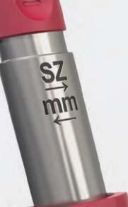
33 Balanced Femoral Sizing and Rotation Sizing the Femur Slide the main body and foot of the Balanced Sizer onto the IM Rod with the knee flexed at 90 degrees, ensuring that the feet clear the posterior condyles. 2. Turn the Tensioning Knob in a counterclockwise direction (in the direction of the SZ arrow) until the Foot contacts the posterior femoral condyles. Once the Foot contacts the posterior femoral condyles the sizer should not be able to rotate about the IM Rod. 1. Slide the Sizing Guide and Stylus over the main body of the Balanced Sizer until the Stylus touches the anterior femur. Locking Knob should be loose at this point of the process i INFORMATION Once the Foot of the Balanced Sizer has contacted the posterior femoral condyles, be careful not to excessively rotate the Tensioning Knob in the direction of the SZ arrow as this could result in disassembling the device. ATTUNE Knee System Surgical Technique DePuy Synthes Companies 31


34 Balanced Femoral Sizing and Rotation Confirm that the Guide is firmly placed against the distal femoral cut with the knee flexed at 90 degrees. Adjust the superior-inferior position of the Stylus to indicate the proper femoral component size. The position of the Stylus will have an effect on the femoral component sizing. Pick the M/L position of the Stylus to match the highest point of the anterior femur at the appropriate size indication on the Stylus scale. The position of the Stylus will then be located near the exit point of the Saw Blade. Foot of Sizer contact posterior condyles of femur Sizer fits against distal femoral cut surface Stylus tip touches the highest point on the anterior femur Size 5! Then determine the femoral component size indicated by lining up the black SZ line on the main body of the balancer with the white numbers on the sizing scale.! CAUTION Be very careful not to apply a large force when contacting the anterior femur with the Stylus. At this point in the procedure do NOT lock the assembly by turning the Locking Knob. The Locking Knob should only be turned to lock the assembly after completion of balancing and in preparation of pin placement. 32 DePuy Synthes Companies ATTUNE Knee System Surgical Technique


35 Balanced Femoral Sizing and Rotation Interpreter for Balanced Sizer The optional Interpreter performs two functions: 1. It allows the surgeon to visualize the position and rotation of the posterior cut prior to placing reference pins 2. The window feature aides in reading the insert thickness scale relative to the femoral component size selected The Interpreter is assembled to the sizer such that the size measured is displayed through the window. ATTUNE Knee System Surgical Technique DePuy Synthes Companies 33
 direction until the flexion gap matches the previously measured")


 across from the previously determined femoral size indication (denoted by the")
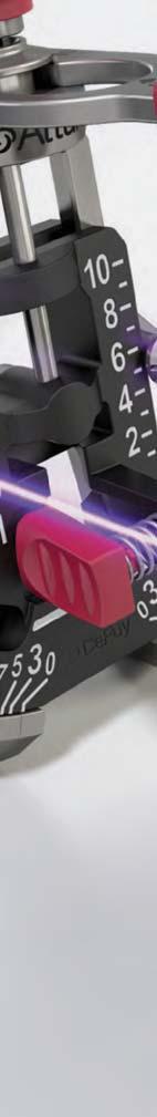
36 Balanced Femoral Sizing and Rotation Setting Femoral Rotation Turn the Tensioning Knob in a clockwise (in the direction of the mm arrow) direction until the flexion gap matches the previously measured extension gap. 8 mm tibial insert thickness for a size 5 femoral component i INFORMATION Ensure that the Sizer has good contact with the distal femur. The leg should be at 90 degrees and the Sizer Foot should rest on the proximal tibia. As tension is applied the femur rotates, therefore it is important to review and adjust the Stylus to the recommended position which is the highest point on the anterior femur relative to the appropriate size. To determine the tibial insert thickness read the insert thickness scale (denoted by the black markings on the main body) across from the previously determined femoral size indication (denoted by the high contrast white markings on the sizing scale). e.g. This image indicates an 8 mm tibial insert for a size 5 femoral component. 34 DePuy Synthes Companies ATTUNE Knee System Surgical Technique


37 Balanced Femoral Sizing and Rotation Check for lift-off! To assess the ligament tension, hold the tibia firmly and use the Tensioning Knob to apply a Varus/Valgus stress while observing lift off between the Foot and the tibial cut. Posterior resection level! CAUTION Over-rotation of the lateral condyle in the anterior direction could result in excessive external rotation of the femoral component and could be an indication of over-tightening. The posterior feet of the Interpreter may be used to visualize the position and rotation of the posterior resection. If further tension is required, turn the Tensioning Knob in a clockwise direction until the next thickness of insert is reached and conduct a further assessment of the ligaments using a Varus/Valgus stress test. If the predicted insert thickness in flexion is not matching the previously measured extension thickness, then the surgeon may need to consider moving the femoral component position by 1.5 mm in an anterior or posterior direction, or upsizing or downsizing the femoral component, using the A/P Chamfer Block. Refer to the Flexion/Extension Gap Chart section for further gap balancing information. ATTUNE Knee System Surgical Technique DePuy Synthes Companies 35


38 Balanced Femoral Sizing and Rotation Verify the appropriate position of the Stylus, then, lock the assembly in place by rotating the Locking Knob clockwise. Insert Universal Pins into the Pin Holes on each side of the Sizing Scale. Insert Pins Remove the Balanced Sizer. First unlock the Locking Knob and release the tension by turning the Tensioning Knob in a counterclockwise direction. Attach the Rod Handle and remove the IM Rod with the Tapered Plug, engage the Tapered Plug with the guide to remove it from the bone. 36 DePuy Synthes Companies ATTUNE Knee System Surgical Technique

39 Femoral Preparation A/P Chamfer Block +1.5 mm Hole Sulcus window as a visual reference for sulcus placement Center Line Hole -1.5 mm Hole Anterior Down Referencing Pin Holes Posterior Up Referencing Pin Holes Modular Posterior Saw Capture to aid balancing flexion space with Spacer Blocks Narrow Size Reference Cutout The cutout indicates the width of the narrow size of implants i INFORMATION The ATTUNE Knee System femoral components increase in size by a consistent 3 mm in the A/P direction. The INTUITION A/P Chamfer Blocks allow the surgeon to adjust the A/P position of the femoral component by 1.5 mm in either direction. This creates the intra-operative flexibility to position the femoral component based on the surgeon s assessment of the flexion gap and the desired posterior condylar offset. See page 81 for more information on gap balancing. If there is no cutout, a narrow component is not available for that size. Narrow components are available for sizes 3, 4, 5 and 6. ATTUNE Knee System Surgical Technique DePuy Synthes Companies 37


40 Femoral Preparation Alignment Slots A/P and Chamfer Cuts Select the A/P Chamfer Block that matches the femur size. Place the Block over the two anterior or posterior Universal or Non-Headed Pins through the pin holes marked with a center line. The flexion space can be checked by using a Spacer Block placed below the A/P Chamfer Block with the Modular Posterior Saw Capture removed. i INFORMATION When using the anterior offset pin holes, changing the size of the femoral component will alter the posterior femoral condyle resection. To evaluate femoral size adjustments without altering the posterior femoral cut, place the A/P Chamfer Block onto the anterior Universal Pins and insert two additional pins through the posterior up holes on the Block. Then remove the anterior reference pins. This enables the femoral implant size to be adjusted without altering the flexion gap. Alternatively, the Block can be moved 1.5 mm up or down (one hole location) to adjust the flexion gap, if necessary. 38 DePuy Synthes Companies ATTUNE Knee System Surgical Technique


41 Femoral Preparation i INFORMATION Good pinning technique is critical to achieving accurate bone cuts during the anterior and posterior resections. The recommended technique is to avoid stripping the Threaded Headed Pins in the divergent pin holes and to retain the straight pins during anterior and posterior resections for added stability. Angel Wing Use an Angel Wing to confirm the location of the cut and the degree of rotation. The Block can also be used at this stage to assess the M/L width of the implant size for both the standard or narrow sizes. Insert Threaded Headed Pins into the divergent pin holes on the medial and lateral aspects of the A/P Chamfer Block. ATTUNE Knee System Surgical Technique DePuy Synthes Companies 39


42 Femoral Preparation i INFORMATION INTUITION A/P Chamfer Blocks were designed to ensure the femoral trial and implant seats fully on the distal femur by preparing the chamfer cuts with additional clearance. Therefore, a small gap may be observed between the femoral trial/implant and the chamfer cuts, particularly the anterior chamfer. This gap is intentional by design to ensure that fixation is achieved with the distal, anterior, and posterior surfaces. In this way, the position of the femoral component can be best controlled with regards to flexion and extension gaps. Recommended: Re-attach the appropriate size Modular Posterior Saw Capture to the A/P Chamfer Block to provide for capture guidance on all cuts. 40 DePuy Synthes Companies ATTUNE Knee System Surgical Technique


43 Femoral Preparation Place Retractors to protect the medial and lateral collateral ligaments and the popliteal tendon. Then resect the anterior and posterior femur, as well as the anterior chamfer if posterior referencing or posterior chamfer if anterior referencing.!! CAUTION Remove the Universal or Non-Headed Pins and cut the remaining anterior or posterior chamfer. Remove the Threaded Headed Pins and the A/P Chamfer Block. i INFORMATION It is recommended to revisit the anterior and posterior femoral cuts after the initial resection to avoid the effect of Saw Blade skiving. The posterior Saw Captures are open medially and laterally to accommodate complete saw cuts. To reduce the risk of inadvertent Saw Blade kickout, point the Blade slightly toward the midline before starting the Saw. ATTUNE Knee System Surgical Technique DePuy Synthes Companies 41


44 Posterior Condyle Preparation Removal of Excess Bone Reference Window Dotted lines indicate the outer edges of the final component Cutouts indicate narrow size For optimal stability, place Base Pins as shown To avoid impingement in flexion, remove any excess bone between the posterior tibial implant and the posterior femoral condyles in flexion. To aid in osteophyte and excess bone removal, select the Femoral Finishing Guide that corresponds to the femoral trial component size. Push the instrument onto the resected distal femur and position mediolaterally, using the lateral anterior profile of the instrument as a guide. The inner surface of the windows represents the anterior medial aspect of the implant and the outside profile of the anterior face represents the anterior lateral aspect of the implant. i INFORMATION Fix the instrument flush to the distal cut using 4.7 mm diameter Base Pins. The cutouts on the sides of the Femoral Finishing Guide show where the outer edge of the narrow component is located. If there is no cutout, a narrow component is not available for that size. Narrow components are available for sizes 3, 4, 5 and 6. Base Pin 42 DePuy Synthes Companies ATTUNE Knee System Surgical Technique
 Curved Osteotome With the Femoral Finishing Guide in place, verify that any excess bone or residual")


45 Posterior Condyle Preparation Removal of Excess Bone (Cont.) Curved Osteotome With the Femoral Finishing Guide in place, verify that any excess bone or residual osteophytes in the posterior recesses have been removed. If not, use a Curved Osteotome or Gouge to remove any remaining bone that can be seen beyond the end of the Femoral Finishing Guide feet. Always work carefully under direct vision to avoid damage to the neurovascular structures in the popliteal fossa. CR Sulcus Femoral Preparation When implanting an ATTUNE Knee System CR component, use the Femoral Finishing Guide to perform the sulcus cut. Using the Sulcus Cut Ramp as a guide, remove bone from the sulcus with the Rasp, a 0.5 in. Saw or Osteotome. Then remove the Femoral Finishing Guide. Sulcus Cut Ramp ATTUNE Knee System Surgical Technique DePuy Synthes Companies 43

46 Femoral Resection PS Femoral Notch Cuts Reference Window Dotted lines indicate the outer edges of the final component The tongue of the Notch Guide is extended to provide a long cutting surface for an 18 degree cut When implanting an ATTUNE Knee System PS component, use the Notch Guide to perform the notch cut. The profile of the Notch Guide provides anterior and distal references to the width of the implant. In addition, windows in the Notch Guide provide additional reference. For optimal stability, place Threaded Headed Pins as shown The inner surface of the windows represents the anterior medial aspect of the implant and the outside profile of the Notch Guide represents the anterior lateral aspect of the implant. The references are designed to confirm optimal component size and position. The tongue of the Notch Guide is extended to provide a long cutting surface for an 18 degree cut. i INFORMATION Position the Notch Guide on the resected anterior and distal surfaces of the femur as far laterally as possible while assuring that the lateral border of the implant does not overhang the lateral femoral cortex. Pin the Guide in place using the Threaded Headed Pins. The cutouts on the sides of the Notch Guide show where the outer edge of the narrow component is located. If there is no cutout, a narrow component is not available for that size. Narrow components are available for sizes 3, 4, 5 and DePuy Synthes Companies ATTUNE Knee System Surgical Technique


47 Femoral Resection PS Femoral Notch Cuts Perform the notch cut.! 18 Degree Cut Reference Window Width Reference Narrow Size Reference Cutout! CAUTION When completing the notch cut, be careful to avoid excessive angulation of the Saw Blade or penetration past the posterior femoral cortex to avoid injury to the neurovascular structures. Avoid undercutting the condyles. ATTUNE Knee System Surgical Technique DePuy Synthes Companies 45


48 Trial Reduction Position the appropriate Femoral Trial onto the femur by hand. Use the Femoral Impactor to impact the trial as necessary. Color Coded Marking Narrow Size Reference Cutout Femoral Component Indicators CR PS i INFORMATION If the trial is not seating properly, the bone cuts may need to be rechecked. Excessive impaction required is a signal that under-resection has occurred of the A/P Chamfer cuts, or of the Sulcus cut in a CR configuration. In a PS configuration, this could also be an indication of underresection of the Notch Guide cuts. Femoral Trial M/L width of box is representative of implant and cement mantle. The Femoral Trial should be fully seated prior to joint reduction. i INFORMATION The cutouts on the sides of the Femoral Trial show where the outer edge of the narrow component is located. If there is no cutout, a narrow component is not available for that size. Narrow components are available for sizes 3, 4, 5 and DePuy Synthes Companies ATTUNE Knee System Surgical Technique


49 Trial Reduction Femoral Trial Gripper (Optional Instrument) Insertion Position the appropriate Femoral Trial onto the femur by hand or using the Femoral Trial Gripper. Squeeze the Femoral Trial Gripper slightly until the prongs align with the lug holes of the Femoral Trial. Continued pressure should be applied to the Gripper to maintain a secure grip between the Gripper and the Femoral Trial. If the Femoral Trial Gripper is used to position the Femoral Trial, remove the Gripper and use a Femoral Impactor to fully seat the trial. Extraction To extract the Femoral Trial, place a Femoral Trial Gripper in the lug holes and remove by hand. Optionally, use a Mallet to lightly tap the extraction surface until the Trial is removed.!! CAUTION The Femoral Trial Gripper should not be used to fully seat the Trials as the prongs protrude past the distal surface of the Trial. The Femoral Trial Gripper can be used for Sizes 3-10 only. When extracting the Trial, rocking it medio-laterally may cause condylar fracture. Such rocking should be avoided. ATTUNE Knee System Surgical Technique DePuy Synthes Companies 47

50 Soft Tissue Considerations for Cruciate Retaining Application As with any cruciate retaining total knee replacement, if the surgeon plans to preserve the PCL, attention to PCL balance is extremely important for proper kinematics of the knee. 1 A knee that is tighter in flexion than extension may require one or a combination of the following: PCL release, increasing the amount of tibial slope, or downsizing the femoral component. 1 During trialing, the surgeon should select the trials that provide the greatest stability in flexion while still allowing full extension. Indications of an excessively tight flexion space may include one or more of the following: Femoral trial lifting off Tibial trial lift off or booking Excessive rollback of the femoral component on the tibia If there is any indication of imbalance, it is not uncommon to perform a gradual release of the PCL. 48 DePuy Synthes Companies ATTUNE Knee System Surgical Technique


51 Trial Components Posterior Low-Profile Tibial Pin Tibial Trial Attach the Alignment Handle to the appropriate size Tibial Base Trial and place onto the resected tibial surface. Assess the position of the base to maximize tibial coverage while avoiding overhang. Alternatively, the Low-Profile Tibial Pin Puller can be used to posteriorly pin the Base Trial to the proximal tibia using the Posterior Low-Profile Tibial Pins. For Fixed Bearing, the rotation of the Tibial Base Trial is typically centered on the junction between the medial and central third of the tibial tubercle. FB Float Evaluation Bullet (Fixed Bearing) Spiked Evaluation Bullet (Rotating Platform) Central Mark Low-Profile Tibial Pin Puller Rotating Platform For Rotating Platform tibial components, secure the Impaction Handle to the Spiked Evaluation Bullet and insert the Bullet into the cutout of the Base Trial. Tap down lightly on the Impaction Handle to secure the Base Trial to the proximal tibia. Retention Feature Fixed Bearing For Fixed Bearing tibial components, snap the Fixed Bearing (FB) Float Evaluation Bullet into the cutout of the Base Trial by hand. The FB Float Evaluation Bullet is used when allowing normal internal/ external rotation of the tibial component during a range of motion to dictate the optimal placement of the Base Trial. The bone can be marked for the Base Trial orientation reference. i INFORMATION When implanting a Rotating Platform, it is recommended to use the Impaction Handle to guide the Spiked Evaluation Bullet. Either Rotating Platform or Fixed Bearing tibial components can be trialed before preparing the tibia. ATTUNE Knee System Surgical Technique DePuy Synthes Companies 49
, and")
.")


52 Trial Components CR Articulation Surface PS Articulation Surface Articulation Surface Indicators Fixed Bearing Shim Rotating Platform Select the Tibial Articulation Surface Trial that matches the femoral size and style (CR or PS for either Rotating Platform or Fixed Bearing), and attach the corresponding size Shim of the appropriate thickness (5 mm, 6 mm, 7 mm, 8 mm, 10 mm, 12 mm, 14 mm and 16 mm for CR and PS, and in addition 18 mm for PS, for core sizes 3-8). The thickness markings on the insert trials and the final insert implant indicate the insert thickness without the base thickness included. For further information, see the chart on page 82. Rotating Platform Fixed Bearing The Shims are reversible to accommodate both Rotating Platform and Fixed Bearing implants. Bal Seal Spring Damage Ensure that the Articulation Surface Trial and Shim are securely engaged, as these two components make up the Insert Trial. Attach the assembly into the Tibial Base Trial. Check for Bal Seal Spring damage. If damage is observed, replace the damaged component. 50 DePuy Synthes Companies ATTUNE Knee System Surgical Technique


53 Trial Components Remove the Alignment Handle from the Tibial Base Trial and, with the trial prosthesis in place, extend the knee carefully, noting the anteroposterior and mediolateral stability, and the overall alignment in the A/P and M/L planes. If there is any indication of instability, use the next thicker Shim and repeat the check. Select the trial assembly that provides the greatest stability in flexion while still allowing full extension. Verify that the posterior femoral condyles are sufficiently prepared to prevent impingement on the tibial insert in deep flexion. Re-attach the Alignment Handle to the Tibial Base Trial and then attach the two-part Alignment Rod to the Alignment Handle and confirm the overall alignment. For a Fixed Bearing component, mark the position of the trial component on the anterior tibial cortex. Alternatively, the Low-Profile Tibial Pin Puller can be used to anteriorly pin the Base Trial to the proximal tibia using the Anterior Low- Profile Tibial Pins. Anterior Low-Profile Tibial Pin ATTUNE Knee System Surgical Technique DePuy Synthes Companies 51

54 Trial Components Tibial Trial Extractor! Fully flex the knee, and remove the Insert Trial. The Tibial Trial Extractor can be used to aid in the removal of the Insert Trials. Insert the Tibial Trial Extractor between the Tibial Base Trial and the Shim, and lever the handle upwards toward the femur in order to remove the Insert Trial.! CAUTION Do not insert the Tibial Trial Extractor between the Shim and the articulation surface to prevent damage to the connection feature. When removing the Tibial Trials with the Tibial Trial Extractor, avoid engaging the Keel Punch to prevent damage to the Tibial Trial Extractor. 52 DePuy Synthes Companies ATTUNE Knee System Surgical Technique
.")


55 Tibial Preparation Re-attach the Universal Handle to the Tibial Base Trial and re-insert it on the resected tibial surface, (aligning it with the mark on the bone for a Fixed Bearing Tibial Construct). Base Pins (Optional) Attach the Tibial Drill Tower to the Tibial Base Trial by inserting the spikes on the underside of the Tower through the two inside holes on the anterior aspect of the Base Trial. The spikes provide fixation for both the Drill Tower and the Base Trial. If additional fixation is desired, place Base Pins through the two outside holes on the anterior aspect of the Base Trial.! If desired, use the appropriate size Tibial Drill Stop. Use the Tibial Drill to ream the tibia to where the line marked on the side of the Drill aligns to the top surface of the tower. The Line marking corresponds to the Tibial Base size. Bone debris from drilling could prevent the Keel Punch from seating completely in the Base Trial. To prevent this, flush out the cavity after drilling. Optional Drill Stop! CAUTION Care should be taken not to protrude through the medial tibial cortex if using the medial Base Pin. Care should be taken not to overdrill. An optional Drill Stop is available. ATTUNE Knee System Surgical Technique DePuy Synthes Companies 53


56 Tibial Preparation Keel Punch Attach the correct size Keel Punch to the Impaction Handle, and insert the assembly into the Tibial Drill Tower. Impact the assembly into the cancellous bone until the Keel Punch is seated flush on the Tibial Base Trial. Use the anterior window in the tower to monitor the progress of the Keel Punch while impacting. Integrated Insertion and Removal When the Keel Punch is fully seated, the Impaction Handle will automatically disengage from the Keel Punch, allowing the Impaction Handle and the Tibial Drill Tower to be removed together. RP Prep Evaluation Bullet i INFORMATION Optional: If desired, perform a final trial reduction by inserting the appropriate trial components and repeating the previous trial evaluation. The FB Prep Evaluation Bullet or RP Prep Evaluation Bullet can be used in place of the Keel Punch to aid in the insertion and extraction of the insert trials during a final trial reduction. FB Prep Evaluation Bullet 54 DePuy Synthes Companies ATTUNE Knee System Surgical Technique


57 Patella Resection and Preparation Instrument Assembly Patella Resection Guide Clamp Teeth Saw Slot Height Gauge sets Resection Depth to 9.5 mm and can be rotated to find the highest point on the Patella or to be moved out of the way Release button unclamps the Resection Guide from the bone Clamp Trigger Patella Drill Trials Medialized Dome Patella Drill Trial Trial Handle Assemble by inserting the Trial Handle into the slot on the Drill Trial until it clicks into place ATTUNE Knee System Surgical Technique DePuy Synthes Companies 55


58 Patella Resection and Preparation Instrument Assembly Patella Drill Clamp Medialized Anatomic Clamp Ring Drill Trial Clamp Ring Silicone base protects the implant surface during cement pressurization Clamp Connection Post attaches to either the Drill Trials or Clamp Ring with a snap-on mechanism Release button locks and unlocks clamping force i INFORMATION The patella instrumentation is designed for a medial approach only. The clamp and trial handle are designed for a medial approach only. The Resection Guide and Drill Trials (used as stand alone without the clamp) can be used for a medial or lateral approach. 56 DePuy Synthes Companies ATTUNE Knee System Surgical Technique


59 Patella Resection Use the Caliper to estimate the thickness of the patella and evaluate the level of bone resection. The Height Gauge on the Patella Resection Guide accounts for a resection of 9.5 mm of bone, which is the average thickness of the ATTUNE Knee Systems Patellae.! Patella Guide Shim Place the leg in extension and evert the patella. Position the Patella Resection Guide so the Height Gauge is against the articular surface of the patella. Align the serrated jaws at the medial and lateral margins of the articular surface. Engage the largest tooth on the lateral side then engage the largest tooth on the opposite side to temporarily secure the clamp while allowing for rotation of the patella until the inferior and superior orientation is achieved and clamp fully.! CAUTION If the patellar thickness is less than 21.5 mm, the thickness of the bone remaining after resection would be less than 12 mm and resecting less bone should be considered. If less resection is required, the Patella Guide Shim is available which reduces the depth of the resection to 7.5 mm. i INFORMATION The resection extends from the medial chondro-osseous junction to the lateral chondro-osseous junction. ATTUNE Knee System Surgical Technique DePuy Synthes Companies 57

60 Patella Resection Perform the resection using an Oscillating Saw through the Saw Capture. Patella Wafer i INFORMATION When resecting the patella, care should be taken to avoid Saw Blade excursion into the Femoral Trials or Implants. If desired, place a Patella Wafer on the resected surface by hand to protect the patellar bone bed. 58 DePuy Synthes Companies ATTUNE Knee System Surgical Technique


61 Patella Preparation Patella Implant Options Medialized Anatomic Patella Medialized Dome Patella Patella Size Chart Size Thickness mm 32 9 mm mm mm mm Two patella options are available, the Medialized Dome Patella or the Medialized Anatomic Patella. The Medialized Anatomic Patella is designed to be conforming with the femoral component and has a built in range of +/- 15 degrees freedom of rotation from its optimal position. Therefore, accurate alignment of the Patella Drill Trial is important for proper patella placement and tracking. The following steps will aid in accurate alignment of both patella designs, but is particularly critical for the Medialized Anatomic Patella. ATTUNE Knee System Surgical Technique DePuy Synthes Companies 59


62 Patella Preparation Patella Drill Trialing If used, remove the Patella Wafer from the patella. Place the Patella Drill Trial on the resected patella to assess bone coverage. Select the correct size of Patella Drill Trial for maximum patella bone coverage. Verify the medial lateral location of the patella implant apex relative to the native anatomy ridge. For an alternative technique, see Appendix 1 on page DePuy Synthes Companies ATTUNE Knee System Surgical Technique


63 Patella Preparation Patella Drill Trialing Press the trial onto the bone manually or with the Patella Modular Clamp and Clamp Ring to engage spikes. The Drill Trials have one larger central spike to allow engagement of only the central spike so that the Drill Trial may be rotated about the central axis to aid in assessment of its optimal position prior to being fully seated on bone. Medialized Anatomic Patella Drill Trial Medialized Dome Patella Drill Trial Large Central Spike Correct trial handle alignment Incorrect trial handle alignment i INFORMATION In a case where a short patella tendon raises concern about the Medialized Anatomic Patella contacting the top of the spine of the PS femoral component, it is recommended to downsize the patella, superiorize and medialize its position. If that recommended positioning does not resolve the concern, the surgeon should consider using the medialized dome patella. ATTUNE Knee System Surgical Technique DePuy Synthes Companies 61


64 Lug Hole Preparation Patella/Femoral Lug Drill Medialized Anatomic Patella Drill Trial! Medialized Dome Patella Drill Trial Use the Patella Modular Clamp to secure the Drill Trial if desired. Drill the holes using the Patella/Femoral Lug Drill. Femoral Lug Hole Preparation Drill the femoral lug holes through the Femoral Trial using the Patella Femoral Lug Drill. It is recommended to perform this step after patella trialing to ensure adequate medial/lateral placement.! CAUTION If the surgeon is not satisfied with alignment or tracking of the Medialized Anatomic Patella Trial after drilling the peg holes, it is recommended to use a Medialized Dome Patella. The patella peg hole preparation is identical for the Medialized Dome Patella and the Medialized Anatomic Patella. 62 DePuy Synthes Companies ATTUNE Knee System Surgical Technique


65 Tibial Base Implantation Cementing Technique! During cementing of implants, movement of the components should be minimized while the cement is curing. Prepare the sclerotic bone to ensure a continuous cement mantle with good cement interdigitation of 2 mm - 4 mm. This can be done by drilling holes and cleansing the bone with pulsatile lavage, taking care to dry the bone afterwards. Pack residual small cavity bone defects with cancellous autograft, allograft, or synthetic bone substitutes. Base Protector! Apply a thick layer of cement to the bone, the implant surface or to both. Cement should be applied to the cleaned and dried prepared tibial plateau. Also, it is critical to ensure that cement fully surrounds the cone of the tibial base implant.! CAUTION Blood lamination can reduce the mechanical properties of the cement; therefore, it is vital to choose cement that reaches its working phase quickly. If applying cement to both the implant and bone, implantation should be completed early in its dough state to ensure good cement-cement adhesion and reduce the risk of dry laminations; which can weaken the cement.! CAUTION Application of the cement to the roughened implant surface early in the dough state has been demonstrated to increase the fixation strength of the cement to the implant. 2 ATTUNE Knee System Surgical Technique DePuy Synthes Companies 63


66 Tibial Base Implantation! Carefully insert the Tibial Base, avoiding malrotation. Select the appropriate Fixed Bearing or Rotating Platform Tibial Impactor. FB Tibial Impactor RP Tibial Impactor! CAUTION To prevent damage to the bearing surface, do not remove the Base Protector before impacting the base. Care must be taken not to pull cement from under the edge of the implant in order to ensure the edges remain sealed. With the Tibial Base inserted, impact it with several blows from the Mallet to the top of an Impactor in order to pressurize the cement. Then use a Curette to remove all extruded cement. 64 DePuy Synthes Companies ATTUNE Knee System Surgical Technique


67 Femoral Component Implantation Rotate thumb wheel to bias the grip arms outward Rotate side knob clockwise to lock Grip Arm Impaction Shoe! In a cemented application, before insertion, place cement onto the femoral component and the femur. Grip Arm Impaction Shoe Place the femoral component onto the bone by hand or, if preferred, use the Femoral Introducer. Position the femoral component on the Introducer by rotating the red Central Thumb Wheel on the Introducer to move the Grip Arms outward. Then push the femoral component against the impaction shoes, and rotate the Central Thumb Wheel to move the Grip Arms inward so that the arms engage in the slots on the femoral component. Rotate the Side Knob clockwise to lock and secure the implant. Begin inserting the femoral component by engaging the Femoral Lugs in the lug holes of the distal femur, and deliver several Mallet blows to the Introducer. To release the Femoral Introducer, rotate the Side Knob counterclockwise and rotate the red Central Thumb Wheel to move the Grip Arms outward.! CAUTION Application of the cement to the roughened implant surface early in the dough state has been demonstrated to increase the fixation strength of the cement to the implant. 2 ATTUNE Knee System Surgical Technique DePuy Synthes Companies 65


68 Femoral Component Implantation Condylar Impaction Femoral Impactor For final femoral component impaction, attach the Impaction Handle to the Femoral Impactor head. Notch Impaction Use a combination of condylar and notch impaction to seat the femoral component. Then use a Curette to remove all extruded cement. i INFORMATION The Femoral Introducer is not designed for nor intended to be used for femoral component removal. 66 DePuy Synthes Companies ATTUNE Knee System Surgical Technique


69 Femoral Component Implantation Tibial Trial Extraction The Tibial Trial Extractor is designed to aid in the removal of insert trials. The instrument can be used with the Tibial Base Implant as well as with the Tibial Base Trials. Tibial Trial Extractor With the knee in flexion, the surgeon inserts the Tibial Trial Extractor first on the medial side, underneath the Shim and Articulation Surface construct. After inserting one side of the Tibial Trial Extractor, the surgeon then levers up the Insert Trial. Next, the surgeon pivots the Tibial Trial Extractor such that both ends are underneath the Shim and Articulation Surface construct, followed by pushing the Tibial Trial Extractor into the joint and underneath the Tibial Insert Trials as far as possible. The surgeon then should lift the handle of the Tibial Trial Extractor UPWARDS. This upward movement works with the geometry of the condyles to aid in removal of the Tibial Insert Trials. ATTUNE Knee System Surgical Technique DePuy Synthes Companies 67


70 Tibial Insert Implantation A trial reduction may be performed using Insert Trials. Rotating Platform For a Rotating Platform implant, place the RP Trial Post into the implanted base component. Then place the Insert Trial over the post and perform the trial reduction. For Rotating Platform components, verify rotational stability with PCL tension. Remove loose fragments or particulates from the Final Tibial Base. Fixed Bearing For Fixed Bearing components, place the Insert Trial on the Tibial Base. Verify that the Insert Trial does not tilt up off the front of the base during the range of motion test. This could indicate that the PCL is too tight. Remove loose fragments or particulates from the Final Tibial Base. For Rotating Platform tibial components, insert the final Tibial Insert. For Fixed Bearing tibial components, angle the Tibial Insert posteriorly and slide the posterior tabs into the posterior undercuts of the Tibial Base. Insert slides back and then down CAUTION Once cement is cured, the trials can be used to verify stability throughout the range of motion. Refer to page 48 (Soft Tissue Considerations for CR Application). 68 DePuy Synthes Companies ATTUNE Knee System Surgical Technique


71 Tibial Insert Implantation Fixed Bearing Insert Impactor 60 The Fixed Bearing Tibial Insert is impacted into place on the Tibial Base, using the Fixed Bearing Insert Impactor.! Position an Impactor at approximately 60 degrees on the insert so that the notch rests on the anterior edge of the center of the insert. Use a Mallet to strike the Fixed Bearing Insert Impactor. Confirm seating by circumferential inspection. Move the leg into extension, and then lift the leg back into flexion for final removal of excess cement.! CAUTION Care should be taken when flexing the knee past 45 degrees to avoid putting force on the posterior aspect of the tibial base while the cement is curing. Once all components are implanted, extending the leg will further pressurize the cement. The leg should then remain in extension until the cement hardens for the appropriate time depending on the cement type used. ATTUNE Knee System Surgical Technique DePuy Synthes Companies 69


72 Final Patella Preparation Apply cement to the patella implant. Thoroughly clean the cut surface of the patella with pulsatile lavage. Apply cement to the surface of the patella and insert the component. Medialized Dome Clamp Ring Medialized Anatomic Clamp Ring Connect the appropriate Clamp Ring to the Patella Modular Clamp. 70 DePuy Synthes Companies ATTUNE Knee System Surgical Technique


73 Patella Component Implantation The Clamp Ring is designed to fully seat and stabilize the implant as the cement polymerizes. Medialized Anatomic Patella Clamp Ring Center the Clamp Ring over the articular surface of the implant and the metal backing plate against the anterior cortex of the patella, avoiding skin entrapment. Engage the Patella Clamp Handle to firmly hold the Patella Implant until polymerization is complete. Remove all extruded cement with a Curette. Release the Clamp by unlocking the Locking-Switch on the handle and slightly squeezing the Clamp Handles to disengage the locking mechanism. Reduce the patella. Final Medialized Dome Patella Final Medialized Anatomic Patella i INFORMATION In the case of a lateral approach, please consider that the clamp ring matches the medialized geometry of the implant specific for a medial approach. ATTUNE Knee System Surgical Technique DePuy Synthes Companies 71


74 Closure Close the knee in layers using the surgeon s preferred technique. 72 DePuy Synthes Companies ATTUNE Knee System Surgical Technique
.")

75 Appendix 1: Optional Patella Drilling Technique Mark the apex of native patella. In most cases duplication of the median crest is recommended. i INFORMATION Prior to resecting the patella a small hole can be drilled through the apex of the native patella bone (1-2 mm deeper than the intended amount of resection). Once the patella has been resected the remainder of the hole will be present on the resected bone surface. The Drill Trial has a small hole through the center of the apex, representing the peak of the patella implant. This hole can be visually aligned with the pre-drilled hole on the resected patella surface to aid in anatomic placement of the trial. ATTUNE Knee System Surgical Technique DePuy Synthes Companies 73

76 Appendix 2: Optional Minimally Invasive (MI) Instrument Technique Overview of the ATTUNE Knee MI Instruments This appendix highlights the key differences between the standard and MI instruments. The standard ATTUNE Knee INTUITION Instruments are pictured in blue for comparison to the ATTUNE Knee MI Instruments. Minimally Invasive (MI) Stylus The MI Stylus has a side loading point in the anterior aspect allowing surgeons to introduce the Sizer body first and then assemble the Stylus. This feature also allows for easy removal of the device. Care should be taken in larger sized femurs or femurs with excessive osteophytes on the anterior cortex. The step feature has a low clearance so attention should be paid to the anterior cortex for any bone impingement. In these cases, the standard Stylus would be recommended to be used. The tip of the Stylus has a step feature to allow for easy placement under the Vastus Medialis Obliquus (VMO) for small incisions. The height and length of the Stylus remain the same as the standard Stylus. To assemble, the short arm on the left hand side should be placed underneath the lowest collar which will sit flush against the base allowing for the Stylus to be pushed forward. ATTUNE Knee INTUITION Standard Instrument size comparison 74 DePuy Synthes Companies ATTUNE Knee System Surgical Technique
 dimension as compared to the standard Distal Femur Cutting Block. The clusters of 3 pin holes are 2 mm closer in M/L and therefore, these two Blocks are not interchangeable.")

77 Appendix 2: Optional Minimally Invasive Instrument Technique MI Distal Femur Cutting Block The MI Distal Femur Cutting Block is smaller by 12 mm in the M/L (medial/lateral) and 6 mm in the A/P (anterior/posterior) dimension as compared to the standard Distal Femur Cutting Block. The clusters of 3 pin holes are 2 mm closer in M/L and therefore, these two Blocks are not interchangeable. Pin Holes +2, 0, -2 MI Divergent Pin Holes 6 mm 6 mm Divergent pin holes are located above and inside the cluster of 3 pin holes. Note that due to the close proximity of the holes, the Pin Jack head may interfere with the pins. SIGMA HP Knee System MI Angel Wing The main features of the MI Angel Wing include a reduced length by 20 mm and a geometric profile for ease of use including an increased width and angle of curvature. ATTUNE Knee INTUITION Standard Instrument size comparison ATTUNE Knee System Surgical Technique DePuy Synthes Companies 75


78 Appendix 2: Optional Minimally Invasive Instrument Technique MI Tibial Drill Tower The height is the same for both towers allowing for the same Drill to be used as well as the Drill Stops. The M/L width has been reduced by 9 mm (matching the width of the Size 1 Tibial Tray) as compared to the standard INTUITION Tibial Drill Tower and the posterior wall thickness has also been reduced by 1.5 mm. The MI Tibial Drill Tower accepts sizes 1-5 Keel Punches only. 4.5 mm 1.5 mm ATTUNE Knee MI Spacer Block ATTUNE Knee MI Spacer Base ATTUNE Knee MI CR Flexion Base The MI Spacer Block has an offset handle to allow surgeons to avoid patella tendon impingement and allow better access to the joint space. With the offset handle, this device allows for medial or lateral access. The overall length has been reduced by 18 mm. The MI Spacer Block should be used with Shim sizes 3-4. The material is stainless steel to maintain rigid properties. There are two holes to accept the Alignment Rod. Both ends are modular unlike the standard Spacer Blocks allowing for more flexibility. One base for CR Extension/PS Flexion Extension and one base for CR Flexion is available. ATTUNE Knee INTUITION Standard Instrument size comparison 76 DePuy Synthes Companies ATTUNE Knee System Surgical Technique

 approach, have +2/-2 mm adjustability, and a vertical pin slot to lock down the Varus/Valgus angle.")
.")


. The reason for this is due to the position of the lateral pin holes.")
79 Appendix 2: Optional Minimally Invasive Instrument Technique SIGMA HP Knee System 0 Degree Left/Right MI Tibial Cutting Blocks The block geometry has been optimized to complete cuts while avoiding patella impingement. The Cutting Blocks contain a convergent pin hole to prevent lift off during cutting and an anatomic reference line to ensure correct alignment on the tibial tubercle. The Cutting Blocks can be used with an extra medullary (EM) approach, have +2/-2 mm adjustability, and a vertical pin slot to lock down the Varus/Valgus angle. It is important to note that the pin holes on these Blocks are different than the other INTUITION Instruments and SIGMA HP Knee System Tibial Blocks. The pin holes on the MI Tibial Cutting Blocks are positioned more medially and perpendicular to the angled tibial bone surface (see Image 2 below). This medialization allows the Block to be used in very small incisions. In Image 1, the Alignment Handle and Alignment Rod can be used for alignment. However, because of the medial orientation of the MI Cutting Block in Image 2, the Alignment Handle and Alignment Rod cannot be used in conjunction with this Block. When assessing alignment with the MI Cutting Blocks, the medial third of the tibial tubercle should be referenced using the line on top of the Block. This, along with the alignment features on the Tibial Jig, will provide the necessary points of reference to precisely align the Block. It is also important to remember that the MI Tibial Cutting Blocks will not work with the SIGMA HP Knee System IM Tibial Cutting Guide ( ) nor the SIGMA HP Knee System Spiked Uprod ( ). The reason for this is due to the position of the lateral pin holes. The lateral pin holes will be covered up by the HP Spiked Uprod and HP IM Tibial Jig assembly, making pinning impossible on the lateral side. Lastly, when pinning the MI Tibial Cutting Blocks in place, the medial pin should be inserted first and the lateral pin second. If a pin was placed in the vertical slot, it should be removed before inserting the lateral pin. Image 1 ATTUNE Knee Standard Block ATTUNE Knee INTUITION Standard Instrument size comparison Image 2 SIGMA HP Knee System MI Block ATTUNE Knee System Surgical Technique DePuy Synthes Companies 77


80 Appendix 3: Optional Lamina Spreader Technique The following technique describes the use of Lamina Spreaders to assess soft tissue balance, femoral sizing, and setting femoral rotation using the ATTUNE Knee System INTUITION Instruments. Extension Space Balancing After the distal femoral and proximal tibia resections are made, consider removing prominent osteophytes, particularly medial and lateral osteophytes, as they can affect soft tissue balancing. Use the Spacer Block or Lamina Spreaders medially and laterally to assess a rectangular gap in extension. The Spacer Block can be used to determine the appropriate thickness of the tibial insert in extension. Introduce the Alignment Rod through the Spacer Block in order to assess alignment. If the alignment is correct and medial or lateral tightness remains after removal of osteophytes, selective releases can be performed at this time if the surgeon chooses. Flexion Space Balancing Lamina Spreaders may be used with the knee flexed to 90 degrees to set the femoral rotation in flexion. Lamina Spreader 78 DePuy Synthes Companies ATTUNE Knee System Surgical Technique


81 Appendix 3: Optional Lamina Spreader Technique Marking the Bone There are three ways to mark the femur to orient the femoral rotation. Parallel to the Tibia Tibial Jig Tibial Cutting Guide Option 1: With appropriate tension placed on the medial and lateral soft tissues, a transverse line that is parallel to the tibia can be marked across the distal femur a fixed distance from the resected tibial surface by using the edge of an Osteotome or a General Medical Ruler. Option 2: The Tibial Cutting Guide can be extended to reach the resected femoral bone surface as a guide to mark a line parallel to the tibial resection surface. Whiteside's Line Option 3: A perpendicular line can be drawn from the resected tibial surface by using the edge of an Osteotome or a General Medical Ruler. Epicondylar Axis As a secondary check, these lines can be compared against key anatomical landmarks to avoid malrotation of the femoral component. ATTUNE Knee System Surgical Technique DePuy Synthes Companies 79


82 Appendix 3: Optional Lamina Spreader Technique Placing the Measured Sizer The Measured Sizing and Rotation Guide is then placed on the distal femur. The Measured Sizer allows placement in 0, 3, 5, or 7 degrees of external femoral rotation based on the posterior femoral condyles and can be adjusted on the bone. Dependent on the method chosen to mark the femur, the Sizer can now be rotated so that the horizontal (the white line between the posterior reference holes) or vertical (the metal Uprod) lines on the Measured Sizer are parallel to the horizontal or vertical lines previously drawn on the femur. Right Side Left Side Squeeze the lever and simultaneously rotate Setting Rotation Adjust the degree of external rotation by squeezing the Femoral Rotation Lever and rotating the anterior section while holding the feet of the device against the posterior condyles. Checks for excessive rotation can be made against Whiteside s line, the transepicondylar axis or the rotation markings on the Measured Sizer. Size the femur and insert the pins according to the technique described in the main body of this surgical technique. 80 DePuy Synthes Companies ATTUNE Knee System Surgical Technique
83 Flexion/Extension Gap Chart Loose Extension Tight Extension Stable Extension Cause: Flexion and extension gaps are too large Cause: Flexion gap is larger than the extension gap Cause: Flexion gap is larger than extension gap Loose Flexion Possible Solution(s): Thicker tibial insert Possible Solution(s): Recut distal femur and use thicker insert Posterior capsular release Posteriorize the femoral component by 1.5 mm Possible Solution(s): Decrease the tibial slope and use a thicker tibial insert Recut the distal femur and use a thicker tibial insert Larger femoral component Posteriorize the femoral component by 1.5 mm Cause: Extension gap is larger than flexion gap Cause: Flexion and extension gaps are too small Cause: Flexion gap is too small Tight Flexion Possible Solution(s): Check for osteophytes Downsize femoral component and use thicker insert Increase tibial slope Recess PCL off of femur or tibia Possible Solution(s): Thinner tibial insert Resect additional tibia Possible Solution(s): Check for osteophytes Downsize femoral component Anteriorize the femoral component by 1.5 mm Increase tibial slope Recess PCL off of femur or tibia Cause: Extension gap is too large Cause: Extension gap is too small Cause: Balanced gaps Stable Flexion Possible Solution(s): Downsize femoral component and increase insert thickness Increase tibial slope and use thicker tibial insert Possible Solution(s): Recut distal femur Posterior capsular release Larger femoral component and thinner insert Possible Solution(s): No solution required ATTUNE Knee System Surgical Technique DePuy Synthes Companies 81


 18 mm (PS only) +")
 Thickness dimensions are all the same, whether using Cruciate")

84 Tibial Component Sizing Chart Trial Insert and Shim Thickness Tibial Insert Thickness + Tibial Base Thickness = Implant Construct Thickness 6 mm 6 mm 4 mm 10 mm Shim Thickness and Final Insert Thickness are equal 5 mm 6 mm 7 mm 8 mm 10 mm 12 mm 14 mm 16 mm 5 mm + 4 mm = 9 mm 6 mm + 4 mm = 10 mm 7 mm + 4 mm = 11 mm 8 mm + 4 mm = 12 mm 10 mm + 4 mm = 14 mm 12 mm + 4 mm = 16 mm 14 mm + 4 mm = 18 mm 16 mm + 4 mm = 20 mm 18 mm (PS only) 18 mm (PS only) + 4 mm = 22 mm (PS only) 20 mm (PS only) 20 mm (PS only) + 4 mm = 24 mm (PS only) Thickness dimensions are all the same, whether using Cruciate Retaining (CR), Posterior Stabilized (PS) or Rotating Platform or Fixed Bearing combinations. 82 DePuy Synthes Companies ATTUNE Knee System Surgical Technique
INTUITION INSTRUMENTS SURGICAL TECHNIQUE
 INTUITION INSTRUMENTS SURGICAL TECHNIQUE Introduction This surgical technique provides guidelines for the implantation of the ATTUNE Knee System Family of Knee Implants with the INTUITION Instrumentation.
TOTAL KNEE ARTHROPLASTY SYSTEM
 SURGICAL TECHNIQUE TOTAL KNEE ARTHROPLASTY SYSTEM 90-SRK-700000 B.0 0 Contents 1. Implant Sizing 2. Surgical Technique a. Incision and Exposure b. Distal Femoral Resection c. Tibial Resection d. Femoral
DePuy Orthopaedics, Inc. 700 Orthopaedic Drive Warsaw, IN USA Tel: +1 (800)
") DePuy Orthopaedics, Inc. 700 Orthopaedic Drive Warsaw, IN 46581-0988 USA Tel: +1 (800) 366 8143 0086 Printed in USA. DePuy Synthes Companies 2013 All rights reserved. 0612-09-512 Rev 1 5M 0513 Surgical
DePuy Orthopaedics, Inc. 700 Orthopaedic Drive Warsaw, IN 46581-0988 USA Tel: +1 (800) 366 8143 0086 Printed in USA. DePuy Synthes Companies 2013 All rights reserved. 0612-09-512 Rev 1 5M 0513 Surgical
LAMINA SPREADER SURGICAL TECHNIQUE
 LAMINA SPREADER SURGICAL TECHNIQUE Balanced and appropriate external rotation of the femoral component is important for tibio-femoral stability in flexion and patello-femoral tracking/function. Depending
NATURAL MOTION TECHNOLOGY SURGICAL TECHNIQUE. EMPOWR 3D Knee. EMPOWR PS Knee
 NATURAL MOTION TECHNOLOGY EMPOWR 3D Knee EMPOWR PS Knee SURGICAL TECHNIQUE Contents System Features.... 3 Indications and Contraindications.... 4 Surgical Snap Shot.... Preoperative Planning.... Surgical
ANATOMIC SURGICAL TECHNIQUE. 5 in 1. Conventional instrumentation 07/11/2013
 ANATOMIC SURGICAL TECHNIQUE 5 in 1 Conventional instrumentation PRO.GB.933/1.0 Octobre 2013 2 Tibial step 3 Intramedullary technique - Based on the preoperative plan, drill the medullary canal with the
Triathlon Knee System
 Triathlon Knee System Express Instruments Surgical Protocol Posterior Stabilized & Cruciate Retaining TriathlonKneeSystem Express Instruments Surgical Protocol Acknowledgments..........................................................2
Distal Cut First Femoral Preparation
 Surgical Technique Distal Cut First Femoral Preparation Primary Total Knee Arthroplasty LEGION Total Knee System Femoral preparation Contents Introduction...3 DCF femoral highlights...4 Preoperative planning...6
Revolution. Unicompartmental Knee System
 Revolution Unicompartmental Knee System While Total Knee Arthroplasty (TKA) is one of the most predictable procedures in orthopedic surgery, many patients undergoing TKA are in fact excellent candidates
Zimmer FuZion Instruments. Surgical Technique (Beta Version)
") Zimmer FuZion Surgical Technique (Beta Version) INTRO Surgical Technique Introduction Surgical goals during total knee arthroplasty (TKA) include establishment of normal leg alignment, secure implant fixation,
Zimmer FuZion Surgical Technique (Beta Version) INTRO Surgical Technique Introduction Surgical goals during total knee arthroplasty (TKA) include establishment of normal leg alignment, secure implant fixation,
TRK REVISION KNEE Surgical Technique
 1 TRK REVISION KNEE Surgical Technique 1. 2. 3. 4. 5. 6. 7. 8. 9. 10. INTERCONDYLAR RESECTION...... page FEMORAL STEM...... page NON CEMENTED FEMORAL STEM...... page TRIAL FEMORAL COMPONENTS...... page
The information contained in this document is intended for healthcare professionals only.
 The information contained in this document is intended for healthcare professionals only. Triathlon Knee System Posterior Stabilized & Cruciate Retaining Table of Contents Acknowledgments.......................................................1
Zimmer NexGen Trabecular Metal Tibial Tray
 Zimmer NexGen Trabecular Metal Tibial Tray Surgical Technique Zimmer NexGen Trabecular Metal Tibial Tray Surgical Technique Give Bone A Solid Hold Zimmer NexGen Trabecular Metal Tibial Tray Surgical Technique
SIGMA High Performance Partial Knee. Unicondylar. Surgical Technique
 SIGMA High Performance Partial Knee Unicondylar Surgical Technique Table of Contents Surgical Technique X-ray Templating 3 Approach and Exposure 4 Proximal Tibial Resection 5 Tibial Jig Alignment 7 Tibial
Unicondylar Surgical Technique
 Unicondylar Surgical Technique Contents Indications, Contra-indications and X-ray Templating 2 Approach and Exposure 3 Proximal Tibial Resection 4 Tibial Jig Alignment 6 Tibial Sizing 9 Balancing 10 Distal
TRUMATCH PERSONALIZED SOLUTIONS with the SIGMA High Performance Instruments
 TRUMATCH PERSONALIZED SOLUTIONS with the SIGMA High Performance Instruments Pin Guide System SURGICAL TECHNIQUE PIN GUIDE SURGICAL TECHNIQUE The following steps are an addendum to the SIGMA High Performance
TRUMATCH PERSONALIZED SOLUTIONS with the SIGMA High Performance Instruments
 TRUMATCH PERSONALIZED SOLUTIONS with the SIGMA High Performance Instruments Resection Guide System SURGICAL TECHNIQUE RESECTION GUIDE SURGICAL TECHNIQUE The following steps are an addendum to the SIGMA
PIN GUIDE SYSTEM SURGICAL TECHNIQUE. with the SIGMA High Performance Instruments System. This publication is not intended for distribution in the USA.
 PIN GUIDE SYSTEM with the SIGMA High Performance Instruments System This publication is not intended for distribution in the USA. SURGICAL TECHNIQUE Pin Guide Surgical Technique The following steps are
Contact your Zimmer representative or visit us at
 Please refer to the package inserts for complete product information, including contraindications, warnings, precautions, and adverse effects. Contact your Zimmer representative or visit us at www.zimmer.com
U2 PSA. Revision Knee. Surgical Protocol
 U2 PSA TM Revision Knee Surgical Protocol Table of Contents 1 Component Removal... 1 2 Tibial Preparation... 1 2.1 Tibial Canal Preparation... 1 2.2 Proximal Tibial Resection... 2 2.3 Non Offset Tibial
RESECTION GUIDE SYSTEM. TRUMATCH Personalized Solutions Surgical Technique with ATTUNE Knee INTUITION Instruments
 RESECTION GUIDE SYSTEM TRUMATCH Personalized Solutions Surgical Technique with ATTUNE Knee INTUITION Instruments RESECTION GUIDE SURGICAL TECHNIQUE The following steps are an addendum to the ATTUNE Knee
Zimmer NexGen MIS Tibial Component. Cemented Surgical Technique IMAGE TO COME
 Zimmer NexGen MIS Tibial Component Cemented Surgical Technique IMAGE TO COME Zimmer NexGen MIS Tibial Component Cemented Surgical Technique 1 Zimmer NexGen MIS Tibial Component Cemented Surgical Technique
NexGen Cruciate Retaining (CR) and Revision Instrumentation. Surgical Technique
 and Revision Instrumentation. Surgical Technique") NexGen Cruciate Retaining (CR) and Revision Instrumentation Surgical Technique Table of Contents Introduction... 4 Revision Arthroplasty... 4 Multi-Reference 4-in-1 Instrumentation System MICRO-MILL Instrumentation
NexGen Cruciate Retaining (CR) and Revision Instrumentation Surgical Technique Table of Contents Introduction... 4 Revision Arthroplasty... 4 Multi-Reference 4-in-1 Instrumentation System MICRO-MILL Instrumentation
Pin Guide System. Surgical Technique
 Pin Guide System Surgical Technique Pin Guide Surgical Technique The following steps are an addendum to the SIGMA High Performance (HP) Instruments, Fixed Reference Surgical Technique (Cat. No. 0612-87-510
Extramedullary Tibial Preparation
 Surgical Technique Extramedullary Tibial Preparation Primary Total Knee Arthroplasty LEGION Total Knee System Extramedullary tibial preparation Contents Introduction...2 EM tibial highlights...3 Preoperative
Total Knee Original System Primary Surgical Technique
 Surgical Procedure Total Knee Original System Primary Surgical Technique Where as a total hip replacement is primarily a bony operation, a total knee replacement is primarily a soft tissue operation. Excellent
Surgical Technique. VISIONAIRE Disposable Instruments for the LEGION Total Knee System
 Surgical Technique VISIONAIRE Disposable Instruments for the LEGION Total Knee System VISIONAIRE and LEGION Disposable instrument technique* Note: All disposable instruments are interchangeable with the
OPERATIVE TECHNIQUE SKS Total Knee Replacement
 OPERATIVE TECHNIQUE SKS Total Knee Replacement Femoral preparation A40577 1 2 5 1: Alignment rod A30049 + A30124 2: Centromedullary rod A40224 4: T-handle A40232 6: Femoral measuring device A40411 + A40414
Persona The Personalized Knee. Surgical Technique
 Persona The Personalized Knee Surgical Technique Table of Contents Introduction... 2 Constraint Options Preoperative Planning Surgical Approach Patient Preparation Magnet Usage Symbols Screw/Pin Information
INSTRUMENTS. Balanced Surgical Technique
 INSTRUMENTS Balanced Surgical Technique Contemporary total knee arthoplasty demands high performance instrumentation that provides enhanced efficiency, precision and flexibility. Through a program of continuous
Trabecular Metal Femoral Component. Surgical Technique
 Trabecular Metal Femoral Component Surgical Technique INTRO Trabecular Metal Femoral Component Surgical Technique Introduction The Persona Trabecular Metal Femoral Component is designed to unite stable
FLK167 02/08. Biomet UK Ltd Waterton Industrial Estate Bridgend, South Wales CF31 3XA, United Kingdom. Tel Fax:
 FLK167 02/08 Biomet UK Ltd Waterton Industrial Estate Bridgend, South Wales CF31 3XA, United Kingdom Tel. 01656 655221 Fax: 01656 645454 Premier Instrumentation CR or PS Surgical Technique Vanguard Premier
NexGen Trabecular Metal Tibial Tray. Surgical Technique
 NexGen Trabecular Metal Tibial Tray Surgical Technique Table of Contents Surgical Technique...2 Resect the Tibia...2 Finish the Tibia...2 Position Based Anatomic Landmarks...3 Position Based on Trial
INSTRUMENTS. Measured Resection Classic Surgical Technique
 INSTRUMENTS Measured Resection Classic Surgical Technique RECOVERY FUNCTION SURVIVORSHIP DePuy believes in an approach to knee arthroplasty that places equal importance on recovery, function and survivorship.
Resurfacing Distal Femur. Orthopaedic Salvage System
 Resurfacing Distal Femur Orthopaedic Salvage System Primary Arthroplasty OSS 3cm Resurfacing Distal Femur Distal Femoral Resection Drill and ream the distal femur in the following sequence: (Figure 1)
KneeAlign System Surgical Technique Guide
 KneeAlign System Surgical Technique Guide Table of Contents Step 1 System Assembly... 1 Step 2 System Assembly... 2 Step 3 System Assembly... 2 Step 4 System Assembly... 2 Step 5 Sensor Pairing... 2 Step
Balanced Surgical Technique
 2 Balanced Surgical Technique Contemporary total knee arthroplasty demands high performance instrumentation that provides enhanced efficiency, precision, and flexibility. Through a program of continuous
MIS Cemented Tibial Component
 MIS Cemented Tibial Component NexGen Complete Knee Solution Surgical Technique Table of Contents Surgical Exposure... 2 Finish the Tibia... 2 Position Based on Anatomic Landmarks... 3 Lateral Posterior
The ACL-PCL Substituting Knee. BioFoam Tibial Bases. Surgical Technique For Cementless Tibial Fixation
 The CL-PCL Substituting Knee BioFoam Surgical Technique For Cementless Tibial Fixation Surgical techniques and instrument recommendations were provided by: Michael nderson, MD Milwaukee, WI G. Lynn Rasmussen,
Triathlon TS Knee System. Surgical Protocol
 Triathlon TS Knee System Surgical Protocol Triathlon TS Knee System Surgical Protocol Table of Contents Acknowledgments..........................................................2 Exposure...................................................................4
Intramedullary Tibial Preparation
 Surgical Technique Intramedullary Tibial Preparation Primary Total Knee Arthroplasty LEGION Total Knee System Intramedullary tibial preparation Contents Introduction...2 IM tibial highlights...3 Preoperative
NexGen LPS Fixed Bearing Knee. Surgical Technique
 NexGen LPS Fixed Bearing Knee Surgical Technique Table of Contents Introduction...2 Preoperative Planning...2 Surgical Technique...3 Step One: Align the Tibia...3 MICRO-MILL Hand Piece Assembly and Usage
ClassiQ. Scorpio. Anterior Referencing Surgical Protocol. Anterior Referencing. For use with Scorpio ClassiQ Instrument System
 Scorpio ClassiQ Anterior Referencing Surgical Protocol For use with Scorpio ClassiQ Instrument System For use with Scorpio ClassiQ Single Radius Total Knee System AR Anterior Referencing This document
Orthopedic Bone Nail System - Distal Femoral Nail Surgical Technique Manual
 Orthopedic Bone Nail System - Distal Femoral Nail Surgical Technique Manual Note: The surgical procedures should be performed under the guidance of qualified skilled orthopedic surgeons, and this surgical
Triathlon Knee System Universal Baseplate Surgical Protocol
 Triathlon Knee System Universal Baseplate Surgical Protocol Triathlon Knee System Universal Baseplate Surgical Protocol Table of Contents Acknowledgments... 2 Introduction... 2 Assembly Instructions...
Constrained Posterior Stabilized (CPS) Surgical Technique
 Surgical Technique") Constrained Posterior Stabilized (CPS) Surgical Technique Constrained Posterior Stabilized (CPS) Surgical Technique INTRO Introduction The Constrained Posterior Stabilized (CPS) articular surfaces can
Constrained Posterior Stabilized (CPS) Surgical Technique Constrained Posterior Stabilized (CPS) Surgical Technique INTRO Introduction The Constrained Posterior Stabilized (CPS) articular surfaces can
Patella Planing System
 REFERENCE GUIDE AND SURGICAL TECHNIQUE Patella Planing System SPECIALIST INSTRUMENTS AN ONLAY PATELLA PREPARATION SYSTEM TECHNIQUE FOR PRIMARY PATELLAR RESURFACING The Specialist 2 Patellar Planer System
CONTRIBUTING SURGEON. Barry Waldman, MD Director, Center for Joint Preservation and Replacement Sinai Hospital of Baltimore Baltimore, MD
 CONTRIBUTING SURGEON Barry Waldman, MD Director, Center for Joint Preservation and Replacement Sinai Hospital of Baltimore Baltimore, MD System Overview The EPIK Uni is designed to ease the use of the
ANTERIOR REFERENCE NEXGEN COMPLETE KNEE SOLUTION. Multi-Reference 4-in-1 Femoral Instrumentation Anterior Reference Surgical Technique
 ANTERIOR REFERENCE NEXGEN COMPLETE KNEE SOLUTION Multi-Reference 4-in-1 Femoral Instrumentation Anterior Reference Surgical Technique For NexGen Cruciate Retaining & Legacy Posterior Stabilized Knees INTRODUCTION
Profix. Total Knee System. As described by
 Profix Total Knee System P R I M A R Y P R O C E D U R E As described by Leo A. Whiteside, M.D. Associate Research Professor Washington University School of Medicine Director, Biomechanical Research Laboratory
Persona. The Personalized Knee. Trabecular Metal Tibia. Surgical Technique
 Persona The Personalized Knee Trabecular Metal Tibia Surgical Technique Table of Contents Resect the Tibia... 4 Size and Finish the Tibia... 4 Trial Fit... 6 Component Implantation... 7 Inserter/Implant
LCS COMPLETE SURGICAL TECHNIQUE. MILESTONE Instruments with MBT Tray Preparation
 LCS COMPLETE MILESTONE Instruments with MBT Tray Preparation SURGICAL TECHNIQUE CONTENTS Preface 2 Surgical Concepts 3 Instruments 4 Surgical Technique Summary 6 Surgical Technique 8 Preparation 8 Incision
Triathlon Knee System. Universal Baseplate Surgical Protocol
 Triathlon Knee System Universal Baseplate Surgical Protocol Table of Contents Acknowledgments..........................................................2 Introduction...............................................................2
NexGen Complete Knee Solution. Cruciate Retaining (CR) and Revision Instrumentation Surgical Technique for Cruciate Retaining Augmentable (CRA) Knees
 and Revision Instrumentation Surgical Technique for Cruciate Retaining Augmentable (CRA) Knees") NexGen Complete Knee Solution Cruciate Retaining (CR) and Revision Instrumentation Surgical Technique for Cruciate Retaining Augmentable (CRA) Knees INTRODUCTION This surgical technique document combines
NexGen Complete Knee Solution Cruciate Retaining (CR) and Revision Instrumentation Surgical Technique for Cruciate Retaining Augmentable (CRA) Knees INTRODUCTION This surgical technique document combines
Aesculap Orthopaedics Columbus MIOS
 Aesculap Orthopaedics Columbus MIOS Minimally Invasive Orthopaedic Solutions Manual TKA Surgical Technique MIOS 4-in-1 Cutting Block MIOS Distal Femoral Cutting Block MIOS Tibial Left and Right Cutting
INSTRUMENTS SIGMA. Primary Knee System. Fixed Reference Surgical Technique Featuring the Mini-Subvastus Approach. Surgical Technique
 INSTRUMENTS SIGMA Primary Knee System Fixed Reference Surgical Technique Featuring the Mini-Subvastus Approach Surgical Technique Introduction Contemporary total knee arthroplasty demands high performance
Proven Gen-Flex Revision Knee System. Surgical Protocol
 Proven Gen-Flex Revision Knee System Surgical Protocol Proven Gen-Flex Revision Knee System Surgeon Design Team The Proven Gen-Flex Revision Knee System Instrumentation and Surgical Protocol were developed
Triathlon with Single-Use Instrumentation Optimize Your TKA Experience. Posterior Referencing Surgical Protocol
 Triathlon with Single-Use Instrumentation Optimize Your TKA Experience Posterior Referencing Surgical Protocol Introduction............................................................2 Assembly Instructions...................................................6
Triathlon Tritanium. Surgical Protocol. with Triathlon Cementless Beaded PA Femoral Component
 Triathlon Tritanium Surgical Protocol with Triathlon Cementless Beaded PA Femoral Component Triathlon Tritanium Surgical Protocol with Triathlon Cementless Beaded PA Femoral Component Description...............................
Surgical Technique. VISIONAIRE FastPak Instruments for the LEGION Total Knee System
 Surgical Technique VISIONAIRE FastPak Instruments for the LEGION Total Knee System VISIONAIRE FastPak for LEGION Instrument Technique* Nota Bene The technique description herein is made available to the
1. Pre-Operative Planning Skin Incision and Arthrotomy
 Stage of Operation 1. Pre-Operative Planning --------------------------1 2. Skin Incision and Arthrotomy ------------------1 3. Femoral valgus angle confirmation ------------2 4. Distal Femur Cutting -----------------------------3
G K SPHERE. Surgical Technique STABILITY FOR LIFE. Hip Knee Spine Navigation
 G K SPHERE M E D I A L L Y S T A B I L I Z E D K N E E STABILITY FOR LIFE Surgical Technique Hip Knee Spine Navigation GMK SPHERE Surgical Technique Hip Knee Spine Navigation INTRODUCTION This brochure
STABILITY FOR LIFE. Surgical Technique
 STABILITY FOR LIFE Surgical Technique Joint Spine Sports Med GMK Sphere Surgical Technique 2 INDEX 1. INTRODUCTION 4 1.1 Indications 4 1.2 Contraindications 4 1.3 Preoperative planning 5 1.4 Surgical approach
Persona Partial Knee System. Surgical Technique
 Persona Partial Knee System Surgical Technique Table of Contents Introduction... 2 Cross-System Compatibility... 2 Surgical Technique... 3 Positioning the Limb... 3 Incision... 3 Osteophyte Excision...
POSTERIOR REFERENCE NEXGEN COMPLETE KNEE SOLUTION. Multi-Reference 4-in-1 Femoral Instrumentation Posterior Reference Surgical Technique
 POSTERIOR REFERENCE NEXGEN COMPLETE KNEE SOLUTION Multi-Reference 4-in-1 Femoral Instrumentation Posterior Reference Surgical Technique For NexGen Cruciate Retaining & Legacy Posterior Stabilized Knees
Zimmer Unicompartmental High Flex Knee. Spacer Block Surgical Technique
 Zimmer Unicompartmental High Flex Knee Spacer Block Surgical Technique INTRO Zimmer Unicompartmental High Flex Knee Spacer Block Surgical Technique Introduction Unicompartmental knee arthroplasty (UKA)
FOREWORD PRESERVATION UNICOMPARTMENTAL KNEE SYSTEM
 Surgical Technique FOREWORD PRESERVATION UNICOMPARTMENTAL KNEE SYSTEM Our surgeon design team first implanted the Preservation Unicompartmental Knee System in 2001. The system was developed with over
Constrained Posterior Stabilized (CPS)
") Constrained Posterior Stabilized (CPS) Persona The Personalized Knee Surgical Technique Table of Contents Introduction... 2 Constraint Options Initial Knee Assessment... 3 Femoral Box Cut CPS Tibial Bearing
Constrained Posterior Stabilized (CPS) Persona The Personalized Knee Surgical Technique Table of Contents Introduction... 2 Constraint Options Initial Knee Assessment... 3 Femoral Box Cut CPS Tibial Bearing
Zimmer Trabecular Metal Ankle Interpositional Spacer and Trabecular Metal Ankle Fusion Spacer
 Zimmer Trabecular Metal Ankle Interpositional Spacer and Trabecular Metal Ankle Fusion Spacer Surgical Technique 2 Zimmer Trabecular Metal Ankle Interpositional Spacer and Trabecular Metal Ankle Fusion
AGC Total Knee System. Concise Surgical Technique Featuring EquiFlex Instrumentation
 AGC Total Knee System Concise Surgical Technique Featuring EquiFlex Instrumentation AGC TOTAL KNEE SYSTEM Concise Surgical Technique Instrumentation Disclaimer This brochure provides a description of the
BIOTECH FUTURE KNEE Minimal Invasive (and classic) Surgical Technique
 Surgical Technique") BIOTECH FUTURE KNEE Minimal Invasive (and classic) Surgical Technique Page No. Product description 2. Pre-operational planning 3. 1st step Femoral resection 4. P/S Femoral component 7. 2nd step Proximal
BIOTECH FUTURE KNEE Minimal Invasive (and classic) Surgical Technique Page No. Product description 2. Pre-operational planning 3. 1st step Femoral resection 4. P/S Femoral component 7. 2nd step Proximal
Zimmer NexGen RH Knee Primary/Revision. Surgical Technique
 Zimmer NexGen Primary/Revision Surgical Technique Zimmer NexGen Primary/Revision Surgical Technique INTRO Introduction The NexGen Rotating Hinge Knee () is designed for revision, difficult primary, and
LCS COMPLETE KNEE SYSTEM
 LCS COMPLETE KNEE SYSTEM High Performance Instruments SURGICAL TECHNIQUE SURGICAL TECHNIQUE Contemporary total knee arthroplasty demands high performance instrumentation that provides enhanced efficiency,
MRH Knee System Modular Peg Baseplate Surgical Protocol
 MRH Knee System Modular Peg Baseplate Surgical Protocol Using Monogram IM Revision Instruments 4 N 4 N Modular Rotating Hinge Knee System Using Monogram IM Revision Instruments Mr C R Howie FRCS Consultant
Triathlon Knee System. Anterior Referencing Surgical Protocol
 Triathlon Knee System Anterior Referencing Surgical Protocol Triathlon Knee System Anterior Referencing Surgical Protocol Table of Contents Acknowledgments..........................................................2
Zimmer Unicompartmental High Flex Knee. Intramedullary, Spacer Block Option and Extramedullary Minimally Invasive Surgical Techniques
 Zimmer Unicompartmental High Flex Knee Intramedullary, Spacer Block Option and Extramedullary Minimally Invasive Surgical Techniques ZIMMER UNICOMPARTMENTAL HIGH FLEX KNEE INTRAMEDULLARY, SPACER BLOCK
Anterior Cut First Surgical Technique
 Anterior Cut First Surgical Technique GENESIS II Anterior Cut First Surgical Technique Table of Contents Introduction....................................... 2 Preop Planning....................................
Knee. Surgical Protocol
 U2 TM PS CR Knee Surgical Protocol Table of Contents Pre-Operative Planning... Surgical Incision... 1 2 A. Femoral Preparation A.1. Pilot Hole... A.2. Femoral Valgus Angle Confirmation... A.3. Distal
Zenith. Total Ankle Replacement Surgical technique
 Total Ankle Replacement Surgical technique Contents Operative summary 4 Pre-operative planning and templating 6 Patient positioning 6 Exposure 6 Saw blades 7 Joint line definition 7 Tibial alignment jig
Vanguard ID Total Knee. Surgical Technique
 Vanguard ID Total Knee Surgical Technique Table of Contents Overview... 2 Preoperative Planning... 4 Incision... 4 Patella Preparation... 5 Patella Resection Femoral Preparation... 8 Distal Femoral Resection
NexGen Intramedullary Instrumentation. Surgical Technique
 NexGen Intramedullary Instrumentation Surgical Technique Table of Contents Introduction... 2 Preoperative Planning... 2 Surgical Technique... 3 Step One: Size the Femur/Establish External Rotation...
unicompartmental knee SURGICAL TECHNIQUE limacorporate.com
 unicompartmental knee SURGICAL TECHNIQUE limacorporate.com Index INTRAMEDULLARY (IM) SURGICAL PROCEDURE Introduction Page >> 04 Rationale Page >> 05 Preoperative Planning Page >> 07 Patient Preparation
Uniglide. Unicompartmental Knee Replacement Mk III surgical technique
 Uniglide Unicompartmental Knee Replacement Mk III surgical technique Uniglide Contents Operative summary 4 Pre-operative assessment 6 Preparation 7 Incision 7 Approach 7 Medial procedure 8 Tibial preparation
Surgical Technique. Hinge Disassembly and Rebuild Technique
 Surgical Technique Hinge Disassembly and Rebuild Technique Revision Knee Arthroplasty Surgical Technique LEGION HK Hinge Knee System Introduction The LEGION HK Hinge Knee System has been designed as an
U2 KNEE SYSTEM. High Flexion Engineered
 U2 KNEE SYSTEM High Flexion Engineered TABLE OF CONTENTS Pre-Operative Planning...1 Surgical Incision...2 A. Femoral Preparation A.1. Pilot Hole...3 A.2. Femoral Valgus Angle Confirmation...4 A.3. Distal
Medial Rotation Knee. Anterior Cut First Operative Technique. Physiological Stability and Mobility for the Active Knee Without Compromise
 Medial Rotation Knee Anterior Cut First Operative Technique Physiological Stability and Mobility for the Active Knee Without Compromise Contents Section 1 Introduction 3 Section 2 General preparation 4
Scorpio TS Single Axis Revision Knee System. Scorpio Total Stabilizer Revision Knee System Surgical Protocol
 Scorpio TS Single Axis Revision Knee System Scorpio Total Stabilizer Revision Knee System Surgical Protocol Table of Contents Scorpio Total Stabilizer Revision Knee System Surgical Protocol Component
Operative Technique. Constrained Condylar. The Right Track It s not just a road we re on, it s a trail we re blazing.
 Operative Technique Constrained Condylar The Right Track It s not just a road we re on, it s a trail we re blazing. TABLE OF CONTENTS Introduction...1 Design rationale...1 operative technique Overview...2
Medial Rotation Knee. Distal Cut First Operative Technique. Physiological Stability and Mobility for the Active Knee Without Compromise
 Medial Rotation Knee Distal Cut First Operative Technique Physiological Stability and Mobility for the Active Knee Without Compromise Contents Section 1 Introduction 3 Section 2 General preparation 4 Section
KneeAlign 2 System. Surgical Technique Manual Tibia and Distal Femur Navigation. About OrthAlign, Inc.
 About OrthAlign, Inc. KneeAlign 2 System Surgical Technique Manual and Distal Femur Navigation OrthAlign is committed to providing surgeons with user-friendly, cost-effective, surgical navigation products
Mako. Total Knee with Triathlon. Surgical protocol
 Mako Total Knee with Triathlon Surgical protocol Mako Total Knee with Triathlon Surgical protocol Contents Introduction.... 4 Femoral.... 9 Femoral trial assessment... 14 Final tibial and trialing...
14 mm x +30 mm Stem Extension
 14 mm x +30 mm Stem Extension Persona The Personalized Knee Surgical Technique Table of Contents Introduction...2 Preoperative Planning Surgical Approach Patient Preparation Magnet Usage Symbols Screw/Pin
SCORE Revision. Revision Total Knee Arthroplasty Cemented. Surgical Technique With Conventional Instrumentation Primary cases
 SCORE Revision Revision Total Knee Arthroplasty Cemented Surgical Technique With Conventional Instrumentation Primary cases SCORE REVISION FOR PRIMARY CASES The SCORE Revision is a revision total knee
NEXGEN COMPLETE KNEE SOLUTION S A. Tibial Stem Extension & Augmentation Surgical. ATechnique
 NEXGEN COMPLETE KNEE SOLUTION ATechnique Tibial Stem Extension & Augmentation Surgical INTRODUCTION The NexGen Complete Knee Solution Intramedullary Tibial Instruments have been designed to provide an
NexGen CR-Flex Fixed Bearing Knee. Surgical Technique
 NexGen CR-Flex Fixed Bearing Knee Surgical Technique Table of Contents Introduction...2 Preoperative Conditioning... 3 Preoperative Planning... 3 Surgical Technique...4 Incision and Exposure... 4 Femoral
Measured Resection Fixed Reference Surgical Technique Featuring the Mini-Subvastus Approach
 2 Measured Resection Fixed Reference Surgical Technique Featuring the Mini-Subvastus Approach Contemporary total knee arthroplasty demands high performance instrumentation that provides enhanced efficiency,
Knee. Surgical Protocol
 U2 TM PS CR Knee Surgical Protocol Table of Contents Pre-Operative Planning... Surgical Incision... 1 2 A. Femoral Preparation A.1. Pilot Hole... A.2. Femoral Valgus Angle Confirmation... A.3. Distal
NEXGEN COMPLETE KNEE SOLUTION. Revision Instrumentation Surgical Technique For Legacy Knee Constrained Condylar Knee
 NEXGEN COMPLETE KNEE SOLUTION Revision Instrumentation Surgical Technique For Legacy Knee Constrained Condylar Knee INTRODUCTION Revision total knee arthroplasty can be a very challenging task for any