Hoffmann LRF Gradual Correction. Operative technique
|
|
|
- Austin Malone
- 6 years ago
- Views:
Transcription


1 Hoffmann LRF Gradual Correction Operative technique
2 Hoffmann LRF Circular External Fixation Operative technique Hoffmann LRF Gradual Correction Contents 1. Indications and contraindications Introduction Key components... 6 Hinged telescopic struts....6 Fine tuning length...7 Telescopic motor struts...9 Foot arches...10 Rocker shoes...11 Spherical washer...12 Slotted plates Operative technique: Equinus foot correction External fixation correction strategies...15 Recommended tension levels Method A: Tibial ring block first approach...17 Method B: Guide wire first approach...20 Foot ring fixation...22 Alternative construct: Threaded rod assembly Telescopic motor attachment Final distraction...28 Post operative adjustments...29 Reinforcing frames for weight bearing Telescopic motor strut change out procedure...31 This publication sets forth detailed recommended procedures for using Stryker devices and instruments. It offers guidance that you should need, but, as with any such technical guide, each surgeon must consider the particular needs of each patient and make appropriate adjustments when and as required. A workshop training is recommended prior to performing your first surgery. All non-sterile devices must be cleaned and sterilized before use. Follow the instructions provided in our reprocessing guide (L ). Multi-component instruments must be disassembled for cleaning. Please refer to the corresponding assembly/disassembly instructions. Please remember that the compatibility of different product systems have not been tested unless specified otherwise in the product labeling. See package insert (Instruction for Use) [V15013, V15034, V15011] for a complete list of potential adverse effects, contraindications, warnings and precautions. The surgeon must discuss all relevant risks including the finite lifetime of the device with the patient when necessary. This operative guide contains information specific to the Hoffmann LRF Gradual Correction System hardware. For a complete overview of the entire Hoffmann LRF System, it is recommended that the user also references the Hoffmann LRF Circular External Fixation operative technique (H-ST-1), Hoffmann LRF bone transport operative technique (H-ST-31), the Hoffmann LRF Hexapod operative technique (H-ST-34) the Patient Guide for External Fixation (H-PG-1), the Hoffmann LRF Hexapod Hole Offset Guide (H-ADI-1), and the Hoffmann LRF Web Application user manual (H-IFU-2). 2
3 Indications & contraindications Operative technique Hoffmann LRF Circular External Fixation Indications for use The Hoffmann LRF System is indicated in pediatric patients and adults for the treatment and fixation of: Open and closed Fractures Post-traumatic joint contracture which has resulted in loss of range of motion Fractures and disease which generally may result in joint contractures or loss of range of motion and fractures requiring distraction Pseudoarthrosis or non-union of long bones Limb lengthening by epiphyseal or metaphyseal, diaphyseal, distraction Correction of bony or soft tissue deformity Correction of segmental bony or soft tissue defects Joint arthrodesis Management of communicated intra-articular fractures of the distal radius Bone transport. The Hoffmann LRF System is indicated in adults for: Osteotomy Revision procedure where other treatments or devices have been unsuccessful Bone reconstruction procedures Fusions and replantations of the foot Charcot foot reconstruction Lisfranc dislocations Intended use The Hoffmann LRF (Limb Reconstruction Frame) System is intended for fixation of fractures, joint contractures, fusions, limb lengthening, deformity correction, bone and soft tissue reconstruction in pediatric patients and adults. Contraindications Since external fixation devices are often used in emergency situations to treat patients with acute injuries, there are no absolute contraindications for use. The surgeon s education, training and professional judgment must be relied upon to choose the most appropriate device and treatment for each individual patient. Whenever possible, the device chosen should be of a type indicated for the fracture being treated and / or for the procedure being utilized. Conditions presenting an increased risk of failure include: 1. Insufficient quantity or quality of bone which would inhibit appropriate fixation of the device. 2. Compromised vascularity that would inhibit adequate blood supply to the fracture or operative site. 3. Previous history of infections. 4. Any neuromuscular deficit which could interfere with the patient s ability to limit weight bearing. 5. Any neuromuscular deficit which places an unusually heavy load on the device during the healing period. 6. Malignancy in the fracture area. 7. Mental, physical or neurological conditions which may impair the patient s ability to cooperate with the postoperative regimen. 3
4 Hoffmann LRF Circular External Fixation Operative technique Indications & contraindications Precautions Information for patient. Surgeons must instruct the patients to report any unusual changes of the operated site to their physician. The surgeon(s) should immediately evaluate the patient if a change at the fracture site has been detected. The surgeon should evaluate the possibility of subsequent clinical failure, and discuss with the patient the need for reduced activity levels, and / or possible revision surgery in order to aid fracture healing. The surgeon should discuss all physical and psychological limitations inherent in the use of external fracture fixation appliances with the patient. Particular attention should be given to premature weight bearing, activity levels and the necessity for periodic medical follow-up. The surgeon must warn patients of surgical risks, and make them aware of possible adverse effects. The patient should be warned that the device cannot and does not replicate a normal healthy bone, that the device can break or become damaged as a result of strenuous activity or trauma. Warnings Single use devices must not be reused, as they are not designed to perform as intended after the first usage. Changes in mechanical, physical or chemical characteristics introduced under conditions of repeated use, cleaning and re-sterilization may compromise the integrity of the design and / or materials leading to diminished safety, performance and / or compliance with relevant specifications. Take caution not to exert excessive tightening force on frame components as this may also compromise component integrity and performance. Please refer to the device label to identify single or multiple use and / or cleaning and re-sterilization release. The Hoffmann LRF System is MR Unsafe 4


5 Introduction Operative technique Hoffmann LRF Circular External Fixation Hoffmann LRF Gradual Correction introduces telescopic hinge struts and telescopic motor struts for procedures requiring gradual corrective adjustments. 5


")


6 Hoffmann LRF Circular External Fixation Operative technique Key components Angulation Angulation 12 º 12 º 12 º 12 º Hinged telescopic struts Hinged telescopic struts are designed to align and pivot around a specified axis of rotation. This is accomplished via universal hinged couplings integrated into the telescopic strut s design. Quick release mechanism allows for rapid gross length adjustment Ball-jointed fixation bolts allow the struts to be mounted to rings that are not parallel or of different diameters Length of the strut can be fine tuned by rotating the quick release mechanism relative to threaded portion of the strut (one full revolution represents 2mm of travel) Adjustable from mm in length ring-to-ring 10mm Hex countertorque surface Ball-jointed fixation bolts Fine tuning posts Quick release mechanism Quick release safety nut To avoid inadvertent disassembly of the quick release mechanism, do not loosen the colored safety nut beyond the etched line. If the colored safety nut is accidentally loosened beyond the etched line and the mechanism disassembles, simply push the colored safety nut and spring back into the quick release body and re-tighten the nut with clockwise turns until the assembly reengages. Hinged telescopic strut constrained Lockable, uniplanar range of motion Cannulated hinge joint 10mm Hex countertorque surface Hinged telescopic strut unconstrained Polyaxial range of motion 6


7 Key components Operative technique Hoffmann LRF Circular External Fixation Hinged telescopic struts: fine tuning length Procedure when struts are attached to 1 ring only: The length of the Hinged Telescopic Struts can be fine tuned during frame assembly. This sequence is important when aligning the hinged end of the strut with the specified axis of rotation. When making angular adjustments to the ball joint, only loosen square drive enough to lose resistance. Over- loosening square drive may disassemble and / or damage the strut. Before making any ball joint adjustments, ensure that the ball joint end of the strut is securely attached to the ring with connecting nut. 2. Tighten ball joint at the threaded end of strut. Threaded end of strut 1. Lock quick release mechanism by aligning the pin in the locked padlock position. 3. Rotate strut barrel around the threaded portion of the strut to adjust length. 4. Close the colored safety wheel once desired frame height is achieved. Barrel end of strut. Caution: Flats on quick release are for finger adjustment only. Attempting to rotate with a wrench or pliers may damage the strut. 1 full revolution of the strut is equivalent to 2mm of compression or distraction. 7


8 Hoffmann LRF Circular External Fixation Operative technique Key components Hinged telescopic struts: Fine tuning length Procedure when struts are attached between two 2 rings: If the hinged end of the strut is already attached to the ring, the length of the strut can be finely adjusted by rotating the ball-jointed end of the strut. Before making any length adjustments, ensure that both ends of the strut are securely attached to the rings. Only loosen square drive enough to lose resistance. Over - loosening square drive may disassemble and / or damage the strut. 2. After securing the threaded end of the strut to the ring, unlock the ball joint. 4. Once proper strut length (frame height) is achieved, the ball joint on the threaded end of the strut is securely locked. 3. The clawed end of the Telescopic Strut Wrench can be used to rotate the threaded end of the strut within the barrel end of the strut. 1. After securing the hinged end of the strut to the ring, lock the quick release by loosening the safety wheel and aligning the pin in the locked padlock position. 5. Close the colored safety wheel once desired frame height is achieved. Caution: Flats on all quick release mechanisms are for finger adjustment only. Attempting to rotate with a wrench or pliers may damage the strut. Take caution not to unintentionally over distract or compress the frame and anatomy if both rings are fixed to the bone. 1 full revolution of the strut represents 2mm of compression/distraction travel. 8


: Clicking mechanism Adjustment tracking markers Quick release mechanism Anteriorly mounted motor - Extra short:")


9 Operative technique Hoffmann LRF Circular External Fixation Key components 10mm hex countertorque surface Telescopic motor struts Telescopic motor struts are used to drive angular motion around the frame s axis of rotation in a controlled, gradual fashion. The motors are designed with a threaded attachment post to outfit either a constrained or universal hinge coupling. Telescopic motors can be mounted in an anterior or posterior frame location as per the indication and surgeon preference. Quick release mechanisms are designed to allow for rapid telescopic length adjustment Clicking mechanism offers visual, audible, and tactile confirmation of an adjustment. Every click represents a 1/4mm of travel Dimple markers on clicking mechanism are designed to allow the patient to keep track of daily adjustments Easy to read adjustment scale Sizes (Including hinge coupling): Clicking mechanism Adjustment tracking markers Quick release mechanism Anteriorly mounted motor - Extra short: mm (25mm of travel) - Short: mm (34mm of travel) - Medium: mm (90mm of travel) - Long: mm (112mm of travel) Modular working end Length scale 10mm Hex Counter-torque surface Posteriorly mounted motor Constrained hinge coupling Lockable and designed to limit frame angulation to a single plane when range of motion control is desired Universal hinge coupling Designed to permit angulation in multiple planes when additional construct range of motion is desired Caution: Flats on quick release mechanism are for finger adjustment only. Attempting to rotate with a wrench or pliers may damage the strut. To maintain intended performance, hinged telescopic struts and motors should not be re-sterilized beyond (100) autoclave cycles. Threaded post to attach universal or constrained hinge coupling Universal hinge coupling Constrained hinge coupling Quick release safety nut Caution: To avoid inadvertent disassembly of the quick release mechanism, do not loosen the colored safety nut beyond the etched line. If the colored safety nut is accidentally loosened beyond the etched line and the mechanism disassembles, simply push the colored safety nut and spring back into the quick release body and re-tighten the nut with clockwise turns until the assembly reengages. 9


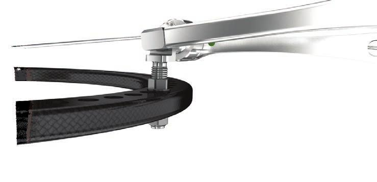
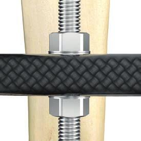
10 Hoffmann LRF Circular External Fixation Operative technique Key components Foot arches Fully assembled design for ease and speed of application Carbon fiber reinforced polymer offers strength and radiolucency Built-in hinged connection bolts allow for angular adjustment for additional construct versatility Available in 100, 120, 140, 155, 180 and 210mm diameters Foot arches are attached to rings using the M8 connection nuts. To ensure easy application, assemble foot arches on rings prior to tensioning wires. If the angle of the foot arch is changed after tensioning wires in the foot, wires may need to be re-tensioned. Caution: To maintain intended performance, carbon fiber rings and foot arches should not be re-sterilized beyond (50) autoclave cycles. 10


, use")
 M6 nuts")


 140")
 Rocker shoe mounting sites")
11 Operative technique Hoffmann LRF Circular External Fixation Key components Rocker shoes Independent shoe design allows for side-specific height adjustment when presented with an angled foot ring. Anterior and posterior shoe ends feature a 15 º slope to help facilitate normal gait. M6 connection nuts are used to attach rocker shoes to foot rings. When additional clearance between the foot ring and rocker shoe is needed (i.e. to accommodate pin / wire fixation below the surface of the foot ring), use colored washers to create height offset. Caution: Do not sandwich foot ring with (2) M6 nuts to attach rocker shoes. Use washers. If rocker shoes are indicated, take caution not to occupy mounting holes with other frame components. On the open end of the foot ring, rocker shoes are secured to the inner row of holes. Rocker shoes are not offered sterile and cannot be sterilized. Apply Rocker shoes post-operatively. Caution: Encourage patients to use caution when walking on wet or slippery surfaces. Rocker shoe sizing Max clearance = 23mm (incl. washer red 7mm) Left foot rings Dia (mm) Long rocker shoe size 100 Small rocker shoe 120 long ( ) 140 Medium rocker shoe 155 long ( ) Large rocker shoe long ( ) Rocker shoe mounting sites Short foot rings Dia (mm) Short rocker shoe size 100 Small rocker shoe 120 long ( ) 140 Medium rocker shoe 155 long ( ) Large rocker shoe long ( ) 11


12 Hoffmann LRF Circular External Fixation Operative technique Key components Spherical washer Spherical washers are designed to allow angulation of the threaded rod components within the ring. This allows threaded rods to span to rings that are not parallel or of different diameters.the angulation is achieved by adding the conical / cup shaped washer assembly to both sides of the ring/ threaded rod interface. Spherical washers are attached using the M6 connecting nuts only. The female half of the washer is applied with the grooved surface to the ring. The male half of the washer is applied second, followed by the M6 nut. Female washer Male washer M6 nut M6 nut Male washer Female washer 10 º 10 º 12 º 12 º Carbon fiber ring Aluminum ring Spherical washers can be used with both aluminum and carbon fiber rings. Rods can be angulated 12 º from neutral when aluminum rings are used. Since the carbon rings are slightly thicker, 10 º of rod angulation from neutral is possible. 12


13 Key components Operative technique Hoffmann LRF Circular External Fixation Slotted plates Slotted plates can be used to build a variety of offset component assemblies. Slotted plates are commonly used as modular ring tabs to capture threaded rods or struts that do not directly align with adjacent rings. Slotted plates are connected to rings using medium M6 connection bolts and M6 nuts. Slotted plates are designed to accommodate both 6mm and 8mm diameter components. In addition to offsetting 6mm threaded rods, slotted plates can be used to attach components such as telescopic struts and pin / wire fixation components. 8mm 8mm 8mm 45mm 13
14 Hoffmann LRF Circular External Fixation Operative technique Operative technique 14


 approaches for hinge placement are discussed: the ring block first approach and the guide wire first approach. Hinges are aligned along the joint line of the ankle (Inman s axis).")

15 Operative technique Hoffmann LRF Circular External Fixation Operative technique: Equinus foot correction External fixation correction strategies Several technique variations exist for equinus foot correction. All techniques require distraction of the ankle to protect the articular surface during correction. Gradual Correction techniques require a stable ankle at all times. It is important to note that pin and wire placement will vary by indication and surgeon preference. The steps below detail the recommended procedures for applying the Hoffmann LRF Gradual Correction components. The following construct example consists of a 2-ring tibial block, a foot ring, and a carbon fiber foot arch. It is recommended that the distal tibial ring has the same diameter as the foot ring. Two (2) approaches for hinge placement are discussed: the ring block first approach and the guide wire first approach. Hinges are aligned along the joint line of the ankle (Inman s axis). Constructs with an anterior motor are referred to as pull constructs; constructs with a posterior motor are referred to as push constructs. Caution: Due to the length limitations of the telescopic hinges, the guide wire first approach may be advantageous in certain cases because placement of the hinges is not dictated by the distance of the ring block in relation to the ankle joint. Rather, the approximate location of the ring block is dictated by the length of the hinges. "Push" construct "Pull" construct In either approach, it is important to leave at least 5-10mm of travel in the hinged telescopic struts to accomplish the final distraction. Do not mount the ring block at a distance that fully extends the length of the strut. 15


 used with wire")

 Wire bolt,")
 Utilize")

16 Hoffmann LRF Circular External Fixation Operative technique Operative technique: Equinus foot correction Recommended tension levels 50kg Tension 90kg Tension 130kg Tension Wire bolt offset adapter, long ( ) used with wire bolt short ( ) Wire bolt offset adapter, short ( ) used with wire bolt short ( ) Wires used on foot rings Wire bolt, short ( ) Wire bolt, medium ( ) Wire bolt, long ( ) Utilize counter-torque instrumentation to minimize wire bending during final tightening. 16


17 Operative technique Hoffmann LRF Circular External Fixation Operative technique: Equinus foot correction Method A Tibial ring block first approach A1. Prebuild a 2-ring tibial block with 4 threaded rods or 60mm static struts. The lower tibial ring is placed mm above the level of the ankle joint mm A2. The 1 st olive wire is an axial wire placed lateral to medial on the distal ring, mm above the level of the ankle joint. This wire will be placed on the bottom of the ring. There must be at least a 2-3cm of space between the ring and skin and the tibia is centered from medial to lateral. A C-Arm is used to ensure that the olive is flush with the bone and the wire is tensioned. The 2-ring construct can now be rotated around this wire to align the rings to the tibia (lateral view). The line of reference is the posterior cortex of the tibia. A3. The 2 nd olive wire is an axial wire placed medial to lateral at the level of the proximal ring. The wire is placed on the top surface of the proximal ring. A C-Arm visualizes the olive flush with the bone and the wire is tensioned. These first two wires lock the 2-ring tibial construct. The construct should now be assessed for position. The construct should be at right angles to the tibia (AP and Lateral View). 17

18 Hoffmann LRF Circular External Fixation Operative technique Operative technique: Equinus foot correction Method A Tibial ring block first approach If the remaining connections are to be half-pins, the tension on the two wires is loosened and the wires are simultaneously re-tensioned. Alternately, two half-pins can be placed above and below each ring. The following steps provide instruction on how to apply the frame using wires as the primary mode of fixation. In certain instances, half-pins may be preferred. A4. The 3 rd olive wire is a medial face wire placed on the bottom side of the proximal ring. This wire starts just lateral to the crest of the tibia and exits the tibia just in front of the posterior border on the medial side of the tibia. The first wire is de-tensioned and both wires are re-tensioned simultaneously. A5. The 4 th wire (smooth) is a fibular wire placed on the top of the distal ring from lateral to medial. This wire should exit through the fibula or just in front of the fibula. The first distal tibial ring wire is de-tensioned and both wires are re-tensioned simultaneously. 18


19 Operative technique Hoffmann LRF Circular External Fixation Operative technique: Equinus foot correction Method A Tibial ring block first approach A6. The stability of the tibial construct is assessed and additional connections are added as necessary. As currently constructed, the tibial block is stable in medial-lateral bending but may be unstable in anterior-posterior bending. Since equinus is a sagittal plane deformity, the construct must be stable in that plane to prevent deformation of the rings. A-P stiffness is accomplished by placing an A-P Apex-pin on either side of the distal ring, proximal ring or both. The use of A-P half-pins will provide maximum rigidity in the sagittal plane. Hinge assembly A7. Starting on the lateral side of the ankle, attach the ball-jointed end of the strut to the distal tibial ring. If necessary, the ball joints can be unlocked to accommodate for non-orthogonal orientation of the tibial ring block. Once satisfactory strut trajectory is achieved, lock the ball joint to maintain intended positioning. Unlock the quick release mechanisms to grossly adjust the strut length so that the hinge aligns exactly with the tip of the lateral malleolus. A similar hinge assembly is attached to the medial side, with the medial hinge s pivot point aligned approximately 1cm distal to the tip of the medial malleolus. Once proper alignment is achieved, all hinges, ball joints, and quick release mechanisms are verified locked to maintain desired positioning. Caution: At full extension, hinged telescopic struts can span rings that are 150mm apart or closer (including 10mm needed for final distraction). If the distance between the foot ring and distal tibial ring exceeds 140mm, threaded rods with hinge couplings can be used as an alternative. Continue with step AB1 on page 22 19


20 Hoffmann LRF Circular External Fixation Operative technique Operative technique: Equinus foot correction Method B Guide wire first approach Due to the length limitations of the hinged telescopic struts, the guide wire first approach may be advantageous because placement of the hinges is not dictated by the distance of the ring block in relation to the ankle joint. Rather, the approximate location of the ring block is dictated by the length of the hinges. In either approach, it is important to leave at least 5-10mm of travel in the hinged telescopic struts to accomplish the final distraction. Do not mount the ring block at a distance that fully extends the length of the strut. B1. A guide wire is used to define the axis of rotation of the ankle joint. If using a closed ring or ring block, slide rings onto leg first. With fluoroscopic assistance, insert a smooth wire through the talus from approximately 1cm distal to the tip of the medial malleolus aiming toward the tip of the lateral malleolus. Attach strut to ring The starting position is anterior / medial. Aim your wire in a slightely posterior / lateral direction. B2. Slide tibial ring or ring block onto the leg. Reference point for hinges Using the guide wire as a reference point for the hinges, attach the balljointed end of the struts to the distal tibial ring. To avoid interference with the hinges, the targeting wire can be cut short on either side so that the tip of the wire aligns with the hinge s pivot point. Once struts are attached, make sidespecific adjustments to the length of each strut to accommodate non-orthogonal placement of the tibial ring/ring block if necessary. The total travel possible of the Strut is 25mm. Before fixating the tibial ring / ring block, ensure that each strut is compressed with at least 10mm of length left to accomplish the final distraction. B3. Insert the first olive wire as described in prior steps (see A2) and attach the ring / ring block with fixation of choice (e.g. see steps A3 A6). 20


21 Operative technique Hoffmann LRF Circular External Fixation Operative technique: Equinus foot correction AB1. The foot ring is attached to the hinged end of the strut using the M6 connection bolts. M6 Connection bolts come in 3 different lengths and can be used in conjunction with washers to accommodate height offset of the hinge in relation to the foot ring. Utilize the hinge s counter-torque surfaces to prevent unwanted rotation of the hinge during final tightening of the connection bolts. Make sure to check the hinges range of motion by plantar and dorsiflexing the foot ring. Checking for smooth motion of the foot ring will verify that the hinges have not rotated during final tightening. The long M6 connection bolt with washers can span a 16mm gap between the foot ring and the hinge attachment sites. If the distance between these connections exceeds this length, short threaded rods and M6 connection nuts can be used to connect the hinges to the foot ring. Threaded rod used to connect hinge to foot ring. Threaded rod-to-hinge connection must be reinforced with an M6 nut. A similar hinge assembly is attached to the medial side. Once proper alignment is achieved, all hinges, ball joints, and quick release mechanisms are verified locked to maintain desired positioning. Caution: Placing hinges too far posteriorly may result in the impingement of articular cartilage, even after distraction. 21

22 Hoffmann LRF Circular External Fixation Operative technique Operative technique: Equinus foot correction To ensure easy application, the foot arch should be securely mounted to the foot ring before wires are tensioned. Attaching the foot arch a few holes back from the open end of the foot ring may help maintain a more vertical orientation of an anteriorly place motor. Foot ring fixation AB2. The 1 st foot wire is an olive wire placed lateral to medial through the calcaneal tuberosity. This wire is placed on the top of the footplate and is tensioned. Care must be taken to avoid the neurovascular structures on the medial side of the calcaneus. In some cases, more of a direct lateral to medial wire trajectory may help keep the wire in the safe zone. AB3. The 2 nd foot wire is an olive wire placed medial to lateral at the level of the metatarsal bases. This wire may actually be placed more distal to increase the lever arm for equinus correction. The wire is tensioned and the foot should now be centered in the footplate. AB4. Minding the calcaneal safe zones, the 3 rd foot wire is placed above the foot ring and enters the just in front of the achilles tendon. Wire is aimed from posterior /medial to anterior / lateral. The first calcaneal wire is de-tensioned and both wires are re-tensioned simultaneously. 22


23 Operative technique Hoffmann LRF Circular External Fixation Operative technique: Equinus foot correction AB5. The 4 th foot wire is a lateral to medial olive wire at the level of the metatarsal bases. Placement above or below the footplate is dictated by local anatomy. The first forefoot wire is de-tensioned and both wires are re-tensioned simultaneously. AB6. With the hinges aligned and fixation in place, the construct is assessed to verify unobstructed dorsiflexion - plantarflexion. An additional wire may be placed in the talus to prevent distraction though the subtalar joint. 23


24 Hoffmann LRF op tech (H-ST-2)-Proof 3 Hoffmann LRF Circular External Fixation Operative technique Alternative construct Threaded rod assembly A hinge attached to the end of a threaded rod can be used as a simple alternative to the hinged telescopic strut. Distraction can be accomplished by incrementally loosening and tightening the nuts below and above the tibial ring until the desired amount of distraction is achieved. Hinge placement methods and notes should be followed as outlined in previous sections of this guide. Reinforce the universal hinge coupling with M6 nuts to help prevent connections from loosening throughout the course of treatment Caution: Make sure to select a long enough threaded rod to allow for 10mm of distraction. One full revolution of the M6 nut equates to one millimeter of distraction. 24


25 Hoffmann LRF op tech (H-ST-2)-Proof 3 Alternative construct Operative technique Hoffmann LRF Circular External Fixation Threaded rod assembly 25


26 Hoffmann LRF op tech (H-ST-2)-Proof 3 Hoffmann LRF Circular External Fixation Operative technique Operative technique: Equinus foot correction Telescopic motor attachment AB7. Telescopic motors can be applied posteriorly (push construct) or anteriorly (pull construct) based on the degree of angulation and surgeon preference. Once the mounting approach is confirmed, the distance between motor attachment sites is measured and the appropriate length motor is selected. Based on the indication, the universal or constrained hinge coupling is securely tightened to the end of the motor. As per surgeon discretion, the equinus should be over corrected by 10 degrees if indicated. This should be taken into account when selecting the length of the telescopic motor. Caution: The shortest length motor (extra short) is 142mm fully compressed (ring-to-ring distance). Equinus deformities with 40+ degrees of plantarflexion may be difficult to treat with a posterior motor since the posterior portions of the foot ring and distal tibial ring may be too close to mount the motor in between. Consider an anterior motor approach for this degree of deformity. Caution: When mounting an anterior motor, the angle of the motor should be 30 º or less. 40 º 30 º Posterior push construct Anterior pull construct When taking the anterior motor mounting approach, the angle of the foot arch can be adjusted in preparation for the attachment of the motor. While the motor lengths overlap, selecting the longest size possible will minimize the need for motor change outs. 26


27 Hoffmann LRF op tech (H-ST-2)-Proof 3 Operative technique Hoffmann LRF Circular External Fixation Operative technique: Equinus foot correction Attachment of the motor can be done before or after final distraction of the ankle. Once the motor subassembly is assembled, the clicker end of the motor is attached to the ring using a short M8 connecting nut. To offset the attachment of the motor on the tibial block, a slotted plate can be applied to the ring using a medium M6 connection bolt and nut. On the hinged end, the M6 connecting bolts are used to attach the motor to the ring and / or foot arch. Utilize the motor s counter-torque surfaces to definitively secure each end. Before surgery is complete, confirm that access to the motor s adjustment point is not obstructed by other frame components. The dimple markers on the clicking mechanism s counting wheel should be aligned in the starting position: Single reference dimple on top portion of the counting wheel should align with the single dimple mark on the lower portion of the counting wheel. This is designed to allow the patient to keep track of quarter millimeter adjustments by starting them in the initial start position. 27


28 Hoffmann LRF op tech (H-ST-2)-Proof 3 Hoffmann LRF Circular External Fixation Operative technique Operative technique: Equinus foot correction Final distraction AB8. Distraction is necessary to protect the articular cartilage during equinus correction. The amount of distraction needed is based on the specific indications of the patient and surgeon discretion. The distraction is done intraoperatively on the OR table. 1. Distraction of the struts needs to be done progressively. For example, the quick release on the medial strut should remained locked while the quick release on the lateral strut is unlocked and manually distracted 2-3mm by pulling on the foot ring assembly. The lateral strut is locked to hold the initial distraction while the medial strut is adjusted 2-3mm. Repeat adjustments until the joint space is uniformly distracted to the appropriate distance. 2. Once the desired amount of distraction is achieved and confirmed, the quick release mechanisms are relocked to maintain the distraction 3. If needed, fine length adjustment features of the hinged telescopic strut can be used until the desired amount of distraction is achieved. When taking this approach, first confirm the quick release mechanisms are locked. Adjust each strut one at a time, keeping one strut fully locked while the other is being adjusted. One full revolution of the strut equals 2mm of distraction. Caution: After distraction, confirm that hinges are aligned on the ankle joint s center axis of rotation and ensure that all component interfaces are definitively locked tight. Distracted joint space 28


 represents 2mm of motor compression / distraction.")
, the clicking mechanism is turned counter-clockwise.")
 1/4mm adjustments (4 clicks).")

 The reference dimple on the top of the clicker should be aligned with the single dimple marker on the lower")
 The reference markers found on the counting wheel of the adjustment driver should match the dimple reference markers on the motor s clicker.")
29 Hoffmann LRF op tech (H-ST-2)-Proof 3 Operative technique Hoffmann LRF Circular External Fixation Operative technique: Equinus foot correction Post operative adjustments During the post-op gradual adjustment phase, the patient can utilize the manual adjustment instrument to actuate the motor and slowly dorsiflex the foot. The counting wheel on the adjustment instrument can be used to keep track of daily corrections. Posterior push construct Deformity before correction Anterior pull construct Caution: Fast adjustment rates may lead to complications including soft tissue / neurovascular damage. Rates of correction are indication-specific and may vary patient-to-patient. Rates of correction may also differ when taking an anterior motor approach vs. a posterior motor approach. Once the custom adjustment schedule is devised by the surgeon, the patient or caregiver can execute gradual corrective adjustments as prescribed. One full revolution of the clicking mechanism (8 1/4mm clicks) represents 2mm of motor compression / distraction. To compress the length of the motor (as performed with an anterior pull construct), the clicking mechanism is turned clockwise. To distract the motor (as performed with a posterior push construct), the clicking mechanism is turned counter-clockwise. Take caution not to rotate the clicking mechanism while applying the adjustment driver. Typically the 1mm of motor travel is broken up into (4) 1/4mm adjustments (4 clicks). Caution: When making adjustments, use caution not to erroneously adjust the wrong frame components. Only make adjustments to the prescribed motor. Corrected deformity Frames reinforced for weight bearing After a full day of adjustment (4 clicks = 1mm of motor travel), the correction should be verified by the following: 1) The reference dimple on the top of the clicker should be aligned with the single dimple marker on the lower half of the counting wheel. This represents a half revolution of the clicker (corresponding to 1mm of travel). 2) The reference markers found on the counting wheel of the adjustment driver should match the dimple reference markers on the motor s clicker. After a full day (4 clicks) the adjustment instrument should be adjusted to the single dimple marker. 3) Using the correction schedule as a reference, confirm that the motor s lengthening scale reads the appropriate number. For example, if the motor is being compressed and is at 305mm at the start of the day, after 4 clicks, the scale should read 304mm. This will also confirm that the adjustment is taking place in the proper direction. 29


30 Hoffmann LRF op tech (H-ST-2)-Proof 3 Hoffmann LRF Circular External Fixation Operative technique Operative technique: Equinus foot correction Reinforcing frames for weight bearing Partial weight bearing with crutches or walker can begin during the last 10 degrees of correction. Full weight bearing can ensue when the deformity is fully corrected. At this point, the frame should be reinforced with additional support assemblies to accommodate an increased amount of loading. Caution: Once correction is achieved and patients are allowed to weight bear, an additional static telescopic strut or threaded rod assembly is strongly recommended for increased construct stability. Anterior support assembly using hinges and threaded rods Posterior support with universal telescopic strut 30


31 Hoffmann LRF op tech (H-ST-2)-Proof 3 Operative technique Hoffmann LRF Circular External Fixation Operative technique: Equinus foot correction Telescopic motor strut change out procedure When executing a Gradual Correction procedure on a large angular deformity, there may be a need to change the frame s motor once all usable travel is consumed. When exchanging struts, the surgeon must take care not to lose the correction that has already been achieved during prior days of correction. Before removing a fully expended motor, the frame must be stabilized and reinforced to preserve the amount of correction already achieved. Several approaches exist for this procedure. Supplemental Hoffmann components should be used to further stabilize the frame, especially if lockable hinges are not being used. On the posterior portion of the frame, a universal telescopic strut can be used to span the rings proximal and distal to the joint space or osteotomy. Be sure that the supplemental strut is securely tightened to the rings with the appropriate connecting nuts and also make ensure that all ball joints and quick release mechanisms are securely locked. Posterior fixation with universal telescopic strut 31


32 Hoffmann LRF op tech (H-ST-2)-Proof 3 Hoffmann LRF Circular External Fixation Operative technique Operative technique: Equinus foot correction Telescopic motor strut change out procedure Alternatively, a simple hinge / threaded rod assembly can be built and used in a similar fashion. When taking this approach, confirm that the coupling is securely tightened to the ring and threaded rods using M6 connection nuts and bolts. Also confirm that the hinge coupling is locked. Another available option is to utilize the Hoffmann 8mm posts and rods to span and stabilize the frame during a strut change out. Again, before exchanging the motor, ensure that all supplemental fixation components are securely locked. When assembling/applying the frame, select the longest strut possible to minimize the number of strut change outs. During correction, the motor s travel will be used. Once the original motor is fully expended, the next size motor can replace it in a strut change out as described above. Supplemental fixation is applied to the frame during the change out, spanning the reference and moving rings. Confirm all connections and sub-assemblies are securely locked and stable. Posterior fixation with threaded rod Anterior strut prior to correction Posterior fixation with Hoffmann 3 components Anterior strut fully expended 32


33 Hoffmann LRF op tech (H-ST-2)-Proof 3 Operative technique Hoffmann LRF Circular External Fixation Operative technique: Equinus foot correction Telescopic motor strut change out procedure Once hinges are locked and the frame is securely reinforced, the original long telescopic motor is removed. The medium telescopic motor is now attached in the fully extended position in place of the original long motor. Once the new motor is installed, the supplement fixation is removed and correction can now continue until the deformity is fully corrected or until the next strut change out is required. 33
34 Hoffmann LRF op tech (H-ST-2)-Proof 3 Hoffmann LRF Circular External Fixation Operative technique Notes: 34
35 Hoffmann LRF op tech (H-ST-2)-Proof 3 Notes: Operative technique Hoffmann LRF Circular External Fixation 35
36 Hoffmann LRF op tech (H-ST-2)-Proof 3 Trauma & Extremities This document is intended solely for the use of healthcare professionals. A surgeon must always rely on his or her own professional clinical judgment when deciding whether to use a particular product when treating a particular patient. Stryker does not dispense medical advice and recommends that surgeons be trained in the use of any particular product before using it in surgery. The information presented is intended to demonstrate a Stryker product. A surgeon must always refer to the package insert, product label and/or instructions for use, including the instructions for Cleaning and Sterilization (if applicable), before using any Stryker product. Products may not be available in all markets because product availability is subject to the regulatory and/or medical practices in individual markets. Please contact your Stryker representative if you have questions about the availability of Stryker products in your area. Stryker Corporation or its divisions or other corporate affiliated entities own, use or have applied for the following trademarks or service marks: Apex, Hoffmann, Stryker. All other trademarks are trademarks of their respective owners or holders. Content ID: H-ST-2_Rev. 2, Copyright 2016 Stryker Manufacturer: Stryker GmbH Bohnackerweg Selzach Switzerland stryker.com
Hoffmann LRF Circular External Fixation. Operative technique
 Hoffmann LRF Circular External Fixation Operative technique Hoffmann LRF Circular External Fixation Operative technique Hoffmann LRF Circular External Fixation Contents 1. Indications and contraindications...
EasyStep. Operative technique
 Operative technique EasyStep - Step staple This publication sets forth detailed recommended procedures for using Stryker Osteosynthesis devices and instruments. It offers guidance that you should heed,
Workshop Outline. Pre-operative planning
 Workshop Objective To build and apply the True/Lok TM circular external fixator frame for correction of the Charcot forefoot deformity (Lisfranc fracture dislocation) Workshop Outline Pre-operative planning
OPERATIVE TECHNIQUE ANKLE ARTHRODESIS USING THE TRUELOK RING FIXATION SYSTEM
 OPERATIVE TECHNIQUE ANKLE ARTHRODESIS USING THE TRUELOK RING FIXATION SYSTEM 1 INTRODUCTION 2 COMPONENTS REQUIRED 2 CLEANING AND STERILIZATION 2 INDICATIONS 3 ASSEMBLY 5 PATIENT POSITIONING 5 APPLICATION
Asnis. Micro Cannulated screw system. Xpress operative technique
 Asnis Micro Cannulated screw system Xpress operative technique Asnis Micro Cannulated screw system Table of contents Indications, precautions & contraindications 3 Operative technique 4 This publication
Introduction to the Taylor Spatial Frame Hardware. Trademark of Smith & Nephew. Certain marks Reg. US Pat. & TM Off.
 Introduction to the Taylor Spatial Frame Hardware Trademark of Smith & Nephew. Certain marks Reg. US Pat. & TM Off. What is the Taylor Spatial Frame? Next generation circular fixator capable of 6 axes
Knee spanning solutions
 Knee spanning solutions System features Indications Intended to be used on adults or pediatric patients as required for fracture fixation (open or closed); post-traumatic joint contracture which has resulted
Foot & Ankle. Smart Toe II. Intramedullary Implant. Operative Technique. Foot & Ankle
 Foot & Ankle Smart Toe II Intramedullary Implant Operative Technique Foot & Ankle Smart Toe This publication sets forth detailed recommended procedures for using Stryker Osteosynthesis devices and instruments.
Surgical Technique. Computer Assisted Circular Ring Fixation System for the Treatment of Limb Deformity Correction
 Computer Assisted Circular Ring Fixation System for the Treatment of Limb Deformity Correction Surgical Technique This publication is not intended for distribution in the USA. Image intensifier control
Zimmer Trabecular Metal Ankle Interpositional Spacer and Trabecular Metal Ankle Fusion Spacer
 Zimmer Trabecular Metal Ankle Interpositional Spacer and Trabecular Metal Ankle Fusion Spacer Surgical Technique 2 Zimmer Trabecular Metal Ankle Interpositional Spacer and Trabecular Metal Ankle Fusion
LCP Medial Distal Tibia Plate, without Tab. The Low Profile Anatomic Fixation System with Angular Stability and Optimal Screw Orientation.
 LCP Medial Distal Tibia Plate, without Tab. The Low Profile Anatomic Fixation System with Angular Stability and Optimal Screw Orientation. Technique Guide LCP Small Fragment System Table of Contents Introduction
Hoffmann II External Fixation System
 Hoffmann II External Fixation System Modular System for Long Bones Pelvis Introduction In 1938, Raoul Hoffmann, a surgeon from Geneva, Switzerland, designed a revolutionary External Fixation System. The
Knee Surgical Technique
 Knee Surgical Technique COMPASS Universal Hinge by Jimmy Tucker, M.D. Orthopaedic Surgeon Director, Arkansas Sports Medicine, P.A. Little Rock, Arkansas Table of contents Design features 3 Indications
Technique Guide. The Distraction Osteogenesis Ring System. Nonarticular tibia frame.
 Technique Guide The Distraction Osteogenesis Ring System. Nonarticular tibia frame. Table of Contents Introduction The Distraction Osteogenesis Ring System 2 AO Principles 4 Indications 5 Surgical Technique
4Fusion. Shape Memory Implant. Operative Technique
 4Fusion Shape Memory Implant Operative Technique 4Fusion This publication sets forth detailed recommended procedures for using Stryker devices and instruments. It offers guidance that you should heed,
CableFIX Xpress Carpometacarpal Fixation System. Operative technique
 CableFIX Xpress Carpometacarpal Fixation System Operative technique CableFIX Xpress Carpometacarpal Fixation System CableFIX Xpress Carpometacarpal Fixation System Contents 1. Indications and contraindications...
Hoffmann II Compact External Fixation System
 Trauma Hoffmann II Compact External Fixation System Modular System for Upper Extremity Foot Introduction In 1938, Raoul Hoffmann, a surgeon from Geneva, Switzerland, designed a revolutionary External Fixation
VariAx Compression Plating System. Operative technique
 VariAx Compression Plating System Operative technique VariAx Compression Plating System Operative technique VariAx Compression Plating System Contents 1. Introduction... 3 2. Indications, MR safety information
Technique Guide. The Distraction Osteogenesis Ring System. Intra-articular distal tibia frame.
 Technique Guide The Distraction Osteogenesis Ring System. Intra-articular distal tibia frame. Table of Contents Introduction The Distraction Osteogenesis Ring System 2 MRI Information 4 AO Principles 5
Surgical Technique. CONQUEST FN Femoral Neck Fracture System
 Surgical Technique CONQUEST FN Femoral Neck Fracture System Table of Contents Introduction... 3 Indications... 3 Product Overview... 4 Surgical Technique... 5 Patient Positioning... 5 Reduce the Fracture...
Hoffmann II Micro External Fixation System. Indications for the Hand
 Hoffmann II Micro External Fixation System Indications for the Hand Features & Benefits The instrumentation is Simple and User-Friendly, and the system is Color Coded, so there is no lost time or confusion
LCP Anterolateral Distal Tibia Plate 3.5. The low profile anatomic fixation system with optimal plate placement and angular stability.
 LCP Anterolateral Distal Tibia Plate 3.5. The low profile anatomic fixation system with optimal plate placement and angular stability. Technique Guide LCP Small Fragment System Table of Contents Introduction
3. PATIENT POSITIONING & FRACTURE REDUCTION 3 8. DISTAL GUIDED LOCKING FOR PROXIMAL NAIL PROXIMAL LOCKING FOR LONG NAIL 13
 Contents IMPLANT FEATURES 2 1. INDICATIONS 3 2. PRE-OPERATIVE PLANNING 3 3. PATIENT POSITIONING & FRACTURE REDUCTION 3 4. INCISION 4 5. ENTRY POINT 4-6 6. PROXIMAL NAIL INSERTION 6-7 7. PROXIMAL LOCKING
Conventus CAGE PH Surgical Techniques
 Conventus CAGE PH Surgical Techniques Conventus Orthopaedics The Conventus CAGE PH (PH Cage) is a permanent implant comprised of an expandable scaffold, made from nitinol and titanium, which is deployed
Surgical Technique. Customer Service:
 Patent and Patent Pending CAUTION: Federal Law (USA) restricts this device to sale by or on the order of a physician. INDICATIONS FOR USE The Axis Charcot Fixation System in diameters of 5.5, 6.5 and 7.5mm
Femur. Monoaxial Locking Plate System. Operative Technique. Distal Lateral Femur Universal Holes Targeting Instrumentation.
 Femur AxSOS 3 Titanium Monoaxial Locking Plate System Femur Fractures Operative Technique Distal Lateral Femur Universal Holes Targeting Instrumentation This publication sets forth detailed recommended
CREATED FOR SUPPORT. DESIGNED FOR VERSATILITY. CONSTRUCT GUIDE
 CREATED FOR SUPPORT. DESIGNED FOR VERSATILITY. CONSTRUCT GUIDE A SYSTEM DESIGNED FOR DIVERSE NEEDS Proper reconstruction and healing demands structure as well as options. That s why we designed the ACE-Fischer
TransFx External Fixation System Large and Intermediate Surgical Technique
 TransFx External Fixation System Large and Intermediate Surgical Technique TransFx External Fixation System Large and Intermediate Surgical Technique 1 Surgical Technique For TransFx External Fixation
AxSOS. Locking Plate System. Operative Technique. Small Fragment Basic Fragment
 AxSOS Locking Plate System Operative Technique Small Fragment Basic Fragment Stryker Plating Contents Page 1. Introduction 4 2. Features & Benefits 5 4 and 5 Compression Plates 5 Reconstruction and 1/3
M.I.S. MAKE IT SMART IN ONE SYSTEM. Surgical Technique. Hip Knee Spine Navigation
 M.I.S. MAKE IT SMART IN ONE SYSTEM Surgical Technique Hip Knee Spine Navigation M.U.S.T. Mini Open Surgical Technique Hip Knee Spine Navigation 2 C O N T E N T S 1 INTRODUCTION 4 2 SURGICAL TECHNIQUE 5
AxSOS Locking Plate System
 AxSOS Locking Plate System Operative Technique Small Fragment Basic Fragment 1 2 Contents Page 1. Introduction 4 2. Features & Benefits 5 4 and 5mm Compression Plates 5 Reconstruction and 1/3 Tubular Locking
Constrained Posterior Stabilized (CPS) Surgical Technique
 Surgical Technique") Constrained Posterior Stabilized (CPS) Surgical Technique Constrained Posterior Stabilized (CPS) Surgical Technique INTRO Introduction The Constrained Posterior Stabilized (CPS) articular surfaces can
Constrained Posterior Stabilized (CPS) Surgical Technique Constrained Posterior Stabilized (CPS) Surgical Technique INTRO Introduction The Constrained Posterior Stabilized (CPS) articular surfaces can
Triathlon Knee System. Universal Baseplate Surgical Protocol
 Triathlon Knee System Universal Baseplate Surgical Protocol Table of Contents Acknowledgments..........................................................2 Introduction...............................................................2
Surgical Technique 4.5/8.5MM BEAMING SYSTEM. Customer Service:
 Patent and Patent Pending CAUTION: Federal Law (USA) restricts this device to sale by or on the order of a physician. INDICATIONS FOR USE The 4.5/8.5 screw system is intended for fixation arthrodesis of
VLIFT System Overview. Vertebral Body Replacement System
 VLIFT System Overview Vertebral Body Replacement System VLIFT System System Description The VLIFT Vertebral Body Replacement System consists of a Distractible In Situ (DIS) implant, which enables the surgeon
EGR Endoscopic Gastrocnemius Recession. Operative technique
 Endoscopic Gastrocnemius Recession Operative technique Endoscopic Gastrocnemius Recession Table of contents Introduction 3 Operative technique 4 This publication sets forth detailed recommended procedures
Hoffmann II Micro External Fixation System
 Trauma Hoffmann II Micro External Fixation System Indications for the Hand Components 9 3 4 5 1 2 7 8 6 1 Hoffmann II Micro Multi-Pin Clamp 2 Hoffmann II Micro 90 Multi-Pin Clamp 3 Hoffmann II Micro Rod
Biomet. Vision Pin-To-Bar System. Surgical Technique. Calcaneal Reduction Frame
 Biomet Vision Pin-To-Bar System Surgical Technique Calcaneal Reduction Frame One Surgeon. One Patient. Over 1 million times per year, Biomet helps one surgeon provide personalized care to one patient.
Hoffmann II Compact External Fixation System. Modular System for
 Hoffmann II Compact External Fixation System Modular System for Introduction In 1938, Raoul Hoffmann, a surgeon from Geneva, Switzerland, designed a revolutionary External Fixation System. The basic features
Technique Guide. 3.5 mm LCP Low Bend Medial Distal Tibia Plate Aiming Instruments. Part of the 3.5 mm LCP Percutaneous Instrument System.
 Technique Guide 3.5 mm LCP Low Bend Medial Distal Tibia Plate Aiming Instruments. Part of the 3.5 mm LCP Percutaneous Instrument System. Table of Contents Introduction 3.5 mm LCP Low Bend Medial Distal
System. Humeral Nail. Surgical Technique
 System Humeral Nail Surgical Technique Contents IMPLANT FEATURES 2 1. INDICATIONS 3 2. PRE-OPERATIVE PLANNING 3 3. PATIENT POSITIONING & FRACTURE REDUCTION 3 4. INCISION 4 5. ENTRY POINT 4-6 6. PROXIMAL
TRUMATCH PERSONALIZED SOLUTIONS with the SIGMA High Performance Instruments
 TRUMATCH PERSONALIZED SOLUTIONS with the SIGMA High Performance Instruments Resection Guide System SURGICAL TECHNIQUE RESECTION GUIDE SURGICAL TECHNIQUE The following steps are an addendum to the SIGMA
External Fixator Brochure
 External Fixator Brochure Response Ortho is a global orthopaedic trauma solutions manufacturer offering premium products created under its founding principles of innovation, excellence by design and functional
Foot & Ankle. EasyClip. Osteosynthesis Compression Staples. Foot & Ankle
 Foot & Ankle EasyClip Osteosynthesis Compression Staples Foot & Ankle Operative Technique EasyClip Osteosynthesis Compression Staples 2 This publication sets forth detailed recommended procedures for using
PAL Pelvic Alignment Level
 PAL Pelvic Alignment Level Surgical Protocol For consistency during surgery Pelvic Alignment Level (PAL) Features Pelvic Alignment Level Surgical Protocol To Table To Floor 1. Patient Positioning & Preparation
DFS STANDARD FIXATOR DFS ANKLE CLAMP DFS T-CLAMP
 DFS STANDAD FIXATO DFS ANKLE CLAMP DFS T-CLAMP SUGICAL TECHNIQUE Dr. James V. Nepola Professor of Orthopaedics University of Iowa Hospitals and Clinics Iowa City, Iowa Patent No. 5,662,650 C ontents DynaFix
Technique Guide. 3.5 mm LCP Low Bend Medial Distal Tibia Plates. Part of the Synthes locking compression plate (LCP) system.
 system.") Technique Guide 3.5 mm LCP Low Bend Medial Distal Tibia Plates. Part of the Synthes locking compression plate (LCP) system. Table of Contents Introduction 3.5 mm LCP Low Bend Medial Distal Tibia Plates
Technique Guide 3.5 mm LCP Low Bend Medial Distal Tibia Plates. Part of the Synthes locking compression plate (LCP) system. Table of Contents Introduction 3.5 mm LCP Low Bend Medial Distal Tibia Plates
Surgical Technique Guide
 Guide CAUTION: Federal Law (USA) restricts this device to sale by or on the order of a physician. INDICATIONS FOR USE The Align Anterior Ankle Fusion Plate is intended to facilitate arthrodesis of the
TIPMED EXTERNAL FIXATION SYSTEMS
 TIPMED EXTERNAL FIXATION SYSTEMS ANATOMICAL LOCATIONS FOR EXTERNAL FIXATION SYSTEMS Humeral Dynamic Axial Fixator Elbow Fixator Pelvic Dynamic Axial Fixator Pennig Wrist Fixator Hand Fixator Finger Fixator
Technique Guide. Midface Distractor System. For the temporary stabilization and gradual lengthening of the cranial or midfacial bones.
 Technique Guide Midface Distractor System. For the temporary stabilization and gradual lengthening of the cranial or midfacial bones. Table of Contents Introduction Midface Distractor System 2 Indications
Distal Cut First Femoral Preparation
 Surgical Technique Distal Cut First Femoral Preparation Primary Total Knee Arthroplasty LEGION Total Knee System Femoral preparation Contents Introduction...3 DCF femoral highlights...4 Preoperative planning...6
Biomet Multi-Axial Correction (MAC) System Correction Atlas
 System Correction Atlas") Biomet Multi-Axial Correction (MAC) System Correction Atlas Demonstrated with the XS MAC on a Left Tibia (CORA Centric Approach) Introduction... Page 1 Indications/ Contraindictions... Page 1 MAC Module
Biomet Multi-Axial Correction (MAC) System Correction Atlas Demonstrated with the XS MAC on a Left Tibia (CORA Centric Approach) Introduction... Page 1 Indications/ Contraindictions... Page 1 MAC Module
Clinical. Solutions. Synthes Solutions. Foot and Ankle.
 Clinical Solutions Foot and Ankle. Foot and Ankle. Fractures of the tibial shaft Fractures of the distal fibula Fractures of the distal tibia Fractures and osteotomies of the calcaneus Arthrodesis Fractures,
Triathlon Knee System Universal Baseplate Surgical Protocol
 Triathlon Knee System Universal Baseplate Surgical Protocol Triathlon Knee System Universal Baseplate Surgical Protocol Table of Contents Acknowledgments... 2 Introduction... 2 Assembly Instructions...
TRK REVISION KNEE Surgical Technique
 1 TRK REVISION KNEE Surgical Technique 1. 2. 3. 4. 5. 6. 7. 8. 9. 10. INTERCONDYLAR RESECTION...... page FEMORAL STEM...... page NON CEMENTED FEMORAL STEM...... page TRIAL FEMORAL COMPONENTS...... page
TransFx External Fixation System Large and Intermediate Surgical Technique
 TransFx External Fixation System Large and Intermediate Surgical Technique Choice, Simplicity, Transition TransFx External Fixation System Large and Intermediate Surgical Technique 1 Surgical Technique
Pocket Guide. Version 4.1: Fracture reduction and deformity correction software
 Pocket Guide www.spatialframe.com Version 4.1: Fracture reduction and deformity correction software Shoulder bolt Master tab Strut 5 Strut 1 Strut 6 Strut 4 Strut 2 Strut 3 ID band Figure 1 Frame assembly
Locking Radial Head Plates
 Locking Radial Head Plates Locking Radial Head Plates Since 1988, Acumed has been designing solutions to the demanding situations facing orthopaedic surgeons, hospitals and their patients. Our strategy
SALVATION 3Di. Plating System SURGICAL TECHNIQUE
 SALVATION 3Di Plating System SURGICAL TECHNIQUE Contents Chapter 1 4 Introduction Chapter 2 5 Intended use 5 Indications 5 Contraindications Chapter 3 6 Device Description Chapter 4 7 Preoperative Planning
The Flower Medial Column Fusion Plate
 The Flower Medial Column Fusion Plate PROCEDURE GUIDE www.flowerortho.com The Flower Foot & Ankle Application NC FUSION PLATE 2-HOLE COMPRESSION PLATE TMT FUSION PLATE LAPIDUS FUSION PLATE COMPRESSION
Foot & Ankle T2. Ankle Arthrodesis Nail. Foot & Ankle
 Foot & Ankle T2 Ankle Arthrodesis Nail Operative Technique Foot & Ankle 1 Ankle Arthrodesis Nailing System This publication sets forth detailed recommended procedures for using Stryker devices and instruments.
LUMBAR POSTERIOR MINIMALLY INVASIVE SYSTEM. Surgical Technique
 LUMBAR POSTERIOR MINIMALLY INVASIVE SYSTEM Surgical Technique Joint Spine Sports Med M.U.S.T. Mini Open Surgical Technique Joint Spine Sports Med CAUTION Federal law (USA) restricts this device to sale
Large External Fixator Delta Frame Ankle Bridge. Using pin clamps with outrigger posts.
 Large External Fixator Delta Frame Ankle Bridge. Using pin clamps with outrigger posts. Technique Guide Part of the Large External Fixation System Large External Fixator Delta Frame Ankle Bridge Technique
Cervical Solutions. Optio-C Anterior Cervical Plate. with Allograft/Autograft. Surgical Technique Guide
 Cervical Solutions Optio-C Anterior Cervical Plate with Allograft/Autograft Surgical Technique Guide 2 Optio-C Anterior Cervical Plate with Allograft/Autograft Surgical Technique Guide The Optio-C System
External Skeletal Fixation (ESF)
") External Skeletal Fixation (ESF) Technique for fracture repair in animals Introduction External Skeletal Fixation is a versatile and effective technique for fracture repair in animals, rigidly stabilizing
External Skeletal Fixation (ESF) Technique for fracture repair in animals Introduction External Skeletal Fixation is a versatile and effective technique for fracture repair in animals, rigidly stabilizing
Surgical Technique. Distal Radius and Foot
 Surgical Technique Distal Radius and Foot JET-X BAR Unilateral Fixator Distal Radius and Foot Surgical Technique Contents Design Features...2 Distal Radius Surgical Technique Indications...10 Surgical
Zimmer NexGen MIS Tibial Component. Cemented Surgical Technique IMAGE TO COME
 Zimmer NexGen MIS Tibial Component Cemented Surgical Technique IMAGE TO COME Zimmer NexGen MIS Tibial Component Cemented Surgical Technique 1 Zimmer NexGen MIS Tibial Component Cemented Surgical Technique
Zimmer NexGen Trabecular Metal Tibial Tray
 Zimmer NexGen Trabecular Metal Tibial Tray Surgical Technique Zimmer NexGen Trabecular Metal Tibial Tray Surgical Technique Give Bone A Solid Hold Zimmer NexGen Trabecular Metal Tibial Tray Surgical Technique
Large External Fixator Delta Frame Ankle Bridge. For staged fixation of the distal tibia.
 Large External Fixator Delta Frame Ankle Bridge. For staged fixation of the distal tibia. Technique Guide Part of the Large External Fixation System Large External Fixator Delta Frame Ankle Bridge Technique
OPERATIVE TECHNIQUE. Knee Hinge (LRS Advanced System)
") OPERTIVE TECHNIQUE Knee Hinge (LRS dvanced System) 1 1 2 4 6 INTRODUCTION INDICTIONS FETURES ND BENEFITS EQUIPMENT REQUIRED KNEE HINGE SSEMBLY 8 17 TRUM KNEE DISLOCTION Orthofix wishes to thank the following
OPERTIVE TECHNIQUE Knee Hinge (LRS dvanced System) 1 1 2 4 6 INTRODUCTION INDICTIONS FETURES ND BENEFITS EQUIPMENT REQUIRED KNEE HINGE SSEMBLY 8 17 TRUM KNEE DISLOCTION Orthofix wishes to thank the following
External Fixation Patient Education Guide
 External Fixation Patient Education Guide Hoffmann LRF Next Generation External Fixation Team Contacts Surgery Date: Targeted Removal Date: Orthopaedic Surgeon: Name: Email: Telephone Number: Emergency/After
CANNULINK. Intraossous Fixation System SURGICAL TECHNIQUE
 CANNULINK Intraossous Fixation System SURGICAL TECHNIQUE Contents Chapter 1 4 Introduction The CANNULINK Advantage Indications for Use Preoperative Planning Chapter 2 5 Surgical Technique CANNULINK Standard
Zimmer MIS Periarticular 3.5mm Proximal Tibial Locking Plate
 Zimmer MIS Periarticular 3.5mm Proximal Tibial Locking Plate Surgical Technique The Science of the Landscape Zimmer MIS Periarticular 3.5mm Proximal Tibial Locking Plate Surgical Technique 1 Zimmer MIS
Threshold Pedicular Fixation System Surgical Technique
 Threshold Pedicular Fixation System Surgical Technique Table of Contents Patient Preparation and Positioning... 2 Determining Incision Location... 3 Assembling the Cannulated Awl... 4 Guide Wire Placement...
OBSOLETED. LCP Medial Distal Tibia Plate, without Tab. The Low Profile Anatomic Fixation System with Angular Stability and Optimal Screw Orientation.
 LCP Medial Distal Tibia Plate, without Tab. The Low Profile Anatomic Fixation System with Angular Stability and Optimal Screw Orientation. Surgical Technique LCP Small Fragment System This publication
Monotube Triax. External Fixation System. External Fixation. Operative Technique
 Monotube Triax External Fixation System Operative Technique External Fixation 1 Monotube Triax This publication sets forth detailed recommended procedures for using Stryker Osteosynthesis devices and instruments.
The Vilex FUZETM. Dual Thread Screw & Intramedullary Nail in One Implant. The Ultimate TTC Arthrodesis Internal Fixator
 The Vilex FUZETM Dual Thread Screw & Intramedullary Nail in One Implant The Ultimate TTC Arthrodesis Internal Fixator Introduction The Vilex FUZE TM TTC Arthrodesis Compression Nail combines the attributes
LCP Distal Tibia Plate
 Surgical Technique LCP Locking Compression Plate Original Instruments and Implants of the Association for the Study of Internal Fixation AO/ASIF Table of contents Indications 3 Implants/Instruments 5 Surgical
OPERATIVE TECHNIQUE. The Ring Fixator System. The Sheffield Ring Fixator - Limb Reconstruction. and Complex Trauma. By Prof. M.
 OPERATIVE TECHNIQUE 12 The Ring Fixator System Part C: The Sheffield Ring Fixator - Limb Reconstruction and Complex Trauma By Prof. M. Saleh CONTENTS Page N INTRODUCTION...................................................................................................................................
Hoffmann 3 Modular External Fixation. Operative technique
 Hoffmann 3 Modular External Fixation Operative technique Hoffmann 3 External Fixation Contents Indications and contraindications............... 4 Technical details & MRI Information.... 5 Components...
TRUMATCH PERSONALIZED SOLUTIONS with the SIGMA High Performance Instruments
 TRUMATCH PERSONALIZED SOLUTIONS with the SIGMA High Performance Instruments Pin Guide System SURGICAL TECHNIQUE PIN GUIDE SURGICAL TECHNIQUE The following steps are an addendum to the SIGMA High Performance
Surgical Technique. Anterolateral and Medial Distal Tibia Locking Plates
 Surgical Technique Anterolateral and Medial Distal Tibia Locking Plates PERI-LOC Periarticular Locked Plating System Anterolateral and Medial Distal Tibia Locking Plates Surgical Technique Contents Product
EXTERNAL FIXATION SYSTEM
 EXTERNAL FIXATION SYSTEM 2 3 1 4 5 1. DJD II Body 2. Humeral Guide 3. Pin Insertion Guides 4. Hoffmann II Compact Instruments 5. Hoffmann II Compact Components and Apex Pins 2 Overview The DJD II is a
Monolateral External Fixation System for Trauma and Orthopaedics
 MEFiSTO Monolateral External Fixation System for Trauma and Orthopaedics Surgical Technique Original Instruments and Implants of the Association for the Study of Internal Fixation AO/ASIF MEFiSTO Table
TrueSight Personalized Planning & Targeting System. Operative technique
 TrueSight Personalized Planning & Targeting System Operative technique TrueSight Personalized Planning & Targeting System Contents Introduction.... 2 Indications and contraindications... 3 Design rationale...
CHARLOTTE. 7.0 Multi-Use Compression Screw System SURGICAL TECHNIQUE
 CHARLOTTE 7.0 Multi-Use Compression Screw System SURGICAL TECHNIQUE Contents Chapter 1 1 Chapter 2 2 Chapter 3 3-9 Chapter 4 10-12 Appendix A 13-14 Design Rationale Screw Behavior Surgical Technique Procedure
Mandible External Fixator II. Provides treatment for fractures of the maxillofacial area.
 Mandible External Fixator II. Provides treatment for fractures of the maxillofacial area. Technique Guide This publication is not intended for distribution in the USA. Instruments and implants approved
QUICK REFERENCE GUIDE. The XCaliber Meta-Diaphyseal Fixator
 17 The XCaliber Meta-Diaphyseal Fixator GENERAL POINTS The XCaliber Fixator is made of radiolucent material for unobstructed X-ray visualization. The metallic bolts and the cam and bush of each ball-joint,
TABLE OF CONTENTS. 2 (8144 Rev 2)
") 1 (8144 Rev 2) TABLE OF CONTENTS Introduction Conventus CAGE TM - Proximal Humerus...3 Indications and Contraindications...4 Surgical Summary...5 Patient Positioning & Approach...6 Surgical Technique Plate
1 (8144 Rev 2) TABLE OF CONTENTS Introduction Conventus CAGE TM - Proximal Humerus...3 Indications and Contraindications...4 Surgical Summary...5 Patient Positioning & Approach...6 Surgical Technique Plate
Arthrodesis of the Ankle
 TM Arthrodesis of the Ankle Plantar View of the Foot 1. Make a lateral incision to expose the tibia-talus joint and the talo-calcaneal joint. Prepare the arthrodesis sites surgically with a rasp or an
Silicone PIP, MCP & MCP-X (PreFlex)
") Silicone PIP, MCP & MCP-X (PreFlex) Finger Joint Arthroplasty Operative Technique Silicone PIP Silicone MCP Silicone PreFlex (MCP-X) Stryker Disclaimer This publication sets forth detailed recommended
Silicone PIP, MCP & MCP-X (PreFlex) Finger Joint Arthroplasty Operative Technique Silicone PIP Silicone MCP Silicone PreFlex (MCP-X) Stryker Disclaimer This publication sets forth detailed recommended
2.7 mm/3.5 mm Variable Angle LCP. Ankle Trauma System
 Part of the DePuy Synthes Variable Angle Locking Compression Plate (VA LCP ) System 2.7 mm/3.5 mm Variable Angle LCP Ankle Trauma System Surgical Technique Table of Contents Introduction 2.7 mm/3.5 mm
Arcos Interlocking Distal Stem. Surgical Technique Addendum to the Arcos Modular Femoral Revision System
 Arcos Interlocking Distal Stem Surgical Technique Addendum to the Arcos Modular Femoral Revision System One Surgeon. One Patient. Over 1 million times per year, Biomet helps one surgeon provide personalized
Zimmer Small Fragment Universal Locking System. Surgical Technique
 Zimmer Small Fragment Universal Locking System Surgical Technique Zimmer Small Fragment Universal Locking System 1 Zimmer Small Fragment Universal Locking System Surgical Technique Table of Contents Introduction
Constrained Posterior Stabilized (CPS)
") Constrained Posterior Stabilized (CPS) Persona The Personalized Knee Surgical Technique Table of Contents Introduction... 2 Constraint Options Initial Knee Assessment... 3 Femoral Box Cut CPS Tibial Bearing
Constrained Posterior Stabilized (CPS) Persona The Personalized Knee Surgical Technique Table of Contents Introduction... 2 Constraint Options Initial Knee Assessment... 3 Femoral Box Cut CPS Tibial Bearing
MIS Cemented Tibial Component
 MIS Cemented Tibial Component NexGen Complete Knee Solution Surgical Technique Table of Contents Surgical Exposure... 2 Finish the Tibia... 2 Position Based on Anatomic Landmarks... 3 Lateral Posterior
Valencia Pedicle Screw Surgical Technique
 Valencia Pedicle Screw Surgical Technique VALENCIA CIRCUIT TABLE OF CONTENTS Design Rationale Indications for Use Surgical Technique 1. Pedicle Preparation 2. Screw Insertion 3. Rod Placement 4. Locking
Handling Technique. Collinear Reduction Clamp. For minimally invasive fracture reduction.
 Handling Technique Collinear Reduction Clamp. For minimally invasive fracture reduction. Table of Contents Collinear Reduction Clamp 2 Handling Technique 4 Ordering Information 10 Warning This description
Extramedullary Tibial Preparation
 Surgical Technique Extramedullary Tibial Preparation Primary Total Knee Arthroplasty LEGION Total Knee System Extramedullary tibial preparation Contents Introduction...2 EM tibial highlights...3 Preoperative