DFS Hip Distractor. Surgical Technique
|
|
|
- Damon Cox
- 5 years ago
- Views:
Transcription
1 DFS Hip Distractor Surgical Technique

2 Contents Introduction... Page 1 Hip Distractor Associated... Page 2 Components And Instrumentation Radiographs... Page 4 Fixator Orientation... Page 5 Initial Screw Placement... Page 6 Remaining Proximal Screw Insertion... Page 7 Distal Assembly... Page 8 Distal Bone Screw Insertion... Page 9 Necessary Outriggers... Page 11 Option 1... Page 12 Option 2... Page 13 Flexion... Page 14 Distraction... Page 14 Post-Operative Care... Page 15 Problems/Solutions... Page 15 Suggested Screw Site Care... Page 16 Further Information... Page 17

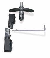
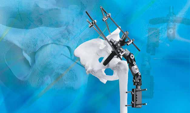
3 Introduction The DFS Hip Distractor provides unloading of the hip joint while permitting free range of motion. This treatment has very specific applications and should be performed only in cases where off loading the joint is expected to provide a distinct advantage in patient treatment. Hinged distraction arthroplasty is a treatment modality commonly associated with Avascular Necrosis of the femoral head, Legg-Calves-Perthes Disease, chondrolysis, protection of the joint after femoral head fracture, and after labral reconstruction. Dynamic Joint Distraction has proven effective for several joints such as the elbow and ankle for secondary arthritis. Off loading the joint while allowing cartilage nutrition and healing of the subchondral bone may restore a functioning joint surface in processes such as Osteonecrosis and Chondrolysis. After femoral head fracture or labral reconstruction joint distraction and movement will allow healing while preventing stiffness. The DFS Hip Distractor is comprised of three basic components: 1) Hip Distractor clamp (PN-01220) 2) Construx Fixator (PN-01801) 3) Bone screw clamps for hip clamp (PN-06240) 4) Accessory components to build outriggers are also available. With the exception of the Hip Distractor clamp, these components hold similarities to other Biomet Trauma components. This clamp is unique due to its hemi-arc shape, which offers variable bone screw placement, and most importantly due to its ability to distract up to 5cm. The key attribute of this system is in its ability to distract proximally and not distally. When distracting from the proximal end of the device the hinge maintains its orientation to the femoral head, which serves as the center of rotation of the joint. If one were to distract from the distal end of the fixator, the center of rotation would be fixated on the hip socket and not the femur. Therefore the fixator ultimately would articulate off center. 1

4 Hip Distractor Associated Components And Instrumentation Part # Description Construx Fixator Hip Distractor Clamp Hip Distraction CD Wrench* mm Allen Wrench* mm Wire Guide* mm Bone Clamp* Soft Tissue Clamp / Template* Angulating Screw Clamp Trocar T-Wrench for Bone Screws Soft Tissue Guide 100mm mm Drill Guide mm Drill Bit 240mm mm Drill Guide mm Drill Bit 200mm *Included with
 Part # Description 14605 Vision")

5 Part # Description mm Supplemental Carbon Rod (x2) Supplemental Bone Screw Clamp (x4) Part # Description Vision MRI Safe Pin-To-Bar Clamp (x2) or SL Rapid 6.0 mm Screw Clamp Part # Description mm Carbon Rod or mm Carbon Rod 3


6 Radiographs The patient should be placed supine on the radiolucent table, with a small bolster under the affected hip. The fluoroscope should be positioned so that an appropriate A/P and lateral images can be taken with minimal effort (NOTE: Expect to use several sterile covers for the fluoroscope head as it will be used for both lateral and A/P projections). The center of the femoral head is judged to be the center of rotation for the hip. Under fluoroscopic guidance, the center of the femoral head is found and marked. If the femoral head is collapsed and does not appear as a true sphere, the center should be assumed at the center of the femoral head as though the head was complete and intact. A line from the top of the greater trochanter to the center of the femoral head in neutral hip position is marked as well using a 2.0 mm k-wire. This newly marked point is the center of rotation for the hip, our hinge will be located at this point. 4

7 Fixator Orientation The center of the pivot body is cannulated (2.0mm), depicting the center of rotation for the fixator. The pivot body assembly should now be placed over the k-wire used to identify the center of rotation for the joint. The proximal bone screws can now be placed. The fixator should be pre-spaced away from the patient to contend with any swelling or pistoning of the soft tissue that may occur during treatment. Before drilling your first proximal bone screw, the degree (if any) of abduction should be determined. If 10 of abduction is preferred, the bone screw must be abducted before it is placed (i.e. superolateral to inferomedial). The first screw should be templated through the proximal clamp. To avoid soft tissue damage, templates are provided. The templates look very similar to the bone screw holding clamps but are designed to hold soft tissue guides, whereas the bone screw clamps cannot. If the templates are used, they should be exchanged for the actual clamps only after all proximal clamp bone screws are placed. 5
 to center the bit within the soft tissue guide, a 4.8 mm bit (PN-03010) is used to drill into the pelvic wall.")


8 Initial Screw Placement With the templates and soft tissue guides (PN-03085) in place, the first screw is ready to be placed. Using a drill guide (PN ) to center the bit within the soft tissue guide, a 4.8 mm bit (PN-03010) is used to drill into the pelvic wall. The use of fluoroscopy is imperative to assure that over-penetration in not achieved (fluoroscopic Judet views can be utilized to confirm placement). Drill stops are recommended to prevent over-penetration. The first screw placed should be the most anterior screw as bone stock and bone screw placement is more limited in this area. Placement of the proximal bone screws is in the superoacetabular region, and these are placed approximately 2 cm above the joint. The first bone screw should be placed in the desired predetermined abduction or adduction position. After the hole is drilled, the drill guide is removed. The appropriate-length screw is selected and inserted into the template and soft tissue guide. Using a bone screw T-Wrench (PN-03125), the bone screw is inserted two to three threads past the far cortex by turning it clockwise. Judet views can be utilized to prevent over-penetration. NOTE: Care should be taken to avoid over-penetration as the bone screws are tapered and will lose purchase if they are backed out. 6

9 Remaining Proximal Screw Insertion NOTE: Make sure to select bone screws long enough to support the additional outriggers that will be placed on the screws as they protrude from the back of the clamp. It is also recommended to use Hydroxyapatite Coated bone screws for these procedures. The second (and third, if desired) proximal bone screw is templated and placed accordingly, making sure not to force placement through the template and move the hinge (this is reflected by bending the guide pin). In most cases, there will be two bone screws applied anterior to the distraction post and one placed posterior to the post. The remaining bone screws are placed in the same fashion as the first; template, drill, and insert the appropriate bone screw. If the ilium is small and cannot tolerate three bone screws at the same level than one bone screw can be placed 1 cm proximal. A 2.0 mm wire can be utilized to determine if it is safe to place posterior bone screws (i.e. not violating the sciatic notch). 7


10 Distal Assembly Once the proximal bone screws are placed, the distal portion of the fixator, comprised of a Construx Fixator (PN-01801) can be assembled. First remove the bolt connecting the Male knuckle of the fixator to the clamp assembly. This is depicted in the pictures below. Loosen all the locking bolts and setscrews so the fixator can be manipulated freely. If the fixator measures long on the patient, simply remove the necessary number of knuckles until the desired length is achieved. Using the bolt previously used to separate the Construx Fixator from its unused half, attach the Construx Fixator to the rest of the hip distractor assembly on the patient. Telescope the distal clamp on the Construx Fixator approximately 2 cm and lock it in position by tightening the set-screw on the inferior side of the clamp body. The knuckles of the fixator should be in a straight line. 8


11 Distal Bone Screw Insertion Using the fixator as a template, insert two to three soft tissue guides (PN-03085) and place the distal clamp laterally on the femur and parallel to the bone. The femur should be positioned while applying the distal bone screws in the same abduction as the perpendicular proximal bone screws in the ilium. Wire guides can be utilized as demonstrated below to template placement of the bone screws prior to initial drilling. 9

12 Distal Bone Screw Insertion (Continued) Using the 4.8 mm drill guide (PN-03060) and the corresponding drill bit, pre-drilling for the first bone screw can now take place. Bi-cortical penetration is required for this procedure. It is important to pre-drill one hole at a time and then insert the screw. (Do not attempt to pre-drill all three holes and then insert the bone screws.) The most distal bone screw is inserted first, followed by the most proximal, finishing with the third, centrally located bone screw. Once the remaining screws are placed in the recommended sequence, the soft tissue guides are removed. The clamps and fixator knuckles should now be definitively tightened from top to bottom. 10

 A single bone screw placed anterior-inferior to")
13 Necessary Outriggers Supplemental bone screw fixation is strongly recommended due to the immense torsional forces being exerted on the bone screw sites. This additional support can be achieved by one of two approaches: 1) The addition of two convergent bone screws placed between the tables of the ilium, or 2) A single bone screw placed anterior-inferior to postero-superior at the level of the anterior inferior iliac spine. 11


14 Necessary Outriggers (Continued) Option 1 In pre-drilling the iliac wing screws, the hole does not need to be drilled deeply. A soft tissue guide, 4.8 mm drill guide, and 4.8 mm drill bit should be used as this size corresponds to the 5.0/6.0 mm bone screws. Both of these bone screws may be placed freehand. The pelvic wall of the iliac wing is very dense, whereas the bone stock within the wall is comprised of cancellous bone. This offers a unique advantage in placing bone screws, as the pelvic wall will guide the bone screws. Once the near cortex is drilled, the screw is inserted and should find its own path. Once the first hole is drilled, the bit and guide are removed and the appropriate bone screw is inserted using a bone screw T-Wrench. The next step is to connect the screws in the iliac wing to the proximal portion of the fixator. For option one, it is easiest to use two 250 mm supplemental bars (PN-13105), and four supplemental clamps (PN-01525) to attach the bars to the shanks of the screws coming out of the proximal clamp and the screw shanks protruding from the iliac wing. A small 150 mm supplemental bar (PN-01515) with two supplemental clamps may also be used to lag the two 300 mm rods together by the wing and add further stability to this Delta-style construct. 12


15 Option 2 Using a soft tissue guide, 4.8 mm drill guide, and 4.8 mm drill bit, the anterior screw is placed. Positioning of this screw should be verified fluoroscopically. This screw should be placed as deep as the surgeon feels is sufficient to provide adequate fixation. Bi-cortical penetration is NOT recommended. Once the bone screw is inserted, the outrigger can be attached. By linking a 150 mm rod (with use of clamps) to the proximal portion of the fixator and to the new screw site, supplemental fixation is achieved. 13
16 Flexion Once the frame is applied, the patient s leg should be flexed and extended under fluoroscopy. If the hinge has been aligned properly, articulation should occur freely. If the limb does not articulate freely, the orientation of the fixator is most likely off axis. There is a trouble-shooting segment at the end of this technique, which may prove helpful. Distraction Once the outriggers are secured in place, the distraction can be performed. Some surgeons may wish to distract their patients gradually; others prefer to perform it intra-operatively and all at once. Regardless, the steps are the same. First loosen the distraction locking set-screw. This is the silver setscrew located on the front of the hip distractor clamp below the distraction nut. Turning the set-screw counterclockwise will loosen it, and clockwise will lock it. Once the set-screw has been loosened, the distraction nut can be turned. Using the distractor wrench (PN-01227), turn the distraction nut counterclockwise (viewing the adjustment nut from top down) until the desired amount of distraction is achieved. When not adjusting the distraction nut always lock it using the setscrew. Distraction may either be done acutely or slowly, to achieve restoration of Shenton s line, distraction typically is between 5.0 mm and 8.0mm. The proximal distractor should be utilized, thereby moving the hinge and the femoral head together and achieving a smooth range of motion, even after distraction. After this is achieved the distractor is locked. 14
17 Post-Operative Care Patient may benefit from postoperative knee CPM (0-30 ) which brings the hip to nearly 70 of flexion An epidural may be utilized with the CPM for initial pain management Antibiotic, bone screw care and showering as per physician protocol Ordinarily patient may weight-bear as tolerated, but this is case-dependant Duration of frame-wear is case-dependent averaging three to five months for avascular necrosis Problems/Solutions Problem Hinge placement is too proximal (or distal), noted prior to applying the femoral bone screws. Solution Simply lengthen or shorten the proximal distractor. In the rare event that the hinge is too distal and there is no more room to shorten the distractor, the problem can be solved by doing a distraction from the femoral clamp after the femoral bone screws have been applied. This will effectively bring the femoral head down to the level of the hinge. Problem After the frame is on, the hinge is too proximal. Solution This is solved by distracting through the proximal distractor and then compressing distally at the femur. This will bring the hinge distally. Once the hinge is aligned, distraction from the proximal device may continue. Problem The hip is not able to be brought into the neutral position prior to surgery. Solution Soft tissue release should be performed prior to pin placement as needed. Problem Post-operatively the patient has a tendency to hold the hip in flexion and may be developing a contracture. Solution Lock frame in extension at night. 15
18 Suggested Screw Site Care At the conclusion of fixator application and fracture reduction, wounds are dressed in routine sterile fashion. Care should be taken to insure all fixator fittings are securely tightened. Dry sterile gauze is wrapped around the shanks of the bone screws to prevent pistoning of the soft tissues on the bone screws. Once wounds have healed and sutures are removed, routine postoperative screw site care is recommended. Screw sites should be monitored during subsequent clinic visits. All fixator fittings should be evaluated for tightness during subsequent clinic visits. 16
19 Further Information This brochure describes the surgical technique used by David S. Feldman, M.D., Chief, Pediatric Orthopedic Surgery NYU & Hospital for Joint Diseases. Biomet Trauma, as the manufacturer of this device, does not practice medicine, a nd does not recommend this product or any specific surgical technique for use on any individual patient. The surgeon who performs any implant procedure is responsible for determining the appropriate product(s) and utilizing the appropriate technique(s) for said implantation in each individual patient. For further information, please contact the Customer Service Department at: Biomet Trauma 56 East Bell Drive P.O. Box 587 Warsaw, Indiana x
20 All trademarks herein are the property of Biomet, Inc. or its subsidiaries unless otherwise indicated. This material is intended for the sole use and benefit of the Biomet sales force and health care professionals. It is not to be redistributed, duplicated or disclosed without the express written consent of Biomet. For product information, including indications, contraindications, warnings, precautions and potential adverse effects, see the package insert and Biomet s website. Responsible Manufacturer Biomet, Inc. P.O. Box E. Bell Drive Warsaw, Indiana USA Rx only Biomet Orthopedics Form No. BMET REV
DFS STANDARD FIXATOR DFS ANKLE CLAMP DFS T-CLAMP
 DFS STANDAD FIXATO DFS ANKLE CLAMP DFS T-CLAMP SUGICAL TECHNIQUE Dr. James V. Nepola Professor of Orthopaedics University of Iowa Hospitals and Clinics Iowa City, Iowa Patent No. 5,662,650 C ontents DynaFix
Access Pelvic Fixator
 Access Pelvic Fixator Attila Poka, MD Director, Orthopedic Trauma Service Grant Medical Center Columbus, OH Patents Pending CONTENTS 1 Introduction...Page 2 Equipment Required...Page 3 Design Rationale...Page
Biomet Carbon Rail Deformity System. Surgical Technique
 Biomet Carbon Rail Deformity System Surgical Technique Contents Introduction... Page 1 System Components... Page 2 Indications, Contraindications, and Deformity Planning... Page 4 Deformity Planning-Identifying...
Biomet Large Cannulated Screw System
 Biomet Large Cannulated Screw System s u r g i c a l t e c h n i q u e A Complete System for Simplified Fracture Fixation 6.5mm & 7.3mm The Titanium, Self-drilling, Self-tapping Large Cannulated Screw
Knee Surgical Technique
 Knee Surgical Technique COMPASS Universal Hinge by Jimmy Tucker, M.D. Orthopaedic Surgeon Director, Arkansas Sports Medicine, P.A. Little Rock, Arkansas Table of contents Design features 3 Indications
Biomet Multi-Axial Correction (MAC) System Correction Atlas
 System Correction Atlas") Biomet Multi-Axial Correction (MAC) System Correction Atlas Demonstrated with the XS MAC on a Left Tibia (CORA Centric Approach) Introduction... Page 1 Indications/ Contraindictions... Page 1 MAC Module
Biomet Multi-Axial Correction (MAC) System Correction Atlas Demonstrated with the XS MAC on a Left Tibia (CORA Centric Approach) Introduction... Page 1 Indications/ Contraindictions... Page 1 MAC Module
FastFrame External Fixation System. Damage Control Surgical Technique
 FastFrame External Fixation System Damage Control Surgical Technique 1 FastFrame External Fixation System Damage Control Surgical Technique Table of Contents Introduction... 2 Indications and Contradictions...
Biomet. Vision Pin-To-Bar System. Surgical Technique. Calcaneal Reduction Frame
 Biomet Vision Pin-To-Bar System Surgical Technique Calcaneal Reduction Frame One Surgeon. One Patient. Over 1 million times per year, Biomet helps one surgeon provide personalized care to one patient.
Case Study: David. Conditions Treated Femoral Neck Fracture with Avascular Necrosis of the Hip. Age Range During Treatment 16 Years
 Case Study: David Conditions Treated Femoral Neck Fracture with Avascular Necrosis of the Hip Age Range During Treatment 16 Years David S. Feldman, MD Chief of Pediatric Orthopedic Surgery Professor of
Taperloc Complete Hip System. Surgical Technique
 Taperloc Complete Hip System Surgical Technique One Surgeon. One Patient. Over 1 million times per year, Biomet helps one surgeon provide personalized care to one patient. The science and art of medical
Signature Personalized Patient Care
 Surgical Technique Acetabular Guide System Contents One Surgeon. One Patient. Over 1 million times per year, Biomet helps one surgeon provide personalized care to one patient. The science and art of medical
OSS Modular Arthrodesis System. Assembly Guide
 OSS Modular Arthrodesis System Assembly Guide One Surgeon. One Patient. Over 1 million times per year, Biomet helps one surgeon provide personalized care to one patient. The science and art of medical
QUICK REFERENCE GUIDE. Arthrodiatasis. Articulated Joint Distraction
 4 Arthrodiatasis Articulated Joint Distraction ARTHRODIATASIS OF THE HIP To prepare the assembly, remove the female component and replace it with the ProCallus articulated body for the hip. Remove cam
Zimmer ITST Intertrochanteric/ Subtrochanteric Fixation System. Abbreviated Surgical Technique
 Zimmer ITST Intertrochanteric/ Subtrochanteric Fixation System Abbreviated Surgical Technique ITST System Abbreviated Surgical Technique Indications The ITST Intramedullary Nail is indicated for use in
Orthopedic Bone Nail System - Distal Femoral Nail Surgical Technique Manual
 Orthopedic Bone Nail System - Distal Femoral Nail Surgical Technique Manual Note: The surgical procedures should be performed under the guidance of qualified skilled orthopedic surgeons, and this surgical
QUICK REFERENCE GUIDE. The XCaliber Meta-Diaphyseal Fixator
 17 The XCaliber Meta-Diaphyseal Fixator GENERAL POINTS The XCaliber Fixator is made of radiolucent material for unobstructed X-ray visualization. The metallic bolts and the cam and bush of each ball-joint,
Technique Guide. LCP Proximal Femoral Hook Plate 4.5/5.0. Part of the LCP Periarticular Plating System.
 Technique Guide LCP Proximal Femoral Hook Plate 4.5/5.0. Part of the LCP Periarticular Plating System. Table of Contents Introduction Features and Benefits 2 AO ASIF Principles 4 Indications 5 Surgical
Biomet Vision Pin-To-Bar Fixation System. Surgical Technique
 Biomet Vision Pin-To-Bar Fixation System Surgical Technique Contents Introduction... Page 1 Indications and Contraindications... Page 2 Basic Principles And Biomechanical Concepts...Page 3 Instruments...
Pre-Operative Planning. Positioning of the Patient
 Surgical Technique Pre-Operative Planning Decide upon the size and angle of the barrel plate to be used from measuring the x-rays. To maximise the sliding action when using shorter lag screws, the Short
Flexible Fragment Fixation. Surgical Technique
 Flexible Fragment Fixation Surgical Technique 2 F 3 Flexible Fragment Fixation The F 3 Fragment Plating System offers low profile, yet strong fixation in a locked plating construct that can be contoured
Surgical Technique. CONQUEST FN Femoral Neck Fracture System
 Surgical Technique CONQUEST FN Femoral Neck Fracture System Table of Contents Introduction... 3 Indications... 3 Product Overview... 4 Surgical Technique... 5 Patient Positioning... 5 Reduce the Fracture...
Zimmer MIS Periarticular 3.5mm Proximal Tibial Locking Plate
 Zimmer MIS Periarticular 3.5mm Proximal Tibial Locking Plate Surgical Technique The Science of the Landscape Zimmer MIS Periarticular 3.5mm Proximal Tibial Locking Plate Surgical Technique 1 Zimmer MIS
External Fixator Brochure
 External Fixator Brochure Response Ortho is a global orthopaedic trauma solutions manufacturer offering premium products created under its founding principles of innovation, excellence by design and functional
OptiLock Periarticular Plating System For Distal Tibial Fractures. Surgical Technique
 OptiLock Periarticular Plating System For Distal Tibial Fractures Surgical Technique Contents Introduction... Page 1 Indications & Contraindications... Page 6 System Features... Page 7 Surgical Technique...
The NBX Non-Bridging External Fixator A Non-Bridging External Fixator/Locking Plate capturing a series of.062mm K-wires and 3mm half-pins that are
 The NBX Non-Bridging External Fixator A Non-Bridging External Fixator/Locking Plate capturing a series of.062mm K-wires and 3mm half-pins that are inserted in a multiplanar and multi-directional fashion
Technique Guide. The Distraction Osteogenesis Ring System. Nonarticular tibia frame.
 Technique Guide The Distraction Osteogenesis Ring System. Nonarticular tibia frame. Table of Contents Introduction The Distraction Osteogenesis Ring System 2 AO Principles 4 Indications 5 Surgical Technique
ACETABULAR CUP SURGICAL TECHNIQUE
 ACETABULAR CUP SURGICAL TECHNIQUE ACETABULAR CUP DEVICE INDICATIONS FOR USE The ICONACY I-Hip total hip replacement is indicated for the following conditions: 1. A severely painful and/or disabled hip
System. Humeral Nail. Surgical Technique
 System Humeral Nail Surgical Technique Contents IMPLANT FEATURES 2 1. INDICATIONS 3 2. PRE-OPERATIVE PLANNING 3 3. PATIENT POSITIONING & FRACTURE REDUCTION 3 4. INCISION 4 5. ENTRY POINT 4-6 6. PROXIMAL
ToggleLoc Inline Device
 ToggleLoc Inline Device with ZipLoop Technology and TunneLoc Tibial Fixation for ACL Reconstruction Surgical Technique Surgical Protocol by Jeffrey M. Conrad, M.D. SPORTS MEDICINE One Surgeon. One Patient.
Arcos Interlocking Distal Stem. Surgical Technique Addendum to the Arcos Modular Femoral Revision System
 Arcos Interlocking Distal Stem Surgical Technique Addendum to the Arcos Modular Femoral Revision System One Surgeon. One Patient. Over 1 million times per year, Biomet helps one surgeon provide personalized
QUICK REFERENCE GUIDE. The PreFix Fixator (92000 Series) ALWAYS INNOVATING
 ALWAYS INNOVATING") 21 The PreFix Fixator (92000 Series) ALWAYS INNOVATING INTRODUCTION The PreFix fixator is designed to provide temporary external fixation. This may be needed when local facilities or the condition of the
21 The PreFix Fixator (92000 Series) ALWAYS INNOVATING INTRODUCTION The PreFix fixator is designed to provide temporary external fixation. This may be needed when local facilities or the condition of the
OSS Orthopedic Salvage System Compress Device. Surgical Technique
 OSS Orthopedic Salvage System Compress Device Surgical Technique Table of Contents Quick Reference Guide... 2 Device Description... 3 Resection... 4 No Face Adapter Provisional Construct... 4 Canal Preparation...
StageOne. Shoulder Cement Spacer Molds. Surgical Technique
 StageOne Shoulder Cement Spacer Molds Surgical Technique One Surgeon. One Patient. Over 1 million times per year, Biomet helps one surgeon provide personalized care to one patient. The science and art
LCP Medial Distal Tibia Plate, without Tab. The Low Profile Anatomic Fixation System with Angular Stability and Optimal Screw Orientation.
 LCP Medial Distal Tibia Plate, without Tab. The Low Profile Anatomic Fixation System with Angular Stability and Optimal Screw Orientation. Technique Guide LCP Small Fragment System Table of Contents Introduction
The AperFix II System
 The AperFix II System A Complete Anatomic Solution Transtibial Surgical Technique 2 AperFix II System Transtibial Surgical Technique Figure 1 A Complete Anatomic Solution The Cayenne Medical AperFix and
Resurfacing Distal Femur. Orthopaedic Salvage System
 Resurfacing Distal Femur Orthopaedic Salvage System Primary Arthroplasty OSS 3cm Resurfacing Distal Femur Distal Femoral Resection Drill and ream the distal femur in the following sequence: (Figure 1)
Conventus CAGE PH Surgical Techniques
 Conventus CAGE PH Surgical Techniques Conventus Orthopaedics The Conventus CAGE PH (PH Cage) is a permanent implant comprised of an expandable scaffold, made from nitinol and titanium, which is deployed
3. PATIENT POSITIONING & FRACTURE REDUCTION 3 8. DISTAL GUIDED LOCKING FOR PROXIMAL NAIL PROXIMAL LOCKING FOR LONG NAIL 13
 Contents IMPLANT FEATURES 2 1. INDICATIONS 3 2. PRE-OPERATIVE PLANNING 3 3. PATIENT POSITIONING & FRACTURE REDUCTION 3 4. INCISION 4 5. ENTRY POINT 4-6 6. PROXIMAL NAIL INSERTION 6-7 7. PROXIMAL LOCKING
Femur. Monoaxial Locking Plate System. Operative Technique. Distal Lateral Femur Universal Holes Targeting Instrumentation.
 Femur AxSOS 3 Titanium Monoaxial Locking Plate System Femur Fractures Operative Technique Distal Lateral Femur Universal Holes Targeting Instrumentation This publication sets forth detailed recommended
Knee spanning solutions
 Knee spanning solutions System features Indications Intended to be used on adults or pediatric patients as required for fracture fixation (open or closed); post-traumatic joint contracture which has resulted
PediLoc 3.5mm and 4.5mm Bowed Femur Plate Surgical Technique
 PediLoc 3.5mm and 4.5mm Bowed Femur Plate Surgical Technique 2957 Bow Broch_REV_B.indd 1 2/10/11 12:47 PM Surgical Technique Bowed Femur Plate The technique description herein is made available to the
OPERATIVE TECHNIQUE. Knee Hinge (LRS Advanced System)
") OPERTIVE TECHNIQUE Knee Hinge (LRS dvanced System) 1 1 2 4 6 INTRODUCTION INDICTIONS FETURES ND BENEFITS EQUIPMENT REQUIRED KNEE HINGE SSEMBLY 8 17 TRUM KNEE DISLOCTION Orthofix wishes to thank the following
OPERTIVE TECHNIQUE Knee Hinge (LRS dvanced System) 1 1 2 4 6 INTRODUCTION INDICTIONS FETURES ND BENEFITS EQUIPMENT REQUIRED KNEE HINGE SSEMBLY 8 17 TRUM KNEE DISLOCTION Orthofix wishes to thank the following
Arcos Modular Femoral Revision System. Broach and Calcar Proximal Bodies Surgical Technique
 Arcos Modular Femoral Revision System Broach and Calcar Proximal Bodies Surgical Technique Table of Contents Pre-operative Planning...2 Patient Positioning and Surgical Approach...2 Removal of a Cemented
Zimmer Small Fragment Universal Locking System. Surgical Technique
 Zimmer Small Fragment Universal Locking System Surgical Technique Zimmer Small Fragment Universal Locking System 1 Zimmer Small Fragment Universal Locking System Surgical Technique Table of Contents Introduction
DARCO. Bow 2 Plate SURGIC AL TECHNIQUE
 DARCO Bow 2 Plate SURGIC AL TECHNIQUE Contents 2 Preface 3 Chapter 1 4 Chapter 2 5 6 7 8 9 Appendix 10 10 11 Intended Use Indications/Contraindications Design Rationale Preoperative Planning Surgical Technique
RibFix Blu. Thoracic Fixation System
 RibFix Blu RibFix Blu Thoracic Fixation System The New Era of Rib Fixation Begins Now Designed by Trauma Surgeons for Trauma Surgeons Your work matters and so do your patients. We are continually engineering
Technique Guide. 3.5 mm LCP Low Bend Medial Distal Tibia Plate Aiming Instruments. Part of the 3.5 mm LCP Percutaneous Instrument System.
 Technique Guide 3.5 mm LCP Low Bend Medial Distal Tibia Plate Aiming Instruments. Part of the 3.5 mm LCP Percutaneous Instrument System. Table of Contents Introduction 3.5 mm LCP Low Bend Medial Distal
Case Report. Antegrade Femur Lengthening with the PRECICE Limb Lengthening Technology
 Case Report Antegrade Femur Lengthening with the PRECICE Limb Lengthening Technology S. Robert Rozbruch, MD Hospital for Special Surgery New York, NY, USA ABSTRACT This is a case illustrating a 4.5 cm
Zimmer MIS Periarticular Distal Femoral Locking Plate
 For Clinical Evaluations Zimmer MIS Periarticular Distal Femoral Locking Plate Surgical Technique The Science of the Landscape Zimmer MIS Periarticular Distal Femoral Locking Plate Surgical Technique
DVR Crosslock Distal Radius Plating System. Product Brochure
 DVR Crosslock Distal Radius Plating System Product Brochure One Surgeon. One Patient. Over 1 million times per year, Biomet helps one surgeon provide personalized care to one patient. The science and art
PediLoc Extension Osteotomy Plate (PLEO)
") PediLoc Extension Osteotomy Plate (PLEO) Left PLEO Plates Sizes: 6, 8 and 10 hole plates Right PLEO Plates Sizes: 6, 8 and 10 hole plates PediLoc Extension Osteotomy Plate The technique description herein
PediLoc Extension Osteotomy Plate (PLEO) Left PLEO Plates Sizes: 6, 8 and 10 hole plates Right PLEO Plates Sizes: 6, 8 and 10 hole plates PediLoc Extension Osteotomy Plate The technique description herein
MIS Cemented Tibial Component
 MIS Cemented Tibial Component NexGen Complete Knee Solution Surgical Technique Table of Contents Surgical Exposure... 2 Finish the Tibia... 2 Position Based on Anatomic Landmarks... 3 Lateral Posterior
Alignment Rod. For intraoperatively confirming correction of the mechanical leg axis.
 Alignment Rod. For intraoperatively confirming correction of the mechanical leg axis. Easy to use Accuracy of surgery Reduces X-ray exposure Table of Contents Introduction Alignment Rod 2 Handling Technique
Technique Guide. Adjustable Distal Radius Fixator. Part of the Synthes External Fixation Systems.
 Technique Guide Adjustable Distal Radius Fixator. Part of the Synthes External Fixation Systems. Table of Contents Introduction Adjustable Distal Radius Fixator 2 Indications 3 Surgical Technique Configure
LCP Medial Proximal Tibial Plate 3.5. Part of the Synthes small fragment Locking Compression Plate (LCP) system.
 system.") LCP Medial Proximal Tibial Plate 3.5. Part of the Synthes small fragment Locking Compression Plate (LCP) system. Technique Guide This publication is not intended for distribution in the USA. Instruments
LCP Medial Proximal Tibial Plate 3.5. Part of the Synthes small fragment Locking Compression Plate (LCP) system. Technique Guide This publication is not intended for distribution in the USA. Instruments
MICRONAIL. Intramedullary Distal Radius System SURGICAL TECHNIQUE
 MICRONAIL II Intramedullary Distal Radius System SURGICAL TECHNIQUE Contents Introduction 3 4 Chapter 1 5 Chapter 2 6 Appendix A 18 Appendix B 19 Surgeon Design Team Introduction Product Information Surgical
Arcos Modular Femoral Revision System
 Arcos Modular Femoral Revision System Arcos System Simplify the Complex The Arcos Modular Femoral Revision System meets the demands of complex hip revision surgery by offering surgeons and OR staff the
Large Distractor Femur
 Fracture Reduction and Provisional Stabilization Large Distractor Femur Surgical Technique Table of Contents Introduction Standard Femoral Distraction 2 Large Distractor System 4 Surgical Technique Prepare
PediNail Pediatric Femoral Nail
 PediNail Pediatric Femoral Nail Surgical Technique Table of Contents Indications...3 Patient Positioning...3 Approach...4 Reaming...5 Nail Placement...6 Proximal Interlocking...7 Distal Interlocking...8
Workshop Outline. Pre-operative planning
 Workshop Objective To build and apply the True/Lok TM circular external fixator frame for correction of the Charcot forefoot deformity (Lisfranc fracture dislocation) Workshop Outline Pre-operative planning
U2 PSA. Revision Knee. Surgical Protocol
 U2 PSA TM Revision Knee Surgical Protocol Table of Contents 1 Component Removal... 1 2 Tibial Preparation... 1 2.1 Tibial Canal Preparation... 1 2.2 Proximal Tibial Resection... 2 2.3 Non Offset Tibial
Surgical Technique. Anterolateral and Medial Distal Tibia Locking Plates
 Surgical Technique Anterolateral and Medial Distal Tibia Locking Plates PERI-LOC Periarticular Locked Plating System Anterolateral and Medial Distal Tibia Locking Plates Surgical Technique Contents Product
Technique Guide. 3.5 mm LCP Proximal Tibia Plate. Part of the Synthes Small Fragment LCP System.
 Technique Guide 3.5 mm LCP Proximal Tibia Plate. Part of the Synthes Small Fragment LCP System. Table of Contents AO ASIF Principles of Internal Fixation 4 Indications/Contraindications 5 Surgical Technique
ToggleLoc. Fixation Device. Surgical Technique. Femoral Fixation for ACL Reconstruction SPORTS MEDICINE. Surgical Protocol by Mark Gittins, D.O.
 ToggleLoc Fixation Device Femoral Fixation for ACL Reconstruction Surgical Technique Surgical Protocol by Mark Gittins, D.O. SPORTS MEDICINE One Surgeon. One Patient. Over 1 million times per year, Biomet
Comprehensive Reverse Shoulder System
 Comprehensive Reverse Shoulder System Comprehensive Reverse Shoulder System Simple. Versatile. The Comprehensive Reverse Shoulder System is the next generation reverse shoulder prosthesis, offering unmatched
Anterior Angular Hinge Fixator
 At Biomet, engineering excellence is our heritage and our passion. For over 25 years, through various divisions worldwide, we have applied the most advanced engineering and manufacturing technology to
RECOVERY. P r o t r u s i o
 RECOVERY P r o t r u s i o TM C a g e RECOVERY P r o t r u s i o TM C a g e Design Features Revision acetabular surgery is a major challenge facing today s total joint revision surgeon. Failed endo/bi-polars,
Technique Guide. 3.5 mm LCP Low Bend Medial Distal Tibia Plates. Part of the Synthes locking compression plate (LCP) system.
 system.") Technique Guide 3.5 mm LCP Low Bend Medial Distal Tibia Plates. Part of the Synthes locking compression plate (LCP) system. Table of Contents Introduction 3.5 mm LCP Low Bend Medial Distal Tibia Plates
Technique Guide 3.5 mm LCP Low Bend Medial Distal Tibia Plates. Part of the Synthes locking compression plate (LCP) system. Table of Contents Introduction 3.5 mm LCP Low Bend Medial Distal Tibia Plates
comprehensive Design Rationale shoulder system Knees Hips Extremities Cement and Accessories PMI TEchnology
 comprehensive shoulder system Design Rationale Knees Hips Extremities Cement and Accessories PMI TEchnology . INTRODUCTION The Comprehensive Shoulder System is an evolutionary design based on the successful
Medical Devices DYNAMIC MULTIAXIAL FIXATOR
 Medical Devices DDDAF DYNAMIC MULTIAXIAL FIXATOR DAF DYNAMIC MULTIAXIAL FIXATOR It is a single plan external fixation tool. The ball-joint structure connects the clamp to the fixator body as an articular
Cannulated Pediatric Osteotomy System (CAPOS). A single system of osteotomy blade plates and cannulated instrumentation.
. A single system of osteotomy blade plates and cannulated instrumentation.") Cannulated Pediatric Osteotomy System (CAPOS). A single system of osteotomy blade plates and cannulated instrumentation. Technique Guide This publication is not intended for distribution in the USA. Instruments
Cannulated Pediatric Osteotomy System (CAPOS). A single system of osteotomy blade plates and cannulated instrumentation. Technique Guide This publication is not intended for distribution in the USA. Instruments
Polyax Distal Femoral Locked Plating System. Surgical Technique
 Polyax Distal Femoral Locked Plating System Surgical Technique Polyax Distal Femoral Locked Plating System Contents Introduction and Indications... 3 System Features... 4 Surgical Technique... 5 Patient
QUICK REFERENCE GUIDE. The Orthofix Femoral Nailing System. By Prof. Dr. D. Pennig
 QUICK REFERENCE GUIDE The Orthofix Femoral Nailing System By Prof. Dr. D. Pennig Whenever possible, femoral fractures should be stabilized within the first 24 hours following injury, provided the patient
EBI FIX DYNAFIX SYSTEM VISION EXTERNAL FIXATION SURGICAL TECHNIQUE. Patent 6,277,119
 EBI DYNAFIX FIX SYSTEM DYNAFIX VISION EXTERNAL FIXATION SYSTEM SURGICAL TECHNIQUE Patent 6,277,119 1 CONTENTS Basic Principles and Biomechanical Concepts...Page 2 Introduction...Page 2 Component Review...
Cannulated Pediatric Osteotomy System (CAPOS)
") A Single System of Osteotomy Blade Plates and Cannulated Instrumentation Cannulated Pediatric Osteotomy System (CAPOS) Surgical Technique Table of Contents Introduction Cannulated Pediatric Osteotomy System
A Single System of Osteotomy Blade Plates and Cannulated Instrumentation Cannulated Pediatric Osteotomy System (CAPOS) Surgical Technique Table of Contents Introduction Cannulated Pediatric Osteotomy System
Greater Component Accuracy...
 Greater Component Accuracy... StageOne cement spacer molds are designed to provide the surgeon with choices never before offered in two-stage revision knee surgery for an infected total joint. StageOne
LCP Anterolateral Distal Tibia Plate 3.5. The low profile anatomic fixation system with optimal plate placement and angular stability.
 LCP Anterolateral Distal Tibia Plate 3.5. The low profile anatomic fixation system with optimal plate placement and angular stability. Technique Guide LCP Small Fragment System Table of Contents Introduction
100 Interpace Parkway Parsippany, NJ
 100 Interpace Parkway Parsippany, NJ 07054 www.biometspine.com 800-526-2579 All trademarks are the property of Biomet, Inc. or one of its subsidiaries, unless otherwise indicated. Rx Only. 2009 EBI, LLC.
Tibial Fixation. with TunneLoc Device. Surgical Technique by Mark J. Albritton, M.D. and Sherwin Ho, M.D.
 Tibial Fixation with TunneLoc Device Surgical Technique by Mark J. Albritton, M.D. and Sherwin Ho, M.D. Table of Contents Surgical Technique... 4 Ordering Information... 11 Indications For Use... 12 Contraindications...
3.5 mm LCP Low Bend Medial Distal Tibia Plate Aiming Instruments
 Part of the 3.5 mm LCP 3.5 mm LCP Low Bend Medial Distal Tibia Plate Aiming Instruments Surgical Technique TABLE OF CONTENTS INTRODUCTION 3.5 mm LCP Low Bend Medial Distal Tibia Plate 2 Aiming Instruments
OPERATING MANUAL AND TECHNIQUE GUIDE FOR TITANIUM FEMORAL AND TIBIAL NAILING SYSTEMS
 OPERATING MANUAL AND TECHNIQUE GUIDE FOR TITANIUM FEMORAL AND TIBIAL NAILING SYSTEMS ORTHO-MEDICAL GMBH TITANIUM FEMORAL NAIL OPERATIVE TECHNIQUE Introduction: Why a new type of femoral nail? The latest
LCP Anterolateral Distal Tibia Plate 3.5. The low profile anatomic fixation system with optimal plate placement and angular stability.
 LCP Anterolateral Distal Tibia Plate 3.5. The low profile anatomic fixation system with optimal plate placement and angular stability. Technique Guide LCP Small Fragment System Table of Contents Introduction
Biomet Pediatric Locking Nail System
 Innovation Meets Evolution...EBI Trauma is now: Biomet Pediatric Locking Nail System Surgical Technique Contents Introduction...................... Page 1 Design Rationale................... Page 2 Patient
Surgical Technique. 3.5mm and 4.5mm Lateral Proximal Tibia Locking Plates
 Surgical Technique 3.5mm and 4.5mm Lateral Proximal Tibia Locking Plates PERI-LOC Periarticular Locked Plating System 3.5mm and 4.5mm Lateral Proximal Tibia Locking Plate Surgical Technique Contents Product
3. Insert Tocar Sleeves Insert the NCB tissue protection sleeve assembly 1.6 to 10mm through a skin incision (Fig. 38).
.") NCB Proximal Humerus Plating System Surgical Technique 19 2. Temporary Plate Fixation The plate can be temporary fixed to the bone with 1.6mm K-wire through the proximal cannulated fixation screw of the
NCB Proximal Humerus Plating System Surgical Technique 19 2. Temporary Plate Fixation The plate can be temporary fixed to the bone with 1.6mm K-wire through the proximal cannulated fixation screw of the
3.5 MM VA-LCP PROXIMAL TIBIA PLATE SYSTEM
 3.5 MM VA-LCP PROXIMAL TIBIA PLATE SYSTEM Part of the DePuy Synthes Variable Angle Periarticular Plating System SURGICAL TECHNIQUE TABLE OF CONTENTS INTRODUCTION 3.5 mm VA-LCP Proximal Tibial Plate 2 AO
PediLoc 3.5mm and 4.5mm Contour Femur Plate Surgical Technique
 PediLoc 3.5mm and 4.5mm Contour Femur Plate Surgical Technique Surgical Technique Contour Femur Plate The technique description herein is made available to the healthcare professional to illustrate the
NCB Distal Femur System. Surgical Technique
 NCB Distal Femur System Surgical Technique NCB Distal Femur System Surgical Technique 3 Surgical Technique NCB Distal Femur System Table of Contents Introduction 4 Indications 8 Preoperative Planning
WIDE ANGLE FREEDOM PROXIMAL TIBIAL LOCKED PLATING SYSTEM
 WIDE ANGLE FREEDOM S U R G I C A L T E C H N I Q U E PROXIMAL TIBIAL LOCKED PLATING SYSTEM TABLE OF CONTENTS INTRODUCTION AND INDICATIONS 1 SYSTEM FEATURES 2 SURGICAL TECHNIQUE 3 PATIENT POSITIONING AND
Peanut Growth Control Plating System
 Surgical Technique Peanut Growth Control Plating System An Innovative Approach To Hemi-Epiphysiodesis Provides controlled growth of healthy epiphysis, restoring proper anatomic alignment Advanced instrumentation
GREENS SURGICALS. Redefining Excellence INSTRUMENT SYSTEM PREPARED BY: DR. VINAY KUMAR
 GREENS SURGICALS Redefining Excellence TIBIA AND FEMUR INSTRUMENT SYSTEM PREPARED BY: DR. VINAY KUMAR OPERATIVE TECHNIQUES INDEX SR.NO CONTENTS 1 LIST OF INSTRUMENT FOR TIBIA AND FEMUR. 2 RADIO GRAPH OF
External Skeletal Fixation (ESF)
") External Skeletal Fixation (ESF) Technique for fracture repair in animals Introduction External Skeletal Fixation is a versatile and effective technique for fracture repair in animals, rigidly stabilizing
External Skeletal Fixation (ESF) Technique for fracture repair in animals Introduction External Skeletal Fixation is a versatile and effective technique for fracture repair in animals, rigidly stabilizing
Distal Cut First Femoral Preparation
 Surgical Technique Distal Cut First Femoral Preparation Primary Total Knee Arthroplasty LEGION Total Knee System Femoral preparation Contents Introduction...3 DCF femoral highlights...4 Preoperative planning...6
Surgical Technique. Targeter Systems Overview
 Surgical Technique Targeter Systems Overview PERI-LOC Locked Plating System Targeter Systems Overview Table of contents Product overview... 2 Introduction... 2 Indications... 2 Design features and benefits...
Large External Fixator Delta Frame Ankle Bridge. Using pin clamps with outrigger posts.
 Large External Fixator Delta Frame Ankle Bridge. Using pin clamps with outrigger posts. Technique Guide Part of the Large External Fixation System Large External Fixator Delta Frame Ankle Bridge Technique
Peanut Growth Control Plating System
 At Biomet, engineering excellence is our heritage and our passion. For over 25 years, through various divisions worldwide, we have applied the most advanced engineering and manufacturing technology to
N-Force Fixation System. Surgical Technique
 N-Force Fixation System Surgical Technique Table of Contents Features... 2 Indications/Contraindications... 3 Surgical Technique 4.0 mm...6 11 Step 1: Preoperative Radiographic Fracture Assessment and
DermaSpan Acellular Dermal Matrix. Reinforcement of Ruptured Posterior Tibial Tendon Repair. Surgical Protocol by Charles Zelen, DPM, FACFAS
 DermaSpan Acellular Dermal Matrix Reinforcement of Ruptured Posterior Tibial Tendon Repair Surgical Protocol by Charles Zelen, DPM, FACFAS One Surgeon. One Patient. Over 1 million times per year, Biomet
Introduction to the Taylor Spatial Frame Hardware. Trademark of Smith & Nephew. Certain marks Reg. US Pat. & TM Off.
 Introduction to the Taylor Spatial Frame Hardware Trademark of Smith & Nephew. Certain marks Reg. US Pat. & TM Off. What is the Taylor Spatial Frame? Next generation circular fixator capable of 6 axes
Trilogy Acetabular System
 Trilogy Acetabular System Surgical Technique Versatility in a proven design Trilogy Acetabular System 1 Trilogy Acetabular System Surgical Technique Table of Contents Acetabular Reaming 2 Component Sizing