SURGICAL TECHNIQUE GUIDE
|
|
|
- Frederica Morton
- 5 years ago
- Views:
Transcription


1 TTC FUSION SYSTEM SURGICAL TECHNIQUE GUIDE SUSTAINED COMPRESSION WITHOUT EXTERNAL FIXATION? NAILED IT.


2 TTC FUSION SYSTEM


3 TABLE OF CONTENTS Introduction 4 Design Features 5 Technical Specifications 6 Accessory Instrumentation 7 Instrument Tray 8 Indications and Contraindications 9 Quick Reference Guide 10 Surgical Technique 11 Quick Compress Technique 35 Ordering Information 39

4 INTRODUCTION Tibiotalocalcaneal (TTC) fusion surgery is performed to relieve pain and correct severe foot deformity by achieving solid bony union, often the only remaining treatment option before limb amputation. According to the Association for the Study of Internal Fixation principles, compression across a fusion site is important for promoting bone healing and achieving a solid union. Compression also provides stability by maximizing bone-to-bone contact and limiting micro-motion. External fixation frames allow for compression to be applied and adjusted during the course of treatment, but these systems are surgically complex, associated with poor patient compliance, and have a relatively high rate of pin tract infections. Intramedullary (IM) nails are a rigid, internal fixation option and are less invasive and technically demanding to implant than external frames. Traditional IM nails apply external compression at the time of surgery, but compression is lost once the instrumentation is removed. Third-generation IM nails contain an internal compression mechanism that helps maintain compression after instrument removal. However, these nail systems lose compression over time post-surgery due to bone resorption and joint settling. 1 The DynaNail TTC Fusion System is the only fusion approach that offers the compression-sustaining performance of an external fixator inside an intramedullary nail. Due to its proprietary internal NiTiNOL element, DynaNail provides sustained, active compression to the bones maintaining them in close apposition while also providing immediate dynamization. After implanting DynaNail, the Compressive Element is stretched 6 mm and fixed in the stretched position with two screws (one posterior-anterior and one lateral-medial) in the calcaneus allowing for 6 mm of post-operative compression. External manual compression can then be applied for an additional al 6 mm of adjustment. Two medial-lateral screws are then inserted through the proximal portion of the nail body across the tibia to maintain compression and provide additional stability. Post-surgery once the Targeting Frame is removed, the Compressive Element will hold its stretched activated position until any bone resorption and/or joint settling occurs, whereby the Element will automatically recover its stretched length, maintaining compression across the joints. 1 The DynaNail TTC Fusion System is available in different diameters and lengths to accommodate for varying patient anatomies. The Compressive Element is housed inside a rigid outer titanium body with 7 mm End Cap. The system also features a rigid, radiolucent carbon fiber-filled ed polyether ether ketone (PEEK) Targeting Frame that is used to precisely position the Nail Implant across the joints, stretch the Compressive Element and then accurately drill and place the screws. Housed in a single sterilization tray, the Frame and accompanying color-coded instrumentation provides the surgeon with a simple, reliable surgical approach. Compressive Element Sliding Element 4 1 Yakacki et al. Pseudoelastic nailing for tibio-talo-calcaneal arthrodesis. Expert Rev Med Devices, 2011; 8(2):


5 DESIGN FEATURES The DynaNail TTC Fusion System maintains active compression across the joints using its proprietary internal NiTiNOL Compressive Element that automatically responds to changes in loading due to bone resorption or settling. The stretching and unloading of the Compressive Element can be visualized on fluoroscopy via translation of the screw holes in the Sliding Element through the slot in the Outer Body. Out of the Package The Compressive Element is in its unstretched position with the calcaneal screw holes in the Sliding Element positioned proximal in the Nail Body slot. Screw Hole in Proximal Position During Surgery The Compressive Element is stretched using the Targeting Frame causing the calcaneal screw holes to shift distally in the Nail Body slot, a distance that corresponds to the amount of desired compression. While the DynaNail Frame holds the Compressive Element in the stretched position, screws are placed in the calcaneus and tibia. Stretching of the Element Immediate Post-Surgery Once the Targeting Frame is removed, the Compressive Element is now in its stretched activated position with the calcaneal screws oriented in the distal end of the slot and the Sliding Element extending plantarly from the Nail Body. Screw Position when Stretched Post-Operatively As the Compressive Element unloads (i.e., recovers its stretched length) in response to bone resorption or settling, the calcaneal screws will progressively shift proximally. The amount of unloading can be measured on radiograph by the position of the screws. The Compressive Element has completely unloaded back to its resting state when the calcaneal screws are at the proximal end of the slot. Screw Position after Unloading 5


6 TECHNICAL SPECIFICATIONS NAIL IMPLANT 6 mm Compression 24.5 mm 18.5 mm 36.5 mm 30.5 mm Sliding Element 7.5 mm 13.5 mm Slotted screw hole moves 6 mm during stretching and unloading of Compressive Element Apply up to 6 mm of Manual Compression 12.5 mm Distal Diameter 12.5 mm 12 x 220 mm Proximal Diameter 12 mm Distal Length 41 mm Distal Diameter 12.5 mm 10 x 220 mm Proximal Diameter 10 mm DYNANAIL XL mm 6 mm 51.5 mm 11.5 mm mm 10 x 260 mm Proximal Diameter 10 mm mm 12 x 260 mm Diameter 12 mm 6 mm Proximal Diameter 10 mm 91.5 mm 11.5 mm 10 x 300 mm Proximal Diameter 10 mm mm 12 x 300 mm Diameter 12 mm Proximal Diameter 10 mm 6


 to provide accurate")

")


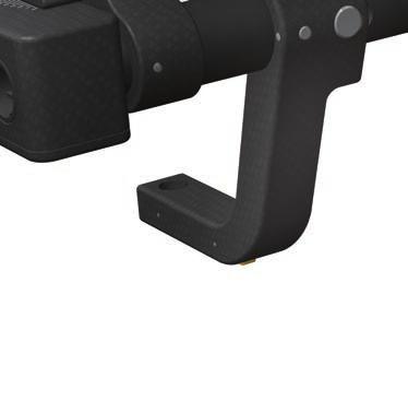
7 END CAP Total Length: 6.85 mm Head Length: 2.5 mm SCREWS Headless PA Screws Length: 65 mm mm available in 5 mm increments 3.5 mm Hex Head Headed Cortical Screws Length: 20 mm - 60 mm available in 5 mm increments 3.5 mm Hex Head mm Varies with length Diameter 5 mm Hex: 3 mm Length 65 mm mm Length 20 mm - 60 mm Major Diameter 7 mm Minor Diameter 5 mm Major Diameter 5 mm Minor Diameter 3.85 mm ACCESSORY INSTRUMENTATION The DynaFrame CF Targeting System is made of high-strength, rigid carbon fiber polyether ether ketone (PEEK) to provide accurate drill targeting and placement of screws along with excellent visibility under fluoroscopy. Frame Operational Features 1. Cam Lever: Pull down to stretch the Compressive Element 2. Stop Wheel: Turn to set the desired length of Compressive Element stretch (0-6 mm) 3. Manual Compression Knob: Rotate clockwise to apply external compression 4. Deployment Base: Use lasermarks to determine amount of manual compression applied (0-6 mm) 5. Compression Tubes: Contain slots to aid in targeting medial-lateral screws 6. PA Targeting Arm: Attach to Compression Tubes to provide accurate placement of Headless PA Screw 7. Outer Tube Brace: Provides additional rigidity to the Targeting Frame 8. Step Numbers: Indicates order of steps involving the Targeting Frame


8 INSTRUMENT TRAY Instrument Part No. Qty Instrument Part No. Qty 1. Anvil Attachment mm Steinmann Pin mm Hex Driver, T-Handle Trocar Tipped Guidewire mm Protection Sleeve Bead Tipped Guidewire mm Protection Sleeve Screw Depth Gauge M6 Connection Screw mm Drill Trocar Obturator mm Drill mm Drill Guide mm Protection Sleeve mm Drill Guide mm Hex Driver Shaft mm Guide Sleeve mm Hex Driver Shaft mm Reamer Head mm Cannulated Drill mm Reamer Head mm Cannulated Drill mm Reamer Head Reamer Shaft mm Reamer Head Targeting Frame mm Reamer Head Blue-Handle Ratchet Driver mm Reamer Head Removal Tool mm Reamer Head Handwheel Wrench mm Reamer Head Note: Additional removal tools available upon request.


9 INDICATIONS The DynaNail TTC Fusion System is indicated for use in tibiotalocalcaneal talocalcaneal (TTC) fusion procedures to treat the following conditions: Post-traumatic and degenerative arthritis Post-traumatic or primary arthrosis involving both ankle and subtalar joints Revision after failed ankle arthrodesis with subtalar involvement Failed total ankle arthroplasty Non-union ankle arthrodesis Rheumatoid hindfoot Absent Talus (requiring tibiocalcaneal arthrodesis) Avascular necrosis of the talus Neuroarthropathy or neuropathic ankle deformity Neuromuscular disease and severe deformity Osteoarthritis Charcot Foot Previously infected arthrosis with confirmed eradication of infection Contraindications Patients with an active local or systemic infection Patients with an active soft tissue infection or osteomyelitis of foot and ankle Patients with severe peripheral vascular disease Patients with an obliterated medullary canal or other conditions that tend to retard healing such as blood supply limitations or previous infections Patients with an insufficient plantar pad Skeletally immature patients where the implant would cross open epiphyseal plates Patients having an intact asymptomatic subtalar joint Patients with significant tibial malalignment (>10 degrees ees in either sagittal or coronal plane) Patients with a dysvascular limb Patients with severe longitudinal deformity Patients with an insufficient quantity or quality of bone to permit fusion of the joints or stabilization of the arthrodesis Patients with conditions that restrict his or her ability or willingness to follow postoperative instructions during the healing process Patients with foreign body sensitivity, suspected or documented metal allergy or intolerance. Where material sensitivity is suspected, appropriate tests should be conducted and sensitivity ruled out prior to implantation 9


![Set the amount of compression by turning Stop Wheel [2] 9. Return lever by pulling up when finished [3] 10.](/docs-images/85/91573077/images/10-6.jpg "Attach Outer Tube Brace and PA Attachment 11. Drill into the calcaneus and insert P-A Headless Screw [4] 12.")
![Drill into the calcaneus and insert L-M Cortical Screw [5] 13. Drill medial-to-lateral into distal interlocking screw hole of the Nail Implant [6] 14.](/docs-images/85/91573077/images/10-7.jpg "Apply External Compression by turning the Manual Compression Knob [7] 15.")
10 QUICK REFERENCE GUIDE The following is a general overview of the DynaNail Surgical Technique intended to be used as an easy reference. A more detailed surgical technique including technical tips and pearls is described in the following pages. Numbers in bold correspond to the numbers marked on the frame and are intended to be used as a guide for the order of steps to be taken with the DynaFrame Targeting System. 1. Assemble Targeting Frame 2. Insert Guidewire into tibial canal 3. Drill entry tunnel with 7 mm and 9 mm Drills 4. Ream to appropriate size using Reamer Shaft and Reamer Heads 5. Load Nail Implant onto Targeting Frame 6. Insert Nail Implant into reamed tibial canal 7. Stretch the Compressive Element by pulling down on Lever [1] 8. Set the amount of compression by turning Stop Wheel [2] 9. Return lever by pulling up when finished [3] 10. Attach Outer Tube Brace and PA Attachment 11. Drill into the calcaneus and insert P-A Headless Screw [4] 12. Drill into the calcaneus and insert L-M Cortical Screw [5] 13. Drill medial-to-lateral into distal interlocking screw hole of the Nail Implant [6] 14. Apply External Compression by turning the Manual Compression Knob [7] 15. (Optional) Insert most proximal tibial Cortical Screw in DynaNail XL Implants. Drill and insert proximal tibial Cortical Screw into proximal interlocking screw hole [8] 16. Insert distal tibial Cortical Screw [9] 17. Release Nail Implant from the Targeting Frame 18. Replace End Cap and close incisions 10


11 SURGICAL TECHNIQUE

* 2. 2.5 mm Fenestration Drill A range of surgical approaches and incisions may be utilized to access the tibiotalar and subtalar joint.")


12 1 Patient Positioning Place the patient in the supine or pseudo-lateral position with the foot at the terminal end of the table. Clear visualization to the plantar aspect of the foot is critical. Be sure to prep and drape above the knee to be able to assess limb rotation. If unaffected, assess contralateral limb for rotational alignment. TECH TIP A trauma triangle with the apex padded or cushioned may be placed under the ankle for ease of drilling and placing screws. 2 Joint Preparation Instruments Used: 1. Steinmann Pin (18)* mm Fenestration Drill A range of surgical approaches and incisions may be utilized to access the tibiotalar and subtalar joint. The surgical approach chosen for joint prep and alignment is dependent upon factors such as the local anatomy, type of deformity, and surgeon preference. Adequate joint preparation and alignment is a critical step for achieving a successful fusion. Denude any remaining cartilaginous surface, paying attention to any angular deformities in the coronal and talocalcaneal joints. If any significant bone gaps are noted, they can be filled with either bone autograft or allograft per surgeon preference. Continue joint preparation until good bone-to-bone apposition is achieved at the talocalcaneal and tibiotalar joints. Meticulous attention should be paid for visual evidence of viable bone on each apposing surface. If in question, the tourniquet should be deflated to evaluate for punctuate bleeding. The 2.5 mm Fenestration Drill may be used to aid in creating viable bleeding bone or feathering the joint surfaces. Provisional fixation with smooth Steinmann Pins to maintain desired alignment may be performed at this time, paying close attention to all three planes (coronal, sagittal, and rotation). Typically, neutral to 7 degree valgus, neutral dorsiflexion-plantarflexion and rotation comparable to the contralateral side is desired. Avoid varus or excessive valgus positioning. To avoid excessive valgus with a neutral ankle, it is recommended to translate the calcaneus medially under the talus. An excessive valgus or too medial insertion point may affect the placement of the calcaneal PA Screw. 12 *(Number) represents corresponding position in Instrument Tray. Refer to page 6.


 To assemble the")


13 3 Nail Entry Site Preparation Make a plantar incision at least 2 cm in length. The incision can be in the longitudinal or transverse direction, according to surgeon preference. Bluntly dissect the soft tissue down to the surface of the calcaneus. Extreme care must be taken to protect the plantar neurovascular structures throughout the procedure. 4 Targeting Frame Assembly Instruments Used: 1. Targeting Frame (30) To assemble the Targeting Frame, slide the Manual Compression Tubes onto the Deployment Base. Push down on the gold latch on top of the Compression Tube arch to lock it in place (A). The Frame is secured in place when the Manual Compression Assembly no longer slides and the latch pops up to its original position. A BEFORE loading the Nail Implant, be sure to check that: The numbered gold Stop Wheel is set to 0 and that the lever is in the upright position to allow the DynaNail Implant to attach to the frame (B). The gold Manual Compression Knob is in the starting position by rotating it fully counter clockwise. This sets the Manual Compression Tubes to the 0 position (C). If the Stop Wheel is not set to zero: pull the lever down, turn the Stop Wheel to 0, and return the lever to its upright position. B C 13
 2. 3.")
 4.")


.")

14 5 Guidewire Insertion Instruments Used: 1. Trocar Tipped Guidewire (19) mm Protection Sleeve (4) mm Protection Sleeve (3) mm Protection Sleeve (24) Assemble the 3.3 mm, 9.5 mm, and 14 mm Protection Sleeves as shown in Inset A. Place the Protection Sleeve Assembly against the plantar surface of the calcaneus. Insert the Trocar Tipped Guidewire (B) into the 3.3 mm Protection Sleeve, taking care that the guidewire tip is contacting the inferior aspect of the calcaneus. Drill the guidewire through the calcaneus and talus into the tibial medullary canal. With the Protection Sleeve abutted against the bone, confirm proper depth has been reached by reading the lasermarks off the back of the Protection Sleeve (C). When satisfied with the guidewire placement, remove the 3.3 mm Protection Sleeve leaving the Trocar Tipped Guidewire in place. TECH TIP Fluoroscopy should be utilized throughout the entire insertion process to ensure centered guidewire placement in the tibial medullary canal on both the anterior and lateral views. A C B 14
 3. 14 mm Protection Sleeve (24) 4.")
 With the 9.")


15 6 Initial Drilling Instruments Used: 1. Trocar Tipped Guidewire (19) mm Protection Sleeve (3) mm Protection Sleeve (24) 4. 7 mm Cannulated Drill (28) 5. 9 mm Cannulated Drill (27) 6. Bead Tipped Guidewire (20) With the 9.5 mm Protection Sleeve still in place, insert the 7 mm Cannulated Drill over the guidewire and drill into the medullary canal. The Trocar-Tipped Guidewire will come out when removing the 7 mm Drill. Replace the Trocar-Tipped Guidewire with the Bead-Tipped Guidewire. Reconfirm with fluoroscopy that the Guidewire is seated in the same position prior to proceeding with the 9 mm Drill. Repeat drilling using the 9 mm Cannulated Drill. Remove the 9.5 mm Protection Sleeve. TECH TIPS It is recommended to drill with the 7 mm Cannulated Drill to just beyond the tibiotalar joint, stopping at the metaphyseal level. Then, drill through the tibial canal using the 9 mm Cannulated Drill. A 2nd Bead-Tipped Guidewire can be inserted into the back of the drill and pushed against the inserted Bead-Tipped Guidewire ensuring it remains in place while pulling out the drill. Do NOT forget to replace the Trocar-Tipped Guidewire with the Bead-Tipped prior to reaming. 15

16 7 Reaming Instruments Used: 1. Bead Tipped Guidewire (20) mm Protection Sleeve (24) 3. Reamer Shaft (29) mm Reamer Heads (10-17) Place the 10 mm Reamer Head onto the Reamer Shaft (A). With the 14 mm Protection Sleeve e still in place against the calcaneus, slide the Reamer assembly over the Bead Tipped Guidewire. Ream into the tibial medullary canal to the depth recommended for the chosen DynaNail length as determined from Table 1 (as read off the 14 mm Protection Sleeve (B)). Once the recommended depth is reached, replace the 10 mm Reamer Head with the 10.5 mm Reamer Head and repeat. Using fluoroscopy, continue progressively reaming in 0.5 mm increments until cortical contact is made within the tibia. It is recommended that the final reaming size be mm larger than the selected implant diameter (Table 2). Use fluoroscopy as necessary to be sure the cortical wall is not compromised. NOTE: The distal end of the DynaNail Implant is larger than the proximal end (12.5 mm), requiring additional reaming on the distal side through both the calcaneus and talus (refer to Table 2). Table 1. Recommended Tunnel Depth Nail Length (mm) Reaming Length (mm) Table 2. Recommended Tunnel Diameter Nail Diameter Proximal End of Nail Distal End of Nail To a depth of 75 mm DynaNail Proximal Diameter (mm) Reaming Diameter (mm) DynaNail Distal Diameter (mm) Reaming Diameter (mm) 10 mm mm


17 TECH TIPS For easier accessibility, the Reamer Heads Caddy can be removed from the tray and placed closer to the operating table. The Reamer Heads are only retained on the Reamer Shaft by the Guidewire and can fall if not held onto the shaft until the reamer head is securely on the Guidewire. Be sure that the Protection Sleeve abuts the calcaneus to ensure accurate depth readings. B A 17
 2.")
")


.")
")

18 8 Implant Attachment Instruments Used: 1. M6 Connection Screw (5) 2. 5 mm Hex Driver Shaft (25) 3. Blue-Handle Ratchet Driver (31) Insert the M6 Connection Screw through the inner cylinder of the Targeting Frame (A). Attach the DynaNail Implant onto the Targeting Frame, taking care to correctly align the keyed slots on the Implant with the pegs on the Targeting Frame (B). Attach the 5 mm Hex Driver Shaft onto the Blue-Handle Ratchet Driver (C) and use the Hex Driver to screw the M6 Connection Screw into the distal end of the DynaNail until the Implant is tight on the Targeting Frame. A C 18 B
 A Remove the Bead Tipped Guidewire and insert the DynaNail into the medullary canal, rotating the Targeting Frame to help advance the")


.")


19 9 Implant Insertion Instruments Used: 1. Anvil Attachment (1) A Remove the Bead Tipped Guidewire and insert the DynaNail into the medullary canal, rotating the Targeting Frame to help advance the Implant. If additional force is required to advance the Implant, slide the Anvil Attachment onto the Targeting Frame (A) and strike the Anvil with a mallet (B). The Anvil Attachment can be removed after the DynaNail Implant is inserted. TECH TIPS Do NOT strike any other part of the frame besides the Anvil Attachment. Hold at least one side of the anvil down in the slot to ensure that it does not slip out and fall. Pay attention to rotation of Nail Implant during insertion. Too medial of an entry point combined with internal rotation may affect the position and purchase of the calcaneal PA screw. B L-M Screw Hole aligned with subtalar joint Distal end of Nail subflush with calcaneus Nail Placement Guidelines: Position the lateral-to-medial calcaneal screw hole as proximal as possible in the calcaneus (after the Compressive Element is stretched in the following step). In this proximal position, the lateral screw gains optimal purchase by targeting the longest possible screw in the widest part of the calcaneus. This proximal position also countersinks the DynaNail as far as possible within the calcaneus. Countersink the distal end of the DynaNail Implant 6 mm in the calcaneus (Refer to X-Ray). The Outer Body will translate distally up to 6 mm as the Compressive Element unloads post-operatively. TECH TIP To achieve optimal lateral-to-medial screw positioning after the Compressive Element is stretched, insert the DynaNail Implant until the lateral-to-medial screw hole is aligned with the subtalar joint (refer to X-Ray). In this case when the Compressive Element is stretched to the maximum 6 mm (Step 10), this screw hole will translate distally by 6 mm, placing it in the optimal proximal position within the calcaneus. 19

")


20 10 Stretch Compressive Element Instruments Used: 1. Targeting Frame (30) Compressive Element visible L-M Screw Hole translated distal into calcaneus Stretch the Compressive Element by pulling the lever into the full downward position (A). Use the Stop Wheel to set the desired amount of compression (up to 6 mm) from the Compressive Element (B, C). For example, setting the Stop Wheel to 6 signifies the Compressive Element is stretched by 6 mm and can therefore unload and maintain compression for up to 6 mm of bone resorption and/or settling. Flip the lever back up into its relaxed position (D). Note the DynaNail s calcaneal screw holes have translated distally and are now in their final position. Confirm desired location of screw holes in the calcaneus under fluoroscopy before continuing. A D B C 20

 2.")
 4.")
 6. 3.")
 7.")
 8.")


21 11 PA Headless Screw Placement Instruments Used: 1. Targeting Frame (30) 2. 8 mm Guide Sleeve (9) 3. 5 mm Drill Guide (7) 4. Trocar Obturator (6) 5. 5 mm Drill (22) mm Hex Driver Shaft (26) 7. Blue-Handle Ratchet Driver (31) 8. Headless PA Screw Slide the Outer Tube Brace onto the Manual Compression Tubes until it locks in place, ensuring the arrow markings are pointed towards the Targeting Frame (A). Be sure that the holes in the Outer Tube Brace align with the holes in the Manual Compression Tubes. A 21
 Attachment to the right")

 joint.")


22 Attach the Posterior-Anterior (PA) Attachment to the right side of the Targeting Frame. The PA Headless Screw should be aimed toward the calcaneocubioid (C-C) joint. If the calcaneus is deformed such that there is limited purchase for the Headless Screw, externally rotate the Targeting Frame so that the PA Attachment targets towards the desired entry point. TECH TIP A trauma triangle can be used here to keep the foot elevated 22


23 Thread the Trocar Obturator into the 8 mm Guide Sleeve (B). Depress the gold trigger on the PA Attachment to insert the Guide Sleeve/Trocar assembly. Make an incision at the Trocar tip and confirm that the Trocar is resting directly against the calcaneus. B 23


 (C).")


24 Leaving the Guide Sleeve in place, replace the Trocar with the 5 mm Drill Guide (indicated with purple stripe) (C). TECH TIPS Leave the Drill Guide just off the bone while drilling to ensure Drill Guide does not push back against the PA Attachment. If patient s leg must be lifted and not using a trauma triangle, hold the leg, NOT the Targeting Frame, to lift. C 24


.")


. TECH TIP After")

25 Insert the 5 mm Drill into the Drill Guide and drill to the desired depth (typically just proximal to the C-C joint). Read the laser markings on the Drill relative to the back of the Drill Guide to determine the appropriate screw length (D). TECH TIP After drilling, advance the Drill Guide directly against the bone for accurate screw length measurement. D 25


.")


26 Attach one 3.5 mm Hex Driver Shaft to the Blue-Handle Ratchet Driver and a second 3.5 mm Hex Driver to a power drill. Remove the 5 mm Drill and Drill Guide from the Guide Sleeve. Insert the Headless PA Screw through the Guide Sleeve using the 3.5 mm Hex Driver loaded on the power drill until the screw has passed through the Nail Implant. Then switch to the Blue-Handle Ratchet Driver to continue to advance the screw until it is flush with the posterior calcaneus (E). Remove the Guide Sleeve from the PA Attachment. Remove the PA Attachment from the Targeting Frame. TECH TIP The Headless PA Screw does not provide tactile feedback to indicate when it is fully inserted. Use the laser line on the 3.5 mm Hex Driver to determine if the PA Screw is fully inserted. When the laser line approaches the back of the Guide Sleeve, use lateral flouroscopy while advancing the final turns, ensuring the screw tip does not breach the C-C joint. E 26
 3. 4 mm Drill Guide (8) 4. 4 mm Drill (23) 5.")
 8.")


27 12 Calcaneal L-M Screw Placement Instruments Used: 1. 8 mm Guide Sleeve (9) 2. Trocar Obturator (6) 3. 4 mm Drill Guide (8) 4. 4 mm Drill (23) 5. Screw Depth Gauge (Optional) (21) mm Hex Driver Shaft (26) 7. Blue-Handle Ratchet Driver (31) 8. Cortical Screw Thread the Trocar into the 8 mm Guide Sleeve. Insert the 8 mm Guide Sleeve and Trocar assembly into the lateral side of the Targeting Frame. Make an incision at the Trocar tip and abut the Trocar against the calcaneus. Distal retraction of the peroneal tendons can sometimes be done to allow direct contact of the Trocar against bone. Leaving the Guide Sleeve in place, replace the Trocar with the 4 mm Drill Guide (indicated with a green stripe) (A). Ensuring the Drill Guide is NOT resting against the bone, drill bicortical with the 4 mm Drill and measure the screw length off the Drill Guide in the same manner as previously described in Step 11. Alternatively, the Screw Depth Gauge can be used to determine screw length. Note that the Screw Depth Gauge must also be read off of the Drill Guide as it abuts the bone. TECH TIP Due to the soft bone in the medial calcaneus, it might be difficult to determine whether the drill has breached the far lateral cortex through tactile feedback. Assess drill position using fluoroscopy. A 27


28 Remove the 4 mm Drill Guide. Insert the Cortical Screw through the 8 mm Guide Sleeve using the 3.5 mm Hex Driver as described in Step 11. Use fluoroscopy to determine when desired depth is reached and the screw is fully seated. 28
 (8) 3. Trocar Obturator (6) 4.")


29 13 Apply External Compression Instruments Used: 1. 8 mm Guide Sleeve (x 2) (9) 2. 4 mm Drill Guide (x 2) (8) 3. Trocar Obturator (6) 4. 4 mm Drill (23) Thread the Trocar into the 8 mm Guide Sleeve. Insert the 8 mm Guide Sleeve and Trocar assembly into the more distal tibial interlocking screw hole on the medial side of the Targeting Frame (passing through the Outer Tube Brace). Make an incision at the Trocar tip and advance the Trocar down to bone. Leaving the Guide Sleeve in the Targeting Frame, replace the Trocar with the 4 mm Drill Guide in the Guide Sleeve. e. TECH TIPS The 4 mm Drill Guide should be placed just off the bone to ensure that the targeting frame is floating freely during drilling. Do NOT place the second 4 mm Drill Guide on lateral side of frame (next step) until AFTER advancing the Drill through the nail. The fibula can interact with the lateral Drill Guide, which can push the Targeting Frame out of alignment. If not using a trauma triangle, make sure the targeting tubes are not resting on any table or pillows. If using bumps or towels, move them to underneath ankle. Drilling from the medial side, pass a fresh 4 mm Drill through the tibia and across the Targeting Frame. Thread another 4 mm Drill Guide into a second 8 mm Guide Sleeve and insert the Guide assembly into the distal hole on the lateral side of the Targeting Frame so that it abuts against the bone. Continue to insert the 4 mm Drill into the Drill Guide on the lateral side (A). Leave the drill in place and rotate the Manual Compression Knob clockwise to apply compression across the joint (B). The approximate amount of applied external compression can be determined by reading the lasermarks on the Targeting Frame (C). Leave the Drill in place while proceeding to Step 14. NOTE: If external compression is not desired, proceed to the Quick Compress Technique on page 35 for tibial screw placement. B C A 29
 2. Trocar Obturator (6) 3. 4 mm Drill Guide (8) 4.")
 7.")


.")
30 14 Proximal Tibial Screw Placement Instruments Used: 1. 8 mm Guide Sleeve (9) 2. Trocar Obturator (6) 3. 4 mm Drill Guide (8) 4. 4 mm Drill (23) mm Hex Driver Shaft (26) 6. Blue Handle Ratchet Driver (31) 7. Cortical Screw Thread the Trocar into a third 8 mm Guide Sleeve. Place the 8 mm Guide Sleeve and Trocar Assembly in the most proximal hole on the medial side of the Targeting Frame. Make an incision at the Trocar tip and advance down to bone. Leaving the Guide Sleeve in place, replace the Trocar with the 4 mm Drill Guide (indicated with a green stripe). Drill using a fresh 4 mm Drill, determine appropriate Cortical Screw length, and insert Cortical Screw as described in Step 12. Remove the 8 mm Guide Sleeve from the Targeting Frame. 30
 Instruments Used: 1.")
 4.")
 6.")


31 15 OPTIONAL Proximal Tibial Screw Placement (for DynaNail XL Implants Only) Instruments Used: 1. Cortical Screw 2. 4 mm Free-Hand Drill 3. 8 mm Guide Sleeve (9) 4. Free-Hand Screw Depth Gauge mm Hex Driver Shaft (26) 6. T-Handle Ratchet Driver (31) For 260 mm and 300 mm length Implants, a screw may also be free-handed into the most proximal tibial screw hole. This screw can also be a substitute for the tibial screw described in Step 15. Drill using the 4 mm Freehand Drill in the most proximal tibial screw hole using perfect circles technique under fluoroscopy. Determine the appropriate screw length by inserting the Free-Hand Screw Depth Gauge. Insert the Cortical Screw as described in Step 12. Use fluoroscopy to determine when desired depth is reached and the screw is fully seated. Free-Hand Screw Depth Gauge 31

 3.")


.")

32 16 Distal Tibial Screw Placement Instruments Used: mm Hex Driver Shaft (26) 2. Blue Handle Ratchet Driver (31) 3. Cortical Screw Relieve the compression on the 4 mm Drill by turning the Manual Compression Knob back counter clockwise until it rotates freely (A), but do not force the wheel back until it reads zero. Remove the 4 mm Drill. Determine the appropriate screw length and insert the Cortical Screw as described in Step 11 (B). Confirm screw placement, anatomic alignment, and apposition of fusion surfaces under fluoroscopy prior to removing Targeting Frame. A B 32


 Unscrew the")


33 17 Release Nail Instruments Used: 1. 5 mm Hex Driver Shaft (25) 2. Blue Handle Ratchet Driver (31) Unscrew the M6 Connection Screw using the 5 mm Hex Driver (A) releasing the DynaNail Implant from the Targeting Frame (B). B A 33


34 18 Add End Cap Instruments Used: 1. 3 mm Hex Drive, T-Handle (2) 2. End Cap Thread the End Cap into the distal end of the DynaNail Implant using the 3 mm T-Handle Hex Driver. Close incisions per surgeon preference. NOTE: On the final fluoroscopy shot, note the distal position of the Calcaneal Screws in the Sliding Element slots and the Sliding Element protruding plantar form Outer Nail Body, indicating the Compressive Element is in its stretched, activated state. 34


35 QUICK COMPRESS TECHNIQUE (OPTIONAL) If a surgeon would like to bypass external manual compression, the following steps may replace Steps described above. Depending upon the choice of tibial screw placement, this alternate technique also allows for additional dynamization even after full recovery of the Compressive Element. NOTE: While the Compressive Element will provide post-operative compression, applying manual compression helps ensure the joints are tightly compressed intra-operatively so that the Compressive Element does not recover until resorption occurs post-surgery. Therefore, it is recommended that this alternate technique only be adopted when the joints appear visually compressed intra-operatively. Indications include if a surgeon wants to avoid the lateral plantar neurovascular bundle, reduce the risk of a stress riser at the screw when drilling in the tibia, or wishes to drill only one tibial screw hole instead of two. Patients with large bony defects who might receive a bulk allograft, or are immunocompromised with poor bone healing capacity might not be suitable for this technique. NOTE: Though not using the Manual Compression feature, the Compression Wheel must still be zeroed in order to properly load the Nail Implant. 35


 Slide the")


36 13b Compress Arthrodesis Site Instruments Used: 1. Anvil Attachment (1) Slide the Anvil Attachment onto the Targeting Frame (A) and strike the Anvil with a mallet to apply compression to the arthrodesis site. TECH TIP DO NOT strike any other part of the frame besides the Anvil Attachment. 36

 3.")
 If")


37 14b Distal Tibial Screw Placement Instruments Used: 1. 5 mm Cortical Screw 2. 4 mm Drill (23) 3. 4 mm Drill Guide (8) 4. 8 mm Guide Sleeve (9) If automatic dynamization is desired, drill a hole from the medial side into the distal tibial oblong slot of the DynaNail Implant until the Drill has breached the lateral side of the tibia. Insert a 5 mm Cortical Screw as described in Step


38 15b OPTIONAL: Proximal Tibial Screw Placement If static locking is desired, drill a hole into one of the proximal tibial screw holes of the DynaNail Implant and insert a 5 mm Cortical Headed Screw as described in Step 12. This step may replace Step 15b such that there is only one screw in the proximal tibial hole, if so desired. Proceed to Step 17 in the original technique to finish the procedure. 38


39 ORDERING INFORMATION DYNANAIL IMPLANTS DYNANAIL SINGLE USE INSTRUMENTS Part No. Description Part No. Description DynaNail, 10 mm x 22 cm DynaNail, 12 mm x 22 cm DynaNail XL, 10 mm x 26 cm DynaNail XL, 12 mm x 26 cm DynaNail XL, 10 mm x 30 cm DynaNail XL, 12 mm x 30 cm Headed Cortical Screw, 5.0 mm x 20 mm Headed Cortical Screw, 5.0 mm x 25 mm Headed Cortical Screw, 5.0 mm x 30 mm Trocar-Tipped Guidewire, 3.1 mm x 400 mm Bead-Tipped Guidewire, 3.1 mm x 500 mm Bead-Tipped Guidewire, 3 mm x 800 mm Threaded Guidewire, 3.1 mm x 400 mm Steinmann Pin, 2 mm x 9" mm Drill mm Stepped Drill mm x 6" Fenestration Drill mm x 6" Free-Hand Drill Headed Cortical Screw, 5.0 mm x 35 mm Headed Cortical Screw, 5.0 mm x 40 mm Headed Cortical Screw, 5.0 mm x 45 mm Headed Cortical Screw, 5.0 mm x 50 mm Headed Cortical Screw, 5.0 mm x 55 mm Headed Cortical Screw, 5.0 mm x 60 mm Headless PA Screw, 5.0 mm x 65 mm Headless PA Screw, 5.0 mm x 70 mm Headless PA Screw, 5.0 mm x 75 mm Headless PA Screw, 5.0 mm x 80 mm Headless PA Screw, 5.0 mm x 85 mm Headless PA Screw, 5.0 mm x 90 mm Headless PA Screw, 5.0 mm x 95 mm Headless PA Screw, 5.0 mm x 100 mm Headless PA Screw, 5.0 mm x 105 mm Headless PA Screw, 5.0 mm x 110 mm End Cap 39


40 This brochure is presented to demonstrate the surgical techniques utilized by Thomas P. San Giovanni, M.D. MedShape, as the manufacturer of this device, does not practice medicine and does not recommend this or any other surgical technique for use on a specific patient. The surgeon who performs any procedure is responsible for determining and utilizing the appropriate techniques for such procedure for each individual patient. MedShape is not responsible for selection of the appropriate surgical technique to be utilized for an individual patient. Always refer to the package insert, product label and/or product instructions prior to using any MedShape product. For further product information or to arrange a product demonstration, please contact your local MedShape representative or call Customer Service at You can also visit MedShape, Inc Northside Drive, NW Suite 440 Atlanta, GA T: F: CAUTION: Federal (USA) law restricts this device to sale by or on the order of a physician. MedShape, Inc., All rights reserved. Printed in the USA. Pa at.: MK Rev 02. Issued 12/2017. DynaNail is a registered trademark of Me edshape, Inc. DynaFrame is a trademark of MedShape, Inc. All other trademarks are trademarks of their respective owners and holders.
The Latest Breakthrough in TTC Fusion Technology
 The Latest Breakthrough in TTC Fusion Technology Treatment of Hindfoot Non-Union with DynaNail TTC Fusion System A CASE REPORT Dr. L. Daniel Latt, MD, PhD Background The DynaNail TTC Fusion System is intended
The Vilex FUZETM. Dual Thread Screw & Intramedullary Nail in One Implant. The Ultimate TTC Arthrodesis Internal Fixator
 The Vilex FUZETM Dual Thread Screw & Intramedullary Nail in One Implant The Ultimate TTC Arthrodesis Internal Fixator Introduction The Vilex FUZE TM TTC Arthrodesis Compression Nail combines the attributes
Foot & Ankle T2. Ankle Arthrodesis Nail. Foot & Ankle
 Foot & Ankle T2 Ankle Arthrodesis Nail Operative Technique Foot & Ankle 1 Ankle Arthrodesis Nailing System This publication sets forth detailed recommended procedures for using Stryker devices and instruments.
Arthrodesis of the Ankle
 TM Arthrodesis of the Ankle Plantar View of the Foot 1. Make a lateral incision to expose the tibia-talus joint and the talo-calcaneal joint. Prepare the arthrodesis sites surgically with a rasp or an
Surgical Technique Guide
 Guide CAUTION: Federal Law (USA) restricts this device to sale by or on the order of a physician. INDICATIONS FOR USE The Align Anterior Ankle Fusion Plate is intended to facilitate arthrodesis of the
Surgical Technique. Customer Service:
 Patent and Patent Pending CAUTION: Federal Law (USA) restricts this device to sale by or on the order of a physician. INDICATIONS FOR USE The Axis Charcot Fixation System in diameters of 5.5, 6.5 and 7.5mm
Surgical Technique 4.5/8.5MM BEAMING SYSTEM. Customer Service:
 Patent and Patent Pending CAUTION: Federal Law (USA) restricts this device to sale by or on the order of a physician. INDICATIONS FOR USE The 4.5/8.5 screw system is intended for fixation arthrodesis of
Conventus CAGE PH Surgical Techniques
 Conventus CAGE PH Surgical Techniques Conventus Orthopaedics The Conventus CAGE PH (PH Cage) is a permanent implant comprised of an expandable scaffold, made from nitinol and titanium, which is deployed
Lateral TTC Plate SURGICAL TECHNIQUE
 MAXLOCK EXTREME Lateral TTC Plate SURGICAL TECHNIQUE Contents Overview 2 Exposure 3 Surgical Technique 4 Implants and Instruments 10 11 Proper surgical procedures and techniques are the responsibility
TABLE OF CONTENTS. 2 (8144 Rev 2)
") 1 (8144 Rev 2) TABLE OF CONTENTS Introduction Conventus CAGE TM - Proximal Humerus...3 Indications and Contraindications...4 Surgical Summary...5 Patient Positioning & Approach...6 Surgical Technique Plate
1 (8144 Rev 2) TABLE OF CONTENTS Introduction Conventus CAGE TM - Proximal Humerus...3 Indications and Contraindications...4 Surgical Summary...5 Patient Positioning & Approach...6 Surgical Technique Plate
Surgical Technique Guide
 Sacroiliac Joint Fusion System Surgical Technique Guide Moving Life Forward Table of Contents SiCure Implant Overview...2 SiCure System Information...3 X-ray Basics...4 Patient Positioning....5 Surgical
DEVELOPED BY MEDSHAPE, INC. IN CONJUNCTION WITH PATRICK ST. PIERRE, M.D. BICEPS TENODESIS ARTHROSCOPIC AND SUBPECTORAL SURGICAL TECHNIQUE
 ! SURGICAL TECHNIQUE! DEVELOPED BY MEDSHAPE, INC. IN CONJUNCTION WITH PATRICK ST. PIERRE, M.D. ARTHROSCOPIC AND SUBPECTORAL BICEPS TENODESIS SURGICAL TECHNIQUE BICEPS TENODESIS Indications Tenodesis of
Surgical Technique. CONQUEST FN Femoral Neck Fracture System
 Surgical Technique CONQUEST FN Femoral Neck Fracture System Table of Contents Introduction... 3 Indications... 3 Product Overview... 4 Surgical Technique... 5 Patient Positioning... 5 Reduce the Fracture...
Orthopedic Bone Nail System - Distal Femoral Nail Surgical Technique Manual
 Orthopedic Bone Nail System - Distal Femoral Nail Surgical Technique Manual Note: The surgical procedures should be performed under the guidance of qualified skilled orthopedic surgeons, and this surgical
GENERAL TECHNIQUE GUIDE
 GENERAL TECHNIQUE GUIDE PRODUCT OVERVIEW The Eclipse Soft Tissue Anchor employs MedShape s shape memory PEEK Altera technology for soft tissue fixation procedures in the shoulder, elbow, knee, hand & wrist,
Distal Cut First Femoral Preparation
 Surgical Technique Distal Cut First Femoral Preparation Primary Total Knee Arthroplasty LEGION Total Knee System Femoral preparation Contents Introduction...3 DCF femoral highlights...4 Preoperative planning...6
TRIGEN Hindfoot Fusion Nail Surgical Technique
 Surgical Technique TRIGEN Hindfoot Fusion Nail Surgical Technique As described by: Thomas A. Russell, MD Roy W. Sanders, MD John S. Early, MD Contents Design Rationale...3 Indications...3 Design Features...4
Zimmer ITST Intertrochanteric/ Subtrochanteric Fixation System. Abbreviated Surgical Technique
 Zimmer ITST Intertrochanteric/ Subtrochanteric Fixation System Abbreviated Surgical Technique ITST System Abbreviated Surgical Technique Indications The ITST Intramedullary Nail is indicated for use in
GREENS SURGICALS. Redefining Excellence INSTRUMENT SYSTEM PREPARED BY: DR. VINAY KUMAR
 GREENS SURGICALS Redefining Excellence TIBIA AND FEMUR INSTRUMENT SYSTEM PREPARED BY: DR. VINAY KUMAR OPERATIVE TECHNIQUES INDEX SR.NO CONTENTS 1 LIST OF INSTRUMENT FOR TIBIA AND FEMUR. 2 RADIO GRAPH OF
Zimmer Trabecular Metal Ankle Interpositional Spacer and Trabecular Metal Ankle Fusion Spacer
 Zimmer Trabecular Metal Ankle Interpositional Spacer and Trabecular Metal Ankle Fusion Spacer Surgical Technique 2 Zimmer Trabecular Metal Ankle Interpositional Spacer and Trabecular Metal Ankle Fusion
STRENGTH FROM WITHIN. Surgical Technique for Representatives
 STRENGTH FROM WITHIN Surgical Technique for Representatives Table of Contents PREOPERATIVE TEMPLATING... p.3 OUTRIGGER DRILL GUIDE OVERVIEW... p.4 PATIENT POSITIONING...p.5 STEP 1: REDUCE THE FRACTURE...p.5-6
Correction System. Surgical Technique
 Nextra Hammertoe Correction System Surgical Technique Maximized Bone Purchase* Stable and Secure Phalanx Optimized Screw Design Adjustable Bone-to-Bone Apposition Progressive Ratchet Tightening Mechanism
S U R G I C A L T E C H N I Q U E David A. McQueen, MD Return to Menu
 S U R G I C A L T E C H N I Q U E David A. McQueen, MD TOTAL KNEE INSTRUMENTS Wichita Fusion Nail Introduction...1 Preoperative Planning...2 Surgical Technique...3-8 Wichita Fusion Nail Surgical Technique
3. PATIENT POSITIONING & FRACTURE REDUCTION 3 8. DISTAL GUIDED LOCKING FOR PROXIMAL NAIL PROXIMAL LOCKING FOR LONG NAIL 13
 Contents IMPLANT FEATURES 2 1. INDICATIONS 3 2. PRE-OPERATIVE PLANNING 3 3. PATIENT POSITIONING & FRACTURE REDUCTION 3 4. INCISION 4 5. ENTRY POINT 4-6 6. PROXIMAL NAIL INSERTION 6-7 7. PROXIMAL LOCKING
Wichita Fusion Nail Surgical Technique. David A. McQueen, MD
 Wichita Fusion Nail Surgical Technique David A. McQueen, MD The patented design with a dual advantage Generates compression intraoperatively Innovative compression screw (a) locks femoral and tibial components
InCoreTM Lapidus System
 InCoreTM Lapidus System Precision Guided Correction Surgical Technique InCore TM Lapidus System Precision Guided Correction Tri-Planar Correction Targeting Guide is intended to aid and stabilize angular/rotational
Phoenix Tibial Nail System
 Surgical Technique Phoenix Tibial Nail System Featuring CoreLock Technology Each nail features CoreLock Technology, a preassembled, embedded locking mechanism for locking all proximal oblique screws, which
Surgical Technique. Forearm Fracture Solutions
 Surgical Technique Forearm Fracture Solutions Acumed is a global leader of innovative orthopaedic and medical solutions. We are dedicated to developing products, service methods, and approaches that improve
Surgical Technique. Targeter Systems Overview
 Surgical Technique Targeter Systems Overview PERI-LOC Locked Plating System Targeter Systems Overview Table of contents Product overview... 2 Introduction... 2 Indications... 2 Design features and benefits...
Zimmer Natural Nail System
 Zimmer Natural Nail System Antegrade Femoral Nail Surgical Technique (Piriformis Fossa & Greater Trochanteric Approaches) Zimmer Natural Nail System Antegrade Femoral Surgical Technique 1 Zimmer Natural
The AperFix II System
 The AperFix II System A Complete Anatomic Solution Transtibial Surgical Technique 2 AperFix II System Transtibial Surgical Technique Figure 1 A Complete Anatomic Solution The Cayenne Medical AperFix and
Case Report. Antegrade Femur Lengthening with the PRECICE Limb Lengthening Technology
 Case Report Antegrade Femur Lengthening with the PRECICE Limb Lengthening Technology S. Robert Rozbruch, MD Hospital for Special Surgery New York, NY, USA ABSTRACT This is a case illustrating a 4.5 cm
Correction System. Surgical Technique
 Nextra Hammertoe Correction System Surgical Technique Maximized Bone Purchase* Stable and Secure Phalanx Optimized Screw Design Adjustable Bone-to-Bone Apposition Progressive Ratchet Tightening Mechanism
System. Humeral Nail. Surgical Technique
 System Humeral Nail Surgical Technique Contents IMPLANT FEATURES 2 1. INDICATIONS 3 2. PRE-OPERATIVE PLANNING 3 3. PATIENT POSITIONING & FRACTURE REDUCTION 3 4. INCISION 4 5. ENTRY POINT 4-6 6. PROXIMAL
Surgical Technique. Fibula Rod System
 Surgical Technique Fibula Rod System Acumed is a global leader of innovative orthopaedic and medical solutions. We are dedicated to developing products, service methods, and approaches that improve patient
Zimmer NexGen MIS Tibial Component. Cemented Surgical Technique IMAGE TO COME
 Zimmer NexGen MIS Tibial Component Cemented Surgical Technique IMAGE TO COME Zimmer NexGen MIS Tibial Component Cemented Surgical Technique 1 Zimmer NexGen MIS Tibial Component Cemented Surgical Technique
wave Calcaneal Fracture Plate
 wave Calcaneal Fracture Plate s u r g i c a l t e c h n i q u e Tornier WAVE Calcaneal fracture plate system surgical procedure Indications for Use: The Tornier Calcaneal Fracture Plate System is indicated
AcUMEDr. FoREARM ROD SYSTEM
 AcUMEDr FoREARM ROD SYSTEM FoREARM ROD SYSTEM Since 1988 Acumed has been designing solutions to the demanding situations facing orthopedic surgeons, hospitals and their patients. Our strategy has been
PediLoc 3.5mm and 4.5mm Contour Femur Plate Surgical Technique
 PediLoc 3.5mm and 4.5mm Contour Femur Plate Surgical Technique Surgical Technique Contour Femur Plate The technique description herein is made available to the healthcare professional to illustrate the
Aesculap Targon TX. Intramedullary Nail for Tibial Fractures...going to X-tremes. Aesculap Orthopaedics
 Aesculap Targon TX Intramedullary Nail for Tibial Fractures...going to X-tremes Aesculap Orthopaedics Surgical Technique Preoperative Planning KH483 X-ray template Targon TX (KH483200 : 375 mm-420 mm KH48320
Technique Guide. SureLock Distal Targeting Device. C-arm guided targeting for trochanteric fixation nail.
 Technique Guide SureLock Distal Targeting Device. C-arm guided targeting for trochanteric fixation nail. Table of Contents Introduction SureLock Distal Targeting Device 2 Surgical Technique Preoperative
Knee Surgical Technique
 Knee Surgical Technique COMPASS Universal Hinge by Jimmy Tucker, M.D. Orthopaedic Surgeon Director, Arkansas Sports Medicine, P.A. Little Rock, Arkansas Table of contents Design features 3 Indications
Biomet Large Cannulated Screw System
 Biomet Large Cannulated Screw System s u r g i c a l t e c h n i q u e A Complete System for Simplified Fracture Fixation 6.5mm & 7.3mm The Titanium, Self-drilling, Self-tapping Large Cannulated Screw
Surgical Technique Carpal Fusion
 Carpal Fusion Patent and Patent Pending CAUTION: Federal Law (USA) restricts this device to sale by or on the order of a physician. INDICATIONS FOR USE The Extremity Medical Lag Screw and X-Post System
Fibula Rod System. Lateral Malleolus Fracture Indications:
 Fibula Rod System Fibula Rod System Since 1988, Acumed has been designing solutions for the demanding situations facing orthopaedic surgeons, hospitals and their patients. Our strategy has been to know
TIBIAL NAILING SYSTEM OPTIONS MADE EASY
 S U R G I C A L T E C H N I Q U E TIBIAL NAILING SYSTEM OPTIONS MADE EASY TABLE OF CONTENTS DESIGN SUMMARY INSTRUMENT OVERVIEW AND JIG OPTIONS 1 2 ENTRY AND CANAL PREP NAIL INSERTION LOCKING NAIL REMOVAL
Merete PlantarMAX Lapidus Plate Surgical Technique. Description of Plate
 Merete PlantarMAX Lapidus Plate Surgical Technique Description of Plate Merete Medical has designed the PlantarMax; a special Plantar/Medial Locking Lapidus plate which places the plate in the most biomechanically
The Titanium Tibial Nail System
 The Titanium Tibial Nail System Solid Tibial Nails (UTN) and Cannulated Tibial Nails (CTN) Surgical Technique This publication is not intended for distribution in the USA. Instruments and implants approved
OSS Orthopedic Salvage System Compress Device. Surgical Technique
 OSS Orthopedic Salvage System Compress Device Surgical Technique Table of Contents Quick Reference Guide... 2 Device Description... 3 Resection... 4 No Face Adapter Provisional Construct... 4 Canal Preparation...
TITANIUM TIBIAL NAIL SySTEM
 TITANIUM TIBIAL NAIL SySTEM Solid and Cannulated Nails SURGICAL TEChNIqUE Table of contents Introduction Indications 2 Preoperative Implant Selection 6 Surgical Technique Instruments for Opening the Tibia
JuggerLoc Bone-to-Bone System for Ankle Syndesmosis Fixation. Surgical Technique
 JuggerLoc Bone-to-Bone System for Ankle Syndesmosis Fixation Surgical Technique Table of Contents Position and Preparation... 2 Incision... 2 Fracture Reduction... 2 Drill Fibula and Tibia... 3 JuggerLoc
Concept of Tibiotalocalcaneal Fusion with a IIIrd Generation Intramedullary Nail
 June 2006 Page 1 of 6 Concept of Tibiotalocalcaneal Fusion with a IIIrd Generation Intramedullary Nail Thomas Mückley*, M.D., Alexander Petrovitch, M.D., Sebastian Ullm*, Kajetan Klos* Gunther O. Hofmann*
U2 PSA. Revision Knee. Surgical Protocol
 U2 PSA TM Revision Knee Surgical Protocol Table of Contents 1 Component Removal... 1 2 Tibial Preparation... 1 2.1 Tibial Canal Preparation... 1 2.2 Proximal Tibial Resection... 2 2.3 Non Offset Tibial
Ratcheting Compression Plating System. Surgical Technique
 Ratcheting Compression Plating System Surgical Technique Acumed is a global leader of innovative orthopaedic and medical solutions. We are dedicated to developing products, service methods, and approaches
NeoGen Tibia Nail System
 NeoGen Tibia Nail System LESS IS MORE TE-2070-03 Surgical Technique BLE OF CONTENT Preface Surgical Technique Appendix Products Information Patient Preparation Entry Portal Fracture Reduction Canal Preparation
SURGICAL TECHNIQUE GUIDE: JONES FRACTURE USING THE PRECISION JONES FRACTURE SCREW SYSTEM
 PRODUCT DESCRIPTION The PRECISION Jones Fracture Screw System offers extensive options of Type II Anodized Titanium screws. System-specific instrumentation is designed to address procedural challenges
NeoGen Femoral Nail System
 NeoGen Femoral Nail System LESS IS MORE TE-2070-04 Surgical Technique BLE OF CONTENT Preface Standard Femoral Mode Recon Mode Post-Operative Management Appendix Products Information Indication Patient
CASE REPORT. Antegrade tibia lengthening with the PRECICE Limb Lengthening technology
 CASE REPORT Antegrade tibia lengthening with the PRECICE Limb Lengthening technology Austin T. Fragomen, M.D. Hospital for Special Surgery New York, NY 1 1 PR O D U CTS CONDITION Nonunion of an attempted
Sirus Antegrade Femoral Nail System Surgical Technique
 Sirus Antegrade Femoral Nail System Surgical Technique The Cannulated Titanium Nail with Anatomical Shape and Lateral Entry Point Disclaimer This document is intended exclusively for experts in the field,
Technique Guide. *smith&nephew N8TIVE ACL Anatomic ACL Reconstruction System
 Technique Guide *smith&nephew N8TIVE ACL Anatomic ACL Reconstruction System N8TIVE ACL System The N8TIVE ACL Anatomic Reconstruction System provides a novel and simple approach to ACL repair. The N8TIVE
LCP Anterolateral Distal Tibia Plate 3.5. The low profile anatomic fixation system with optimal plate placement and angular stability.
 LCP Anterolateral Distal Tibia Plate 3.5. The low profile anatomic fixation system with optimal plate placement and angular stability. Technique Guide LCP Small Fragment System Table of Contents Introduction
PediNail Pediatric Femoral Nail
 PediNail Pediatric Femoral Nail Surgical Technique Table of Contents Indications...3 Patient Positioning...3 Approach...4 Reaming...5 Nail Placement...6 Proximal Interlocking...7 Distal Interlocking...8
TRK REVISION KNEE Surgical Technique
 1 TRK REVISION KNEE Surgical Technique 1. 2. 3. 4. 5. 6. 7. 8. 9. 10. INTERCONDYLAR RESECTION...... page FEMORAL STEM...... page NON CEMENTED FEMORAL STEM...... page TRIAL FEMORAL COMPONENTS...... page
Technique Guide. 3.5 mm LCP Low Bend Medial Distal Tibia Plate Aiming Instruments. Part of the 3.5 mm LCP Percutaneous Instrument System.
 Technique Guide 3.5 mm LCP Low Bend Medial Distal Tibia Plate Aiming Instruments. Part of the 3.5 mm LCP Percutaneous Instrument System. Table of Contents Introduction 3.5 mm LCP Low Bend Medial Distal
PediLoc 3.5mm and 4.5mm Bowed Femur Plate Surgical Technique
 PediLoc 3.5mm and 4.5mm Bowed Femur Plate Surgical Technique 2957 Bow Broch_REV_B.indd 1 2/10/11 12:47 PM Surgical Technique Bowed Femur Plate The technique description herein is made available to the
CANNULINK. Intraossous Fixation System SURGICAL TECHNIQUE
 CANNULINK Intraossous Fixation System SURGICAL TECHNIQUE Contents Chapter 1 4 Introduction The CANNULINK Advantage Indications for Use Preoperative Planning Chapter 2 5 Surgical Technique CANNULINK Standard
Locking Ankle Plating System. Surgical Technique
 Locking Ankle Plating System Surgical Technique Acumed is a global leader of innovative orthopaedic and medical solutions. We are dedicated to developing products, service methods, and approaches that
Double Engine Orthopedic Bone Nail System Universal Humeral Nail
 Double Engine Orthopedic Bone Nail System ----------- Universal Humeral Nail Surgical Technique Manual Note: The surgical procedures should be performed under the guidance of qualified skilled orthopedic
LCP Anterolateral Distal Tibia Plate 3.5. The low profile anatomic fixation system with optimal plate placement and angular stability.
 LCP Anterolateral Distal Tibia Plate 3.5. The low profile anatomic fixation system with optimal plate placement and angular stability. Technique Guide LCP Small Fragment System Table of Contents Introduction
A Locking IM Rod that won't back out. Simple and straight to the point! SURGICAL TECHNIQUE
 A Locking IM Rod that won't back out. Simple and straight to the point! SURGICAL TECHNIQUE The SLIM (Simple Locking IntraMedullary) System is a new generation of pediatric orthopedic nails specifically
Technique Guide Hammertoe Correction System
 Technique Guide Hammertoe Correction System TM The ToeMATE Hammertoe Correction System is an easy to implant bone screw system intended for the correction of hammertoe deformity. It is provided in a complete
Integra SURGICAL TECHNIQUE. Panta Panta XL Arthrodesis Nail System PRODUCTS FOR SALE IN EUROPE, MIDDLE-EAST AND AFRICA ONLY
 Integra Panta Panta XL Arthrodesis Nail System SURGICAL TECHNIQUE Panta Panta XL Arthrodesis Nail System Table of contents Design rationale... 04 Indications... 04 Implant description... 05 Instruments
Surgical Technique. Calcaneal Locking Plate
 Surgical Technique Calcaneal Locking Plate PERI-LOC Locked Plating System Calcaneal Locking Plate Surgical TechniqueCatalog Infor Table of Contents Introduction...2 Indications...3 Plate Features...3 Patient
Zimmer Small Fragment Universal Locking System. Surgical Technique
 Zimmer Small Fragment Universal Locking System Surgical Technique Zimmer Small Fragment Universal Locking System 1 Zimmer Small Fragment Universal Locking System Surgical Technique Table of Contents Introduction
THE NATURAL FIT. Surgical Technique. Hip Knee Spine Navigation
 THE NATURAL FIT Surgical Technique Hip Knee Spine Navigation MiniMAX Surgical Technique Hip Knee Spine Navigation INTRODUCTION The MiniMAX TM is a cementless anatomic stem available in 9 right sizes and
Surgical Technique Guide
 Surgical Technique Guide Minimally Invasive, Intramedullary Device For Distal Radius Fragility Fractures The Sonoma WRx Wrist Fracture Repair Device is flexible, inserting easily through a small incision
DARCO. Bow 2 Plate SURGIC AL TECHNIQUE
 DARCO Bow 2 Plate SURGIC AL TECHNIQUE Contents 2 Preface 3 Chapter 1 4 Chapter 2 5 6 7 8 9 Appendix 10 10 11 Intended Use Indications/Contraindications Design Rationale Preoperative Planning Surgical Technique
Technique Guide. LCP Proximal Femoral Hook Plate 4.5/5.0. Part of the LCP Periarticular Plating System.
 Technique Guide LCP Proximal Femoral Hook Plate 4.5/5.0. Part of the LCP Periarticular Plating System. Table of Contents Introduction Features and Benefits 2 AO ASIF Principles 4 Indications 5 Surgical
humerus InSafeLOCK Nail
 humerus InSafeLOCK Nail Introduction Content Humerus InSafeLOCK Nail is an innovative intramedullary nailing system, developed for humerus problems. Humerus fractures have 5-6 % incidence of all bone fractures.
PediLoc Tibia Surgical Technique
 PediLoc Tibia PediLoc Tibia Surgical Technique The technique description herein is made available to the healthcare professional to illustrate the author s suggested treatment for an uncomplicated procedure.
ANATOMIC SURGICAL TECHNIQUE. 5 in 1. Conventional instrumentation 07/11/2013
 ANATOMIC SURGICAL TECHNIQUE 5 in 1 Conventional instrumentation PRO.GB.933/1.0 Octobre 2013 2 Tibial step 3 Intramedullary technique - Based on the preoperative plan, drill the medullary canal with the
CHARLOTTE. 7.0 Multi-Use Compression Screw System SURGICAL TECHNIQUE
 CHARLOTTE 7.0 Multi-Use Compression Screw System SURGICAL TECHNIQUE Contents Chapter 1 1 Chapter 2 2 Chapter 3 3-9 Chapter 4 10-12 Appendix A 13-14 Design Rationale Screw Behavior Surgical Technique Procedure
CHARLOTTE. 7.0 Multi-Use Compression Screw System SURGICAL TECHNIQUE
 CHARLOTTE 7.0 Multi-Use Compression Screw System SURGICAL TECHNIQUE Contents Chapter 1 1 Chapter 2 2 2 3 4 Appendix A 5 6 Appendix B 7 8 Preoperative Planning Surgical Technique Subtalar Arthrodesis Guide
Arcos Interlocking Distal Stem. Surgical Technique Addendum to the Arcos Modular Femoral Revision System
 Arcos Interlocking Distal Stem Surgical Technique Addendum to the Arcos Modular Femoral Revision System One Surgeon. One Patient. Over 1 million times per year, Biomet helps one surgeon provide personalized
Zimmer MIS Periarticular 3.5mm Proximal Tibial Locking Plate
 Zimmer MIS Periarticular 3.5mm Proximal Tibial Locking Plate Surgical Technique The Science of the Landscape Zimmer MIS Periarticular 3.5mm Proximal Tibial Locking Plate Surgical Technique 1 Zimmer MIS
Integra. DigiFuse Cannulated Intramedullary Fusion System SURGICAL TECHNIQUE
 Integra DigiFuse Cannulated Intramedullary Fusion System SURGICAL TECHNIQUE Table of Contents Design Rationale... 2 System Features... 2 Indications... 2 Contraindications... 2 Surgical Technique...3 Step
A locking plate system that expands a surgeon s options in trauma surgery. Zimmer NCB Plating System
 A locking plate system that expands a surgeon s options in trauma surgery Zimmer NCB Plating System The Power of Choice The power of having true intraoperative options is at your fingertips. Using standard
Pre-Operative Planning. Positioning of the Patient
 Surgical Technique Pre-Operative Planning Decide upon the size and angle of the barrel plate to be used from measuring the x-rays. To maximise the sliding action when using shorter lag screws, the Short
OPERATIVE TECHNIQUE OPERATIVE TECHNIQUE cop1 ANKLE HINDFOOT NAILING (AHN) SYSTEM
 SYSTEM") OPERATIVE TECHNIQUE OPERATIVE TECHNIQUE cop1 ANKLE HINDFOOT NAILING (AHN) SYSTEM cop2 OPERATIVE TECHNIQUE INTRODUCTION FEATURES AND BENEFITS ORDERING INFORMATION PATIENT SELECTION PREOPERATIVE PLANNING
OPERATIVE TECHNIQUE OPERATIVE TECHNIQUE cop1 ANKLE HINDFOOT NAILING (AHN) SYSTEM cop2 OPERATIVE TECHNIQUE INTRODUCTION FEATURES AND BENEFITS ORDERING INFORMATION PATIENT SELECTION PREOPERATIVE PLANNING
OptiLock Periarticular Plating System For Distal Tibial Fractures. Surgical Technique
 OptiLock Periarticular Plating System For Distal Tibial Fractures Surgical Technique Contents Introduction... Page 1 Indications & Contraindications... Page 6 System Features... Page 7 Surgical Technique...
LCP Medial Distal Tibia Plate, without Tab. The Low Profile Anatomic Fixation System with Angular Stability and Optimal Screw Orientation.
 LCP Medial Distal Tibia Plate, without Tab. The Low Profile Anatomic Fixation System with Angular Stability and Optimal Screw Orientation. Technique Guide LCP Small Fragment System Table of Contents Introduction
Surgical Technique. Proximal Humerus Locking Plate
 Surgical Technique Proximal Humerus Locking Plate PERI-LOC Upper Extremity Locked Plating System 3.5mm & 4.5mm Proximal Humerus Locking PlatesCatalog Infor Table of Contents Introduction.........................................................2
MIS Cemented Tibial Component
 MIS Cemented Tibial Component NexGen Complete Knee Solution Surgical Technique Table of Contents Surgical Exposure... 2 Finish the Tibia... 2 Position Based on Anatomic Landmarks... 3 Lateral Posterior
TRUMATCH PERSONALIZED SOLUTIONS with the SIGMA High Performance Instruments
 TRUMATCH PERSONALIZED SOLUTIONS with the SIGMA High Performance Instruments Resection Guide System SURGICAL TECHNIQUE RESECTION GUIDE SURGICAL TECHNIQUE The following steps are an addendum to the SIGMA
N-Force Fixation System. Surgical Technique
 N-Force Fixation System Surgical Technique Table of Contents Features... 2 Indications/Contraindications... 3 Surgical Technique 4.0 mm...6 11 Step 1: Preoperative Radiographic Fracture Assessment and
Technique Guide. 6.5 mm Midfoot Fusion Bolt. For intramedullary fixation of the medial column of the foot.
 Technique Guide 6.5 mm Midfoot Fusion Bolt. For intramedullary fixation of the medial column of the foot. Table of Contents Introduction 6.5 mm Midfoot Fusion Bolt 2 AO Principles 4 Indications 5 Surgical
A New Benchmark in Tibial Fixation
 PediLoc T I B I A S U R G I C A L T E C H N I Q U E A New Benchmark in Tibial Fixation Multiple plate designs for more options in osteotomies and fracture fixation Engineered from exclusive data resulting
Triathlon TS Knee System. Surgical Protocol
 Triathlon TS Knee System Surgical Protocol Triathlon TS Knee System Surgical Protocol Table of Contents Acknowledgments..........................................................2 Exposure...................................................................4
Headless Compession Screw 4.5 / 6.5 SURGICAL TECHNIQUE. Titanium or Stainless Steel. Cannulated Headless Design. Multiple Thread Options.
 Headless Compession Screw SURGICAL TECHNIQUE 4.5 / 6.5 Titanium or Stainless Steel Cannulated Headless Design Multiple Thread Options Torx Driver Sterile and Non-Sterile Options Simple Instrumentation
Revolution. Unicompartmental Knee System
 Revolution Unicompartmental Knee System While Total Knee Arthroplasty (TKA) is one of the most predictable procedures in orthopedic surgery, many patients undergoing TKA are in fact excellent candidates