MEGASYSTEM-C. Tumor and Revision System. Surgical Technique
|
|
|
- Cornelia Morris
- 5 years ago
- Views:
Transcription


1 MEGASYSTEM-C Tumor and Revision System Surgical Technique
2 Presented by: Waldemar Link GmbH & Co. KG Barkhausenweg Hamburg, Germany Phone
3 Contents MEGASYSTEM-C Tumor and Revisions System 02 Indications/Contraindications 03 Preoperative Planning 04 System Description 05 Modular System Overview 06 Examples of Applications 07 Important Information to MEGASYSTEM-C Components Surgical Technique 08 Standard Preparation Tibia 16 Standard Preparation Femur 29 Assembling the Tibial Implant Components 30 Proximal Tibial Replacement 33 Distal Femoral Replacement 34 Bone Preparation without using a Recess Ring 37 Push-through Prosthesis 41 Total Femoral Replacement 42 Interposition Stem Additional Information 43 Instructions for use of Expansion Bolts 44 Further Information Important Information about the use of our implants 01
4 Indications/Contraindications Specified indications and contraindications: General Indications Mobility-limiting diseases, fractures or defects of the hip joint, the proximal and distal femur through the proximal tibia (only in combination with Endo-Model Rotational and Hinge Knee SL or modular) which cannot be treated by conservative or osteosynthetic procedures. Indications Revision arthroplasty due to juxta-articular bone defects Revision of loosened femoral prosthesis components involving extensive bone resorption of the proximal femur and widening of the medullary cavity or marked thinning of proximal femoral cortical bone. Revision of loosened femoral prosthesis components by peri-/subprosthetic fracture Deformed proximal femur due to fractures or osteotomies Correction of bone deficiencies, e.g. due to tumors Large post-revision and post-trauma segmental bone defects Oncological and revision surgery from tibial to hip area (in conjunction with Endo-Model SL Rotational and Hinge Knee Prostheses) Contraindications Acute or chronic infections, local and systemic Allergies to (implant) materials Revision in septic environment For preparation of the prosthesis bearing insufficient length of intact diaphysis (less than 80 mm) Distinctive muscular, nerve, vascular or other diseases which put the affected limb at risk Insufficient bone integrity which prevents a stable anchorage of the prosthesis Relative Contraindications Adiposity Lacking or foreseeable not assured compliance Foreseeable overload/overstressing of joint prosthesis Please note: These indications/contraindications refer to standard cases. The ultimate decision on whether or not an implant is suitable for a patient must be made by the surgeon based on his/her individual analysis and his/her experience. 02
5 Preoperative Planning Measurement tables and x-ray templates are available for the preoperative planning of revision and tumor surgery with the MEGASYSTEM-C modular components, which enable the surgeon to plan precisely the implants that will be used. True-to-scale radiographs or precise knowledge of the actual magnification factor are the foundation for exact preoperative planning. X-ray templates show the implant illustrations in 110% magnification as standard. If different scales are desired, we will meet these wishes as far as technically possible. We provide data for digital planning on request to providers of digital planning software in the current formats. Despite good preoperative planning, unforeseeable extensive bone loss in tumor and revision cases often presents a challenge for the surgeon. The high degree of modularity and flexibility demonstrates the userfriendliness of the MEGASYSTEM-C especially in these cases as the implants can be adapted to the resected bone in 10 mm steps. In contrast to the use of normal hip and knee joint prostheses, management of extensive bone loss depends on the conditions in each individual situation. Structural changes in the muscles and ligaments, fixation conditions etc. increase the operative demands of tumor prostheses. Accordingly, management of extensive bone loss presents particular problems and is therefore subject to greater risk compared with the use of normal joint prostheses. 03
6 System Description The design of the modular Bone and Joint Revision System MEGASYSTEM-C for tumor surgery has been developed in collaboration with Prof. Dr. Capanna of the Centro Traumatologico Ortopedico in Florence. Due to its high modularity, the system allows partial bone replacements both in the proximal and distal femur in small increments as well as a total replacement of the femur. For the knee joint components, the Endo-Model SL Rotational Knee is used in the MEGASYSTEM-C. The modularity of the system helps to successfully address intraoperative problems. Observation of biomechanical load and anchoring principles and the application of clinically proven implant components successfully implanted over a long period allow utmost safety of the system and thus good prospects for the surgical outcome. Maximum intraoperative flexibility using highly modular implant components, thus reducing costs for true custom-made implants System-integrated components compatible with standard implant systems such as the MP Reconstruction Hip System and Endo-Model Total Knee Joint Prosthesis System Knee joint components based on long-term clinical experience with the Endo-Model Rotational Knee Prosthesis Coupling mechanics clinically used over a long period Cementable and cementless stem components Length adjustment in 10 mm increments intraoperatively Microporous implant surfaces support bone ongrowth Easy to handle system-integrated instrumentation 04

7 System Overview MEGASYSTEM-C ENDO-MODEL SL Rotational and Hinged Knee System 05


8 06 Examples of Application
9 Important Information Important information on implantation of MEGASYSTEM-C components 1) In comparison with primary hip and knee implantation, the bone conditions for anchoring the prosthetic components are often very difficult when mega prostheses are indicated and often necessitate compromise solutions. The useful life of the prostheses cannot be compared with that of primary joint arthroplasty. 2) Compensation of large bone defects is often associated with weakening of the soft tissues. The resulting alteration in biomechanics can also have a negative effect on the durability and function of the prosthesis. 3) The infection risk is usually much greater with tumor or revision surgery than with primary procedures. 4) Prior to use of MEGASYSTEM-C implants, detailed preoperative planning is essential. 5) Correct leg length adjustment reduces the stresses on the implant components, the tapered connections and the bone/implant connections. 6) The assembly instruments for MEGASYSTEM-C must always be used to join the implant tapered connections. 7) Whenever possible, the tapered connections should be joined outside the patient on the MEGASYSTEM-C operating table. 8) Before securing the tapered connection with the locking screw, the connection must first be made using the appropriate assembly instruments (see instructions for use) (the components must be hammered together before being screwed). 9) The cones must be clean and dry before they are joined. 10) The locking screw should generally be used from the medial side. When the operative access is difficult, the implants provide the option of using the screw from the lateral side. Only one screw should be used. 11) When changing the locking screw, a new screw must always be used. 12) In revision operations, a new implant component should always be used as far as possible. Should an implant remain in the body, the cone must be protected from damage. 13) If a tapered connection is separated by means of the distraction instrument ( /42) or the cone surfaces are damaged, the two implant components involved must not be reused. 07
 and open the tibial canal with")
")
 latches into the slot on the shaft of")


10 Standard Preparation of the Tibia Intramedullary alignment 01 Mark the entry site with the awl ( /01) and open the tibial canal with the conical drill ( /00). 02 Mount the awl of the previously planned length (100, 130 or 160 mm) at the handle ( /00). The impaction plate ( /00) latches into the slot on the shaft of the awl. When uncemented modular stems are used, ream with an increasing diameter until the awl makes cortical contact over a continuous distance of approx. 50 mm. The uncemented implant that will be used must correspond in length and diameter to the last awl used. For cemented modular stems, the awl should be at least 2 mm larger than the planned stem diameter. Important notes: The position of the impaction plate represents the level of the joint line. Using the awls with a power tool is not permitted. 08


 to the")


11 03 After the desired stability is achieved, the handle ( /00) and the impaction plate ( /00) are removed. 04 Attach the connector ( /08) to the shaft of the awl. 05 Attach the tibial saw guide ( /00) to the anterior shaft of the connector and fix it provisionally by tightening the knurled screw. 09
, preferably medially.")


 is")
")


12 06 Attach the stylus for the tibial saw guide ( /52), preferably medially. The stylus tip marked 10 marks the resection level in the primary procedure (10 mm resection level).the stylus tip marked 2 can be used in revision surgery and marks a resection level of 2 mm. Alternatively, the stylus can be omitted and the resection level can be set using the cutting template ( /50). 07 The tibial saw guide ( /00) is fixed to the proximal tibia by means of two wire pins ( /65 or /95) through the lower row of parallel holes. 08 The bone is resected following removal of the stylus, connector and awl. The resection can be extended distally by 2- or 4-mm by shifting the tibial sawguide. To achieve the correct resection geometry, sawblades with a thickness between 1.24 mm and 1.27 mm must be used. 10

 that corresponds exactly to the")


13 09 The last-used awl is inserted into the medullary cavity again. By placing the drill template ( /12, /13, /14) that corresponds exactly to the implant size, the definitive implant size is determined. It is important that the implant covers the resection surface as far as possible. Projectionover the cortical margin of the tibia must be avoided. 10 The alignment gauge ( /00) is placed over the shaft of the awl and connected to the pegs of the drill template. After rotational alignment of the drill template, it is fixed to the resection surface with at least two wire pins. 11 Remove al of the alignment gauge. The awl Ø 24 mm must also be removed temporarly and then re-installed. 11
 and drill the proximal tibia")
 until stop.")
 is")

14 12 Attached 16 mm diameter drill guide ( /00) and drill the proximal tibia (manually or machineoperated) with the 16 mm drill ( /16) until stop. 13 After removing the 16 mm drill guide, the drill guide ( /18, /20, /22) is attached to drill the central tibial opening. The drill guide must correspond to the size of the drill template. 12


")


15 14 Drill the central tibial opening with the drill corresponding in diameter to the drill guide ( /18, /20, /22) until stop. 15 Screw the guide rods ( /00) into the anterior threaded holes of the drill template. 13
 to the")
 for the")
.")

16 16 Screw the stem compressor ( /02, /03, /04) to the corresponding compressor ( /12, /13, /14) for the proximal contour. Attach the handle ( /00). 17 Drive in the compressor over the guide rods until the compressor touches the drill template. 14


17 18 Preparation of the tibia is now complete. 15
 and open the femoral canal with the")

 latches into the slot on")


18 Standard Preparation Femur 19 Mark the entry site with the awl ( /01) and open the femoral canal with the conical drill ( /00) Mount the awl in the planned length (100, 130 or 160 mm) in the handle ( /00). The impaction plate ( /00) latches into the slot on the shaft of the awl. When uncemented modular stems are used, ream with an increasing awl diameter until the awl makes cortical contact over a continuous distance of approx. 50 mm. The uncemented implant that will be used must correspond in length and diameter to the last awl used. For cemented modular stems, the awl should be at least 2 mm larger than the planned stem diameter. Important notes: The position of the impaction plate represents the level of the joint line. Using the awls with a power tool is not permitted. 16


 for the distal")


19 22 Remove the impaction plates and attach the alignment instrument for valgus angulation ( /00). Ensure that the correct instrument for the right or left side is attached. The word Left or Right must face upward. 23 The appropriate saw block ( /02, /03, /04) for the distal saw cut according to the previously determined size is fixed to the valgus alignment instrument using the clamp. The cut can be simulated with the cutting template ( /50). There is a +3 mm slot for proximal offset of the cut or the instrument can be moved by +2 mm after it is fixed by wire pins. 24 After fixing the saw guide by means of two parallel and one oblique wire pins, the valgus alignment instrument and the awl are removed and the distal cut is made. To achieve the correct resection geometry, sawblades with a thickness between 1.24 mm and 1.27 mm must be used. 17
, the selected femoral size is first set")


.")


20 25 With the alignment instrument for determination of external rotation ( /00), the selected femoral size is first set and fixed with a pin. The alignment instrument allows external rotation to be set to 0, 3 and 5 with reference to the posterior condylar tangent. Alternatively, external rotation can also be aligned using the Whiteside line with the small dipstick in the center of the instrument. Small alignment rods can be attached medially and laterally for orientation to the epicondylar line (insall line). Deficits in flex on and extension gap can be balanced by using femoral segments or tibial spacers. 26 Once the correct position is found, the instrument is fixed with two wire pins through the medial and lateral holes. 27 After the wire pins and alignment instrument have been removed, the dovetail adapter ( /36) is inserted in the depressions created by the wire pins. 18
 is pushed onto the side of the dovetail adapter and")


 for the patellar gliding groove, the")

21 28 The cutting block for chamfer cuts ( /02, /03, 04) is pushed onto the side of the dovetail adapter and the central hex screw is fixed in the selected position with the hex screwdriver, wrench size 2.5 mm ( /01). Two wire pins can then be inserted for additional fixation. The anterior cut is made first, then the dorsal and finally the anterior and posterior oblique cut. To achieve the correct resection geometry, sawblades with a thickness between 1.24 mm and 1.27 mm are to be used. 29 Before the trochlea is prepared with the chisel ( /32) for the patellar gliding groove, the cutting block for chamfer cuts is aligned somewhat lateral to the center. Then the chisel is connected to the handle ( /45), and the trochlea is then prepared with it. 30 Following preparation of the distal femur, the last-used awl is inserted into the medullary canal again. 19
 is placed on the prepared bone")


,")
22 31 The condyle cap ( /02, /03, /04) is placed on the prepared bone surfaces. The shaft of the awl forms the center. 32 A drill cap ( /02, /03, /04) of the same size as the condyle cap is placed on the pegs of the condyle cap. The word Left or Right must be situated horizontally. 33 Using the center sleeve ( /00), the instruments are aligned and centered on the shaft of the awl. 20


 is attached and secured")
23 34 Following alignment, the drill cap is fixed to the condyle cap with the holding clamp ( /00). The condyle cap is fixed to the bone with 2 wire pins. The center sleeve and awl are removed. If necessary, the drill cap must also be removed temporarly and then re-attached again. 35 The drill for femur Ø 20 mm ( /20) is inserted as far as stop. 36 After removing the holding clamp, the drill cap is removed, the saw attachment matching the selected prosthesis size (e.g /02) is attached and secured again with the holding clamp. The femur box is then prepared with an oscillating saw. 21


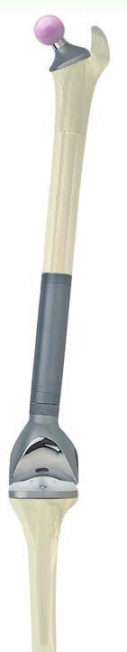
24 37 Preparation of distal femur is complete. 38 The tibial trial stem and trial prosthesis are joined by screwing them together and inserted into the prepared tibia. 39 The femoral trial stem and trial prosthesis are joined by screwing them together and inserted into the prepared femur. 22


25 40 The cylindrical part of the trial prosthesis for connection components ( /00) is inserted in the tibial trial prosthesis. The transverse axle of the femoral trial prosthesis is then inserted in the opened clamp of the connection components. The connection is secured by tightening the knurled screw. 41 By extending, flexing and rotating the treated limb, it is possible to estimate the leg length and degrees of rotation and flexion. In the case of existing tibial or femoral defects, the joint line can be reconstructed by using femoral segments and/or proximal tibial spacers. It is not permissible to combine several segments or spacers one adequate height has to be used. The polyethylene femoral segments and proximal tibial spacers are fixed to the implant with bone cement. The Tilastan spacers are fixed by means of fastening screws included in the supply (see sterile packaging for description). 23


.")
 firmly onto the")

26 Assembling the Tibial Implant Components The tibial stems are fixed by means of a tapered connection on the tibial component. It should be ensured that the flanges of the prosthetic stems are inserted into the intended slots. The stem is then fixed to the tibial component with screw assembly. Screws are only to be tightened hand-tight. After the underside of the tibial prosthetic component has been coated with a thin layer of bone cement, the prosthesis is inserted into the tibia with the impactor ( /02). By tightening the locking screw (2) located in the taper (3) of the tibial respectively femoral component its pointed tip presses the stem (1) firmly onto the taper. A counter screw (4) secures the stem locking screw against loosening. The screw fixation is performed medially. Screws are only to be tightened hand-tight. 2 3 Counter Screw Important Information: The locking srew (optionally pre-assembled), the counter screw and one replacement screw each are included separately in the packaging


.")


 46 + 47 After the")

 and the lock is")
27 The temporary cementing screw remains in place until the bone cement has set, thus protecting the thread of the prosthesis (excess bone cement is removed). After the cement has set, the screw is removed with the screwdriver ( /01). The prosthetic component coated with bone cement is placed on the femur with light blows of the impactor ( /01) until it fits snugly. (excess bone cement is removed). Trial Screw (fl attened screw head) After the bone cement has set, the transport lock is removed. The screw joint is loosened with the screwdriver ( /01) and the lock is withdrawn with slight rotation. The PE plateau is placed on the tibial metal carrier with the insertion instrument ( /03). 25


 Caution!")


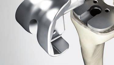
28 The connector with the rotation axle is placed on the tibial component, and the PE plateau is then inserted and screwed on. To obtain better access to the screw, the connector is slightly rotated. Self-locking Screw (round screw head) Caution! The self-locking fixation screw may only be used during the final assembly of the plateau. Loosening the fixation screw destroys the screw retention system in the polyethylene plateau, and a new plateau must then be inserted. 50 The connecting component is inserted into the intracondylar slot of the femoral component and the axle lock is removed. Move the component slightly until the axle is heard to click into the joint box. 26


29 Check the position of the holes. When the prosthetic axle is fully expanded, the holes are at the level of the arrow marks. If this is not the case, the connecting and separating forceps ( /01) can be used to adjust the holes at the correct level Following expansion of the prosthetic axle, this must be locked by means of a screw. The screw (enclosed in the pack) is inserted and hand tightened in the connector using the hex screwdriver ( /16) Situation following assembly. 27


 and the PE plateau")
30 If use of a hinged knee version is planned, the screws in the tibial plateau must first be removed with the hex screwdriver ( /16). The connector with hinge axle is placed on the tibial component. The connector is then screwed in place using the hex screwdriver ( /01) and the PE plateau is inserted. 28


31 Assembling the Tibial Implant Components Connecting the components and loosening the lock are performed as in the rotation knee version. Driving the plateau fixation screw. 59 Locking the axle by means of a screw. 29

.")


32 Proximal Tibial Replacement 60 Resection of the proximal tibia at the planned level. 61 Mount the awl in the planned length (100, 130 or 160 mm) in the handle ( /00). When un-cemented modular stems are used, ream with an increasing diameter until the awl makes cortical contact over a continuous distance of approx. 50 mm. The uncemented implant that will be used must correspond in length and diameter to the last awl used. For cemented modular stems, the awl should be at least 2 mm larger than the planned stem diameter. Important notes: Using the awls with a drive motor is not permitted. 30


.")
33 62 When use of a recess ring is planned as a flat attachment of the extramedullary part of the implant to the bone, the awl is inserted deeply into the medullary canal until the cutting edges of the awl are at the same level as the resection level. The handle is removed and connected to the reamer ( /30). 63 The resection surface is reamed flat with the reamer, which is guided by the shaft of the awl. 31


34 64 The reamer and awl are removed. 65 The trial stem and trial prosthesis for proximal tibial replacement are joined by screwing them together and inserted into the prepared tibia. 66 The femoral trial stem and trial prosthesis are joined by thread attachment and inserted into the prepared femur. 32


35 67 The femoral trial prosthesis is assembled, inserted and connected as described under Standard preparation of the femur. By extending, flexing and rotating the treated limb, it is possible to estimate the leg length and degrees of rotation and flexion. Distal Femoral Replacement 68 Depending on the indication, the distal femoral replacement can be extended in 10 mm increments after an initial further resection of 30 mm. Bone preparation is performed as described above. 33
 are assembled between the trial stem and trial prosthesis for distal femoral replacement.")


 70 Resection of the bone at the desired site.")
36 69 In this situation, trial prostheses for stem elements (e.g /00) are assembled between the trial stem and trial prosthesis for distal femoral replacement. Depending on the resection length, different trial prostheses for stem elements can be combined together to represent the desired leg length. When selecting the suitable size for the trial prosthesis (distal femur replacement) and the final implant, the maximum size of the implant component should be taken. Hereby, it is possible to avoid soft tissue atrophies which could complicate further revisions. Bone Preparation without using a recess ring (optional procedure) 70 Resection of the bone at the desired site. The cutting edges of the awl are then inserted in the medullary canal 10 mm deeper than the resection level and the resection level is prepared with the step reamer ( /18 up to a stem diameter of 18 mm, /24 for 19 mm or more). 71 Assembling the selected trial prostheses. 34
 72 The two guide rods (16-3235/00) are screwed")
 through the two holes of")
 is placed on the")


37 Bone Preparation without using a recess ring (optional procedure) 72 The two guide rods ( /00) are screwed into the adapter ring ( /00) and placed from proximal to distal (vice versa in the tibia) through the two holes of the trial joint component. 73 The saw guide for notching ( /00) is placed on the adapter ring in such a way that the notch and spring engage. 74 The trial prosthesis is inserted into the bone as far as its final position. It is essential to ensure correct rotational alignment of the trial prosthesis. The adapter ring must sit flush on the resection surface. 35


38 75 The saw guide for notching is fixed with two wire pins. The trial implant with the adapter ring is then removed. 76 Preparing the notches with the oscillating saw. 77 Prepared notches. 36


.")


.")


39 Push-through Prosthesis Prior to implantation of the push-through stems for total femoral replacement, the medullary cavity is reamed with ball reamers or flexible medullary reamers approx. 1 2 mm larger than the diameter of the selected prosthesis (available in 14 mm or 16 mm). The length of the push-through prosthesis and the level of the femoral shaft resection should be chosen so that the sprocket for accepting the neck components is approximately mm above the lesser trochanter. If necessary to adjust the length, this can be done by means of the proximal spacers ( /10-20) The push-through stems can be inserted direcly with the femoral components, as directly in example 4 in the brochure Implants and Instruments, or, as shown here, in combination with shaft elements. Fixation at the resection site is again optional (recess ring or notches). The proximal part of the push-through prosthesis after implantation. 37


 using")
 the implant bed")


40 The tubular reamer ( /01) is used to prepare the metaphyseal medullary cavity, in the selected length after connecting drill guide with stop as illustrated. The drill guide with stop acts as a drill stop and at the same time prevents damage to the push-through prosthesis. Screw on the drill guide with stop ( or /90) using the cross-slot screwdriver ( /00) With the tubular reamer ( /01) the implant bed is prepared for the neck component. The selected neck component is then pushed on the sprocket of the push-through stem, the desired anteversion is obtained and the neck component is fixed with the trial fixation screw ( /38 or /58) using the hex screwdriver ( /02). 38


 10 mm 30 mm 20 mm 20")
 Spacers")
41 86 Colored plastic trial heads ( /01-04, /01-04, /01-04) in diameters 28, 32 or 36 mm and neck lengths short, medium, long and extra long are used for trial reduction. If leg lengthening is necessary, spacers can be used in the illustrated combination when using neck components with a length of 65 mm. Trial spacers ( /10 or /20) are available for trial reduction. 87 Fixation screws (trial + implant) Spacers (trial + implant) 10 mm 30 mm 20 mm 20 mm 58 mm 38 mm 20 mm 10 mm 88 Neck components (trial + implant) Spacers (trial + implant) 30 mm 20 mm 10 mm 65 mm 35 mm 20 mm 10 mm 39


 is then passed over")


.")


 as described in example 6 of the brochure")
42 After final alignment of the neck component, the guide rod with ruler is screwed into the upper part of the push-through stem through the shoulder of the neck component using the hex screwdriver ( /02). The go/no go guide ( ) is then passed over the guide rod as far as the shoulder, as illustrated. The toothing of the neck component and push-through stem then engage correctly when the edge of the go/no go guide is exactly on one mark of the lines at the ruler (0, 10, 20 or 30) Expansion bolts ( /38 or /58) are used for finally joining the neck component to the pushthrough stems. A precise description of use of the bolts and their instruments is given on page 43. With loss of the proximal femur, the push-through stems can be combined with the neck elements (solid) as described in example 6 of the brochure MEGASYSTEM-C Implants and Instruments. The correct position of the implant and fixation with expansion bolts are checked as described previously. 40


.")

43 Proximal Femoral Replacement Resection of the proximal femur at the planned site and preparation of the medullary cavity to accept the selected stem model as described under Proximal tibial replacement. After implantation of the modular stem, attachment of stem elements is optional Attachment of the coupling component for proximal femur replacement, short or long ( /28 or /30). Attachment of the neck (solid). Fix the implant as described under push-through prosthesis. 41


44 Interposition Implant Resection of the femoral diaphysis at the planed sites and preparation of the medullary cavity to accept the selected modular stems as described under Proximal tibial replacement. Situation after implantation of the interposition components as described in example 8 of the brochure MEGASYSTEM-C Implants and Instruments. The two interposition components are joined with the aid of the cross-slot screwdriver ( /00) and enclosed screws. 42

 Using the screwdriver (L), the expansion")
 with plastic sleeve (N) is attached to the taper of the neck segment and fastened by operating the lever (R).")


45 Instruction of Expansions Bolts L O M N Q P O R The stem, any spacers and the neck segment are connected with either a 41 mm or 61 mm expansion bolt (M), depending on the neck segment length and the number of spacers. The expansion bolt securely fixes the MP neck segments to the modular MP stem. Two bolt lengths are available: 41 and 61 mm The 41 mm bolt is used if no spacer or one 10 mm spacer is used. The 61 mm bolt is used if one 20 mm spacer is used or a 10 mm spacer is used in conjunction with a 20 mm spacer (overall height: 30 mm) Using the screwdriver (L), the expansion bolt is screwed in as far as stop and lightly tightened. Then the holder (O) with plastic sleeve (N) is attached to the taper of the neck segment and fastened by operating the lever (R). Using the torque wrench (P) the inserted expansion bolt is tightened twice as far as short mark 1 on the scale. While tightening, it is important to keep a firm grip on both the holder and the torque wrench to ensure that the neck segment remains in situ without rotation. Tightening the expansion bolt as far as short mark 1 on the scale corresponds to a tightening torque of 14.5 to 16.3 Nm. The resulting elastic expansion of the bolt effectively fastens the connection. The trial head (Q) is placed on the taper of the neck segment and a final trial reduction is performed to check ante-version. Caution! LINK implants and expansion bolts are solely designed for single use. They must not be reused. The torque wrench is supplied with a calibration certificate. The torque wrench is to be sent to WALDEMAR LINK GmbH & Co. KG for re-calibration after 250 applications. The torque wrench must never be used to undo screw connections, since this could damage it. Plasticsleeve integrity must be checked prior to use. 43


46 Additional Information MEGASYSTEM-C Tumor and Revisions Surgery Implants & Instruments MEGASYSTEM-C Tumor and Revision System, Assembling Instruments Endo-Model SL Rotational and Hinge Knee Prosthesis System 733_Implants & Instruments 733_Surgical Technique All catalogs available on request. For more information please register for our LINK Media Library (linkorthopaedics.com) 44
47 Important Information Please note the following regarding the use of our implants: 1. Choosing the right implant is very important. The size and shape of the human bone determines the size and shape of the implant and also limits the load capacity. Implants are not designed to withstand unlimited physical stress. Demands should not exceed normal functional loads. 2. Correct handling of the implant is very important. Under no circumstances should the shape of a finished implant be altered, as this shortens its life span. Our implants must not be combined with implants from other manufacturers. The instruments indicated in the Surgical Technique must be used to ensure safe implantation of the components. 3. Implants must not be reused. Implants are supplied sterile and are intended for single use only. Used implants must not be used again. 4. After-treatment is also very important. The patient must be informed of the limitations of the implant. The load capacity of an implant cannot compare with that of healthy bone! 5. Unless otherwise indicated, implants are supplied in sterile packaging. Note the following conditions for storage of packaged implants: Avoid extreme or sudden changes in temperature. Sterile implants in their original, intact protective packaging may be stored in permanent buildings up until the Use by date indicated on the packaging. They must not be exposed to frost, dampness or direct sunlight, or mechanical damage. Implants may be stored in their original packaging for up to 5 years after the date of manufacture. The Use by date is indicated on the product label. Do not use an implant if the packaging is damaged. 6. Traceability is important. Please use the documentation stickers provided to ensure traceability. 7. Further information on the material composition is available on request from the manufacturer. Follow the instructions for use! Waldemar Link GmbH & Co. KG, Hamburg, Germany All content in this catalog, including text, pictures and data, is protected by law. Every instance of use, whether in part or in whole and which is not permitted by law, is subject to our prior consent. In particular, this applies to the reproduction, editing, translation, publishing, saving, processing, or passing on of content stored in databases or other electronic media and systems, in any manner or form. The information in the catalogs is solely intended to describe the products and does not constitute a guarantee. The Surgical Technique described has been written to the best of our knowledge and belief, but it does not relieve the surgeon of his/her responsibility to duly consider the particularities of each individual case.
48 LINK 909_Mega-C_OP_en_ _006 Waldemar Link GmbH & Co. KG Barkhausenweg Hamburg, Germany Phone
Endo-Model SL. Rotational and Hinge Knee Prosthesis System. Implants & Instruments
 Endo-Model SL Rotational and Hinge Knee Prosthesis System Implants & Instruments Presented by: Waldemar Link GmbH & Co. KG Barkhausenweg 10 22339 Hamburg, Germany Tel.: +49 40 53995-0 info@linkhh.de www.linkorthopaedics.com
Lubinus Classic Plus Hip Prosthesis System
 Lubinus Classic Plus Hip Prosthesis System Presented by: Waldemar Link GmbH & Co. KG Barkhausenweg 10 22339 Hamburg, Germany P.O. Box 63 05 52 22315 Hamburg, Germany Tel.: +49 40 53995-0 Fax: +49 40 5386929
ANATOMIC SURGICAL TECHNIQUE. 5 in 1. Conventional instrumentation 07/11/2013
 ANATOMIC SURGICAL TECHNIQUE 5 in 1 Conventional instrumentation PRO.GB.933/1.0 Octobre 2013 2 Tibial step 3 Intramedullary technique - Based on the preoperative plan, drill the medullary canal with the
TRK REVISION KNEE Surgical Technique
 1 TRK REVISION KNEE Surgical Technique 1. 2. 3. 4. 5. 6. 7. 8. 9. 10. INTERCONDYLAR RESECTION...... page FEMORAL STEM...... page NON CEMENTED FEMORAL STEM...... page TRIAL FEMORAL COMPONENTS...... page
Distal Cut First Femoral Preparation
 Surgical Technique Distal Cut First Femoral Preparation Primary Total Knee Arthroplasty LEGION Total Knee System Femoral preparation Contents Introduction...3 DCF femoral highlights...4 Preoperative planning...6
BiMobile Dual Mobility System Cementless & Cemented. Surgical Technique
 BiMobile Dual Mobility System Cementless & Cemented Surgical Technique Presented by: Waldemar Link GmbH & Co. KG Barkhausenweg 10 22339 Hamburg Germany Phone +49 40 53995-0 info@linkhh.de www.linkorthopaedics.com
Lubinus Classic Plus Hip Prosthesis System
 Lubinus Classic Plus Hip Prosthesis System Presented by: WALDEMAR LINK GmbH & Co. KG Barkhausenweg 10 22339 Hamburg, Germany P. O. Box 63 05 52 22315 Hamburg, Germany Tel.: +49 40 53995-0 Fax: +49 40 5386929
OPERATIVE TECHNIQUE SKS Total Knee Replacement
 OPERATIVE TECHNIQUE SKS Total Knee Replacement Femoral preparation A40577 1 2 5 1: Alignment rod A30049 + A30124 2: Centromedullary rod A40224 4: T-handle A40232 6: Femoral measuring device A40411 + A40414
Zimmer NexGen MIS Tibial Component. Cemented Surgical Technique IMAGE TO COME
 Zimmer NexGen MIS Tibial Component Cemented Surgical Technique IMAGE TO COME Zimmer NexGen MIS Tibial Component Cemented Surgical Technique 1 Zimmer NexGen MIS Tibial Component Cemented Surgical Technique
Resurfacing Distal Femur. Orthopaedic Salvage System
 Resurfacing Distal Femur Orthopaedic Salvage System Primary Arthroplasty OSS 3cm Resurfacing Distal Femur Distal Femoral Resection Drill and ream the distal femur in the following sequence: (Figure 1)
Orthopedic Bone Nail System - Distal Femoral Nail Surgical Technique Manual
 Orthopedic Bone Nail System - Distal Femoral Nail Surgical Technique Manual Note: The surgical procedures should be performed under the guidance of qualified skilled orthopedic surgeons, and this surgical
U2 PSA. Revision Knee. Surgical Protocol
 U2 PSA TM Revision Knee Surgical Protocol Table of Contents 1 Component Removal... 1 2 Tibial Preparation... 1 2.1 Tibial Canal Preparation... 1 2.2 Proximal Tibial Resection... 2 2.3 Non Offset Tibial
Endo-Model Unicondylar Sled Prosthesis. with MITUS Instrument Set. Implants & Instruments
 Endo-Model Unicondylar Sled Prosthesis with MITUS Instrument Set Implants & Presented by: Waldemar Link GmbH & Co. KG Barkhausenweg 10 22339 Hamburg, Germany P.O. Box 63 05 52 22315 Hamburg, Germany Tel.:
Zimmer NexGen Trabecular Metal Tibial Tray
 Zimmer NexGen Trabecular Metal Tibial Tray Surgical Technique Zimmer NexGen Trabecular Metal Tibial Tray Surgical Technique Give Bone A Solid Hold Zimmer NexGen Trabecular Metal Tibial Tray Surgical Technique
operative technique Kent Hip
 operative technique Kent Hip The Kent Hip Operative Technique The Kent Hip was developed by Mr Cliff Stossel, FRCS in Maidstone, Kent, UK and first implanted in 1986. It was designed to deal with problems
MRH Knee System Modular Peg Baseplate Surgical Protocol
 MRH Knee System Modular Peg Baseplate Surgical Protocol Using Monogram IM Revision Instruments 4 N 4 N Modular Rotating Hinge Knee System Using Monogram IM Revision Instruments Mr C R Howie FRCS Consultant
Reconstruction Prosthesis cementless & cementable
 MP Reconstruction Prosthesis cementless & cementable Surgical Technique Presented by: WALDEMAR LINK GmbH & Co. KG Barkhausenweg 10. 22339 Hamburg, Germany P.O. Box 63 05 52. 22315 Hamburg, Germany Tel.:
MIS Cemented Tibial Component
 MIS Cemented Tibial Component NexGen Complete Knee Solution Surgical Technique Table of Contents Surgical Exposure... 2 Finish the Tibia... 2 Position Based on Anatomic Landmarks... 3 Lateral Posterior
THE NATURAL FIT. Surgical Technique. Hip Knee Spine Navigation
 THE NATURAL FIT Surgical Technique Hip Knee Spine Navigation MiniMAX Surgical Technique Hip Knee Spine Navigation INTRODUCTION The MiniMAX TM is a cementless anatomic stem available in 9 right sizes and
Proven Gen-Flex Revision Knee System. Surgical Protocol
 Proven Gen-Flex Revision Knee System Surgical Protocol Proven Gen-Flex Revision Knee System Surgeon Design Team The Proven Gen-Flex Revision Knee System Instrumentation and Surgical Protocol were developed
OPERATING MANUAL AND TECHNIQUE GUIDE FOR TITANIUM FEMORAL AND TIBIAL NAILING SYSTEMS
 OPERATING MANUAL AND TECHNIQUE GUIDE FOR TITANIUM FEMORAL AND TIBIAL NAILING SYSTEMS ORTHO-MEDICAL GMBH TITANIUM FEMORAL NAIL OPERATIVE TECHNIQUE Introduction: Why a new type of femoral nail? The latest
Arcos Modular Femoral Revision System. Broach and Calcar Proximal Bodies Surgical Technique
 Arcos Modular Femoral Revision System Broach and Calcar Proximal Bodies Surgical Technique Table of Contents Pre-operative Planning...2 Patient Positioning and Surgical Approach...2 Removal of a Cemented
The Modular Knee System GenuX MK Revision Knee
 The Modular Knee System GenuX MK Revision Knee Surgical Technique GenuX MK Revision Knee Surgical Technique Table of content Preoperative Planning...5 System Overview...6 Compatibility Matrix...7 Surgical
SCORE Revision. Revision Total Knee Arthroplasty Cemented. Surgical Technique With Conventional Instrumentation Primary cases
 SCORE Revision Revision Total Knee Arthroplasty Cemented Surgical Technique With Conventional Instrumentation Primary cases SCORE REVISION FOR PRIMARY CASES The SCORE Revision is a revision total knee
Bone Preservation Stem
 TRI-LOCK Bone Preservation Stem Featuring GRIPTION Coating Surgical Technique Implant Geometry Extending the TRI-LOCK Stem heritage The original TRI-LOCK Stem was introduced in 1981. This implant was
TOTAL KNEE ARTHROPLASTY SYSTEM
 SURGICAL TECHNIQUE TOTAL KNEE ARTHROPLASTY SYSTEM 90-SRK-700000 B.0 0 Contents 1. Implant Sizing 2. Surgical Technique a. Incision and Exposure b. Distal Femoral Resection c. Tibial Resection d. Femoral
Triathlon Knee System. Universal Baseplate Surgical Protocol
 Triathlon Knee System Universal Baseplate Surgical Protocol Table of Contents Acknowledgments..........................................................2 Introduction...............................................................2
Triathlon Knee System Universal Baseplate Surgical Protocol
 Triathlon Knee System Universal Baseplate Surgical Protocol Triathlon Knee System Universal Baseplate Surgical Protocol Table of Contents Acknowledgments... 2 Introduction... 2 Assembly Instructions...
Extramedullary Tibial Preparation
 Surgical Technique Extramedullary Tibial Preparation Primary Total Knee Arthroplasty LEGION Total Knee System Extramedullary tibial preparation Contents Introduction...2 EM tibial highlights...3 Preoperative
THE P.F.C. SIGMA FEMORAL ADAPTER. Surgical Technique
 THE P.F.C. SIGMA FEMORAL ADAPTER Surgical Technique Contents P.F.C. Sigma Femoral Adapter and Revision Knee Surgery Introduction 2 Preoperative Planning 2 Overview 3 Surgical Technique Preparation of the
BIOTECH FUTURE KNEE Minimal Invasive (and classic) Surgical Technique
 Surgical Technique") BIOTECH FUTURE KNEE Minimal Invasive (and classic) Surgical Technique Page No. Product description 2. Pre-operational planning 3. 1st step Femoral resection 4. P/S Femoral component 7. 2nd step Proximal
BIOTECH FUTURE KNEE Minimal Invasive (and classic) Surgical Technique Page No. Product description 2. Pre-operational planning 3. 1st step Femoral resection 4. P/S Femoral component 7. 2nd step Proximal
GENERIC, LOGIC, INTEGRALE TO.H.GB.011/1.0
 Surgical technique mechanical instrumentation GENERIC, LOGIC, INTEGRALE TO.H.GB.011/1.0 2 Pre-surgical planning By means of radiological assessment and templates, it is possible to: - determine the position
Cementless Tapered Femoral Stem Surgical technique
 Cementless Tapered Femoral Stem Surgical technique Contents Operative summary 4 Pre-operative planning 5 Femoral neck osteotomy 5 Femoral canal preparation 5 Intra-medullary (IM) reamer 6 Sequential rasping
Surgical Technique. Unisyn Hip System
 Surgical Technique Unisyn Hip System INDICATIONS AND USAGE Significantly impaired joints resulting from rheumatoid, osteo, and post-traumatic arthritis. Revision of failed femoral head replacement, hip
Intramedullary Tibial Preparation
 Surgical Technique Intramedullary Tibial Preparation Primary Total Knee Arthroplasty LEGION Total Knee System Intramedullary tibial preparation Contents Introduction...2 IM tibial highlights...3 Preoperative
LPS SYSTEM POCKET GUIDE
 LPS SYSTEM POCKET GUIDE Implants Procedural Uses Instruments & Trials L P S Limb Preservation System L P S Limb Preservation System The purpose of this document is to review the LPS (Limb Preservation
VerSys LD/Fx Cemented and Press-Fit Hip Prostheses. Surgical Technique IMAGE TO COME. Versatile solutions for total and partial hip replacement
 VerSys LD/Fx Cemented and Press-Fit Hip Prostheses Surgical Technique IMAGE TO COME Versatile solutions for total and partial hip replacement VerSys LD/Fx Cemented and Press-Fit Hip Prostheses VerSys
Surgical Technique. Hinge Disassembly and Rebuild Technique
 Surgical Technique Hinge Disassembly and Rebuild Technique Revision Knee Arthroplasty Surgical Technique LEGION HK Hinge Knee System Introduction The LEGION HK Hinge Knee System has been designed as an
Triathlon TS Knee System. Surgical Protocol
 Triathlon TS Knee System Surgical Protocol Triathlon TS Knee System Surgical Protocol Table of Contents Acknowledgments..........................................................2 Exposure...................................................................4
Clinical Evaluation Surgical Technique
 Clinical Evaluation Surgical Technique Table of Contents EMPERION Specifications 3 EMPERION Surgical Technique 9 EMPERION Catalog 18 Nota Bene: This technique description herein is made available to the
Total Knee Original System Primary Surgical Technique
 Surgical Procedure Total Knee Original System Primary Surgical Technique Where as a total hip replacement is primarily a bony operation, a total knee replacement is primarily a soft tissue operation. Excellent
TM HUMELOCK II. Cemented. Hemi / Trauma. Total / Primary SURGICAL TECHNIQUE
 TM HUMELOCK II Cemented Hemi / Trauma SURGICAL TECHNIQUE Total / Primary CONTENTS - Surgical technique Humerus : Degenerative...page 0 - Surgical technique Glenoid...page 0 - Surgical technique Humerus
SURGICAL TECHNIQUE. Alpine Cementless Hip Stem
 SURGICAL TECHNIQUE Alpine Cementless Hip Stem The following technique is a general guide for the instrumentation of the Alpine Cementless Hip Stem. It is expected that the surgeon is already familiar with
Revolution. Unicompartmental Knee System
 Revolution Unicompartmental Knee System While Total Knee Arthroplasty (TKA) is one of the most predictable procedures in orthopedic surgery, many patients undergoing TKA are in fact excellent candidates
The ACL-PCL Substituting Knee. BioFoam Tibial Bases. Surgical Technique For Cementless Tibial Fixation
 The CL-PCL Substituting Knee BioFoam Surgical Technique For Cementless Tibial Fixation Surgical techniques and instrument recommendations were provided by: Michael nderson, MD Milwaukee, WI G. Lynn Rasmussen,
OSS Modular Arthrodesis System. Assembly Guide
 OSS Modular Arthrodesis System Assembly Guide One Surgeon. One Patient. Over 1 million times per year, Biomet helps one surgeon provide personalized care to one patient. The science and art of medical
NeoGen Tibia Nail System
 NeoGen Tibia Nail System LESS IS MORE TE-2070-03 Surgical Technique BLE OF CONTENT Preface Surgical Technique Appendix Products Information Patient Preparation Entry Portal Fracture Reduction Canal Preparation
Cementless Tapered Femoral Stem Surgical technique
 Cementless Tapered Femoral Stem Surgical technique Contents Operative summary 4 Pre-operative planning 5 Femoral neck osteotomy 5 Femoral canal preparation 5 Intra-medullary (IM) reamer 6 Sequential rasping
Surgical procedure. METS Modular Proximal Femur
 Surgical procedure METS Modular Proximal Femur Surgical Procedure Contents 1.0 2.0 3.0 4.0 5.0 Device information 2 3 1.1 Product overview 1.2 Indications 1.3 Absolute contra-indications 1.4 Relative
LCP Medial Distal Tibia Plate, without Tab. The Low Profile Anatomic Fixation System with Angular Stability and Optimal Screw Orientation.
 LCP Medial Distal Tibia Plate, without Tab. The Low Profile Anatomic Fixation System with Angular Stability and Optimal Screw Orientation. Technique Guide LCP Small Fragment System Table of Contents Introduction
The Titanium Tibial Nail System
 The Titanium Tibial Nail System Solid Tibial Nails (UTN) and Cannulated Tibial Nails (CTN) Surgical Technique This publication is not intended for distribution in the USA. Instruments and implants approved
Encina Taper Stem. Stinson Orthopedics Inc. 303 Twin Dolphin Drive, Suite 600 Redwood City, CA
 Stinson Orthopedics Inc. 303 Twin Dolphin Drive, Suite 600 Redwood City, CA 94065 info@stinsonortho.com www.stinsonortho.com Table of Contents Introduction 3 Features 4 Surgical Technique 5 Preoperative
CAUTION: Ceramic liners are not approved for use in the United States.
 Total Hip Prostheses, Self-Centering Hip Prostheses and Hemi-Hip Prostheses IMPORTANT: This essential product information sheet does not include all of the information necessary for selection and use of
SURGICAL TECHNIQUE CEMENTED & PRESS-FIT UNIFIED INSTRUMENTATION INTRAOPERATIVE FLEXIBILITY PROVEN BIOMECHANICS
 SURGICAL TECHNIQUE CEMENTED & PRESS-FIT UNIFIED INSTRUMENTATION INTRAOPERATIVE FLEXIBILITY PROVEN BIOMECHANICS INTRODUCTION The Summit Tapered Hip System s comprehensive set of implants and instruments
Patella Planing System
 REFERENCE GUIDE AND SURGICAL TECHNIQUE Patella Planing System SPECIALIST INSTRUMENTS AN ONLAY PATELLA PREPARATION SYSTEM TECHNIQUE FOR PRIMARY PATELLAR RESURFACING The Specialist 2 Patellar Planer System
TITANIUM TIBIAL NAIL SySTEM
 TITANIUM TIBIAL NAIL SySTEM Solid and Cannulated Nails SURGICAL TEChNIqUE Table of contents Introduction Indications 2 Preoperative Implant Selection 6 Surgical Technique Instruments for Opening the Tibia
asterloc Surgical Technique HIP SYSTEM UNDERSTANDING TRADITION, MASTERING INNOVATION Hip Knee Spine Navigation
 asterloc HIP SYSTEM UNDERSTANDING TRADITION, MASTERING INNOVATION Surgical Technique Hip Knee Spine Navigation Masterloc Surgical Technique Hip Knee Spine Navigation INTRODUCTION This document describes
ANTERIOR REFERENCE NEXGEN COMPLETE KNEE SOLUTION. Multi-Reference 4-in-1 Femoral Instrumentation Anterior Reference Surgical Technique
 ANTERIOR REFERENCE NEXGEN COMPLETE KNEE SOLUTION Multi-Reference 4-in-1 Femoral Instrumentation Anterior Reference Surgical Technique For NexGen Cruciate Retaining & Legacy Posterior Stabilized Knees INTRODUCTION
Preoperative Planning. The primary objectives of preoperative planning are to:
 Preoperative Planning The primary objectives of preoperative planning are to: - Determine preoperative leg length discrepancy. - Assess acetabular component size and placement. - Determine femoral component
Arcos Interlocking Distal Stem. Surgical Technique Addendum to the Arcos Modular Femoral Revision System
 Arcos Interlocking Distal Stem Surgical Technique Addendum to the Arcos Modular Femoral Revision System One Surgeon. One Patient. Over 1 million times per year, Biomet helps one surgeon provide personalized
3.5 MM VA-LCP PROXIMAL TIBIA PLATE SYSTEM
 3.5 MM VA-LCP PROXIMAL TIBIA PLATE SYSTEM Part of the DePuy Synthes Variable Angle Periarticular Plating System SURGICAL TECHNIQUE TABLE OF CONTENTS INTRODUCTION 3.5 mm VA-LCP Proximal Tibial Plate 2 AO
Zimmer NexGen RH Knee Primary/Revision. Surgical Technique
 Zimmer NexGen Primary/Revision Surgical Technique Zimmer NexGen Primary/Revision Surgical Technique INTRO Introduction The NexGen Rotating Hinge Knee () is designed for revision, difficult primary, and
ELEOS Limb Salvage System
 ELEOS Limb Salvage System Surgical Technique Total Femoral Replacement The ELEOS Limb Salvage System offers options for patients with significant bone loss due to cancer, trauma, or previous surgical procedures.
UNDERSTANDING TRADITION, MASTERING INNOVATION. Surgical Technique
 UNDERSTANDING TRADITION, MASTERING INNOVATION Surgical Technique Joint Spine Sports Med MasterLoc Surgical Technique Joint Spine Sports Med INTRODUCTION This document describes the Surgical Technique for
SP-CL PoroLink Anatomically Adapted Cementless Hip System
 SP-CL PoroLink Anatomically Adapted Cementless Hip System Presented by: Waldemar Link GmbH & Co. KG Barkhausenweg 10 22339 Hamburg, Germany Phone +49 40 53995-0 info@linkhh.de www.linkorthopaedics.com
Surgical procedure. METS SMILES Total Knee Replacement
 Surgical procedure METS SMILES Total Knee Replacement Surgical Procedure Contents 1.0 2.0 3.0 4.0 Device information 2 3 1.1 Product overview 1.2 Indications 1.3 Absolute contra-indications 1.4 Relative
Technique Guide. TomoFix Osteotomy System. A comprehensive plating system for stable fixation of osteotomies around the knee.
 Technique Guide TomoFix Osteotomy System. A comprehensive plating system for stable fixation of osteotomies around the knee. Table of Contents Introduction TomoFix Osteotomy System 2 AO Principles 4 Indications
Triathlon Knee System
 Triathlon Knee System Express Instruments Surgical Protocol Posterior Stabilized & Cruciate Retaining TriathlonKneeSystem Express Instruments Surgical Protocol Acknowledgments..........................................................2
Knee. Surgical Protocol
 U2 TM PS CR Knee Surgical Protocol Table of Contents Pre-Operative Planning... Surgical Incision... 1 2 A. Femoral Preparation A.1. Pilot Hole... A.2. Femoral Valgus Angle Confirmation... A.3. Distal
NeoGen Femoral Nail System
 NeoGen Femoral Nail System LESS IS MORE TE-2070-04 Surgical Technique BLE OF CONTENT Preface Standard Femoral Mode Recon Mode Post-Operative Management Appendix Products Information Indication Patient
Constrained Posterior Stabilized (CPS) Surgical Technique
 Surgical Technique") Constrained Posterior Stabilized (CPS) Surgical Technique Constrained Posterior Stabilized (CPS) Surgical Technique INTRO Introduction The Constrained Posterior Stabilized (CPS) articular surfaces can
Constrained Posterior Stabilized (CPS) Surgical Technique Constrained Posterior Stabilized (CPS) Surgical Technique INTRO Introduction The Constrained Posterior Stabilized (CPS) articular surfaces can
Revision Knee System Surgical Technique
 Revision Knee System Surgical Technique Revision Knee System Surgical Technique MUTARS was developed in cooperation with Prof. Dr. W. Winkelmann and Prof. Dr. G. Gosheger, Clinic and Polyclinic for General
NexGen Trabecular Metal Tibial Tray. Surgical Technique
 NexGen Trabecular Metal Tibial Tray Surgical Technique Table of Contents Surgical Technique...2 Resect the Tibia...2 Finish the Tibia...2 Position Based Anatomic Landmarks...3 Position Based on Trial
Efficacy Innovation ABG II. Brochure. Surgical Protocol. Cemented Stem
 Efficacy Innovation ABG II Cemented Stem Brochure Surgical Protocol 2 The ABG Hip System The ABG hip implant range has been progressively extended and enhanced over the past years, harnessing extensive
Surgical Technique.
 Surgical Technique www.biomet.co.uk INTRODUCTION design principals Recent advances in imaging technology have enabled orthopaedic surgeons to extend closed treatment of femoral fractures to include more
LCU Hip System cementless
 LCU Hip System cementless Presented by: Waldemar Link GmbH & Co. KG Barkhausenweg 10 22339 Hamburg Germany Phone +49 40 53995-0 info@linkhh.de www.linkorthopaedics.com Contents LCU Hip System cementless
humerus InSafeLOCK Nail
 humerus InSafeLOCK Nail Introduction Content Humerus InSafeLOCK Nail is an innovative intramedullary nailing system, developed for humerus problems. Humerus fractures have 5-6 % incidence of all bone fractures.
This surgical technique describes how to perform an anatomic total shoulder arthroplasty implanting a short stem.
 INTRODUCTION This surgical technique describes how to perform an anatomic total shoulder arthroplasty implanting a short stem. CAUTION Federal law (USA) restricts this device to sale distribution and use
POSTERIOR REFERENCE NEXGEN COMPLETE KNEE SOLUTION. Multi-Reference 4-in-1 Femoral Instrumentation Posterior Reference Surgical Technique
 POSTERIOR REFERENCE NEXGEN COMPLETE KNEE SOLUTION Multi-Reference 4-in-1 Femoral Instrumentation Posterior Reference Surgical Technique For NexGen Cruciate Retaining & Legacy Posterior Stabilized Knees
AcUMEDr. FoREARM ROD SYSTEM
 AcUMEDr FoREARM ROD SYSTEM FoREARM ROD SYSTEM Since 1988 Acumed has been designing solutions to the demanding situations facing orthopedic surgeons, hospitals and their patients. Our strategy has been
Profix. Total Knee System. As described by
 Profix Total Knee System P R I M A R Y P R O C E D U R E As described by Leo A. Whiteside, M.D. Associate Research Professor Washington University School of Medicine Director, Biomechanical Research Laboratory
3.5 mm Locking Attachment Plate
 For Treatment of Periprosthetic Fractures 3.5 mm Locking Attachment Plate Surgical Technique Table of Contents Introduction 3.5 mm Locking Attachment Plate 2 Indications 4 Surgical Technique Preparation
Zimmer Natural Nail System
 Zimmer Natural Nail System Antegrade Femoral Nail Surgical Technique (Piriformis Fossa & Greater Trochanteric Approaches) Zimmer Natural Nail System Antegrade Femoral Surgical Technique 1 Zimmer Natural
ToeMobile. Surgical Technique. Great Toe Endoprosthesis
 Great Toe Endoprosthesis Surgical Technique Merete Medical, Inc. 99 Purchase Street Rye, N.Y. 10580 Phone: 914 967-1532 Fax: 914-967-1542 E-Mail: service@merete-medical.com www.merete-medical.com - Description
28 Surgical Technique
 Surgical Technique 10 12 14 16 18 20 22 24 28 26 Technique described by James L. Guyton, MD Campbell Clinic Memphis, Tennessee James W. Harkess, MD Campbell Clinic Memphis, Tennessee David G. LaVelle,
OPTIONAL/ADDITIONAL INSTRUMENTS
 20 Elevated 6320-36-22 20 Elevated Rim Liner, 36mm OD x 22mm ID 6320-80-22 20 Elevated Rim Liner, 80mm OD x 22mm ID 6320-42-26 20 Elevated Rim Liner, 42mm OD x 26mm ID 6320-80-26 20 Elevated Rim Liner,
Anatomical Shoulder System
 Anatomical Shoulder System Adjustable. Convertible. Compatible. Anatomical Shoulder System by Zimmer This unique system is like an individually produced prosthesis specifically designed for each patient.
Trilogy Acetabular System
 Trilogy Acetabular System Surgical Technique Versatility in a proven design Trilogy Acetabular System 1 Trilogy Acetabular System Surgical Technique Table of Contents Acetabular Reaming 2 Component Sizing
RECLAIM REVISION SOLUTIONS
 RECLAIM REVISION SOLUTIONS Where Strength and Modularity Connect This publication is not intended for distribution in the USA. SURGICAL TECHNIQUE CONTENTS RECLAIM Modular Revision Hip System SURGICAL TECHNIQUE
The new removable head option. Anatomical Shoulder System
 The new removable head option Anatomical Shoulder System Anatomical Shoulder System by Zimmer This unique system offers the advantages of a custom-made prosthesis. The modularity and design of the Anatomical
Zimmer ITST Intertrochanteric/ Subtrochanteric Fixation System. Abbreviated Surgical Technique
 Zimmer ITST Intertrochanteric/ Subtrochanteric Fixation System Abbreviated Surgical Technique ITST System Abbreviated Surgical Technique Indications The ITST Intramedullary Nail is indicated for use in
For Distal Femur Fractures. 95º Condylar Plate. Quick Reference Chart
 For Distal Femur Fractures 95º Condylar Plate Quick Reference Chart 95 Condylar Plate. Quick reference chart for distal femur fractures. Insert guide wires Fix condylar fragments with 6.5 mm cancellous
Surgical Technique Final Trial Reduction and Component Implantation of
 Surgical Technique Final Trial Reduction and Component Implantation of TC *smith&nephew TC-PLUS PRIMARY Fixed Bearing TC-PLUS PRIMARY Fixed Bearing Final Trial Reduction and Component Implantation of
Sirus Antegrade Femoral Nail System Surgical Technique
 Sirus Antegrade Femoral Nail System Surgical Technique The Cannulated Titanium Nail with Anatomical Shape and Lateral Entry Point Disclaimer This document is intended exclusively for experts in the field,
The information contained in this document is intended for healthcare professionals only.
 The information contained in this document is intended for healthcare professionals only. Orthopaedics GMRS Distal Femoral Surgical Protocol Global Modular Replacement System Acknowledgements Stryker would
Innex Gender Solutions Primary Knee System Standard
 Innex Gender Solutions Primary Knee System Standard Surgical Technique Flexibility through Modularity Disclaimer This document is intended exclusively for physicians and is not intended for laypersons.
Zimmer NexGen Tibial Stem Extension & Augmentation. Surgical Technique IMAGE TO COME. Stem Extensions and Augments
 Zimmer NexGen Tibial Stem Extension & Augmentation Surgical Technique IMAGE TO COME Stem Extensions and Augments Zimmer NexGen Tibial Stem Extension & Augmentation Surgical Technique 1 Zimmer NexGen Tibial
ZMR Over-the-Junction Instruments for Revision Hip Arthroplasty. Surgical Technique IMAGE TO COME
 ZMR Over-the-Junction Instruments for Revision Hip Arthroplasty Surgical Technique IMAGE TO COME ZMR Over-the-Junction Instruments for Revision Hip Arthroplasty Introduction The ZMR Over-the-Junction (OTJ)