SURGICAL TECHNIQUE. Standard Reduction HA Coated Modular. Discover the Difference
|
|
|
- Bryce Fitzgerald
- 5 years ago
- Views:
Transcription


1 SURGICAL TECHNIQUE Standard Reduction HA Coated Modular Discover the Difference
2 TABLE OF CONTENTS REFORM PEDICLE SCREW SYSTEM OVERVIEW 3 TRAY IMAGES & CONTENT 14 SURGICAL TECHNIQUE Preoperative Planning Pedicle Preparation Polyaxial Screw Insertion Modular Screw Insertion Decortication Modular Tulip Attachment Hook Surgical Procedure Reduction Hook Surgical Procedure Rod Insertion Rod Reduction Locking Cap Insertion Final Tightening 43 ADDITIONAL TECHNIQUES Domino Surgical Procedure Lateral Offset Procedure Cross-Connector Surgical Procedure 46 ADVANCED TECHNIQUE 47 Vertebral Body Derotation Procedure 47 Optional Surgical Procedure 48 REFORM KITS 49 CONTRAINDICATIONS, POTENTIAL 50 ADVERSE EFFECTS AND WARNINGS 2


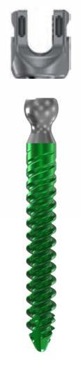
3 REFORM PEDICLE SCREW SYSTEM OVERVIEW Reform is a comprehensive pedicle screw system that is designed to meet the varying requirements of degenerative, trauma and deformity procedures. Reform features a cobalt chrome tulip, a titanium triple lead proximally tapered thread and titanium and cobalt chrome rods to deliver strength, stability and efficiency to all thoracolumbar constructs. Reduction and uniplanar screw options, along with a full line of hooks, dominoes and offsets, complete the system to simplify the procedure and accommodate individual patient anatomy. DEVICE DESCRIPTION The Reform Pedicle Screw System is a top-loading, multiple component, posterior spinal fixation system which consists of pedicle screws, rods, cross-connectors, locking cap screws, hooks, dominoes, and lateral offsets. All of the components are available in a variety of sizes to match more closely the patient s anatomy. All components are made from medical grade stainless steel, cobalt chromium alloys, titanium or titanium alloy described by such standards as ASTM F-138, ASTM F- 1537, ISO , ASTM F-136 or ISO The products are supplied clean and NON-STERILE. The Reform HA Coated Pedicle Screws are supplied STERILE, are made from medical grade titanium or titanium alloy as described by such standards as ASTM F136 or ISO and feature Hydroxyapatite (HA) coating described by such standards as ISO and ASTM INDICATIONS The Reform Pedicle Screw System is intended to provide immobilization and stabilization of spinal segments in skeletally mature patients as an adjunct to fusion in the treatment of the following acute and chronic instabilities or deformities of the thoracic, lumbar, and sacral spine: degenerative spondylolisthesis with objective evidence of neurological impairment, fracture, dislocation, scoliosis, kyphosis, spinal tumor, and failed previous fusion (pseudarthrosis). The Reform Pedicle Screw System is also indicated for pedicle screw fixation for the treatment of severe spondylolisthesis (Grades 3 and 4) of the L5-S1 vertebra in skeletally mature patients receiving fusion by autogenous bone graft having implants attached to the lumbar and sacral spine (L3 to sacrum) with removal of the implants after the attainment of a solid fusion. The Reform Pedicle Screw System is also intended for non-cervical pedicle screw fixation (T1-S1/ilium) for the following indications: degenerative disc disease (as defined by back pain of discogenic origin with degeneration of the disc confirmed by patient history and radiographic studies); trauma (i.e. fracture or dislocation); spinal stenosis; curvatures (i.e. scoliosis, kyphosis; and/or lordosis); spinal tumor; pseudarthrosis; and failed previous fusion. When used for posterior non-cervical pedicle screw fixation in pediatric patients, the Reform Pedicle Screw System is indicated as an adjunct to fusion to treat adolescent idiopathic scoliosis. The Reform Pedicle Screw System is intended to be used with autograft and/or allograft. Pediatric pedicle screw fixation is limited to a posterior approach. Please refer to Instructions For Use (IFU) (LBL-IFU-011) and (LBL-IFU-021; Reform HA Coated Screws) for complete system description, indications and warnings. 3

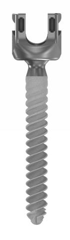
4 REFORM IMPLANT FEATURES Low Profile 12.72mm Footprint x 12.5mm Height T20 Hexalobe Cobalt Chrome Tulip Reduces the Risk of Head Splay with DVR Maneuvers Polyaxial Screws Provide 30 angulation in all planes Proximal Tapered Thread Increases bone/screw interface, enhances pull-out strength Triple Lead Thread Allows for efficient screw delivery Sizing Reform Polyaxial Screws Standard 4.5mm 25-45mm (5mm) 5.5mm 30-50mm (5mm) 6.5mm 30-55mm (5mm) 7.5mm 35-55mm (5mm) 8.5mm 40-60mm (5mm), 70 & 80mm 9.5mm 60, 70 & 80mm 10.5mm* Reform HA Coated Polyaxial Screws Standard 5.5mm 30-50mm (5mm) 6.5mm 30-55mm (5mm) 7.5mm 35-55mm (5mm) 8.5mm 40-60mm (5mm), 70 & 80mm Reform Uniplanar Screws 4.5mm 25-45mm (5mm) 5.5mm 25-50mm (5mm) 6.5mm 30-50mm (5mm) 7.5mm 35-50mm (5mm) Reform Reduction Screws 4.5mm* 5.5mm 30-50mm (5mm) 6.5mm 30-50mm (5mm) 7.5mm 35-55mm (5mm) 8.5mm 40-55mm (5mm) 9.5mm* 10.5mm* Reform Reduction Uniplanar Screws 5.5mm 25-50mm (5mm) 6.5mm 30-45mm (5mm) Modular Tulips Standard Tulip (5.5mm) Reduction Tulip (5.5mm) Modular Screws 4.5mm 5.5mm 6.5mm 7.5mm 8.5mm 9.5mm 25-45mm (5mm) 30-50mm (5mm) 30-55mm (5mm) 35-55mm (5mm) 40-60mm (5mm), 70 & 80mm 60, 70 & 80mm * Special Order Additional sizes available by special order, see pages

 Crosslinks Adjustable 30mm (30-32mm) Part #: 39-CC-0030* 32mm (32-35mm) Part #: 39-CC-0032* 35mm (35-40mm) Part #: 39-CC-0035 40mm (40-48mm) Part #: 39-CC-0040 48mm (48-66mm) Part")
5 Reform Tulip Dimensions 17mm 15.5mm Locking Cap Titanium Square Threaded Locking Cap Geometry Reduces the Risk of Cross-threading Reduces Risk of Head-Splay with DVR Maneuvers Hexalobular T25 Reduces the Incidence of Toggle and Stripping Rods Titanium and Cobalt Chrome Rods Straight Rods 80mm, 100mm, 120mm, 150mm Straight Hex-Ended Rods 200mm, 300mm, 400mm, 500mm Lordotic Curved Rods 35mm-80mm (5mm increments) 90mm-120mm (10mm increments) Crosslinks Adjustable 30mm (30-32mm) Part #: 39-CC-0030* 32mm (32-35mm) Part #: 39-CC-0032* 35mm (35-40mm) Part #: 39-CC mm (40-48mm) Part #: 39-CC mm (48-66mm) Part #: 39-CC mm (66-85mm) Part #: 39-CC-0066 * Not Pictured (available in deformity add-on set) Offset Cam Locking Mechanism 90º Locking Motion Rod-to-Rod Connection 3 of Freedom Linkage provides ±25º of Angulation T20 Hexalobe IMAGE GOES HERE 5.5mm Diameter 5.5mm Diameter 35-40mm 40-48mm 48-66mm 66-85mm 5

 Medium - Part Number: 39-TH-0212 Large - Part Number: 39-TH-0213 Ramped Laminar Small - Part Number: 39-TH-0221 Medium - Part Number: 39-TH-0222 Down Angled Laminar Medium - Part")
6 REFORM DEFORMITY ADD-ON SYSTEM IMPLANTS HOOKS Various Hook options available to accommodate spine anatomy Pedicle Small - Part Number: 39-TH-0101 Medium - Part Number: 39-TH-0102 Large - Part Number: 39-TH-0103 Straight Laminar Small - Narrow - Part Number: 39-TH-0201 Small - Wide - Part Number: 39-TH-0202 Medium - Narrow - Part Number: 39-TH-0203 Medium - Wide - Part Number: 39-TH-0204 Large - Narrow - Part Number: 39-TH-0205 Large - Wide - Part Number: 39-TH-0206 Wide Narrow Ext.-Body Laminar (+4mm) Medium - Part Number: 39-TH-0212 Large - Part Number: 39-TH-0213 Ramped Laminar Small - Part Number: 39-TH-0221 Medium - Part Number: 39-TH-0222 Down Angled Laminar Medium - Part Number: 39-TH-0232 Large - Part Number: 39-TH-0233 Offset Angled Laminar Medium - Right - Part Number: 39-TH-0301 Medium - Left - Part Number: 39-TH-0302 Left Right Angled Hook Medium - Right - Part Number: 39-TH-0401 Medium - Left - Part Number: 39-TH

 Reduction Ramped Laminar Medium - Part Number: 39-TH-0262 Ramped Laminar")


7 REFORM DEFORMITY ADD-ON SYSTEM IMPLANTS REDUCTION HOOKS Straight Laminar Medium - Part Number: 39-TH-0242 Straight Laminar Reduction Hook Ext.-Body Laminar (+4mm) Medium - Part Number: 39-TH-0252 Ext.-Body Laminar (+4mm) Reduction Ramped Laminar Medium - Part Number: 39-TH-0262 Ramped Laminar Reduction Hook Down Angled Laminar Medium - Part Number: 39-TH-0272 Down Angled Laminar Reduction Hook Offset Angled Laminar Medium - Right - Part Number: 39-TH-0351 Medium - Left - Part Number: 39-TH-0352 Offset Angled Laminar Reduction Hook - Right Angled Hook Medium - Right - Part Number: 39-TH-0451 Medium - Left - Part Number: 39-TH-0452 Angled Reduction Hook - Right LATERAL OFFSETS Closed 20mm - Part Number: 39-LO mm - Part Number: 39-LO mm - Part Number: 39-LO mm - Part Number: 39-LO mm Closed Top Loading 20mm Top-Loading 20mm - Part Number: 39-LO mm - Part Number: 39-LO mm - Part Number: 39-LO mm - Part Number: 39-LO mm 40mm 30mm 40mm 50mm 50mm 7


8 REFORM DEFORMITY ADD-ON SYSTEM IMPLANTS DOMINOES Axial Closed-Closed - Part Number: 39-AA-0101 Axial Domino Closed-Closed Parallel Domino Closed-Closed, Wide - Part Number: 39-DA-0101 Closed-Closed, Narrow - Part Number: 39-DA-0102 Closed-Open, Wide - Part Number: 39-DA-0201 Closed-Open, Narrow - Part Number: 39-DA-0202 Open-Open, Wide - Part Number: 39-DA-0301 Open-Open, Narrow - Part Number: 39-DA-0302 Parallel Domino Closed-Closed, Wide Parallel Domino Closed-Closed, Narrow Domino Set Screw Part Number: 39-LS-0200 Parallel Domino Closed-Open, Wide Parallel Domino Closed-Open, Narrow Parallel Domino Open-Open, Wide Parallel Domino Open-Open, Narrow 8

9 Pedicle Screw Tap Undersized Proximally 4.5mm Diameter 4.5mm Tap 5.5mm Diameter 5.5mm Tap 6.5mm Diameter 6.5mm Tap 7.5mm Diameter 7.5mm Tap 8.5mm Diameter 8.5mm Tap 9.5mm Diameter 9.5mm Tap NOTE: 10.5mm available upon request The Reform Pedicle Screw incorporates a proximal taper in its thread design. The difference in the diameters between the screw and tap changes as you move proximally up the thread. When comparing the 5.5mm Tap with a 5.5mm x 45mm Screw the difference in the major diameters between the Tap & Screw is.5mm (.25mm each side) and the difference between the two minor diameters is.25mm (.125mm each side) at the distal portion. At the proximal portion of the Screw thread, the difference between the major diameter of the Screw and the minor diameter of the Tap is 2mm (1mm each side). When comparing a 4.5mm Tap with a 5.5mm x 45 Screw the difference is doubled. The major/major difference is 1mm combined and the minor/minor difference is.5mm at the distal tip. At the proximal portion, the major/minor difference is 4mm. CAUTION: Tapping to size is recommended. If hard bone is encountered, tap to size to prepare the bone for screw insertion. 5.5mm Tap (Grey) 5.5mm x 45mm Screw (Yellow) 4.5mm Tap (Grey) 5.5mm x 45mm Screw (Yellow) 9
10 Pedicle Screwdriver Bone Awl/Bone Punch 3.6mm Diameter 15mm Length Ball Tip Probe (aka Sounder ) 2mm Diameter at Ball Tip 1mm Diameter above Ball Tip 10


11 Reduction Instruments Reduction Tower Quick-Connect feature allows for slip-on insertion over Tulip 25mm of reduction capability 11
12 Reduction Instruments Ratcheting Reduction Gun Simple Finger-Squeeze Mechanism provides easy Tower release, flexing retention arms open 25mm of reduction capability 12
13 Reform Modular Instrumentation Angled Lateral Tulip Clamp Bone Planar Modular Screwdriver Place screwdriver in neutral or reverse position and turn clockwise Turn knurled knob clockwise to tighten collet 13

14 REFORM IMPLANT TRAY 39-BK-01XX Top Level LT-5035 Lordotic Ti Rod, 5.50 x 35mm LT-5040 Lordotic Ti Rod, 5.50 x 40mm LT-5045 Lordotic Ti Rod, 5.50 x 45mm LT-5050 Lordotic Ti Rod, 5.50 x 50mm LT-5055 Lordotic Ti Rod, 5.50 x 55mm LT-5060 Lordotic Ti Rod, 5.50 x 60mm LT-5065 Lordotic Ti Rod, 5.50 x 65mm LT-5070 Lordotic Ti Rod, 5.50 x 70mm LT-5075 Lordotic Ti Rod, 5.50 x 75mm LT-5080 Lordotic Ti Rod, 5.50 x 80mm LT-5090 Lordotic Ti Rod, 5.50 x 90mm LT-5100 Lordotic Ti Rod, 5.50 x 100mm LT-5110 Lordotic Ti Rod, 5.50 x 110mm LT-5120 Lordotic Ti Rod, 5.50 x 120mm LS-0100 Cap Screw / Lock-Screw CC-0035 Cross Connector 35mm CC-0040 Cross Connector 40mm CC-0048 Cross Connector 48mm CC-0066 Cross Connector 66mm ST-5080 Straight Ti Rod, 5.50 x 80mm ST-5100 Straight Ti Rod, 5.50 x 100mm ST-5120 Straight Ti Rod, 5.50 x 120mm ST-5200 Straight Ti Rod, 5.50 x 200mm ST-5400 Straight Ti Rod, 5.50 x 400mm 3 14

15 REFORM IMPLANT TRAY 39-BK-01XX Bottom Level PA x 30mm Polyaxial Pedicle Screw PA x 35mm Polyaxial Pedicle Screw PA x 40mm Polyaxial Pedicle Screw PA x 45mm Polyaxial Pedicle Screw PA x 50mm Polyaxial Pedicle Screw PA x 55mm Polyaxial Pedicle Screw PA x 35mm Polyaxial Pedicle Screw PA x 40mm Polyaxial Pedicle Screw PA x 45mm Polyaxial Pedicle Screw PA x 50mm Polyaxial Pedicle Screw PA x 55mm Polyaxial Pedicle Screw PA x 25mm Polyaxial Pedicle Screw PA x 30mm Polyaxial Pedicle Screw PA x 35mm Polyaxial Pedicle Screw PA x 40mm Polyaxial Pedicle Screw PA x 45mm Polyaxial Pedicle Screw PA x 50mm Polyaxial Pedicle Screw PA x 55mm Polyaxial Pedicle Screw PA x 60mm Polyaxial Pedicle Screw PA x 70mm Polyaxial Pedicle Screw PA x 80mm Polyaxial Pedicle Screw PA x 60mm Polyaxial Pedicle Screw PA x 70mm Polyaxial Pedicle Screw PA x 80mm Polyaxial Pedicle Screw PA x 25mm Polyaxial Pedicle Screw 6 NOTE: Blue Type = Upon Request PA x 30mm Polyaxial Pedicle Screw PA x 35mm Polyaxial Pedicle Screw PA x 40mm Polyaxial Pedicle Screw PA x 45mm Polyaxial Pedicle Screw PA x 50mm Polyaxial Pedicle Screw RP-5530 Reduction Screw 5.5mm x 30mm RP-5535 Reduction Screw 5.5mm x 35mm RP-5540 Reduction Screw 5.5mm x 40mm RP-5545 Reduction Screw 5.5mm x 45mm RP-5550 Reduction Screw 5.5mm x 50mm RP-6530 Reduction Screw 6.5mm x 30mm RP-6535 Reduction Screw 6.5mm x 35mm RP-6540 Reduction Screw 6.5mm x 40mm RP-6545 Reduction Screw 6.5mm x 45mm RP-6550 Reduction Screw 6.5mm x 50mm RP-7535 Reduction Screw 7.5mm x 35mm RP-7540 Reduction Screw 7.5mm x 40mm RP-7545 Reduction Screw 7.5mm x 45mm RP-7550 Reduction Screw 7.5mm x 50mm RP-7555 Reduction Screw 7.5mm x 55mm RP-8540 Reduction Screw 8.5mm x 40mm RP-8545 Reduction Screw 8.5mm x 45mm RP-8550 Reduction Screw 8.5mm x 50mm RP-8555 Reduction Screw 8.5mm x 55mm 2 1) Standard Set included: 5.5, 6.5 & 7.5mm Screws 2) Outlier Caddy (Special Request Only) includes: 4.5, 8.5 & 9.5mm Screws 3) Titanium included in Standard Set Cobalt Chrome (Special Request Only)

16 REFORM ADD-ON IMPLANT TRAY 39-BK-03XX Top Level LS-0100 Cap Screw / Lock-Screw CC-0030 Cross Connector 30mm CC-0035 Cross Connector 35mm DA-0101 Parallel Domino, Closed-Closed, Wide DA-0102 Parallel Domino, Closed-Closed, Narrow DA-0201 Parallel Domino, Closed-Open, Wide DA-0202 Parallel Domino, Closed-Open, Narrow DA-0301 Parallel Domino, Open-Open, Wide DA-0302 Parallel Domino, Open-Open, Narrow AA-0101 Axial Domino, Closed-Closed SC-5300 Straight CoCr Rod, 5.50 x 300mm SC-5500 Straight CoCr Rod, 5.50 x 500mm ST-5300 Straight Ti Rod, 5.50 x 300mm ST-5500 Straight Ti Rod, 5.50 x 500mm LO-0120 Lateral Offset, Closed 20mm LO-0130 Lateral Offset, Closed 30mm LO-0140 Lateral Offset, Closed 40mm LO-0150 Lateral Offset, Closed 50mm LO-0220 Lateral Offset, Top-Loading 20mm LO-0230 Lateral Offset, Top-Loading 30mm LO-0240 Lateral Offset, Top-Loading 40mm LO-0250 Lateral Offset, Top-Loading 50mm LO-0220 Lateral Offset, Top-Loading 20mm LO-0230 Lateral Offset, Top-Loading 30mm LO-0240 Lateral Offset, Top-Loading 40mm LO-0250 Lateral Offset, Top-Loading 50mm 2 NOTE: Blue Type = Upon Request 16
17 REFORM ADD-ON IMPLANT TRAY 39-BK-03XX Bottom Level UP-6530 Uniplanar Screw - 6.5mm x 30mm UP-6535 Uniplanar Screw - 6.5mm x 35mm UP-6540 Uniplanar Screw - 6.5mm x 40mm UP-6545 Uniplanar Screw - 6.5mm x 45mm UP-6550 Uniplanar Screw - 6.5mm x 50mm UP-4525 Uniplanar Screw - 4.5mm x 25mm UP-4530 Uniplanar Screw - 4.5mm x 30mm UP-4535 Uniplanar Screw - 4.5mm x 35mm UP-4540 Uniplanar Screw - 4.5mm x 40mm UP-4545 Uniplanar Screw - 4.5mm x 45mm UP-7535 Uniplanar Screw - 7.5mm x 35mm UP-7540 Uniplanar Screw - 7.5mm x 40mm UP-7545 Uniplanar Screw - 7.5mm x 45mm UP-7550 Uniplanar Screw - 7.5mm x 50mm TH-0242 Straight Laminar Reduction Hook, MD TH-0252 Ext-Body Laminar (+4mm) Reduction Hook, MD TH-0262 Ramped Laminar Reduction Hook, MD TH-0272 Down-Angled Laminar Reduction Hook, MD TH-0351 Offset Angled Reduction Hook, MD, Right TH-0352 Offset Angled Reduction Hook, MD, Left TH-0451 Angled Reduction Hook, MD, Right TH-0452 Angled Reduction Hook, MD, Left UP-5525 Uniplanar Screw - 5.5mm x 25mm UP-5530 Uniplanar Screw - 5.5mm x 30mm UP-5535 Uniplanar Screw - 5.5mm x 35mm UP-5540 Uniplanar Screw - 5.5mm x 40mm 6 NOTE: Blue Type = Upon Request UP-5545 Uniplanar Screw - 5.5mm x 45mm UP-5550 Uniplanar Screw - 5.5mm x 50mm TH-0101 Pedicle Hook, SM TH-0102 Pedicle Hook, MD TH-0103 Pedicle Hook, LG TH-0201 Straight Laminar Hook, SM, Narrow TH-0202 Straight Laminar Hook, SM, Wide TH-0203 Straight Laminar Hook, MD, Narrow TH-0204 Straight Laminar Hook, MD, Wide TH-0205 Straight Laminar Hook, LG, Narrow TH-0206 Straight Laminar Hook, LG, Wide TH-0212 Ext-Body (+4mm) Laminar Hook, MD TH-0213 Ext-Body (+4mm) Laminar Hook, LG TH-0221 Ramped Laminar Hook, SM TH-0222 Ramped Laminar Hook, MD TH-0232 Down-Angled Laminar Hook, MD TH-0233 Down-Angled Laminar, LG TH-0301 Offset Angled Hook, MD, Right TH-0302 Offset Angled Hook, MD, Left TH-0401 Angled Hook, MD, Right TH-0402 Angled Hook, MD, Left RP-5530 Reduction Poly Screw 5.5mm x 30mm RP-5535 Reduction Poly Screw 5.5mm x 35mm 4 Continued on next page 17

18 REFORM ADD-ON IMPLANT TRAY 39-BK-03XX (Cont d..) Bottom Level RP-5540 Reduction Polyaxial Screw 5.5mm x 40mm RP-5545 Reduction Polyaxial Screw 5.5mm x 45mm RP-5550 Reduction Polyaxial Screw 5.5mm x 50mm RP-6530 Reduction Polyaxial Screw 6.5mm x 30mm RP-6535 Reduction Polyaxial Screw 6.5mm x 35mm RP-6540 Reduction Polyaxial Screw 6.5mm x 40mm RP-6545 Reduction Polyaxial Screw 6.5mm x 45mm RP-6550 Reduction Polyaxial Screw 6.5mm x 50mm RP-7535 Reduction Polyaxial Screw 7.5mm x 35mm RP-7540 Reduction Polyaxial Screw 7.5mm x 40mm RP-7545 Reduction Polyaxial Screw 7.5mm x 45mm RP-7550 Reduction Polyaxial Screw 7.5mm x 50mm RP-7555 Reduction Polyaxial Screw 7.5mm x 55mm RP-8540 Reduction Polyaxial Screw 8.5mm x 40mm RP-8545 Reduction Polyaxial Screw 8.5mm x 45mm RP-8550 Reduction Polyaxial Screw 8.5mm x 50mm RP-8555 Reduction Polyaxial Screw 8.5mm x 55mm 2 Reduction Uniplanar Screws (Sent Separately, Not in a Caddy) Part No. Description Qty 39-RU-5525 Reduction Uniplanar Screw Assembly - 5.5mm x 25mm 3 39-RU-5530 Reduction Uniplanar Screw Assembly - 5.5mm x 30mm 3 39-RU-5535 Reduction Uniplanar Screw Assembly - 5.5mm x 35mm 6 39-RU-5540 Reduction Uniplanar Screw Assembly - 5.5mm x 40mm 6 39-RU-5545 Reduction Uniplanar Screw Assembly - 5.5mm x 45mm 6 39-RU-5550 Reduction Uniplanar Screw Assembly - 5.5mm x 50mm 3 39-RU-6530 Reduction Uniplanar Screw Assembly - 6.5mm x 30mm 3 39-RU-6535 Reduction Uniplanar Screw Assembly - 6.5mm x 35mm 6 39-RU-6540 Reduction Uniplanar Screw Assembly - 6.5mm x 40mm 6 39-RU-6545 Reduction Uniplanar Screw Assembly - 6.5mm x 45mm 6 39-RU-6550 Reduction Uniplanar Screw Assembly - 6.5mm x 50mm 3 39-RU-7535 Reduction Uniplanar Screw Assembly - 7.5mm x 35mm 3 39-RU-7540 Reduction Uniplanar Screw Assembly - 7.5mm x 40mm 3 39-RU-7545 Reduction Uniplanar Screw Assembly - 7.5mm x 45mm 3 39-RU-7550 Reduction Uniplanar Screw Assembly - 7.5mm x 50mm 3 NOTE: Blue Type = Upon Request 18
 1 3 39-SP-0555 Pedicle Screw Tap Assembly 5.5mm - (Tap is.5mm undersized) 1 4 39-SP-0565 Pedicle Screw Tap Assembly 6.5mm - (Tap is.5mm undersized) 1 5 39-SP-0575 Pedicle Screw Tap Assembly 7.")
19 REFORM INSTRUMENT TRAY 39-BK-0201 Top Level CH-0004 Ratcheting In-Line "Straight" Handle, 1/4" SQ SP-0545 Pedicle Screw Tap Assembly 4.5mm - (Tap is.5mm undersized) SP-0555 Pedicle Screw Tap Assembly 5.5mm - (Tap is.5mm undersized) SP-0565 Pedicle Screw Tap Assembly 6.5mm - (Tap is.5mm undersized) SP-0575 Pedicle Screw Tap Assembly 7.5mm - (Tap is.5mm undersized) SP-0585 Pedicle Screw Tap Assembly 8.5mm - (Tap is.5mm undersized) SP-0595 Pedicle Screw Tap Assembly 9.5mm - (Tap is.5mm undersized) SP-0011 Ball Tip Sounder Straight SP-0007 Straight Pedicle Probe SP-0005 Duckbill Pedicle Probe SP-0003 Curved Pedicle Probe SP-0001 Bone Awl CH-0003 Ratcheting T-Handle, 1/4" SQ 2 19

20 REFORM INSTRUMENT TRAY 39-BK-0201 Middle Level RD-0010 Flexible Rod Template 200mm RD-0011 Flexible Rod Template 400mm RD-0061 Counter-Torque Wrench RD-0060 Lock-Screw Torque Driver SP-0603 Dual-Side Lock-Screw Driver SP-0815 Rod Pusher 5.5mm SP-0800 Tulip Manipulator SP-0601 Retention Bone-Screw Driver SP-0730 Polyaxial Driver SP-0805 Rod Inserter Forceps 5.5mm SP-0825 Lateral Tulip Holder RD-0070 Extended Tap Removal Tool* CH-0008 Offset Ratcheting Torque Handle 1 *Only included with Reduction Screws 20
 2 4 39-RD-0041 Parallel Compressor 1 5 39-RD-0042 Parallel Distractor 1 6 39-CC-0407 X-Connector Torque Driver 1")
21 REFORM INSTRUMENT TRAY 39-BK-0201 Bottom Level CH-0009 X-Connector Torque Handle CC-0405 X-Connector Rotary Calipers CC-0401 X-Connector Retention Driver (Self-Retaining) RD-0041 Parallel Compressor RD-0042 Parallel Distractor CC-0407 X-Connector Torque Driver 1 21

22 REFORM INSTRUMENT TRAY 39-BK-0202 Top Level RD-0315 T-Handle Reducer RD-0310 Tie Reduction Tower RD-0100 Reduction Gun RD-0602 Lock-Screw Retention Driver SP-0320 Tie Tower Reducer (capable of 25mm reduction) 2 22
 1 3 39-RD-0021 In Situ Rod Bender (Right) 1 4 39-SP-0810 Rod Gripper - 5.")
23 REFORM INSTRUMENT TRAY 39-BK-0202 Bottom Level RD-0001 French Rod Bender - 5.5mm RD-0020 In Situ Rod Bender (Left) RD-0021 In Situ Rod Bender (Right) SP-0810 Rod Gripper - 5.5mm RD-0201 Rod Rocker 1 23

24 REFORM ADD-ON INSTRUMENT TRAY 39-BK-0203 Top Level RD-0316 T-Handle Reducer RD-0348 Tower Bridge Hex Wrench RD-0310 Tie Reduction Tower RD-0320 Tie Tower Reducer RD-0344 Tower Connectors RD-0345 Tower Thumbscrew 8 24
 1 4 39-RD-0031 Coronal Rod Bender (Right) 1 5 39-RD-0346 Tower Bridge, Single 2 6 39-RD-0347 Tower Bridge, Double 2 7 39-SP-0810 Rod Gripper - 5.")
25 REFORM ADD-ON INSTRUMENT TRAY 39-BK-0203 Middle Level RD-0012 Flexible Rod Template - 500mm RD-0032 Coronal Rod Bender Bridge RD-0030 Coronal Rod Bender (Left) RD-0031 Coronal Rod Bender (Right) RD-0346 Tower Bridge, Single RD-0347 Tower Bridge, Double SP-0810 Rod Gripper - 5.5mm 1 25

26 REFORM ADD-ON INSTRUMENT TRAY 39-BK-0203 Bottom Level RD-0550 Superior Hook Holder RD-0570 Domino Inserter/Counter-Torque RD-0050 Rod De-Rotation Hex Wrench RD-0502 Laminar Elevator, Medium RD-0503 Laminar Elevator, Small RD-0500 Pedicular Elevator RD-0560 Hook Pusher 1 26

27 REFORM MODULAR IMPLANT TRAY 39-BK-051X Top Level LT-5035 Lordotic Rod, Ti - ø5.5mm x 35mm LT-5040 Lordotic Rod, Ti - ø5.5mm x 40mm LT-5045 Lordotic Rod, Ti - ø5.5mm x 45mm LT-5050 Lordotic Rod, Ti - ø5.5mm x 50mm LT-5055 Lordotic Rod, Ti - ø5.5mm x 55mm LT-5060 Lordotic Rod, Ti - ø5.5mm x 60mm LT-5065 Lordotic Rod, Ti - ø5.5mm x 65mm LT-5070 Lordotic Rod, Ti - ø5.5mm x 70mm LT-5075 Lordotic Rod, Ti - ø5.5mm x 75mm LT-5080 Lordotic Rod, Ti - ø5.5mm x 80mm LT-5090 Lordotic Rod, Ti - ø5.5mm x 90mm LT-5100 Lordotic Rod, Ti - ø5.5mm x 100mm LT-5110 Lordotic Rod, Ti - ø5.5mm x 110mm LT-5120 Lordotic Rod, Ti - ø5.5mm x 120mm CC mm - Cross-Connector CC mm - Cross-Connector CC mm - Cross-Connector CC mm - Cross-Connector LS-0100 Lock Screw ST-5080 Straight Rod, Ti - ø5.5mm x 80mm ST-5100 Straight Rod, Ti - ø5.5mm x 100mm ST-5120 Straight Rod, Ti - ø5.5mm x 120mm ST-5200 Straight Rod, Ti - ø5.5mm x 200mm ST-5400 Straight Rod, Ti - ø5.5mm x 400mm 3 27

28 REFORM MODULAR IMPLANT TRAY 39-BK-051X Bottom Level 1 39-MS-5530 Bone Screw - ø5.5mm x 30mm MS-5535 Bone Screw - ø5.5mm x 35mm MS-5540 Bone Screw - ø5.5mm x 40mm MS-5545 Bone Screw - ø5.5mm x 45mm MS-5550 Bone Screw - ø5.5mm x 50mm MS-6530 Bone Screw - ø6.5mm x 30mm MS-6535 Bone Screw - ø6.5mm x 35mm MS-6540 Bone Screw - ø6.5mm x 40mm MS-6545 Bone Screw - ø6.5mm x 45mm MS-6550 Bone Screw - ø6.5mm x 50mm MS-6555 Bone Screw - ø6.5mm x 55mm MS-7535 Bone Screw - ø7.5mm x 35mm MS-7540 Bone Screw - ø7.5mm x 40mm MS-7545 Bone Screw - ø7.5mm x 45mm MS-7550 Bone Screw - ø7.5mm x 50mm MT-0301 Standard Tulip Assembly 25 NOTE: Blue Type = Upon Request MT-0302 Reduction Tulip Assembly MS-4525 Bone Screw - ø4.5mm x 25mm MS-4530 Bone Screw - ø4.5mm x 30mm MS-4535 Bone Screw - ø4.5mm x 35mm MS-4540 Bone Screw - ø4.5mm x 40mm MS-4545 Bone Screw - ø4.5mm x 45mm MS-8540 Bone Screw - ø8.5mm x 40mm MS-8545 Bone Screw - ø8.5mm x 45mm MS-8550 Bone Screw - ø8.5mm x 50mm MS-8555 Bone Screw - ø8.5mm x 55mm MS-8560 Bone Screw - ø8.5mm x 60mm MS-8570 Bone Screw - ø8.5mm x 70mm MS-8580 Bone Screw - ø8.5mm x 80mm MS-9560 Bone Screw - ø9.5mm x 60mm MS-9570 Bone Screw - ø9.5mm x 70mm MS-9580 Bone Screw - ø9.5mm x 80mm 2 1) Standard Set included: 5.5, 6.5 & 7.5mm Screws 2) Outlier Caddy (Special Request Only) includes: 4.5, 8.5 & 9.5mm Screws 3) Titanium included in Standard Set Cobalt Chrome (Special Request Only) 28
 1 3 39-SP-0555 Pedicle Screw Tap Assembly 5.5mm - (Tap is.5mm undersized) 1 4 39-SP-0565 Pedicle Screw Tap Assembly 6.5mm - (Tap is.5mm undersized) 1 5 39-SP-0575 Pedicle Screw Tap Assembly 7.")
29 REFORM MODULAR INSTRUMENT TRAY 39-BK-0501 Top Level CH-0004 Ratcheting In-Line "Straight" Handle, 1/4" SQ SP-0545 Pedicle Screw Tap Assembly 4.5mm - (Tap is.5mm undersized) SP-0555 Pedicle Screw Tap Assembly 5.5mm - (Tap is.5mm undersized) SP-0565 Pedicle Screw Tap Assembly 6.5mm - (Tap is.5mm undersized) SP-0575 Pedicle Screw Tap Assembly 7.5mm - (Tap is.5mm undersized) SP-0585 Pedicle Screw Tap Assembly 8.5mm - (Tap is.5mm undersized) SP-0595 Pedicle Screw Tap Assembly 9.5mm - (Tap is.5mm undersized) SP-0011 Ball Tip Sounder Straight SP-0007 Straight Pedicle Probe SP-0005 Duckbill Pedicle Probe SP-0003 Curved Pedicle Probe SP-0001 Bone Awl CH-0003 Ratcheting T-Handle, 1/4" SQ 2 29

30 REFORM MODULAR INSTRUMENT TRAY 39-BK Middle Level RD-0010 Flexible Rod Template - 200mm RD-0011 Flexible Rod Template - 400mm RD-0061 Counter-Torque Wrench RD-0060 Lock-Screw Torque Driver SP-0603 Dual-Side Lock-Screw Driver SP-0815 Rod Pusher 5.5mm SP-0800 Tulip Manipulator SP-0601 Retention Bone-Screw Driver SP-0730 Polyaxial Driver SP-0805 Rod Inserter Forceps - 5.5mm SP-0825 Lateral Tulip Holder RD-0070 Extended-Tab Removal Tool (Only Included with the Reduction Screws) CH-0008 Offset Ratcheting Torque Handle 1 30
 2 4 39-RD-0041 Parallel Compressor 1 5 39-RD-0042 Parallel Distractor 1 6 39-CC-0407 X-Connector Torque Driver")
31 REFORM MODULAR INSTRUMENT TRAY 39-BK-0501 Bottom Level CH-0009 X-Connector Torque Handle CC-0405 X-Connector Rotary Calipers CC-0401 X-Connector Retention Driver (Self-Retaining) RD-0041 Parallel Compressor RD-0042 Parallel Distractor CC-0407 X-Connector Torque Driver 1 31
 2 32")
32 REFORM MODULAR INSTRUMENT TRAY 39-BK-0502 Top Level RD-0315 T-Handle Reducer RD-0310 Tie Reduction Tower RD-0100 Reduction Gun SP-0602 Lock-Screw Retention Driver RD-0320 Tie Tower Reducer (Capable of 2 Reduction) 2 32
 1 3 39-RD-0021 In Situ Rod Bender (Right) 1 4 39-SP-0810 Rod Gripper - 5.")
33 REFORM MODULAR INSTRUMENT TRAY 39-BK-0502 Bottom Level RD-0001 French Rod Bender - 5.5mm RD-0020 In Situ Rod Bender (Left) RD-0021 In Situ Rod Bender (Right) SP-0810 Rod Gripper - 5.5mm RD-0201 Rod Rocker 1 33

 (Figure 1). b.")


34 SURGICAL TECHNIQUE 1 PREOPERATIVE PLANNING The Surgeon should consider for surgery only those patients indicated for the use of the Reform Pedicle Screw System. The Surgeon should have a complete understanding of the surgical technique and of the system s design rationale, indications, contraindications and applications. The Surgeon should have a complete understanding of the function and limitations of each implant and instrument in the system. 2 PEDICLE PREPARATION a. Locate the desired entry point in the pedicle and perforate the cortex with the Awl (39-SP-0001) (Figure 1). b. Use a Straight (39-SP-0007), Curved (39-SP- 0003), or Duckbill (39-SP-0005) Probe to open the pedicle canal (Figure 2). A pathway and trajectory through the pedicle can be established with a Probe allowing the instrument to follow the path of least resistance. The Probe should contact bone at all times. If resistance is felt while creating a pathway through the pedicle the entry point and trajectory should be re-evaluated. Laser etching on the Probe will indicate the depth of the Probe within the canal (30mm, 40mm, 50mm, 60mm, and 70mm depths). c. The prepared pathway can be explored with the Ball Tip Sounder (39-SP-0011) to confirm that integrity of the pedicle wall has not been violated (Figure 3). d. The appropriate Tap may be used to prepare the pedicle for Screw insertion (Figure 4). The Tap sizes are undersized and correspond to the diameter of the Screw and are laser etched. Taps can be utilized with the Ratcheting In-line Handle (39-CH-0004) or the Ratcheting T-Handle (39-CH- 0003). If using the Reform HA Coated Pedicle Screw System, the appropriate tap is used to prepare the pedicle for screw insertion. The tap sizes are undersized and correspond to the diameter of the screw (5.5mm, 6.5mm, 7.5mm and 8.5mm). Tap only to the depth of the tap thread. e. Repeat the preparation procedure for each pedicle that has been identified for instrumentation. Figure 1 Figure 2 Figure 3 Figure

 or Ratcheting T-Handle (39-CH-0003) (not shown). i.")


35 SURGICAL TECHNIQUE (continued) 3 POLYAXIAL SCREW INSERTION a. With the pedicle pathway prepared and appropriate Screw length and diameter determined, the Polyaxial Screw is loaded for insertion on the preferred Screw Driver Assembly. b. The Polyaxial Driver (39-SP-0730) is attached to either the Ratcheting Inline Handle, (39-CH-0004) or Ratcheting T-Handle (39-CH-0003) (not shown). i. Depress the silver collate on the Inline Handle or T-Handle and insert the Polyaxial Driver male end into the female end of the Handle. Confirm that the Driver is fully seated in the appropriate Handle and will not disengage. c. The Polyaxial Screw is now attached to the preferred Screw Driver Assembly. i. Load the appropriate Screw chosen for length and diameter onto the hexalobe tip portion of the Polyaxial Driver. The Polyaxial Screw should be fully seated on the Driver assembly before the Screw Head Locking Sleeve of the Driver is engaged (Figure 5). ii. iii. With the Screw held firmly seated on the Driver, thread the Screw Head Locking Sleeve clockwise until fully engaged and flush with the convex portion of the Driver. Advance the locking coupler until it is flush with the base of the screw driver locking sleeve. Ensure the coupler clicks into position (Figure 6). The Screw Driver will not disengage from the screw while the locking coupler is in this position. Figure 5 Figure 6 Figure 7 d. The Polyaxial Screw is now inserted into the pedicle (Figures 7, 7a and 7b). e. Disengage the Polyaxial Driver by disengaging the locking coupler and turning the shaft counterclockwise. f. Repeat the procedure for Polyaxial Screw insertion in each pedicle identified for instrumentation. Figure 7a Figure 7b 35

.")
. d. The Modular Screw is now inserted into the pedicle (Figure 7e). e.")
36 SURGICAL TECHNIQUE (continued) 4 MODULAR SCREW INSERTION a. With the pedicle pathway prepared and Screw length and diameter determined, the appropriate Screw is loaded for insertion on the Screw Driver Assembly. b. The Modular Screw Driver (39-MD-0700) I attached to either the Ratcheting Inline Handle, (39-CH-0004) or Ratcheting T-Handle (39-CH- 0003). i. Depress the silver collate on the Inline Handle or T-Handle and insert the Modular Screw Driver male end into the female end of the Handle (Figure 7c). Confirm that the Driver is fully seated in the appropriate Handle and will not disengage. c. The Modular Screw is now attached to the Screw Driver Assembly. i. Load the appropriate Modular Screw chosen for length and diameter by placing the head of the Screw into the collet of the Screw Driver s distal tip. Turn the knob clockwise until the sleeve completely surrounds the collet (Figure 7d). d. The Modular Screw is now inserted into the pedicle (Figure 7e). e. Disengage the Driver by turning the Screw Driver Knob counterclockwise. f. Repeat the procedure for Modular Screw insertion in each pedicle identified for instrumentation. Figure 7c Figure 7d Figure 7e 36
.")
.")
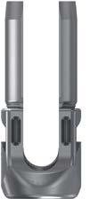
37 SURGICAL TECHNIQUE (continued) 5 DECORTICATION Place the bone Planar (39-MD-0100) over the head of the Modular Screw and rotate the Planar clockwise and counterclockwise to decorticate the bone and allow for optimal seating of the Modular Tulip (Figure 7f). Figure 7f 6 MODULAR TULIP ATTACHMENT Attach the appropriate Modular Tulip using either the Lateral Tulip Clamp (39-SP-0825) or the Angled Lateral Tulip Clamp (39-MD-0825) by aligning the Tulip Clamp with the tabs of the Modular Tulip. Slide the Tulip over the Bone Screw and apply an axial force until an audible click is heard (Figure 7g). Upward pressure of the attached Lateral Tulip Clamp can be applied to ensure that the Tulip is properly inserted. Figure 7g 37


 (Figure 9) and seated flush against the facet and the pedicle. Figure 9 The second site is the transverse process.")
38 SURGICAL TECHNIQUE (continued) 7 HOOK SURGICAL PROCEDURE There are four possible Hook placement sites in the spine: pedicle, transverse process, supra-lamina and infra-lamina. The surgeon must choose the appropriate Hook based on the individual patient s anatomy, deformity degree and type, method of correction chosen, and amount of compression/distraction that will be needed to provide proper and stable purchase of the implants. The first site is the pedicle. Pedicle Hooks (39-TH-010X) are placed in the thoracic spine via the facet joint (Figure 8). The direction for the Pedicle Hooks is always cephalad. Figure 8 The facet of the appropriate level is identified and the capsule is removed. The cartilage on the inferior articular process of the next distal level should be visualized. The facet is entered with the Pedicle Elevator (39- RD-0500). The Pedicle Hook is inserted with the Superior Hook Holder (39-RD-0550) (Figure 9) and seated flush against the facet and the pedicle. Figure 9 The second site is the transverse process. The Angled Hook (39-TH-040X) is recommended for this site. An Elevator is used to dissect around the superior surface of the transverse process and then the Angled Hook is placed in the required position (Figure 10). Figure 10 38
, Straight Laminar (39-TH-020X), Straight Laminar Ext.")


 Hook Down Angled Laminar Hook Offset Angled Laminar Hooks Narrow Ramped Laminar Hook Angled Hook - Right Left Right The fourth possible site is the")

39 SURGICAL TECHNIQUE (continued) 7 HOOK SURGICAL PROCEDURE (cont.) Pedicle Hook Straight Laminar Hooks The third possible site is the superior lamina. The Down Angled Laminar (39-TH-023X), Straight Laminar (39-TH-020X), Straight Laminar Ext. Body (+4mm) (39-TH-021X), Ramped Laminar (39-TH-022X) or Offset Angled Laminar (39-TH-030X) are recommended for this site. The direction is always caudal. These Hooks may be combined with other Hooks to produce a claw construct. The ligamentum flavum is divided in the midline and excised. The amount of bone removed from the lamina may vary depending on the size of the Hook blade and throat angle chosen. The inferior edge of the next proximal lamina is removed to permit the intracanal placement of the Hook. The appropriate Lamina Hook is then placed by using the Hook Pusher (39-RD-0560) until well seated against the lamina. Wide Ext.-Body Laminar (+4mm) Hook Down Angled Laminar Hook Offset Angled Laminar Hooks Narrow Ramped Laminar Hook Angled Hook - Right Left Right The fourth possible site is the inferior lamina. The Down Angled Laminar, Straight Laminar, Ext.-Body Laminar (+4mm), Ramped Laminar or Offset Angled Laminar are recommended for this site in the lumbar spine. The direction is always cephalad. Similar to the Supra-Lamina step, the ligamentum flavum is divided in the midline and excised. The inferior edge of the selected lamina is removed to permit intra-canal placement of the Hook. Straight Laminar Reduction Hook Ext.-Body Laminar (+4mm) Reduction Ramped Laminar Reduction Hook The appropriate Hook is then placed using the Hook Pusher until well seated against the lamina. Down Angled Laminar Reduction Hook Offset Angled Laminar Reduction Hook - Right Angled Reduction Hook - Right 39

 2. Straight Laminar Ext. 3. Body (+4mm) (39-TH-0252) 4. Ramped Laminar (39-TH-0262) 5.")
.")
40 SURGICAL TECHNIQUE (continued) 8 REDUCTION HOOK SURGICAL PROCEDURE The Reform Reduction Hooks are designed to further complement the innovative design of the existing Reform Hook range. These Hooks help to address, correct and also stabilize difficult anatomic variations. The Reduction Hooks are designed with removable tabs that allow the surgeon to approximate the spine to the desired sagittal or axial profile. They are provided in 6 styles similar to the standard Reform Hooks: 1. Straight Laminar (39-TH-0242) 2. Straight Laminar Ext. 3. Body (+4mm) (39-TH-0252) 4. Ramped Laminar (39-TH-0262) 5. Down Angled Laminar (39-TH-0272) 6. Offset Angled Laminar (39-TH-0351; 39-TH-0352) and Angled Laminar (39-TH-0451; 39-TH-0452). Figure 11 Reduction Hooks are most commonly placed at the apex of the concavity. Contour the Rod to match the required spinal contours in the sagittal plane (Figure 11). Utilize each Reduction Hook in the same way as the standard Reform Hooks. Place the contoured Rod into the spine anchors and fully seat. The extended tabs of the Reduction Hooks provide a means of capturing a Rod that may have crossed the midline and would otherwise be out of reach of the anchor (Figure 12). Once the correction procedures have been carried out and the spine is in a satisfactory position, the definitive tightening of the Locking Cap (39-LS-0100) can be completed with the Offset Ratcheting Torque Handle (39-CH-0008), Counter-Torque Wrench (39-RD-0061), and Locking Cap Torque Driver (39-RD-0060). The extended tabs of the Reduction Hook can then be removed by using the Extended Tab Removal Tool (39-RD-0070) (Figure 13). Figure 12 Figure 13 40

. c. The Polyaxial Screw design will allow for some lateral Screw offset.")
 to facilitate insertion into the Screw Head Tulip")
41 SURGICAL TECHNIQUE (continued) 9 ROD INSERTION a. Once all Screws and Hooks have been inserted, the appropriate Straight Rod or Curved Rod may be applied. A Flexible Rod Template (39-RD-0012) or Rotary Caliper (39-CC-0405) may be used to measure the appropriate length Rod. (Figure 14) b. Use the appropriate pre-cut Rod or cut a longer Rod using a rod cutter (rod cutter not provided). c. The Polyaxial Screw design will allow for some lateral Screw offset. Figure 14 d. The Rod can be contoured if desired utilizing the French Rod Bender (39-RD-0001). Note: Repeated bending can weaken the Rod. e. Once the appropriate Rod has been selected, use the Rod Holding Forceps (39-SP-0805) to facilitate insertion into the Screw Head Tulip (Figure 15). f. A Tulip Manipulator (39-SP-0800) may be used to align the Polyaxial Screws Head. Figure 15 41
 for tightening.")
 can be used to seat the Rod.")
 Proceed to Step 11, Locking Cap Insertion.")


 is used when additional force is needed to seat the Rod into the Screw")
.")
42 SURGICAL TECHNIQUE (continued) 10 ROD REDUCTION Figure 16 Figure 17 The Rod must be seated in the Reform Screw head in order to engage the Locking Cap (39-LS-0100) for tightening. There are three alternative instruments used for this process. Option 1 The Rod Pusher (39-SP-0815) can be used to seat the Rod. For constructs with two or more levels, begin with the central Screw. (Figure 16) Proceed to Step 11, Locking Cap Insertion. Option 2 The Rod Rocker (39-RD-0201) can be utilized to seat the Rod within the Screw head (Figure 17). The Rod Rocker easily slides into the lateral slots on the side of the Screw head and is rotated backwards. This levers the Rod into the head of the implant. Note: Placing the Rod Rocker on the side where the Rod is higher may be more effective at getting the Rod seated evenly in the implant (Figure 18). Figure 18 Figure 19 Proceed to Step 11, Locking Cap Insertion. Option 3 The Tie Reduction Tower (39-RD-0310) is used when additional force is needed to seat the Rod into the Screw head. Engage the Tie Reduction Tower on the Screw head with the slots on the Tie Reduction Tower aligned with the rod slot on the Screw head (Figure 19). Place the Tower Reducer (39-RD-0320) over the Tie Reduction Tower and turn the capture sleeve clockwise to reduce the Rod into the Screw head. The T-Handle Reducer (39-RD-0315) can be used if additional force is required (Figure 20). Once the Rod is fully seated, the Locking Cap (39-LS-0100) can be seated using the Locking Cap Retention Driver (39-SP- 0602) (Figure 21). Proceed to vertebral Body Derotation Procedure for advanced techniques. Figure 20 Figure 21 42
. 12 FINAL TIGHTENING Once the correction procedures have been carried out and the spine is in a satisfactory position, the final tightening of the Locking Cap can be commenced.")
43 SURGICAL TECHNIQUE (continued) 11 LOCKING CAP INSERTION For Options 1 & 2 Once the Rod is fully seated, the Locking Cap (39-LS-0100) can be inserted into the Screw head with the Dual Sided Locking Cap Driver (39-SP-0603). 12 FINAL TIGHTENING Once the correction procedures have been carried out and the spine is in a satisfactory position, the final tightening of the Locking Cap can be commenced. Load the square end of the Locking Cap Torque Driver (39-RD-0060) into the Torque Wrench Handle. Place the Counter Torque Wrench (39-RD-0061) over the Reform Screw Head and apply downward pressure to stabilize the Screw Head and Rod. Turn the Torque Wrench Handle clockwise 90 degree and an audible click is heard (Figure 22). Figure 22 43
 and a Narrow style (39-DA-0102).")
 and a Narrow style (39-DA- 0302). There is also an inline, axial connector in a Closed-Closed style (39-AA- 0101).")

44 ADDITIONAL TECHNIQUES 1 DOMINO SURGICAL PROCEDURE Axial Domino Closed-Closed Seven Domino Rod-to-Rod Connectors are offered in the Reform System (Figure 1). Two styles are available in the Closed-Closed Dominoes: a Wide style (39-DA- 0101) and a Narrow style (39-DA-0102). Two styles are available in the Closed-Open Dominoes: a Wide style (39-DA-0201) and a Narrow style (39-DA-0202). Two styles are available in the Open-Open Dominoes: a Wide style (39-DA-0301) and a Narrow style (39-DA- 0302). There is also an inline, axial connector in a Closed-Closed style (39-AA- 0101). The narrow style accommodates parallel Rods that are 8.5mm apart. The wide style accommodates parallel rods that are 11mm apart. Parallel Domino Closed-Closed, Wide Parallel Domino Closed-Open, Wide Parallel Domino Open-Open, Wide Parallel Domino Closed-Closed, Narrow Parallel Domino Closed-Open, Narrow Parallel Domino Open-Open, Narrow Figure 1 Place the appropriate style Domino onto the Longitudinal Rods utilizing the Domino Inserter (39-RD-0570) or the Self-retaining T20 Driver (39-CC-0401). The Self-retaining T20 Driver should be used for preliminary tightening of the preassembled Domino Set Screws (39-LS-0200). Once the desired position of the Domino on the Longitudinal Rods has been achieved, the Torque-Limiting T20 Driver (39-CC- 0407) and the Torque-Limiting Handle (39-CH-0009) should be used for final tightening of the Set Screw to 66 in-lbs. The Domino Inserter (39-RD-0570) can be used as a counter-torque device to stabilize the construct during final tightening (Figure 2 and 2a). Figure 2 Figure 2a 44
 and a Closed-Head connection (39-LO-01XX). Both styles come in lengths of 20, 30, 40, and 50mm.")

45 ADDITIONAL TECHNIQUES 2 LATERAL OFFSET PROCEDURE Eight Lateral Offset designs are offered in the Reform Application. Two styles are available in the Lateral Offsets: a Top Loading Offset connection (39-LO-02XX) and a Closed-Head connection (39-LO-01XX). Both styles come in lengths of 20, 30, 40, and 50mm. All Lateral Offset Connectors will be perpendicular to the Rod when attached (Figure 3). Figure 3 Preload the Lateral Offset onto the Longitudinal Rod. The post of the Lateral offset may be cut and contoured as deemed necessary. A Lateral Offset may also be used at points along the construct to connect to a screw that may be Lateral and out of line with the pedicle screw above and below this point. When tightening the locking screws, first secure the locking screws along the Longitudinal Rod. Then secure each locking screw where it mates with the post of the Lateral Offset within the Lateral Screw. Finally, tighten each locking screw at the Lateral Offset/Longitudinal Rod interface using the Offset Ratcheting Torque Handle and Torque Driver (39-CH-008 & 39-RD- 0060), and Counter Torque Wrench (39-RD-0061) (Figure 4). The locking torque for the Lateral Offset locking screw is 106in-lbs. Figure 4 45

 are provided to engage and retain the Cross-Connector cams during placement (Figure 6).")

46 ADDITIONAL TECHNIQUES 3 CROSS-CONNECTOR SURGICAL PROCEDURE Cross-Connectors can be added to increase the torsional stability of a construct. Long constructs may require Cross-Connectors to be placed at proximal and distal ends of the construct to increase rigidity. The Rotary Calipers can be used to determine the proper length of the Cross-Connector (Figure 5). Two Self-Retaining T20 Drivers (39-CC-0401) are provided to engage and retain the Cross-Connector cams during placement (Figure 6). The midline screw should be loosened to allow for multi-axial flexibility when seating the Cross-Connector onto the constructs. Figure 5 Once each hook portion of the Cross-Connector is fully seated on the Rod, the Self-Retaining T20 Drivers may each be rotated 90 clockwise to fully engage the Cross-Connector cam to the Rod. Next, the midline nut is definitively tightened using the Torque-Limiting T20 Driver (39-CC-0407). An audible click from the Torque-Limiting T20 Driver will confirm that the midline nut is adequately tightened (Figure 7). Figure 6 CROSS-CONNECTOR REMOVAL If removal of a Cross-Connector is necessary, place the Torque-Limiting Screwdriver over the midline nut and turn counter-clockwise to loosen. Place the Self-Retaining T20 Driver into each Cam and turn 90 counter-clockwise to loosen from the Rods. Figure 7 46

. With flexible deformities, locking the proximal and distal ends of the construct (neutral levels) and segmentally reducing can result in translation of the spine.")
 are connected to apical screw heads on both concave and")
 can be attached to the proximal portion of the Tie Reduction Towers.")
47 ADVANCED TECHNIQUE 1 VERTEBRAL BODY DEROTATION PROCEDURE Reduction maneuvers can be performed to manipulate and stabilize deformities of the thoracolumbar spine through the use of segmental anchors and specialized instrumentation. Multiple anchors provide increased rigidity while allowing for safe and consistent correction. Reduction can be achieved by bringing the spine to meet the Rod (as in the case of translation maneuvers) or by simply pushing the Rod to meet the spine to capture the Rod for fixation (cantilever maneuver). With flexible deformities, locking the proximal and distal ends of the construct (neutral levels) and segmentally reducing can result in translation of the spine. Anterior releases or osteotomies may be for correction of more rigid curves. Figure 1 MULTIPLE LEVEL SPINAL DEROTATION In order to complete a multiple level derotation technique, the Tie Reduction Towers (39-RD-0310) are connected to apical screw heads on both concave and convex sides once the concave Rod is in place. If applicable the Tie Tower Reducers (39-RD-0320) may be attached to the Tie Reduction Towers to facilitate Rod reduction. The Tower Connector (39-RD-0344) can be attached to the proximal portion of the Tie Reduction Towers. The Tower Connectors can be aligned to the Tower Bridge, Single (39-RD-0346) or Tower Bridge, Double (39- RD-0347) to aid with rotation. The Tower Connectors are secured to the Tower Bridges via the Tower Thumbscrews (39-RD-0345) (Figure 1). Figure 2 At this point, the derotation maneuver can be performed to bring the spine into alignment (Figures 2 & 3). After reduction is completed, proceed to locking cap insertion. Figure 3 47
 INDIVIDUAL LEVEL SPINAL DEROTATION Individual level spinal derotation can be done as the sole derotation maneuver or in addition to the multiple level maneuver described on the previous page.")
48 ADVANCED TECHNIQUE 1 VERTEBRAL BODY DEROTATION PROCEDURE (cont.) INDIVIDUAL LEVEL SPINAL DEROTATION Individual level spinal derotation can be done as the sole derotation maneuver or in addition to the multiple level maneuver described on the previous page. Implant both Rods and capture them with the Locking Caps. Most Locking Caps should be left loose since lengthening of the spine is expected at each level that will be segmentally derotated. Only the Set Screws in the distal neutral vertebra should be tightened. The Tie Reduction Towers are connected to the affected proximal vertebrae. If applicable, the Tie Tower Reducers (39-RD-0320) may be attached to the Tie Reduction Towers to facilitate rod reduction. The Tower Connector (39-RD- 0344) can be attached to the proximal portion of the Tie Reduction Towers. Figure 4 The Tower Connectors can be aligned to the Tower Bridge, Single (39-RD-0346) or Tower Bridge, Double (39-RD-0347) to aid with derotation. The Tower Connectors are secured to the Tower Bridges via the Tower Thumbscrews (39-RD-0345). At this point, the derotation maneuver can be performed to bring the spine into alignment (Figure 4). Derotate each proximal vertebral body to achieve a neutral position in reference to the neutral distal vertebra. After derotation of each segment, the set screws are tightened. Repeat this process, moving along towards the apex. OPTIONAL SURGICAL PROCEDURES Removal of the Reform Pedicle Screw System components is performed by reversing the order of the implant procedure. NOTE: The Counter-Torque Wrench (39-RD-0061) should be used when removing screws to prevent unintended screw pullout. The Counter-Torque Wrench may be used either directly on the screw to be removed, or on the adjacent screws, to hold the construct in place during removal. 48
49 REFORM KITS 49
50 CONTRAINDICATIONS, POTENTIAL ADVERSE EFFECTS & WARNINGS CONTRAINDICATIONS The Reform Pedicle Screw System contraindications include, but are not limited to: 1. Morbid obesity 2. Mental illness 3. Alcoholism or drug abuse 4. Fever or leukocytes 5. Pregnancy 6. Severe osteopenia 7. Metal sensitivity/allergies 8. Patients unwilling or unable to follow post-operative care instructions 9. Active infectious process or significant risk of infection 10. Any circumstances not listed in the indication of the device POTENTIAL ADVERSE EFFECTS All possible adverse effects associated with spinal fusion surgery without instrumentation are possible. With instrumentation, a listing of potential adverse events includes, but is not limited to: 1. Non-union 2. Fracture of the vertebra 3. Neurological injury 4. Vascular or visceral injury 5. Early or late loosening of any or all of the components 6. Loss of fixation 7. Device component fracture 8. Foreign body (allergic) reaction to implants, debris, corrosion products, graft material, including metallosis, straining, tumor formation, and/or autoimmune disease 9. Disassembly and/or bending of any or all of the components 10. Infection 11. Hemorrhage 12. Change in mental status 13. Pressure on the skin from component parts in patients with inadequate tissue coverage over the implant possibly causing skin penetration, irritation, and/or pain 14. Pain, discomfort, or abnormal sensations due to the presence of the device 15. Post-operative change in spinal curvature, loss of correction, height, and/or reduction 16. Cessation of any potential growth of the operated portion of the spine 17. Loss of or decrease in spinal mobility or function 18. Death Note: Additional surgery may be required to correct some of these potential adverse events. WARNINGS The following are warnings for this device. 1. The safety and effectiveness of pedicle screw spinal systems have been established only for spinal conditions with significant mechanical instability or deformity requiring fusion with instrumentation. These conditions are significant mechanical instability or deformity of the thoracic, lumbar, and sacral spine secondary to degenerative spondylolisthesis with objective evidence of neurological impairment, fracture, dislocation, scoliosis, kyphosis, spinal tumor, and failed previous fusion (pseudarthrosis). The safety and effectiveness of these devices for any other condition is unknown. 2. When used as a pedicle screw system, this system is intended for Grade 3 or 4 spondylolisthesis at the fifth lumbar/first sacral (L5-S1) vertebral joint. 3. Potential risks identified with the use of this device system, which may require additional surgery, include: device component fracture, loss of fixation, non-union, fracture of the vertebrae, neurological injury, and vascular or visceral injury. 4. Benefit of spinal fusions utilizing any pedicle screw fixation system has not been adequately established in patients with stable spines. 5. Single use only. AN IMPLANT SHOULD NEVER BE RE-USED. Any implant, once used, should be discarded. Even though it appears undamaged, it may have small defects and internal stress patterns that may lead to failure. These Single Use devices have not been designed to undergo or withstand any form of alteration, such as disassembly, cleaning or re-sterilization, after a single patient use. Reuse can potentially compromise device performance and patient safety. 6. Failure to achieve arthrodesis will result in eventual loosening and failure of the device construct. 7. To facilitate fusion, a sufficient quantity of autograft bone should be used. 8. Do not reuse implants. Discard used, damaged, or otherwise suspect implants. 9. The implantation of pedicle screw system should be performed only by experienced spinal surgeons with specific training in the use of pedicle screw spinal systems because this is a technically demanding procedure presenting a risk of serious injury to the patient. 10. Based on the fatigue testing results, the physician/surgeon should consider the levels of implantation, patient weight patient, activity level, other patient conditions, etc. which may impact on the performance of the system. 11. Non-sterile; the screws, rods, locking cap screws, cross-links, connectors, hooks, and instruments are sold non-sterile, and therefore must be sterilized before use. 12. The components of this system should not be used with components of any other system or manufacturer. 13. The Reform HA Coated Pedicle Screws are provided sterile. Therefore, cleaning and sterilization are not required. Prior to use, check product packaging for damage, and the expiration date. If found damaged or expired, please contact the manufacturer. All other components of the Reform HA Coated Pedicle Screw system are supplied clean and nonsterile and must be sterilized prior to use. Remove all packaging before sterilization. Implants and instruments should be autoclave sterilized using one of the validated cycle parameters Instructions for Use (IFU) (LBL-IFU-021). 14. Titanium components should not be used with stainless steel components within the same system. 15. This device is not intended for screw attachment or fixation to the posterior elements (pedicles) of the cervical spine. 16. The safety and effectiveness of this device has not been established for use as part of a growing rod construct. This device is only intended to be used when definitive fusion is being performed at all instrumented levels. 50


51 Precision Spine, Inc Executive Drive, Pearl, MS Customer Service: Phone: Toll Free: Fax: Caution: Federal (USA) law restricts these devices to sale by, or on the order of, a physician. Reform and Precision Spine are trademarks of Precision Spine, Inc. Copyright 2018 Precision Spine, Inc. All rights reserved. P/N LBL-STG-030 Rev C 11/2018
PRODUCT SUMMARY Cobalt Chrome Tulip Multiple Options Triple Lead Thread
 PRODUCT SUMMARY Cobalt Chrome Tulip Multiple Options Triple Lead Thread Screws Low Profile 2.72 Footprint x 2.5 Height Square Threaded Locking Cap Geometry reduces risk of cross threading Hexalobular Drive
Surgical Technique FOR U.S. DOMESTIC USE ONLY
 Surgical Technique FOR U.S. DOMESTIC USE ONLY Polyaxial Screws HA Coated Polyaxial Screws Uniplanar Screws Reduction Screws Reduction Uniplanar Screws Modular Screws TABLE OF CONTENTS Reform Pedicle Screw
Y o u r Id e a s En g i n e e r e d t o Li f e
 ISSYS LP Spinal Fixation System Surgical Guide Y o u r Id e a s En g i n e e r e d t o Li f e In t r o d u c t i o n ISSYS LP Sp i n a l Fixation System The foundation of the ISSYS LP Spinal Fixation System
Valencia Pedicle Screw Surgical Technique
 Valencia Pedicle Screw Surgical Technique VALENCIA CIRCUIT TABLE OF CONTENTS Design Rationale Indications for Use Surgical Technique 1. Pedicle Preparation 2. Screw Insertion 3. Rod Placement 4. Locking
X-spine Surgical Technique
 X-spine Surgical Technique The X90 Pedicle Screw System Revolutionary Design and Function This document is intended exclusively for experts in the field, particularly physicians, and is not intended for
EXCELLA ll. Spinal System
 EXCELLA ll Spinal System Excella II Spinal System INDICATIONS FOR USE The Innovasis Excella II Spinal System is intended for use in the non-cervical area of the spine. WARNING: The safety and effectiveness
HydraLok. Operative Technique. Polyaxial Pedicle Screw System
 HydraLok Operative Technique Polyaxial Pedicle Screw System Table of Contents Introduction...1 OPERATIVE TECHNIQUE OVERVIEW...2 DETAILED OPERATIVE TECHNIQUE...4 LOCATE AND PREPARE THE PEDICLE...4 PROBE
Thunderbolt. surgical technique. MIS Pedicle Screw System. Where Nimble and Secure Intersect
 Thunderbolt TM MIS Pedicle Screw System Where Nimble and Secure Intersect surgical technique i www.choicespine.com System Features Dovetail set screw: Minimizes head splay and cross-threading Secure connection
operative technique Universal Application
 operative technique Universal Application Introduction Introduction Building upon the design rationale of the Xia Spinal System, the new Xia Spinal System represents the latest advancement in spinal implant
Threshold Pedicular Fixation System Surgical Technique
 Threshold Pedicular Fixation System Surgical Technique Table of Contents Patient Preparation and Positioning... 2 Determining Incision Location... 3 Assembling the Cannulated Awl... 4 Guide Wire Placement...
SURGICAL TECHNIQUE GUIDE SOLANAS. Posterior Cervico-Thoracic Fixation System Adjustable Bridge System
 SURGICAL TECHNIQUE GUIDE SOLANAS Posterior Cervico-Thoracic Fixation System Adjustable Bridge System 2 SURGICAL TECHNIQUE GUIDE Preface SOLANAS Posterior Cervico-Thoracic Fixation System is designed to
A U X I L I A R Y C O N N E C T O R S Surgical Technique
 A U X I L I A R Y C O N N E C T O R S Surgical Technique AUXILIARY CONNECTORS ISSYS LP Auxiliary Connectors The ISSYS LP auxiliary connectors were designed to provide medial-lateral variability for the
MATRIX Spine System Deformity
 A Solution for Simple and Complex Spine Pathology MATRIX Spine System Deformity Surgical Technique Image intensifier control This description alone does not provide sufficient background for direct use
USS Variable Axis Screw (VAS) System. For posterior fixation of the lumbar spine.
 System. For posterior fixation of the lumbar spine.") USS Variable Axis Screw (VAS) System. For posterior fixation of the lumbar spine. Technique Guide Instruments and implants approved by the AO Foundation Table of Contents Introduction USS Variable Axis
USS Variable Axis Screw (VAS) System. For posterior fixation of the lumbar spine. Technique Guide Instruments and implants approved by the AO Foundation Table of Contents Introduction USS Variable Axis
EXPEDIUM 5.5 Spine System Family Product Catalogue
 EXPEDIUM 5.5 Spine System Family Product Catalogue Including: EXPEDIUM EXPEDIUM Vertebral Body Derotation Universal Connector Set Cobalt Chromium Rods INTRODUCTION Contents EXPEDIUM Spine System is a comprehensive
SerratoTM. Surgical technique
 TM Surgical technique Table of contents Key design features.... 3 System overview.... 4 Surgical technique Patient positioning... 7 Preparing the pedicle.... 8 Screw insertion... 11 Rod contouring... 12
Biomet Omega21 TM Spinal Fixation System
 Biomet Omega21 TM Spinal Fixation System Surgical Technique Coronal Angulation 50% Axial Angulation Infinite Sagittal Angulation Contents Introduction... Page 1 System Design Features And Benefits... Page
Xia 3 Spinal System. AIS surgical technique
 Xia 3 Spinal System Table of contents Surgical technique Key design features.... 4 Patient positioning.... 8 Hook selection... 9 Hook insertion... 10 Preparing the pedicle.... 14 Screw insertion... 19
VERTEX SELECT. surgical technique. adjustability. Flexibility. adaptability. Reconstruction System
 VERTEX SELECT Reconstruction System surgical technique adjustability. Flexibility. adaptability. adjustability. Flexibility. adaptability. The VERTEX SELECT Reconstruction System is a comprehensive set
USS Variable Axis Screw
 USS Variable Axis Screw Polyaxial side-opening pedicle screw Surgical technique Original Instruments and Implants of the Association for the Study of Internal Fixation AO/ASIF USS Variable Axis Screw
 Visit our website on www.biotech-medical.com The DLP - Dorso-Lumbar Polyaxial Screw System has been designed to address the pathologies of the thoracolumbar spine. The DLP System contains a wide range
As edited by Dr. Oheneba Boachie-Adjei, Dr. Matthew Cunningham, Dr. John Kostuik, Dr. Raymund Woo and the Complex Spine Study Group et al
 As edited by Dr. Oheneba Boachie-Adjei, Dr. Matthew Cunningham, Dr. John Kostuik, Dr. Raymund Woo and the Complex Spine Study Group et al RANGE Spinal System A fusion of DENALI and MESA, offering a complete
ONE SYSTEM, MULTIPLE OPTIONS. Surgical Technique. Hip Knee Spine Navigation
 ONE SYSTEM, MULTIPLE OPTIONS Surgical Technique Hip Knee Spine Navigation MUST MINI Surgical Technique Hip Knee Spine Navigation INTRODUCTION The M.U.S.T. Mini posterior cervical screw system is a modular
Dymaxeon Spine System. Simple, Streamlined, Smart. Surgical Procedure
 Simple, Streamlined, Smart Surgical Procedure Introduction The Dymaxeon pedicle screw system offers the spinal surgeon an outstanding system for stabilization of spinal deformity, reduction of spondylolisthesis,
VTI INTERLINK PEDICLE SCREW SYSTEM
 VTI INTERLINK PEDICLE SCREW SYSTEM SURGICAL TECHNIQUE FORWARD THINKING FOR THE BACK. DEVICE DESCRIPTION The VTI InterLink Pedicle Screw System is comprised of polyaxial pedicle screws in various diameters
MATRIX Spine System Deformity. A posterior pedicle screw, hook, and rod fixation system.
 MATRIX Spine System Deformity. A posterior pedicle screw, hook, and rod fixation system. Technique Guide Instruments and implants approved by the AO Foundation Table of Contents Introduction MATRIX Spine
Technique Guide. Universal Spinal System (USS). Designed to achieve the goals of scoliosis surgery.
. Designed to achieve the goals of scoliosis surgery.") Technique Guide Universal Spinal System (USS). Designed to achieve the goals of scoliosis surgery. Table of Contents Introduction Universal Spinal System 2 AO ASIF Principles of Internal Fixation 3 Indications
Technique Guide Universal Spinal System (USS). Designed to achieve the goals of scoliosis surgery. Table of Contents Introduction Universal Spinal System 2 AO ASIF Principles of Internal Fixation 3 Indications
4.5 System. Surgical Technique. This publication is not intended for distribution in the USA.
 4.5 System Surgical Technique This publication is not intended for distribution in the USA. Contents EXPEDIUM 4.5 Spine System 2 Features and Benefits 3 Surgical Technique Extended Tandem Connector 4 Placement
L8 Spine System SURGICAL TECHNIQUE. Add: No.1-8, Tianshan Road, Xinbei District, Changzhou, Jiangsu, China
 Add: No.-8, Tianshan Road, Xinbei District, Changzhou, Jiangsu, China 23022 Tel: 0086 59 8595556 Fax: 0086 59 859555 Http://www.kanghui.com Add: F25, Shanghai International Pharmaceutical Trad & Exhibition
Surgical Technique. Available In Titanium And Stainless Steel
 Surgical Technique Available In Titanium And Stainless Steel Contents Introduction... Page 1 System Design Features... Page 2 Implants... Page 3 Standard Instruments... Page 7 Degenerative Surgical Technique...
EXPEDIUM VERSE Spinal System
 EXPEDIUM VERSE Spinal System SYSTEM GUIDE CONTENTS 1. PRODUCT OVERVIEW 1 FEATURES AND BENEFITS 1 IMPLANT DESIGN 5 INSTRUMENT DESIGN AND SET CONFIGURATION 6 SET CONTENTS 7 2. SURGICAL TECHNIQUE 9 SCREW
Cervical Solutions. Optio-C Anterior Cervical Plate. with Allograft/Autograft. Surgical Technique Guide
 Cervical Solutions Optio-C Anterior Cervical Plate with Allograft/Autograft Surgical Technique Guide 2 Optio-C Anterior Cervical Plate with Allograft/Autograft Surgical Technique Guide The Optio-C System
The Most Reliable Spinal Solution
 MFG : 09.02.20 REV : 1 4CIS VANE introduces you the reliable pedicle screw The Most Reliable Spinal Solution Non-slip threaded joint Ergonomic design Wedged trapezoid thread Superior locking mechanism
Virage OCT Spinal Fixation System Surgical Technique
 Virage OCT Spinal Fixation System Surgical Technique 2 Virage OCT Spinal Fixation System Surgical Technique Virage OCT Spinal Fixation System Surgical Technique Description, Indications & Contraindications...3
RESPONSE SURGICAL TECHNIQUE
 RESPONSE SURGICAL TECHNIQUE SPINE SYSTEM RESPONSE 1 TABLE OF CONTENTS System Overview Pedicle Screw Surgical Technique Hook Surgical Technique Cross Connector Technique Revision or Removal Techniques System
Ref: Q400-09T1 EBI Spine. September 05/VS02. c/o BIOMET Spain Orthopaedics, S.L.
 Ref: Q400-09T1 EBI Spine. September 05/VS02 c/o BIOMET Spain Orthopaedics, S.L. www.ebimedical.com EBI Omega 21 TM LP Since its introduction in 1996, and with thousands of patients treated so far, the
Table of Contents.
 surgical technique The Ambassador TM Anterior Cervical Plate System is a versatile system of implants and instruments with a variety of sizes to provide optimal anatomic compatibility. The integrated cam
Handling instructions. USS Low Profile. Thoracolumbar posterior fixation system.
 Handling instructions USS Low Profile. Thoracolumbar posterior fixation system. U Table of contents Introduction Indications and contraindications 3 USS Low Profile implants 4 Handling implants with stick
A Fusion of Versatility, Performance and Ease.
 MATRIX Spine System. Degenerative and Deformity. System Guide A Fusion of Versatility, Performance and Ease. Instruments and implants approved by the AO Foundation The MATRIX Spine System is a universal
Royal Oak Cervical Plate System
 Royal Oak Cervical Plate System Manufactured by Nexxt Spine, Inc. Royal Oak Cervical Plate System INTRODUCTION FEATURES AND BENEFITS Table of Contents SURGICAL TECHNIQUE Step 1. Patient Positioning Step
I. II. SPINAL SYSTEM SURGICAL TECHNIQUE GUIDE
 I. GS1 II. SPINAL SYSTEM SURGICAL TECHNIQUE GUIDE Introduction The Gold Standard Orthopaedics, LLC GS1 Spinal System designed in conjunction with Richard Holt, M.D. incorporates both strength and function
Thoracolumbar Solutions. Vital Spinal Fixation System. Degenerative. Surgical Technique Guide
 Thoracolumbar Solutions Vital Spinal Fixation System Degenerative Surgical Technique Guide 2 Vital Spinal Fixation System Surgical Technique Guide Vital Spinal Fixation System is an optimized instrument
ONE SYSTEM, MULTIPLE OPTIONS. Surgical Technique
 ONE SYSTEM, MULTIPLE OPTIONS Surgical Technique Joint Spine Sports Med M.U.S.T. Mini Surgical Technique 2 INDEX 1. INTRODUCTION 4 1.1 Indications 4 1.2 Contraindications 4 1.3 Pre-Operative Planning 5
O PE RATIV E TE C HN IQ U E. Minimally Invasive Posterior Fixation
 O PE RATIV E TE C HN IQ U E TM Minimally Invasive Posterior Fixation Table of Contents 1 PRE-OPERATIVE PLANNING Patient Positioning Pedicle Identification and Incision Planning 4 OPERATIVE TECHNIQUE Incision
Dual-Opening USS. For deformity correction.
 Dual-Opening USS. For deformity correction. Technique Guide Instruments and implants approved by the AO Foundation Table of Contents Introduction Dual-Opening USS 2 AO Principles 4 Indications 5 Preoperative
Introduction. Our hope is that this Surgical Technique Guide enhances your knowledge and contributes to clinical success for your patients.
 Surgical Technique Introduction DePuy Spine continues to support the goal of expanding the spine surgeon s options for the treatment of spinal disorders. Collaborating with renowned spine specialists,
BAK/C Cervical Anterior Interbody Fusion System
 Surgical Technique BAK/C Cervical Anterior Interbody Fusion System The Comfortable Choice for Cervical Fusion BAK/C Cervical Surgical Technique 1 The BAK/C Cervical Fusion System is an alternative to conventional
SURGICAL TECHNIQUE. SECURIS Pedicle Screw System for Minimally Invasive Surgery. 2 I SECURIS Pedicle Screw System
 Surgical Technique e Guide SECURIS Pedicle Screw System for Minimally Invasive Surgery Securis Pedicle Screw System has been engineered to provide temporary posterior stabilization of the thoracolumbar
TABLE OF CONTENTS. Vault C Anterior Cervical Discectomy 2 and Fusion (ACDF) System Overview. Implants 3. Instruments 5. Surgical Technique 10
 System Overview. Implants 3. Instruments 5. Surgical Technique 10") Surgical Technique TABLE OF CONTENTS Vault C Anterior Cervical Discectomy 2 and Fusion (ACDF) System Overview Indications 2 Implants 3 Instruments 5 Surgical Technique 10 1. Preoperative planning 10 2.
Surgical Technique TABLE OF CONTENTS Vault C Anterior Cervical Discectomy 2 and Fusion (ACDF) System Overview Indications 2 Implants 3 Instruments 5 Surgical Technique 10 1. Preoperative planning 10 2.
Polaris Deformity System Trivium Derotation System
 Polaris Deformity System Trivium Derotation System A Three Dimensional Approach to Deformity Correction The Polaris Deformity System in combination with the Trivium Derotation System incorporates Enbloc
MATRIX Spine System Degenerative. A posterior pedicle screw and rod fixation system.
 MATRIX Spine System Degenerative. A posterior pedicle screw and rod fixation system. Technique Guide Instruments and implants approved by the AO Foundation Table of Contents Introduction MATRIX Spine
Surgical Technique. Occipito-Cervico-Thoracic System
 OASYS Surgical Technique Occipito-Cervico-Thoracic System System Overview The OASYS Occipito-Cervico-Thoracic System was developed to provide the surgeon with versatility for the treatment of pathologies
Thoracolumbar Solutions. Polaris TM Deformity System. Surgical Technique Guide
 Thoracolumbar Solutions Polaris TM 4.75 Deformity System Surgical Technique Guide 2 Polaris TM 4.75 Deformity System Surgical Technique Guide Comprehensive System Accommodates 4.5mm and 4.75mm Rods Axial
MEDACTA UNCONSTRAINED SCREW TECHNOLOGY - REDUCTION SCREWS. Surgical Technique. Hip Knee Spine Navigation
 .U.S.T. MEDACTA UNCONSTRAINED SCREW TECHNOLOGY - REDUCTION SCREWS Hip Knee Spine Navigation M.U.S.T. Hip Knee Spine Navigation INTRODUCTION The Medacta Unconstrained Screw Technology [M.U.S.T.] Pedicle
The CerviFix System. Including the StarLock Components. CerviFix Clamp and Screw. StarLock Clamp and Screw
 The CerviFix System Including the StarLock Components CerviFix Clamp and Screw StarLock Clamp and Screw The CerviFix System The CerviFix System is a comprehensive set of implants, including clamps, screws,
Occipital Cervical Fusion System. Implants and instruments designed to optimize fixation to the occiput.
 Occipital Cervical Fusion System. Implants and instruments designed to optimize fixation to the occiput. Technique Guide and implants approved by the AO Foundation Table of Contents Introduction Occipital
RESPONSE SURGICAL TECHNIQUE RESPONSE. Spine System
 RESPONSE SURGICAL TECHNIQUE RESPONSE Spine System Table of Contents Refer to the Instructions for Use (package insert) for indications, contraindications, precautions and warnings. For more information,
SURGICAL TECHNIQUE GUIDE TRESTLE. Anterior Cervical Plating System
 SURGICAL TECHNIQUE GUIDE TRESTLE Anterior Cervical Plating System 2 SURGICAL TECHNIQUE GUIDE SURGICAL TECHNIQUE GUIDE System Features Large window enables visualization of graft site and end plates Screw
Thoracolumbar Spine Locking Plate (TSLP) System. A low-profile plating system for anterior stabilization of the thoracic and lumbar spine.
 System. A low-profile plating system for anterior stabilization of the thoracic and lumbar spine.") Thoracolumbar Spine Locking Plate (TSLP) System. A low-profile plating system for anterior stabilization of the thoracic and lumbar spine. Technique Guide Instruments and implants approved by the AO Foundation
Thoracolumbar Spine Locking Plate (TSLP) System. A low-profile plating system for anterior stabilization of the thoracic and lumbar spine. Technique Guide Instruments and implants approved by the AO Foundation
USS II ILIO-SACRAL Modular System for Stable Fixation in the Sacrum and Illium
 USS II ILIO-SACRAL Modular System for Stable Fixation in the Sacrum and Illium Instruments and implants approved by the AO Foundation. This publication is not intended for distribution in the USA. TECHNIQUE
TiLock 2 Spinal System. Surgical Technique
 TiLock 2 Spinal System Surgical Technique Table of Contents Page Preoperative Planning 4 Pedicle Preparation 5 Probe 5 Tap Pedicle 6 Screw Options 7 Screw Insertion 8 Aligning the Windows 9 Rod Insertion
Technique Guide. Pangea Spine System. Top loading pedicle screw and hook system for posterior stabilization and correction of spinal deformities.
 Technique Guide Pangea Spine System. Top loading pedicle screw and hook system for posterior stabilization and correction of spinal deformities. Table of Contents Introduction Pangea Spine System 4 Dual
100 Interpace Parkway Parsippany, NJ
 100 Interpace Parkway Parsippany, NJ 07054 www.biometspine.com 800-526-2579 All trademarks are the property of Biomet, Inc. or one of its subsidiaries, unless otherwise indicated. Rx Only. 2009 EBI, LLC.
EXCELLA MIS. Spinal System
 EXCELLA MIS Spinal System Excella MIS Spinal System INDICATIONS FOR USE The Innovasis Excella MIS Spinal System is intended for use in the non-cervical area of the spine. WARNING: The safety and effectiveness
VECTRA-T SURGICAL TECHNIQUE. The Translational Anterior Cervical Palate System. This publication is not intended for distribution in the USA.
 VECTRA-T The Translational Anterior Cervical Palate System This publication is not intended for distribution in the USA. SURGICAL TECHNIQUE Image intensifier control This description alone does not provide
ACP. Anterior Cervical Plate System SURGICAL TECHNIQUE
 ACP Anterior Cervical Plate System SURGICAL TECHNIQUE ACP TABLE OF CONTENTS INTRODUCTION 4 INDICATIONS AND CONTRAINDICATIONS 5 WARNINGS AND PRECAUTIONS 6 IMPLANT DESCRIPTION 7 INSTRUMENTS 10 SURGICAL
TM TM Surgical Technique
 TM TM Surgical Technique TABLE OF CONTENTS Reli SP Spinous Plating System Overview Device Description Implant Features Indications Instruments Access Instruments Preparation Instruments Insertion Instruments
VENUS SCOLIOSIS. Scoliosis System
 VENUS SCOLIOSIS Scoliosis System System The VENUS Scoliosis System was specially designed for the correction and stabilisation of the spine in particularly complicated anatomies. The system complements
SURGICAL TECHNIQUE. Easyspine PEDICLE SCREW SYSTEM
 SURGICAL TECHNIQUE Easyspine PEDICLE SCREW SYSTEM Easyspine PEDICLE SCREW SYSTEM Designed by leading spine surgeons, Easyspine features a simplified surgical technique and adaptable implants to accommodate
Ballista Percutaneous Screw Placement System. Surgical Technique
 Ballista Percutaneous Screw Placement System Surgical Technique Contents Introduction... Page 1 Features And Benefits... Page 2 Implants... Page 3 Instruments... Page 4 Surgical Technique... Page 8 Indications
Ballista Percutaneous Screw Placement System
 Surgical Technique Ballista Percutaneous Screw Placement System A Minimally Invasive Approach for Posterior Spinal Surgery True percutaneous system Helical Flange locking mechanism Contents Introduction...
SMV Scientific Bone Plate and Screw System Surgical Technique
 SMV Scientific Bone Plate and Screw System Surgical Technique Description: The SMV Scientific Bone Plate and Screw System consists of non-locking plates and bone screw fasteners in a variety of lengths,
POLYAXIAL SPINE SYSTEM D E G E N E R A T I V E
 S U R G I C A L T E C H N I Q U E En POLYAXIAL SPINE SYSTEM D E G E N E R A T I V E LOW PROFILE POLYAXIAL SPINE SYSTEM A01110050 Straight spatula A01110060 Curved spatula A01110070 Bone probe A01114500
Surgical Technique. Guide and Ordering Information. Favored Angle Screw
 Surgical Technique Guide and Ordering Information Favored Angle Screw C O N T E N T S SURGICAL TECHNIQUE Introduction 1 Screwdriver Application and Screw Placement 2 Segmental Translation 3-7 Segmental
Surgical Technique. Guide
 Surgical Technique Guide DESIGNING SURGEONS Darrel Brodke, M.D. University of Utah Medical Center Dept. of Orthopedic Surgery Salt Lake City, Utah Iain Kalfas, M.D., F.A.C.S The Cleveland Clinic Foundation
Trio + Surgical Technique
 Trio + Surgical Technique Introduction Trio+ Surgical Technique The Trio+ Spinal System is a comprehensive system of implants and instruments used for the stabilization of the spine in the thoracic, lumbar,
GIZA Surgical Technique
 GIZA Surgical Technique Vertebral Body Replacement System Manufactured by Titanium alloy material provides mechanical integrity during insertion and distraction, x-ray visibility, and biocompatibility*
MEDACTA UNCONSTRAINED SCREW TECHNOLOGY. Surgical Technique. Hip Knee Spine Navigation
 .U.S.T. MEDACTA UNCONSTRAINED SCREW TECHNOLOGY Hip Knee Spine Navigation M.U.S.T. Hip Knee Spine Navigation CAUTION Federal law (USA) restricts this device to sale distribution and use by or on the order
Imola Lateral IBF System Surgical Technique
 Imola Lateral IBF System Surgical Technique IMOLA CIRCUIT TABLE OF CONTENTS Design Rationale Instructions for Use Surgical Technique 1. Table Mounting 2. Surgical Planning & Targeting 3. Access and Preparation
CSS Combined Spine System
 CSS Combined Spine System H- CSS Combined Spine System H- CSS Combined Spinal System : 800000 H-3 CSS Combined Spinal System : 800000 Ref.Number Description Pieces Ref.Number Description Pieces 00000 Open
Solitaire Anterior Spinal System
 Surgical Technique Solitaire Anterior Spinal System Independent Stabilization for the Anterior Column Available in Titanium and Contents Introduction... Page 1 Design Features... Page 2 Instruments...
Technique Guide. USS Small Stature/Pediatric. A multifaceted deformity system for use in patients of small stature.
 Technique Guide USS Small Stature/Pediatric. A multifaceted deformity system for use in patients of small stature. Image intensifier control Warning This description alone does not provide sufficient background
LUMBAR POSTERIOR MINIMALLY INVASIVE SYSTEM. Surgical Technique
 LUMBAR POSTERIOR MINIMALLY INVASIVE SYSTEM Surgical Technique Joint Spine Sports Med M.U.S.T. Mini Open Surgical Technique Joint Spine Sports Med CAUTION Federal law (USA) restricts this device to sale
Technique Guide MAXIMUM ACCESS SURGICAL PLATFORM
 Technique Guide MAXIMUM ACCESS SURGICAL PLATFORM MAXIMUM ACCESS SURGICAL PLATFORM CONTENTS Preface 1 SpheRx II Anterior Technique Guide 2 Equipment Requirements 2 Patient Positioning and O.R. Setup 2 Staple
AccuVision Minimally Invasive Spinal Exposure System
 Surgical Technique AccuVision Minimally Invasive Spinal Exposure System Working Beyond the Tube Lighted blades for superior viewing Maximum stabilization Contents Introduction... Page 1 Features and Benefits...
Cervical Solutions. Optio-C Anterior Cervical PEEK. Interbody System. Surgical Technique Guide
 Cervical Solutions Optio-C Anterior Cervical PEEK Interbody System Surgical Technique Guide 2 Optio-C Anterior Cervical PEEK Interbody System Surgical Technique Guide The Optio-C System provides a zero-profile
Ascent. Surgical Technique. Breakthrough Thinking. Posterior Occipital Cervico-Thoracic (POCT) System. Germany U.S.A.
 System. Germany U.S.A.") Fusion Motion Preservation Biologics Surgical Technique Breakthrough Thinking Fusion I Motion Preservation I Biologics Posterior Occipital Cervico-Thoracic (POCT) System U.S.A. Corporate Headquarters Blackstone
Fusion Motion Preservation Biologics Surgical Technique Breakthrough Thinking Fusion I Motion Preservation I Biologics Posterior Occipital Cervico-Thoracic (POCT) System U.S.A. Corporate Headquarters Blackstone
M.I.S. MAKE IT SMART IN ONE SYSTEM. Surgical Technique. Hip Knee Spine Navigation
 M.I.S. MAKE IT SMART IN ONE SYSTEM Surgical Technique Hip Knee Spine Navigation M.U.S.T. Mini Open Surgical Technique Hip Knee Spine Navigation 2 C O N T E N T S 1 INTRODUCTION 4 2 SURGICAL TECHNIQUE 5
Technique Guide. NFlex. Semi-rigid rods for posterior lumbar stabilization.
 Technique Guide NFlex. Semi-rigid rods for posterior lumbar stabilization. Table of Contents Introduction NFlex 2 Indications and Contraindications 4 NFlex Principles 6 Surgical Technique Preoperative
TSLP Thoracolumbar Spine Locking Plate
 Anterior thoracolumbar spine locking plate TSLP Thoracolumbar Spine Locking Plate Surgical Technique Image intensifier control This description alone does not provide sufficient background for direct use
Surgical Technique & Product Catalogue. Guide for Open & MIS Procedures
 Surgical Technique & Product Catalogue Guide for Open & MIS Procedures INTRODUCTION The VIPER Cortical Fix Fenestrated Screw System is the first pedicle screw implant to offer enhanced fixation in both
Spinal System Surgical Technique
 Spine Radius Spinal System Surgical Technique Complex Cases Introduction The Radius spinal system incorporates a number of engineering features that makes the system unique. These features include a one-step
Cyprus Anterior Cervical Plate System. Surgical Technique
 Cyprus Anterior Cervical Plate System Surgical Technique Contents Introduction... Page 1 Design Features... Page 2 System Components... Page 3 Surgical Technique... Page 6 Additional Surgical Options...
The Versatile Polyaxial Solution for the Universal Spine Systems. USS II Polyaxial. Surgical Technique
 The Versatile Polyaxial Solution for the Universal Spine Systems USS II Polyaxial Surgical Technique Image intensifier control This description alone does not provide sufficient background for direct use
Trinica and Trinica Select Anterior Cervical Plate System
 Surgical Technique Trinica and Trinica Select Anterior Cervical Plate System A New Twist to Anterior Cervical Plates Trinica and Trinica Select Surgical Technique 1 Trinica and Trinica Select Anterior
Cervical Spacer System surgical technique
 Blackhawk TM Cervical Spacer System surgical technique Blackhawk TM The BLACKHAWK Cervical Spacer System is designed to provide biomechanical stabilization as an adjunct to fusion. Spinal fixation should
EXACTECH SPINE. Operative Technique. Cervical Spacer System. Surgeon focused. Patient driven. TM
 EXACTECH SPINE Operative Technique Cervical Spacer System Surgeon focused. Patient driven. TM ACAPELLA ONE Acapella One Cervical Spacer System is an anterior cervical discectomy and fusion device with
OPERATIVE TECHNIQUE. anterior cervical plating system
 OPERATIVE TECHNIQUE 3º anterior cervical plating system Introduction 1 Pre-Operative Technique 2 Oerative Technique 3 Instructions for Use 12 Part Numbers 16 The surgical technique shown is for illustrative
Technique Guide. MATRIX Spine System MIS Instrumentation. The total solution for simple and complex spine pathology.
 Technique Guide MATRIX Spine System MIS Instrumentation. The total solution for simple and complex spine pathology. Table of Contents Introduction MATRIX Spine System MIS Instrumentation 2 AO Principles
Veyron -C Anterior Cervical System Surgical Technique
 Veyron -C Anterior Cervical System Surgical Technique 2 Veyron-C Anterior Cervical System Surgical Technique Veyron-C Anterior Cervical System Surgical Technique Description, Indications & Contraindications...3