SerratoTM. Surgical technique
|
|
|
- Christian Stevens
- 5 years ago
- Views:
Transcription

1 TM Surgical technique
2 Table of contents Key design features System overview Surgical technique Patient positioning... 7 Preparing the pedicle Screw insertion Rod contouring Rod contouring / insertion Blocker positioning Rod persuasion / reduction Reduction procedures Rod compression / distraction Final tightening Cross connectors Implants Instruments Appendix General conditions of use Serrato is a line extension of Xia 3 that is compatible with Xia 3 and ES2 systems 2


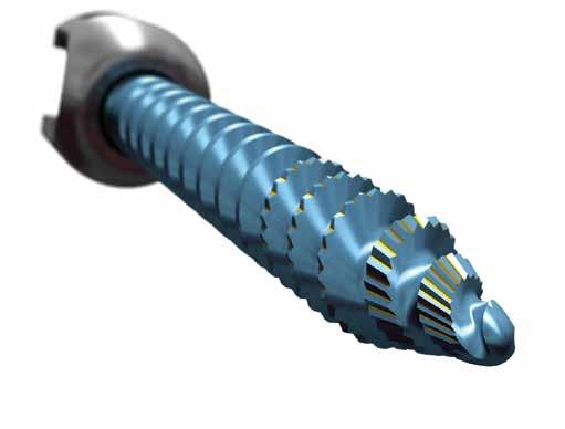
3 Key design features Serrato polyaxial screw Proven buttress thread locking Over 5.5 million blockers with consistent performance, the buttress thread blocker helps to eliminate crossthreading, prevent screw head splaying and helps to ensure a secure closure Rod options Serrato screws accommodate a variety of rod diameters and materials; 5.5 and 6.0mm diameter rods in commercially pure titanium, titanium alloy and Vitallium Cortical/cancellous dual-thread pattern Based on patient anatomy, the Serrato bone screw dual-thread pattern is designed to maximize performance and purchase in cortical and cancellous vertebral bone Cancellous threads: Tapered minor diameter results in deeper thread form at the distal half of the screw to maximize trabecular bone engagement of the vertebral body and enhance cancellous bone screw purchase Cortical threads: Once implanted, the shallower minor diameter at the proximal portion of the screw creates compression of the pedicle bone, press fitting the screw into the bone to promote solid cortical bone screw fixation Dual lead threads An increased number of leads allows for a rapid speed of insertion. Reduced work / insertion force Serrations act as 24 circumferential enhanced cutting flutes to lower insertion torque while maintaining equivalent pull-out compared to duallead screws with traditional cutting flutes True-tip Precise tip combined with an extended thread profile allows for immediate engagement in the desired trajectory with accurate control and reliable insertion Screw to screwdriver interface 6-point star engagement between the screwdriver and screws is designed to decrease toggle, intuitively align when loading and re-engage for screw adjustments. The 6-point star screw head is designed: For faster and more intuitive engagement with the screwdriver To prevent screw head stripping For reengagement during screw adjustments 3


4 System overview Serrato screws Titanium screw tulips are anodized by screw diameter. All shanks of Serrato screws are blue for ease of identification. Note: The top surface of the Serrato tulip has laser marked lines to differentiate between Serrato and Xia 3. Serrato thread pattern is designed for optimal performance and purchase in cortical and cancellous vertebral bone. Polyaxial screws / cannulated polyaxial screws Medial biased screws Reduction screws Screw options Polyaxial Diameter 4.5mm 5.5mm 6.5mm 7.5mm 8.5mm 9.5mm Length 30mm-45mm 30mm-50mm 30mm-80mm 30mm-100mm 70mm-100mm 70mm-100mm Cannulated Polyaxial Diameter 5.5mm 6.5mm 7.5mm Length 30mm-60mm 30mm-60mm 30mm-60mm Reduction Polyaxial Diameter 5.5mm 6.5mm 7.5mm Length 30mm-60mm 30mm-60mm 30mm-60mm Medial Biased Diameter 7.5mm 8.5mm Length 70mm-90mm 70mm-90mm 4

5 System overview Taps Taps have color-coded bands to facilitate coordination to the same diameter screw tulips. Taps are available in 3.5 to 10.5mm sizes for non-cannulated and 4.5 to 7.5mm for cannulated polyaxial screws. Note: The nomenclature describing the taps represents the actual tap line to line diameter. Navigation compatibility note: Serrato can be used with Stryker s Navigated Serrato, Mantis Reduction and Xia 3 instruments. The Navigated Serrato, Mantis Reduction and Xia 3 instruments are dedicated instruments for pedicle preparation and screw insertion. Please refer to Stryker s Navigated Spine Instruments Quick Guide for instruction on using the Navigated Serrato, Mantis Reduction and Xia 3 instruments with Serrato screws. Non-cannulated Cannulated 3.5mm Tap mm Tap mm Tap mm Tap mm Tap mm Tap mm Tap mm Tap mm Tap mm Tap mm Tap mm Tap The first 40mm from the distal end of the tap is covered by a gold coating with the bold single digits in 10mm increments to aid in finding depth. The laser marked lines are in 5mm increments to provide additional detail in depth measurements. 5

6 System overview Polyaxial screwdriver The Serrato Polyaxial Screwdriver has been redesigned to minimize obstruction of the surgeon s line of sight during screw insertion in addition to increasing versatility. The driver is compatible with all Serrato and Xia 3 screw types with the touch of a button; cannulated, reduction and standard polyaxial screws. The Serrato Polyaxial Screwdriver can be connected to any of the quick connect handles in this guide. The Serrato Polyaxial Screwdriver was designed to help decrease toggle at two integral points of connection: Screwdriver to screw interface Screwdriver to handle interface The screwdriver locking feature is designed to provide tactile and visual confirmation that the screwdriver is securely locked. Quick Connect Adaptor Lock/Unlock Button Reduction Button Outer Sleeve Power indication note: Serrato screws can be inserted with the use of Stryker s RemB Universal Driver or the CD3 Cordless Driver with the Power Adaptor attached to the Serrato Polyaxial Screwdriver. Please refer to the appropriate surgical technique from Stryker s Instruments division when using power for screw insertion with Serrato. Navigation compatibility note: Serrato can be used with Stryker s Navigated instruments. The Navigated instruments are dedicated instruments for pedicle preparation and screw insertion. Please refer to Stryker s Navigated Spine Instruments Quick Guide for instruction on using the navigated instruments with Serrato. Unlocked Inner Shaft Locked Polyaxial Screwdriver Standard Short S 6


7 Surgical technique Patient positioning Diagnosis is based upon patient history, physical findings and preoperative radiographic assessment. The patient can be positioned on the operating table in the prone position. Care should be taken to pad all boney prominences. To facilitate venous drainage, the abdomen should not be compressed. Surgical levels may be verified either clinically or radiographically. To help ensure adequate exposure, extend the incision just beyond the length of the intended fusion. Presurgical planning defines the most appropriate implants in addition to the optimal location for insertion of implants. Note: If preferred, the cannulated screws may be used with a guidewire. Please refer to the technique detailed in the ES2 surgical technique MIES2_ST-1. 7

8 Surgical technique Preparing the pedicle Once anatomical landmarks are identified, remove the cortical crest with a rongeur or power burr to expose the underlying cancellous bone. Prepare the entry point with the Awl. 13mm depth stop Awl

9 Surgical technique Using a probe, create a pathway into the pedicle. The correct rotational insertion of the instrument allows the probe to follow a path of least resistance without violating the pedicle walls. If resistance occurs, reevaluate the entry point and trajectory. Curved Blunt Probe There are different probe options available with Serrato with the primary differentiating feature being the tip. The Curved Blunt Probe has a flat tip. The Thoracic Pedicle Probe has a sharp, pointy tip designed to optimize its use in the thoracic region of the spine. The Curved Blunt Probe and the Thoracic Pedicle Probe are laser marked in 5mm intervals to help indicate the depth in which the probe has been inserted. These depth indicators on the probes are also helpful in determining the appropriate screw length. Thoracic Pedicle Probe Note: The Curved Blunt Probe must not be used to prepare holes for 4.0mm diameter screws. The Thoracic Pedicle Probe is recommended for 4.0mm diameter screws. Pedicle Feelers are laser marked with lines in 10mm increments. Follow the prepared pathway with the Pedicle Feeler to confirm the walls of the pedicle have not been violated. Pedicle Feeler - Malleable Pedicle Feeler - Medium Pedicle Feeler - Stiff Double Ended Pedicle Feeler


10 Surgical technique For increased bone purchase, use the Taps to prepare the pedicle canal. After attaching a Xia 3 handle, insert the Tap into the pedicle and into the vertebral body. Laser-marked lines are shown in 5mm increments. Number indicators are listed in 10mm increments and shown in single digits for ease of visualization. 10

11 Surgical technique Taps can be attached to any of the handles pictured at right. Reference number Description Note: The Jacobs Chuck Handle is another handle option for Serrato. This handle can be hand tightened or the chuck key can be used to secure the handle. Ensure proper engagement between the handle teeth and the instrument shaft surface. Note: The Cannulated Handles are handle options for Serrato. These handles can be used with cannulated Serrato screws T-Handle T-Handle, Ratchet Round Handle Round Handle, Ratchet Small Round Handle, Ratchet Small Round Handle Jacobs Chuck Handle Cannulated T-Handle, Ratchet Cannulated Round Handle, Ratchet Screw insertion With the pedicle pathway prepared, and the proper screw diameter and length determined, insert the screw into the pedicle using the appropriate screwdriver. The Serrato polyaxial titanium self-tapping screws have serrations to ease screw insertion. However, in most cases, tapping is recommended. Note: For screwdriver assembly, refer to page 29 in Appendix A: Instrument assembly. 11


12 Surgical technique Rod contouring The Serrato screws are designed to accommodate 5.5 and 6.0mm diameter rods. A variety of size and stiffness options is designed to accommodate a spectrum of surgical needs. Pre-bent rods are also compatible with this system. Laser markings serve as a point of reference for bending the rod Male hex end is often used for derotation Table-Top Rod Cutter and Stand S Note: Straight rods 90mm and greater have hex ends. Once all the screws are inserted, use the Rod Template to determine the appropriate rod length. Use the appropriate pre-cut rods or cut a longer rod to the desired length using the Table-Top Rod Cutter and Stand. French Benders Rod Template Bend the rod to fit the desired spinal contours using either the French Benders or the Tube Benders. To contour the rod, a series of small incremental adjustments will bend the rod gradually and help ensure even stress distribution on the rod. Note: Do not repeatedly contour the rod. Care should be taken to not make extreme bends, so as to avoid stress concentration and notching of the rod. Do not contour a bent rod in the opposite direction; bending and unbending the rod. Tube Benders L R 12


13 Surgical technique Rod contouring / insertion Once the rod is bent to the desired contour, use the Rod Insertion Forceps or Rod Gripper to help place the rod into the grooves of the implant. Rod Insertion Forceps Rod Gripper The In Situ Rod Benders and the Coronal Plane Benders can be used to achieve final incremental correction maneuvers. Care should be taken to not make extreme bends as that can cause stress concentration and notching of the rod. In Situ Rod Benders L, R Coronal Plane Benders , Ball Joint S 13

14 Surgical technique Blocker positioning Serrato uses the Xia Buttress Thread Blocker closure mechanism. Assemble the blocker to the Universal Tightener for insertion. Rod persuasion / reduction Serrato offers five options for linking the rod to the spine. Blocker The Universal Tightener is available in three different options; standard, short and double-ended. The two engraved lines on the Universal Tightener denote the following: When the lower line is aligned with the top of the Inserter Tube, the blocker is at the top of the implant. When the upper line is aligned with the top of the Inserter Tube, the blocker is fully introduced into the implant. Note: The lower and upper indication lines reflect the above described positions of the blocker in relation to the implant when the Standard Universal Tightener is used with the Standard Inserter Tube, and when the Short Universal Tightener is used with the Short Inserter Tube. The Standard Universal Tightener can be used with the Short Inserter Tube, but the lower and upper indication lines will not denote the position of the blocker with respect to the implant. Do not use the Short Universal Tightener with the Standard Inserter Tube. Note: The Universal Tightener is not to be used for final tightening. Split hex design for secure engagement to blocker Universal Tightener Double-Ended Universal Tightener Short Universal Tightener Inserter Tube Short Inserter Tube


15 Surgical technique Option 1: Inserter Tube and Universal Tightener The Inserter Tube helps align the Universal Tightener and the blocker with the implant. Inserter Tube Short Inserter Tube Option 2: Rod Fork and Universal Tightener When the rod is slightly proud with respect to the seat of the implant, the Rod Fork can be used. Slide the Rod Fork into the lateral grooves on the implant head and lever the arm towards the rod. This motion levers the rod into the head of the implant. When the rod is fully seated into the head of the implant, insert the blocker with the Universal Tightener. Rod Fork Note: The Universal Tightener is not to be used for final tightening. 15


16 Surgical technique Option 3: Persuader Use the Persuader when additional force is needed to bring the rod to the implant. The Persuader is available in two sizes; standard and short. The Persuader has two windows at the top and two windows at the bottom of the instrument for visibility. The Hex Drive T-Handle can be attached to the Persuader for additional leverage. Hex Drive T-Handle There are three key indication lines on the Persuader: At 0, the Persuader can be connected to the implant. At 1, the Persuader is locked to the implant. At 2, the rod is fully seated. Verify the indication line on the Persuader is in the 0 starting position. Connect the Persuader to the head of the implant. Rotate the handle of the Persuader clockwise until the indication line is in the 1 position. At this position the Persuader is locked to the implant and the rod can be pushed into the screw. Persuader Short Persuader Rotate the handle of the Persuader clockwise until the indication line is in the 2 position. At this position, the rod is fully seated and the blocker can be inserted using the Universal Tightener. To remove the Persuader, rotate the handle counterclockwise until the indication line is in the 0 starting position and twist the instrument to disengage from the implant. Note: Blockers can be inserted through the Persuader into the screw heads. The Short Universal Tightener will not work with the Standard Persuader. Note: The Universal Tightener is not to be used for final tightening. Caution: Extra caution is advised in the following cases: The rod is not horizontally placed into the screw head. The rod is high in the screw head. An acute convex or concave bend is contoured into the rod. 16


17 Surgical technique Option 4: One Handed Persuader The One Handed Persuader is designed to quickly and easily bring the rod to the implant. Connect the One Handed Persuader to the head of the implant with the handle in the open position. Squeeze the handle until it reaches the shaft of the instrument. As the handle is depressed, the rod is brought to the implant. Ergonomic Handle Lock Release Designed with a natural stop, the One Handed Persuader provides tactile feedback and helps prevent over persuasion. In addition, the ratchet sound provides audible feedback to confirm the rod is fully seated. At this point, the blocker can be inserted with the Universal Tightener. One Handed Persuader To remove the One Handed Persuader, slide the lock release and twist the instrument to disengage from the screw. Note: Blockers can be inserted through the One Handed Persuader into the screw heads. The Short Universal Tightener will not work with the One Handed Persuader. Note: The Universal Tightener is not to be used for final tightening. In the event the rod is forced down while tightening the blocker, be sure that the blocker is fully engaged into the screw head. This will help resist the high reactive forces generated by the final tightening maneuvers. 17

 from the SUK DVR System can be connected to the proximal end of the tube for additional leverage.")
18 Surgical technique Option 5: SUK Reduction Tube The SUK Reduction Tube was designed to function as both a reduction instrument and an instrument that can be used for direct vertebral rotation. The Reduction Clip was designed to be a low profile reduction instrument. SUK Reduction Tube Attach the inner sleeve of the SUK Reduction Tube to the notches on the tulip head of the screw. Rotate the outer sleeve clockwise until the rod is fully seated in the tulip head. If additional torque is needed to persuade the rod, a T-Handle ( ) from the SUK DVR System can be connected to the proximal end of the tube for additional leverage. Reduction Clip Once the outer sleeve has been fully threaded down and a secure connection ensured, the SUK Reduction Tube can now be used in direct vertebral rotation maneuvers. SUK DVR T-Handle Note: Blockers can be inserted through the SUK Reduction Tube into the screw heads. The Short Universal Tightener will not work with the SUK Reduction Tube. Note: The Universal Tightener is not to be used for final tightening. Note: For full instructions on disassembly and cleaning for the Xia 3 SUK Tubes, refer to page 31 in Appendix A. SUK Tube - One Piece The low profile of the Reduction Clip allows multiple clips to be used on adjacent segments. 18


19 Surgical technique Reduction procedures Serrato reduction screws can be used to help reduce the rod to the spine, or the spine to the rod. Use the Serrato Screwdriver to insert the Serrato reduction screws into the pedicles. Serrato Reduction Polyaxial Screw Note: Serrato reduction screws offer 15mm of threaded reduction in the extended tab portion of the tulip. Note: To connect a reduction screw to the Serrato Screwdriver, follow the procedure as described on page 29 in Appendix A: Instrument Assembly Reduction Polyaxial Reduction screws are visibly distinguishable from standard Serrato screws by the extended tabs of the tulip heads. The Serrato reduction screws are available in the following sizes: Diameter 5.5mm 6.5mm 7.5mm Length 30mm-60mm 30mm-60mm 30mm-60mm When the reduction is complete, use the Reduction Screw Tab Remover to grip the reduction tabs and bend in a back and forth motion. A snap line allows a clean and easy break. Reduction Screw Tab Remover Perform final tightening only after all reduction tabs are broken off from the screws


20 Surgical technique Rod compression / distraction To compress or distract: Spinal deformities can also be affected by creating a distraction on the concavity of the deformity and compression on the convexity of the deformity. It is important to perform these maneuvers once all of the blockers are inserted but not final tightened. To accommodate a range of correction needs, small and large Compressors and Distractors are available. Small Compressor Large Compressor Small Distractor Large Distractor Compression Dual axis pivot points evenly distribute compression and distraction loads Straight and parallel tips facilitate parallel compression and distraction Large Compressor Large Distractor Distraction 20


21 Surgical technique Final tightening Use the Anti-Torque Key and the Torque Wrench to final tighten the blockers. The Anti-Torque Key must be used for final tightening. The Anti-Torque Key performs two key functions: Allows the Torque Wrench to align with the tightening axis. Helps to maximize the torque needed to lock the implant assembly. Place the Anti-Torque Key over the screw head. Place the Torque Wrench through the Anti-Torque Key into the blocker. The Torque Wrench indicates the optimal torque force that must be applied to the implant for final tightening. Line up the two arrows to achieve the final tightening torque of 12Nm. Anti-Torque Key Small Anti-Torque Key Xia 3 Torque Wrench Small Torque Wrench Note: Do not exceed 12Nm during final tightening. ES2 Counter Torque Tube Note: The Small Torque Wrench will not fit through the standard Anti-Torque Key. Note: The ES2 Torque Wrench or the MANTIS Redux Torque Wrench may also be used as an alternative to the Xia 3 Torque Wrench to final tighten the blockers. Note: The ES2 Counter Torque Tube may also be used in conjunction with the Xia 3 Torque Wrench. ES2 Torque Wrench

22 Surgical technique Cross connectors Cross Connectors are recommended for increased rotational stability of the construct. Once the final tightening of the construct is complete, choose the appropriate cross connector size by using the Cross Connector Measuring Device or the MAC Caliper. Cross Connector Measuring Device To allow for smooth and rapid insertion of the cross connector over the rods, ensure the 8mm central nut is loose. This facilitates full range of motion. Ensure the 3.5mm set screws are adequately backed out. Use the Cross Connector Inserter to place the appropriate length connector on the rod. Use the 3.5mm Hex Driver or the Double-Ended 3.5mm Set Screw Inserter to provisionally tighten one of the set screws onto the rod. MAC Caliper Cross Connector Inserter mm Hex Driver Double-Ended 3.5mm Set Screw Inserter Continue with the insertion of the cross connector by fully tightening the second set screw. Return to the first set screw for further tightening. 8mm Hex Driver Confirm that the cross connector is correctly connected to the rods. For final tightening, the 3.5mm Hex Driver must be used to tighten the set screws, and the 8mm Hex Driver must be used to final tighten the central nut. Multi-Axial Cross Connector Monoblock Cross Connector 22
23 Implants Reference number Sterile* reference number Description S Blocker (20)-(45) N/A Ø4.0 x 20-45mm Polyaxial Screw (20)-(45) N/A Ø4.5 x 20-45mm Polyaxial Screw (20)-(50) N/A Ø5.0 x 20-50mm Polyaxial Screw (25)-(60) N/A Ø5.5 x 25-60mm Polyaxial Screw (25)-(130) N/A Ø6.0 x mm Polyaxial Screw (25)-(130) N/A Ø6.5 x mm Polyaxial Screw (25)-(130) N/A Ø7.0 x mm Polyaxial Screw (25)-(130) N/A Ø7.5 x mm Polyaxial Screw (25)-(130) N/A Ø8.5 x mm Polyaxial Screw (40)-(130) N/A Ø9.5 x mm Polyaxial Screw (40)-(130) N/A Ø10.5 x mm Polyaxial Screw (30)-(60) N/A Ø5.5 x 30-60mm Reduction Polyaxial Screw (30)-(60) N/A Ø6.5 x 30-60mm Reduction Polyaxial Screw (30)-(60) N/A Ø7.5 x 30-60mm Reduction Polyaxial Screw (30)-(60) N/A Ø5.5 x 30-60mm Cannulated Polyaxial Screw (30)-(60) N/A Ø6.5 x 30-60mm Cannulated Polyaxial Screw (30)-(60) N/A Ø7.5 x 30-60mm Cannulated Polyaxial Screw (70)-(90) N/A Ø7.5 x 70-90mm Medial Biased-Angle Polyaxial Screw (70)-(90) N/A Ø8.5 x 70-90mm Medial Biased-Angle Polyaxial Screw *Sterile implants are only available in certain markets outside the U.S. Please contact your Stryker Sales Representative for more information. ** Serrato is compatible with Xia 3 and ES2 Systems 23
24 Implants Reference number Sterile* reference number Description 48232(030)-(150) 48232(030)-(150)S Xia 3 Ø6.0 x mm CP Ti Rod S Xia 3 Ø6.0 x 480mm CP Ti Rod N/A Xia 3 Ø6.0 x 600mm CP Ti Rod 48233(030)-(150) 48233(030)-(150)S Xia 3 Ø6.0 x mmTi Alloy Rod N/A Xia 3 Ø6.0 x 480mm Ti Alloy Rod N/A Xia 3 Ø6.0 x 600mm Ti Alloy Rod N/A Xia II Ø6.0 x 600mm Vitallium Rod N/A Xia 3 Ø6.0 x 600mm Vitallium Rod, with hex 48238(030)-(120) 48238(030)-(120)S Xia 3 Ø6.0 x mm Ti Alloy Rad Rod 48239(050)-(120) 48239(050)-(120)S Xia 3 Ø6.0 x mm Ti Alloy Max Rad Rod 48235(030)-(045) N/A Xia 3 Ø6.0 x 30-45mm Vitallium Rad Rod 48235(050)-(120) N/A Xia 3 Ø6.0 x mm Vitallium Rad Rod with hex N/A Xia 3 Ø6.0 x 240mm Vitallium Straight Rod with hex N/A Xia 3 Ø6.0 x 480mm Vitallium Straight Rod with hex (03)-(20) N/A Radius Ø5.5 x mm Titanium Spinal Rod, without hex (110)-(600) N/A Radius Ø5.5 x mm Titanium Spinal Rod, with hex N/A Radius 600mm Vitallium Spinal Rod N/A Radius Ø5.5 x 600mm Vitallium Spinal Rod, with hex N/A Radius Ø5.5 x 240mm Vitallium Spinal Rod, without hex N/A Radius Ø5.5 x 240mm Vitallium Spinal Rod, with hex *Sterile implants are only available in certain markets outside the U.S. Please contact your Stryker Sales Representative for more information. 24
25 Implants Reference number Sterile* reference number Description (30)-(20) N/A Radius Ø5.5 x mm Titanium Rad Rod (60)-(20) N/A Radius Ø5.5 x mm Titanium Rad Rod, with hex (30)-(20) N/A Radius Ø5.5 x mm Vitallium Rad Rod (50)-(20) N/A Radius Ø5.5 x mm Titanium Max Rad Rod (14)-(26) (14)-(26)S Xia mm Monoblock Cross Connector S Xia mm Multi Axial Cross Connector S Xia mm Multi Axial Cross Connector S Xia mm Multi Axial Cross Connector S Xia mm Multi Axial Cross Connector S Xia mm Multi Axial Cross Connector S Xia mm Multi Axial Cross Connector S Xia 3 12mm Parallel Revision Connector Open-Closed S Xia 3 22mm Parallel Revision Connector Open-Closed S Xia 3 11mm Closed Parallel RRC S Xia 3 Angled Loading - Side Loading RRC S Xia 3 Top Loading - Side Loading RRC S Xia 3 Axial Revision RRC S Xia 3 Low Profile Long Closed Offset Connector S Xia 3 Small Closed Head Offset Connector S Xia 3 Long Offset Connector Open-Head S Xia 3 7mm Closed Parallel RRC S Xia 3 J Hook Offset Connector S Xia 3 Open Side-Loading Offset Connector *Sterile implants are only available in certain markets outside the U.S. Please contact your Stryker Sales Representative for more information. 25
26 Instruments Reference number Awl Description Curved Blunt Probe Reference number S S Description Short Polyaxial Screwdriver Short Screwdriver Sleeve Thoracic Pedicle Probe Pedicle Feeler - Malleable Pedicle Feeler - Medium Pedicle Feeler - Stiff S Short Polyaxial Screwdriver Shaft Xia II Rod Template S Table-Top Rod Cutter Stand Table-Top Rod Cutter Double Ended Pedicle Feeler French Bender T-Handle L Tube Bender Left T-Handle, Ratchet R Tube Bender Right Round Handle Round Handle, Ratchet Rod Insertion Forceps Rod Gripper Small Round Handle, Ratchet L In Situ Rod Bender Left Small Round Handle R In Situ Rod Bender Right Jacobs Chuck Handle Coronal Plane Bender Left 48260(030)-(0105) Serrato Taps Ø3.0mm - Ø10.5mm Coronal Plane Bender Right (45)-(75) 48260( ) Serrato Cannulated Taps Ø4.5mm - Ø7.5mm Navigated Serrato Taps Ø4.0mm - Ø10.5mm Polyaxial Screwdriver Polyaxial Screwdriver Shaft Screwdriver Sleeve Screwdriver Locking Nut Quick Connect Adapter S Ball Joint Universal Tightener Short Universal Tightener Double-Ended Universal Tightener Inserter Tube Short Inserter Tube Rod Fork 26
27 Instruments Reference number Description Reference number Description Persuader Reduction Clip Short Persuader SUK Tube - One Piece One Handed Persuader SUK Tube - Two Piece Small Compressor SUK DVR Reduction Tube Large Compressor T-Handle, SUK Tube Small Distractor SUK Derotator Clamp Large Distractor Short SUK DVR Clamp Anti-Torque Key* Long SUK DVR Clamp Small Anti-Torque Key* Reduction Screw Tab Remover Xia 3 Torque Wrench Vise Grip Xia 3 Small Torque Wrench Rod Pusher ES2 Torque Wrench Monodriver MANTIS Redux Torque Wrench Short Monodriver ES2 Counter Torque Tube Modular Monodriver Shaft Cross Connector Measuring Device MAC Caliper Modular Polyadjustment Driver Xia 3 Self-Holding Polyaxial Screwdriver Shaft Cross Connector Inserter mm Hex Driver Double-Ended 3.5mm Set Screw Inserter mm Hex Driver Rod Rotation Key (Ø6.0mm) mm Combination Wrench (Ø5.5mm) Pedicle Marker Inserter Pedicle Markers (Set of 6) Navigated Xia 3 Screwdriver Navigated Mantis Reduction Screwdriver Soft Tissue Retractor *Xia 2 Anti-Torque Keys can be used with Serrato 27
28 Instruments Xia 3 System - Serrato Xia 3 System Reference number Description Reference number Description Polyaxial Screw Tray Degenerative Implant Tray Cannulated Screw Tray Degenerative Instrument Tray Reduction Screw Tray Complex Spine Implant Tray Large Diameter Screw Tray Complex Spine Instrument Tray Navigated Instrument Tray Complex Spine Rod and Cross Connector Tray Polyaxial Screw Caddy Degenerative Implant Tray Version B (SS) Cannulated Screw Caddy Degenerative Instrument Tray Version B (SS) Reduction Screw Caddy SUK Tray Large Diameter Screw Caddy Outlier Implant Tray Rod Caddy Outlier Instrument Tray Blocker Caddy Cross Connector Caddy Auxiliary Tray 28


29 Appendix A: Instrument assembly To assemble and engage the Serrato Polyaxial Screwdrivers: STEP 1: Insert the Polyaxial Inner Shaft into the Outer Sleeve. Depress the black button to fully insert the shaft. STEP 5: Depress the Lock/Unlock Button and slide upward towards the Quick Connect Adaptor. STEP 2: Slide the Lock/Unlock Button onto the Inner Shaft with the gears positioned distally towards the sleeve. STEP 6: Hold the screw by the threads and engage the tabs on the Screwdriver Inner Shaft into the saddle of the screw head. STEP 3: Slide the Quick Connect Adaptor down the Inner Shaft until it stops proximal to the Lock/ Unlock Button. STEP 7: Fully seat the Inner Shaft into the screw head. Turn the Outer Shaft clockwise until the threads are fully engaged. STEP 4: Align the tabs of the Quick Connect Adaptor and fully insert the quick connect mechanism into the shaft. Note: Once fully engaged, the shaft alignment tabs will be almost flush with the cutout in the tulip. STEP 8: Depress the Gold Lock/Unlock Button and slide it distally along the Inner Shaft into the Outer Sleeve until the button clicks in place. 29


30 Appendix A: Instrument assembly To engage the reduction position for the Serrato Screwdriver: STEP 1: Without a screw attached, depress the Gold Lock/Unlock Button and slide it proximally towards the Quick Connect Adaptor. STEP 2: Depress the black button on the thicker portion of the Outer Sleeve and, while depressed, slide the Outer Sleeve proximal up the Inner Shaft until it clicks into place 15mm distal from the previous position. Note: Perform the same screw attachment steps as described above regarding polyaxial screw engagement to engage a reduction screw. Note: To place the screwdriver back into the original position, depress the black Reduction Button on the Outer Sleeve and, with the button depressed slide the Outer Sleeve distally down the Inner Shaft until it clicks in place. To disengage and disassemble the Serrato Polyaxial Screwdriver: Once the screw is placed, reverse the screwdriver assembly steps on page 29 to disengage and disassemble the screwdriver. 30
31 Appendix A: Instrument assembly Xia 3 SUK Tubes disassembly instructions for cleaning 2 STEP 1: Unthread the outside tube (1) from the inside tube (2). 1 STEP STEP 2: Once the first level of threads is cleared, slide the outside sleeve (1) back until it reaches the stop threads (3). STEP STEP 3: Unthread the outside sleeve (1) until the stop threads (3) are cleared and continue to pull the outside sleeve off of the inside tube (2). STEP STEP 4: Further separate the outside sleeve (1) from the inside tube (2). STEP
32 Appendix B: Standard set definitions Serrato polyaxial screw set definition 32 Note: These standard set definitions are for reference only. Each set may be customized as per surgeon preference. Reference number Description Set Qty Ø4.5mm x 30mm Polyaxial Screw Ø4.5mm x 35mm Polyaxial Screw Ø4.5mm x 40mm Polyaxial Screw Ø4.5mm x 45mm Polyaxial Screw Ø5.5mm x 30mm Polyaxial Screw Ø5.5mm x 35mm Polyaxial Screw Ø5.5mm x 40mm Polyaxial Screw Ø5.5mm x 45mm Polyaxial Screw Ø5.5mm x 50mm Polyaxial Screw Ø6.5mm x 30mm Polyaxial Screw Ø6.5mm x 35mm Polyaxial Screw Ø6.5mm x 40mm Polyaxial Screw Ø6.5mm x 45mm Polyaxial Screw Ø6.5mm x 50mm Polyaxial Screw Ø6.5mm x 55mm Polyaxial Screw Ø6.5mm x 60mm Polyaxial Screw Ø7.5mm x 30mm Polyaxial Screw Ø7.5mm x 35mm Polyaxial Screw Ø7.5mm x 40mm Polyaxial Screw Ø7.5mm x 45mm Polyaxial Screw Ø7.5mm x 50mm Polyaxial Screw Ø7.5mm x 55mm Polyaxial Screw Ø7.5mm x 60mm Polyaxial Screw Ø3.5mm Tap Ø4.5mm Tap Ø5.5mm Tap Ø6.5mm Tap Ø4.0mm Tap Ø5.0mm Tap Ø6.0mm Tap Ø7.0mm Tap Ø7.5mm Tap Polyaxial Screwdriver S Polyaxial Screwdriver (Short) Round Handle, Rachet Polyaxial Screw Caddy Polyaxial Screw Tray 1


33 Appendix B: Standard set definitions Serrato polyaxial screw tray overview Description Reference number Polyaxial Screws See page 32 Taps See page 32 Polyaxial Screwdriver Shaft Screwdriver Sleeve Screwdriver Locking Nut Quick Connect Adapter Round Handle, Ratchet Note: Pictured above is the standard set definition for the set described on page
34 Appendix B: Standard set definitions Serrato large diameter polyaxial screw and medial-biased polyaxial screw set definition Reference number Description Set Qty Ø6.5mm x 70mm Polyaxial Screw Ø6.5mm x 80mm Polyaxial Screw Ø7.5mm x 70mm Polyaxial Screw Ø7.5mm x 80mm Polyaxial Screw Ø7.5mm x 90mm Polyaxial Screw Ø7.5mm x 100mm Polyaxial Screw Ø8.5mm x 70mm Polyaxial Screw Ø8.5mm x 80mm Polyaxial Screw Ø8.5mm x 90mm Polyaxial Screw Ø8.5mm x 100mm Polyaxial Screw Ø9.5mm x 70mm Polyaxial Screw Ø9.5mm x 80mm Polyaxial Screw Ø9.5mm x 90mm Polyaxial Screw Ø9.5mm x 100mm Polyaxial Screw Ø7.5mm x 70mm Medial Biased-Angle Polyaxial Screw Ø7.5mm x 80mm Medial Biased-Angle Polyaxial Screw Ø7.5mm x 90mm Medial Biased-Angle Polyaxial Screw Ø8.5mm x 70mm Medial Biased-Angle Polyaxial Screw Ø8.5mm x 80mm Medial Biased-Angle Polyaxial Screw Ø8.5mm x 90mm Medial Biased-Angle Polyaxial Screw Ø7.5mm Tap Ø8.5mm Tap Ø9.5mm Tap Ø10.5mm Tap Polyaxial Screwdriver S Polyaxial Screwdriver (Short) Round Handle, Rachet Large Diameter Screw Caddy Large Diameter Screw Tray 1 34 Note: These standard set definitions are for reference only. Each set may be customized as per surgeon preference.

35 Appendix B: Standard set definitions Serrato large diameter polyaxial screw and medial-biased polyaxial screw tray overview Description Reference number Large Diameter and Medial Biased Screws See page 34 Taps See page 34 Round Handle, Ratchet Note: Pictured above is the standard set definition for the set described on page
36 Appendix B: Standard set definitions Serrato reduction polyaxial screw set definition 36 Note: These standard set definitions are for reference only. Each set may be customized as per surgeon preference. Reference number Description Set Qty Ø5.5mm x 30mm Reduction Polyaxial Screw Ø5.5mm x 35mm Reduction Polyaxial Screw Ø5.5mm x 40mm Reduction Polyaxial Screw Ø5.5mm x 45mm Reduction Polyaxial Screw Ø5.5mm x 50mm Reduction Polyaxial Screw Ø5.5mm x 55mm Reduction Polyaxial Screw Ø5.5mm x 60mm Reduction Polyaxial Screw Ø6.5mm x 30mm Reduction Polyaxial Screw Ø6.5mm x 35mm Reduction Polyaxial Screw Ø6.5mm x 40mm Reduction Polyaxial Screw Ø6.5mm x 45mm Reduction Polyaxial Screw Ø6.5mm x 50mm Reduction Polyaxial Screw Ø6.5mm x 55mm Reduction Polyaxial Screw Ø6.5mm x 60mm Reduction Polyaxial Screw Ø7.5mm x 30mm Reduction Polyaxial Screw Ø7.5mm x 35mm Reduction Polyaxial Screw Ø7.5mm x 40mm Reduction Polyaxial Screw Ø7.5mm x 45mm Reduction Polyaxial Screw Ø7.5mm x 50mm Reduction Polyaxial Screw Ø7.5mm x 55mm Reduction Polyaxial Screw Ø7.5mm x 60mm Reduction Polyaxial Screw Ø4.5mm Tap Ø5.0mm Tap Ø5.5mm Tap Ø6.0mm Tap Ø6.5mm Tap Ø7.0mm Tap Ø7.5mm Tap Redux Tab Remover Polyaxial Screwdriver S Polyaxial Screwdriver (Short) Round Handle, Rachet Reduction Screw Caddy Reduction Screw Tray 1

37 Appendix B: Standard set definitions Serrato reduction polyaxial screw tray overview Description Reference number Reduction Polyaxial Screws See page 36 Taps See page 36 Round Handle, Ratchet Redux Tab Remover Polyaxial Screwdriver Shaft Screwdriver Sleeve Screwdriver Locking Nut Quick Connect Adapter Note: Pictured above is the standard set definition for the set described on page
38 Appendix B: Standard set definitions Serrato cannulated polyaxial screw set definition Reference number Description Set Qty Ø5.5mm x 30mm Cannulated Polyaxial Screw Ø5.5mm x 35mm Cannulated Polyaxial Screw Ø5.5mm x 40mm Cannulated Polyaxial Screw Ø5.5mm x 45mm Cannulated Polyaxial Screw Ø5.5mm x 50mm Cannulated Polyaxial Screw Ø5.5mm x 55mm Cannulated Polyaxial Screw Ø5.5mm x 60mm Cannulated Polyaxial Screw Ø6.5mm x 30mm Cannulated Polyaxial Screw Ø6.5mm x 35mm Cannulated Polyaxial Screw Ø6.5mm x 40mm Cannulated Polyaxial Screw Ø6.5mm x 45mm Cannulated Polyaxial Screw Ø6.5mm x 50mm Cannulated Polyaxial Screw Ø6.5mm x 55mm Cannulated Polyaxial Screw Ø6.5mm x 60mm Cannulated Polyaxial Screw Ø7.5mm x 30mm Cannulated Polyaxial Screw Ø7.5mm x 35mm Cannulated Polyaxial Screw Ø7.5mm x 40mm Cannulated Polyaxial Screw Ø7.5mm x 45mm Cannulated Polyaxial Screw Ø7.5mm x 50mm Cannulated Polyaxial Screw Ø7.5mm x 55mm Cannulated Polyaxial Screw Ø7.5mm x 60mm Cannulated Polyaxial Screw Cannulated Ø4.5mm Tap Cannulated Ø5.0mm Tap Cannulated Ø5.5mm Tap Cannulated Ø6.0mm Tap Cannulated Ø6.5mm Tap Cannulated Ø7.0mm Tap Cannulated Ø7.5mm Tap Polyaxial Screwdriver S Polyaxial Screwdriver (Short) Cannulated T-Handle, Ratchet Cannulated Round Handle, Ratchet 1 38 Note: These standard set definitions are for reference only. Each set may be customized as per surgeon preference Cannulated Screw Caddy Cannulated Screw Tray 1

39 Appendix B: Standard set definitions Serrato cannulated polyaxial screw tray overview Description Reference number Cannulated Polyaxial Screws See page 38 Cannulated Taps See page 38 Cannulated Round Handle, Ratchet Cannulated T-Handle, Ratchet Polyaxial Screwdriver Shaft Screwdriver Sleeve Screwdriver Locking Nut Quick Connect Adapter Note: Pictured above is the standard set definition for the set described on page
40 Appendix B: Standard set definitions Serrato auxiliary implants and instruments set definition Reference number Description Set Qty Xia Blocker Straight Titanium Rod - 6.0mm - 480mm Xia PA Crosslink 28-31mm Xia PA Crosslink 30-35mm Xia PA Crosslink 35-44mm Xia PA Crosslink 43-54mm Xia PA Crosslink 53-73mm Rad Rod 30mm Rad Rod 35mm Rad Rod 40mm Rad Rod 45mm Rad Rod 50mm Rad Rod 60mm Rad Rod 70mm Rad Rod 80mm Rad Rod 90mm Max Rad Rod 50mm Max Rad Rod 60mm Max Rad Rod 70mm Max Rad Rod 80mm Pedicle Feeler Stiff Curved Blunt Probe Thoracic Pedicle Probe Pedicle Feeler Medium Pedicle Feeler Malleable Double-Ended Ball Tip Probe Awl Rod Caddy Blocker Caddy Cross Connector Caddy Auxiliary Instrument Tray 1 40 Note: These standard set definitions are for reference only. Each set may be customized as per surgeon preference.


41 Appendix B: Standard set definitions Serrato auxiliary implants and instruments tray overview Description Reference number Curved Blunt Probe Thoracic Pedicle Probe Pedicle Feeler - Stiff Pedicle Feeler - Medium Pedicle Feeler - Malleable Double-Ended Ball Tip Probe Awl Long Rods See page 40 Blockers Rods See page 40 Cross Connectors See page Note: Pictured above is the standard set definition for the set described on page
42 Appendix B: Standard set definitions Xia 3 degen instrument set definition Reference number Description Set Qty mm Hex Driver mm Hex Driver Cross Connector Measuring Device Rod Insertion Forceps Small Distractor Small Compressor Universal Tightener French Bender One Handed Persuader Rod Fork Anti-Torque Key Torque Wrench Monodriver Poly Adjustment Driver Inserter Tube Degenerative Spine - Instruments Box 1 42 Note: These standard set definitions are for reference only. Each set may be customized as per surgeon preference.


43 Appendix B: Standard set definitions Xia 3 degen implants and instruments tray overview Description Reference number Description Reference number mm Hex Driver mm Hex Driver Cross Connector Measuring Device Rod Insertion Forceps Small Distractor Small Compressor Universal Tightener French Bender One Handed Persuader Rod Fork Anti-Torque Key Torque Wrench Monodriver Poly Adjustment Driver Inserter Tube Note: Pictured above is the standard set definition for the set described on page
44 Appendix B: Standard set definitions Navigated Tap instrument set definition Reference number Description Set Qty Ø4.0mm Navigated Serrato Tap Ø4.5mm Navigated Serrato Tap Ø5.0mm Navigated Serrato Tap Ø5.5mm Navigated Serrato Tap Ø6.0mm Navigated Serrato Tap Ø6.5mm Navigated Serrato Tap Ø7.0mm Navigated Serrato Tap Ø7.5mm Navigated Serrato Tap Ø8.5mm Navigated Serrato Tap Ø9.5mm Navigated Serrato Tap Ø10.5mm Navigated Serrato Tap Navigated Xia 3 Screwdriver Navigated Mantis Reduction Screwdriver Navigated Instruments Tray 1 44 Note: These standard set definitions are for reference only. Each set may be customized as per surgeon preference.

45 Appendix B: Standard set definitions Navigated Tap instruments tray overview Description Reference number Ø4.0mm Navigated Serrato Tap Ø4.5mm Navigated Serrato Tap Ø5.0mm Navigated Serrato Tap Ø5.5mm Navigated Serrato Tap Ø6.0mm Navigated Serrato Tap Ø6.5mm Navigated Serrato Tap Ø7.0mm Navigated Serrato Tap Ø7.5mm Navigated Serrato Tap Ø8.5mm Navigated Serrato Tap Ø9.5mm Navigated Serrato Tap Ø10.5mm Navigated Serrato Tap Navigated Xia 3 Screwdriver Navigated Mantis Reduction Screwdriver Note: Pictured above is the standard set definition for the set described on page
46 General conditions of use Xia 3, Xia 4.5, and Xia Growth Rod Conversion Set STRYKER SPINE Spinal Fixation Systems NON-STERILE AND STERILE PRODUCT 46 The STRYKER Spine Spinal Fixation Systems are made of devices for fixation of the non-cervical spine. They include smooth rods, screws, hooks, closure screws, connectors, and staples. The components are manufactured from either titanium material (Titanium alloy and CP Titanium), Stainless Steel or Cobalt- Chromium-Molybdenum Alloy. MATERIALS Xia 3 Spinal System Titanium Alloy: Ti6Al4V according to ISO and ASTM F-136: Screws, hooks, closure screws, connectors and rods. Pure Titanium: CP Ti grade 4 according to ISO and ASTM F-67: Rods Cobalt-Chromium-Molybdenum Alloy #1 according to ISO and ASTM F-1537: Rods. Xia 4.5 Spinal System Titanium Alloy: Ti6Al4V according to ISO and ASTM F-136: Screws, hooks, closure screws, connectors, rods, and staples. Cobalt-Chromium-Molybdenum Alloy #1 according to ISO and ASTM F-1537: Rods. Xia Growth Rod Conversion Set Titanium Alloy: Ti6Al4V according to ISO and ASTM F-136: Growth Rod Connectors Titanium and Stainless steel implants should not be mixed in a patient; otherwise corrosion may occur resulting in decreased mechanical resistance. Cobalt-Chromium-Molybdenum Alloy and Stainless steel implants should not be mixed in a patient; otherwise corrosion may occur resulting in decreased mechanical resistance. MATERIALS IDENTIFICATION Titanium: symbol T Stainless Steel: symbol S Cobalt-Chromium-Molybdenum: symbol C INDICATIONS Xia 3 Spinal System The Xia 3 Spinal System is intended for use in the non-cervical spine. When used as an anterior/anterolateral and posterior, non-cervical pedicle and non-pedicle fixation system, the Xia 3 Spinal System is intended to provide additional support during fusion using autograft or allograft in skeletally mature patients in the treatment of the following acute and chronic instabilities or deformities: Degenerative Disc Disease (as defined by back pain of discogenic origin with degeneration of the disc confirmed by patient history and radiographic studies) Spondylolisthesis Trauma (i.e. fracture of dislocation) Spinal stenosis Curvatures (i.e., scoliosis, kyphosis, and/or lordosis) Tumor Pseudarthrosis Failed previous fusion The 5.5 mm rods from the Stryker Spine Radius Spinal System and 6.0 mm Vitallium rods from the Xia Spinal System are intended to be used with the other components of the Xia 3 Spinal System. When used for posterior, non-cervical, pedicle screw fixation in pediatric patients, the Xia 3 Spinal System implants are indicated as an adjunct to fusion to treat progressive spinal deformities (i.e., scoliosis, kyphosis, or lordosis) including idiopathic scoliosis, neuromuscular scoliosis, and congenital scoliosis. Additionally, the Xia 3 Spinal System is intended to treat pediatric patients diagnosed with: spondylolisthesis/spondylolysis, fracture caused by tumor and/or trauma, pseudarthrosis, and/or failed previous fusion. This system is intended to be used with autograft and/ or allograft. Pediatric pedicle screw fixation is limited to a posterior approach. Xia 4.5 Spinal System The Xia 4.5 Spinal System is intended for anterior/anterolateral and posterior, non-cervical pedicle and non-pedicle fixation for the following indications: Degenerative Disc Disease (as defined by back pain of discogenic origin with degeneration of the disc confirmed by patient history and radiographic studies) Spondylolisthesis Trauma (i.e. fracture of dislocation) Spinal stenosis Curvatures (i.e., scoliosis, kyphosis, and/or lordosis) Tumor Pseudarthrosis Failed previous fusion The Stryker Spine DIAPASON Spinal System, Opus Spinal System, and Xia 4.5 Spinal System can be linked to the Xia 4.5 Spinal System via the rod-to-rod connector when used for the aforementioned indications in skeletally mature patients as an adjunct to fusion. Except for the staples, when used for posterior non-cervical pedicle screw fixation in pediatric patients, the Xia 4.5 Spinal System implants are indicated as an adjunct to fusion to treat progressive spinal deformities (i.e., scoliosis, kyphosis, or lordosis) including idiopathic scoliosis, neuromuscular scoliosis, and congenital scoliosis. Additionally, the Xia 4.5 Spinal System is intended to treat pediatric patients diagnosed with: spondylolisthesis/spondylolysis, fracture caused by tumor and/or trauma, pseudarthrosis, and/or failed previous fusion. This system is intended to be used with autograft and/ or allograft. Pediatric pedicle screw fixation is limited to a posterior approach. Xia Growth Rod Conversion Set The Xia Growth Rod Conversion Set is indicated in patients with potential for additional spinal growth under 10 years of age who require surgical treatment to obtain and maintain
operative technique Universal Application
 operative technique Universal Application Introduction Introduction Building upon the design rationale of the Xia Spinal System, the new Xia Spinal System represents the latest advancement in spinal implant
Xia 3 Spinal System. AIS surgical technique
 Xia 3 Spinal System Table of contents Surgical technique Key design features.... 4 Patient positioning.... 8 Hook selection... 9 Hook insertion... 10 Preparing the pedicle.... 14 Screw insertion... 19
Y o u r Id e a s En g i n e e r e d t o Li f e
 ISSYS LP Spinal Fixation System Surgical Guide Y o u r Id e a s En g i n e e r e d t o Li f e In t r o d u c t i o n ISSYS LP Sp i n a l Fixation System The foundation of the ISSYS LP Spinal Fixation System
EXCELLA ll. Spinal System
 EXCELLA ll Spinal System Excella II Spinal System INDICATIONS FOR USE The Innovasis Excella II Spinal System is intended for use in the non-cervical area of the spine. WARNING: The safety and effectiveness
A U X I L I A R Y C O N N E C T O R S Surgical Technique
 A U X I L I A R Y C O N N E C T O R S Surgical Technique AUXILIARY CONNECTORS ISSYS LP Auxiliary Connectors The ISSYS LP auxiliary connectors were designed to provide medial-lateral variability for the
X-spine Surgical Technique
 X-spine Surgical Technique The X90 Pedicle Screw System Revolutionary Design and Function This document is intended exclusively for experts in the field, particularly physicians, and is not intended for
Valencia Pedicle Screw Surgical Technique
 Valencia Pedicle Screw Surgical Technique VALENCIA CIRCUIT TABLE OF CONTENTS Design Rationale Indications for Use Surgical Technique 1. Pedicle Preparation 2. Screw Insertion 3. Rod Placement 4. Locking
Surgical Technique. Occipito-Cervico-Thoracic System
 OASYS Surgical Technique Occipito-Cervico-Thoracic System System Overview The OASYS Occipito-Cervico-Thoracic System was developed to provide the surgeon with versatility for the treatment of pathologies
EXPEDIUM 5.5 Spine System Family Product Catalogue
 EXPEDIUM 5.5 Spine System Family Product Catalogue Including: EXPEDIUM EXPEDIUM Vertebral Body Derotation Universal Connector Set Cobalt Chromium Rods INTRODUCTION Contents EXPEDIUM Spine System is a comprehensive
USS Variable Axis Screw (VAS) System. For posterior fixation of the lumbar spine.
 System. For posterior fixation of the lumbar spine.") USS Variable Axis Screw (VAS) System. For posterior fixation of the lumbar spine. Technique Guide Instruments and implants approved by the AO Foundation Table of Contents Introduction USS Variable Axis
USS Variable Axis Screw (VAS) System. For posterior fixation of the lumbar spine. Technique Guide Instruments and implants approved by the AO Foundation Table of Contents Introduction USS Variable Axis
HydraLok. Operative Technique. Polyaxial Pedicle Screw System
 HydraLok Operative Technique Polyaxial Pedicle Screw System Table of Contents Introduction...1 OPERATIVE TECHNIQUE OVERVIEW...2 DETAILED OPERATIVE TECHNIQUE...4 LOCATE AND PREPARE THE PEDICLE...4 PROBE
A Fusion of Versatility, Performance and Ease.
 MATRIX Spine System. Degenerative and Deformity. System Guide A Fusion of Versatility, Performance and Ease. Instruments and implants approved by the AO Foundation The MATRIX Spine System is a universal
VERTEX SELECT. surgical technique. adjustability. Flexibility. adaptability. Reconstruction System
 VERTEX SELECT Reconstruction System surgical technique adjustability. Flexibility. adaptability. adjustability. Flexibility. adaptability. The VERTEX SELECT Reconstruction System is a comprehensive set
PRODUCT SUMMARY Cobalt Chrome Tulip Multiple Options Triple Lead Thread
 PRODUCT SUMMARY Cobalt Chrome Tulip Multiple Options Triple Lead Thread Screws Low Profile 2.72 Footprint x 2.5 Height Square Threaded Locking Cap Geometry reduces risk of cross threading Hexalobular Drive
SURGICAL TECHNIQUE GUIDE SOLANAS. Posterior Cervico-Thoracic Fixation System Adjustable Bridge System
 SURGICAL TECHNIQUE GUIDE SOLANAS Posterior Cervico-Thoracic Fixation System Adjustable Bridge System 2 SURGICAL TECHNIQUE GUIDE Preface SOLANAS Posterior Cervico-Thoracic Fixation System is designed to
Thunderbolt. surgical technique. MIS Pedicle Screw System. Where Nimble and Secure Intersect
 Thunderbolt TM MIS Pedicle Screw System Where Nimble and Secure Intersect surgical technique i www.choicespine.com System Features Dovetail set screw: Minimizes head splay and cross-threading Secure connection
 Visit our website on www.biotech-medical.com The DLP - Dorso-Lumbar Polyaxial Screw System has been designed to address the pathologies of the thoracolumbar spine. The DLP System contains a wide range
L8 Spine System SURGICAL TECHNIQUE. Add: No.1-8, Tianshan Road, Xinbei District, Changzhou, Jiangsu, China
 Add: No.-8, Tianshan Road, Xinbei District, Changzhou, Jiangsu, China 23022 Tel: 0086 59 8595556 Fax: 0086 59 859555 Http://www.kanghui.com Add: F25, Shanghai International Pharmaceutical Trad & Exhibition
SURGICAL TECHNIQUE. Standard Reduction HA Coated Modular. Discover the Difference
 SURGICAL TECHNIQUE Standard Reduction HA Coated Modular Discover the Difference TABLE OF CONTENTS REFORM PEDICLE SCREW SYSTEM OVERVIEW 3 TRAY IMAGES & CONTENT 14 SURGICAL TECHNIQUE 34 1. Preoperative Planning
SURGICAL TECHNIQUE. SECURIS Pedicle Screw System for Minimally Invasive Surgery. 2 I SECURIS Pedicle Screw System
 Surgical Technique e Guide SECURIS Pedicle Screw System for Minimally Invasive Surgery Securis Pedicle Screw System has been engineered to provide temporary posterior stabilization of the thoracolumbar
MATRIX Spine System Deformity
 A Solution for Simple and Complex Spine Pathology MATRIX Spine System Deformity Surgical Technique Image intensifier control This description alone does not provide sufficient background for direct use
MEDACTA UNCONSTRAINED SCREW TECHNOLOGY - REDUCTION SCREWS. Surgical Technique. Hip Knee Spine Navigation
 .U.S.T. MEDACTA UNCONSTRAINED SCREW TECHNOLOGY - REDUCTION SCREWS Hip Knee Spine Navigation M.U.S.T. Hip Knee Spine Navigation INTRODUCTION The Medacta Unconstrained Screw Technology [M.U.S.T.] Pedicle
Dymaxeon Spine System. Simple, Streamlined, Smart. Surgical Procedure
 Simple, Streamlined, Smart Surgical Procedure Introduction The Dymaxeon pedicle screw system offers the spinal surgeon an outstanding system for stabilization of spinal deformity, reduction of spondylolisthesis,
Xiapedia Xiapedia_TLXIABR12100_US.indd 1 3/5/13 8:58 AM
 Xiapedia 2.0 Xiapedia Introduction The Stryker Spine Thoracolumbar Brand Marketing Team is proud to introduce Xiapedia 2.0 the latest one stop resource for comprehensive information on the Xia, Xia 4.5,
Surgical Technique FOR U.S. DOMESTIC USE ONLY
 Surgical Technique FOR U.S. DOMESTIC USE ONLY Polyaxial Screws HA Coated Polyaxial Screws Uniplanar Screws Reduction Screws Reduction Uniplanar Screws Modular Screws TABLE OF CONTENTS Reform Pedicle Screw
Dual-Opening USS. For deformity correction.
 Dual-Opening USS. For deformity correction. Technique Guide Instruments and implants approved by the AO Foundation Table of Contents Introduction Dual-Opening USS 2 AO Principles 4 Indications 5 Preoperative
Ref: Q400-09T1 EBI Spine. September 05/VS02. c/o BIOMET Spain Orthopaedics, S.L.
 Ref: Q400-09T1 EBI Spine. September 05/VS02 c/o BIOMET Spain Orthopaedics, S.L. www.ebimedical.com EBI Omega 21 TM LP Since its introduction in 1996, and with thousands of patients treated so far, the
ONE SYSTEM, MULTIPLE OPTIONS. Surgical Technique. Hip Knee Spine Navigation
 ONE SYSTEM, MULTIPLE OPTIONS Surgical Technique Hip Knee Spine Navigation MUST MINI Surgical Technique Hip Knee Spine Navigation INTRODUCTION The M.U.S.T. Mini posterior cervical screw system is a modular
Threshold Pedicular Fixation System Surgical Technique
 Threshold Pedicular Fixation System Surgical Technique Table of Contents Patient Preparation and Positioning... 2 Determining Incision Location... 3 Assembling the Cannulated Awl... 4 Guide Wire Placement...
Surgical Technique. Available In Titanium And Stainless Steel
 Surgical Technique Available In Titanium And Stainless Steel Contents Introduction... Page 1 System Design Features... Page 2 Implants... Page 3 Standard Instruments... Page 7 Degenerative Surgical Technique...
Technique Guide. Universal Spinal System (USS). Designed to achieve the goals of scoliosis surgery.
. Designed to achieve the goals of scoliosis surgery.") Technique Guide Universal Spinal System (USS). Designed to achieve the goals of scoliosis surgery. Table of Contents Introduction Universal Spinal System 2 AO ASIF Principles of Internal Fixation 3 Indications
Technique Guide Universal Spinal System (USS). Designed to achieve the goals of scoliosis surgery. Table of Contents Introduction Universal Spinal System 2 AO ASIF Principles of Internal Fixation 3 Indications
MATRIX Spine System Deformity. A posterior pedicle screw, hook, and rod fixation system.
 MATRIX Spine System Deformity. A posterior pedicle screw, hook, and rod fixation system. Technique Guide Instruments and implants approved by the AO Foundation Table of Contents Introduction MATRIX Spine
EXPEDIUM VERSE Spinal System
 EXPEDIUM VERSE Spinal System SYSTEM GUIDE CONTENTS 1. PRODUCT OVERVIEW 1 FEATURES AND BENEFITS 1 IMPLANT DESIGN 5 INSTRUMENT DESIGN AND SET CONFIGURATION 6 SET CONTENTS 7 2. SURGICAL TECHNIQUE 9 SCREW
Cervical Solutions. Optio-C Anterior Cervical Plate. with Allograft/Autograft. Surgical Technique Guide
 Cervical Solutions Optio-C Anterior Cervical Plate with Allograft/Autograft Surgical Technique Guide 2 Optio-C Anterior Cervical Plate with Allograft/Autograft Surgical Technique Guide The Optio-C System
Xia 3 Spinal System. Ilios and revision surgical technique
 Xia 3 Spinal System Table of contents Surgical technique Introduction... 3 Patient positioning.... 5 Pelvic screw path preparation.... 6 Pelvic screw placement... 7 Axial connection.... 8 Parallel connection....
VECTRA-T SURGICAL TECHNIQUE. The Translational Anterior Cervical Palate System. This publication is not intended for distribution in the USA.
 VECTRA-T The Translational Anterior Cervical Palate System This publication is not intended for distribution in the USA. SURGICAL TECHNIQUE Image intensifier control This description alone does not provide
ONE SYSTEM, MULTIPLE OPTIONS. Surgical Technique
 ONE SYSTEM, MULTIPLE OPTIONS Surgical Technique Joint Spine Sports Med M.U.S.T. Mini Surgical Technique 2 INDEX 1. INTRODUCTION 4 1.1 Indications 4 1.2 Contraindications 4 1.3 Pre-Operative Planning 5
MATRIX Spine System Degenerative. A posterior pedicle screw and rod fixation system.
 MATRIX Spine System Degenerative. A posterior pedicle screw and rod fixation system. Technique Guide Instruments and implants approved by the AO Foundation Table of Contents Introduction MATRIX Spine
Handling instructions. USS Low Profile. Thoracolumbar posterior fixation system.
 Handling instructions USS Low Profile. Thoracolumbar posterior fixation system. U Table of contents Introduction Indications and contraindications 3 USS Low Profile implants 4 Handling implants with stick
4.5 System. Surgical Technique. This publication is not intended for distribution in the USA.
 4.5 System Surgical Technique This publication is not intended for distribution in the USA. Contents EXPEDIUM 4.5 Spine System 2 Features and Benefits 3 Surgical Technique Extended Tandem Connector 4 Placement
I. II. SPINAL SYSTEM SURGICAL TECHNIQUE GUIDE
 I. GS1 II. SPINAL SYSTEM SURGICAL TECHNIQUE GUIDE Introduction The Gold Standard Orthopaedics, LLC GS1 Spinal System designed in conjunction with Richard Holt, M.D. incorporates both strength and function
Virage OCT Spinal Fixation System Surgical Technique
 Virage OCT Spinal Fixation System Surgical Technique 2 Virage OCT Spinal Fixation System Surgical Technique Virage OCT Spinal Fixation System Surgical Technique Description, Indications & Contraindications...3
Xia 4.5 Cortical Trajectory LITe. LIF Procedure. Surgical technique
 Xia 4.5 Cortical Trajectory LITe LIF Procedure Table of contents Case preparation... 3 System overview.... 5 Step 1: Exposure.... 6 Step 2: LITe midline retractor placement.... 6 Step 3: Starting point....
The Most Reliable Spinal Solution
 MFG : 09.02.20 REV : 1 4CIS VANE introduces you the reliable pedicle screw The Most Reliable Spinal Solution Non-slip threaded joint Ergonomic design Wedged trapezoid thread Superior locking mechanism
Royal Oak Cervical Plate System
 Royal Oak Cervical Plate System Manufactured by Nexxt Spine, Inc. Royal Oak Cervical Plate System INTRODUCTION FEATURES AND BENEFITS Table of Contents SURGICAL TECHNIQUE Step 1. Patient Positioning Step
USS Variable Axis Screw
 USS Variable Axis Screw Polyaxial side-opening pedicle screw Surgical technique Original Instruments and Implants of the Association for the Study of Internal Fixation AO/ASIF USS Variable Axis Screw
Table of Contents.
 surgical technique The Ambassador TM Anterior Cervical Plate System is a versatile system of implants and instruments with a variety of sizes to provide optimal anatomic compatibility. The integrated cam
Trio + Surgical Technique
 Trio + Surgical Technique Introduction Trio+ Surgical Technique The Trio+ Spinal System is a comprehensive system of implants and instruments used for the stabilization of the spine in the thoracic, lumbar,
O PE RATIV E TE C HN IQ U E. Minimally Invasive Posterior Fixation
 O PE RATIV E TE C HN IQ U E TM Minimally Invasive Posterior Fixation Table of Contents 1 PRE-OPERATIVE PLANNING Patient Positioning Pedicle Identification and Incision Planning 4 OPERATIVE TECHNIQUE Incision
TiLock 2 Spinal System. Surgical Technique
 TiLock 2 Spinal System Surgical Technique Table of Contents Page Preoperative Planning 4 Pedicle Preparation 5 Probe 5 Tap Pedicle 6 Screw Options 7 Screw Insertion 8 Aligning the Windows 9 Rod Insertion
AccuVision Minimally Invasive Spinal Exposure System
 Surgical Technique AccuVision Minimally Invasive Spinal Exposure System Working Beyond the Tube Lighted blades for superior viewing Maximum stabilization Contents Introduction... Page 1 Features and Benefits...
Thoracolumbar Solutions. Vital Spinal Fixation System. Degenerative. Surgical Technique Guide
 Thoracolumbar Solutions Vital Spinal Fixation System Degenerative Surgical Technique Guide 2 Vital Spinal Fixation System Surgical Technique Guide Vital Spinal Fixation System is an optimized instrument
VTI INTERLINK PEDICLE SCREW SYSTEM
 VTI INTERLINK PEDICLE SCREW SYSTEM SURGICAL TECHNIQUE FORWARD THINKING FOR THE BACK. DEVICE DESCRIPTION The VTI InterLink Pedicle Screw System is comprised of polyaxial pedicle screws in various diameters
The CerviFix System. Including the StarLock Components. CerviFix Clamp and Screw. StarLock Clamp and Screw
 The CerviFix System Including the StarLock Components CerviFix Clamp and Screw StarLock Clamp and Screw The CerviFix System The CerviFix System is a comprehensive set of implants, including clamps, screws,
USS II ILIO-SACRAL Modular System for Stable Fixation in the Sacrum and Illium
 USS II ILIO-SACRAL Modular System for Stable Fixation in the Sacrum and Illium Instruments and implants approved by the AO Foundation. This publication is not intended for distribution in the USA. TECHNIQUE
TM TM Surgical Technique
 TM TM Surgical Technique TABLE OF CONTENTS Reli SP Spinous Plating System Overview Device Description Implant Features Indications Instruments Access Instruments Preparation Instruments Insertion Instruments
Thoracolumbar Spine Locking Plate (TSLP) System. A low-profile plating system for anterior stabilization of the thoracic and lumbar spine.
 System. A low-profile plating system for anterior stabilization of the thoracic and lumbar spine.") Thoracolumbar Spine Locking Plate (TSLP) System. A low-profile plating system for anterior stabilization of the thoracic and lumbar spine. Technique Guide Instruments and implants approved by the AO Foundation
Thoracolumbar Spine Locking Plate (TSLP) System. A low-profile plating system for anterior stabilization of the thoracic and lumbar spine. Technique Guide Instruments and implants approved by the AO Foundation
Occipital Cervical Fusion System. Implants and instruments designed to optimize fixation to the occiput.
 Occipital Cervical Fusion System. Implants and instruments designed to optimize fixation to the occiput. Technique Guide and implants approved by the AO Foundation Table of Contents Introduction Occipital
M.I.S. MAKE IT SMART IN ONE SYSTEM. Surgical Technique. Hip Knee Spine Navigation
 M.I.S. MAKE IT SMART IN ONE SYSTEM Surgical Technique Hip Knee Spine Navigation M.U.S.T. Mini Open Surgical Technique Hip Knee Spine Navigation 2 C O N T E N T S 1 INTRODUCTION 4 2 SURGICAL TECHNIQUE 5
100 Interpace Parkway Parsippany, NJ
 100 Interpace Parkway Parsippany, NJ 07054 www.biometspine.com 800-526-2579 All trademarks are the property of Biomet, Inc. or one of its subsidiaries, unless otherwise indicated. Rx Only. 2009 EBI, LLC.
POLYAXIAL SPINE SYSTEM D E G E N E R A T I V E
 S U R G I C A L T E C H N I Q U E En POLYAXIAL SPINE SYSTEM D E G E N E R A T I V E LOW PROFILE POLYAXIAL SPINE SYSTEM A01110050 Straight spatula A01110060 Curved spatula A01110070 Bone probe A01114500
Technique Guide. Pangea Spine System. Top loading pedicle screw and hook system for posterior stabilization and correction of spinal deformities.
 Technique Guide Pangea Spine System. Top loading pedicle screw and hook system for posterior stabilization and correction of spinal deformities. Table of Contents Introduction Pangea Spine System 4 Dual
TABLE OF CONTENTS. Vault C Anterior Cervical Discectomy 2 and Fusion (ACDF) System Overview. Implants 3. Instruments 5. Surgical Technique 10
 System Overview. Implants 3. Instruments 5. Surgical Technique 10") Surgical Technique TABLE OF CONTENTS Vault C Anterior Cervical Discectomy 2 and Fusion (ACDF) System Overview Indications 2 Implants 3 Instruments 5 Surgical Technique 10 1. Preoperative planning 10 2.
Surgical Technique TABLE OF CONTENTS Vault C Anterior Cervical Discectomy 2 and Fusion (ACDF) System Overview Indications 2 Implants 3 Instruments 5 Surgical Technique 10 1. Preoperative planning 10 2.
VLIFT System Overview. Vertebral Body Replacement System
 VLIFT System Overview Vertebral Body Replacement System VLIFT System System Description The VLIFT Vertebral Body Replacement System consists of a Distractible In Situ (DIS) implant, which enables the surgeon
CSS Combined Spine System
 CSS Combined Spine System H- CSS Combined Spine System H- CSS Combined Spinal System : 800000 H-3 CSS Combined Spinal System : 800000 Ref.Number Description Pieces Ref.Number Description Pieces 00000 Open
SURGICAL TECHNIQUE GUIDE TRESTLE. Anterior Cervical Plating System
 SURGICAL TECHNIQUE GUIDE TRESTLE Anterior Cervical Plating System 2 SURGICAL TECHNIQUE GUIDE SURGICAL TECHNIQUE GUIDE System Features Large window enables visualization of graft site and end plates Screw
ACP. Anterior Cervical Plate System SURGICAL TECHNIQUE
 ACP Anterior Cervical Plate System SURGICAL TECHNIQUE ACP TABLE OF CONTENTS INTRODUCTION 4 INDICATIONS AND CONTRAINDICATIONS 5 WARNINGS AND PRECAUTIONS 6 IMPLANT DESCRIPTION 7 INSTRUMENTS 10 SURGICAL
The Versatile Polyaxial Solution for the Universal Spine Systems. USS II Polyaxial. Surgical Technique
 The Versatile Polyaxial Solution for the Universal Spine Systems USS II Polyaxial Surgical Technique Image intensifier control This description alone does not provide sufficient background for direct use
Biomet Omega21 TM Spinal Fixation System
 Biomet Omega21 TM Spinal Fixation System Surgical Technique Coronal Angulation 50% Axial Angulation Infinite Sagittal Angulation Contents Introduction... Page 1 System Design Features And Benefits... Page
Surgical Technique. CONQUEST FN Femoral Neck Fracture System
 Surgical Technique CONQUEST FN Femoral Neck Fracture System Table of Contents Introduction... 3 Indications... 3 Product Overview... 4 Surgical Technique... 5 Patient Positioning... 5 Reduce the Fracture...
Ballista Percutaneous Screw Placement System
 Surgical Technique Ballista Percutaneous Screw Placement System A Minimally Invasive Approach for Posterior Spinal Surgery True percutaneous system Helical Flange locking mechanism Contents Introduction...
LUMBAR POSTERIOR MINIMALLY INVASIVE SYSTEM. Surgical Technique
 LUMBAR POSTERIOR MINIMALLY INVASIVE SYSTEM Surgical Technique Joint Spine Sports Med M.U.S.T. Mini Open Surgical Technique Joint Spine Sports Med CAUTION Federal law (USA) restricts this device to sale
Ballista Percutaneous Screw Placement System. Surgical Technique
 Ballista Percutaneous Screw Placement System Surgical Technique Contents Introduction... Page 1 Features And Benefits... Page 2 Implants... Page 3 Instruments... Page 4 Surgical Technique... Page 8 Indications
Technique Guide. NFlex. Semi-rigid rods for posterior lumbar stabilization.
 Technique Guide NFlex. Semi-rigid rods for posterior lumbar stabilization. Table of Contents Introduction NFlex 2 Indications and Contraindications 4 NFlex Principles 6 Surgical Technique Preoperative
Zimmer Small Fragment Universal Locking System. Surgical Technique
 Zimmer Small Fragment Universal Locking System Surgical Technique Zimmer Small Fragment Universal Locking System 1 Zimmer Small Fragment Universal Locking System Surgical Technique Table of Contents Introduction
As edited by Dr. Oheneba Boachie-Adjei, Dr. Matthew Cunningham, Dr. John Kostuik, Dr. Raymund Woo and the Complex Spine Study Group et al
 As edited by Dr. Oheneba Boachie-Adjei, Dr. Matthew Cunningham, Dr. John Kostuik, Dr. Raymund Woo and the Complex Spine Study Group et al RANGE Spinal System A fusion of DENALI and MESA, offering a complete
Surgical Technique International Version
 Surgical Technique International Version PERI-LOC VLP Variable-Angle Locked Plating System Surgical Technique Table of Contents Product Overview...2 Introduction...2 Indications and Contraindications...3
BAK/C Cervical Anterior Interbody Fusion System
 Surgical Technique BAK/C Cervical Anterior Interbody Fusion System The Comfortable Choice for Cervical Fusion BAK/C Cervical Surgical Technique 1 The BAK/C Cervical Fusion System is an alternative to conventional
Surgical Technique. Targeter Systems Overview
 Surgical Technique Targeter Systems Overview PERI-LOC Locked Plating System Targeter Systems Overview Table of contents Product overview... 2 Introduction... 2 Indications... 2 Design features and benefits...
Conventus CAGE PH Surgical Techniques
 Conventus CAGE PH Surgical Techniques Conventus Orthopaedics The Conventus CAGE PH (PH Cage) is a permanent implant comprised of an expandable scaffold, made from nitinol and titanium, which is deployed
Thoracolumbar Solutions. Polaris TM Deformity System. Surgical Technique Guide
 Thoracolumbar Solutions Polaris TM 4.75 Deformity System Surgical Technique Guide 2 Polaris TM 4.75 Deformity System Surgical Technique Guide Comprehensive System Accommodates 4.5mm and 4.75mm Rods Axial
Surgical Technique. Olecranon Locking Plate
 Surgical Technique Olecranon Locking Plate PERI-LOC Locked Plating System Olecranon Locking Plate Surgical Techniquealog Infor Table of Contents Introduction...2 Indications...3 Plate Features...3 Patient
Surgical Technique. Distal Humerus Locking Plate
 Surgical Technique Distal Humerus Locking Plate PERI-LOC Locked Plating System Distal Humerus Locking Plate Surgical Technique Table of Contents Introduction...2 Indications...3 Plate Features...3 Patient
SMV Scientific Bone Plate and Screw System Surgical Technique
 SMV Scientific Bone Plate and Screw System Surgical Technique Description: The SMV Scientific Bone Plate and Screw System consists of non-locking plates and bone screw fasteners in a variety of lengths,
Spinal System Surgical Technique
 Spine Radius Spinal System Surgical Technique Complex Cases Introduction The Radius spinal system incorporates a number of engineering features that makes the system unique. These features include a one-step
Surgical Technique 1
 1 Surgical Technique TELLURIDE 2 MIS SPINAL FIXATION SYSTEM The Telluride 2 MIS Spinal Fixation System is a simple, robust and versatile minimally invasive pedicle screw system consisting of implants and
Trinica and Trinica Select Anterior Cervical Plate System
 Surgical Technique Trinica and Trinica Select Anterior Cervical Plate System A New Twist to Anterior Cervical Plates Trinica and Trinica Select Surgical Technique 1 Trinica and Trinica Select Anterior
Technique Guide. Midface Distractor System. For the temporary stabilization and gradual lengthening of the cranial or midfacial bones.
 Technique Guide Midface Distractor System. For the temporary stabilization and gradual lengthening of the cranial or midfacial bones. Table of Contents Introduction Midface Distractor System 2 Indications
VBOSS TM System Overview. Vertebral Body Support System
 VBOSS TM System Overview Vertebral Body Support System Introduction The Vertebral Body Support System (VBOSS TM ) provides structural anterior column support using precisely fit titanium implants. Each
Veyron -C Anterior Cervical System Surgical Technique
 Veyron -C Anterior Cervical System Surgical Technique 2 Veyron-C Anterior Cervical System Surgical Technique Veyron-C Anterior Cervical System Surgical Technique Description, Indications & Contraindications...3
Technique Guide. USS Small Stature/Pediatric. A multifaceted deformity system for use in patients of small stature.
 Technique Guide USS Small Stature/Pediatric. A multifaceted deformity system for use in patients of small stature. Image intensifier control Warning This description alone does not provide sufficient background
Imola Lateral IBF System Surgical Technique
 Imola Lateral IBF System Surgical Technique IMOLA CIRCUIT TABLE OF CONTENTS Design Rationale Instructions for Use Surgical Technique 1. Table Mounting 2. Surgical Planning & Targeting 3. Access and Preparation
Solitaire Anterior Spinal System
 Surgical Technique Solitaire Anterior Spinal System Independent Stabilization for the Anterior Column Available in Titanium and Contents Introduction... Page 1 Design Features... Page 2 Instruments...
MEDACTA UNCONSTRAINED SCREW TECHNOLOGY. Surgical Technique. Hip Knee Spine Navigation
 .U.S.T. MEDACTA UNCONSTRAINED SCREW TECHNOLOGY Hip Knee Spine Navigation M.U.S.T. Hip Knee Spine Navigation CAUTION Federal law (USA) restricts this device to sale distribution and use by or on the order
TiLock XT Minimally Invasive Surgery (MIS) Pedicle Screw System
 Pedicle Screw System") TiLock XT Minimally Invasive Surgery (MIS) Pedicle Screw System The Genesys Spine TiLock XT Minimally Invasive Surgery (MIS) Pedicle Screw System consists of rods (straight and curved), lock screws, and
TiLock XT Minimally Invasive Surgery (MIS) Pedicle Screw System The Genesys Spine TiLock XT Minimally Invasive Surgery (MIS) Pedicle Screw System consists of rods (straight and curved), lock screws, and
Polaris Deformity System Trivium Derotation System
 Polaris Deformity System Trivium Derotation System A Three Dimensional Approach to Deformity Correction The Polaris Deformity System in combination with the Trivium Derotation System incorporates Enbloc
Surgical Technique. Clavicle Locking Plate
 Surgical Technique Clavicle Locking Plate PERI-LOC Locked Plating System Clavicle Locking Plate Surgical Technique Table of Contents Introduction...2 Indications...3 Plate Features...3 Patient Positioning...4
Cyprus Anterior Cervical Plate System. Surgical Technique
 Cyprus Anterior Cervical Plate System Surgical Technique Contents Introduction... Page 1 Design Features... Page 2 System Components... Page 3 Surgical Technique... Page 6 Additional Surgical Options...
VENUS SCOLIOSIS. Scoliosis System
 VENUS SCOLIOSIS Scoliosis System System The VENUS Scoliosis System was specially designed for the correction and stabilisation of the spine in particularly complicated anatomies. The system complements
TSLP Thoracolumbar Spine Locking Plate
 Anterior thoracolumbar spine locking plate TSLP Thoracolumbar Spine Locking Plate Surgical Technique Image intensifier control This description alone does not provide sufficient background for direct use