VA-LCP Proximal Tibial Plate 3.5
|
|
|
- Carmella Elliott
- 5 years ago
- Views:
Transcription


1 Part of the Synthes Variable Angle Periarticular Plating System VA-LCP Proximal Tibial Plate 3.5 Surgical Technique
2 Image intensifier control This description alone does not provide sufficient background for direct use of DePuy Synthes products. Instruction by a surgeon experienced in handling these products is highly recommended. Processing, Reprocessing, Care and Maintenance For general guidelines, function control and dismantling of multi-part instruments, as well as processing guidelines for implants, please contact your local sales representative or refer to: For general information about reprocessing, care and maintenance of Synthes reusable devices, instrument trays and cases, as well as processing of Synthes non-sterile implants, please consult the Important Information leaflet (SE_023827) or refer to:
3 Table of Contents Introduction VA-LCP Proximal Tibial Plate AO Principles 4 Indications and Contraindications 5 Surgical Technique Preparation 6 Plate Insertion and Fixation 9 Screw Insertion in the Plate Head 25 Insert VA locking screws B 3.5 mm in proximal row 25 Insert VA locking screws B 3.5 mm in second row 30 Screw Insertion in the Plate Shaft 32 Insert cortex screws B 3.5 mm in plate shaft 32 Insert VA locking screws B 3.5 mm in plate shaft 38 Screw Insertion in the Plate Neck 44 Aiming arm removal 44 Insert VA locking screw B 3.5 mm in distal neck hole 46 Insert VA locking screw B 3.5 mm in proximal neck hole 48 Closure 50 Implant Removal 51 Care and Maintenance 53 Product Information Plates 54 Screws 56 Instruments 57 Sets 65 Bibliography Bibliography 68 MRI Information MRI Information 69 Surgical Technique VA-LCP Proximal Tibial Plate 3.5 DePuy Synthes 1


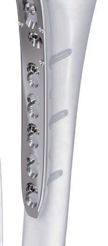
4 VA-LCP Proximal Tibial Plate 3.5. Part of the Synthes Variable Angle Periarticular Plating System. The Variable Angle LCP Proximal Tibial Plate 3.5 is part of the VA-LCP Periarticular Plating System, which combines variable angle locking screw technology with conventional plating techniques. Kirschner wire and suture holes Variable angle (VA) locking technology Four columns of threads in the VA locking holes provide a fixed-angle construct at the desired screw angle. VA locking holes allow +/- 15 off-axis screw angulation in order to: Adapt screw trajectory to varying tibial plateau inclinations, thereby avoiding joint penetration Adapt screw trajectory to condyle size by distributing screws over the tibial plateau Capture fracture fragments and target specific anatomic regions Anchor screws in good quality bone Avoid collisions with other implants or prostheses VA locking holes Long compression hole Color-coded VA locking screw heads for differentiation from locking screws VA locking combi-holes Anatomically precontoured plates may improve plateto-bone fit which reduces the risk of soft tissue irritation VA locking combi-holes in the plate shaft combine compression and VA locking capabilities 1 DePuy Synthes VA-LCP Proximal Tibial Plate 3.5 Surgical Technique

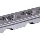
 Simple set configurations Small Bend Large Bend Surgical Technique VA-LCP Proximal Tibial Plate 3.")
5 Plates Available in small and large bend to cover a wide range of tibial shapes Available in 4 to 14 holes ranging from 87 mm to 237 mm to cover both tibial plateau and associated metaphyseal and diaphyseal fractures Instrumentation Instrumentation for straight forward assembly and i mproved handling Aiming arm for minimally-invasive screw insertion suitable for all plate types (right, left, small bend, large bend) Simple set configurations Small Bend Large Bend Surgical Technique VA-LCP Proximal Tibial Plate 3.5 DePuy Synthes 3

6 AO Principles AO PRINCIPLES In 1958, the AO formulated four basic principles, which have In 1958, become the AO the formulated guidelines four for internal basic principles, fixation 1,2 which. have become the guidelines for internal fixation 1, 2. 4_Priciples_03.pdf :08 Anatomic reduction Fracture reduction and fixation to restore restore anatomical relationships. relationships. 1 2 Stable fixation Fracture fixation providing absolute or relative or relative stability, stability, as required as absolute required by the patient, by the patient, the injury, the and injury, the and personality the personality of the fracture. of the fracture. Early, active mobilization Early and safe mobilization and rehabilitation of the injured part and the patient as a whole. 4 3 Preservation of blood supply Preservation of the blood supply to soft tissues and bone by gentle gentle reduction reduction techniques techniques and careful and careful handling. handling. 1 Müller ME, M Allgöwer, R Schneider, H Willenegger. Manual of Internal Fixation. 3rd ed. Berlin Heidelberg New York: Springer Rüedi TP, RE Buckley, CG Moran. AO Principles of Fracture Management. 2nd ed. Stuttgart, New York: Thieme Müller ME, Allgöwer M, Schneider R, Willenegger H. Manual of Internal Fixation. 3 rd ed. Berlin, Heidelberg, New York: Springer Rüedi TP, Buckley RE, Moran CG. AO Principles of Fracture Management. 2 nd ed. Stuttgart, New York: Thieme DePuy Synthes Expert VA-LCP Lateral Proximal Femoral Tibial Nail Plate Surgical 3.5 Surgical Technique Technique


7 Indications and Contraindications Indications Fractures of the proximal tibia in adults and adolescents with closed growth plates including Proximal split, depression or split-depression f r a c t u r e s Bicondylar or pure metaphyseal fractures Associated metaphyseal or associated shaft f r a c t u r e s Periprosthetic fractures Contraindications No specific contraindications. Surgical Technique VA-LCP Proximal Tibial Plate 3.5 DePuy Synthes 5
8 Preparation 1. Preparation Required sets VA-LCP Proximal Tibial Plates 3.5, Stainless Steel VA Instruments and Long Screw Insertion Instruments Aiming Arm Instruments for VA-LCP Proximal Tibial Plates 3.5 VA Locking Screws B 3.5 mm Optional sets Screw Insertion Instruments 3.5/4.0, in Modular Tray, Vario Case System Extraction Set for Standard Screws Reduction Instruments Cortex Screws B 3.5 mm Complete the preoperative radiographic assessment and prepare the preoperative plan. Use the VA-LCP Proximal Tibial Plate 3.5 x-ray template ( for right and for left) for estimation of implant size. Note: Preoperative planning of lag screws may be necessary. Note: In case of (associated) shaft fractures, it is essential to insert four screws per fragment. Be sure to choose a plate of appropriate length to incorporate these screws. Note: For information on fixation principles using conventional and locked plating techniques, please refer to the Synthes LCP Locking Compression Plate surgical technique: DSEM/TRM/0115/ DePuy Synthes VA-LCP Proximal Tibial Plate 3.5 Surgical Technique

9 2. Patient positioning Position the patient supine on a radiolucent operating table. The leg should be freely movable. The contralateral leg can be placed in an obstetric leg holder. Visualization of the proximal tibia under fluoroscopy in both the lateral and AP views is necessary. Support the knee with towels to flex it into the appropriate position. Alternatively, the thigh can be placed and fixed in a leg holder in flexion. Surgical Technique VA-LCP Proximal Tibial Plate 3.5 DePuy Synthes 7


10 Preparation 3. Surgical approach Depending on requirements, perform either a curved (120 hockey stick) or a straight skin incision from Gerdy s tubercle about 50 mm in a distal direction. Approximately half a centimeter from the tibial ridge, detach the anterior tibial muscle from the bone and retract it. The plate will be inserted in the space between the periosteum and the muscle. To allow correct positioning of the proximal part of the plate, it is important to adequately dissect the muscle attachment site. For complex intra-articular fractures, an anterolateral arthrotomy that provides good control of the reduction may be preferred. The arthrotomy is performed underneath and parallel to the lateral meniscus. The meniscus is fixed and secured with resorbable retention stitches. 8 DePuy Synthes VA-LCP Proximal Tibial Plate 3.5 Surgical Technique

11 Plate Insertion and Fixation 1. Determine plate type Instruments Trial Implant for VA-LCP Proximal Tibial Plate 3.5, Small Bend, right, with 6 marked holes Trial Implant for VA-LCP Proximal Tibial Plate 3.5, Small Bend, left, with 6 marked holes Trial Implant for VA-LCP ProximalTibial Plate 3.5, Large Bend, right, with 6 marked holes Trial Implant for VA-LCP ProximalTibial Plate 3.5, Large Bend, left, with 6 marked holes Use the trial implant for the correct side to determine the plate type (small bend/large bend) fitting best to the patient s anatomy. The trial implants are marked with SB and LB for differentiation. Note: Take into consideration that the fractured bone might be broadened and lead to the identification of the wrong plate type. In this case, x-ray images of the other limb may be useful for comparison. Surgical Technique VA-LCP Proximal Tibial Plate 3.5 DePuy Synthes 9

12 Plate Insertion and Fixation 2. Prepare aiming arm instruments Instruments Nut for Cannulated Interlocking Bolt Cannulated Interlocking Bolt 1.6 mm or Cannulated Interlocking Bolt 2.8 mm Insertion Handle for Aiming Arm for VA-LCP Proximal Tibial Plate 3.5, right or Insertion Handle for Aiming Arm for VA-LCP Proximal Tibial Plate 3.5, left Aiming Arm for VA-LCP Proximal Tibial Plate Combination Wrench B 11.0 mm Note: In certain cases (e.g. proximal fracture treated with a short plate) it may be advantageous to do the surgery without using an aiming arm. Then for inserting VA locking screws in the plate shaft the same surgical technique as des-cribed in the section Screw Insertion in the Plate Head applies. Accordingly Cortex screws can be inserted in the shaft of the plate without using the aiming arm by applying the technique described in chapter 4 of the section Plate Insertion and Fixation. Thread the nut onto a cannulated interlocking bolt. Choose between a bolt with cannulation 1.6 mm to insert a guide wire for preliminary fixation and a bolt with cannulation 2.8 mm to predrill the distal neck hole. 12 DePuy Synthes VA-LCP Proximal Tibial Plate 3.5 Surgical Technique


13 Choose the appropriate plate length, side and version (small/large bend) and place it on a flat surface to allow the correct assembly of the insertion handle and plate. Note: The VA-LCP Proximal Tibial Plates are anatomically precontoured. Plate bending is not recommended. If the plate contour is changed, the aiming arm may not properly target the holes in the plate. Position the insertion handle on the plate so that the pins on the underside of the insertion handle align with the three dimples around the distal neck hole. The flats on the side of the insertion handle help to mount the insertion handle in the correct orientation. Surgical Technique VA-LCP Proximal Tibial Plate 3.5 DePuy Synthes 11

.")
14 Plate Insertion and Fixation Insert the assembled interlocking bolt with nut into the insertion handle and thread it into the plate until tight. If the Allen key is used to tighten the bolt, make sure not to damage the hole. Tighten the nut with the combination wrench. Thread the connection screw into the correct side of the aiming arm and attach the aiming arm to the insertion handle. Use the combination wrench to secure the connection screw and aiming arm to the insertion handle. Note: The aiming arm can be used for all plate types (left, right, small bend, large bend). Be sure to attach the aiming arm in the correct orientation by checking the marked side on the top and side part of the aiming arm. Confirm side: right/left 11 DePuy Synthes VA-LCP Proximal Tibial Plate 3.5 Surgical Technique

15 3. Insert and preliminarily fix plate Instruments Kirschner Wire B 2.0 mm with trocar tip, length 150 mm, Stainless Steel Universal Drill Guide Drill Bit B 2.5 mm with Stop, calibrated, length 250/225 mm, for Quick Coupling Depth Gauge for Long Screws B 3.5 mm, measuring range up to 110 mm Screwdriver Shaft, hexagonal, small, B 2.5 mm, length 165 mm, for Quick Coupling Handle with Quick Coupling, length 150 mm Using the aiming arm assembly, insert the plate between the anterior tibial muscle and the periosteum. Slide the plate in the distal direction with its distal end in constant contact with the bone. Carefully find the correct position of the plate on the condyle and the correct position of the distal part of the plate, either with an image intensifier or by direct palpation. Note: The aiming arm can be attached either before or after insertion of the plate. Precautions: Instruments and screws may have sharp edges or moving joints that may pinch or tear user s glove or skin. Handle devices with care and dispose worn bone cutting instruments in an approved sharps container. Surgical Technique VA-LCP Proximal Tibial Plate 3.5 DePuy Synthes 11

16 Plate Insertion and Fixation Insert Kirschner wires B 2.0 mm through the Kirschner wire holes either in the proximal or in the middle part of the plate head to fix the plate to the bone. Preliminarily secure the plate with a cortex screw through the long hole in the neck of the plate. Insert the drill bit B 2.5 mm into the universal drill guide and advance it until it reaches the medial cortex. 11 DePuy Synthes VA-LCP Proximal Tibial Plate 3.5 Surgical Technique


17 Remove the drill bit and drill guide and use the depth gauge to measure for screw length. Note: Do not use the drill bit calibration for screw measurement. Optional instruments Tap for Cortex Screws B 3.5 mm, calibrated, length 175 mm Handle with Quick Coupling, length 150 mm For non-self-tapping cortex screws connect the long tap to the handle and tap the thread. Insert the correct length cortex screw with the power tool using the hexagonal screwdriver shaft. For final tightening, assemble the screwdriver shaft to the handle and tighten the screw. The long hole can assist in reducing lateral split fractures: tightening the cortex screw in the plate will compress the fragment to the bone (buttressing effect). Tighten screw Fracture gap closes Surgical Technique VA-LCP Proximal Tibial Plate 3.5 DePuy Synthes 11
18 Plate Insertion and Fixation Note: To avoid screw collision of the cortex screw in the long hole and the locking screw in the distal neck hole, insert a long drill guide to check the trajectory. When using an aiming arm, a Kirschner wire B 1.6 mm can be inserted through the insertion handle. At this point in time adaptations of the plate position can still be done. Precaution: Proper plate position is key to success: a plate positioned too distally does not provide adequate rafting support of the articular surface; a plate positioned too proximally may damage the joint area with the proximal screws. 11 DePuy Synthes VA-LCP Proximal Tibial Plate 3.5 Surgical Technique

19 4. Reduce articular surface Instruments Universal Drill Guide Drill Bit B 2.5 mm with Stop, calibrated, length 250/225 mm, for Quick Coupling Depth Gauge for Long Screws B 3.5 mm, measuring range up to 110 mm Screwdriver Shaft, hexagonal, small, B 2.5 mm, length 165 mm, for Quick Coupling Handle with Quick Coupling, length 150 mm Fracture reduction is usually done over the plate as the space for independent screws in the tibial condyle is usually restricted. However, fracture reduction can also be achieved by inserting independent compression screws in the zone proximal to the plate. Make sure that these screws neither collide with the locking screws of the plate nor penetrate the joint area. In case of a split fracture, the lateral condyle has to be compressed with an interfragmentary cortex screw to fix the previously secured fragment. Note: Make sure to insert enough VA locking screws to guarantee full construct stability. Insert the drill bit B 2.5 mm into the universal drill guide and advance it until it slightly penetrates the medial c o r t e x. Remove the drill bit and drill guide and use the depth gauge to measure for screw length. Surgical Technique VA-LCP Proximal Tibial Plate 3.5 DePuy Synthes 11
20 Plate Insertion and Fixation Optional instrument Tap for Cortex Screws B 3.5 mm, calibrated, length 175 mm For non-self-tapping cortex screws, use the long tap to tap the thread. Insert the correct length cortex screw with the power tool using the hexagonal screwdriver shaft. For final tightening, assemble the screwdriver shaft to the handle and tighten the screw. Before proceeding, use clinical examination and fluoroscopy to confirm that: the plate is orientated properly on the tibial plateau. screw trajectories in the proximal locking holes are parallel to the joint in the transverse plane. the alignment of the plate to the shaft of the tibia is correct in both the AP and lateral views. At this point of the surgery the wires for preliminary fixation can be taken out. Note: In depressed tibial plateau fractures, the use of bone void fillers to support the plateau surface may be beneficial. 11 DePuy Synthes VA-LCP Proximal Tibial Plate 3.5 Surgical Technique


21 5. Secure aiming arm to plate distally Instruments Trocar with Handle B 6.0 mm Guide Sleeve for Aiming Arm Instruments for VA Plates Centering Sleeve, percutaneous, for Kirschner Wire B 1.6 mm Kirschner Wire B 1.6 mm, with drill tip, length 200 mm, Cobalt Chrome Alloy Combination Wrench B 11.0 mm Allen Key, small, B 2.5 mm, angled Use the combination wrench and Allen key to make sure that all connections between aiming arm, insertion handle and plate are still fully tightened. To avoid screw hole damage or disassembly problems, make sure not to tighten any connection excessively. To avoid undesirable movement in the aiming arm system, the aiming arm must be secured distally to the plate and bone. Locate the hole in the aiming arm that corresponds to the most distal combi-hole in the plate. The numbering on the aiming arm indicates the hole location on the plate. Make a skin incision at this location. Surgical Technique VA-LCP Proximal Tibial Plate 3.5 DePuy Synthes 11
22 Plate Insertion and Fixation Notes: When using a plate with more than 12 holes, perform a careful soft tissue dissection down to the plate before inserting the trocar and guide sleeve in order to visualize and protect the superficial peroneal nerve and anterior neurovascular bundle. In patients of short stature the critical area may be reached with a shorter plate. Optional instrument Scalpel for Percutaneous Aiming Arm Instruments Attach a blade to the scalpel handle. The scalpel handle will pass through the aiming arm holes and assist in performing an accurate and minimally invasive incision. The scalpel handle should be inserted, backed out, rotated 180, and reinserted. An adequate incision must be made to avoid soft tissue impingement when inserting a drill guide or wire guide. Then remove the scalpel from the aiming arm. Note: Always remove the scalpel blade before storage in the case. 22 DePuy Synthes VA-LCP Proximal Tibial Plate 3.5 Surgical Technique

23 Assemble the trocar with handle with a guide sleeve. Orient the arrow on the guide sleeve in the direction of the LOCKING SCREW arrow on the aiming arm. Use the assembled trocar and guide sleeve to push down to the plate through the incision. Push the assembly down until it snaps completely into the aiming arm. Make sure not to place excessive pressure on the guide sleeve as deflection can occur between the guide sleeve and the plate. Remove the trocar. Insert the percutaneous centering sleeve into the guide sleeve and securely thread it into the most distal plate hole. Optional instrument Handle for Drill Sleeves with thread A handle can be attached to the centering sleeve to facilitate insertion. Turn the handle counterclockwise to disengage and remove it from the guide sleeve. Insert a Kirschner wire B 1.6 mm through the centering sleeve into the bone after the appropriate plate position has been found. Alternative instruments Locking Drill Sleeve B 2.8 mm, percutaneous Drill Bit B 2.8 mm with Stop, calibrated, length 250/225 mm, for Quick Coupling Surgical Technique VA-LCP Proximal Tibial Plate 3.5 DePuy Synthes 22
24 Plate Insertion and Fixation Alternatively, a locking drill sleeve and a drill bit can be used to stabilize the distal portion of the plate on the bone. Use the drill bit B 2.8 mm to drill through the locking drill sleeve to the far cortex. Notes: After closing the aiming arm frame distally, the range of eccentric compression is limited. For clear visualization, soft tissue is not shown in the following steps. Tighten all connections before proceeding. 22 DePuy Synthes VA-LCP Proximal Tibial Plate 3.5 Surgical Technique
25 6. Use pull reduction device Instruments Guide Sleeve for Aiming Arm Instruments for VA Plates Pull Reduction Device for Outer Sleeve, for LCP Percutaneous Aiming Instruments 3.5* Combination Wrench B 11.0 mm The insertion of the first screw in the plate shaft may push the bone medially, especially in case of dense bone and/or unstable reduction. The pull reduction device helps to solve this problem. Alternatively, a cortex screw can be used. The pull reduction device must be used with a guide sleeve and in the locking portion of the plate. Orient the arrow on the guide sleeve in the direction of the LOCK- ING SCREW arrow on the aiming arm. Thread the nut for the pull reduction device over the tip of the pull reduction device. * The nut is included in and can be reordered under (Nut for Pull Reduction Device). Surgical Technique VA-LCP Proximal Tibial Plate 3.5 DePuy Synthes 22
26 Plate Insertion and Fixation With the nut in its highest position, attach the pull reduction device to a power tool with quick coupling and insert it through a guide sleeve. Note: When inserting the pull reduction device, carefully monitor the advance of the tip. Remove the power tool and begin tightening the nut toward the drill guide while monitoring progress under radiographic imaging. This will pull the bone towards the plate and fix it in that position. Note: A combination wrench may be used to facilitate tightening and loosening of the nut. Stop when the desired reduction is achieved. Do not tighten the nut excessively. Note: The predrilled hole allows the later placement of a VA locking screw B 3.5 mm in the same hole. 22 DePuy Synthes VA-LCP Proximal Tibial Plate 3.5 Surgical Technique


27 Screw Insertion in the Plate Head 1. Insert VA locking screws B 3.5 mm in proximal row Option A. Insert VA locking screws in fixed angle (non-angled position) Instruments VA Fixed Angle Drill Guide 3.5, for Drill Bits 2.8 mm Drill Bit B 2.8 mm, with Scale, length 200/100 mm, 3-flute, for Quick Coupling Handle with Torque Limiting Function, 2.5 Nm Screwdriver Shaft 3.5 Stardrive, T15, long, self-holding, for AO/ASIF Quick Coupling Insert the VA fixed angle drill guide into a plate hole of the proximal rafting row. The drill guide is designed to be inserted into the plate to avoid an incorrect angle when threading it in. Drill through the drill guide using the drill bit B 2.8 mm. The four proximal rafting screws should be placed both parallel to the joint axis and parallel to each other. Advance the drill bit until it reaches the medial wall of the tibial condyle. Note: Monitor the direction of the drill bit carefully when drilling. Although the fixed angle drill guide limits the range of motion, a completely fixed angle cannot be guaranteed. Precaution: Make sure not to penetrate the articular surface (even in zero position a penetration is possible in unusual tibial plateau inclinations) or to cause screw collision. Furthermore, to avoid degeneration of the overlying articular cartilage, do not place screws too close to the tibial plateau. Surgical Technique VA-LCP Proximal Tibial Plate 3.5 DePuy Synthes 22
28 Screw Insertion in the Plate Head Read the measurement from the calibrated drill bit B 2.8 mm. Remove the drill bit and drill guide. Insert the appropriate length VA locking screw. The VA locking screw B 3.5 mm may be inserted using a power tool and the screwdriver shaft Stardrive T15. Final tightening must be done by hand using the screwdriver shaft Stardrive T15 together with the handle with torque limiting function 2.5 Nm. Note: Confirm screw position and length prior to final tightening with the handle with torque limiting function 2.5 Nm. 22 DePuy Synthes VA-LCP Proximal Tibial Plate 3.5 Surgical Technique
29 Alternative instrument VA Double Drill Guide 3.5, for Drill Bits B 2.8 mm Alternatively, the straight end of the VA double drill guide may be used for predrilling. The VA double drill guide allows either off-axis drilling (funnel end) or fixed angle drilling (straight end). Note: Insert the fixed angle screws first, then insert the variable angle screws. Place the variable angle screws around the fixed angle screws. Repeat the steps above to insert additional screws. Surgical Technique VA-LCP Proximal Tibial Plate 3.5 DePuy Synthes 22


30 Screw Insertion in the Plate Head Option B. Insert VA locking screws in variable angle Instruments VA Double Drill Guide 3.5, for Drill Bits B 2.8 mm Drill Bit B 2.8 mm, with Scale, length 200/100 mm, 3-flute, for Quick Coupling Depth Gauge for Long Screws B 3.5 mm, measuring range up to 110 mm Handle with Torque Limiting Function, 2.5 Nm Screwdriver Shaft 3.5 Stardrive, T15, long, self-holding, for AO/ASIF Quick Coupling Insert the funnel-shaped end of the double drill guide into a plate hole of the proximal rafting row. The drill guide is designed to be inserted into the plate to avoid an incorrect angle when threading it in. Drill through the double drill guide at the desired angle using the drill bit B 2.8 mm. The four proximal rafting screws should be placed parallel to the joint axis. Their angle can be adapted to the tibial plateau inclination. Advance the drill bit until it reaches the medial wall of the tibial condyle. Note: Monitor the direction of the drill bit carefully when drilling. Precaution: Make sure not to penetrate the articular surface or to cause screw collision. Remove the drill bit and drill guide and use the depth gauge to measure for screw length. 22 DePuy Synthes VA-LCP Proximal Tibial Plate 3.5 Surgical Technique
31 Insert the appropriate length VA locking screw. The VA locking screw B 3.5 mm may be inserted using a power tool and the screwdriver shaft Stardrive T15. Final tightening must be done by hand using the screwdriver shaft Stardrive T15 together with the handle with torque limiting function 2.5 Nm. Note: Confirm screw position and length prior to final tightening with the handle with torque limiting function 2.5 Nm. Repeat the steps above to insert additional screws. Surgical Technique VA-LCP Proximal Tibial Plate 3.5 DePuy Synthes 22
32 Screw Insertion in the Plate Head 2. Insert VA locking screws B 3.5 mm in second row Option A. Insert VA locking screws in fixed angle (non-angled position) Instruments VA Fixed Angle Drill Guide 3.5, for Drill Bits B 2.8 mm Drill Bit B 2.8 mm, with Scale, length 200/100 mm, 3-flute, for Quick Coupling Handle with Torque Limiting Function, 2.5 Nm Screwdriver Shaft 3.5 Stardrive, T15, long, self-holding, for AO/ASIF Quick Coupling To insert fixed angle VA locking screws in the second row, follow the procedure described in Step DePuy Synthes VA-LCP Proximal Tibial Plate 3.5 Surgical Technique


33 Option B. Insert VA locking screws in variable angle Instruments VA Double Drill Guide 3.5, for Drill Bits B 2.8 mm Drill Bit B 2.8 mm, with Scale, length 200/100 mm, 3-flute, for Quick Coupling Depth Gauge for Long Screws B 3.5 mm, measuring range up to 110 mm Handle with Torque Limiting Function, 2.5 Nm Screwdriver Shaft 3.5 Stardrive, T15, long, self-holding, for AO/ASIF Quick Coupling To insert fixed angle VA locking screws in the second row, follow the procedure described in Step 1. Note: Should some plate head holes be empty, ensure that the screws are distributed between the proximal and the second row rather than filling the proximal row only. Surgical Technique VA-LCP Proximal Tibial Plate 3.5 DePuy Synthes 33

34 Screw Insertion in the Plate Shaft 1. Insert cortex screws B 3.5 mm in plate shaft Instruments Guide Sleeve for Aiming Arm Instruments for VA Plates Trocar with Handle B 6.0 mm Drill Sleeve B 2.5 mm, for neutral position, percutaneous or Drill Sleeve B 2.5 mm, for compression position, percutaneous Drill Bit B 2.5 mm with Stop, calibrated, length 250/225 mm, for Quick Coupling Screwdriver Shaft, hexagonal, small, B 2.5 mm, length 165 mm, for Quick Coupling Handle with Quick Coupling, length 150 mm Choose an aiming arm hole through which to make an incision. Notes: When using a plate with more than 12 holes, perform a careful soft tissue dissection down to the plate before inserting the trocar and guide sleeve in order to visualize and protect the superficial peroneal nerve and anterior neurovascular bundle. In patients of short stature the critical area may be reached with a shorter plate. 33 DePuy Synthes VA-LCP Proximal Tibial Plate 3.5 Surgical Technique


35 Optional instrument Scalpel for Percutaneous Aiming Arm Instruments Optionally, the scalpel handle can be used. Attach a blade to the scalpel handle. The scalpel handle will pass through the aiming arm holes and assist in performing a minimally invasive and accurate incision. The scalpel handle should be inserted, backed out, rotated 180, and reinserted. An adequate incision must be made to avoid soft tissue impingement when inserting a drill guide or wire guide. Then remove the scalpel from the aiming arm. Note: Always remove the scalpel blade before storage in the case. Assemble the trocar with handle with a guide sleeve. Orient the arrow on the guide sleeve in the direction of the CORTEX SCREW arrow on the aiming arm. Use the assembled trocar and guide sleeve to push down to the plate through the incision. Push the assembly down until it snaps completely into the aiming arm. Remove the trocar. Surgical Technique VA-LCP Proximal Tibial Plate 3.5 DePuy Synthes 33


36 Screw Insertion in the Plate Shaft Choose an appropriate drill sleeve, either for neutral or load position, and insert it into the guide sleeve until it snaps securely into place. When positioning the drill sleeve, make sure that the open ends of the instruments are oriented towards the clamping mechanism of the guide sleeve. Note: When using the compression drill sleeve, it is important to insert the drill sleeve in the proper orientation into the guide sleeve as shown on the picture on the left. Note: After closing the aiming arm frame distally, the range of eccentric compression is limited. 33 DePuy Synthes VA-LCP Proximal Tibial Plate 3.5 Surgical Technique
.")

37 Use the drill bit B 2.5 mm with stop to drill to the desired depth. Verify that the plastic stop sits on the drill sleeve before removing the drill bit (1). Remove the drill bit and read the drill depth indicated below the plastic stop (2). The first visible number indicates the correct depth. Remove the drill sleeve by gently depressing its release mechanism and slowly pulling it away from the guide sleeve. 1 2 Surgical Technique VA-LCP Proximal Tibial Plate 3.5 DePuy Synthes 33


38 Screw Insertion in the Plate Shaft Alternative instrument Depth Gauge for Percutaneous Aiming Arm Instruments Alternatively, screw length can be determined with the help of the depth gauge. Remove the drill sleeve and insert the depth gauge into the guide sleeve to the previously drilled depth. The screw length is indicated by the gauge marking aligned with the top of the guide sleeve. Remove the depth gauge. Insert the appropriate length cortex screw. The cortex screw may be inserted using a power tool and the hexagonal screwdriver shaft. Switch to manual screw insertion using the screwdriver shaft with handle when the marking on the screwdriver shaft approaches the end of the guide sleeve. 33 DePuy Synthes VA-LCP Proximal Tibial Plate 3.5 Surgical Technique
39 Optional instrument Stopper for Aiming Arm, for VA Plates 3.5 Mark each screw location in the aiming arm using a stopper for reference as screw insertion proceeds. Repeat the steps above to insert additional screws. Note: All cortex screws B 3.5 mm must be inserted before inserting locking screws. Surgical Technique VA-LCP Proximal Tibial Plate 3.5 DePuy Synthes 33

40 Screw Insertion in the Plate Shaft 2. Insert VA locking screws B 3.5 mm in plate shaft Option A: Insert VA locking screws in fixed angle over aiming arm Instruments Guide Sleeve for Aiming Arm Instruments for VA Plates Trocar with Handle B 6.0 mm Locking Drill Sleeve B 2.8 mm, percutaneous Drill Bit B 2.8 mm with Stop, calibrated, length 250/225 mm, for Quick Coupling Screwdriver Shaft 3.5 Stardrive, T15, long, self-holding, for AO/ASIF Quick Coupling Handle with Torque Limiting Function, 2.5 Nm Allen Key, small, B 2.5 mm, angled Choose an aiming arm hole through which to make an incision and create the incision. Optionally, the scalpel handle can be used. Notes: When using a plate with more than 12 holes, perform a careful soft tissue dissection down to the plate before inserting the trocar and guide sleeve in order to visualize and protect the superficial peroneal nerve and anterior neurovascular bundle. In patients of short stature the critical area may be reached with a shorter plate. 33 DePuy Synthes VA-LCP Proximal Tibial Plate 3.5 Surgical Technique

.")
41 Assemble the trocar with handle with a guide sleeve. Orient the arrow on the guide sleeve in the direction of the LOCKING SCREW arrow on the aiming arm. Use the assembled trocar and guide sleeve to push down to the plate through the incision. Push the assembly down until it snaps completely into the aiming arm. Remove the trocar. Insert the locking drill sleeve into the guide sleeve and securely thread it into the plate. To facilitate the insertion, the handle can be used. Use the calibrated drill bit B 2.8 mm with stop to drill to the desired depth. Verify that the plastic stop sits on the drill sleeve before removing the drill bit (1). Remove the drill bit and read the indicated drill depth below the plastic stop (2). The first number visible indicates the correct depth. Alternatively, screw length can be determined with the help of the depth gauge (see page 36). 1 2 Surgical Technique VA-LCP Proximal Tibial Plate 3.5 DePuy Synthes 33

42 Screw Insertion in the Plate Shaft Insert the appropriate length VA locking screw. The VA locking screw B 3.5 mm may be inserted using a power tool and the screwdriver shaft Stardrive T15. Final tightening must be done by hand using the screwdriver shaft Stardrive T15 together with the handle with torque limiting function 2.5 Nm. Switch to manual screw insertion when the marking on the screwdriver shaft approaches the end of the guide sleeve. Note: Confirm screw position and length prior to final tightening with the handle with torque limiting function 2.5 Nm. Mark each screw location in the aiming arm using a stopper for reference as screw insertion proceeds. Repeat the steps above to insert additional screws. Note: Use the Allen key to loosen the locking drill sleeve from the plate. 44 DePuy Synthes VA-LCP Proximal Tibial Plate 3.5 Surgical Technique
43 Option B: Insert VA locking screws in variable angle over freehand drill guide Trocar Instruments VA Drill Guide 3.5, for Drill Bits B 2.8 mm, long, with spherical head Trocar for VA Drill Guide 3.5, for Drill Bits B 2.8 mm, long, with spherical head Protection Sleeve for VA Drill Guide 3.5, for Drill Bits B 2.8 mm, long, with spherical head Drill Bit B 2.8 mm with Stop, calibrated, length 250/225 mm, for Quick Coupling VA drill guide with spherical head Protection sleeve Screwdriver Shaft 3.5 Stardrive, T15, long, self-holding, for AO/ASIF Quick Coupling Handle with Torque Limiting Function, 2.5 Nm Assemble the freehand drill guide: thread the VA drill guide into the protection sleeve and insert the trocar into the VA drill guide. Surgical Technique VA-LCP Proximal Tibial Plate 3.5 DePuy Synthes 44


44 Screw Insertion in the Plate Shaft Depending on the desired angle, the trocar/drill guide/ protection sleeve assembly may be placed through the aiming arm hole, or it may be placed outside of the aiming arm. The aiming arm helps to locate the hole. Choose an aiming arm hole through which to make an incision. When using the instrument outside of the aiming arm, it may be necessary to extend the cut. Notes: When using a plate with more than 12 holes, perform a careful soft tissue dissection down to the plate before inserting the trocar and guide sleeve in order to visualize and protect the superficial peroneal nerve and anterior neurovascular bundle. In patients of short stature the critical area may be reached with a shorter plate. Insert the assembly to the plate through the previously created incision. The spherical tip of the VA drill guide should be gently pressed into the variable angle hole to prevent drilling beyond 15. Remove the trocar from the assembly. 1 2 Use the calibrated drill bit B 2.8 mm with stop to drill to the desired depth. Verify that the plastic stop sits on the drill guide. Remove the drill bit and read the indicated drill depth below the plastic stop as described in Option A. Note: The long drill bit B 2.8 mm is calibrated for the VA Drill Guide 3.5 ( ) and for the percutaneous Locking Drill Sleeve ( ). 44 DePuy Synthes VA-LCP Proximal Tibial Plate 3.5 Surgical Technique


45 Remove the drill bit and prepare the appropriate length VA locking screw. Carefully remove the drill guide and make sure that the protection sleeve remains in the proper position above the screw hole. Insert the screw through the protection sleeve. The VA locking screw B 3.5 mm may be inserted using a power tool and the screwdriver shaft Stardrive T15. Final tightening must be done by hand using the screwdriver shaft Stardrive T15 together with the handle with torque limiting function 2.5 Nm. Note: Confirm screw position and length prior to final tightening with the handle with torque limiting function 2.5 Nm. Repeat the steps above to insert additional screws. Surgical Technique VA-LCP Proximal Tibial Plate 3.5 DePuy Synthes 44

46 Screw Insertion in the Plate Neck 1. Aiming arm removal Instruments Allen Key, small, B 2.5 mm, angled Combination Wrench B 11.0 mm In case an aiming arm has been used, detach it from the plate before predrilling the angled holes in the plate neck. Alternative instruments Cannulated Interlocking Bolt 2.8 mm Drill Bit B 2.8 mm with Stop, calibrated, length 250/225 mm, for Quick Coupling Alternatively, predrilling can be done with the long drill bit with stop through the cannulated interlocking bolt still connected to the insertion handle and plate. The required length can be read off the drill bit calibration below the plastic stop. 44 DePuy Synthes VA-LCP Proximal Tibial Plate 3.5 Surgical Technique

47 Remove all aiming arm instruments prior to screw i n s e r t i o n. To remove the aiming arm, remove all guide sleeves, drill sleeves and the pull reduction device. Turn the connecting bolt on the aiming arm counterclockwise to loosen it and remove the aiming arm from the insertion handle. Turn the interlocking nut and then the interlocking bolt counterclockwise and remove the interlocking bolt with nut and the insertion handle. Note: Use the Allen key to loosen locking drill sleeves, centering sleeves and the interlocking bolt. Use the combination wrench to loosen the connection bolt of the aiming arm and the nut on the interlocking bolt. Surgical Technique VA-LCP Proximal Tibial Plate 3.5 DePuy Synthes 44


48 Screw Insertion in the Plate Neck 2. Insert VA locking screw B 3.5 mm in distal neck hole Instruments VA Fixed Angle Drill Guide 3.5, for Drill Bits B 2.8 mm Drill Bit B 2.8 mm, with Scale, length 200/100 mm, 3-flute, for Quick Coupling Handle with Torque Limiting Function, 2.5 Nm Screwdriver Shaft 3.5 Stardrive, T15, long, self-holding, for AO/ASIF Quick Coupling Drill through the drill guide using the drill bit B 2.8 mm. Advance the drill bit until it reaches the medial wall of the tibial condyle. Note: Monitor the direction of the drill bit carefully when drilling. Although the fixed angle drill guide limits the range of motion a completely fixed angle cannot be guaranteed. Precaution: Make sure not to cause screw collision, especially if the second row screws have been angled away from the nominal axis. Alternative Instrument VA Double Drill Guide 3.5, for Drill Bits B 2.8 mm Alternatively, the VA double drill guide may be used for predrilling in fixed or variablee angle position. Read the measurement from the calibrated drill bit B 2.8 mm. Remove the drill bit and drill guide. 46 DePuy Synthes VA-LCP Proximal Tibial Plate 3.5 Surgical Technique
49 Insert the appropriate length VA locking screw. The VA locking screw B 3.5 mm may be inserted using a power tool and the screwdriver shaft Stardrive T15. Final tightening must be done by hand using the screwdriver shaft Stardrive T15 together with the handle with torque limiting function 2.5 Nm. Note: Confirm screw position and length prior to final tightening with the handle with torque limiting function 2.5 Nm. Surgical Technique VA-LCP Proximal Tibial Plate 3.5 DePuy Synthes 47


50 Screw Insertion in the Plate Neck 3. Insert VA locking screw B 3.5 mm in proximal neck hole Instruments VA Fixed Angle Drill Guide 3.5, for Drill Bits B 2.8 mm Drill Bit B 2.8 mm, with Scale, length 200/100 mm, 3-flute, for Quick Coupling Handle with Torque Limiting Function, 2.5 Nm Screwdriver Shaft 3.5 Stardrive, T15, long, self-holding, for AO/ASIF Quick Coupling 44 DePuy Synthes VA-LCP Proximal Tibial Plate 3.5 Surgical Technique

51 Insert a VA fixed angle drill guide into the proximal neck hole and follow the procedure described in Step 1. Alternatively, the VA double drill guide may be used for predrilling in fixed or variable angle position. Precaution: Make sure not to cause screw collision, especially if the proximal row screws have been angled away from the nominal axis. Surgical Technique VA-LCP Proximal Tibial Plate 3.5 DePuy Synthes 44
52 Closure Reattach the lateral meniscus either to the remaining rim of the capsule or to the most proximal small holes in the plate and perform wound closure. In general, to facilitate screw removal at a later stage, please include the type of screws recess used in the surgery report. 55 DePuy Synthes VA-LCP Proximal Tibial Plate 3.5 Surgical Technique
53 Implant Removal 1. Removal technique In case the physician decides to remove the implants, they can be removed by using general surgical instruments. Remove the implant only after complete consolidation of the fracture. Remove in reverse order to the implantation. First, make the incision in the path of the old scar. If an aiming arm was used, assemble the insertion handle and aiming arm with the plate. Make stab incisions and use the screwdriver shaft with the corresponding recess together with the handle with quick coupling ( ) to unlock all screws manually. In a second step, completely remove all screws with a power tool. Notes: When using a plate with more than 12 holes, perform a careful soft tissue dissection down to the plate before inserting the trocar and guide sleeve in order to visualize and protect the superficial peroneal nerve and anterior neurovascular bundle. In patients of short stature the critical area may be reached with a shorter plate. Surgical Technique VA-LCP Proximal Tibial Plate 3.5 DePuy Synthes 55

 General instruments for screw removal that can be used for all screw sizes Modular instrument trays for customized solutions For details regarding")
54 Implant Removal 2. Tips for removal Screw Extraction Set Screw Extraction Set. Instruments for removing Synthes screws Extraction Set for Standard Screws Handling Technique The Synthes screw extraction set contains the instruments required for removing intact screws or damaged screws that are difficult to remove. The set includes: Screw-size-related extraction instruments (e.g. screwdriver shafts, conical extraction screws) General instruments for screw removal that can be used for all screw sizes Modular instrument trays for customized solutions For details regarding implant removal refer to the surgical technique Screw Extraction Set DSEM/TRM/0614/0104. Stardrive A Stardrive recess facilitates screw insertion and extraction: High torque transmission between screwdriver and screw recess even with half the insertion depth (e.g. in cases of soft-tissue ingrowth) Reduced screw recess deformation as prerequisite for successful screw extraction Improved instrument durability and higher resistance to corrosion Specific screwdriver designs suited for insertion (conical design, self-holding) and extraction (cylindrical design, rounded tip to locate the recess easily and to allow a maximum of torque transmission) Facilitates screw insertion and extraction Why Stardrive? Synthes Stardrive locking, variable angle locking and cortex screws. For details regarding Stardrive Recess refer to the flyer Why stardrive DSEM/TRM/0115/ DePuy Synthes VA-LCP Proximal Tibial Plate 3.5 Surgical Technique
55 Care and Maintenance 1. Recalibration of the Torque Limiting Handle A product-specific Instruction for Use (IFU) has been created for the Handle with Torque Limiting Function, 2.5 Nm ( ). It includes all information regarding usage, recalibration, care and maintenance and is included in each package. Ensure to recalibrate the instrument as frequent as recommended (see SE_ for further details). 2. General information regarding cleaning and sterilization For details regarding cleaning and sterilization, please consult the following page: Surgical Technique VA-LCP Proximal Tibial Plate 3.5 DePuy Synthes 55
56 Plates Small bend plates Stainless Holes Length Side Steel (mm) right left right left right left right left right left right left All plates are available sterile packed. For sterile implants add suffix S to article number. 54 DePuy Synthes VA-LCP Proximal Tibial Plate 3.5 Surgical Technique
57 Large bend plates Stainless Holes Length Side Steel (mm) right left right left right left right left right left right left All plates are available sterile packed. For sterile implants add suffix S to article number. Surgical Technique VA-LCP Proximal Tibial Plate 3.5 DePuy Synthes 55
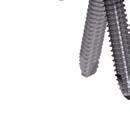
58 Screws VA Locking Screw Stardrive B 3.5 mm May be used in all variable angle locking holes including the locking portion of the combi-holes. Threaded rounded head Self-tapping tip Stardrive recess Lengths mm Stainless Steel The following existing screws are compatible with the VA-LCP Proximal Tibial Plate 3.5: Locking screw B 3.5 mm Cortex screw B 3.5 mm Locking Screw B 3.5 mm Note: Locking screws B 3.5 mm must be inserted at zero degrees and must be tightened with 1.5 Nm Torque Limiter Attachment. Note: It is recommended to use available guiding tools to assist insertion at zero degrees. Threaded conical head Self-tapping tip Cortex Screw B 3.5 mm May be used in the DCU portion of the VA locking combi- holes, in the long hole in the plate neck and in the plate head through a VA locking hole to create compression. Self-tapping tip Hexagonal recess Lengths mm 56 DePuy Synthes VA-LCP Proximal Tibial Plate 3.5 Surgical Technique

59 Instruments VA-Instruments VA Fixed Angle Drill Guide 3.5, for Drill Bits B 2.8 mm VA Double Drill Guide 3.5, for Drill Bits B 2.8 mm VA Drill Guide 3.5, for Drill Bits B 2.8 mm, long, with spherical head Trocar for VA Drill Guide 3.5, for Drill Bits B 2.8 mm, long, with spherical head Protection Sleeve for VA Drill Guide 3.5, for Drill Bits B 2.8 mm, long, with spherical head Surgical Technique VA-LCP Proximal Tibial Plate 3.5 DePuy Synthes 57


60 Instruments Trial Implant for VA-LCP Proximal Tibial Plate 3.5, Small Bend, right, with 6 marked holes Trial Implant for VA-LCP Proximal Tibial Plate 3.5, Small Bend, left, with 6 marked holes Trial Implant for VA-LCP Proximal Tibial Plate 3.5, Large Bend, right, with 6 marked holes Trial Implant for VA-LCP Proximal Tibial Plate 3.5, Large Bend, left, with 6 marked holes Handle with Torque Limiting Function, 2.5 Nm 58 DePuy Synthes VA-LCP Proximal Tibial Plate 3.5 Surgical Technique
61 Kirschner Wire B 2.0 mm with trocar tip, length 150 mm, Stainless Steel (also available in a pack of 10 pieces: ) Depth Gauge for Long Screws B 3.5 mm, measuring range up to 110 mm Drill Bit B 2.8 mm, with Scale, length 200/100 mm, 3-flute, for Quick Coupling Drill Bit B 2.5 mm with Stop, calibrated, length 250/225 mm, for Quick Coupling Drill Bit B 2.8 mm with Stop, calibrated, length 250/225 mm, for Quick Coupling Surgical Technique VA-LCP Proximal Tibial Plate 3.5 DePuy Synthes 59


62 Instruments Screwdriver Shaft 3.5 Stardrive, T15, long, self-holding, for AO/ASIF Quick Coupling Screwdriver Shaft, hexagonal, small, B 2.5 mm, length 165 mm, for Quick Coupling Handle with Quick Coupling, length 150 mm Universal Drill Guide Tap for Cortex Screws B 3.5 mm, calibrated, length 175 mm 62 DePuy Synthes VA-LCP Proximal Tibial Plate 3.5 Surgical Technique

63 Aiming Arm Instruments Insertion Handle for Aiming Arm for VA-LCP Proximal Tibial Plate 3.5, right Insertion Handle for Aiming Arm for VA-LCP Proximal Tibial Plate 3.5, left Aiming Arm for VA-LCP Proximal Tibial Plate Guide Sleeve for Aiming Arm Instruments for VA Plates Stopper for Aiming Arm, for VA Plates Nut for Cannulated Interlocking Bolt Cannulated Interlocking Bolt 1.6 mm Surgical Technique VA-LCP Proximal Tibial Plate 3.5 DePuy Synthes 61
64 Instruments Cannulated Interlocking Bolt 2.8 mm Kirschner Wire B 1.6 mm, with drill tip, length 200 mm, Cobalt Chrome Alloy Trocar with Handle B 6.0 mm Scalpel for Percutaneous Aiming Arm I n s t r u m e n t s Drill Sleeve B 2.5 mm, for neutral position, percutaneous Drill Sleeve B 2.5 mm, for compression position, percutaneous 61 DePuy Synthes VA-LCP Proximal Tibial Plate 3.5 Surgical Technique
 03.113.020 Locking Drill Sleeve B 2.8 mm, percutaneous 03.113.022 Centering Sleeve, percutaneous, for Kirschner Wire B 1.6 mm Surgical Technique VA-LCP Proximal Tibial Plate 3.")
65 Handle for Drill Sleeves with thread Pull Reduction Device for Outer Sleeve, for LCP Percutaneous Aiming Instruments Nut for Pull Reduction Device (This Spare part is integrated in ) Locking Drill Sleeve B 2.8 mm, percutaneous Centering Sleeve, percutaneous, for Kirschner Wire B 1.6 mm Surgical Technique VA-LCP Proximal Tibial Plate 3.5 DePuy Synthes 63
66 Instruments Depth Gauge for Percutaneous Aiming Arm Instruments Combination Wrench B 11.0 mm Allen Key, small, B 2.5 mm, angled 64 DePuy Synthes VA-LCP Proximal Tibial Plate 3.5 Surgical Technique


67 Sets Plates VA-LCP Proximal Tibial Plates 3.5 (Stainless Steel), in Modular Tray, Vario Case System Vario Case for VA-LCP Proximal Tibial Plates 3.5, size 1/1, including and Modular Tray for VA-LCP Proximal Tibial Plates 3.5, Small Bend, size 1/1, without Contents, Vario Case System Modular Tray for VA-LCP Proximal Tibial Plates 3.5, Large Bend, size 1/1, without Contents, Vario Case System Surgical Technique VA-LCP Proximal Tibial Plate 3.5 DePuy Synthes 66

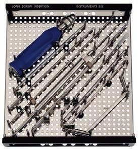
68 Sets VA Instruments VA Instruments and Long Screw Insertion Instruments 3.5, in Modular Tray, Vario Case System Vario Case for VA Instruments and Long Screw Insertion Instruments, size 1/1, including and Modular Tray for VA Instruments 3.5, size 1/2, without Contents, Vario Case System Modular Tray for Long Screw Insertion Instruments 3.5, size 1/2, without Contents, Vario Case System 66 DePuy Synthes VA-LCP Proximal Tibial Plate 3.5 Surgical Technique


69 Aiming Arm Instruments Aiming Arm Instruments for VA-LCP Proximal Tibial Plates 3.5, in Modular Tray, Vario Case System Modular Tray for Aiming Arm Instruments, for VA-LCP Proximal Tibial Plates 3.5, size 1/1, without Contents Screws Modular Screw Rack, with Drawer, Measuring Block and Lid, length 200 mm, height 115 mm, size 1 2, without Contents, Vario Case System Modular Tray, for Modular Screw Rack, for Screws Ø 3.5 mm, with Long Measuring Scale, size 1/3, without Contents, Vario Case System Surgical Technique VA-LCP Proximal Tibial Plate 3.5 DePuy Synthes 66
3.5 MM VA-LCP PROXIMAL TIBIA PLATE SYSTEM
 3.5 MM VA-LCP PROXIMAL TIBIA PLATE SYSTEM Part of the DePuy Synthes Variable Angle Periarticular Plating System SURGICAL TECHNIQUE TABLE OF CONTENTS INTRODUCTION 3.5 mm VA-LCP Proximal Tibial Plate 2 AO
LCP Low Bend Medial Distal Tibia Plates 3.5 mm. Anatomic plates with low profile head for intra- and extraarticular fractures.
 LCP Low Bend Medial Distal Tibia Plates 3.5 mm. Anatomic plates with low profile head for intra- and extraarticular fractures. Surgical Technique This publication is not intended for distribution in the
Periarticular Aiming Arm Instruments for LCP Proximal Tibial Plate 4.5/5.0. Part of the LCP Periarticular Aiming Arm Instrument System (large).
.") Technique Guide Periarticular Aiming Arm Instruments for LCP Proximal Tibial Plate 4.5/5.0. Part of the LCP Periarticular Aiming Arm Instrument System (large). Image intensifier control Warning This description
Technique Guide Periarticular Aiming Arm Instruments for LCP Proximal Tibial Plate 4.5/5.0. Part of the LCP Periarticular Aiming Arm Instrument System (large). Image intensifier control Warning This description
Technique Guide. 3.5 mm LCP Low Bend Medial Distal Tibia Plate Aiming Instruments. Part of the 3.5 mm LCP Percutaneous Instrument System.
 Technique Guide 3.5 mm LCP Low Bend Medial Distal Tibia Plate Aiming Instruments. Part of the 3.5 mm LCP Percutaneous Instrument System. Table of Contents Introduction 3.5 mm LCP Low Bend Medial Distal
3.5 mm LCP Low Bend Medial Distal Tibia Plate Aiming Instruments
 Part of the 3.5 mm LCP 3.5 mm LCP Low Bend Medial Distal Tibia Plate Aiming Instruments Surgical Technique TABLE OF CONTENTS INTRODUCTION 3.5 mm LCP Low Bend Medial Distal Tibia Plate 2 Aiming Instruments
LCP Proximal Tibial Plate 4.5/5.0 with Periarticular Aiming Arm Instruments
 LCP Proximal Tibial Plate 4.5/5.0 with Periarticular Aiming Arm Instruments Surgical Technique This publication is not intended for distribution in the USA. Instruments and implants approved by the AO
VA-LCP Condylar Plate 4.5/5.0. Part of the Synthes Variable Angle Periarticular Plating System.
 VA-LCP Condylar Plate 4.5/5.0. Part of the Synthes Variable Angle Periarticular Plating System. Technique Guide This publication is not intended for distribution in the USA. Instruments and implants approved
Technique Guide. LCP Distal Fibula Plates. Part of the Synthes locking compression plate (LCP) system.
 system.") Technique Guide LCP Distal Fibula Plates. Part of the Synthes locking compression plate (LCP) system. Table of Contents Introduction LCP Distal Fibula Plates 2 AO Principles 4 Indications 5 Surgical Technique
Technique Guide LCP Distal Fibula Plates. Part of the Synthes locking compression plate (LCP) system. Table of Contents Introduction LCP Distal Fibula Plates 2 AO Principles 4 Indications 5 Surgical Technique
2.4 mm Variable Angle LCP Volar Extra-Articular Distal Radius System. For fragment-specific fracture fixation with variable angle locking technology.
 2.4 mm Variable Angle LCP Volar Extra-Articular Distal Radius System. For fragment-specific fracture fixation with variable angle locking technology. Surgical Technique This publication is not intended
Part of the DePuy Synthes Locking Compression Plate (LCP ) System. 3.5 mm LCP Medial Proximal Tibia Plates
 System. 3.5 mm LCP Medial Proximal Tibia Plates") Part of the DePuy Synthes Locking Compression Plate (LCP ) System 3.5 mm LCP Medial Proximal Tibia Plates Surgical Technique Table of Contents Introduction 3.5 mm LCP Medial Proximal Tibia Plates 2 AO
Part of the DePuy Synthes Locking Compression Plate (LCP ) System 3.5 mm LCP Medial Proximal Tibia Plates Surgical Technique Table of Contents Introduction 3.5 mm LCP Medial Proximal Tibia Plates 2 AO
Low Bend Distal Tibia Plates
 Part of the DePuy Synthes Locking Compression Plate (LCP ) System 3.5 mm LCP Low Bend Medial Distal Tibia Plates Surgical Technique Table of Contents Introduction 3.5 mm LCP Low Bend Medial Distal Tibia
LCP DISTAL TIBIA PLATE
 LCP DISTAL TIBIA PLATE Instruments and implants approved by the AO Foundation. This publication is not intended for distribution in the USA. SURGICAL TECHNIQUE Image intensifier control This description
LCP Anterolateral Distal Tibia Plate 3.5. The low profile anatomic fixation system with optimal plate placement and angular stability.
 LCP Anterolateral Distal Tibia Plate 3.5. The low profile anatomic fixation system with optimal plate placement and angular stability. Technique Guide LCP Small Fragment System Table of Contents Introduction
2.7 mm/3.5 mm LCP Distal Fibula Plate
 Part of the DePuy Synthes Locking Compression Plate (LCP ) System 2.7 mm/3.5 mm LCP Distal Fibula Plate Surgical Technique Table of Contents Introduction 2.7 mm/3.5 mm LCP Distal Fibula Plates 2 AO Principles
3.5 mm LCP Extra-articular Distal Humerus Plate
 Part of the DePuy Synthes Locking Compression Plate (LCP ) System 3.5 mm LCP Extra-articular Distal Humerus Plate Surgical Technique Table of Contents Introduction 3.5 mm LCP Extra-articular Distal Humerus
LCP Medial Proximal Tibial Plate 3.5. Part of the Synthes small fragment Locking Compression Plate (LCP) system.
 system.") LCP Medial Proximal Tibial Plate 3.5. Part of the Synthes small fragment Locking Compression Plate (LCP) system. Technique Guide This publication is not intended for distribution in the USA. Instruments
LCP Medial Proximal Tibial Plate 3.5. Part of the Synthes small fragment Locking Compression Plate (LCP) system. Technique Guide This publication is not intended for distribution in the USA. Instruments
2.7 mm/3.5 mm Variable Angle LCP. Ankle Trauma System
 Part of the DePuy Synthes Variable Angle Locking Compression Plate (VA LCP ) System 2.7 mm/3.5 mm Variable Angle LCP Ankle Trauma System Surgical Technique Table of Contents Introduction 2.7 mm/3.5 mm
LCP Anterolateral Distal Tibia Plate 3.5. The low profile anatomic fixation system with optimal plate placement and angular stability.
 LCP Anterolateral Distal Tibia Plate 3.5. The low profile anatomic fixation system with optimal plate placement and angular stability. Technique Guide LCP Small Fragment System Table of Contents Introduction
VA-LCP Anterior Clavicle Plate. The anatomically precontoured fixation system with angular stability for clavicle shaft and lateral clavicle.
 Technique Guide VA-LCP Anterior Clavicle Plate. The anatomically precontoured fixation system with angular stability for clavicle shaft and lateral clavicle. Table of Contents Introduction VA-LCP Anterior
3.5 mm LCP Olecranon Plates
 Part of the DePuy Synthes Locking Compression Plate (LCP ) System 3.5 mm LCP Olecranon Plates Surgical Technique Table of Contents Introduction 3.5 mm LCP Olecranon Plates 2 AO Principles 3 Indications
LCP Medial Proximal Tibial Plate 4.5/5.0. Part of the Synthes LCP periarticular plating system.
 LCP Medial Proximal Tibial Plate 4.5/5.0. Part of the Synthes LCP periarticular plating system. Technique Guide This publication is not intended for distribution in the USA. Instruments and implants approved
LCP Condylar Plate 4.5/5.0. Part of the LCP Periarticular Plating System.
 LCP Condylar Plate 4.5/5.0. Part of the LCP Periarticular Plating System. Surgical Technique This publication is not intended for distribution in the USA. Instruments and implants approved by the AO Foundation.
4.5 mm LCP Medial Proximal Tibia Plates
 Part of the DePuy Synthes LCP Periarticular Plating System 4.5 mm LCP Medial Proximal Tibia Plates Surgical Technique Table of Contents Introduction 4.5 mm LCP Medial Proximal Tibia Plates 2 AO Principles
Periarticular Aiming Arm Instruments for LCP Condylar Plate 4.5/5.0. Part of the LCP Periarticular Aiming Arm Instrument System (large).
.") Periarticular Aiming Arm Instruments for LCP Condylar Plate 4.5/5.0. Part of the LCP Periarticular Aiming Arm Instrument System (large). Surgical Technique This publication is not intended for distribution
Periarticular Aiming Arm Instruments for LCP Condylar Plate 4.5/5.0. Part of the LCP Periarticular Aiming Arm Instrument System (large). Surgical Technique This publication is not intended for distribution
Long Volar Plates for Diaphyseal-Metaphyseal Radius Fractures LCP. Dia-Meta Volar Distal Radius Plates. Surgical Technique
 Long Volar Plates for Diaphyseal-Metaphyseal Radius Fractures LCP Dia-Meta Volar Distal Radius Plates Surgical Technique Table of Contents Introduction LCP Dia-Meta Volar Distal Radius Plates 2 AO Principles
LCP Distal Fibula Plates. Part of the Synthes locking compression plate (LCP) system.
 system.") LCP Distal Fibula Plates. Part of the Synthes locking compression plate (LCP) system. Surgical Technique This publication is not intended for distribution in the USA. Instruments and implants approved
LCP Distal Fibula Plates. Part of the Synthes locking compression plate (LCP) system. Surgical Technique This publication is not intended for distribution in the USA. Instruments and implants approved
Technique Guide. LCP Posterior Medial Proximal Tibial Plate 3.5. Part of the Synthes small fragment LCP system.
 Technique Guide LCP Posterior Medial Proximal Tibial Plate 3.5. Part of the Synthes small fragment LCP system. Table of Contents Introduction LCP Posterior Medial Proximal Tibial Plate 3.5 2 AO Principles
4.5 mm LCP Condylar Plate Aiming Instruments
 Part of the LCP Periarticular Aiming Instrument System (Large) 4.5 mm LCP Condylar Plate Aiming Instruments Surgical Technique Table of Contents Introduction 4.5 mm LCP Condylar Plate Aiming Instruments
Technique Guide. Locking Attachment Plate. For treatment of periprosthetic fractures.
 Technique Guide Locking Attachment Plate. For treatment of periprosthetic fractures. Table of Contents Introduction Locking Attachment Plate 2 Indications 4 Surgical Technique Patient Positioning 5 Preparation
Technique Guide. 3.5 mm LCP Low Bend Medial Distal Tibia Plates. Part of the Synthes locking compression plate (LCP) system.
 system.") Technique Guide 3.5 mm LCP Low Bend Medial Distal Tibia Plates. Part of the Synthes locking compression plate (LCP) system. Table of Contents Introduction 3.5 mm LCP Low Bend Medial Distal Tibia Plates
Technique Guide 3.5 mm LCP Low Bend Medial Distal Tibia Plates. Part of the Synthes locking compression plate (LCP) system. Table of Contents Introduction 3.5 mm LCP Low Bend Medial Distal Tibia Plates
Technique Guide. LCP Proximal Femoral Hook Plate 4.5/5.0. Part of the LCP Periarticular Plating System.
 Technique Guide LCP Proximal Femoral Hook Plate 4.5/5.0. Part of the LCP Periarticular Plating System. Table of Contents Introduction Features and Benefits 2 AO ASIF Principles 4 Indications 5 Surgical
Technique Guide. 2.7 mm/3.5 mm LCP Distal Fibula Plates. Part of the Synthes locking compression plate (LCP) system.
 system.") Technique Guide 2.7 mm/3.5 mm LCP Distal Fibula Plates. Part of the Synthes locking compression plate (LCP) system. Table of Contents Introduction 2.7 mm/3.5 mm LCP Distal Fibula Plates 2 AO Principles
Technique Guide 2.7 mm/3.5 mm LCP Distal Fibula Plates. Part of the Synthes locking compression plate (LCP) system. Table of Contents Introduction 2.7 mm/3.5 mm LCP Distal Fibula Plates 2 AO Principles
LCP Medial Distal Tibia Plate, without Tab. The Low Profile Anatomic Fixation System with Angular Stability and Optimal Screw Orientation.
 LCP Medial Distal Tibia Plate, without Tab. The Low Profile Anatomic Fixation System with Angular Stability and Optimal Screw Orientation. Technique Guide LCP Small Fragment System Table of Contents Introduction
3.5 mm LCP Anterolateral Distal Tibia Plates
 Part of the DePuy Synthes Locking Compression Plate (LCP ) System 3.5 mm LCP Anterolateral Distal Tibia Plates Surgical Technique Table of Contents Introduction 3.5 mm LCP Anterolateral Distal Tibia Plates
4.5 mm VA-LCP. Part of the Variable Angle Periarticular Plating System
 4.5 mm VA-LCP Curved Condylar Plate Part of the Variable Angle Periarticular Plating System Surgical Technique Table of Contents Introduction 4.5 mm VA-LCP Curved Condylar Plates 2 4.5 mm VA-LCP Curved
Variable Angle LCP Volar Rim Distal Radius Plate 2.4. For fragment-specific fracture fixation with variable angle locking technology.
 Technique Guide Variable Angle LCP Volar Rim Distal Radius Plate 2.4. For fragment-specific fracture fixation with variable angle locking technology. Image intensifier control Warning This description
LCP Periarticular Proximal Humerus Plate 3.5. The anatomic fixation system with anterolateral shaft placement.
 LCP Periarticular Proximal Humerus Plate 3.5. The anatomic fixation system with anterolateral shaft placement. Surgical Technique This publication is not intended for distribution in the USA. Instruments
LCP Medial Proximal Tibial Plate 3.5. Part of the Synthes small fragment Locking Compression Plate (LCP) system.
 system.") LCP Medial Proximal Tibial Plate 3.5. Part of the Synthes small fragment Locking Compression Plate (LCP) system. Surgical Technique This publication is not intended for distribution in the USA. Instruments
LCP Medial Proximal Tibial Plate 3.5. Part of the Synthes small fragment Locking Compression Plate (LCP) system. Surgical Technique This publication is not intended for distribution in the USA. Instruments
LCP Distal Fibula Plates. Part of the Synthes locking compression plate (LCP) system.
 system.") LCP Distal Fibula Plates. Part of the Synthes locking compression plate (LCP) system. Surgical Technique This publication is not intended for distribution in the USA. Instruments and implants approved
LCP Distal Fibula Plates. Part of the Synthes locking compression plate (LCP) system. Surgical Technique This publication is not intended for distribution in the USA. Instruments and implants approved
LCP Superior Clavicle Plate. The anatomically precontoured fixation system with angular stability for clavicle shaft and lateral clavicle.
 Technique Guide LCP Superior Clavicle Plate. The anatomically precontoured fixation system with angular stability for clavicle shaft and lateral clavicle. Table of Contents Introduction LCP Superior Clavicle
LCP Percutaneous Aiming System 3.5 for PHILOS. For less invasive surgery at the proximal humerus.
 LCP Percutaneous Aiming System 3.5 for PHILOS. For less invasive surgery at the proximal humerus. Surgical Technique This publication is not intended for distribution in the USA. Instruments and implants
Olecranon Osteotomy Nail. For simple fractures and osteotomies of the olecranon.
 Olecranon Osteotomy Nail. For simple fractures and osteotomies of the olecranon. Technique Guide Discontinued June 2016; AVAILABLE FOR IMPLANT REMOVAL PURPOSES ONLY DSEM/TRM/0517/0843 Table of Contents
Technique Guide. 3.5 mm LCP Proximal Tibia Plate. Part of the Synthes Small Fragment LCP System.
 Technique Guide 3.5 mm LCP Proximal Tibia Plate. Part of the Synthes Small Fragment LCP System. Table of Contents AO ASIF Principles of Internal Fixation 4 Indications/Contraindications 5 Surgical Technique
LCP Proximal Radius Plates 2.4. Plates for radial head rim and for radial head neck address individual fracture patterns of the proximal radius.
 LCP Proximal Radius Plates 2.4. Plates for radial head rim and for radial head neck address individual fracture patterns of the proximal radius. Surgical Technique This publication is not intended for
3.5 mm LCP Clavicle Hook Plates
 Part of the Synthes Locking Compression Plate (LCP ) System 3.5 mm LCP Clavicle Hook Plates Surgical Technique Table of Contents Introduction 3.5 mm LCP Clavicle Hook Plates 2 AO Principles 4 Indications
LCP Superior Clavicle Plate. The anatomically precontoured fixation system with angular stability for clavicle shaft and lateral clavicle.
 LCP Superior Clavicle Plate. The anatomically precontoured fixation system with angular stability for clavicle shaft and lateral clavicle. Surgical Technique This publication is not intended for distribution
3.5 mm LCP Distal Humerus Plates
 Part of the DePuy Synthes Locking Compression Plate (LCP ) System 3.5 mm LCP Distal Humerus Plates Surgical Technique Table of Contents Introduction 3.5 mm LCP Distal Humerus Plates 2 AO Principles 4 Indications
2.4 mm Variable Angle LCP Volar Extra-Articular Distal Radius System. For fragment-specific fracture fixation with variable angle locking technology.
 Technique Guide 2.4 mm Variable Angle LCP Volar Extra-Articular Distal Radius System. For fragment-specific fracture fixation with variable angle locking technology. Table of Contents Introduction 2.4
Technique Guide. 3.5 mm LCP Periarticular Proximal Humerus Plate. Part of the Synthes locking compression plate (LCP) system.
 system.") Technique Guide 3.5 mm LCP Periarticular Proximal Humerus Plate. Part of the Synthes locking compression plate (LCP) system. Table of Contents Introduction 3.5 mm LCP Proximal Humerus Plate 2 AO Principles
Technique Guide 3.5 mm LCP Periarticular Proximal Humerus Plate. Part of the Synthes locking compression plate (LCP) system. Table of Contents Introduction 3.5 mm LCP Proximal Humerus Plate 2 AO Principles
Technique Guide. PHILOS and PHILOS Long. The anatomic fixation system for the proximal humerus.
 Technique Guide PHILOS and PHILOS Long. The anatomic fixation system for the proximal humerus. Table of Contents Introduction PHILOS and PHILOS Long 2 AO Principles 4 Indications 5 Surgical Technique
LCP Distal Tibia Plate
 Surgical Technique LCP Locking Compression Plate Original Instruments and Implants of the Association for the Study of Internal Fixation AO/ASIF Table of contents Indications 3 Implants/Instruments 5 Surgical
3.5 mm LCP Hook Plate
 Part of the DePuy Synthes Locking Compression Plate (LCP ) System 3.5 mm LCP Hook Plate Surgical Technique Table of Contents Introduction 3.5 mm LCP Hook Plate 2 AO Principles 4 Indications 5 Clinical
3.5 mm Locking Attachment Plate
 For Treatment of Periprosthetic Fractures 3.5 mm Locking Attachment Plate Surgical Technique Table of Contents Introduction 3.5 mm Locking Attachment Plate 2 Indications 4 Surgical Technique Preparation
VA-LCP Ankle Trauma System 2.7/3.5. Our most comprehensive ankle plating system.
 VA-LCP Ankle Trauma System 2.7/3.5. Our most comprehensive ankle plating system. Surgical Technique This publication is not intended for distribution in the USA. Instruments and implants approved by the
OBSOLETED. LCP Medial Distal Tibia Plate, without Tab. The Low Profile Anatomic Fixation System with Angular Stability and Optimal Screw Orientation.
 LCP Medial Distal Tibia Plate, without Tab. The Low Profile Anatomic Fixation System with Angular Stability and Optimal Screw Orientation. Surgical Technique LCP Small Fragment System This publication
Technique Guide. 3.5 mm LCP Olecranon Plates. Part of the Synthes locking compression plate (LCP) system.
 system.") Technique Guide 3.5 mm LCP Olecranon Plates. Part of the Synthes locking compression plate (LCP) system. Table of Contents Introduction 3.5 mm LCP Olecranon Plates 2 AO Principles 3 Indications 3 Clinical
Technique Guide 3.5 mm LCP Olecranon Plates. Part of the Synthes locking compression plate (LCP) system. Table of Contents Introduction 3.5 mm LCP Olecranon Plates 2 AO Principles 3 Indications 3 Clinical
LCP Proximal Radius Plates 2.4. Plates for radial head rim and for radial head neck address individual fracture patterns of the proximal radius.
 Technique Guide LCP Proximal Radius Plates 2.4. Plates for radial head rim and for radial head neck address individual fracture patterns of the proximal radius. Table of Contents Introduction LCP Proximal
VA LOCKING CALCANEAL PLATES 2.7
 VA LOCKING CALCANEAL PLATES 2.7 Instruments and Implants approved by the AO Foundation. This publication is not intended for distribution in the USA. SURGICAL TECHNIQUE Image intensifier control Warning
VA-LCP Ankle Trauma System 2.7/3.5. Our most comprehensive ankle plating system.
 VA-LCP Ankle Trauma System 2.7/3.5. Our most comprehensive ankle plating system. Surgical Technique This publication is not intended for distribution in the USA. Instruments and implants approved by the
VA-LCP Olecranon Plates 2.7/3.5. The fracture-specific low-profile fixation system with variable angle locking technology.
 VA-LCP Olecranon Plates 2.7/3.5. The fracture-specific low-profile fixation system with variable angle locking technology. Surgical Technique This publication is not intended for distribution in the USA.
LCP Condylar Plate 4.5/5.0. Part of the LCP Periarticular Plating System.
 LCP Condylar Plate 4.5/5.0. Part of the LCP Periarticular Plating System. Surgical Technique This publication is not intended for distribution in the USA. Instruments and implants approved by the AO Foundation.
3.5 mm LCP Distal Tibia T-Plates
 Part of the DePuy Synthes Locking Compression Plate (LCP ) System 3.5 mm LCP Distal Tibia T-Plates Surgical Technique Table of Contents Introduction 3.5 mm LCP Distal Tibia T-Plates 2 AO Principles 4 Indications
LCP Anterolateral Distal Tibia Plate 3.5. The low profile anatomic fixation system with optimal plate placement and angular stability.
 LCP Anterolateral Distal Tibia Plate 3.5. The low profile anatomic fixation system with optimal plate placement and angular stability. Surgical Technique LCP Small Fragment System This publication is not
LCP Superior Anterior Clavicle Plate. The anatomically precontoured fixation system with angular stability for clavicle shaft and lateral clavicle.
 LCP Superior Anterior Clavicle Plate. The anatomically precontoured fixation system with angular stability for clavicle shaft and lateral clavicle. Surgical Technique This publication is not intended for
PROXIMAL FEMORAL NAIL REMOVAL SET
 PROXIMAL FEMORAL NAIL REMOVAL SET for PFN, TFN and PFNA/PFNA-II Instruments and Implants approved by the AO Foundation. This publication is not intended for distribution in the USA. SURGICAL TECHNIQUE
VA-LCP Anterior Clavicle Plate. The anatomically precontoured fixation system with angular stability for clavicle shaft and lateral clavicle.
 VA-LCP Anterior Clavicle Plate. The anatomically precontoured fixation system with angular stability for clavicle shaft and lateral clavicle. Surgical Technique This publication is not intended for distribution
Zimmer MIS Periarticular 3.5mm Proximal Tibial Locking Plate
 Zimmer MIS Periarticular 3.5mm Proximal Tibial Locking Plate Surgical Technique The Science of the Landscape Zimmer MIS Periarticular 3.5mm Proximal Tibial Locking Plate Surgical Technique 1 Zimmer MIS
The Locking Calcaneal Plate Instrument and Implant Sets
 Part of the DePuy Synthes Locking Compression Plate (LCP ) System The Locking Calcaneal Plate Instrument and Implant Sets Surgical Technique Table of Contents Introduction Locking Calcaneal Plate 2 AO
Technique Guide. 4.5 mm LCP Proximal Tibia Plates. Part of the Synthes LCP Periarticular Plating System.
 Technique Guide 4.5 mm LCP Proximal Tibia Plates. Part of the Synthes LCP Periarticular Plating System. Table of Contents Introduction 4.5 mm LCP Proximal Tibia Plates 2 AO Principles 4 Indications 5 Surgical
Technique Guide. 2.4 mm Variable Angle LCP Distal Radius System. For fragment-specific fracture fixation with variable angle locking technology.
 Technique Guide 2.4 mm Variable Angle LCP Distal Radius System. For fragment-specific fracture fixation with variable angle locking technology. Table of Contents Introduction 2.4 mm Variable Angle LCP
VA-LCP Distal Humerus Plates 2.7/3.5. The low-profile fixation system with variable angle locking technology.
 VA-LCP Distal Humerus Plates 2.7/3.5. The low-profile fixation system with variable angle locking technology. Technique Guide This publication is not intended for distribution in the USA. Instruments and
Small Fragment Locking Compression Plate (LCP ) System
 System") Stainless Steel and Titanium Small Fragment Locking Compression Plate (LCP ) System Surgical Technique Table of Contents Introduction Small Fragment Locking Compression Plate (LCP) System 2 AO Principles
Stainless Steel and Titanium Small Fragment Locking Compression Plate (LCP ) System Surgical Technique Table of Contents Introduction Small Fragment Locking Compression Plate (LCP) System 2 AO Principles
Technique Guide. TomoFix Osteotomy System. A comprehensive plating system for stable fixation of osteotomies around the knee.
 Technique Guide TomoFix Osteotomy System. A comprehensive plating system for stable fixation of osteotomies around the knee. Table of Contents Introduction TomoFix Osteotomy System 2 AO Principles 4 Indications
3.5 mm LCP Superior Anterior Clavicle Plates
 Part of the DePuy Synthes Locking Compression Plate (LCP ) System 3.5 mm LCP Superior Anterior Clavicle Plates Surgical Technique Table of Contents Introduction 3.5 mm LCP Superior Anterior Clavicle Plates
VA LCP MEDIAL COLUMN FUSION PLATES 3.5
 VA LCP MEDIAL COLUMN FUSION PLATES 3.5 Instruments and Implants approved by the AO Foundation. This publication is not intended for distribution in the USA. SURGICAL TECHNIQUE Image intensifier control
VA-LCP Distal Humerus Plates 2.7/3.5. The low-profile fixation system with variable angle locking technology.
 VA-LCP Distal Humerus Plates 2.7/3.5. The low-profile fixation system with variable angle locking technology. Surgical Technique This publication is not intended for distribution in the USA. Instruments
Surgical Technique. This publication is not intended for distribution in the USA. Instruments and implants approved by the AO Foundation.
 LCP Extra-articular Distal Humerus Plate. The anatomically shaped and angular stable fixation system for extraarticular fractures of the distal humerus. Surgical Technique This publication is not intended
Technique Guide. VA-LCP Distal Humerus Plates 2.7/3.5. The low-profile fixation system with variable angle locking technology.
 Technique Guide VA-LCP Distal Humerus Plates 2.7/3.5. The low-profile fixation system with variable angle locking technology. Image intensifier control Warning This description alone does not provide sufficient
2.4 mm LCP Radial Head Plates. Part of the Synthes LCP Distal Radius Plate System.
 2.4 mm LCP Radial Head Plates. Part of the Synthes LCP Distal Radius Plate System. Technique Guide Instruments and Implants approved by the AO Foundation Table of Contents Introduction 2.4 mm LCP Radial
LCP Proximal Femoral Hook Plate 4.5/5.0. Part of the LCP Periarticular Plating System.
 LCP Proximal Femoral Hook Plate 4.5/5.0. Part of the LCP Periarticular Plating System. Surgical Technique This publication is not intended for distribution in the USA. Instruments and implants approved
LCP Ulna Osteotomy System 2.7. Low profile angular stable fixation for ulna shortening osteotomies.
 LCP Ulna Osteotomy System 2.7. Low profile angular stable fixation for ulna shortening osteotomies. Surgical Technique This publication is not intended for distribution in the USA. Instruments and implants
LCP Locking Compression Plate. Surgical Technique
 LCP Locking Compression Plate Surgical Technique Image intensifier control This description alone does not provide sufficient background for direct use of DePuy Synthes products. Instruction by a surgeon
LCP Proximal Radius Plates 2.4. Plates for radial head rim and for radial head neck address individual fracture patterns of the proximal radius.
 LCP Proximal Radius Plates 2.4. Plates for radial head rim and for radial head neck address individual fracture patterns of the proximal radius. Surgical Technique This publication is not intended for
2.4 mm Variable Angle LCP Volar Rim Distal Radius Plates
 For Fragment-Specific Fracture Fixation With Variable Angle Locking Technology 2.4 mm Variable Angle LCP Volar Rim Distal Radius Plates Surgical Technique Table of Contents Introduction 2.4 mm Variable
Large Fragment LCP Instrument and Implant Set
 Part of the DePuy Synthes Locking Compression Plate (LCP ) System Large Fragment LCP Instrument and Implant Set Surgical Technique Table of Contents Introduction Large Fragment LCP Instrument and Implant
LISS PLT. The less invasive stabilization system for proximal tibia fractures.
 LISS PLT. The less invasive stabilization system for proximal tibia fractures. Technique Guide This publication is not intended for distribution in the USA. Instruments and implants approved by the AO
Cannulated Pediatric Osteotomy System (CAPOS)
") A Single System of Osteotomy Blade Plates and Cannulated Instrumentation Cannulated Pediatric Osteotomy System (CAPOS) Surgical Technique Table of Contents Introduction Cannulated Pediatric Osteotomy System
A Single System of Osteotomy Blade Plates and Cannulated Instrumentation Cannulated Pediatric Osteotomy System (CAPOS) Surgical Technique Table of Contents Introduction Cannulated Pediatric Osteotomy System
PHILOS and PHILOS Long. The anatomic fixation system for the proximal humerus.
 PHILOS and PHILOS Long. The anatomic fixation system for the proximal humerus. Surgical Technique This publication is not intended for distribution in the USA. Instruments and implants approved by the
LCP Distal Humerus Plates
 The anatomic fixation system for the distal humerus with angular stability Surgical technique LCP Locking Compression Plate Contents Indications and contraindications 2 Implants 3 Instruments 5 Preparation
ANGLED BLADE PLATES FOR ADULTS
 ANGLED BLADE PLATES FOR ADULTS Instruments and implants approved by the AO Foundation. This publication is not intended for distribution in the USA. SURGICAL TECHNIQUE Image intensifier control This description
Technique Guide. VA-Locking Intercarpal Fusion System. Variable angle locking technology for mediocarpal partial arthrodesis.
 Technique Guide VA-Locking Intercarpal Fusion System. Variable angle locking technology for mediocarpal partial arthrodesis. Table of Contents Introduction VA-Locking Intercarpal Fusion System 2 Indications
3.5 mm Clavicle Hook Plates
 A Single Solution for Lateral Clavicle Fractures and Acromioclavicular Joint Dislocations 3.5 mm Clavicle Hook Plates Surgical Technique Discontinued December 2017 DSUS/TRM/1016/1126(1) Table of Contents
Femoral Neck System. Surgical Technique
 Femoral Neck System Surgical Technique Image intensifier control This description alone does not provide sufficient background for direct use of DePuy Synthes products. Instruction by a surgeon experienced
Mandible External Fixator II. Provides treatment for fractures of the maxillofacial area.
 Mandible External Fixator II. Provides treatment for fractures of the maxillofacial area. Technique Guide This publication is not intended for distribution in the USA. Instruments and implants approved
LCP Metaphyseal Plates. For extra-articular fractures.
 LCP Metaphyseal Plates. For extra-articular fractures. Surgical Technique This publication is not intended for distribution in the USA. Instruments and implants approved by the AO Foundation. Image intensifier
LCP Wrist Fusion Set. Anatomic plates for total wrist fusion.
 LCP Wrist Fusion Set. Anatomic plates for total wrist fusion. Surgical Technique This publication is not intended for distribution in the USA. Instruments and implants approved by the AO Foundation. Image
LCP Pediatric Hip Plate 2.7. For proximal femoral osteotomies.
 LCP Pediatric Hip Plate 2.7. For proximal femoral osteotomies. Technique Guide This publication is not intended for distribution in the USA. Instruments and implants approved by the AO Foundation. Image
TOMOFIX Medial Distal Femur Plate
 For Closed-Wedge Varus Femoral Osteotomies TOMOFIX Medial Distal Femur Plate Surgical Techniquee TABLE OF CONTENTS INTRODUCTION TOMOFIX Medial Distal Femur Plate 2 AO Principles 4 Indications 5 SURGICAL