Distal Radius and Distal Ulna Plates System Self-Tapping Spherical Locking Screw Self-Tapping Conical Locking Screw Cortex Screw
|
|
|
- Penelope Benson
- 5 years ago
- Views:
Transcription


1 DISTAL RADIUS AND ULNA LOCKING PLATE SYSTEM Surgical Technique Distal Radius and Distal Ulna Plates System Self-Tapping Spherical Locking Screw Self-Tapping Conical Locking Screw Cortex Screw Approved by Distal Radius and Ulna Locking Plate Set Code
2


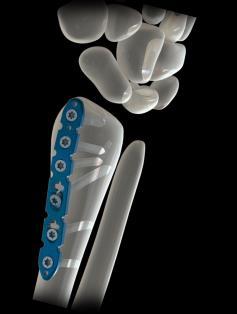
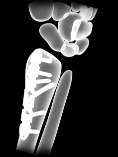
3 Distal Radius Volar Locking Plate Distal Radius Volar Locking Plate can be used for simple intra- or extra-articular fractures such as AO types A2, A3, B1- B3, and C1. The 4-hole head plate facilitates contouring of the plate to match the anatomy of the distal radius. Limited Contact Profile. Design reduces plate-to-bone contact, limiting vascular trauma. Narrow Plate design Variable Angle Distal Radius Locking Plate Screws can be angled around the central axis of the plate hole to provide additional fixation of the radial and intermediate columns Designed for simple and complex fractures (AO Types A2, A3, B1- B3, and C1-C3) Indicated for fixation of complex intra and extra-articular fractures and Osteotomies of the distal radius Two screw diameter sizes: 2.4 and 2.7mm Three different screw models per diameter: Spherical for and Conical Locking Screws and Cortex Screw 2, 3 and 4 orifices plates for right and left side 3

4 Variable Angle Distal Radius Straight Locking Plate Multi axial Distal Radius Radial Column Locing Plate Anatomically design for the distal third of the radius Variable angle distal radius straight locking plate can be used for simple intra or extraarticular fractures of the distal radius and corrective osteotomies of the distal radius Screw trajectories are angled to address a wide variety of fracture types. Limited contact profile. Design reduces plate-to-bone contact, limiting vascular trauma. Narrow Plate design. Variable Angle Distal Radius L Locking Plate Multi-axial Distal Radius Intermediate Column Locking Plate The 2-hole head is Anatomically design for the intermediate column of the distal radius Variable Angle Distal Radius L Locking Plates can be used for intraarticular dorsal fractures of the distal radius Sscrew trajectories are angled to address a wide variety of fracture types. Limited Contact Profile. Design reduces plate-to-bone contact, limiting vascular trauma. Narrow Plate design 4


5 Distal Radius Pi Locking Plate Distal Radius Pi Locking Plate are designed for the fixation of complex fractures and osteotomies of the dorsal distal radius precountoured for anatomical fit Limited Contact Profile. Design reduces plate-to-bone contact, limiting vascular trauma. Two proximal legs allow independent planes of fixation Cut -to-length design Distal Ulna Locking Plate Distal Ulna Locking Plates are designed for the fixation of fractures, osteotomies, nonunions, replantations, and fusions of the distal ulna Pointed hooks and locking screws in the head Anatomically precountoured. Narrow Plate design Limited Contact Profile. Design reduces plate-to-bone contact, limiting vascular trauma. 5
6
7 Contents Introduction General Surgical Technique Distal Radius Volar Locking Plate and Variable Angle Distal Radius Locking Plate Variable Angle Distal Radius Straight Locking Plate & Variable Angle Distal Radius L Locking Plate Distal Radius Pi Locking Plate Distal Unla Locking Plate Product Information Implants 35 Instruments 40 IMPORTANT: This device has not been evaluated for safety and compatibility in the MR environment This device has not been tasted for heating or migration in the MR environment 7


8 Introduction INDICATIONS: For fixation of complex intra- and extra-articular fractures and osteotomies of the distal radius and other small bones. 8

9 General Technique Temporary fixation with K-wires Instruments mm Kirschner Wire, stainless steel 1.6 mm K-wires can be placed directly through the designated orifices using a power operated drill. 9
10 General Surgical Technique Screw Insertion 2.4 mm spherical locking screws must be used in the distal portion of the variable angle distal radius plates (2.7mm spherical screws may be used in the distal position only in extreme cases the surgeon considers it necessary). 2.4 mm and 2.7mm conical locking or 2.4 mm and 2.7mm cortex screws can be used in the shaft of the plates. Distal Radius Volar Locking Plate can use conical 2.4mm and 2.7mm locking screws in the distal portion of the plate, and 2.4mm and 2.7mm conical locking screws along the plate, but only 2.4 mm and 2.7mm cortex screws can be used in the combi holes. Variable Angle Dorsal Plates can use 2.4mm and 2.7mm spherical and conical locking screws along the plate, but the combi holes. Selt-Tapping Spherical Locking Screw Selt-Tapping Conical Locking Screw Only 2.4 mm and 2.7mm cortex screws can be used in the combi holes in the shaft of the plates. Pi plates can use 2.4mm conical locking screws and conical buttress pins in the distal legs and 2.7mm conical locking screws and conical buttress pin in the proximal legs. Cortex Screw Distal Ulna Locking plate can use 2.4 and 2.7mm conical locking screws along the plate, but only 2.4 mm and 2.7mm cortex screws can be used in the combi holes. 2.4mm and 2.7mm buttress pins can be use for in the locking orifices along the variable angle distal radius straight locking plate, variable angle distal radius l locking plate and distal radius pi locking plate Conical Buttress Pin If a combination of locking and cortex screws is planned, a cortex screw should be used first to pull the plate to the bone. If a locking screw is used first, care should be taken to ensure that the plate is held securely to the bone to keep the plate from rotating off the bone as the screw is locked into the plate. Spherical Buttress Pin Note: A power drilling machine or drill bit handle is not provided with the instruments. Surgeon may use preferred instrument. 10
11 Cortex Screw Ø 2.4mm Ø 2.7mm Self-Tapping Conical Locking Screw Ø 2.4mm Ø 2.7mm Self-Tapping Spherical Locking Screw Ø 2.4mm Ø 2.7mm Spherical Buttress Pin Ø 2.4mm Ø 2.7mm Conical Buttress Pin Ø 2.4mm Ø 2.7mm 11


12 Cortex Screw Ø 2.4mm Ø 2.7mm Self-Tapping Conical Locking Screw Ø 2.4mm Ø 2.7mm Self-Tapping Spherical Locking Screw Ø 2.4mm Ø 2.7mm Spherical Buttress Pin Ø 2.4mm Ø 2.7mm Conical Buttress Pin Ø 2.4mm Ø 2.7mm 12


13 Cortex Screw Ø 2.4mm Ø 2.7mm Self-Tapping Conical Locking Screw Ø 2.4mm Ø 2.7mm Self-Tapping Spherical Locking Screw Ø 2.4mm Ø 2.7mm Spherical Buttress Pin Ø 2.4mm Ø 2.7mm Conical Buttress Pin Ø 2.4mm Ø 2.7mm 13
 or neutral ( buttress ) insertion of cortex screws. Use the 1.7 mm drill bit with depth mark for 2.")
14 General Surgical Technique 1 Insert cortex screws Instruments mm Drill Bit, with depth mark 1.9 mm Drill Bit, with depth mark 2.4 StarDrive Screwdriver with variable angle torque Depth Gauge Use the 1.7/1.9 Double Drill Guide for an eccentric ( compression ) or neutral ( buttress ) insertion of cortex screws. Use the 1.7 mm drill bit with depth mark for 2.4mm screws and 1.9mm drill bit with depth mark for 2.7mm screws to drill to the desired depth. Use the depth gauge to measure for screw lengths. Use a StarDrive screwdriver for all2.4mm and 2.7 mm cortex 14


15 General Surgical Technique Insert locking screws and buttress pins Instruments mm Drill Bit, with depth mark 1.9 mm Drill Bit, with depth mark 2.4 StarDrive Screwdriver with variable angle torque Depth Gauge 2.0 Solid Screwdriver Depth Gauge 2.4mm Drill Guide 2.7mm Drill Guide Variable Angle Guide Block Right Side Variable Angle Guide Block Left Side 15


16 General Surgical Technique Screw the variable angle guide block (right or left) for variable angle locking dital radius plate into to the plate with the 2.0 solid screwdriver until it is fully seated for distal screws. Screw the threaded 2.4mm drill guide for 2.4mm screws and 2.7mm drill guide for 2.7mm screws into a locking hole until it is fully seated. For other plates, screw the threaded 2.4 mm drill guide for 2.4 mm screws and 2.7 mm drill guide for 2.7 mm screw into a locking hole until it is fully seated. Use the 1.7mm drill bit depth mark for 2.4mm screws and 1.9mm drill bit with depth mark for 2.7mm screws to drill to the desired depth. 16


17 General Surgical Technique Determine screw length Remove the drill guide. Use the depth gauge to measure the screw length. Insert screw Insert locking screws manually with a T8 StarDrive screwdriver. Carefully tighten the locking screw. Excessive force is not necessary to lock the screw to the plate. Remove guide block after inserting distal screws. Insert Buttress pin Use the same technique as used for locking screws. When using plates containing parallel screw holes it is recommended to alternate the buttress pins with locking or cortex screws to reduce the risk of fracture displacement. For plates with parallel screw angles, each fragment that contains a buttress pin should also contain a screw. In plates with nonparallel screw angles, the buttress pins can be placed in any locking hole, with or without the addition of screws. 17

18 Distal Radius Volar Locking Plate and Variable Angle Distal Radius Locking Plate Determine which plate will be used depending on the fracture pattern and patient anatomy. Position Patient Place the patient in the supine position with the hand and arm on a hand table, preferably radiolucent for fluoroscopic imaging, The elbow should be fully extended and in full supination. 18
. Dissect between the FCR and the radial artery, exposing the pronator quadratus.")

19 Distal Radius Volar Locking Plate and Variable Angle Distal Radius Locking Plate Approach Make a longitudinal incision slightly radial to the flexor carpi radialis tendon (FCR). Dissect between the FCR and the radial artery, exposing the pronator quadratus. Detach the pronator quadratus from the lateral border of the radius and elevate it toward the ulna so the radius is exposed and elevate it toward the ulna so the radius is exposed and the fracture is visualized Important: Leave the volar wrist capsule intact to avoid devascularization of the fracture fragments and destabilization of the volar wrist ligaments. 19


20 Reduce fracture and position plate Instruments mm Drill Bit, with depth mark 1.9 mm Drill Bit, with depth mark 2.4 StarDrive Screwdriver with variable angle torque Depth Gauge 1.7/1.9 Double Drill Guide Reduction Clamp Reduce the fracture using the preferred reduction technique. A reduction clamp is provided with the instruments. The reduction method will be fracture specific. Apply the plate to fit the volar Surface of the distal radius and insert 2.4mm or 2.7mm cortex screw into the long hole in the shaft, following the method describe in the General Technique section. Adjust the plate position as necessary, and tighten the screw. Insert Kirschner Wires using a power operated drill into the distal and proximal small holes to position and temporary fix the plate to proceed to insert the distal screws. Wires may be removed and inserted again to verify plate and screws location 20
21 Insert DistalScrews Instruments mm Drill Bit, with depth mark 1.9 mm Drill Bit, with depth mark 2.4 StarDrive Screwdriver with variable angle torque 2.0 Solid Screwdriver Depth Gauge 2.4mm Drill Guide 2.7mm Drill Guide Variable Angle Guide Block Right Side Variable Angle Guide Block left Side The order of screw insertion in the shaft and metaphysis may vary depending on fracture pattem and reduction technique. For Variable Angle Locking Distal Radius Plate, select the appropriate guide block and secure it to the plate using the attachment screw with the solid screwdriver. Then, insert the 2.4mm drill guide with measuring into one of the distal plate holes. Ensure that the guide is firmly seated in the hole. For Distal Radius Volar Locking Plate, insert the 2.4mm or 2.7 mm drill guide with measuring into one fof the distal plate holes. Ensure that the guide is firmly seated in the hole. Drill with the 1.7mm or 1.9 mm drill bit and measure screw length witch the depth gauge, then insert a 2.4mm spherical locking for Variable Angle Locking Distal Radius Plate or 2.4 mm or 2.7 mm conical locking screw for distal radius volar locking plate using TB StarDrive screwdriver. Repeat this procedure for the remaining distal holes that will be filled. Verify plate and distal screw location with a kirschner wire before multiple screws. inserting Use the small holes in the distal plate to insert the wires. Remove guide block and kirschner wires when distal screw complete. insertion is 21
22 Insert remaining proximal screws Instruments mm Drill Bit, with depth mark 1.9 mm Drill Bit, with depth mark 2.4 StarDrive Screwdriver with variable angle torque Depth Gauge 2.4mm Drill Guide 2.7mm Drill Guide Kirschner Wire Determine where the 2.4mm or 2.7mm conical locking or 2.4mm or 2.7mm cortex screws will be used in the shaft of the volar plate. Following the steps described in the General Technique section, insert these screws, beginning with the most proximal screw. 22


23 Confirm proper joint reconstruction Confirm proper joint reconstruction, screw placement, and screw length, using multiple C-arm views. To ensure that the most distal screws are not in the joint, use additional views such as 10 tilted AP, 20 inclined lateral, and 45 pronated oblique. Close incision Instruments StarDrive Screwdriver with variable angle torque Use the arppropriate method for surgical closure of the incision. 23
24 Variable Angle Distal Radius Straight Locking Plate & Variable Angle Distal Radius L Locking Plate 1Position Patient Place the patient in the supine position with the hand and arm on a hand table, preferably radiolucent for fluoroscopic imaging, The elbow should be fully extended with the hand pronated. 24
25 Variable Angle Distal Radius Straight Locking Plate & Variable Angle Distal Radius L Locking Plate 2 Approach Make a straight incision 5cm to 9cm in length, approximately 2cm proximally from the base of the second metacarpal over lister s tubercle to the border of the muscle belly of the first extensor compartment. Open the extensor retinaculum using a longitudinal incision over the third compartment. Dissect the ex- tensor pollicis longus ( EPL ) tendon and place it in a vassel loop for manipulation. Elevate the second and fourth dorsal compartments subperiosteally to preserve the integrity of these com- partments so there will be no direct contact between the tendons and implants. On the ulnar side, continue to dissect toward the radi- al border of the DRUJ, preserving the ligament and joint capsule. On the radial side, dissect toward the brachioradialis tendon, to place the dorsoradial plate correctly to support the radialstyloid. 25

.")
26 3 Insert cortex screws mm Drill Bit, with depth mark 1.9 mm Drill Bit, with depth mark 2.4 StarDrive Screwdriver with variable angle torque Depth Gauge 1.7/1.9 Double Drill Guide Reduction Clamp Begin fixation on the intermediate column with the L Locking plate, adapting it carefully to the surface of the bone. This plate supports the intermediate column and fixes the dorsoulnar fragment. Fix the plate preliminarily with a 2.4mm cortex screw in the shaft fragment close to the fracture (buttress position). 4 Position Straight Locking plate For the radial column, position the Straight Locking plate beneath the first compartment to support the radial styloid. Fix it to the bone with a 2.4mm cortex screw in the shaft, close to the fracture. It should form an angle of approximately to the straight locking plate. Confirm correct reduction and position of the plates with fluoroscopy. 5 Complete fixation Using two screws in the distal fragment and two screws in the proximal fragment will usually provide sufficient stability. 6 Confirm proper joint reconstruction Confirm proper joint reconstruction, screw placement, and screw length using multiple C-arm views. Complete Fixation 7 Create flap Create a flap with the extensor retinaculum by pulling it underneath the EPL and suturingit. The extensor retinaculum lies between the EPL and the straight locking plate to avoid direct contact, with the structures. 8 Close incision Use the appropriate method for surgical closure of the incision. 26

27 Distal Radius Pi Locking Plate Position Patient Place the patient in the supine position with the hand and arm on a hand table, preferably radiolucent for fluoroscopic imaging. Make a straight longitudinal incision over the dorsal radius, between the second and third extensor compartments, extending 7 to 12 cm. Open the extensor retinaculum using a longitudinal incision between the first and second extensor compartments as shown below. Dorsal Surgical Approach Take care to elevate and mobilize the third compartment (extensor pollicis longus tendon), proximally and distally, and toranslocate it radially for better access to the fracture site. Elevate the second and fourth dorsal compartments subperiosteally to preserve the integrity of these compartments. 27

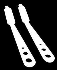
28 Distal Radius Pi Locking Plate 1 Shape template Temporarily position the bending template over the distal radius. Verify plate length and contour, then compare it to the distal radius plate. Note: The bending template can be used for either right-or left-hand plates. If a more proximal plate placement is desired, it may be necessary to remove 1-2 mm of the distal portion of lister s tubercle. 2 Cut Plate Place the pliers in the right hand. To cut the plate, open the pliers and slide the plate into the cutting slot from the left side as shown. The underside of the plate must be oriented toward the tip of the pliers. Cut the plate between the holes by aligning the plate in the center of the cutting slot. Do not cut through a plate hole. Squeeze the pliers closed to cut the plate. Note: Most cases will require removing holes from each arm and leg of the plate in order to fit patient anatomy and provide sufficient stability without increasing tissue dissection. 28


29 Distal Radius Pi Locking Plate 3 Contour distal plate arms If required, use the bending irons to contour the plate s articular arms to fit the distal radius. Thread a bending iron into a distal-arm plate hole. Thread another bending iron into the adjacent hole and gently spread the irons apart to create a convexbend. Note: Contour the plate small increments to avoid over bending and the need to re-bend. Excessive back-andforth bending may weaken or fracture the plate. 4 Contour proximal plate legs If needed, use the bending pliers to gently contour the proximal legs to better fit the distal shaft of the radius. 5 Apply plate Place the plate on the distal radius and determine which holes will be used for fixation. The fracture pattern and clinical situation will determine the specific order offixation ( proximal leg or distal arm ). 6 Secure distal arms Determine whether 2.4mm buttress pins or 2.4 conical locking screws will be used for fixation. A combination of both implants may be used. To secure the plate with 2.4mm buttress pins, screw a 2.4mm threaded drill guide into the threaded plate hole until seat- ed. Note: The threaded drill guide must be used to ensure the proper drilling angle. Otherwise, the buttress pins may not thread into the plate holes. Using the 1.7mm drill bit and guide, drill through both cortices. Buttress pins should be used bicortically. Exercise caution to avoid excessive protusion through the far cortex. 29

30 Dorsal Plate Technique Remove the drill guide and use the depth gauge ( ) to measure and select the appropriate length buttresspin. Note: Be sure to consider the width of any gap between the bone and plate when determining pin length. Tightening the screws will close this gap and result in pin tip protrusion beyond the far cortex, potentially causing soft tissue irritation. Using the 2.4mm stardrive screwdriver with variable angle torque ( ) push the buttress pin through the hole and turn until the threaded portion of the pin head locks into the plate. To secure the plate with 2.4mm conical locking screws, insert 2.4mm drill guide ( ) into the plate hole. Using the 1.7mm drill bit ( ) and 2.4mm threaded drill guide ( ), drill through both corices. Measure for screw length using the Depth gauge. Select and insert the appropriate 2.4mm conical locking screw using the stardrive screwdriver. Note: As with the buttress pins, be sure to consider the width of any gap between the bone and plate when determining screw length. Tightening the screws Will close this gap and result in screw tip protusion beyond the far cortex, potentially cau- sing soft tissue irritation. Note: Caution should be used in determining the placement angulation of the screws so that they do not interfere with each other or disrupt the articular surface. 7 Secure Proximal Kegs Place the 2.7 mm drill guide ( ) in the plate hole Drill through both cortices with a 1.9 mm drill bit ( ). Use the depth gauge ( ) to measure for screw length. Insert the appropiate lenght 2.7 mm cortical locking screw using the stardrive screwdriver. 8 Dorsal Leave compartments 2 and 3 (the extensor pollicis longus, extensor carpi radialis brevis and extensor carpi radialis longus tendons) above the extensor retinaculum at the time of wound closure, to protect soft tissue. 30

 Instrument Bending Pilers If necessary, contour the plate using the flat-nosed pliers. Notes: The plate holes have been designed to accept some degree of deformation.")
31 Distal Ulna Locking Plate 1 Approach The ideal insertion site for this implant is located toward the ulnar styloid and between the flexor carpi ulnaris and extensor carpi ulnaris tendons. Make a longitudinal skin incision over the palpable ulna, taking care to avoid the dorsal sensory branch of the ulnar nerve, which crosses the bone at this level. Once the distal shaft of the ulna is visible, subperiosteal dissection will allow the fracture fragments to be visualized and re-duce. Gently retract the dorsal sensory branch of the ulnar nerve. 2 Contour plate ( optional ) Instrument Bending Pilers If necessary, contour the plate using the flat-nosed pliers. Notes: The plate holes have been designed to accept some degree of deformation. The undercut helps to ensure that the threaded holes Will not be distorted with typical contouring. Significant distortion of the threaded holes will reduce ocking effectiveness. If posible, the plate should not be cut since the resulting sharp edges can irritate the overlying soft tissues. Precaution: The plate features pointed hooks which should be handled with care. 31
32 mm Kirschner Wire Expose and clean the fracture. Secure the pointed hooks of the distal ulna plate around the tip of the ulnar styloid, as a reference guide. In simple fractures of the ulnar neck, apply the plate to the subcutaneous border of the distal ulna, securing points of fixation in both the head and the shaft. Note: It may be necessary to temporarily stabilize the fracture with a transtyloid 1.6 mm kirschner wire. The wire should be inserted bettween the distal hooks of the temprarily applied plate. Precaution: The head of the distal ulna is often fragile. Caution should be exercised if using pointed reduction fórceps, since the forcé of this instrument may cause further comminution of the ulnar head. Much of the reduction Will be performed indirectly. Complete exposure of the ulnar head should not be performed because this will detach essential soft tissue stabilizers. 4 Fix plate distally mm Drill Bit with Depth Mark StarDrive Screwdriver Depth Gauge 2.4mm Drill Guide Secure the drill guide in the desired hole. Predrill the hole with the 1.7mm drill bit through the drill guide, and measure screw length directly from the gauge. Remove the drill bit and drill guide. Alternatively, screw length may be measured with the Depth gauge. Insert the appropriate length 2.4 mm conical locking screw. Complete Fixation 32

33 5 Adjust length and complete fixation Multiple options for screw insertion in the distal portion of the plate allow a wide range of fracture patterns to be securely stabilized. In franctures which require length adjustment, place one or two 2.4mm conical locking screws or 2.4mm conical buttress pin in the ulnar head to securely fix the implant distally. Place a 2.4 mm cortex screw in the oblong hole of the shaft, and obtain the correct length of reduction. Use a combination of cortex and locking screws in the surrounding holes to stabilize the fracture securely, as dictated by bone quality. In the case of unstable fractures of the base of the ulnar styloid a 2.4mm conical locking screw or 2.4mm conical buttress pin can be applied through the most distal hole in the plate. A locking screw does not need to reach the far cortex for stable fixation. Close and Implant Removal StarDriver Screwdriver In fractures where it is necessary to stabilize the tip of the ulnar styloid process, the distal plate hole is left empty. Remove the 1.6mm Kirschner wire, which was used for preliminary fixation. Overdrill the near fragment with a 1.7mm drill bit. Insert a 2.4mm cortex screw in lag mode between the arms of the distal hooks. Note: Use fluoroscopic imaging to verity that no screws enter either the distal radioulnar or ulnocarpal joints. 6 Close incision Use the appropiate method for surgical closure of the incision. Implant Removal for all plates To remove locking screws, unlock all screws from the plate and then remove screws completely from the bone. This prevents rotation of the plate when removing the last locking screw. 33
34


35 Implants Variable Angle Locking Distal Radius Plate Distal Radius Volar Locking Plate Code Holes Direction Width Right 46mm Right 58mm Right 67mm Left 46mm Left 58mm Left 67mm Code Holes Direction Width Right 44mm Left 44mm Right 55mm Left 55mm Right 66mm Left 66mm Variable Angle Locking Distal Radius Straight Locking Plate Distal Radius Pi Locking Plate Code Holes Width mm mm Code Holes Direction Width Right 64mm Left 64mm Right 74mm Left 74mm 35


36 Implants Distal Ulna Locking Plate Code Holes Width mm mm Variable Angle Distal Radius L Locking Plate Code Holes Direction Width Right 31mm Left 31mm Right 41mm Left 41mm 36
37 Implants Cortex Screw Ø 2.4 mm Ø 2.7 mm Code Length Code Length For use in round or combiholes Used to provide compression or neutral fixation With Stardrive recess 2.7mm for use in combiholes in the shaft of the plate Used to provide compression or neutral fixation ( 2.7mm ) mm mm mm mm mm mm mm mm mm mm mm mm mm mm mm mm mm mm mm mm mm mm Self-Tapping Conical Locking Screw Ø 2.4 mm Ø 2.7 mm Code Length Code Length Screws Used with the 2.4mm Distal Radius Plate Self-tapping with StatDrive recess Threaded, conical head locks securely into the threaded holes in the plate For proximal plate fixation mm mm mm mm mm mm mm mm mm mm mm mm mm mm mm mm mm mm mm mm mm mm 37
38 Implants Self-Tapping Spherical Locking Screw Ø 2.4 mm Ø 2.7 mm Code Length Code Length Threaded, spherical head locks securely into the threaded holes in the plate For distal plate fixation, if surgeon considers it necessary mm mm mm mm mm mm mm mm mm mm mm mm mm mm mm mm mm mm mm mm mm mm Spherical Buttress Pin Conical Buttress Pin Ø 2.4 mm Ø 2.7 mm Ø 2.4 mm Ø 2.7 mm Code Length Code Length Code Length Code Length mm mm mm mm mm mm mm mm mm mm mm mm mm mm mm mm mm mm mm mm mm mm mm mm mm mm mm mm mm mm mm mm mm mm mm mm mm mm mm mm mm mm mm mm 38
39


40 Instruments 40


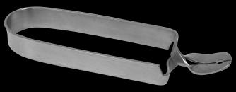
41 Instruments Verbrugge Clamp Code


42 Instruments 42
43

44 Contact 2002 Timberloch PI Suite 200 The Woodlands. TX, Approved by Distal Radius and Ulna Plate System Code
Distal Radius Plate Instrument and Implant Set. Discontinued December 2017 DSUS/TRM/0916/1063(1)
") Distal Radius Plate Instrument and Implant Set Surgical Technique Discontinued December 2017 DSUS/TRM/0916/1063(1) The Distal Radius Plates Indications For fixation of fractures and osteotomies, including
Distal Radius Plate Instrument and Implant Set Surgical Technique Discontinued December 2017 DSUS/TRM/0916/1063(1) The Distal Radius Plates Indications For fixation of fractures and osteotomies, including
Technique Guide. 2.4 mm Variable Angle LCP Distal Radius System. For fragment-specific fracture fixation with variable angle locking technology.
 Technique Guide 2.4 mm Variable Angle LCP Distal Radius System. For fragment-specific fracture fixation with variable angle locking technology. Table of Contents Introduction 2.4 mm Variable Angle LCP
2.4 mm Variable Angle LCP Volar Extra-Articular Distal Radius System. For fragment-specific fracture fixation with variable angle locking technology.
 Technique Guide 2.4 mm Variable Angle LCP Volar Extra-Articular Distal Radius System. For fragment-specific fracture fixation with variable angle locking technology. Table of Contents Introduction 2.4
Long Volar Plates for Diaphyseal-Metaphyseal Radius Fractures LCP. Dia-Meta Volar Distal Radius Plates. Surgical Technique
 Long Volar Plates for Diaphyseal-Metaphyseal Radius Fractures LCP Dia-Meta Volar Distal Radius Plates Surgical Technique Table of Contents Introduction LCP Dia-Meta Volar Distal Radius Plates 2 AO Principles
Distal Ulnar Locking Plate
 INDEX Indications Patient Position Surgical Technique - Step 1 Approach - Step 2 Plate Contouring - Step 3 Fracture Reduction - Step 4 Distal Plate Fixation - Step 5 Confirm Proper Reconstruction - Step
Variable Angle LCP Volar Rim Distal Radius Plate 2.4. For fragment-specific fracture fixation with variable angle locking technology.
 Technique Guide Variable Angle LCP Volar Rim Distal Radius Plate 2.4. For fragment-specific fracture fixation with variable angle locking technology. Image intensifier control Warning This description
Instrument and Implant for wrist fracture
 Instrument and Implant for wrist fracture Jansri Janpanya Product specialist The Bangkok Unitrade Co,.ltd. Objectives Type of LCP for distal radius Fx. The new LCP design for distal radius Fx. Have knowledge
2.4 mm LCP Distal Radius System
 A Comprehensive Plating System to Address a Variety of Fracture Patterns 2.4 mm LCP Distal Radius System Surgical Technique Table of Contents Introduction 2.4 mm LCP Distal Radius System 2 AO Principles
LCP Proximal Radius Plates 2.4. Plates for radial head rim and for radial head neck address individual fracture patterns of the proximal radius.
 Technique Guide LCP Proximal Radius Plates 2.4. Plates for radial head rim and for radial head neck address individual fracture patterns of the proximal radius. Table of Contents Introduction LCP Proximal
WINSTA-R. Distal Radius System
 Distal Radius System Table of Contents Introduction WINSTA-R System 2 Indication 2 Surgical Technique Palmar Access for Radius Plate 3 Dorsal Access for Radius Plate 3 Positioning of the Radius Plate
2.4 mm Variable Angle LCP Volar Extra-Articular Distal Radius System. For fragment-specific fracture fixation with variable angle locking technology.
 2.4 mm Variable Angle LCP Volar Extra-Articular Distal Radius System. For fragment-specific fracture fixation with variable angle locking technology. Surgical Technique This publication is not intended
LCP Medial Distal Tibia Plate, without Tab. The Low Profile Anatomic Fixation System with Angular Stability and Optimal Screw Orientation.
 LCP Medial Distal Tibia Plate, without Tab. The Low Profile Anatomic Fixation System with Angular Stability and Optimal Screw Orientation. Technique Guide LCP Small Fragment System Table of Contents Introduction
2.4 mm LCP Radial Head Plates. Part of the Synthes LCP Distal Radius Plate System.
 2.4 mm LCP Radial Head Plates. Part of the Synthes LCP Distal Radius Plate System. Technique Guide Instruments and Implants approved by the AO Foundation Table of Contents Introduction 2.4 mm LCP Radial
Distal Radius Plate 2.4/2.7 dorsal and volar
 Distal Radius Plate 2.4/2.7 dorsal and volar Surgical Technique This publication is not intended for distribution in the USA. Instruments and implants approved by the AO Foundation. Distal Radius Plate
Technique Guide. 3.5 mm LCP Low Bend Medial Distal Tibia Plates. Part of the Synthes locking compression plate (LCP) system.
 system.") Technique Guide 3.5 mm LCP Low Bend Medial Distal Tibia Plates. Part of the Synthes locking compression plate (LCP) system. Table of Contents Introduction 3.5 mm LCP Low Bend Medial Distal Tibia Plates
Technique Guide 3.5 mm LCP Low Bend Medial Distal Tibia Plates. Part of the Synthes locking compression plate (LCP) system. Table of Contents Introduction 3.5 mm LCP Low Bend Medial Distal Tibia Plates
Technique Guide. 3.5 mm LCP Olecranon Plates. Part of the Synthes locking compression plate (LCP) system.
 system.") Technique Guide 3.5 mm LCP Olecranon Plates. Part of the Synthes locking compression plate (LCP) system. Table of Contents Introduction 3.5 mm LCP Olecranon Plates 2 AO Principles 3 Indications 3 Clinical
Technique Guide 3.5 mm LCP Olecranon Plates. Part of the Synthes locking compression plate (LCP) system. Table of Contents Introduction 3.5 mm LCP Olecranon Plates 2 AO Principles 3 Indications 3 Clinical
Acu-Loc Wrist Spanning Plate System. Surgical Technique
 Acu-Loc Wrist Spanning Plate System Surgical Technique Acumed is a global leader of innovative orthopaedic and medical solutions. We are dedicated to developing products, service methods, and approaches
3.5 MM VA-LCP PROXIMAL TIBIA PLATE SYSTEM
 3.5 MM VA-LCP PROXIMAL TIBIA PLATE SYSTEM Part of the DePuy Synthes Variable Angle Periarticular Plating System SURGICAL TECHNIQUE TABLE OF CONTENTS INTRODUCTION 3.5 mm VA-LCP Proximal Tibial Plate 2 AO
3.5 mm LCP Olecranon Plates
 Part of the DePuy Synthes Locking Compression Plate (LCP ) System 3.5 mm LCP Olecranon Plates Surgical Technique Table of Contents Introduction 3.5 mm LCP Olecranon Plates 2 AO Principles 3 Indications
2.4 mm Variable Angle LCP Volar Rim Distal Radius Plates
 For Fragment-Specific Fracture Fixation With Variable Angle Locking Technology 2.4 mm Variable Angle LCP Volar Rim Distal Radius Plates Surgical Technique Table of Contents Introduction 2.4 mm Variable
Technique Guide. 3.5 mm LCP Low Bend Medial Distal Tibia Plate Aiming Instruments. Part of the 3.5 mm LCP Percutaneous Instrument System.
 Technique Guide 3.5 mm LCP Low Bend Medial Distal Tibia Plate Aiming Instruments. Part of the 3.5 mm LCP Percutaneous Instrument System. Table of Contents Introduction 3.5 mm LCP Low Bend Medial Distal
2.7 mm/3.5 mm Variable Angle LCP Elbow System DJ9257-B 1
 2.7 mm/3.5 mm Variable Angle LCP Elbow System DJ9257-B 1 System overview Simply complete: A comprehensive system, consisting of five (5) distal humerus plates and three (3) types of olecranon plates Implant
Acu-Loc Wrist Plating System. Surgical Technique
 Acu-Loc Wrist Plating System Surgical Technique Acumed is a global leader of innovative orthopaedic and medical solutions. We are dedicated to developing products, service methods, and approaches that
LCP Distal Humerus Plates
 The anatomic fixation system for the distal humerus with angular stability Surgical technique LCP Locking Compression Plate Contents Indications and contraindications 2 Implants 3 Instruments 5 Preparation
Low Bend Distal Tibia Plates
 Part of the DePuy Synthes Locking Compression Plate (LCP ) System 3.5 mm LCP Low Bend Medial Distal Tibia Plates Surgical Technique Table of Contents Introduction 3.5 mm LCP Low Bend Medial Distal Tibia
Technique Guide. 2.7 mm/3.5 mm LCP Distal Fibula Plates. Part of the Synthes locking compression plate (LCP) system.
 system.") Technique Guide 2.7 mm/3.5 mm LCP Distal Fibula Plates. Part of the Synthes locking compression plate (LCP) system. Table of Contents Introduction 2.7 mm/3.5 mm LCP Distal Fibula Plates 2 AO Principles
Technique Guide 2.7 mm/3.5 mm LCP Distal Fibula Plates. Part of the Synthes locking compression plate (LCP) system. Table of Contents Introduction 2.7 mm/3.5 mm LCP Distal Fibula Plates 2 AO Principles
SMV Scientific Bone Plate and Screw System Surgical Technique
 SMV Scientific Bone Plate and Screw System Surgical Technique Description: The SMV Scientific Bone Plate and Screw System consists of non-locking plates and bone screw fasteners in a variety of lengths,
2.4 mm Variable Angle LCP Dorsal Distal Radius Plate
 For Fragment-Specific Fracture Fixation With Variable Angle (VA) Locking Technology 2.4 mm Variable Angle LCP Dorsal Distal Radius Plate Surgical Technique Table of Contents Introduction 2.4 mm VA LCP
LCP Proximal Radius Plates 2.4. Plates for radial head rim and for radial head neck address individual fracture patterns of the proximal radius.
 LCP Proximal Radius Plates 2.4. Plates for radial head rim and for radial head neck address individual fracture patterns of the proximal radius. Surgical Technique This publication is not intended for
3.5 mm LCP Extra-articular Distal Humerus Plate
 Part of the DePuy Synthes Locking Compression Plate (LCP ) System 3.5 mm LCP Extra-articular Distal Humerus Plate Surgical Technique Table of Contents Introduction 3.5 mm LCP Extra-articular Distal Humerus
OBSOLETED. LCP Medial Distal Tibia Plate, without Tab. The Low Profile Anatomic Fixation System with Angular Stability and Optimal Screw Orientation.
 LCP Medial Distal Tibia Plate, without Tab. The Low Profile Anatomic Fixation System with Angular Stability and Optimal Screw Orientation. Surgical Technique LCP Small Fragment System This publication
LCP Anterolateral Distal Tibia Plate 3.5. The low profile anatomic fixation system with optimal plate placement and angular stability.
 LCP Anterolateral Distal Tibia Plate 3.5. The low profile anatomic fixation system with optimal plate placement and angular stability. Technique Guide LCP Small Fragment System Table of Contents Introduction
LCP Low Bend Medial Distal Tibia Plates 3.5 mm. Anatomic plates with low profile head for intra- and extraarticular fractures.
 LCP Low Bend Medial Distal Tibia Plates 3.5 mm. Anatomic plates with low profile head for intra- and extraarticular fractures. Surgical Technique This publication is not intended for distribution in the
VariAx TM Distal Radius Locking Plate System
 Osteosynthesis VariAx TM Distal Radius Locking Plate System Operative Technique Anatomical & Universal Volar Plates Dorsal Plates Fragment Specific Plates Introduction -15 +15 The NEW VariAx Distal Radius
Technique Guide. 3.5 mm LCP Periarticular Proximal Humerus Plate. Part of the Synthes locking compression plate (LCP) system.
 system.") Technique Guide 3.5 mm LCP Periarticular Proximal Humerus Plate. Part of the Synthes locking compression plate (LCP) system. Table of Contents Introduction 3.5 mm LCP Proximal Humerus Plate 2 AO Principles
Technique Guide 3.5 mm LCP Periarticular Proximal Humerus Plate. Part of the Synthes locking compression plate (LCP) system. Table of Contents Introduction 3.5 mm LCP Proximal Humerus Plate 2 AO Principles
LCP Anterolateral Distal Tibia Plate 3.5. The low profile anatomic fixation system with optimal plate placement and angular stability.
 LCP Anterolateral Distal Tibia Plate 3.5. The low profile anatomic fixation system with optimal plate placement and angular stability. Technique Guide LCP Small Fragment System Table of Contents Introduction
3.5 mm LCP Hook Plate
 Part of the DePuy Synthes Locking Compression Plate (LCP ) System 3.5 mm LCP Hook Plate Surgical Technique Table of Contents Introduction 3.5 mm LCP Hook Plate 2 AO Principles 4 Indications 5 Clinical
The NBX Non-Bridging External Fixator A Non-Bridging External Fixator/Locking Plate capturing a series of.062mm K-wires and 3mm half-pins that are
 The NBX Non-Bridging External Fixator A Non-Bridging External Fixator/Locking Plate capturing a series of.062mm K-wires and 3mm half-pins that are inserted in a multiplanar and multi-directional fashion
3.5 mm LCP Distal Humerus Plates
 Part of the DePuy Synthes Locking Compression Plate (LCP ) System 3.5 mm LCP Distal Humerus Plates Surgical Technique Table of Contents Introduction 3.5 mm LCP Distal Humerus Plates 2 AO Principles 4 Indications
Technique Guide. LCP Distal Fibula Plates. Part of the Synthes locking compression plate (LCP) system.
 system.") Technique Guide LCP Distal Fibula Plates. Part of the Synthes locking compression plate (LCP) system. Table of Contents Introduction LCP Distal Fibula Plates 2 AO Principles 4 Indications 5 Surgical Technique
Technique Guide LCP Distal Fibula Plates. Part of the Synthes locking compression plate (LCP) system. Table of Contents Introduction LCP Distal Fibula Plates 2 AO Principles 4 Indications 5 Surgical Technique
2.4 mm LCP Volar Column Distal Radius Plates. Part of the 2.4 mm LCP Distal Radius System.
 2.4 mm LCP Volar Column Distal Radius Plates. Part of the 2.4 mm LCP Distal Radius System. 12 anatomically shaped volar plates Multiple screw options for fixedangle support to articular surface Combi holes
VA-LCP Anterior Clavicle Plate. The anatomically precontoured fixation system with angular stability for clavicle shaft and lateral clavicle.
 Technique Guide VA-LCP Anterior Clavicle Plate. The anatomically precontoured fixation system with angular stability for clavicle shaft and lateral clavicle. Table of Contents Introduction VA-LCP Anterior
LCP Distal Tibia Plate
 Surgical Technique LCP Locking Compression Plate Original Instruments and Implants of the Association for the Study of Internal Fixation AO/ASIF Table of contents Indications 3 Implants/Instruments 5 Surgical
Surgical Technique. Distal Humerus Locking Plate
 Surgical Technique Distal Humerus Locking Plate PERI-LOC Locked Plating System Distal Humerus Locking Plate Surgical Technique Table of Contents Introduction...2 Indications...3 Plate Features...3 Patient
2.7 mm/3.5 mm LCP Distal Fibula Plate
 Part of the DePuy Synthes Locking Compression Plate (LCP ) System 2.7 mm/3.5 mm LCP Distal Fibula Plate Surgical Technique Table of Contents Introduction 2.7 mm/3.5 mm LCP Distal Fibula Plates 2 AO Principles
Olecranon Locking Plate II
 INDEX Indications Patient Position Fracture Reduction and Fixation Surgical Technique Step 1 Surgical Approach Step 2 Implantation Step 3 Proximal Locking Screw Insertion Step 4 Distal Screw Insertion
Acu-Loc 2 Wrist Plating System
 Surgical Technique Acu-Loc 2 Wrist Plating System Acumed is a global leader of innovative orthopaedic and medical solutions. We are dedicated to developing products, service methods, and approaches that
Technique Guide. LCP Proximal Femoral Hook Plate 4.5/5.0. Part of the LCP Periarticular Plating System.
 Technique Guide LCP Proximal Femoral Hook Plate 4.5/5.0. Part of the LCP Periarticular Plating System. Table of Contents Introduction Features and Benefits 2 AO ASIF Principles 4 Indications 5 Surgical
3.5 mm LCP Clavicle Hook Plates
 Part of the Synthes Locking Compression Plate (LCP ) System 3.5 mm LCP Clavicle Hook Plates Surgical Technique Table of Contents Introduction 3.5 mm LCP Clavicle Hook Plates 2 AO Principles 4 Indications
Surgical Technique. Wrist Plating System
 Surgical Technique Wrist Plating System Acumed is a global leader of innovative orthopaedic and medical solutions. We are dedicated to developing products, service methods, and approaches that improve
LCP Superior Clavicle Plate. The anatomically precontoured fixation system with angular stability for clavicle shaft and lateral clavicle.
 Technique Guide LCP Superior Clavicle Plate. The anatomically precontoured fixation system with angular stability for clavicle shaft and lateral clavicle. Table of Contents Introduction LCP Superior Clavicle
2.7 mm/3.5 mm Variable Angle LCP. Ankle Trauma System
 Part of the DePuy Synthes Variable Angle Locking Compression Plate (VA LCP ) System 2.7 mm/3.5 mm Variable Angle LCP Ankle Trauma System Surgical Technique Table of Contents Introduction 2.7 mm/3.5 mm
3.5 mm LCP Low Bend Medial Distal Tibia Plate Aiming Instruments
 Part of the 3.5 mm LCP 3.5 mm LCP Low Bend Medial Distal Tibia Plate Aiming Instruments Surgical Technique TABLE OF CONTENTS INTRODUCTION 3.5 mm LCP Low Bend Medial Distal Tibia Plate 2 Aiming Instruments
The Locking Calcaneal Plate Instrument and Implant Sets
 Part of the DePuy Synthes Locking Compression Plate (LCP ) System The Locking Calcaneal Plate Instrument and Implant Sets Surgical Technique Table of Contents Introduction Locking Calcaneal Plate 2 AO
Zimmer MIS Periarticular 3.5mm Proximal Tibial Locking Plate
 Zimmer MIS Periarticular 3.5mm Proximal Tibial Locking Plate Surgical Technique The Science of the Landscape Zimmer MIS Periarticular 3.5mm Proximal Tibial Locking Plate Surgical Technique 1 Zimmer MIS
Surgical Technique. Olecranon Locking Plate
 Surgical Technique Olecranon Locking Plate PERI-LOC Locked Plating System Olecranon Locking Plate Surgical Techniquealog Infor Table of Contents Introduction...2 Indications...3 Plate Features...3 Patient
Technique Guide. VA-Locking Intercarpal Fusion System. Variable angle locking technology for mediocarpal partial arthrodesis.
 Technique Guide VA-Locking Intercarpal Fusion System. Variable angle locking technology for mediocarpal partial arthrodesis. Table of Contents Introduction VA-Locking Intercarpal Fusion System 2 Indications
Acu-Loc 2 Wrist Plating System. Surgical Technique
 Acu-Loc 2 Wrist Plating System Surgical Technique Acumed is a global leader of innovative orthopaedic and medical solutions. We are dedicated to developing products, service methods, and approaches that
Zimmer Small Fragment Universal Locking System. Surgical Technique
 Zimmer Small Fragment Universal Locking System Surgical Technique Zimmer Small Fragment Universal Locking System 1 Zimmer Small Fragment Universal Locking System Surgical Technique Table of Contents Introduction
3.5 mm Locking Attachment Plate
 For Treatment of Periprosthetic Fractures 3.5 mm Locking Attachment Plate Surgical Technique Table of Contents Introduction 3.5 mm Locking Attachment Plate 2 Indications 4 Surgical Technique Preparation
3. PATIENT POSITIONING & FRACTURE REDUCTION 3 8. DISTAL GUIDED LOCKING FOR PROXIMAL NAIL PROXIMAL LOCKING FOR LONG NAIL 13
 Contents IMPLANT FEATURES 2 1. INDICATIONS 3 2. PRE-OPERATIVE PLANNING 3 3. PATIENT POSITIONING & FRACTURE REDUCTION 3 4. INCISION 4 5. ENTRY POINT 4-6 6. PROXIMAL NAIL INSERTION 6-7 7. PROXIMAL LOCKING
LCP Proximal Radius Plates 2.4. Plates for radial head rim and for radial head neck address individual fracture patterns of the proximal radius.
 LCP Proximal Radius Plates 2.4. Plates for radial head rim and for radial head neck address individual fracture patterns of the proximal radius. Surgical Technique This publication is not intended for
Technique Guide. Small Fragment Locking Compression Plate (LCP) System. Stainless steel and titanium.
 System. Stainless steel and titanium.") Technique Guide Small Fragment Locking Compression Plate (LCP) System. Stainless steel and titanium. Table of Contents Introduction Small Fragment Locking Compression Plate (LCP) System 2 AO Principles
Technique Guide Small Fragment Locking Compression Plate (LCP) System. Stainless steel and titanium. Table of Contents Introduction Small Fragment Locking Compression Plate (LCP) System 2 AO Principles
Small External Fixator Nonspanning Wrist Frame. For the treatment of wrist fractures.
 Small External Fixator Nonspanning Wrist Frame. For the treatment of wrist fractures. Technique Guide Part of the Small External Fixation System Small External Fixator Nonspanning Wrist Frame When to use
3.5 mm LCP Superior and Superior Anterior Clavicle Plates. Part of the Synthes modular clavicle plate system.
 3.5 mm LCP Superior and Superior Anterior Clavicle Plates. Part of the Synthes modular clavicle plate system. Technique Guide Instruments and implants approved by the AO Foundation Table of Contents Introduction
VA-LCP Olecranon Plates 2.7/3.5. The fracture-specific low-profile fixation system with variable angle locking technology.
 VA-LCP Olecranon Plates 2.7/3.5. The fracture-specific low-profile fixation system with variable angle locking technology. Surgical Technique This publication is not intended for distribution in the USA.
Small Fragment Locking Compression Plate (LCP ) System
 System") Stainless Steel and Titanium Small Fragment Locking Compression Plate (LCP ) System Surgical Technique Table of Contents Introduction Small Fragment Locking Compression Plate (LCP) System 2 AO Principles
Stainless Steel and Titanium Small Fragment Locking Compression Plate (LCP ) System Surgical Technique Table of Contents Introduction Small Fragment Locking Compression Plate (LCP) System 2 AO Principles
MICRONAIL. Intramedullary Distal Radius System SURGICAL TECHNIQUE
 MICRONAIL II Intramedullary Distal Radius System SURGICAL TECHNIQUE Contents Introduction 3 4 Chapter 1 5 Chapter 2 6 Appendix A 18 Appendix B 19 Surgeon Design Team Introduction Product Information Surgical
Surgical Technique. Calcaneal Locking Plate
 Surgical Technique Calcaneal Locking Plate PERI-LOC Locked Plating System Calcaneal Locking Plate Surgical TechniqueCatalog Infor Table of Contents Introduction...2 Indications...3 Plate Features...3 Patient
Surgical Technique Guide
 Surgical Technique Guide Minimally Invasive, Intramedullary Device For Distal Radius Fragility Fractures The Sonoma WRx Wrist Fracture Repair Device is flexible, inserting easily through a small incision
3.5 mm LCP Superior Anterior Clavicle Plates
 Part of the DePuy Synthes Locking Compression Plate (LCP ) System 3.5 mm LCP Superior Anterior Clavicle Plates Surgical Technique Table of Contents Introduction 3.5 mm LCP Superior Anterior Clavicle Plates
Surgical Technique. Anterolateral and Medial Distal Tibia Locking Plates
 Surgical Technique Anterolateral and Medial Distal Tibia Locking Plates PERI-LOC Periarticular Locked Plating System Anterolateral and Medial Distal Tibia Locking Plates Surgical Technique Contents Product
LCP Superior Clavicle Plate. The anatomically precontoured fixation system with angular stability for clavicle shaft and lateral clavicle.
 LCP Superior Clavicle Plate. The anatomically precontoured fixation system with angular stability for clavicle shaft and lateral clavicle. Surgical Technique This publication is not intended for distribution
System. Humeral Nail. Surgical Technique
 System Humeral Nail Surgical Technique Contents IMPLANT FEATURES 2 1. INDICATIONS 3 2. PRE-OPERATIVE PLANNING 3 3. PATIENT POSITIONING & FRACTURE REDUCTION 3 4. INCISION 4 5. ENTRY POINT 4-6 6. PROXIMAL
Wrist Fixation System
 Wrist Fixation System Anatomy / Fracture Implant EXTRA & SIMPLE ARTICULAR Volar Radius Volar Fixed Angle Plate Volar Bearing Plate Radial Peg Plate Volar Hook Plate Volar Buttress Pin Volar Shear Plate
VariAx Distal Radius Locking Plate System
 Osteosynthesis VariAx Distal Radius Locking Plate System Operative Technique Anatomical & Universal Volar Plates Dorsal Plates Fragment Specific Plates Introduction The VariAx Distal Radius Plating System
Surgical Technique. Forearm Fracture Solutions
 Surgical Technique Forearm Fracture Solutions Acumed is a global leader of innovative orthopaedic and medical solutions. We are dedicated to developing products, service methods, and approaches that improve
Surgical Technique. Clavicle Locking Plate
 Surgical Technique Clavicle Locking Plate PERI-LOC Locked Plating System Clavicle Locking Plate Surgical Technique Table of Contents Introduction...2 Indications...3 Plate Features...3 Patient Positioning...4
AcUMEDr. FoREARM ROD SYSTEM
 AcUMEDr FoREARM ROD SYSTEM FoREARM ROD SYSTEM Since 1988 Acumed has been designing solutions to the demanding situations facing orthopedic surgeons, hospitals and their patients. Our strategy has been
The Wrist Fusion Set. Stainless Steel and Titanium TECHNIQUE GUIDE. Instruments and implants approved by the AO Foundation
 The Wrist Fusion Set Stainless Steel and Titanium TECHNIQUE GUIDE Instruments and implants approved by the AO Foundation Three Plate Options Stainless Steel or Titanium* Standard Bend Stainless Steel [242.510]
Technique Guide. 3.5 mm LCP Proximal Tibia Plate. Part of the Synthes Small Fragment LCP System.
 Technique Guide 3.5 mm LCP Proximal Tibia Plate. Part of the Synthes Small Fragment LCP System. Table of Contents AO ASIF Principles of Internal Fixation 4 Indications/Contraindications 5 Surgical Technique
modular ClaVICle PlaTe system
 modular ClaVICle PlaTe system 3.7 mm/3.3 mm VA LCP Anterior Clavicle Plates and 3.3 mm Superior Anterior Clavicle Plates surgical TeChnIque Table of Contents Introduction Modular Clavicle Plate System
DISTAL ELBOW SET. proximal ulna plate SURGICAL TECHNIQUE GUIDE
 SURGICAL TECHNIQUE GUIDE DISTAL ELBOW SET proximal ulna plate As described by: Jorge L. Orbay, M.D. Miami Hand & Upper Extremity Institute Miami, Florida DISTAL ELBOW SET proximal ulna plate Indications
2.7 mm/3.5 mm VA-LCP Anterior Clavicle Plates. Part of the Synthes modular clavicle plate system.
 2.7 mm/3.5 mm VA-LCP Anterior Clavicle Plates. Part of the Synthes modular clavicle plate system. Technique Guide Instruments and implants approved by the AO Foundation Table of Contents Introduction 2.7
Technique Guide. Locking Attachment Plate. For treatment of periprosthetic fractures.
 Technique Guide Locking Attachment Plate. For treatment of periprosthetic fractures. Table of Contents Introduction Locking Attachment Plate 2 Indications 4 Surgical Technique Patient Positioning 5 Preparation
LCP Medial Proximal Tibial Plate 3.5. Part of the Synthes small fragment Locking Compression Plate (LCP) system.
 system.") LCP Medial Proximal Tibial Plate 3.5. Part of the Synthes small fragment Locking Compression Plate (LCP) system. Technique Guide This publication is not intended for distribution in the USA. Instruments
LCP Medial Proximal Tibial Plate 3.5. Part of the Synthes small fragment Locking Compression Plate (LCP) system. Technique Guide This publication is not intended for distribution in the USA. Instruments
WINSTA-C. Clavicle Plating System
 Clavicle Plating System Clinical Advisor Michael Kurer FRCS FRCS (Orth) Consultant Orthopaedic and Shoulder Surgeon North Middlesex University Hospital NHS Trust Table of Contents Introduction Indication
Small External Fixator Wrist Spanning Frame. For the treatment of wrist fractures.
 Small External Fixator Wrist Spanning Frame. For the treatment of wrist fractures. Technique Guide Part of the Small External Fixation System Small External Fixator Wrist Spanning Frame When to use The
Mini External Fixator.
 Mini External Fixator. Assembly and Surgical Technique This publication is not intended for distribution in the USA. Instruments and implants approved by the AO Foundation. Image intensifier control Warning
Volar Distal Radius Plating System Surgical Technique
 Volar Distal Radius Plating System Surgical Technique Acu-Loc 2 Volar Distal Radius Plating System Acumed is a global leader of innovative orthopaedic and medical solutions. We are dedicated to developing
Locking Ankle Plating System. Surgical Technique
 Locking Ankle Plating System Surgical Technique Acumed is a global leader of innovative orthopaedic and medical solutions. We are dedicated to developing products, service methods, and approaches that
Surgical Technique. Lower Extremity Plates and Straight Plates
 Surgical Technique Lower Extremity Plates and Straight Plates 2 Table of contents Overview...4 Indications... 4 Contraindications... 4 Screw Options... 5 Straight Plate Options... 6 Proximal Tibia Plate
Surgical Technique. 3.5mm and 4.5mm Lateral Proximal Tibia Locking Plates
 Surgical Technique 3.5mm and 4.5mm Lateral Proximal Tibia Locking Plates PERI-LOC Periarticular Locked Plating System 3.5mm and 4.5mm Lateral Proximal Tibia Locking Plate Surgical Technique Contents Product
Chapter 4: Forearm 4.3 Forearm shaft fractures, transverse (12-D/4)
") AO Manual of ESIN in children s fractures Chapter 4: Forearm 4.3 Forearm shaft fractures, transverse (12-D/4) Title AO Manual of ESIN in children Subtitle Elastic stable intramedullary nailing (ESIN) Author
AO Manual of ESIN in children s fractures Chapter 4: Forearm 4.3 Forearm shaft fractures, transverse (12-D/4) Title AO Manual of ESIN in children Subtitle Elastic stable intramedullary nailing (ESIN) Author
The Calcaneal Plate. The Synthes non-locking solution for the Calcaneus.
 The Calcaneal Plate. The Synthes non-locking solution for the Calcaneus. Surgical Technique This publication is not intended for distribution in the USA. Instruments and implants approved by the AO Foundation.
2.4 mm Variable Angle LCP Intercarpal Fusion System. Variable angle locking technology for mediocarpal partial arthrodesis.
 2.4 mm Variable Angle LCP Intercarpal Fusion System. Variable angle locking technology for mediocarpal partial arthrodesis. Technique Guide Instruments and implants approved by the AO Foundation Table
Angle Stable Distal Radial Plate System WINSTA-R
 Angle Stable Distal Radial Plate System WINSTA-R Priv.-Doz.Dr.med. Martin Walz Dr. med. Felix Menzinger Prof.Dr.med. Jürgen Rudigier www.marquardt-medizintechnik.de General The problem posed by metaphyseal
LCP Wrist Fusion Set. Anatomic plates for total wrist fusion.
 LCP Wrist Fusion Set. Anatomic plates for total wrist fusion. Technique Guide This publication is not intended for distribution in the USA. Instruments and implants approved by the AO Foundation. Table