Cochlear Implants. Medical Procedures. for MED EL Implant Systems. AW33290_2.0 (English US)
|
|
|
- Ruby Casey
- 6 years ago
- Views:
Transcription

1 Cochlear Implants Medical Procedures for MED EL Implant Systems AW33290_2.0 (English US)
2 This manual provides important instructions and safety information for MED EL Implant System users who have to undergo a medical procedure (e.g. MRI). As an implant user, you might have questions about undergoing further medical procedures. Your medical team may also want more information about any special considerations for implant users. This guidance provides information that will help prevent damage to your implant and injury to yourself. Please share this information with your healthcare provider. Mi1200 SYNCHRONY Mi1200 SYNCHRONY PIN Interference with other equipment, robustness of the device in special medical or diagnostic environments... 1 Magnetic Resonance Imaging (MRI) Safety Information...2 Mi1000 MED EL CONCERT Mi1000 MED EL CONCERT PIN Interference with other equipment, robustness of the device in special medical or diagnostic environments...6 Magnetic Resonance Imaging (MRI) Safety Information...7 SONATA Interference with other equipment, robustness of the device in special medical or diagnostic environments Magnetic Resonance Imaging (MRI) Safety Information PULSAR Interference with other equipment, robustness of the device in special medical or diagnostic environments Magnetic Resonance Imaging (MRI) Safety Information C Interference with other equipment, robustness of the device in special medical or diagnostic environments Magnetic Resonance Imaging (MRI) Safety Information... 19
3 Mi1200 SYNCHRONY Mi1200 SYNCHRONY PIN Interference with other equipment, robustness of the device in special medical or diagnostic environments Instruments used in electrosurgery can produce high-frequency voltages which may induce currents in the electrodes of implantable devices. Such currents may damage the implant and/or the surrounding tissue. Monopolar electrosurgical instruments must not be used in the head and neck region. If bipolar electrosurgical instruments are used, the tips of the cautery must be kept at least 5 mm away from the reference electrodes on the stimulator housing and any contacts of the active electrode. Generally remove your external components (e.g. audio processor and accessories) from your head when undergoing medical treatment where an electrical current is passed through your body, or at least carefully observe the correct functioning of your entire MED-EL Implant System during the initial stages of the treatment. Any necessary ionizing radiation therapy should be carefully considered and the risk of damage to the MED EL implant has to be carefully weighed against the medical benefit of such therapy. Electroshock or electroconvulsive therapy in the head and neck region must not be used. Such therapy may damage the implant and/or the surrounding tissue. Neurostimulation or diathermy must not be carried out in the area of the implant since it could lead to current induction at the electrodes. This may damage the implant and/or the surrounding tissue. This applies also to iontophoresis and any current inducing medical and/or cosmetic treatment. Ultrasonic therapy and imaging must not be used in the area of the implant, as the implant may inadvertently concentrate the ultrasound field and cause harm. MED EL Cochlear Implants are robust against 240 Gy ionizing radiation dose under 6 MV photon beam (pulsed radiation from a linear accelerator) with a field size FS = 30 cm 30 cm, source to surface distance SSD = 100 cm, depth = 0.8 cm in a 30 cm 30 cm 15 cm perspex phantom. MED EL external components need to be taken off during irradiation. Therapeutic ionizing radiation in general may damage electronic components of your MED EL Cochlear Implant System and such damage may not be immediately detected. In order to minimize the risk of tissue necrosis due to local overdose, during radiotherapeutic treatments, the implant should not be placed in the direct radiotherapeutic beam. Other treatments: The effects of a number of treatments are unknown, e.g. electrical examinations in the dental area. Please contact your clinic. 1
4 Mi1200 SYNCHRONY Mi1200 SYNCHRONY PIN Magnetic Resonance Imaging (MRI) Safety Information The external components of the MED EL Cochlear Implant System (audio processor and accessories) are MR Unsafe and need to be removed prior to scanning. The implant components of the MED EL Cochlear Implant System are MR Conditional. Patients implanted with a MED EL Cochlear Implant may be safely scanned with a MRI system without surgical removal of the internal magnet when adhering to the conditions for safe scanning listed below. The implant has a specially designed magnet which allows safe MRI scanning with the magnet in place, and there is no need to remove the implant magnet. The implant magnet can be surgically removed if needed to avoid imaging artifacts. The physician/mri operator should always be informed that a patient is a MED EL Cochlear Implant user and that the conditions for safe scanning below must be followed. Non-clinical testing has demonstrated that the MED EL Cochlear Implant is MR Conditional. A patient with this implant can be safely scanned in a MR system meeting the following conditions: Static magnetic field of 1.5 T or 3.0 T Maximum spatial field gradient of 2,900 G/cm (29 T/m) For 1.5 T systems (see Table 1): Only sequences in Normal Operating Mode with a maximum head Specific Absorption Rate (SAR) of 3.2 W/kg. For 3.0 T systems (see Table 1): 1. For head scans and scans with a landmark location that is less than 35 cm from the top of the head the MR system must be able to provide a SAR limit prediction that allows fractional SAR display. 2
5 Mi1200 SYNCHRONY Mi1200 SYNCHRONY PIN 2. Sequences in Normal Operating Mode only with the following SAR restrictions: a. For head scans: Maximum average head SAR must not exceed 1.6 W/kg (50 % of maximum head SAR). b. For landmark locations less than 35 cm from the top of the head: Maximum whole-body SAR must not exceed 1.0 W/kg. c. For landmark locations at least 35 cm away from the top of the head: Maximum whole-body SAR must not exceed 2.0 W/kg. MRI field strengths Average head SAR Average whole-body SAR Landmark location <35 cm from the top of the head Landmark location 35 cm from the top of the head 1.5 T 3.2 W/kg 2.0 W/kg 2.0 W/kg 3.0 T 1.6 W/kg 1.0 W/kg 2.0 W/kg Table 1: Specific Absorption Rate (SAR levels) For 1.5 T scans under the conditions listed above, the implant is expected to produce a maximum temperature rise of less than 2 C during 15 minutes of continuous MR scanning. For 3.0 T scans under the conditions listed above, the implant is expected to produce a maximum temperature rise of less than 3 C during 15 minutes of continuous MR scanning. Before patients enter any MRI room, all external components of the implant system (audio processor and accessories) must be removed from the head. Head transmit coils or multichannel transmit coils must not be used with a 3.0 T MR system. The patient should be lying on his/her back with the head aligned parallel to the long axis of the scanner. The head should not be tilted more than 30 degrees from the axis of the scanner. The patient should be advised not to tilt his/her head to the side; otherwise torque is exerted onto the implant magnet which might cause pain. For scans requiring a head coil, the head coil will maintain a proper head orientation. For scans without a head coil, appropriate padding that will prevent the head from tilting more than 30 degrees must be used. Testing has demonstrated that migration or magnet displacement will not occur when scanned under these conditions. For field strengths of 1.5 T and 3.0 T, an optional supportive head bandage may be placed over the implant, for instance using an elastic bandage wrapped tightly around the head at least three times (refer to Figure 1). The bandage shall fit tightly, but should not cause pain. 3
6 Mi1200 SYNCHRONY Mi1200 SYNCHRONY PIN The implant must not be damaged mechanically, electrically or in any other way. In case of additional implants, e.g. a hearing implant in the other ear: MRI safety guidelines for this additional implant must be met. During the scan, patients might perceive auditory sensations such as clicking or beeping. Adequate counseling of the patient is advised prior to performing the MRI. The likelihood and intensity of auditory sensations can be reduced by selecting sequences with a lower Specific Absorption Rate (SAR) and slower gradient slew rates. The magnet can be removed to reduce image artifacts. If the magnet is not removed, image artifacts are to be expected (refer to Figure 2 and Figure 3). The artifacts extend approximately 10 cm (3.9 ) in radius around the device in a Spin Echo scan. The exchange of the magnets with the Non-Magnetic Spacer and vice versa has been tested for at least five repetitions. The above instructions should also be followed if areas of the body other than the head are to be examined (e.g. knee, etc.). When lower extremities are to be examined, it is recommended that the patient s legs are positioned in the scanner first. If the conditions for safe scanning listed above are not followed, injury to the patient and/or damage to the implant may result! 4


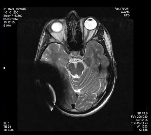
7 Mi1200 SYNCHRONY Mi1200 SYNCHRONY PIN Figure 1: Head bandage to support fixation of the implant Figure 2: Image artifacts of a spin echo sequence in axial view arising in a 1.5 T scanner. The left picture shows the artifacts obtained with the implant magnet in place, whereas the right picture illustrates the image artifacts when the implant magnet is replaced with the Non-Magnetic Spacer. Figure 3: Image artifacts of a spin echo sequence in axial view arising in a 3.0 T scanner. The left picture shows the artifacts obtained with the implant magnet in place, whereas the right picture illustrates the image artifacts when the implant magnet is replaced with the Non-Magnetic Spacer. 5
8 Mi1000 MED EL CONCERT Mi1000 MED EL CONCERT PIN Interference with other equipment, robustness of the device in special medical or diagnostic environments Instruments used in electrosurgery can produce high-frequency voltages which may induce currents in the electrodes of implantable devices. Such currents may damage the implant and/or the surrounding tissue. Monopolar electrosurgical instruments must not be used in the head and neck region. If bipolar electrosurgical instruments are used, the tips of the cautery must be kept at least 5 mm away from the reference electrodes on the stimulator housing and any contacts of the active electrode. Generally remove your external components (e.g. audio processor and accessories) from your head when undergoing medical treatment where an electrical current is passed through your body, or at least carefully observe the correct functioning of your entire MED-EL Implant System during the initial stages of the treatment. Any necessary ionizing radiation therapy should be carefully considered and the risk of damage to the MED EL implant has to be carefully weighed against the medical benefit of such therapy. Electroshock or electroconvulsive therapy in the head and neck region must not be used. Such therapy may damage the implant and/or the surrounding tissue. Neurostimulation or diathermy must not be carried out in the area of the implant since it could lead to current induction at the electrodes. This may damage the implant and/or the surrounding tissue. This applies also to iontophoresis and any current inducing medical and/or cosmetic treatment. Ultrasonic therapy and imaging must not be used in the area of the implant, as the implant may inadvertently concentrate the ultrasound field and cause harm. MED EL Cochlear Implants are robust against 240 Gy ionizing radiation dose under 6 MV photon beam (pulsed radiation from a linear accelerator) with a field size FS = 30 cm 30 cm, source to surface distance SSD = 100 cm, depth = 0.8 cm in a 30 cm 30 cm 15 cm perspex phantom. MED EL external components need to be taken off during irradiation. Therapeutic ionizing radiation in general may damage electronic components of your MED EL Cochlear Implant System and such damage may not be immediately detected. In order to minimize the risk of tissue necrosis due to local overdose, during radiotherapeutic treatments, the implant should not be placed in the direct radiotherapeutic beam. Other treatments: The effects of a number of treatments are unknown, e.g. electrical examinations in the dental area. Please contact your clinic. 6
9 Mi1000 MED EL CONCERT Mi1000 MED EL CONCERT PIN Magnetic Resonance Imaging (MRI) Safety Information The external components of the MED EL Cochlear Implant System (audio processor and accessories) are MR Unsafe and need to be removed prior to scanning. The implant components of the MED EL Cochlear Implant System are MR Conditional. Non-clinical testing has demonstrated that MED EL Cochlear Implants are MR Conditional. They can be safely scanned under the following conditions: 0.2 or 1.5 Tesla: Conditions: Bone thickness underneath the implant magnet of at least 0.4 mm. Bone thickness must be determined using CT images. Static magnetic field of 0.2 T or 1.5 T Spatial gradient field of up to 8 T/m (800 G/cm) Only sequences in Normal Operating Mode with a maximum whole-body averaged Specific Absorption Rate (SAR) of 2 W/kg and a maximum head averaged SAR of 3.2 W/kg Implantation performed at least 6 months ago Before patients enter any MRI room, all external components of the implant system (audio processor and accessories) must be removed. The implant is not damaged mechanically, electrically or in any other way. 7
10 Mi1000 MED EL CONCERT Mi1000 MED EL CONCERT PIN Additional MRI safety information for 0.2 or 1.5 Tesla scanning: Large image artifacts are to be expected. The size and shape of the image artifacts depend on the MRI sequence. The artifacts extend approximately 10 cm (3.9 in.) in radius around the device in a Spin Echo scan (refer to Figure 2). A supportive head bandage must be placed over the implant before entering the scanner room. This may be an elastic bandage wrapped tightly around the head at least three times (refer to Figure 1). The bandage needs to fit tightly, but should not cause pain. Head orientation: In case of 1.5 T systems, the longitudinal axis of the head must be parallel to the main magnetic field of the scanner. For example, this is the case when the patient is in a supine position with the head kept straight. The patient should not turn or bend his/her head to the side; otherwise partial demagnetization of the implant magnet is possible. During the scan, patients might perceive auditory sensations such as clicking or beeping. Adequate counseling of the patient is advised prior to performing the MRI. The likelihood and intensity of auditory sensations can be reduced by selecting sequences with a lower Specific Absorption Rate (SAR) and slower gradient slew rates. The above instructions should also be followed if areas of the body other than the head are to be examined (e.g. knee, etc.). When lower extremities are to be examined, it is recommended that the patient s legs are positioned in the scanner first to minimize any risk of weakening the implant magnet. In non-clinical testing and electromagnetic in-vivo computer simulations, the implant produced a maximum temperature rise <2 C during 15 minutes of continuous MR scanning in the Normal Operating Mode at a maximum whole-body averaged SAR of 2.0 W/kg and a maximum head averaged SAR of 3.2 W/kg. 8
11 Mi1000 MED EL CONCERT Mi1000 MED EL CONCERT PIN Figure 1: Head bandage to support fixation of the implant Figure 2: MR images obtained with a 1.5 T scanner (8-year-old child) 9
12 SONATA Interference with other equipment, robustness of the device in special medical or diagnostic environments Instruments used in electrosurgery can produce high-frequency voltages which may induce currents in the electrodes of implantable devices. Such currents may damage the implant and/or the surrounding tissue. Monopolar electrosurgical instruments must not be used in the head and neck region. If bipolar electrosurgical instruments are used, the tips of the cautery must be kept at least 5 mm away from the reference electrodes on the stimulator housing and any contacts of the active electrode. Generally remove your external components (e.g. audio processor and accessories) from your head when undergoing medical treatment where an electrical current is passed through your body, or at least carefully observe the correct functioning of your entire MED-EL Implant System during the initial stages of the treatment. Any necessary ionizing radiation therapy should be carefully considered and the risk of damage to the MED EL implant has to be carefully weighed against the medical benefit of such therapy. Electroshock or electroconvulsive therapy in the head and neck region must not be used. Such therapy may damage the implant and/or the surrounding tissue. Neurostimulation or diathermy must not be carried out in the area of the implant since it could lead to current induction at the electrodes. This may damage the implant and/or the surrounding tissue. This applies also to iontophoresis and any current inducing medical and/or cosmetic treatment. Ultrasonic therapy and imaging must not be used in the area of the implant, as the implant may inadvertently concentrate the ultrasound field and cause harm. MED EL Cochlear Implants are robust against 240 Gy ionizing radiation dose under 6 MV photon beam (pulsed radiation from a linear accelerator) with a field size FS = 30 cm 30 cm, source to surface distance SSD = 100 cm, depth = 0.8 cm in a 30 cm 30 cm 15 cm perspex phantom. MED EL external components need to be taken off during irradiation. Therapeutic ionizing radiation in general may damage electronic components of your MED EL Cochlear Implant System and such damage may not be immediately detected. In order to minimize the risk of tissue necrosis due to local overdose, during radiotherapeutic treatments, the implant should not be placed in the direct radiotherapeutic beam. Other treatments: The effects of a number of treatments are unknown, e.g. electrical examinations in the dental area. Please contact your clinic. 10
13 SONATA Magnetic Resonance Imaging (MRI) Safety Information The external components of the MED EL Cochlear Implant System (audio processor and accessories) are MR Unsafe and need to be removed prior to scanning. The implant components of the MED EL Cochlear Implant System are MR Conditional. Non-clinical testing has demonstrated that MED EL Cochlear Implants are MR Conditional. They can be safely scanned under the following conditions: 0.2 or 1.5 Tesla: Conditions: Bone thickness underneath the implant magnet of at least 0.4 mm. Bone thickness must be determined using CT images. Static magnetic field of 0.2 T or 1.5 T Spatial gradient field of up to 8 T/m (800 G/cm) Only sequences in Normal Operating Mode with a maximum whole-body averaged Specific Absorption Rate (SAR) of 2 W/kg and a maximum head averaged SAR of 3.2 W/kg Implantation performed at least 6 months ago Before patients enter any MRI room, all external components of the implant system (audio processor and accessories) must be removed. The implant is not damaged mechanically, electrically or in any other way. 11
14 SONATA Additional MRI safety information for 0.2 or 1.5 Tesla scanning: Large image artifacts are to be expected. The size and shape of the image artifacts depend on the MRI sequence. The artifacts extend approximately 10 cm (3.9 in.) in radius around the device in a Spin Echo scan (refer to Figure 2). A supportive head bandage must be placed over the implant before entering the scanner room. This may be an elastic bandage wrapped tightly around the head at least three times (refer to Figure 1). The bandage needs to fit tightly, but should not cause pain. Head orientation: In case of 1.5 T systems, the longitudinal axis of the head must be parallel to the main magnetic field of the scanner. For example, this is the case when the patient is in a supine position with the head kept straight. The patient should not turn or bend his/her head to the side; otherwise partial demagnetization of the implant magnet is possible. During the scan, patients might perceive auditory sensations such as clicking or beeping. Adequate counseling of the patient is advised prior to performing the MRI. The likelihood and intensity of auditory sensations can be reduced by selecting sequences with a lower Specific Absorption Rate (SAR) and slower gradient slew rates. The above instructions should also be followed if areas of the body other than the head are to be examined (e.g. knee, etc.). When lower extremities are to be examined, it is recommended that the patient s legs are positioned in the scanner first to minimize any risk of weakening the implant magnet. In non-clinical testing and electromagnetic in-vivo computer simulations, the implant produced a maximum temperature rise <2 C during 15 minutes of continuous MR scanning in the Normal Operating Mode at a maximum whole-body averaged SAR of 2.0 W/kg and a maximum head averaged SAR of 3.2 W/kg. 12
15 SONATA Figure 1: Head bandage to support fixation of the implant Figure 2: MR images obtained with a 1.5 T scanner (8-year-old child) 13
16 PULSAR Interference with other equipment, robustness of the device in special medical or diagnostic environments Instruments used in electrosurgery can produce high-frequency voltages which may induce currents in the electrodes of implantable devices. Such currents may damage the implant and/or the surrounding tissue. Monopolar electrosurgical instruments must not be used in the head and neck region. If bipolar electrosurgical instruments must be used, the tips of the cautery must be kept at least 3 cm away from the stimulator and all areas of the electrodes. Generally remove your external components (e.g. audio processor and accessories) from your head when undergoing medical treatment where an electrical current is passed through your body, or at least carefully observe the correct functioning of your entire MED-EL Implant System during the initial stages of the treatment. Any necessary ionizing radiation therapy should be carefully considered and the risk of damage to the MED EL implant has to be carefully weighed against the medical benefit of such therapy. Electroshock or electroconvulsive therapy in the head and neck region must not be used. Such therapy may damage the implant and/or the surrounding tissue. Neurostimulation or diathermy must not be carried out in the area of the implant since it could lead to current induction at the electrodes. This may damage the implant and/or the surrounding tissue. This applies also to iontophoresis and any current inducing medical and/or cosmetic treatment. A diagnostic level of ultrasonic energy of up to 500 W/m² within the range of 2 MHz to 5 MHz does not cause any damage to the implant. MED EL Cochlear Implants are robust against 240 Gy ionizing radiation dose under 6 MV photon beam (pulsed radiation from a linear accelerator) with a field size FS = 30 cm 30 cm, source to surface distance SSD = 100 cm, depth = 0.8 cm in a 30 cm 30 cm 15 cm perspex phantom. MED EL external components need to be taken off during irradiation. Therapeutic ionizing radiation in general may damage electronic components of your MED EL Cochlear Implant System and such damage may not be immediately detected. In order to minimize the risk of tissue necrosis due to local overdose, during radiotherapeutic treatments, the implant should not be placed in the direct radiotherapeutic beam. Other treatments: The effects of a number of treatments are unknown, e.g. electrical examinations in the dental area. Please contact your clinic. 14
17 PULSAR Magnetic Resonance Imaging (MRI) Safety Information The external components of the MED EL Cochlear Implant System (audio processor and accessories) are MR Unsafe and need to be removed prior to scanning. The implant components of the MED EL Cochlear Implant System are MR Conditional. Non-clinical testing has demonstrated that MED EL Cochlear Implants are MR Conditional. They can be safely scanned under the following conditions: 0.2 or 1.5 Tesla: Conditions: Bone thickness underneath the implant magnet of at least 0.4 mm. Bone thickness must be determined using CT images. Static magnetic field of 0.2 T or 1.5 T Spatial gradient field of up to 8 T/m (800 G/cm) Only sequences in Normal Operating Mode with a maximum whole-body averaged Specific Absorption Rate (SAR) of 2 W/kg and a maximum head averaged SAR of 3.2 W/kg Implantation performed at least 6 months ago Before patients enter any MRI room, all external components of the implant system (audio processor and accessories) must be removed. The implant is not damaged mechanically, electrically or in any other way. 15
18 PULSAR Additional MRI safety information for 0.2 or 1.5 Tesla scanning: Large image artifacts are to be expected. The size and shape of the image artifacts depend on the MRI sequence. The artifacts extend approximately 10 cm (3.9 in.) in radius around the device in a Spin Echo scan (refer to Figure 2). A supportive head bandage must be placed over the implant before entering the scanner room. This may be an elastic bandage wrapped tightly around the head at least three times (refer to Figure 1). The bandage needs to fit tightly, but should not cause pain. Head orientation: In case of 1.5 T systems, the longitudinal axis of the head must be parallel to the main magnetic field of the scanner. For example, this is the case when the patient is in a supine position with the head kept straight. The patient should not turn or bend his/her head to the side; otherwise partial demagnetization of the implant magnet is possible. During the scan, patients might perceive auditory sensations such as clicking or beeping. Adequate counseling of the patient is advised prior to performing the MRI. The likelihood and intensity of auditory sensations can be reduced by selecting sequences with a lower Specific Absorption Rate (SAR) and slower gradient slew rates. The above instructions should also be followed if areas of the body other than the head are to be examined (e.g. knee, etc.). When lower extremities are to be examined, it is recommended that the patient s legs are positioned in the scanner first to minimize any risk of weakening the implant magnet. In non-clinical testing and electromagnetic in-vivo computer simulations, the implant produced a maximum temperature rise <2 C during 15 minutes of continuous MR scanning in the Normal Operating Mode at a maximum whole-body averaged SAR of 2.0 W/kg and a maximum head averaged SAR of 3.2 W/kg. 16
19 PULSAR Figure 1: Head bandage to support fixation of the implant Figure 2: MR images obtained with a 1.5 T scanner (8-year-old child) 17
20 C40+ Interference with other equipment, robustness of the device in special medical or diagnostic environments Instruments used in electrosurgery can produce high-frequency voltages which may induce currents in the electrodes of implantable devices. Such currents may damage the implant and/or the surrounding tissue. Monopolar electrosurgical instruments must not be used in the head and neck region. If bipolar electrosurgical instruments must be used, the tips of the cautery must be kept at least 3 cm away from the stimulator and all areas of the electrodes. Generally remove your external components (e.g. audio processor and accessories) from your head when undergoing medical treatment where an electrical current is passed through your body, or at least carefully observe the correct functioning of your entire MED-EL Implant System during the initial stages of the treatment. Any necessary ionizing radiation therapy should be carefully considered and the risk of damage to the MED EL implant has to be carefully weighed against the medical benefit of such therapy. Electroshock or electroconvulsive therapy in the head and neck region must not be used. Such therapy may damage the implant and/or the surrounding tissue. Neurostimulation or diathermy must not be carried out in the area of the implant since it could lead to current induction at the electrodes. This may damage the implant and/or the surrounding tissue. This applies also to iontophoresis and any current inducing medical and/or cosmetic treatment. Ultrasonic therapy and imaging must not be used in the area of the implant, as the implant may inadvertently concentrate the ultrasound field and cause harm. MED EL Cochlear Implants are robust against 240 Gy ionizing radiation dose under 6 MV photon beam (pulsed radiation from a linear accelerator) with a field size FS = 30 cm 30 cm, source to surface distance SSD = 100 cm, depth = 0.8 cm in a 30 cm 30 cm 15 cm perspex phantom. MED EL external components need to be taken off during irradiation. Therapeutic ionizing radiation in general may damage electronic components of your MED EL Cochlear Implant System and such damage may not be immediately detected. In order to minimize the risk of tissue necrosis due to local overdose, during radiotherapeutic treatments, the implant should not be placed in the direct radiotherapeutic beam. Other treatments: The effects of a number of treatments are unknown, e.g. electrical examinations in the dental area. Please contact your clinic. 18
21 C40+ Magnetic Resonance Imaging (MRI) Safety Information The external components of the MED EL Cochlear Implant System (audio processor and accessories) are MR Unsafe and need to be removed prior to scanning. The implant components of the MED EL Cochlear Implant System are MR Conditional. Non-clinical testing has demonstrated that MED EL Cochlear Implants are MR Conditional. They can be safely scanned under the following conditions: 0.2 or 1.5 Tesla: Conditions: Bone thickness underneath the implant magnet of at least 0.4 mm. Bone thickness must be determined using CT images. Static magnetic field of 0.2 T or 1.5 T Spatial gradient field of up to 8 T/m (800 G/cm) Only sequences in Normal Operating Mode with a maximum whole-body averaged Specific Absorption Rate (SAR) of 2 W/kg and a maximum head averaged SAR of 3.2 W/kg Implantation performed at least 6 months ago Before patients enter any MRI room, all external components of the implant system (audio processor and accessories) must be removed. The implant is not damaged mechanically, electrically or in any other way. 19
22 C40+ Additional MRI safety information for 0.2 or 1.5 Tesla scanning: Large image artifacts are to be expected. The size and shape of the image artifacts depend on the MRI sequence. The artifacts extend approximately 10 cm (3.9 in.) in radius around the device in a Spin Echo scan (refer to Figure 2). A supportive head bandage must be placed over the implant before entering the scanner room. This may be an elastic bandage wrapped tightly around the head at least three times (refer to Figure 1). The bandage needs to fit tightly, but should not cause pain. Head orientation: In case of 1.5 T systems, the longitudinal axis of the head must be parallel to the main magnetic field of the scanner. For example, this is the case when the patient is in a supine position with the head kept straight. The patient should not turn or bend his/her head to the side; otherwise partial demagnetization of the implant magnet is possible. During the scan, patients might perceive auditory sensations such as clicking or beeping. Adequate counseling of the patient is advised prior to performing the MRI. The likelihood and intensity of auditory sensations can be reduced by selecting sequences with a lower Specific Absorption Rate (SAR) and slower gradient slew rates. The above instructions should also be followed if areas of the body other than the head are to be examined (e.g. knee, etc.). When lower extremities are to be examined, it is recommended that the patient s legs are positioned in the scanner first to minimize any risk of weakening the implant magnet. In non-clinical testing and electromagnetic in-vivo computer simulations, the implant produced a maximum temperature rise <2 C during 15 minutes of continuous MR scanning in the Normal Operating Mode at a maximum whole-body averaged SAR of 2.0 W/kg and a maximum head averaged SAR of 3.2 W/kg. 20

23 C40+ Figure 1: Head bandage to support fixation of the implant Figure 2: MR images obtained with a 1.5 T scanner (8-year-old child) 21

24 Symbols MR Conditional MR Unsafe Manufacturer Please visit us at Help and assistance are always available from your local office. Please refer to the accompanying Contact Sheet for your local office. 22
25 23
26 24
27
28 USA Distributor MED EL Corporation, USA 2511 Old Cornwallis Road, Suite 100 Durham, NC 27713, USA CAUTION: Federal (US) law restricts this device to sale, distribution and use by or on the order of a physician. MED EL Elektromedizinische Geräte GmbH Fürstenweg 77a 6020 Innsbruck, Austria office@medel.com medel.com
Cochlear Implants. Medical Procedures. for MED EL CI Systems. AW33290_5.0 (English US)
") Cochlear Implants Medical Procedures for MED EL CI Systems AW33290_5.0 (English US) This manual provides important instructions and safety information for MED EL CI System users who have to undergo a medical
Cochlear Implants Medical Procedures for MED EL CI Systems AW33290_5.0 (English US) This manual provides important instructions and safety information for MED EL CI System users who have to undergo a medical
MRI Checklist for MED EL CI and ABI models
 MRI Checklist for MED EL CI and ABI models Mi1200 SYNCHRONY Mi1200 SYNCHRONY PIN Mi1210 SYNCHRONY ST...1 Mi1200 SYNCHRONY ABI Mi1200 SYNCHRONY PIN ABI...2 Mi1000 CONCERTO Mi1000 CONCERTO PIN SONATA...3
MRI Safety Information for the HiRes Ultra 3D Cochlear Implant
 Advanced Bionics AG Laubisrütistrasse 28 8712 Stäfa, Switzerland +41 58 928 78 00 Manufactured by: Advanced Bionics LLC California, U.S.A. +1 661 362 1400 MRI Safety Information for the HiRes Ultra 3D
RONDO. User Manual. Cochlear Implants NOT FOR PRINT
 Cochlear Implants RONDO User Manual AW9389_3.0 (English US) Table of contents 1. Table of contents 1. TABLE OF CONTENTS 1 2. INTRODUCTION 3 3. INTENDED USE INDICATIONS CONTRA-INDICATIONS 4 Intended use
*smith&nephew. MRI Safety Information & Parameters for Smith & Nephew Orthopaedics AG. Knee Implants
 Knee Implants MRI Safety Information & Parameters for Smith & Nephew Orthopaedics AG Knee Implants *smith&nephew Supporting healthcare professionals for over 150 years Summary All knee implants of Smith
MRI Guidelines for the Axonics Sacral Neuromodulation System
 MRI Guidelines for the Axonics Sacral Neuromodulation System For Healthcare Professionals Rx only Note: This document is a supplement to the physician manuals provided with the Axonics SNM System. This
*smith&nephew. MRI Safety Information & Parameters for Smith & Nephew Orthopaedics AG. Shoulder Implants
 Shoulder Implants MRI Safety Information & Parameters for Smith & Nephew Orthopaedics AG Shoulder Implants *smith&nephew Supporting healthcare professionals for over 150 years Summary All shoulder implants
MRI GUIDELINES FOR INSPIRE THERAPY
 MRI GUIDELINES FOR INSPIRE THERAPY Clinician s Manual ONLY The following is a trademark of Inspire Medical Systems, Inc.: Inspire Introduction Read the information in this manual prior to conducting an
1.5 Tesla and 3 Tesla Magnetic Resonance Imaging (MRI) Guidelines for the Senza System (IPG1000 and IPG1500)
 Guidelines for the Senza System (IPG1000 and IPG1500)") 1.5 Tesla and 3 Tesla Magnetic Resonance Imaging (MRI) Guidelines for the Senza System (IPG1000 and IPG1500) ONLY NEVRO CORP. All questions or concerns about Nevro products should be forwarded to: Nevro
1.5 Tesla and 3 Tesla Magnetic Resonance Imaging (MRI) Guidelines for the Senza System (IPG1000 and IPG1500) ONLY NEVRO CORP. All questions or concerns about Nevro products should be forwarded to: Nevro
1.5 Tesla and 3 Tesla Magnetic Resonance Imaging (MRI) Guidelines for the Senza System (IPG1000 and IPG1500)
 Guidelines for the Senza System (IPG1000 and IPG1500)") 1.5 Tesla and 3 Tesla Magnetic Resonance Imaging (MRI) Guidelines for the Senza System (IPG1000 and IPG1500). ONLY NEVRO CORP. All questions or concerns about Nevro products should be forwarded to: Nevro
1.5 Tesla and 3 Tesla Magnetic Resonance Imaging (MRI) Guidelines for the Senza System (IPG1000 and IPG1500). ONLY NEVRO CORP. All questions or concerns about Nevro products should be forwarded to: Nevro
MRI GUIDELINES FOR INSPIRE THERAPY
 MRI GUIDELINES FOR INSPIRE THERAPY Clinician s Manual The following is a trademark of Inspire Medical Systems, Inc.: Inspire This product and/or the use of this product in a method may be covered by one
*smith&nephew. MRI Safety Information & Parameters for Smith & Nephew Orthopaedics AG. Hip Implants
 Hip Implants MRI Safety Information & Parameters for Smith & Nephew Orthopaedics AG Hip Implants *smith&nephew Supporting healthcare professionals for over 150 years Summary All hip implants of Smith &
Algovita. MRI Procedure Guidelines. Spinal Cord Stimulation System. 201x
 Algovita Spinal Cord Stimulation System MRI Procedure Guidelines Read this manual before performing an MRI scan on a patient implanted with an Algovita Spinal Cord Stimulation System. ONLY 201x Algovita
Read this manual before performing an MRI scan on a patient implanted with an Algovita Spinal Cord Stimulation System.
 Algovita Spinal Cord Stimulation System MRI Procedure Guidelines Read this manual before performing an MRI scan on a patient implanted with an Algovita Spinal Cord Stimulation System. ONLY 0300-000175-001
ImageReady MRI Full Body Guidelines for Precision Montage MRI Spinal Cord Stimulator System
 ImageReady MRI Full Body Guidelines for Precision Montage MRI Spinal Cord Stimulator System CAUTION: Federal law restricts this device to sale, distribution and use by or on the order of a physician. 91035972-02
Magnetic resonance imaging safety of NucleusR 24 cochlear implants at 3.0 T
 International Congress Series 1273 (2004) 394 398 www.ics-elsevier.com Magnetic resonance imaging safety of NucleusR 24 cochlear implants at 3.0 T F. Risi*, A. Saldanha, R. Leigh, P. Gibson Cochlear Limited,
VNS Therapy System Physician s Manual
 VNS Therapy System Physician s Manual Pulse Generator Model 102 Pulse Duo Generator Model 102R Demipulse Generator Model 103 Demipulse Duo Generator Model 104 AspireHC Generator Model 105 AspireSR Generator
Warning: Patients should not be exposed to MRI environments until the surgical site following pump implantation is fully healed.
 Prometra and Prometra II Programmable Pumps Magnetic Resonance Imaging (MRI) Safety Information GENERAL MR Conditional WARNING: FAILURE TO EMPTY THE PUMP PRIOR TO EXPOSURE TO MRI ENVIRONMENT COULD RESULT
1.5 Tesla and 3 Tesla Magnetic Resonance Imaging (MRI) Guidelines for the Senza System
 Guidelines for the Senza System") 1.5 Tesla and 3 Tesla Magnetic Resonance Imaging (MRI) Guidelines for the Senza System ONLY 11096 Rev B 1 NEVRO CORP. All questions or concerns about Nevro products should be forwarded to: Nevro Corp.
1.5 Tesla and 3 Tesla Magnetic Resonance Imaging (MRI) Guidelines for the Senza System ONLY 11096 Rev B 1 NEVRO CORP. All questions or concerns about Nevro products should be forwarded to: Nevro Corp.
2014 AAPM 56 th Annual Meeting
 2014 AAPM 56 th Annual Meeting SAM Diagnostic Radiology MR Safety - Deep Brain Stimulator and Other Neurostimulators Yunhong Shu, Ph.D. Mayo Clinic, Rochester, MN Outline Background of Neurostimulator
ImageReady MRI Head Only Guidelines for Spectra WaveWriter Spinal Cord Stimulator System
 ImageReady MRI Head Only Guidelines for Spectra WaveWriter Spinal Cord Stimulator System CAUTION: Federal law restricts this device to sale, distribution and use by or on the order of a physician. 91171762-01
MRI-Ready Systems Manual. MRI Procedure Information for the St. Jude Medical MR Conditional System
 MRI-Ready Systems Manual MRI Procedure Information for the St. Jude Medical MR Conditional System CAUTION: Federal (USA) law restricts this device to sale by or on the order of a physician. WARNING: This
WallFlex Biliary RX Partially Covered Stent System Prescriptive Information
 Caution/Rx Only: Federal Law (USA) restricts this device to sale by or on the order of a physician. Intended Use/Indications for Use The WallFlex Biliary RX is indicated for use in the palliative treatment
Yasargil Permanent Aneurysm Clips
 Yasargil Permanent Aneurysm Clips Yasargil aneurysm clips Figure captions 1 Yasargil Phynox aneurysm clip, example of a straight clip 2 Yasargil titanium aneurysm clip, example of a straight clip 3 Yasargil
Micra MC1VR01. MRI procedural information for Micra Model MC1VR01 MR Conditional single chamber transcatheter pacing device (VVIR)
") Micra MC1VR01 MRI procedural information for Micra Model MC1VR01 MR Conditional single chamber transcatheter pacing device (VVIR) MRI Technical Manual The following list includes trademarks or registered
Micra MC1VR01 MRI procedural information for Micra Model MC1VR01 MR Conditional single chamber transcatheter pacing device (VVIR) MRI Technical Manual The following list includes trademarks or registered
For Professionals. SYNCHRONY System. In Sync with Natural Hearing
 For Professionals SYNCHRONY System In Sync with Natural Hearing For more natural hearing in any listening environment SONNET Audio Processor RONDO Single-Unit Processor Designed for exceptional hearing
MRI Procedure Information. For St. Jude Medical MR Conditional Neurostimulation Systems. Clinician's Manual
 MRI Procedure Information For St. Jude Medical MR Conditional Neurostimulation Systems Clinician's Manual Unless otherwise noted, indicates that the name is a trademark of, or licensed to, St. Jude Medical
MRI guidelines for Medtronic neurostimulation systems for chronic pain
 MRI guidelines for Medtronic neurostimulation systems for chronic pain See "START HERE" section before conducting MRI. Instructions for use! USA Rx only Explanation of symbols on product or package labeling
8/28/18. Anesthetic considerations for patients with implanted devices for treating chronic pain and more. Objectives:
 Anesthetic considerations for patients with implanted devices for treating chronic pain and more Alaa Abd-Elsayed, MD, MPH Medical Director, UW Pain Services Medical Director, Pain Clinic Section Head,
User Manual: Ives MR Conditional Cup Electrodes J.R. Ives, December 22, 2017
 User Manual: Ives MR Conditional Cup Electrodes J.R. Ives, December 22, 2017 Ives EEG Solutions; 25 Storey Ave., #118, Newburyport, MA, 01950; ph: 978-358-8006; fax: 978-358-7825; www.iveseegsolutions.com
DISTAL RADIUS. Instructions for Use
 DISTAL RADIUS Instructions for Use CAUTION: FEDERAL LAW RESTRICTS THESE DEVICES TO SALE BY OR ON THE ORDER OF A PHYSICIAN. Table of Contents 1. INTENDED USE... 3 2. DEVICE DESCRIPTION... 3 3. METHOD OF
MRI Procedure Information. For St. Jude Medical MR Conditional Neurostimulation Systems. Clinician's Manual
 MRI Procedure Information For St. Jude Medical MR Conditional Neurostimulation Systems Clinician's Manual Unless otherwise noted, indicates that the name is a trademark of, or licensed to, St. Jude Medical
EasyStep. Operative technique
 Operative technique EasyStep - Step staple This publication sets forth detailed recommended procedures for using Stryker Osteosynthesis devices and instruments. It offers guidance that you should heed,
LCP Metaphyseal Plates. For extra-articular fractures.
 LCP Metaphyseal Plates. For extra-articular fractures. Surgical Technique This publication is not intended for distribution in the USA. Instruments and implants approved by the AO Foundation. Image intensifier
Safety Issue of Static Magnetic Field (1)
") MRI Safety Safety Issue of Static Magnetic Field (1) Currently, typical MRI utilizes static field with strengths of 0.5 to 3 Tesla (FDA guideline is max 4 T for infants < 1 month and 8 T for others) 1
MRI Safety Safety Issue of Static Magnetic Field (1) Currently, typical MRI utilizes static field with strengths of 0.5 to 3 Tesla (FDA guideline is max 4 T for infants < 1 month and 8 T for others) 1
Low-Profile Wrist Fixator. For stabilization of fractures of the distal radius.
 Low-Profile Wrist Fixator. For stabilization of fractures of the distal radius. Technique Guide Part of the External Fixation System Low-Profile Wrist Fixator Indications Intended for stabilization of
Distal Radius Plate 2.4/2.7 dorsal and volar
 Distal Radius Plate 2.4/2.7 dorsal and volar Surgical Technique This publication is not intended for distribution in the USA. Instruments and implants approved by the AO Foundation. Distal Radius Plate
ANJON BREMER LIGHT VEST
 PATENTED TECHNOLOGY, TARGETED TO YOUR NEEDS ANJON BREMER APPLICATION, REMOVAL, AND CPR INSTRUCTIONS WWW.GENERIXMEDICAL.COM INTRODUCTORY INFORMATION FOR THE ANJON BREMER MRI Safety Information: Non-clinical
The Calcaneal Plate. The Synthes non-locking solution for the Calcaneus.
 The Calcaneal Plate. The Synthes non-locking solution for the Calcaneus. Surgical Technique This publication is not intended for distribution in the USA. Instruments and implants approved by the AO Foundation.
DRG THERAPY FOR CHRONIC PAIN ACCURATE CLINICAL STUDY FACT SHEET FOR PATIENTS
 ACCURATE CLINICAL STUDY DRG THERAPY FOR CHRONIC PAIN FACT SHEET FOR PATIENTS It was the kind of pain where you couldn t push through it now I am back to living life again and not having any pain. Jenifer,
MED-EL Medical Electronics
 Innsbruck, Austria, February 2018 PRESS INFORMATION MED-EL Medical Electronics MED-EL, headquartered in Innsbruck, Austria, is a leading provider of hearing implant systems. The privately-owned business
Cardiac Rhythm Therapy // Advanced Features // ProMRI. ProMRI. Checklist and Quick Reference Guide
 Cardiac Rhythm Therapy // Advanced Features // ProMRI ProMRI Checklist and Quick Reference Guide PAGE 2 Conditions for MR scans with a BIOTRONIK ProMRI system Usage of an MR scan on a patient having an
LCP Proximal Radius Plates 2.4. Plates for radial head rim and for radial head neck address individual fracture patterns of the proximal radius.
 LCP Proximal Radius Plates 2.4. Plates for radial head rim and for radial head neck address individual fracture patterns of the proximal radius. Surgical Technique This publication is not intended for
Revision A Date:
 Biomet Trauma 56 East Bell Drive P.O. Box 587 Warsaw, Indiana 46581 USA 01-50-4053 Revision A Date: 2016-06 Biomet Unite3D Bridge with OsseoTi Technology ATTENTION OPERATING SURGEON DESCRIPTION Biomet
9/27/2018. Type of Hearing Loss. Type of Hearing Loss. Type of Hearing Loss
 MED-EL Mission To overcome hearing loss as a barrier to communication and quality of life. We effectively yet gently restore hearing by offering a comprehensive set of intact-skin hearing implant solutions.
External Distal Radius Fixator. Supplement to the 8 mm rod fixator system
 External Distal Radius Fixator. Supplement to the 8 mm rod fixator system Surgical technique This publication is not intended for distribution in the USA. Instruments and implants approved by the AO Foundation
MRI Information for Medtronic Spinal and Biologics Devices
 M708348B263E Rev C Release Date: 2013-02 MRI Information for Medtronic Spinal and Biologics Devices Not for Distribution in the U.S or its territories. 1 P age Table of Contents MRI Information for Medtronic
MRI for Patients with MRI-Conditional Pacing System: Radiographers Role. Lawrance Yip DM, DR, QMH
 MRI for Patients with MRI-Conditional Pacing System: Radiographers Role Lawrance Yip DM, DR, QMH MRI & Pacemaker MRI is a crucial and growing imaging modality Plays an important role in clinical management
Version überholt. Nicht verwenden. Version obsolète. Ne pas utiliser. Versione obsoleta. Non utilizzare. Verouderde versie. Niet gebruiken.
 MRI TECHNICAL GUIDE IMAGEREADY MR CONDITIONAL PACING SYSTEM REF J065, J066, J067, J175, J176, J177, J275, J276, J277, J279, L110, L111, L131, L210, L211, L231, L310, L311, L331, 4456, 4457, 4458, 4459,
OBSOLETED. LCP Medial Distal Tibia Plate, without Tab. The Low Profile Anatomic Fixation System with Angular Stability and Optimal Screw Orientation.
 LCP Medial Distal Tibia Plate, without Tab. The Low Profile Anatomic Fixation System with Angular Stability and Optimal Screw Orientation. Surgical Technique LCP Small Fragment System This publication
FastFrame External Fixation System. Damage Control Surgical Technique
 FastFrame External Fixation System Damage Control Surgical Technique 1 FastFrame External Fixation System Damage Control Surgical Technique Table of Contents Introduction... 2 Indications and Contradictions...
REFILL KIT For use with Prometra Programmable Infusion Systems
 REFILL KIT Caution: Federal (USA) Law restricts this device to sale by or on the order of a physician. Table of Contents Contents... 3 Description... 3 Indications... 3 Contraindications... 3 Warnings...
Parkinson s disease, Essential Tremor and primary dystonia
 Parkinson s disease, Essential Tremor and primary dystonia What is Deep Brain Stimulation and how does it work? Deep Brain Stimulation (DBS) uses one or two surgically implanted medical devices, similar
Q & A: How to Safely Scan Patients with a SureScan MRI Pacemaker
 Q & A: How to Safely Scan Patients with a SureScan MRI Pacemaker Patient Scheduling and Screening Q: Is there any special (other than regular MRI consent) consent form that should be signed by the patient?
Tissue-engineered medical products Evaluation of anisotropic structure of articular cartilage using DT (Diffusion Tensor)-MR Imaging
-MR Imaging") Provläsningsexemplar / Preview TECHNICAL REPORT ISO/TR 16379 First edition 2014-03-01 Tissue-engineered medical products Evaluation of anisotropic structure of articular cartilage using DT (Diffusion Tensor)-MR
Provläsningsexemplar / Preview TECHNICAL REPORT ISO/TR 16379 First edition 2014-03-01 Tissue-engineered medical products Evaluation of anisotropic structure of articular cartilage using DT (Diffusion Tensor)-MR
Prometra Programmable Pump System Brief Summary
 Prometra Programmable Pump System Brief Summary Indications, Safety and Warnings Product Instructions for Use and the Infumorph drug labeling must be reviewed prior to use for detailed disclosure. Caution:
ACR MRI Accreditation Program. ACR MRI Accreditation Program Update. Educational Objectives. ACR accreditation. History. New Modular Program
 ACR MRI Accreditation Program Update Donna M. Reeve, MS, DABR, DABMP Department of Imaging Physics University of Texas M.D. Anderson Cancer Center Educational Objectives Present requirements of the new
MRI SureScan pacemakers & ICDs what you need to know
 MRI SureScan pacemakers & ICDs what you need to know Many variables can affect the device patient s likelihood of risks w/ an MRI Type of imaging sequence Type of scanner MRI scan duration Strength of
Medium External Fixator Humeral Shaft Frame. Modular frame for upper extremity use.
 Medium External Fixator Humeral Shaft Frame. Modular frame for upper extremity use. Technique Guide Part of the Medium External Fixation System MRI Information Synthes Medium External Fixation devices
LCP Proximal Radius Plates 2.4. Plates for radial head rim and for radial head neck address individual fracture patterns of the proximal radius.
 LCP Proximal Radius Plates 2.4. Plates for radial head rim and for radial head neck address individual fracture patterns of the proximal radius. Surgical Technique This publication is not intended for
Medium External Fixator Pediatric Femoral Shaft Frame. Using medium multi-pin clamps.
 Medium External Fixator Pediatric Femoral Shaft Frame. Using medium multi-pin clamps. Technique Guide Part of the Medium External Fixation System MRI Information Synthes Medium External Fixation devices
SJM MRI ACTIVATOR HANDHELD DEVICE WORKFLOW Model: EX4000. SJM-EDTR Item approved for U.S. use only.
 SJM MRI ACTIVATOR HANDHELD DEVICE WORKFLOW Model: EX4000 1 APPROVED MRI SCAN CONDITIONS 1.5 TESLA FULL BODY 2 SETUP SJM MRI ACTIVATOR HANDHELD DEVICE The SJM MRI Activator handheld device must be enabled
Button Plate. Reinforcement for transosseous fixations.
 Button Plate. Reinforcement for transosseous fixations. Product Information This publication is not intended for distribution in the USA. Instruments and implants approved by the AO Foundation. Image intensifier
MRI-Ready Systems Manual. MRI Procedure Information for the St. Jude Medical MR Conditional System
 MRI-Ready Systems Manual MRI Procedure Information for the St. Jude Medical MR Conditional System Unless otherwise noted, indicates that the name is a trademark of, or licensed to, St. Jude Medical or
Bioness Inc Rye Canyon Loop Valencia, CA USA Telephone: or Website: Rx Only Bioness Inc.
 Bioness Inc. 25103 Rye Canyon Loop Valencia, CA 91355 USA Telephone: 800.211.9136 or 661.362.4850 Website: www.bioness.com Rx Only 2017 Bioness Inc. StimRouter, Bioness, the Bioness Logo and LiveOn are
For Professionals. SYNCHRONY System In Sync with Natural Hearing
 For Professionals SYNCHRONY System In Sync with Natural Hearing SYNCHRONY Cochlear Implant In Sync with Natural Hearing Smallest Titanium Implant The smallest and lightest titanium cochlear implant available
REBEL. Platinum Chromium Coronary Stent System. Patient Information Guide
 REBEL Patient Information Guide REBEL PATIENT INFORMATION GUIDE You have recently had a REBEL bare metal stent implanted in the coronary arteries of your heart. The following information is important for
Falls clinic tests explained
 Falls clinic tests explained Day Hospital RDaSH Doncaster Community Integrated Services Have you had one or more falls recently? It happens to more people than you think. It can be a common problem and
Chapters from Clinical Oncology
 Chapters from Clinical Oncology Lecture notes University of Szeged Faculty of Medicine Department of Oncotherapy 2012. 1 RADIOTHERAPY Technical aspects Dr. Elemér Szil Introduction There are three possibilities
LOW PROFILE NEURO. This publication is not intended for distribution in the USA. SURGICAL TECHNIQUE
 LOW PROFILE NEURO This publication is not intended for distribution in the USA. SURGICAL TECHNIQUE TABLE OF CONTENTS INTRODUCTION Low Profile Neuro Plating System 2 Intended Use, Indications, Contraindications
Preparing for Medical Physics Components of the ABR Core Examination
 Preparing for Medical Physics Components of the ABR Core Examination The ABR core examination for radiologists contains material on medical physics. This content is based on the medical physics that is
Development of Ultrasound Based Techniques for Measuring Skeletal Muscle Motion
 Development of Ultrasound Based Techniques for Measuring Skeletal Muscle Motion Jason Silver August 26, 2009 Presentation Outline Introduction Thesis Objectives Mathematical Model and Principles Methods
Herlev radiation oncology team explains what MRI can bring
 Publication for the Philips MRI Community Issue 46 2012/2 Herlev radiation oncology team explains what MRI can bring The radiotherapy unit at Herlev University Hospital investigates use of MRI for radiotherapy
Syllabus References. Resources. Video: MRI Introduction
 MRI Lesson Outline Syllabus References 9.6.4.2.5 Define precessing and relate the frequency of the precessing to the composition of the nuclei and the strength of the applied external magnetic field 9.6.4.2.6
The Auditory Brainstem Implant. Manchester Royal Infirmary
 The Auditory Brainstem Implant Manchester Royal Infirmary What is an auditory brainstem implant (ABI)? An auditory brainstem implant (ABI) is a device that may allow a person to hear if they have had damage
MRI-Ready Systems Manual. MRI Procedure Information for the St. Jude Medical MR Conditional System
 MRI-Ready Systems Manual MRI Procedure Information for the St. Jude Medical MR Conditional System Unless otherwise noted, indicates that the name is a trademark of, or licensed to, St. Jude Medical or
Implants for surgery Active implantable medical devices. Part 7: Particular requirements for cochlear implant systems
 Provläsningsexemplar / Preview INTERNATIONAL STANDARD ISO 14708-7 First edition 2013-01-15 Implants for surgery Active implantable medical devices Part 7: Particular requirements for cochlear implant systems
JRI Thompson Hemiarthroplasty
 JRI ORTHOPAEDICS LTD 18 Churchill Way, 35A Business Park, Chapeltown, Sheffield, S35 2PY, UK Instructions for Use JRI Thompson Hemiarthroplasty Page 1 of 6 English 3 Page 2 of 6 Important Information Please
CARDIAC DEVICE MR-CONDITIONAL PRODUCT SUMMARY CHART
 CARDIAC DEVICE MR-CONDITIONAL PRODUCT SUMMARY CHART December 2015 This chart encompasses all Medtronic cardiac devices FDA-Approved as MR Conditional and included in the MRI SureScan portfolio. If a device
Advisa MRI and Ensura MRI SureScan pacing systems
 Advisa MRI and Ensura MRI SureScan pacing systems MR Conditional dual chamber and single chamber SureScan pacing systems with SureScan leads MRI Technical Manual The following list includes trademarks
Wrist Fusion Instrument and Implant Set.
 Wrist Fusion Instrument and Implant Set. Surgical Technique Discontinued December 2016 DSEM/TRM/0815/0479(2) This publication is not intended for distribution in the USA. Instruments and implants approved
Sterile-Packaged Large External Fixator Kits. For treatment of long bone and pelvic fractures that require external fixation.
 Sterile-Packaged Large External Fixator Kits. For treatment of long bone and pelvic fractures that require external fixation. Large External Fixator Ankle Frame Kit Large External Fixator Trauma Kit Large
Semiflex 3D. Always perfectly oriented. 3D Thimble Ionization Chamber for Relative and Absolute Dosimetry
 DETECTORS Always perfectly oriented. Semiflex 3D 3D Thimble Ionization Chamber for Relative and Absolute Dosimetry The New Reference Class Full 3D Geometry For FFF and FF Beams Semiflex 3D 3D Detector
MR QA/QC for MRgRT. Rick Layman, PhD, DABR Department of Radiology July 13, 2015
 MR QA/QC for MRgRT Rick Layman, PhD, DABR Department of Radiology July 13, 2015 The Ohio State University Comprehensive Cancer Center Arthur G. James Cancer Hospital and Richard J. Solove Research Institute
Cochlear Implant The only hope for severely Deaf
 Cochlear Implant The only hope for severely Deaf By: Dr. M. Sohail Awan, FCPS (ENT) Aga Khan University Hospital, Karachi - Pakistan For centuries, people believed that only a miracle could restore hearing
LCP Condylar Plate 4.5/5.0. Part of the LCP Periarticular Plating System.
 LCP Condylar Plate 4.5/5.0. Part of the LCP Periarticular Plating System. Surgical Technique This publication is not intended for distribution in the USA. Instruments and implants approved by the AO Foundation.
Semiflex 3D. Always perfectly oriented. 3D Thimble Ionization Chamber for Relative and Absolute Dosimetry
 DETECTORS Always perfectly oriented. Semiflex 3D 3D Thimble Ionization Chamber for Relative and Absolute Dosimetry The New Reference Class Full 3D Geometry For FFF and FF Beams Semiflex 3D 3D Detector
ACR MRI Accreditation: Medical Physicist Role in the Application Process
 ACR MRI Accreditation: Medical Physicist Role in the Application Process Donna M. Reeve, MS, DABR, DABMP Department of Imaging Physics University of Texas M.D. Anderson Cancer Center Educational Objectives
Understanding Peripheral
 Patient Information Guide Understanding Peripheral Artery Disease Innova Vascular Self-Expanding Stent System Table of Contents Glossary... 2 What is Peripheral Artery Disease?... 4 Treating Peripheral
Verification of the PAGAT polymer gel dosimeter by photon beams using magnetic resonance imaging
 Iran. J. Radiat. Res., 2008; 6 (2): 83-87 Verification of the PAGAT polymer gel dosimeter by photon beams using magnetic resonance imaging B. Azadbakht 1, M.H. Zahmatkesh 2 *, k. Hadad 1, S. Bagheri 2
ULTRASOUND. OB/Gyn (Core) Ultrasound PIEZOELECTRIC EFFECT. Principles of Ultrasound Physics and Instrumentation. Nathan Pinkney, BS, CDOS
 Ultrasound PIEZOELECTRIC EFFECT. Principles of Ultrasound Physics and Instrumentation. Nathan Pinkney, BS, CDOS") 1 OB/Gyn (Core) Ultrasound Principles of Ultrasound Physics and Instrumentation Nathan Pinkney, BS, CDOS Philadelphia College of Osteopathic Medicine 2016 ULTRASOUND CATEGORIES OF SOUND INFRASOUND = below
1 OB/Gyn (Core) Ultrasound Principles of Ultrasound Physics and Instrumentation Nathan Pinkney, BS, CDOS Philadelphia College of Osteopathic Medicine 2016 ULTRASOUND CATEGORIES OF SOUND INFRASOUND = below
Cochlear implants. Carol De Filippo Viet Nam Teacher Education Institute June 2010
 Cochlear implants Carol De Filippo Viet Nam Teacher Education Institute June 2010 Controversy The CI is invasive and too risky. People get a CI because they deny their deafness. People get a CI because
St. Jude Medical 8-Channel Adapter. Clinician's Manual
 St. Jude Medical 8-Channel Adapter Clinician's Manual CAUTION: Federal (USA) law restricts this device to sale by or on the order of a physician. For U.S. California Only: Proposition 65, a State of California
Abdominal Ultrasound
 Abdominal Ultrasound What is Ultrasound Imaging of the Abdomen? What are some common uses of the procedure? How should I prepare? What does the equipment look like? How does the procedure work? How is
PATIENT PROGRAMMER 37642
 PATIENT PROGRAMMER 37642 Medtronic DBS Therapy user manual Activa PC Model 37601 Activa RC Model 37612 Activa SC Model 37602 Activa SC Model 37603! USA Rx only 2008 Medtronic, Activa, and SoftStart/Stop
Cardiac Rhythm Management // Manual // ProMRI. ProMRI. MR conditional device systems
 Cardiac Rhythm Management // Manual // ProMRI ProMRI MR conditional device systems Table of Contents Table of Contents Version Comparison............................................ 3 Change History.....................................
2.4 mm Variable Angle LCP Volar Extra-Articular Distal Radius System. For fragment-specific fracture fixation with variable angle locking technology.
 2.4 mm Variable Angle LCP Volar Extra-Articular Distal Radius System. For fragment-specific fracture fixation with variable angle locking technology. Surgical Technique This publication is not intended
Carry this card with you at all times. Show this card to any medical professional treating you. Patient Implant Card. Option ELITE Vena Cava Filter.
 Patient Guide A Safe Option for a Healthier You! P/N: P-2017-0175-00 Rev B 1. Static magnetic field of 3 Tesla or less. 2. Spatial gradient magnetic field of 720 Gauss/cm or less. 3. Maximum whole body
DRG STIMULATION INTERVENTIONAL PAIN CENTER
 DRG STIMULATION Shawn M. Sills, MD at Touchstone Interventional Pain Center has been selected by St Jude Medical to be first in Southern Oregon delivering this new FDA approved therapy to patients. You