The Structure upon which the ends of a Bridge rests is referred to as an Abutment
|
|
|
- Hannah Cooper
- 6 years ago
- Views:
Transcription
1 ABUTMENTS The Structure upon which the ends of a Bridge rests is referred to as an Abutment The most common type of Abutment Structure is a Retaining Wall, Although other types of Abutments are also possible and are used A retaining wall is used to hold back an earth embankment or water and to maintain a sudden change in elevation. Abutment serves following functions o Distributes the loads from Bridge Ends to the ground o Withstands any loads that are directly imposed on it o Provides vehicular and pedestrian access to the bridge In case of Retaining wall type Abutment bearing capacity and sliding resistance of the foundation materials and overturning stability must be checked

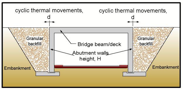
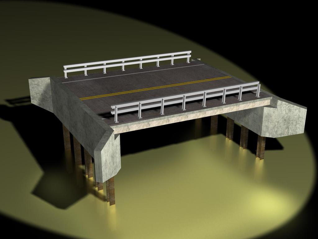
2 TYPES OF ABUTMENTS Sixteenth edition of the AASHTO (1996) standard specification classifies abutments into four types: o Stub abutments, o partial-depth abutments, o full-depth abutments; and o Integral abutments. Stub Abutment Partial-Depth Abutment Partial Depth abutments are located approximately at mid-depth of the front slope of the approach embankment. The higher backwall and wingwalls may retain fill material, or the embankment slope may continue hehind the backwall. In the latter case, a structural approach slab or end span desing must bridge the space over the fill slope and curtain walls are provided to close off the open area
3 Full-Depth Abutment Integral Abutment
4 Peck, Hanson Thornburn Classification A gravity abutment with wing walls is an abutment that consists of a bridge seat, wing walls, back wall, and footing. Gravity Abutment with Wing Walls A U-abutment is an abutment whose, wing walls are perpendicular to the bridge seat U Abutment
5 Spill Through Abutment Spill-through abutment consists of a beam that supports the bridge seat, two or more columns supporting the beam, and a footing supporting the columns. The columns are embedded up to the bottom of the beam in the fill, which extends on its natural slope in front of the abutment. Pile Bent Abutment Pile-bent abutments. A pile-bent abutment with stub wings is another type of spill-through abutment, where a row of driven piles supports the beam.
6 Other Types of Abutments
7
8 SELECTION OF ABUTMENTS: The procedure of selecting the most appropriate type of abutments can be based on the following consideration: 1. Construction and maintenance cost 2. Cut or fill earthwork situation 3. Traffic maintenance during construction 4. Construction period 5. Safety of construction workers 6. Availability and cost of backfill material 7. Superstructure depth 8. Size of abutment 9. Horizontal and vertical alignment changes 10. Area of excavation 11. Aesthetics and similarity to adjacent structures 12. Previous experience with the type of abutment 13. Ease of access for inspection and maintenance. 14. Anticipated life, loading condition, and acceptability of deformations.
9 LIMIT STATES When abutments fail to satisfy their intended design function, they are considered to reach limit states. Limit states can be categorized into two types: 1) ULTIMATE LIMIT STATES. An abutment reaches an ultimate limit state when: i.) The strength of a least one of its components is fully mobilized or ii.) The structure becomes unstable. In the ultimate limit state an abutment may experience serious distress and structural damage, both local and global. In addition, various failure modes in the soil that supports the abutment can also be identified. These are also called ultimate limit states, they include bearing capacity failure, sliding, overturning, and overall instability. 2) SERVICEABILITY LIMIT STATES. An abutment experiences a serviceability limit state when it fails to perform its intended design function fully, due to excessive deformation or deterioration. Serviceability limit states include excessive total or differential settlement, lateral movement, fatigue, vibration, and cracking.
10 LOAD AND PERFORMANCE FACTORS The AASHTO (1990) bridge specifications require the use of the load and resistance factor design (LRFD) method in the substructure design. A mathematical statement of LRFD can be expressed as i) Load Factors : Load factors are applied to loads to account for uncertainties in selecting loads and load effects. The load factors used in the first edition of the AASHTO (1994) LRFD bridge specifications are shown in Tables 3.1 and 3.2. of the Text. ii) Performance Factors: Performance or resistance factors are used to account for uncertainties in structural properties, soil properties, variability in workmanship, and inaccuracies in the design equations used to estimate the capacity. These factors are
11 used for design ate the ultimate limit state suggested values of performance factors for shallow foundations are listed in table 10.2
12 FORCES ON ABUTMENTS Earth pressures exerted on an abutment can be classified according to the direction and the magnitude of the abutment movement. 1) At-rest Earth Pressure When the wall is fixed rigidly and does not move, the pressure exerted by the soil on the wall is called at-rest earth pressure. 2) Active Earth Pressure : When a wall moves away from the backfill, the earth pressure decreases (active pressure) 3) Passive Earth Pressure When it moves toward the backfill, the earth pressure increases (passive pressure). Table 10.3, obtained through experimental data and finite element analyses (Clough and Duncan, 1991), gives approximate magnitudes of wall movements required to reach minimum active and maximum passive earth pressure conditions. Observation
13
14 1. The required movements for the extreme conditions are approximately proportional to the wall height. 2. The movement required to reach the maximum passive pressure is about 10 times as great as that required to reach the minimum active pressure for walls of the same height. 3. The movement required to reach the extreme conditions for dense and incompressible soils is smaller than those for loose and compressible soil. For any cohesionless backfill, conservative and simple guidelines for the maximum movements required to reach the extreme cases are provided by Clough and Duncan (1991). For minimum active pressure, the movements no more than about 1 mm in 240 mm ( /H = 0.004) and for maximum passive pressure about 1 mm in 24 mm ( /H = 0.004). As shown in figure 10.10: The value for the earth pressure coefficient varies with wall displacement and eventually remains constant after sufficiently large displacements. The change of pressures also varies with the type of soil, that is, the pressures in the dense sand change more quickly with wall movement.
15
16
17 METHODS FOR ESTIMATING K A AND K P Coulomb in 1776 and Rankine in 1856 developed simple methods for calculating the active and passive earth pressures exerted on retaining structures. Caquot and Kerisel (1948) developed the more generally applicable log spiral theory, where the movements of walls are sufficiently large so that the shear strength of the backfill soil is fully mobilized, and where the strength properties of the backfill can be estimated with sufficient accuracy, these methods of calculation are useful for practical purposes. Coulomb s trial wedge method can be used for irregular backfill configurations and Rankine s theory and the log spiral analysis can be used for more regular configurations. Each of these methods will be discussed below. COULOMB THEORY: The coulomb theory, the first rational solution to the earth pressure problem, is based on the concept that the lateral force exerted on a wall by the backfill can be evaluated by analysis of the equilibrium of a wedge-shaped mass of soil bounded by the back of the wall, the backfill surface, and a surface of sliding through the soil. The assumptions in this analysis are 1. The surface of sliding through the soil is a straight line. 2. The full strength of the soil is mobilized to resist sliding (shear failure) through the soil. i) Active Pressure: A graphical illustration for the mechanism for active failure according to the coulomb theory is shown in Figure 10.12a. The active earth pressure force can be expressed as:
18
19 Passive Pressure: The coulomb theory can be used to evaluate passive resistance, using the same basic assumptions. Figure 10.12b shows the failure mechanism for the passive case. The passive earth pressure force, Pp. can be expressed as follows:
20 The basic assumption in the coulomb theory is that the surface of sliding is a plane. This assumption does not affect appreciably the accuracy for the active case. However, for the passive case, values of pp calculated by the coulomb theory can be much larger than can actually be mobilized, especially when the value of δ exceeds about one half of ϕ f. Wall Friction:friction between the wall and backfill has an important effect on the magnitude of earth pressures and an even more important effect on the direction of the earth pressure force. Table 10.4 presents values of the maximum possible wall friction angle for various wall materials and soil types.
21 RANKINE THEORY: The Rankine theory is applicable to conditions where the wall friction angle (ϕ) is equal to the slope of the backfill surface (I). As in the case of the coulomb theory, it is assumed that the strength of the soil is fully mobilized. Table 10.4
22 i) Active Pressure: The active earth pressure considered in the Rankine theory is illustrated in Figure a for a level backfill condition. The coefficient of active earth pressure, k a, can be expressed as: When the ground surface is horizontal, that is, when I =0, ka expressed as can be The variation of active pressure with depth is linear, as shown in figure 10.13b. If the backfill is cohesive, the soil is theoretically in a tension zone down to a depth of 2c/γ(k a ) 2. However, a tension crack is likely to develop in that zone and may be filled with water, so that hydrostatic pressure will be exerted on the wall, as shown in figure 10.13c. ii) Passive Pressure: The Rankine theory can also be applied to passive pressure conditions. The pasive earth pressure coefficient (kp) can be expressed as
23
24 Fig10.13
25 LOG SPIRAL ANALYSIS: The failure surface in most cases is more closely approximated by a log spiral than a straight line, as shown in figure Active and passive pressure coefficients, Ka and kp obtained from analysis using log spiral surfaces are listed in tables 10.5and 10.6 (Caquot and Kerisel, 1948). Values of Ka and k p for walls with level backfill and vertical stem also shown in figure These values are also based on the log spiral analyses performed by Caquot and Kerisel.
26
27
28
29 SELECTION OF EARTH PRESSURE COEFFICIENTS: Selecting a proper earth pressure coefficient is essential for successful wall design. A number of methods previously discussed can be used to decide the magnitude of the coefficients. A decision on what type of earth pressure coefficient should be used is based on the direction and the magnitude of the wall movement. The New Zealand Ministry of Works and Development (NAMWD, 1979) has recommended the following static earth pressure coefficients for use in design: 1. Counterfort or gravity walls founded on rock or piles: K Cantilever walls less than 1880-mm high founded on rock or piles: (K0 + Ka)/2. 3. Cantilever walls higher than 4880-mm or any wall founded on a spread footing: Ka. LOCATION OF HORIZONTAL RESULTANT: In conventional designs and analyses, the horizontal resultant is assumed to be located at one-third of total height from the bottom of the wall. However, several experimental tests performed by researchers conclude that the resultant is applied at 0.40H to 0.45H from the bottom of the wall where H is the total height of the wall. EQUIVALENT FLUID PRESSURE: Equivalent fluid pressures provide a convenient means of estimating design earth pressures, especially when the backfill material is a clayey soil. The lateral earth pressure at depth z can be expressed as
30 Some typical equivalent fluid unit weights and corresponding pressure coefficients are presented in Table These are appropriate for use in designing walls up to about 6100mm in height. Values are presented for at rest condition and for walls that can tolerate movements of 1mm in 240mm, and for level and sloped backfill. When the equivalent fluid pressure is used in the estimation of horizontal earth pressure it is necessary to include vertical earth pressure acting on the wall to avoid an assumption that is too conservative. In the level backfill, the amount of the vertical earth pressure acting on the wall can be taken as much as 10% of the soil weight.
31 Effect of Surcharges: When vertical loads act on a surface of the backfill near a retaining wall or an abutment, the lateral and vertical earth pressure used for the design of the wall should be increased. Uniform Surcharge Load: A surcharge load uniformly distributed over a large ground surface area increases both the vertical and lateral pressures. The increase in the vertical pressure, P v is the same as the applied surcharge pressure, qs. that is, Pv = qs and the amount of increase in the lateral pressure, Ph is Ph = kqs Where k = an earth pressure coefficient (dimensionless) k = ka for active pressure k = k0 for at-rest condition k = k p for passive pressure Because the applied area is infinitely large, the increases in both vertical and horizontal pressures are constant over the height of the
32 wall. Therefore, the horizontal resultant force due to a surcharge load is located at mid height of the wall. Point Load and Strip Loads: The theory of elasticity can be used to estimate the increased earth pressures induced by various types of surcharge loads. Equations for earth pressures due to point load and strip loads are presented in Figure
33
34 EQUIVALENT HEIGHT OF SOIL FOR LIVE LOAD SURCHARGE: In the AASHTO (1994) LRFD Bridge Specifications, the live load surcharge, LS, is specified in terms of an equivalent height of soil, h eq, representing the vehicular loading. The values specified for heq with the height of the wall and are given in Table 10.8.
35 DESIGN REQUIREMENTS FOR ABUTMENTS Failure Modes for Abutments: Abutments are subject to various limit states or types of failure, as illustrated in figure Failures can occur within soils or the structural members. i) Sliding failure occurs when the lateral earth pressure exerted on the abutment exceeds the frictional sliding capacity of the foundation. ii) If the bearing pressure is larger than the capacity of the foundation soil or rock, bearing failure results. iii) Deep-seated sliding failure may develop in clayey soil. iv) Structural failure also should be checked.
36
37 BASIC DESIGN CRITERIA FOR ABUTMENTS: For design purposes, abutments on spread footings can be classified into three categories (Duncan et al 1990). 1. Abutment with clayey soils in the backfill or foundations. 2. Abutment with granular backfill and foundations of sand or gravel. 3. Abutment with granular backfill and foundations on rock. For each category, design procedures and stability criteria for the ASD method and the LRFD method are summarized in Figures
38
39
40
41 PROCEDURE FOR DESIGN OF ABUTMENTS: A series of steps must be followed to obtain a satisfactory design. STEP 1: SELECT PRELIMINARY PROPORTIONS OF THE WALL. STEP 2: DETERMINE LOADS AND EARTH PRESSURES. STEP 3: CALCULATE MAGNITUDE OF REACTION FORCES ON BASE. STEP 4: CHECK STABILITY AND SAFETY CRITERIA a. Location of normal component of reactions. b. Adequacy of bearing pressure. c. Safety against sliding. STEP 5: REVISE PROPORTIONS OF WALL AND REPEAT STEPS 2-4 UNTIL STABILITY CRITERIA IS SATISFIED AND THEN CHECK a. Settlement within tolerable limits. b. Safety against deep-seated foundation failure. STEP 6: IF PROPORTIONS BECOME UNRESONABLE, CONSIDER A FOUNDATION SUPPORTED ON DRIVEN PILES OR DRILLED SHAFTS. STEP 7: COMPARE ECONOMICS OF COMPLETED DESIGN WITH OTHER SYSTEMS.
42 STEP 1: SELECT PRELIMINARY PROPORTIONS OF THE WALL. figure shows commonly used dimensions for a gravity-retaining wall and a cantilever wall. These proportions can be used when scour is not a concern to obtain dimensions for a first trial of the abutment.
43 STEP 2: DETERMINE LOADS AND EARTH PRESSURES. Design loads for abutments are obtained by using group load combinations described in Tables 3.1 and 3.2. Methods for calculating earth pressures exerted on the wall are discussed in section the use of equivalent fluid pressures presented in table 10.7 gives satisfactory earth pressures if conditions are no unusual. STEP 3: CALCULATE MAGNITUDE OF REACTION FORCES ON BASE. Figure illustrates a typical cantilever wall subjected to various loads causing reaction forces which are normal to the base (N) and tangent to the base (Fr). These reaction forces are determined by simple static for each load combination being investigated.
44
45 STEP 4: CHECK STABILITY AND SAFETY CRITERIA a. Location of normal component of reactions. b. Adequacy of bearing pressure. c. Safety against sliding. 1. The location of the resultant on the base is determined by balancing moments about the toe of the wall. The criteria for foundation on soil for the location of the resultant is that it must lie within the middle half for LRFD (Figs and 10.19). This criterion replaces the check on the ratio of stabilizing moment to overturning moment. For foundations on rock, the acceptable location of the resultant has a greater range than for foundations on soil Middle three quarters of base As shown in figure 10.23, the location of the resultant, X0, is obtained by X0 = (Summation of moments about point o) / N Where N = the vertical resultant force (force/length). The eccentricity of the resultant, e, with respect to the centerline of the base is e = B/2 X 0 where B = base width (length)
46 2. Safety against bearing failure is obtained by applying a performance factor to the ultimate bearing capacity in the LRFD method. The ultimate BC can be calculated from the in-situ tests or semiemperical procedures. Safety against bearing failure is checked by φri qult qumax qult = ultimate BC (force/length) RI = reduction factor due to inclined loads = (1 Hn/Vn) 3 Hn = unfactored horizontal force Vn = unfactored vertical force φ = performance or resistance factor qmax = maximum bearing pressure due to factored loads (force/length 2 ) Shape of Bearing Pressure Distribution: The resultant, N, will pass through the centered of a triangular or trapezoidal stress distribution, or the middle of a uniformly distributed stress block. Maximum Bearing Pressure: The following equations are used to compute the max. soil pressures, q umax per unit length of a rigid footing. For a triangular shape of bearing pressure: When the resultant is within the middle third of base q umax = Nu / B 6 N(u) e / B2 When the resultant is outside of the middle third of base q umax = 2 N(u) / 3 Xo
47 For a uniform distribution of the bearing pressure qumax = N(u) / 2Xo Where N(u) = unfactored (factored) vertical resultant (force/length) Xo = location of the resultant measured from toe (length) e = eccentricity of N(u) (length)
48 fig10.23
49 3. In the LRFD method, sliding stability is checked by φs Fru γi Phi where φs = performance factor for sliding (values given in tab 10.2) Fru = N(u) tan δb + c a Be Nu = factored vertical resultant δb = friction angle b/w base and soil ca = adhesion (force /length 2 ) Be = effective length of base in compression γ i = load factor for force component i Phi = horizontal earth pressure force i causing sliding (force/length) The passive earth pressure generated by the soil in front of the wall may be included to resist sliding if it is ensured that the soil in front of the wall will exist permanently. However, sliding failure occurs in many cases before the passive earth pressure is fully mobilized. Therefore, it is safer to ignore the effect of the passive earth pressure.
50 STEP 5: REVISE PROPORTIONS OF WALL AND REPEAT STEPS 2-4 UNTIL STABILITY CRITERIA IS SATISFIED AND THEN CHECK a. Settlement within tolerable limits. b. Safety against deep-seated foundation failure. When the preliminary wall dimensions are found inadequate the wall dimensions should be adjusted by a trial an error method. A sensitivity study done by Kim shows that the stability can be improved by varying the location of the wall stem, the base width, and the wall height. Some suggestions for correcting each stability or safety problems are presented as follows: 1. Bearing failure or eccentricity criterion not satisfied a. Increase the base width. b. Relocate the wall stem by moving towards the heel. c. Minimize Ph by replacing a clayey backfill with granular material or by reducing pore water pressure behind the wall stem with a well designed drainage system. d. Provide an adequately designed reinforced concrete approach slab supported at one end by the abutment so that no horizontal pressure due to live load surcharge need be considered. 2. Sliding stability criteria not satisfied a. Increase the base width b. Minimize Ph as described above c. Use an inclined base (heel side down) to increase horizontal distance. d. Provide an adequately designed approach slab mentioned above. e. Use a shear key 3. Settlement and Overall Stability Check. Once the proportions of the wall have been selected to satisfy the bearing pressure, eccentricity, and sliding criteria then the requirements on settlement and overall slope stability must be checked.
51 a. Settlement should be checked for walls founded on compressible soils to ensure that the predicted settlement is less than the settlement than the wall or structure it supports can tolerate. The magnitude of settlement can be estimated using the methods described in the Engineering manual for shallow foundations. b. The overall stability of slopes with regard to the most critical sliding surface should be evaluated if the wall is underlain by week soil. This check is based on limiting equilibrium methods, which employ the modified Bishop, simplified Janbu or Spenser analysis. STEP 6: IF PROPORTIONS BECOME UNRESONABLE, CONSIDER A FOUNDATION SUPPORTED ON DRIVEN PILES OR DRILLED SHAFTS. Driven piles and drilled shafts can be used when the configuration of the wall is unreasonable or uneconomical. STEP 7: COMPARE ECONOMICS OF COMPLETED DESIGN WITH OTHER SYSTEMS. When a design is completed, it should be compared with other types of walls that may result in a more economical design.
52 Example : Abutment design Using LRFD method, the stability and safety for the abutment below is to be checked. The abutment is found on sandy gravel with an average SPT blow count of 22. The ultimate bearing capacity (10 tons/sft).
53 DETERMINATION OF LOADS AND EARTH PRESSURES Loadings: The loadings from the superstructure are given as DL= dead load = kn / m LL= live load = 87.5 kn / m WS= wind load on superstructure = 2.9 kn / m WL = wind load on superstructure = 0.7 kn / m BR= 3.6 kn / m CR +SH+TU = creep, shrinkage, and temperature = 10% of DL = 10.9 kn / m Pressures generated by the live load and dead load surcharges can be obtained as ω L = h eq γ = 1195 mm x 18.9 kn / m 3 = 22.6 kn / m 2 ωd = (slab thickness) γc = 305 mm x 23.6 kn / m 3 = 7.2 kn / m 2 HL = K ωl H = 0.25 x 22.6 kn / m 2 x 2743 mm = kn / m HD = K ωd H = 0.25 x 7.2 kn / m 2 x 2743 mm = 4.94 kn / m VL = ωl * (heel width) = 22.6 kn / m 2 x 380 mm = 8.59 kn / m VD = ωd * (heel width) = 7.2 kn / m 2 x 380 mm = 2.74kN / m Pressures due to equivalent fluid pressure can be calculated as P h = ( ½ )(EFP h ) H 2 = ( ½ )(5.50)(2.745) 2 = kn / m Pv= ( ½ )(EFPv H 2 = ( ½ )(1.89)(2.745) 2 = 7.12 kn / m
54
55
56
57
58
Earthquake Resistance of Bridges With Friction Slab Abutments
 Earthquake Resistance of s With Friction Slab Abutments J. H. Wood John Wood Consulting, Lower Hutt. ABSTRACT: 2010 NZSEE Conference Findings from experimental and numerical research on the force resistance
ASD and LRFD of Reinforced SRW with the use of software Program MSEW(3.0)
") ASD and LRFD of Reinforced SRW with the use of software Program MSEW(3.0) Dov Leshchinsky [A slightly modified version of this manuscript appeared in Geosynthetics (formerly GFR), August 2006, Vol. 24,
ASD and LRFD of Reinforced SRW with the use of software Program MSEW(3.0) Dov Leshchinsky [A slightly modified version of this manuscript appeared in Geosynthetics (formerly GFR), August 2006, Vol. 24,
PRELIMINARY GEOTECHNICAL DESIGN
 PNCC Manawatu River Pedestrian/ Cycle Bridge PRELIMINARY GEOTECHNICAL DESIGN 1 Introduction Opus has been commissioned by the Palmerston North City Council (PNCC) to prepare a Detailed Business Case (DBC)
Low-Volume Road Abutment Design Standards
 Low-Volume Road Abutment Design Standards V.W. Robbins HNTB Corporation 7450 W. 130th St., Suite 400 Overland Park, KS 66213 vrobbins@hntb.com F. Wayne Klaiber Bridge Engineering Center 418 Town Engineering
Development of Preflex Composite Beam-Stub Abutment Integral Bridge System
 Steel Structures 6 (2006) 175-181 www.kssc.or.kr Development of Preflex Composite Beam-Stub Abutment Integral Bridge System Jae-Ho Jung 1, Won-Sup Jang 1, Sung-Kun You 2, Young-Ho Kim 2 and Soon-Jong Yoon
DATA GATHERING AND DESIGN DETAILS OF AN INTEGRAL ABUTMENT BRIDGE
 DATA GATHERING AND DESIGN DETAILS OF AN INTEGRAL ABUTMENT BRIDGE Abstract S. Hassiotis M. ASCE Stevens Institute of Technology, Hoboken, N.J. 07030 sophia.hassiotis@stevens.edu An integral-abutment bridge
Integral Abutment Bridges-Development of Soil Model for Soil Structure Interaction in Time History Analysis
 International Journal of Engineering Research and Development e-issn: 2278-067X, p-issn: 2278-800X, www.ijerd.com Volume 10, Issue 3 (March 2014), PP.31-40 Integral Abutment Bridges-Development of Soil
Technology. Reinforced Earth Wall Typical Section. Traffic Barrier. Roadway. Select Granular Material. Facing Panel Random Backfill.
 Bridge Applications Technology The Reinforced Earth Company (RECo) offers a variety of bridge abutment and bridge crossing solutions, each are based on project specific requirements. Bridge abutments are
Integral Abutment Bridge Design with Soil Structure Interaction
 Integral Abutment Bridge Design with Soil Structure Interaction Thursday, May 11, 2017 3:00 PM 4:00 PM EST Speaker Engineer: Suthichai Saelim Project Location WESTBOROUGH Railroad HOPKINTON Project Location
Integral bridges and environmental conditions
 Integral bridges and environmental conditions COMISU CLAUDIU-CRISTIAN, BOACĂ GHEORGHITĂ Department of Roads and Foundations Faculty of Civil Engineering and Building Services The "Gheorghe Asachi" Technical
A Tale of Two Bridges: Comparison between the Seismic Performance of Flexible and Rigid Abutments
 A Tale of Two Bridges: Comparison between the Seismic Performance of Flexible and Rigid Abutments A.M. Morsy. Department of Civil, Architectural, and Environmental Engineering, The University of Texas
CHAPTER 5 MODELING OF THE BRIDGE
 62 CHAPTER 5 MODELING OF THE BRIDGE 5.1 MODELING SAP2000, a nonlinear software package was used for modeling and analysing the study bridge. The following list provides details about the element type used
Pennsylvania s Experience with LRFD Implementation. By: Thomas Macioce, P.E. Beverly Miller, P.E. Pennsylvania Department of Transportation
 Pennsylvania s Experience with LRFD Implementation By: Thomas Macioce, P.E. Beverly Miller, P.E. Pennsylvania Department of Transportation Overview Case History Spread Footing Width and Braking force Approach
Design of Dingley Bypass Integral Bridges
 Design of Dingley Bypass Integral Bridges Dr. Kabir Patoary Principal Engineer Bridges GHD Elder St South Underpass Tekla Model Presentation Outline 1. Overview of Dingley Bypass 2. Design of Integral
Semi-Integral Abutment Bridges
 Ministry of Transportation Report BO-99-03 Bridge Office Leslie Street Over Hwy 407 Semi-Integral Abutment Bridges Ministry of Transportation Report BO-99-03 Bridge Office Semi-Integral Abutment Bridges
Integral Bridge Design - Derivation of the Spring Constant for Modelling the Soil-Structure Interaction
 Integral Bridge Design - Derivation of the Spring Constant for Modelling the Soil-Structure Interaction Sergei Terzaghi BE(Hons), MIPENZ Gillian Sisk BEng PhD MIEI CEng Synopsis Integral bridges present
EFFECT OF BACKFILL SOIL TYPE ON STIFFNESS AND CAPACITY OF BRIDGE ABUTMENTS
 EFFECT OF BACKFILL SOIL TYPE ON STIFFNESS AND CAPACITY OF BRIDGE ABUTMENTS A. Bozorgzadeh 1, S. A. Ashford 2, and J. I. Restrepo 3 1 PhD, Structural Engineering, Moffatt and Nichol Inc, Walnut creek, CA,
Numerical analysis of the embedded abutments of integral bridges
 Numerical analysis of the embedded abutments of integral bridges Ming XU Researcher, Dept. of Civil & Env. Engrg., University of Southampton, UK Summary Alan G. BLOODWORTH Lecturer, Dept. of Civil & Env.
Permanent deformation of bridge abutment on liquefiable soils
 Permanent deformation of bridge abutment on liquefiable soils Akihiro TAKAHASHI 1, Hideki SUGITA 1 & Shunsuke TANIMOTO 1 ABSTRACT Seismic response of a bridge abutment located near a river dyke is the
Figure 3: Analytic procedure
 International Journal of Scientific and Research ublications, Volume 7, Issue 5, May 2017 567 Investigation of Integral Bridge Effect under Dynamic Loading Haymanmyintmaung *,kyawlinnhtat ** * Department
Resistance From Bridge Abutment Passive Soil Pressure in Earthquakes
 Resistance From Bridge Abutment Passive Soil Pressure in Earthquakes J. H. Wood John Wood Consulting, Lower Hutt. ABSTRACT: 2009 NZSEE Conference This paper summarises the results from recent experimental
PENNDOT e-notification
 PENNDOT e-notification Bureau of Design Engineering Computing Management Division BRADD No. 027 August 30, 2010 Release of Version 3.1.5.0 PennDOT's Bridge Automated Design and Drafting Software (BRADD)
Seismic Response of Piled Bridge Abutments in Multi-Layered Liquefiable Soils Deposits
 6 th International Conference on Earthquake Geotechnical Engineering 1-4 November 2015 Christchurch, New Zealand Seismic Response of Piled Bridge Abutments in Multi-Layered Liquefiable Soils Deposits D.
Appendix B. Shallow Foundations Report
 12/10/2013 GEOTECHNICAL MANUAL Appendix B. Shallow Foundations Report PLEASE NOTE A sample foundations report is included here for reference. It is provided as an example of content, format, and organization
3/18/03 CE Keith P. Brabant, P.E.
 1 Keith P. Brabant, P.E. 2 SELECT GRANULAR BACKFILL 3 4 Maximum of 15% fines Maximum size of 4 inches Free-draining, frictional, and durable Graduation limits referenced by AASHTO T-27 5 US Sieve Size
Development of Abutment Design Standards for Local Bridge Designs Volume 1 of 3
 F. W. Klaiber, D. J. White, T. J. Wipf, B. M. Phares, V. W. Robbins Development of Abutment Design Standards for Local Bridge Designs Volume 1 of 3 Development of Design Methodology August 2004 Sponsored
Effect of Pile Orientation in Skewed Integral Abutment Bridges
 Effect of Pile Orientation in Skewed Integral Abutment Bridges RABIH NAJIB, Ph.D., PE, Alpha Corporation, Baltimore, Maryland and AMDE M. AMDE, Ph.D., PE, University of Maryland, College Park, Maryland
Update on Seismic Behavior and Design of
 Update on Seismic Behavior and Design of Steel Plate Girder Bid Bridges Ahmad M. Itani, Ph.D., P.E., S.E. Professor Department of Civil and Environmental Engineering University of Nevada, Reno Background
EFFECTS OF SPATIAL VARIATION OF SEISMIC INPUTS ON BRIDGE LONGITUDINAL RESPONSE
 13 th World Conference on Earthquake Engineering Vancouver, B.C., Canada August 1-6, 24 Paper No. 64 EFFECTS OF SPATIAL VARIATION OF SEISMIC INPUTS ON BRIDGE LONGITUDINAL RESPONSE Jiachen WANG 1, Athol
Modified Sheet Pile Abutment for Low-Volume Road Bridge
 Modified Sheet Pile Abutment for Low-Volume Road Bridge Ryan R. Evans Department of Civil, Construction, and Environmental Engineering Iowa State University 176 Town Engineering Ames, IA 50011 ryevans@iastate.edu
Seismic Analysis of Bridge Abutment-Soil Systems
 ISSN: 2454-2377, Seismic Analysis of Bridge Abutment-Soil Systems M. G. Mahamuni 1* & Dr. S. K. Kulkarni 2 1 Post Graduate Student, Civil Engineering Department, Dr. D.Y. Patil School of Engg and Tech,
Design Considerations for Integral Abutment/ Jointless Bridges in the USA
 University of Wisconsin Milwaukee UWM Digital Commons Civil and Environmental Engineering Faculty Articles Civil and Environmental Engineering 3-2014 Design Considerations for Integral Abutment/ Jointless
Appendix C Guidelines for Design of Integral Abutments March 3, 2003
 These guidelines draw on the experiences and practices from Ontario, the FHWA, various DOT s and the UK Highways Agency. They provide guidance and outline the issues that need to be considered and should
SUMMARY OF NOVEMBER 2013 REVISIONS - VERSION
 SUMMARY OF NOVEMBER 2013 REVISIONS - VERSION 3.2.0.0 Since the release of BRADD Version 3.1.6.2, several major enhancements have been made to the software and many reported operational issues have been
Three Bridges at I-64/Mercury Boulevard Interchange in Hampton, VA
 Three Bridges at I-64/Mercury Boulevard Interchange in Hampton, VA IRFAN A. ALVI, P.E., Alvi Associates, Inc., Baltimore, MD IBC-02-25 KEYWORDS: box girder, counterweight abutment, curved girder, high-performance
Introduction. Substructure Inspection and Rating. Introduction. Introduction 28/03/2017
 Introduction Substructure Inspection and Rating That portion of the bridge located below the bearings Abutments Piers Rated separately Purpose is to: Receive the loads from the superstructure Transfer
Thermal Response of a Highly Skewed Integral Bridge
 Thermal Response of a Highly Skewed Integral Bridge http://www.virginiadot.org/vtrc/main/online_reports/pdf/12-r10.pdf EDWARD J. HOPPE, Ph.D., P.E. Senior Research Scientist SETH L. EICHENTHAL Research
Monitored Displacements of a Unique Geosynthetic-Reinforced Walls Supporting Bridge and Approaching Roadway Structures
 Abu-Hejleh, N., Zornberg, J.G., and Wang, T. (). Monitored Displacements of a Unique Geosynthetic-Reinforced Walls Supporting Bridge and Approaching Roadway Structures. Proceedings of the 8th Annual Meeting,
2011 BRIDGE INSPECTION REPORT
 2011 BRIDGE INSPECTION REPORT BYRD PARK PUMP STATION BRIDGE OVER KANAWHA CANAL April 2011 FINAL December 2011 Looking - from Abutment B to Abutment A Prepared by: WHITMAN, REQUARDT, & ASSOCIATES, LLP 9030
PERFORMANCE OF REINFORCED EARTH BRIDGE ABUTMENT WALLS IN THE CANTERBURY EARTHQUAKES
 PERFORMANCE OF REINFORCED EARTH BRIDGE ABUTMENT WALLS IN THE 2010-2011 CANTERBURY EARTHQUAKES John H Wood 1 and Donald E Asbey-Palmer 2 SUMMARY Reinforced Earth bridge abutment walls were subjected to
SEEPAGE ANALYSIS OF TWO CASE HISTORIES OF PIPING INDUCED BY EXCAVATIONS IN COHESIONLESS SOILS
 ICCI2004, The First International Conference on Construction IT, Beijing, CHINA, August 12 th - 14 th SEEPAGE ANALYSIS OF TWO CASE HISTORIES OF PIPING INDUCED BY EXCAVATIONS IN COHESIONLESS SOILS Cai,
Grade separated interchange at the intersection of U.S. Hwy 17 Bypass and Farrow Parkway
 Grade separated interchange at the intersection of U.S. Hwy 17 Bypass and Farrow Parkway Jeff Sizemore, P.E. Geotechnical Design Support Engineer SCDOT Ed Tavera, P.E. Principal Geotechnical Engineer Geoengineers
The UCD community has made this article openly available. Please share how this access benefits you. Your story matters!
 Provided by the author(s) and University College Dublin Library in accordance with publisher policies., Please cite the published version when available. Title Reduction of lateral loads in abutments using
APPENDIX A INTEGRAL ABUTMENTS
 APPENDIX A INTEGRAL ABUTMENTS Appendix A Guidelines for Design of Integral Abutments Rev. 1 - September, 2007 These guidelines draw on the experiences and practices from Ontario, the FHWA, various DOT
BEHAVIOR AND ANALYSIS OF AN INTEGRAL ABUTMENT BRIDGE
 BEHAVIOR AND ANALYSIS OF AN INTEGRAL ABUTMENT BRIDGE Paul J. Barr Marv W. Halling Conner Huffaker Hugh Boyle Utah State University Department of Civil and Environmental Engineering Logan, Utah September
research report Field Measurements on Skewed Semi-Integral Bridge With Elastic Inclusion: Instrumentation Report
 Final Report VTRC 06-R35 Virginia Transportation Research Council research report Field Measurements on Skewed Semi-Integral Bridge With Elastic Inclusion: Instrumentation Report http:/www.virginiadot.org/vtrc/main/online_reports/pdf/06-r35.pdf
Numerical Modeling of the Performance of Highway Bridge Approach Slabs. Gregory S. Rajek
 Numerical Modeling of the Performance of Highway Bridge Approach Slabs by Gregory S. Rajek A thesis in partial fulfillment of the requirements for the degree of Master of Science (Civil Engineering) UNIVERSITY
DESIGN ASSESSMENT OF THE FOUNDERS/MEADOWS GRS ABUTMENT STRUCTURE
 Abu-Hejleh, N., Zornberg, J.G., Elias, V., and Watcharamonthein, J. (23). Design Assessment of the Founders/Meadows GRS Abutment Structure. Proceedings of the 82nd Annual Meeting of the Transportation
APPENDIX A - THE BEHAVIOR OF INTEGRAL ABUTMENT BRIDGES
 APPENDIX A - THE BEHAVIOR OF INTEGRAL ABUTMENT BRIDGES Report submitted to VTRC in November, 1999 THE BEHAVIOR OF INTEGRAL ABUTMENT BRIDGES FINAL CONTRACT REPORT Sami Arsoy, Richard M. Barker, and J. Michael
Earthquake Design of Bridges With Integral Abutments
 6 th International Conference on Earthquake Geotechnical Engineering 1-4 November 2015 Christchurch, New Zealand Earthquake Design of Bridges With Integral Abutments J. H. Wood 1 ABSTRACT Because of the
Geosynthetic-reinforced soil bridge abutments
 Geosynthetic-reinforced soil bridge abutments Measuring the performance of geosynthetic reinforcement in a Colorado bridge structure. By Jorge G. Zornberg, Naser Abu-Hejleh, and Trever Wang The technology
UNDERWATER BRIDGE INSPECTION REPORT STRUCTURE NO CRANE LAKE ROAD OVER HAWKINSON CREEK ST. LOUIS COUNTY
 UNDERWATER BRIDGE INSPECTION REPORT STRUCTURE NO. 7883 CRANE LAKE ROAD OVER HAWKINSON CREEK ST. LOUIS COUNTY JUNE 21, 2012 PREPARED FOR THE MINNESOTA DEPARTMENT OF TRANSPORTATION BY COLLINS ENGINEERS,
Bahavior and Analysis of an Integral Abutment Bridge
 Utah State University DigitalCommons@USU All Graduate Theses and Dissertations Graduate Studies 2013 Bahavior and Analysis of an Integral Abutment Bridge Conner D. Huffaker Follow this and additional works
Shifting the Canning Bus Bridge Sideways
 Shifting the Canning Bus Bridge Sideways Ros MacKinlay Design Engineer, Wyche Consulting SYNOPSIS The Perth Mandurah railway proposed in 2002 required the replacement of an existing Kwinana Freeway bus
Four simply supported steel plate girders (appear to be an old railcar).
.") BRIDGE INSPECTION BRIDGE NO./NAME N4-005: Akolkolex Crawford FSR (19.0 km) Inspection Date: September 22 nd, 2012 Inspected By: M. Hanson, R. Veitch Year Built: 1982 Number of Spans: 1 Span Lengths: Superstructure
BRIDGE INSPECTION BRIDGE NO./NAME N4-005: Akolkolex Crawford FSR (19.0 km) Inspection Date: September 22 nd, 2012 Inspected By: M. Hanson, R. Veitch Year Built: 1982 Number of Spans: 1 Span Lengths: Superstructure
SUMMARY OF NOVEMBER 2018 REVISIONS - VERSION
 SUMMARY OF NOVEMBER 2018 REVISIONS - VERSION 3.2.5.0 Since the release of BRADD Version 3.2.4.3, several operational issues have been addressed. This release of BRADD Version 3.2.5.0 contains the following
Emergency Bridge Stabilization at Mile Watrous Subdivision
 Emergency Bridge Stabilization at Mile 189.70 Watrous Subdivision Christophe Deniaud, Ph.D., P.Eng. Bridge Engineer, CN 10004-104 Avenue Edmonton, Alberta, Canada T5J 0K2 Tel: (780) 421-6021 Fax: (780)
ACCELERATED BRIDGE CONSTRUCTION PROJECT: THE REPLACEMENT OF MD 362 OVER MONIE CREEK
 ACCELERATED BRIDGE CONSTRUCTION PROJECT: THE REPLACEMENT OF MD 362 OVER MONIE CREEK Joseph Navarra, P.E, Maryland State Highway Administration, 410-545-8315, jnavarra@sha.state.md.us ABSTRACT The MDSHA
UNDERWATER BRIDGE INSPECTION REPORT STRUCTURE NO CSAH NO. 4 OVER THE CLEARWATER RIVER (DAM) DISTRICT 2 - CLEARWATER COUNTY
 DISTRICT 2 - CLEARWATER COUNTY") UNDERWATER BRIDGE INSPECTION REPORT STRUCTURE NO. 4992 CSAH NO. 4 OVER THE CLEARWATER RIVER (DAM) DISTRICT 2 - CLEARWATER COUNTY PREPARED FOR THE MINNESOTA DEPARTMENT OF TRANSPORTATION BY COLLINS ENGINEERS,
UNDERWATER BRIDGE INSPECTION REPORT STRUCTURE NO. 4992 CSAH NO. 4 OVER THE CLEARWATER RIVER (DAM) DISTRICT 2 - CLEARWATER COUNTY PREPARED FOR THE MINNESOTA DEPARTMENT OF TRANSPORTATION BY COLLINS ENGINEERS,
Geotechnical Issues Associated With the Design and Construction of the Middle River Bridge
 Missouri University of Science and Technology Scholars' Mine International Conference on Case Histories in Geotechnical Engineering (2013) - Seventh International Conference on Case Histories in Geotechnical
Long-Term Response Prediction of Skewed Integral Bridges under Creep Effects
 From the SelectedWorks of Innovative Research Publications IRP India Winter January 1, 215 Long-Term Response Prediction of Skewed Integral Bridges under Creep Effects Innovative Research Publications,
UNDERWATER BRIDGE INSPECTION REPORT STRUCTURE NO CSAH 24 OVER HAWKINSON CREEK ST. LOUIS COUNTY
 UNDERWATER BRIDGE INSPECTION REPORT STRUCTURE NO. 7685 CSAH 24 OVER HAWKINSON CREEK ST. LOUIS COUNTY JUNE 21, 2012 PREPARED FOR THE MINNESOTA DEPARTMENT OF TRANSPORTATION BY COLLINS ENGINEERS, INC. JOB
Comparative Study of Behaviour of Integral and Bearing Type Bridge under Temperature Loading
 IJSRD - International Journal for Scientific Research & Development Vol. 3, Issue 03, 2015 ISSN (online): 2321-0613 Comparative Study of Behaviour of Integral and Bearing Type Bridge under ing B. J. Shah
Keywords: integral abutment bridge, pile head abutment connection, finite element method.
 Global Journal of Researches in Engineering: e Civil And Structural Engineering Volume 15 Issue 1 Version 1.0 Year 2015 Type: Double Blind Peer Reviewed International Research Journal Publisher: Global
300 GEORGE ST REDEVELOPMENT IMPACT OF PROPOSED BASEMENT EXCAVATION ON THE ANN STREET ONRAMP STRUCTURES
 300 GEORGE ST REDEVELOPMENT IMPACT OF PROPOSED BASEMENT EXCAVATION ON THE ANN STREET ONRAMP STRUCTURES BONACCI GROUP DOCUMENT HISTORY ISSUE REVISION DATE AUTHOR REVIEWER Issued for DTMR Review A October
UNDERWATER BRIDGE INSPECTION REPORT STRUCTURE NO th STREET OVER THE ZUMBRO RIVER CITY OF ROCHESTER
 UNDERWATER BRIDGE INSPECTION REPORT STRUCTURE NO. 89188 7 th STREET OVER THE ZUMBRO RIVER CITY OF ROCHESTER OCTOBER 2, 2012 PREPARED FOR THE MINNESOTA DEPARTMENT OF TRANSPORTATION BY COLLINS ENGINEERS,
OVER US 6 LATERAL BRIDGE SLIDE: I-75
 LATERAL BRIDGE SLIDE: I-75 OVER US 6 Bob Beasley, PE, Ohio Bridge Manager, Arcadis U.S., Inc. Todd Lezon, Regional Manager, Kokosing Construction Company, Inc. November 4, 2016 1 Agenda Design Bob Beasley,
Conditional assessment of Kiri Bridge in Shkoder, Albania
 Conditional assessment of Kiri Bridge in Shkoder, Albania Gentian Rexhaj 1, Enea Mustafaraj 2 1 2 Department of Civil Engineering, Epoka University, Albania 2 Department of Civil Engineering, Epoka University,
R-Group Finland Oy. RLS Lifting Sockets Technical Manual According to Eurocodes, EU Machinery directive 2006/42/EC and VDI/BV-BS 6205 CE Approved
 R-Group Finland Oy RLS Lifting Sockets Technical Manual According to Eurocodes, EU Machinery directive 2006/42/EC and VDI/BV-BS 6205 CE Approved 9.1.2017 2 Table of Contents 1 DESCRIPTION OF THE SYSTEM...
Bridge pile abutment deck interaction in laterally spreading ground: Lessons from Christchurch
 Bridge pile abutment deck interaction in laterally spreading ground: Lessons from Christchurch P.Tasiopoulou,E. Smyrou School of Civil Engineering, National Technical University, Athens İ.E. Bal Istanbul
Identifying Number MPC-354. Project Title: Geotechnical Limit to Scour at Spill-through Abutments. University: The University of Wyoming
 Identifying Number MPC-354 Project Title: Geotechnical Limit to Scour at Spill-through Abutments University: The University of Wyoming Principal Investigators: Robert Ettema PhD, PE College of Engineering
Executive Summary RPT-GEN November 28. Bridge No Quartz Creek Bridge Inspection Report
 Executive Summary The No. 01607 carries the Trans-Canada Highway over Quartz Creek, approximately 45 km northwest of Golden, BC. As part of an Enhanced Bridge Inspection Program, the BC Ministry of Transportation
Analyses of State Highway Bridges Damaged in the Darfield and Christchurch Earthquakes
 Analyses of State Highway Bridges Damaged in the Darfield and Christchurch Earthquakes J. H. Wood John Wood Consulting, Lower Hutt. ABSTRACT: 2012 NZSEE Conference Twelve State Highway (SH) bridges subjected
Novel treatment technique
 Final conference Zagreb, 27 th April 2018 TREAT How to choose the optimal rehabilitation technique Novel treatment technique Stanislav Lenart Slovenian National Building and Civil Engineering Institute
Flume Installation Instructions
 Flume Installation Instructions To ensure a successful installation, it is important to keep the following points in mind: 1) There should be no bend, dips, elbows, or flow junction immediately upstream
Prediction of Concrete Integral Abutment Bridge Unrecoverable Displacements
 SP-284 11 Prediction of Concrete Integral Abutment Bridge Unrecoverable Displacements WooSeok Kim, Jeffrey A. Laman, and Daniel G. Linzell Synopsis: Integral abutment bridges (IABs) have performed successfully
UNDERWATER BRIDGE INSPECTION REPORT STRUCTURE NO CSAH NO. 6 OVER A BRANCH OF THE CALDWELL CREEK DISTRICT 1 - KOOCHICHING COUNTY
 UNDERWATER BRIDGE INSPECTION REPORT STRUCTURE NO. 36508 CSAH NO. 6 OVER A BRANCH OF THE CALDWELL CREEK DISTRICT 1 - KOOCHICHING COUNTY PREPARED FOR THE MINNESOTA DEPARTMENT OF TRANSPORTATION BY COLLINS
Assessing potential cracking zones in embankment dams
 Southern Cross University epublications@scu 23rd Australasian Conference on the Mechanics of Structures and Materials 2014 Assessing potential cracking zones in embankment dams Ke He University of New
The Long Term Performance Of Skew Integral Bridges
 The Long Term Performance Of Skew Integral Bridges Popoola, Oladele.O. Civil Engineering Department Afe Babalola University Ado-Ekiti, Nigeria oladelepope@yahoo.com Wasiu, John Civil Engineering Department
The Pennsylvania State University. The Graduate School. Department of Civil and Environmental Engineering
 The Pennsylvania State University The Graduate School Department of Civil and Environmental Engineering LENGTH LIMITATIONS OF PRESTRESSED CONCRETE GIRDER INTEGRAL ABUTMENT BRIDGES A Thesis in Civil Engineering
Experimental and Analytical Investigation of UHPC Pile-to-Abutment Connections
 Experimental and Analytical Investigation of UHPC Pile-to-Abutment Connections Sriram Aaleti 1 and Sri Sritharan 2 1 Assistant Professor, Department of Civil, Construction and Environmental Engineering,
County of Orange. Presented to the Flood Division August 13, 2001 by Nadeem Majaj
 Using HECRAS TO Evaluate Scour At Bridges County of Orange Presented to the Flood Division August 3, 200 by Nadeem Majaj Approximately 575,000 bridges are built over waterways in the US. The most common
DESIGN AND CONSTRUCTION OF BR1449 VICTORIA PARK DRIVE MODIFICATIONS, BURSWOOD, WA
 DESIGN AND CONSTRUCTION OF BR1449 VICTORIA PARK DRIVE MODIFICATIONS, BURSWOOD, WA Brian Lord, Arup Pty Ltd, Australia ABSTRACT Arup was lead designer for Lend Lease on the Victoria Park Drive Modifications
Critically damaged bridges & concepts for earthquake recovery
 Critically damaged bridges & concepts for earthquake recovery J. Waldin, J. Jennings & P. Routledge Opus International Consultants Ltd, Christchurch, New Zealand 2012 NZSEE Conference ABSTRACT: This paper
EXAMINATION OF THE RESPONSE OF SKEWED STEEL BRIDGE SUPERSTRUCTURE DURING DECK PLACEMENT
 Norton et al. Word Count: 8400 Tables: 5 Figures: 13 1 EXAMINATION OF THE RESPONSE OF SKEWED STEEL BRIDGE SUPERSTRUCTURE DURING DECK PLACEMENT Date submitted: 08/01/02 Date Revised and Resubmitted: 11/15/02
Modified Sheet Pile Abutments for Low-Volume Road Bridges
 EERC Publication ERXX-XX Modified Sheet Pile Abutments for Low-Volume Road Bridges Final Report JANUARY 2012 Sponsored by Iowa Highway Research Board (IHRB Project TR-568) Iowa Department of Transportation
State-Aid Bridge News August 2, 2005
 State-Aid Bridge News August 2, 2005 Bridge Hydraulic Information The FHWA has been inquiring about our Scour Program. In particular, there are two areas of concern; 1. Are our Scour Action Plans current
The Design of Integral Bridges
 The Design of Integral Bridges AM-STR-06008 June 2014 AM Asset Management & Maintenance Standards TRANSPORT INFRASTRUCTURE IRELAND (TII) PUBLICATIONS About TII Transport Infrastructure Ireland (TII) is
Ashton Avenue Integral Bridge
 Ashton Avenue Integral Bridge Behzad Golfa, Senior Bridge Engineer, GHD Pty Ltd ABSTRACT The Ashton Avenue Bridge is a replacement of the original three-span timber bridge over Perth- Fremantle Rail line
Two-Dimensional Computer Modeling of Pomme de Terre River at Highways 12 and 22 in Minnesota
 Two-Dimensional Computer Modeling of Pomme de Terre River at Highways 12 and 22 in Minnesota Kamal Saffarinia 1, G. Kenneth Young 2, J. Sterling Jones 3, and Stuart Stein 4 This paper investigates two-dimensional
Reducing Bridge Damage Caused by Pavement Forces Part 1: Some Examples
 Reducing Bridge Damage Caused by Pavement Forces Part 1: Some Examples BY MARTIN P. BURKE, JR. Innumerable bridges both in the U.S. and abroad have been, and continue to be, damaged by the restrained growth
THERMAL RESPO SE OF I TEGRAL ABUTME T BRIDGES WITH MSE WALLS: UMERICAL A ALYSES A D A PRACTICAL A ALYSIS TOOL
 THERMAL RESPO SE OF I TEGRAL ABUTME T BRIDGES WITH MSE WALLS: UMERICAL A ALYSES A D A PRACTICAL A ALYSIS TOOL Alfredo E. Arenas Dissertation submitted to the faculty of the Virginia Polytechnic Institute
Bengt H. Fellenius. Wick Drains and Piling for Cai Mep Container Port, Vietnam, and the true cost of 5 cent per foot. Amsterdam.
 Wick Drains and Piling for Cai Mep Container Port, Vietnam, and the true cost of 5 cent per foot Bengt H. Fellenius Amsterdam May 27, 216 Fellenius, B.H. and Nguyen, M.H., 213. Wick Drains and Piling for
Rebuilding and widening the 54- year-old Jane Addams Memorial Tollway into a state-of-the-art corridor linking Rockford to Elgin (three lanes) and
 and") Overview Design criteria for I-90 over Kishwaukee Integral Abutment Bridges (IAB) Design Criteria Design analysis, details and construction Lessons Learned during construction Instrumentation by Illinois
Overview Design criteria for I-90 over Kishwaukee Integral Abutment Bridges (IAB) Design Criteria Design analysis, details and construction Lessons Learned during construction Instrumentation by Illinois
EVALUATION OF FIELD PERFORMANCE OF PREFABRICATED VERTICAL DRAINS (PVD) FOR SOIL GROUND IMPROVEMENT IN THE SOUTHERN VIETNAM
 FOR SOIL GROUND IMPROVEMENT IN THE SOUTHERN VIETNAM") EVALUATION OF FIELD PERFORMANCE OF PREFABRICATED VERTICAL DRAINS (PVD) FOR SOIL GROUND IMPROVEMENT IN THE SOUTHERN VIETNAM Hoang-Hung Tran-Nguyen 1, Huong L.T. Ho 2, Hy H. Ha 2 1 Assistant Professor, Department
EVALUATION OF FIELD PERFORMANCE OF PREFABRICATED VERTICAL DRAINS (PVD) FOR SOIL GROUND IMPROVEMENT IN THE SOUTHERN VIETNAM Hoang-Hung Tran-Nguyen 1, Huong L.T. Ho 2, Hy H. Ha 2 1 Assistant Professor, Department
Integral Abutment Bridges Australian and US Practice
 Integral Abutment Bridges Australian and US Practice John Connal (M.Eng Sci., B.E. (civil) (Hons), Dip. C.E., F.I.E.Aust, M. ASCE, M. IABSE) Maunsell Australia Pty Ltd SYNOPSIS The structural system offered
Thermal Response of Integral Abutment Bridges With Mechanically Stabilized Earth Walls
 Thermal Response of Integral Abutment Bridges With Mechanically Stabilized Earth Walls http://www.virginiadot.org/vtrc/main/online_reports/pdf/13-r7.pdf ALFREDO E. ARENAS, Ph.D. Graduate Research Assistant
6. Gear Measurement And Testing
 6. Gear Measurement And Testing Introduction Gears are mainly used for transmission of power and motion. They are used in various automobiles, machines, equipments, electronic systems, etc. We already
University of Southampton Research Repository eprints Soton
 University of Southampton Research Repository eprints Soton Copyright and Moral Rights for this thesis are retained by the author and/or other copyright owners. A copy can be downloaded for personal non-commercial